BACKGROUND OF THE INVENTION
Field of the Invention:
-
The present invention relates to a liquid injection apparatus for
injecting liquid in atomized form into a liquid injection space.
Description of the Related Art:
-
Conventionally known liquid fuel injection apparatus is used as a fuel
injection apparatus for use in an internal combustion engine. The fuel
injection apparatus for use in an internal combustion engine is a so-called
electrically controlled fuel injection apparatus, which is in wide use and
includes a pressure pump for pressurizing liquid, and a solenoid-operated
injection valve. In the electrically controlled fuel injection apparatus, fuel
which is pressurized by the pressure pump is injected from an injection port
of the solenoid-operated injection valve. Thus, particularly at the time of
valve-opening or valve-closing operation for opening or closing the
solenoid-operated injection valve, the velocity of injected liquid (injection
velocity) is low. As a result, liquid droplets of injected fuel assume a large
size and are not of uniform size. Such a size of liquid droplets of fuel and
nonuniformity of liquid droplets of fuel increase the amount of unburnt fuel
during combustion, leading to increased emission of harmful exhaust gas.
-
Meanwhile, conventionally, there has been proposed a liquid droplet
ejection apparatus configured such that liquid contained in a liquid feed path
is pressurized through operation of a piezoelectric electrostriction element
so as to eject the liquid from an outlet in the form of fine liquid droplets (see,
for example, Japanese Patent Application Laid-Open (kokai) No. S54-90416
(p. 2, FIG. 5)). Such an apparatus utilizes the principle of an ink jet
ejection apparatus (see, for example, Japanese Patent Application
Laid-Open (kokai) No. H06-40030 (pp. 2-3, FIG. 1 )) and can eject finer liquid
droplets (liquid droplets of injected fuel) of uniform size as compared with
the above-mentioned electrically controlled fuel injection apparatus, thereby
exhibiting excellent fuel atomization performance.
-
The ink jet ejection apparatus can inject fine liquid droplets as
expected when used in a relatively steady atmosphere with little variation in
temperature, pressure, and the like (e.g., in an office, a classroom, or a like
indoor space). However, a liquid ejection apparatus which utilizes the
principle of an ink jet ejection apparatus usually fails to exhibit sufficient fuel
atomization performance when used under wildly fluctuating atmospheric
conditions as found in an internal combustion engine, which involves
fluctuating operating conditions. Under the present circumstances, there
has not been provided a liquid (fuel) injection apparatus which utilizes the
principle of an ink jet ejection apparatus and can inject sufficiently atomized
liquid even when used in a mechanical apparatus involving wildly fluctuating
atmospheric conditions as in the case of an internal combustion engine.
SUMMARY OF THE INVENTION
-
An object of the present invention is to provide a liquid injection
apparatus capable of stably injecting liquid in the form of droplets of small
size while avoiding waste of electricity even when used under wildly
fluctuating conditions within a liquid injection space.
-
To achieve the above objects, the present invention provides a liquid
injection apparatus which comprises an injection device, a pressurizing
device, a solenoid-operated on-off discharge valve, a pressure detection
device, and an electrical control unit. The injection device includes a liquid
discharge nozzle, a first end of the liquid discharge nozzle being exposed to
a liquid injection space, a piezoelectric/electrostrictive element which is
activated by a piezoelectric-element drive signal that vibrates at a
predetermined frequency, a chamber connected to a second end of the
liquid discharge nozzle, a liquid feed path connected to the chamber, and a
liquid inlet establishing communication between the liquid feed path and the
exterior of the injection device. The pressurizing device pressurizes liquid.
The solenoid-operated on-off discharge valve includes a solenoid-operated
on-off valve which is driven by a solenoid valve on-off signal, and a
discharge port which is opened and closed by the solenoid-operated on-off
valve. The solenoid-operated on-off discharge valve receives the liquid
pressurized by the pressurizing device, and discharges the pressurized
liquid into the liquid inlet of the injection device via the discharge port when
the solenoid-operated on-off valve is driven to open the discharge port.
The pressure detection device detects liquid pressure at a certain location in
a liquid path extending from the discharge port of the solenoid-operated
on-off discharge valve to the first end of the liquid discharge nozzle exposed
to the liquid injection space. The electrical control unit sends the
piezoelectric-element drive signal to the piezoelectric/electrostrictive
element and the solenoid valve on-off signal to the solenoid-operated on-off
discharge valve. The piezoelectric/electrostrictive element is driven in
such a manner that the liquid discharged from the solenoid-operated on-off
discharge valve is atomized and injected into the liquid injection space in the
form of droplets from the liquid discharge nozzle. The electrical control unit
is configured in such a manner as to change the piezoelectric-element drive
signal on the basis of the liquid pressure detected by the pressure detection
device.
-
According to the above-described configuration, liquid pressurized
by the pressurizing device is discharged into the injection device from the
solenoid-operated on-off discharge valve. The liquid is atomized through
activation of the piezoelectric/electrostrictive element (for example, through
volume change of the chamber of the injection device effected by activation
of the piezoelectric/electrostrictive element) and is then injected from the
liquid discharge nozzle. Since pressure required for injection of liquid into
the liquid injection space is generated by the pressurizing device, even
when atmospheric conditions (e.g., pressure and temperature) within the
liquid injection space fluctuate wildly due to fluctuations in, for example,
operating conditions of a machine to which the apparatus is applied, the
liquid can be injected and fed stably in the form of expected fine droplets.
-
In a conventional carburetor, the flow rate of fuel (liquid) is
determined according to air velocity within an intake pipe, which is a liquid
droplet discharge space, and the degree of atomization varies depending on
the air velocity. By contrast, the above-described liquid injection apparatus
of the present invention can eject fuel (liquid) by a required amount in a
well-atomized condition irrespective of air velocity. Additionally, in contrast
to a conventional apparatus in which assist air is fed to a nozzle portion of a
fuel injector so as to accelerate fuel atomization, the liquid injection
apparatus of the present invention does not require a compressor for
feeding assist air, thereby lowering costs.
-
Furthermore, the pressure detection device detects liquid pressure
at a certain location in the liquid path extending from the discharge port of
the solenoid-operated on-off discharge valve to one end of the liquid
discharge nozzle exposed to the liquid injection space (the pressure of liquid
to be injected; i.e., the pressure of liquid contained in the liquid discharge
nozzle, the pressure of liquid contained in the chamber, the pressure of
liquid contained in the liquid inlet, or the like). Since the electrical control
unit is configured in such a manner as to change the piezoelectric-element
drive signal on the basis of the liquid pressure detected by the pressure
detection device, when the piezoelectric/electrostrictive element has no
need to be activated; for example, when the pressure of liquid to be injected
is sufficiently high to impart a relatively small size to droplets of the liquid
without atomization of the liquid by the piezoelectric/electrostrictive element
or when the pressure of liquid to be injected is sufficiently low so that the
liquid is not injected from the liquid discharge nozzle, the activation of the
piezoelectric/electrostrictive element can be reliably stopped. As a result,
waste of electricity can be avoided.
-
In this case, the pressure detection device may be a piezoelectric
element or a piezoresistance element disposed in the liquid feed path, the
liquid inlet, or the chamber. Also, the pressure detection device may be
the piezoelectric/electrostrictive element of the injection device.
-
Particularly, when the piezoelectric/electrostrictive element of the
injection device is also used as the pressure detection device, the need to
provide a pressure detection device is eliminated, thereby lowering the cost
of the liquid injection apparatus.
-
Preferably, the electrical control unit of the liquid injection apparatus
is configured in such a manner as to generate the piezoelectric-element
drive signal so as to activate the piezoelectric/electrostrictive element when
the liquid pressure detected by the pressure detection device is in the
process of increasing or decreasing because of generation of the solenoid
valve on-off signal or stoppage of generation of the solenoid valve on-off
signal, and in such a manner as not to generate the piezoelectric-element
drive signal when the liquid pressure detected by the pressure detection
device is a constant, low pressure because of disappearance of the solenoid
valve on-off signal.
-
According to the above-described configuration, the electrical control
unit reliably detects at least the case where the pressure of liquid to be
injected is in the process of increasing because of generation of the
solenoid valve on-off signal or in the process of decreasing because of
stoppage of generation of the solenoid valve on-off signal. Upon detection
of such a case, the electrical control unit generates the
piezoelectric-element drive signal to thereby activate the
piezoelectric/electrostrictive element. Therefore, in the case where the
injection velocity of liquid is not sufficiently high to sufficiently atomize the
liquid, due to relatively low injection pressure of the liquid at the time when
the pressure of the liquid is in the process of increasing or decreasing, the
piezoelectric/electrostrictive element can be reliably activated, whereby the
liquid can be appropriately atomized.
-
Further preferably, the electrical control unit is configured in such a
manner as not to generate the piezoelectric-element drive signal when the
liquid pressure detected by the pressure detection device is equal to or
higher than a high-pressure threshold.
-
When the pressure of liquid to be injected increases to a sufficiently
high pressure (a pressure equal to or higher than the high-pressure
threshold, or a pressure equal to or higher than a first predetermined value)
because of generation of the solenoid valve on-off signal, the velocity of
liquid injected into the liquid injection space from the liquid discharge nozzle
of the injection device (the injection velocity, or the travel velocity of a liquid
column) becomes sufficiently high, whereby the liquid assumes the form of
droplets of a relatively small size by virtue of surface tension. Therefore,
through employment of the above configuration―in which the
piezoelectric-element drive signal is not generated when the liquid pressure
detected by the pressure detection device is equal to or higher than the
high-pressure threshold―unnecessary generation of the
piezoelectric-element drive signal can be avoided, whereby the electrical
consumption of the liquid injection apparatus can be reduced.
-
Also, preferably, the electrical control unit is configured in such a
manner as to continuously generate the piezoelectric-element drive signal,
during a period in which the liquid pressure detected by the pressure
detection device is higher than a low-pressure threshold because of
generation of the solenoid valve on-off signal, and is configured in such a
manner as to generate the solenoid valve on-off signal such that the
pressure of liquid contained in the liquid feed path increases steeply
immediately after start of generation of the solenoid valve on-off signal and
subsequently decreases gradually at a pressure change rate whose
absolute value is smaller than that of a pressure change rate at the time of
the increase of the liquid pressure.
-
In this case, preferably, the electrical control unit is configured in
such a manner as to change the solenoid valve on-off signal on the basis of
the liquid pressure detected by the pressure detection device.
-
According to the above-described configuration, the pressure of
liquid contained in the liquid feed path increases steeply immediately after
start of generation of the solenoid valve on-off signal, thereby immediately
starting injection of liquid droplets. Subsequently, the pressure of liquid
contained in the liquid feed path continues to decrease in a relatively
gradual manner. Therefore, the velocity of a preceding injected liquid
droplet is higher than that of a subsequent injected liquid droplet, thereby
reducing the possibility that liquid droplets collide each other to form a liquid
droplet of a greater size.
-
By virtue of being configured in such a manner as to change the
solenoid valve on-off signal on the basis of the liquid pressure detected by
the pressure detection device, the electrical control unit, for example, can
accurately detect a point of time when the pressure of liquid contained in the
liquid feed path reaches near maximum pressure, and can change the
solenoid valve on-off signal to decrease, from that point of time, the
pressure of liquid contained in the liquid feed path in a relatively gradual
manner. Therefore, the liquid contained in the liquid feed path can avoid
remaining at near maximum pressure for a long period of time, thereby
ensuring avoidance of collision of liquid droplets.
-
Also, preferably, the electrical control unit is configured in such a
manner as to change the frequency of the piezoelectric-element drive signal
according to the liquid pressure detected by the pressure detection device.
-
Since the pressure of liquid to be injected determines the velocity of
liquid injected from the liquid discharge nozzle (injection velocity), the
degree of atomization of liquid varies with the pressure of the liquid.
Therefore, through employment of the above-described configuration―in
which the frequency of the piezoelectric-element drive signal is changed
according to the liquid pressure detected by the pressure detection
device―liquid droplets of a desired size can be obtained.
-
Also, preferably, the electrical control unit is configured in such a
manner as to change the piezoelectric-element drive signal such that the
frequency of the piezoelectric-element drive signal increases with an
increase in the liquid pressure detected by the pressure detection device.
-
As the pressure of liquid to be injected increases, the flow rate of
liquid injected from the liquid discharge nozzle increases. Therefore,
through application of the piezoelectric-element drive signal whose
frequency increases with the liquid pressure detected by the pressure
detection device, the size of liquid droplets obtained through atomization
can be rendered uniform, irrespective of the liquid pressure.
-
Further preferably, the electrical control unit is configured in such a
manner as to change the piezoelectric-element drive signal such that the
volume change quantity of the chamber reduces with an increase in the
liquid pressure detected by the pressure detection device.
-
As the pressure of liquid to be injected increases, the velocity of
liquid injected from the liquid discharge nozzle increases. Thus, without an
increase of the volume change quantity (the maximum value of volume
change quantity; i.e., the maximum volume change quantity) of the chamber,
injected liquid droplets assume a relatively small size by virtue of surface
tension. Therefore, when the pressure of liquid to be injected is high, a
reduction in volume change quantity of the chamber does not lead to an
excessive increase in liquid droplet size. Thus, through employment of the
above-described configuration, in which the piezoelectric-element drive
signal is changed such that the volume change quantity of the chamber
reduces with an increase in the liquid pressure detected by the pressure
detection device while the liquid pressure is high, it is possible to prevent
the chamber volume from changing to an unnecessarily great extent (i.e.,
possible to prevent the piezoelectric/electrostrictive element from deforming
by an unnecessarily large amount), to thereby reduce the electrical
consumption of the liquid injection apparatus.
-
Notably, the electrical control unit may be configured in such a
manner as to start generation of the piezoelectric-element drive signal
immediately before a point of time when the pressure of liquid contained in
the liquid feed path starts to increase, due to generation of the solenoid
valve on-off signal, from a constant, low pressure (a pressure that the liquid
contained in the liquid feed path reaches as a result of continuation of a
state in which liquid pressurized by the pressurizing device is not fed to the
liquid feed path).
-
According to the above-described configuration, at a point of time
when the pressure of liquid contained in the liquid feed path starts to rise
due to generation of the solenoid valve on-off signal; i.e., at a point of time
when injection of liquid droplets from the liquid discharge nozzle of the
injection device possibly starts, the piezoelectric/electrostrictive element has
already been driven by the piezoelectric-element drive signal, and thus
vibration energy has already been applied to the liquid. Therefore, from
the beginning of injection of the liquid, liquid droplets can be injected in a
reliably atomized condition.
-
Also, the above-described electrical control unit can be said to be
configured in such a manner as to continuously generate the
piezoelectric-element drive signal up to a point of time immediately after the
pressure of liquid contained in the liquid feed path lowers to the
aforementioned constant, low pressure as a result of stoppage of generation
of the solenoid valve on-off signal.
-
Since, for a while after a point of time when generation of the
solenoid valve on-off signal is stopped, the pressure of liquid contained in
the liquid feed path is higher than the aforementioned constant, low
pressure, the injection of the liquid from the liquid discharge nozzle of the
injection device continues. Therefore, through employment of the
above-described configuration, in which generation of the
piezoelectric-element drive signal is continued up to a point of time
immediately after the pressure of liquid contained in the liquid feed path
lowers to the aforementioned constant, low pressure as a result of stoppage
of generation of the solenoid valve on-off signal, the
piezoelectric/electrostrictive element can be driven by the
piezoelectric-element drive signal so as to apply vibration energy to the
liquid during a period in which the injection of liquid droplets from the liquid
discharge nozzle of the injection device continues after stoppage of
generation of the solenoid valve on-off signal. As a result, even after
disappearance of the solenoid valve on-off signal (until termination of
injection of liquid), the liquid can be injected in a reliably atomized condition.
-
Instead of the solenoid-operated valve, any other suitable on-off
discharge valve may be employed.
BRIEF DESCRIPTION OF THE DRAWINGS
-
Various other objects, features and many of the attendant
advantages of the present invention will be readily appreciated as the same
becomes better understood by reference to the following detailed
description of the preferred embodiments when considered in connection
with the accompanying drawings, in which:
- FIG. 1 is a schematic diagram showing a liquid injection apparatus
according to a first embodiment of the present invention and applied to an
internal combustion engine;
- FIG. 2 is a view showing a solenoid-operated on-off discharge valve
and an injection unit shown in FIG. 1;
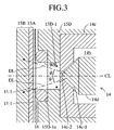
- FIG. 3 is an enlarged sectional view showing portions of the
solenoid-operated on-off discharge valve and the injection unit shown in FIG.
2, the portions being located near the distal end portion of the
solenoid-operated on-off discharge valve;
- FIG. 4 is a plan view of the injection device shown in FIG. 2;
- FIG. 5 is a sectional view of the injection device cut by a plane
extending along line V-V of FIG. 4;
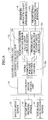
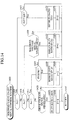
- FIG. 6 is a detailed block diagram of an electrical control unit shown
in FIG. 1;
- FIG. 7 is a timing chart showing signals generated in the electrical
control unit shown in FIG. 6;
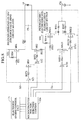
- FIG. 8 is a detailed circuit diagram of the electrical control unit
shown in FIG. 6;
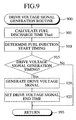
- FIG. 9 is a flowchart showing a routine which an electronic engine
control unit shown in FIG. 6 executes;
- FIG. 10 is a flowchart showing a routine which an electronic engine
control unit shown in FIG. 6 executes;
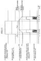
- FIG. 11 is a timing chart showing (A) a drive voltage signal, (B) a
solenoid valve on-off signal, (C) liquid pressure in a liquid feed path, (D) a
piezoelectric-element activation instruction signal, and (E) a
piezoelectric-element drive signal to be applied to
piezoelectric/electrostrictive elements;
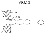
- FIG. 12 is a view showing the condition of liquid injected from the
liquid injection apparatus shown in FIG. 1;
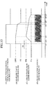
- FIG. 13 is a timing chart showing the action of a liquid injection
apparatus according to a second embodiment of the present invention by
use of signals similar to those of FIG. 11;
- FIG. 14 is a flowchart showing a routine which a fuel injection control
microcomputer of the liquid injection apparatus according to the second
embodiment executes;
- FIG. 15 is a flowchart showing a routine which the fuel injection
control microcomputer of the liquid injection apparatus according to the
second embodiment executes;
- FIG. 16 is a timing chart showing the action of a liquid injection
apparatus according to a third embodiment of the present invention by use
of signals similar to those of FIG. 11;
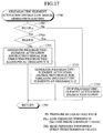
- FIG. 17 is a flowchart showing a routine which the fuel injection
control microcomputer of the liquid injection apparatus according to the third
embodiment executes;
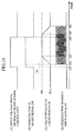
- FIG. 18 is a timing chart showing the action of a liquid injection
apparatus according to a fourth embodiment of the present invention by use
of signals similar to those of FIG. 11;
- FIG. 19 is a timing chart showing a piezoelectric-element drive
signal, among others, in a period of time when liquid pressure in a liquid
feed path is in the process of increasing in the liquid injection apparatus
according to the fourth embodiment;
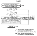
- FIG. 20 is a flowchart showing a routine which a fuel injection control
microcomputer of the liquid injection apparatus according to the fourth
embodiment executes;
- FIG. 21 is a timing chart showing the action of a liquid injection
apparatus according to a modification of the fourth embodiment by use of
signals similar to those of FIG. 11;
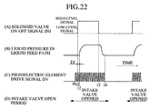
- FIG. 22 is a timing chart showing the action of a liquid injection
apparatus according to a modification of the embodiments of the present
invention;
- FIG. 23 is a plan view of a liquid injection device according to
another modification of the embodiments of the present invention; and
- FIG. 24 is a sectional view of the liquid injection device of FIG. 23
cut by a plane extending along line XXIV-XXIV of FIG. 23.
-
DESCRIPTION OF THE PREFERRED EMBODIMENTS
-
Embodiments of a liquid injection apparatus (liquid atomization
apparatus, liquid feed apparatus, or liquid droplet discharge apparatus)
according to the present invention will be described with reference to the
drawings. FIG. 1 schematically shows a first embodiment of a liquid
injection apparatus 10 according to the present invention. The liquid
injection apparatus 10 is applied to an internal combustion engine, which is
a mechanical apparatus requiring atomized liquid.
-
The liquid injection apparatus 10 is adapted to inject atomized liquid
(liquid fuel; e.g., gasoline; hereinafter may be called merely as "fuel") into a
fuel injection space 21 defined by an intake pipe (intake port) 20 of an
internal combustion engine such that the injected atomized liquid is directed
to the back surface of an intake valve 22. The liquid injection apparatus 10
includes a pressure pump (fuel pump) 11, which serves as a pressurizing
device; a liquid feed pipe (fuel pipe) 12, in which the pressure pump 11 is
installed; a pressure regulator 13, which is installed in the liquid feed pipe
12 on the discharge side of the pressure pump 11; a solenoid-operated
on-off discharge valve 14; an injection unit (atomization unit) 15, which
includes a plurality of chambers having respective
piezoelectric/electrostrictive elements formed at least on their walls and a
plurality of liquid discharge nozzles in order to atomize fuel to be injected
into the fuel injection space 21; and an electrical control unit 30 for sending
a solenoid valve on-off signal serving as a drive signal, and a
piezoelectric-element drive signal for changing the chamber volume (for
activating the piezoelectric/electrostrictive elements), to the
solenoid-operated on-off discharge valve 14 and the injection unit 15,
respectively.
-
The pressure pump 11 communicates with a bottom portion of the
liquid storage tank (fuel tank) 23 and includes an introduction portion 11 a, to
which fuel is fed from the liquid storage tank 23, and a discharge portion
11 b connected to the liquid feed pipe 12. The pressure pump 11 takes in
fuel from the liquid storage tank 23 through the introduction portion 11 a;
pressurizes the fuel to a pressure (this pressure is called "pressure pump
discharge pressure") which enables injection of the fuel into the fuel
injection space 21 via the pressure regulator 13, the solenoid-operated
on-off discharge valve 14, and the injection unit 15 (even when the
piezoelectric/electrostrictive elements of the injection unit 15 are inactive);
and discharges the pressurized fuel into the liquid feed pipe 12 from the
discharge portion 11b.
-
Pressure in the intake pipe 20 is applied to the pressure regulator 13
through unillustrated piping. On the basis of the pressure, the pressure
regulator 13 lowers (or regulates) the pressure of fuel pressurized by the
pressure pump 11 such that the pressure of fuel in the liquid feed pipe 12
between the pressure regulator 13 and the solenoid-operated on-off
discharge valve 14 becomes a pressure (called "regulation pressure") that is
higher by a predetermined pressure (a constant pressure) than the pressure
in the intake pipe 20. As a result, when the solenoid-operated on-off
discharge valve 14 is opened for a predetermined time, fuel is injected into
the intake pipe 20 in an amount substantially proportional to the
predetermined time, irrespective of pressure in the intake pipe 20.
-
The solenoid-operated on-off discharge valve 14 is a known fuel
injector (solenoid-operated on-off injection valve) which has been widely
employed in an electrically controlled fuel injection apparatus of an internal
combustion engine. FIG. 2 is a front view of the solenoid-operated on-off
discharge valve 14, showing a section of a distal end portion of the valve 14
cut by a plane including the centerline of the valve 14 and a section of the
injection unit 15―which is fixedly attached to the valve 14―cut by the same
plane. FIG. 3 is an enlarged sectional view showing portions of the
solenoid-operated on-off discharge valve 14 and the injection unit 15 shown
in FIG. 2, the portions being located near the distal end portion of the
solenoid-operated on-off discharge valve 14.
-
As shown in FIG. 2, the solenoid-operated on-off discharge valve 14
includes a liquid introduction port 14a, to which the liquid feed pipe 12 is
connected; an external tube portion 14c, which defines a fuel path 14b
communicating with the liquid introduction port 14a; a needle valve 14d,
which serves as a solenoid-operated on-off valve; and an unillustrated
solenoid mechanism for driving the needle valve 14d. As shown in FIG. 3,
a conical valve seat portion 14c-1―which assumes a shape substantially
similar to that of a distal end portion of the needle valve 14d―is provided at
a center portion of the distal end of the external tube portion 14c; and a
plurality of discharge ports (through-holes) 14c-2―which establish
communication between the interior (i.e., the fuel path 14b) of the external
tube portion 14c and the exterior of the external tube portion 14c―are
provided in the vicinity of an apex (a distal end portion) of the valve seat
portion 14c-1. The discharge ports 14c-2 are inclined by an angle with
respect to an axis CL of the needle valve 14d (solenoid-operated on-off
discharge valve 14). Notably, the view is not shown, but when the external
tube portion 14c is viewed from the direction of the axis CL, the plurality of
discharge ports 14c-2 are arranged equally spaced on the same
circumference.
-
Through employment of the above configuration, the
solenoid-operated on-off discharge valve 14 functions in the following
manner: the needle valve 14d is driven by the solenoid mechanism so as to
open the discharge ports 14c-2, whereby the fuel contained in the fuel path
14b is discharged (injected) via the discharge ports 14c-2. This state is
represented as "the solenoid-operated on-off discharge valve 14 is opened."
The state in which the needle valve 14d closes the discharge ports 14c-2 is
represented as "the solenoid-operated on-off discharge valve 14 is closed."
Since the discharge ports 14-2c are inclined with respect to the axis CL of
the needle valve 14d, fuel discharged as mentioned above is injected in
such a manner as to spread out (in a cone shape) along the side surface of
a cone whose centerline coincides with the axis CL.
-
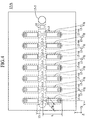
As shown in FIG. 2, the injection unit 15 includes an injection device
15A, an injection device fixation plate 15B, a retaining unit 15C for retaining
the injection device fixation plate 15B, and a sleeve 15D for fixing the distal
end of the solenoid-operated on-off discharge valve 14.
-
As shown in FIG. 4, a plan view showing the injection device 15A,
and FIG. 5, a sectional view of the injection device 15A cut by a plane
extending along line V-V of FIG. 4, the injection device 15A assumes the
shape of a substantially rectangular parallelepiped whose sides extend in
parallel with mutually orthogonal X-, Y-, and Z-axes, and includes a plurality
of ceramic thin-plate members (hereinafter called "ceramic sheets") 15a to
15f, which are sequentially arranged in layers and joined under pressure;
and a plurality of piezoelectric/electrostrictive elements 15g fixedly attached
to the outer surface (a plane extending along the X-Y plane and located
toward the positive side along the Z-axis) of the ceramic sheet 15f. The
injection device 15A includes internally a liquid feed path 15-1; a plurality of
(herein seven per row, 14 in total) mutually independent chambers 15-2; a
plurality of liquid introduction holes 15-3 for establishing communication
between the chambers 15-2 and the liquid feed path 15-1; a plurality of
liquid discharge nozzles 15-4, one end of each of the liquid discharge
nozzles 15-4 being substantially exposed to the liquid injection space 21 so
as to establish communication between the chambers 15-2 and the exterior
of the injection device 15A; and a liquid inlet 15-5.
-
The liquid feed path 15-1 is a space defined by the side wall surface
of an oblong cutout which is formed in the ceramic sheet 15c and whose
major and minor axes extend along the X- and Y-axis, respectively; the
upper surface of the ceramic sheet 15b; and the lower surface of the
ceramic sheet 15d.
-
Each of the chambers 15-2 is an elongated space (a longitudinally
extending liquid flow path portion) defined by the side wall surface of an
oblong cutout formed in the ceramic sheet 15e and having major and minor
axes extending along the direction of the Y-axis and the direction of the
X-axis, respectively, the upper surface of the ceramic sheet 15d, and the
lower surface of the ceramic sheet 15f. One end portion with respect to the
direction of the Y axis of each of the chambers 15-2 extends to a position
located above the liquid feed path 15-1, whereby each of the chambers 15-2
communicates, at the position corresponding to the one end portion, with
the liquid feed path 15-1 via the cylindrical liquid introduction hole 15-3
having diameter d and formed in the ceramic sheet 15d. Hereinafter, the
diameter d may be called merely as "introduction hole diameter d." The
other end portion with respect to the direction of the Y axis of each of the
chambers 15-2 is connected to the other end of the corresponding liquid
discharge nozzle 15-4. The above configuration allows liquid to flow in the
chambers 15-2 (flow path portions) from the liquid introduction holes 15-3 to
the side toward the liquid discharge nozzles 15-4.
-
Each of the liquid discharge nozzles 15-4 includes a cylindrical
through-hole which is formed in the ceramic sheet 15a and has diameter D
and whose one end (a liquid injection port or an opening exposed to the
liquid injection space) 15-4a is substantially exposed to the liquid injection
space 21; and cylindrical communication holes 15-4b to 15-4d, which are
formed in the ceramic sheets 15b to 15d, respectively, such that their size
(diameter) increases stepwise toward the corresponding chamber 15-2 from
the liquid injection port 15-4a. The axes of the liquid discharge nozzles
15-4 are in parallel with the Z-axis. Hereinafter, the diameter D may be
called merely as "nozzle diameter D."
-
The liquid inlet 15-5 is a space defined by the side wall of a
cylindrical through-hole which is formed in the ceramic sheets 15d to 15f at
an end portion of the injection device 15A in the positive direction of the
X-axis and at a substantially central portion of the injection device 15A in the
direction of the Y-axis. The liquid inlet 15-5 is adapted to establish
communication between the liquid feed path 15-1 and the exterior of the
injection device 15A. The liquid inlet 15-5 is connected to an upper portion
of the liquid feed path 15-1 on an imaginary plane located in the boundary
plane between the ceramic sheets 15d and 15c. A portion which partially
constitutes the liquid feed path 15-1 and faces the imaginary plane; i.e., a
portion of the upper surface of the ceramic sheet 15b is a plane portion in
parallel with the imaginary plane.
-
The shape and size of the chambers 15-2 will be additionally
described. Each of the chambers 15-2 assumes a substantially rectangular
cross section as cut at its longitudinally (along the direction of the Y-axis)
central portion (flow path portion) by a plane (X-Z plane) perpendicular to
the direction of liquid flow. Major axis L (length along the Y-axis) and
minor axis W (length along the X-axis, or length of a first side of the
rectangle) of the elongated flow path portion are 3.5 mm and 0.35 mm,
respectively. Height T (length along the Z-axis, or length of a second side
perpendicular to the first side of the rectangle) of the flow path portion is
0.15 mm. In other words, in the rectangular cross-sectional shape of the
flow path portion, the ratio (T/W) of the length (height T) of the second side
perpendicular to the first side (minor axis W) on which the
piezoelectric/electrostrictive element is provided, to the length of the first
side (minor axis W) is 0.15/0.35=0.43. Preferably, the ratio (T/W) is
greater than zero (0) and smaller than one (1). Through selection of such
a ratio (T/W), vibration energy of the piezoelectric/electrostrictive elements
15g can be efficiently transmitted to fuel contained in the corresponding
chambers 15-2.
-
The diameter D of the liquid discharge nozzle end portion 15-4a and
the diameter d of the liquid introduction hole 15-3 are 0.031 mm and 0.025
mm, respectively. In this case, preferably, cross-sectional area S1 (=W×T)
of the flow path of the chamber 15-2 is greater than cross-sectional area S2
(=π·(D/2)2) of the liquid discharge nozzle end portion 15-4a and greater than
cross-sectional area S3 (=π·(d/2)2) of the liquid introduction hole 15-3. Also,
preferably, for atomization of liquid, the cross-sectional area S2 is greater
than the cross-sectional area S3.
-
The piezoelectric/electrostrictive elements 15g are slightly smaller
than the corresponding chambers 15-2 as viewed in plane (as viewed from
the positive direction of the Z-axis); are fixed to the upper surface (a wall
surface including a side of the rectangular cross-sectional shape of the flow
path portion of each chamber 15-2) of the ceramic sheet 15f in such a
manner as to be disposed within the corresponding chambers 15-2 as
viewed in plane; and are activated (driven) in response to a
piezoelectric-element drive signal DV (also called a
"piezoelectric/electrostrictive-element drive signal DV") which a
piezoelectric-element drive signal generation device (circuit) of the electrical
control unit 30 applies between unillustrated electrodes provided on the
upper and lower surfaces of each of the piezoelectric/electrostrictive
elements 15g, thereby causing deformation of the ceramic sheet 15f (upper
walls of the chambers 15-2), and an associated volume change ΔV of the
corresponding chambers 15-2.
-
The following method is employed for making the
ceramic sheets
15a to 15f and a laminate of the
ceramic sheets 15a to 15f.
- 1: Ceramic green sheets are formed by use of zirconia powder having a
particle size of 0.1 to several micrometers.
- 2: Punching is performed on this ceramic green sheet by use of punches
and dies so as to form cutouts corresponding to those in the ceramic sheets
15a to 15e shown in FIG. 5 (cutouts corresponding to the chambers 15-2,
the liquid introduction holes 15-3, the liquid feed path 15-1, the liquid
discharge nozzles 15-4, and the liquid inlet 15-5 (see FIG. 4)).
- 3: The ceramic green sheets are arranged in layers. The resultant
laminate is heated under pressure, followed by subjection to firing for 2
hours at 1,550°C for integration.
-
-
The piezoelectric/electrostrictive elements 15g each being
sandwiched between electrodes are formed on the completed laminate of
ceramic sheets at positions corresponding to the chambers. Thus is
fabricated the injection device 15A. Through such fabrication of the
injection device 15A in a monolithic form by use of zirconia ceramic,
characteristics of zirconia ceramic allow the injection device 15A to maintain
high durability against frequent deformation of the wall surface 15f effected
by the piezoelectric/electrostrictive elements 15g; and a liquid injection
device having a plurality of liquid discharge nozzles 15-4 can be
implemented in such a small size of up to several centimeters in overall
length and can be readily fabricated at low cost.
-
As shown in FIGS. 2 and 3, the thus-configured injection device 15A
is fixedly attached to the injection device fixation plate 15B. The injection
device fixation plate 15B assumes a rectangular shape slightly greater than
the injection device 15A as viewed in plane. The injection device fixation
plate 15B has unillustrated through-holes formed therein such that, when
the injection device 15A is fixedly attached thereto, the through-holes face
the corresponding liquid injection ports 15-4a of the injection device 15A,
thereby exposing the liquid injection ports 15-4a to the exterior of the
injection device 15A via the through-holes. The injection device fixation
plate 15B is fixedly retained at its peripheral portion by means of the
retaining unit 15C.
-
The retaining unit 15C assumes an external shape identical with that
of the injection device fixation plate 15B as viewed in plane. As shown in
FIG. 1, the retaining unit 15C is fixedly attached to the intake pipe 20 of the
internal combustion engine at its peripheral portion by use of unillustrated
bolts. As shown in FIG. 2, a through-hole whose diameter is slightly
greater than that of the external tube portion 14c of the solenoid-operated
on-off discharge valve 14 is formed in the retaining unit 15C at a central
portion thereof. The external tube portion 14c is inserted into the
through-hole.
-
As shown in FIGS. 2 and 3, the sleeve (a closed space formation
member) 15D assumes such a cylindrical shape that its inside diameter is
equal to the outside diameter of the external tube portion 14c of the
solenoid-operated on-off discharge valve 14 and that its outside diameter is
equal to the inside diameter of the aforementioned through-hole of the
retaining unit 15C. One end of the sleeve 15D is closed, and the other end
is opened. As shown in FIG. 3, an opening 15D-1 having a diameter
substantially equal to that of the liquid inlet 15-5 of the injection device 15A
is formed in the closed end portion of the sleeve 15D at the center thereof.
An O-ring groove 15D-1 a is formed on an inner circumferential wall surface
forming the opening 15D-1 and on the outer surface of the closed end
portion of the sleeve 15D.
-
The external tube portion 14c of the solenoid-operated on-off
discharge valve 14 is press-fitted into the sleeve 15D from the open end of
the sleeve 15D until the external tube portion 14c abuts the inside wall
surface of the closed end of the sleeve 15D. The sleeve 15D is press-fitted
into the aforementioned through-hole of the retaining unit 15C. At this time,
an O-ring 16 fitted into the O-ring groove 15D-1 a abuts the ceramic sheet
15f of the injection device 15A.
-
In this manner, the solenoid-operated on-off discharge valve 14 and
the injection unit 15 are assembled together, whereby a closed cylindrical
space is formed between the discharge ports 14c-2 of the solenoid-operated
on-off discharge valve 14 (a portion that can also be said to be the closed
end face (the outside face of the closed end)―where the discharge ports
14c-2 are formed―of the external tube portion 14c of the solenoid-operated
on-off discharge valve 14, or a portion that can also be said to be the
outside surface of a wall portion of the cylindrical external tube portion 14c
where the discharge ports 14c-2 is formed) and the liquid inlet 15-5 of the
injection device 15A. In this state, the axis of the opening (closed
cylindrical space) 15D-1 of the sleeve 15D coincides with the axis of the
liquid inlet 15-5 of the injection device 15A and with the axis CL of the
needle valve 14d. As described above, the sleeve 15D is disposed
between the discharge ports 14c-2 of the solenoid-operated on-off discharge
valve 14 and the liquid inlet (liquid inlet portion) 15-5 of the injection device
15A, and forms a closed cylindrical space―whose diameter is substantially
equal to that of the liquid inlet 15-5 and whose axis coincides with the axis
CL of the liquid inlet 15-5 and with the axis CL of the needle valve
14d―between the discharge ports 14c-2 and the liquid inlet 15-5.
-
As mentioned previously, the discharge ports 14c-2 are inclined by
angle with respect to the axis CL of the needle valve 14d (the axis of the
closed cylindrical space). Accordingly, fuel discharged from the
solenoid-operated on-off discharge valve 14 spreads out toward the
injection device 15A at the angle with respect to the axis CL, in the
opening 15D-1 (i.e., the aforementioned closed cylindrical space) of the
sleeve 15D. In other words, the distance of fuel discharged from the
discharge ports 14c-2 as measured from the axis CL of the closed
cylindrical space increases with the distance from the discharge ports 14c-2
toward the liquid inlet 15-5.
-
In the present embodiment, the angle is determined such that the
thus-discharged fuel reaches the aforementioned plane portion of the liquid
feed path 15-1 (the upper surface of the ceramic sheet 15b) without
reaching the inner circumferential wall surface (excluding the inner
circumferential wall surface of the O-ring groove 15D-1 a) which forms the
opening 15D-1 (i.e., the aforementioned closed cylindrical space) of the
sleeve 15D, and without reaching a wall surface WP (represented in FIG. 3
by the double-dot-and-dash line) which is formed through imaginary
extension of the inner circumferential wall surface to the plane portion of the
liquid feed path 15-1.
-
In other words, the solenoid-operated on-off discharge valve 14 is
arranged and configured such that the discharge flow line (represented in
FIG. 3 by the dot-and-dash line DL) of liquid discharged from the discharge
ports 14c-2 directly intersects the plane portion of the liquid feed path 15-1
without intersecting the cylindrical side wall 15D-1 which forms the closed
space of the sleeve 15D, and without intersecting the side wall WP which is
formed through imaginary extension of the side wall 15D-1 to the plane
portion of the liquid feed path 15-1.
-
Through employment of the above configuration, fuel which is
discharged from the discharge ports 14c-2 of the solenoid-operated on-off
discharge valve 14 and fed into the liquid feed path 15-1 via the liquid inlet
15-5 is introduced into the chambers 15-2 via the corresponding liquid
introduction holes 15-3. Vibration energy is applied to the fuel contained in
the chambers 15-2, whereby the fuel is injected in the form of fine
(atomized) liquid droplets into the intake pipe 20 via the liquid injection ports
15-4a of the liquid discharge nozzles 15-4 and the through-holes formed in
the injection device fixation plate 15B.
-
As shown in FIG. 6, the electrical control unit 30 includes an
electronic engine control unit 31 and an electronic fuel injection control
circuit 32, which is connected to the electronic engine control unit 31.
-
The electronic engine control unit 31 is connected to sensors, such
as a known engine speed sensor 33, a known intake pipe pressure sensor
34, and a liquid feed path pressure sensor 35. Receiving engine speed N
and intake pipe pressure P from these sensors, the electronic engine control
unit 31 determines the amount of fuel and injection start timing required for
an internal combustion engine, and sends signals related to the determined
amount of fuel and injection start timing, such as a drive voltage signal, to
the electronic fuel injection control circuit 32.
-
The liquid feed path pressure sensor (pressure detection device) 35
is adapted to detect the pressure of liquid contained in the liquid feed path
15-1. As shown in FIGS. 4 and 5, the liquid feed path pressure sensor 35
is fixed on the upper surface of the ceramic sheet 15f at a position located
above the liquid feed path 15-1 with respect to the direction of the Z-axis.
The liquid feed path 15-1 has a communication path which extends in the
direction of the Z-axis to the lower surface of the ceramic sheet 15f at a
position corresponding to that of the liquid feed path pressure sensor 35.
Therefore, the ceramic sheet 15f is deformed according to the pressure of
liquid contained in the liquid feed path 15-1. The liquid feed path pressure
sensor 35 is formed of a piezoelectric element or a piezoresistance element
and generates a voltage signal according to the deformation of the ceramic
sheet 15f.
-
Hereinafter, the pressure of liquid contained in the liquid feed path
15-1 and detected by the liquid feed path pressure sensor 35 may be called
"detected-liquid-pressure-in-path PS." The liquid feed path pressure
sensor 35 may be a pressure detection device for detecting liquid pressure
at a certain location in a liquid path extending from the discharge ports
14c-2 of the solenoid-operated on-off discharge valve 14 to the liquid
injection port 15-4a of each of the liquid discharge nozzles 15-4 (one end of
each liquid discharge nozzle 15-4 exposed to the liquid injection space 21).
In other words, the pressure detection device may be a pressure sensor (a
piezoelectric element, a piezoresistance element, or the like) disposed in
the liquid inlet 15-5, the chamber 15-2, or the liquid discharge nozzle 15-4.
Notably, the expression "to be disposed in the liquid inlet 15-5, the chamber
15-2, or the liquid discharge nozzle 15-4" means being disposed at a
position where the pressure of liquid contained in the liquid inlet 15-5, the
chamber 15-2, or the liquid discharge nozzle 15-4 is detected.
-
Furthermore, the liquid feed path pressure sensor 35 may include a
low-pass filter for the following purpose: a detection signal is filtered by the
low-pass filter so as to obtain a time average of the pressure of liquid
contained in the liquid feed path 15-1, and the thus-obtained signal is output
to the electronic engine control unit 31 or the like as the
detected-liquid-pressure-in-path PS. Alternatively, such filtering may be
performed within the electronic engine control unit 31 by software means.
-
The electronic fuel injection control circuit 32 includes a
microcomputer 32a for fuel injection control (hereinafter referred to as the
"fuel injection control microcomputer 32a"), a solenoid-operated on-off
discharge valve drive circuit section 32b, and a
piezoelectric/electrostrictive-element drive circuit section 32c. The fuel
injection control microcomputer 32a receives the aforementioned drive
voltage signal from the electronic engine control unit 31 and sends a control
signal based on the received drive voltage signal to the solenoid-operated
on-off discharge valve drive circuit section 32b and the
piezoelectric/electrostrictive-element drive circuit section 32c. Notably, the
fuel injection control microcomputer 32a inputs the
detected-liquid-pressure-in-path PS from the liquid feed path pressure
sensor 35 as needed.
-
As shown in the timing chart of FIG. 7, the solenoid-operated on-off
discharge valve drive circuit section 32b outputs a solenoid valve on-off
signal of rectangular wave to an unillustrated solenoid mechanism of the
solenoid-operated on-off discharge valve 14. Upon generation of the
solenoid valve on-off signal (i.e., when the solenoid valve on-off signal
becomes a high-level signal (valve ON signal)), the needle valve 14d of the
solenoid-operated on-off discharge valve 14 is moved to open the discharge
ports 14c-2, and thus fuel is discharged into the liquid feed path 15-1 from
the solenoid-operated on-off discharge valve 14 via the liquid inlet 15-5 of
the injection device 15A. By contrast, when generation of the solenoid
valve on-off signal is stopped (i.e., when the solenoid valve on-off signal
becomes a low-level signal (valve OFF signal)), the needle valve 14d closes
the discharge ports 14c-2, and thus discharge of fuel into the liquid feed
path 15-1 is stopped.
-
As shown in FIG. 7, the piezoelectric/electrostrictive-element drive
circuit section 32c applies the piezoelectric-element drive signal DV of
frequency f (period T=1/f) between unillustrated electrodes of each of the
piezoelectric/electrostrictive elements 15g on the basis of a control signal
from the fuel injection control microcomputer 32a. The
piezoelectric-element drive signal DV has such a waveform as to increase
steeply from 0 (V) to a predetermined maximum electric potential Vmax (V),
subsequently maintain the maximum electric potential Vmax for only a short
period of time, and then decrease steeply toward 0 (V).
-
The drive frequency f of the piezoelectric-element drive signal DV is
set to a frequency, for example near 50 kHz, equal to the resonance
frequency (natural frequency) of the injection device 15A, which depends on
the structure of the chambers 15-2, the structure of the liquid discharge
nozzles 15-4, the nozzle diameter D, the introduction hole diameter d, the
shape of a portion of each of the piezoelectric/electrostrictive elements 15g
which causes deformation of the ceramic sheet 15f, liquid to be used, and
the like.
-
When a state in which the solenoid valve on-off signal is generated
(the solenoid valve on-off signal assumes a high level) continues, the
pressure of liquid contained in the liquid feed path 15-1 converges to a
constant, high pressure, whereby injection of liquid from the liquid discharge
nozzles 15-4 continues. When a state in which the solenoid-operated
on-off signal is not generated (the solenoid valve on-off signal assumes a
low level) continues, the pressure of liquid contained in the liquid feed path
15-1 converges to a constant, low pressure. At this time, liquid is not
injected from the liquid discharge nozzles 15-4.
-
The configuration and action of the above-described
solenoid-operated on-off discharge valve drive circuit section 32b and those
of the above-described piezoelectric/electrostrictive-element drive circuit
section 32c will next be described in detail with reference to FIG. 7 and FIG.
8, which shows electric circuit diagrams of these circuit sections.
-
As shown in FIG. 8, the solenoid-operated on-off discharge valve
drive circuit section 32b includes two Schmitt trigger circuits ST1 and ST2;
three field effect transistors (MOS FET) MS1 to MS3; a plurality of resistors
RST1, RST2, and RS1 to RS4; and one capacitor CS. Among these
resistors, the resistors RST1 and RST2 are output current limiting resistors
for the Schmitt trigger circuits ST1 and ST2, respectively.
-
As shown in FIG. 7, when the electronic engine control unit 31
outputs the drive voltage signal which changes from a low level to a high
level, to the fuel injection control microcomputer 32a, the fuel injection
control microcomputer 32a outputs a signal (not shown) which changes from
a high level to a low level, to the Schmitt trigger circuit ST1. Also, the fuel
injection control microcomputer 32a outputs a signal (not shown) which
changes from a low level to a high level, to the Schmitt trigger circuit ST2.
-
This causes the Schmitt trigger circuit ST1 to output a high-level
signal. Accordingly, the field effect transistor MS3 turns ON (electrically
conductive). As a result, the field effect transistor MS1 also turns ON.
Since the Schmitt trigger circuit ST2 outputs a low-level signal, the field
effect transistor MS2 turns OFF (electrically nonconductive).
-
This causes the power supply voltage VP1 to be applied to the
capacitor CS and the solenoid-operated on-off discharge valve 14 (the
solenoid mechanism thereof), and thus the capacitor CS is charged. At
this time, current flows to the solenoid-operated on-off discharge valve 14,
and after the elapse of time Td―which is a predetermined delay time (a
so-called ineffective injection time) stemming from an inductor
component―the needle valve 14d starts to move. As a result, discharge of
liquid into the liquid feed path 15-1 from the solenoid-operated on-off
discharge valve 14 starts, so that the liquid pressure in the liquid feed path
15-1 starts to rise from a constant, low pressure.
-
Meanwhile, when the electronic engine control unit 31 sends the
drive voltage signal which changes from a high level to a low level, to the
fuel injection control microcomputer 32a, the fuel injection control
microcomputer 32a outputs a control signal (not shown) which changes from
a low level to a high level, to the Schmitt trigger circuit ST1. Also, the fuel
injection control microcomputer 32a outputs a control signal (not shown)
which changes from a high level to a low level, to the Schmitt trigger circuit
ST2.
-
This causes the Schmitt trigger circuit ST1 to output a low-level
signal. Accordingly, the field effect transistor MS3 turns OFF, and thus the
field effect transistor MS1 turns OFF. Also, since the Schmitt trigger circuit
ST2 outputs a high-level signal, the field effect transistor MS2 turns ON.
As a result, the power supply voltage VP1 is not applied to the capacitor CS
and the solenoid-operated on-off discharge valve 14 (the solenoid
mechanism thereof); and the capacitor CS is grounded via the field effect
transistor MS2, whereby charges stored in the capacitor CS are discharged.
Thus, application of electricity to the solenoid-operated on-off discharge
valve 14 is stopped, and, after the elapse of a predetermined time after the
field effect transistor MS2 has turned ON, the needle valve 14d starts to
move toward the initial position. Accordingly, the amount of liquid
discharged into the liquid feed path 15-1 from the solenoid-operated on-off
discharge valve 14 reduces; as a result, liquid pressure in the liquid feed
path 15-1 decreases toward the aforementioned constant, low pressure from
the aforementioned constant, high pressure.
-
The above is the action of the solenoid-operated on-off discharge
valve drive circuit section 32b. Notably, the capacitor CS functions to
maintain voltage to be applied to the solenoid mechanism of the
solenoid-operated on-off discharge valve 14 when the power supply voltage
VP1 is applied to the solenoid mechanism. Next, the
piezoelectric/electrostrictive-element drive circuit section 32c will be
described.
-
As shown in FIG. 8, the piezoelectric/electrostrictive-element drive
circuit section 32c includes two Schmitt trigger circuits ST11 and ST12;
three field effect transistors (MOS FET) MS11 to MS13; a plurality of
resistors RST11, RST12, and RS11 to RS14; and two coils L1 and L2.
Among these resistors, the resistors RST11 and RST12 are output current
limiting resistors for the Schmitt trigger circuits ST11 and ST12,
respectively.
-
As shown in FIG. 7, when the electronic engine control unit 31
outputs the drive voltage signal (in this case, may be called a
"piezoelectric-element activation instruction signal") which changes from a
low level to a high level, to the fuel injection control microcomputer 32a, on
the basis of the drive voltage signal, the fuel injection control microcomputer
32a outputs, as a control signal (not shown), a pulse of a constant width (a
rectangular wave formed such that voltage drops to 0 (V) from a constant
voltage, is then maintained at 0 (V) for a predetermined period of time, and
is subsequently restored to the constant voltage) to the Schmitt trigger
circuit ST11 every elapse of period T (frequency f=1/T). The fuel injection
control microcomputer 32a outputs a similar pulse, as a control signal, to the
Schmitt trigger circuit ST12 in such a manner as to slightly lag the control
signal sent to the Schmitt trigger circuit ST11.
-
When a pulse is input to the Schmitt trigger circuit ST11, the Schmitt
trigger circuit ST11 outputs a high-level signal. Accordingly, the field effect
transistor MS13 turns ON; as a result, the field effect transistor MS11 also
turns ON. At this point of time, the Schmitt trigger circuit ST12 outputs a
low-level signal; thus, the field effect transistor MS12 remains OFF.
Therefore, since the power supply voltage VP2 is applied to the
piezoelectric/electrostrictive elements 15g via the coil L1 and the resistor
RS11, the piezoelectric/electrostrictive elements 15g cause deformation of
the ceramic sheet 15f, whereby the corresponding chambers 15-2 reduce in
volume.
-
Subsequently, the pulse input to the Schmitt trigger circuit ST11
disappears. This causes the Schmitt trigger circuit ST11 to output a
low-level signal, and thus the field effect transistors MS13 and MS11 turn
OFF. Even at this point of time, no pulse is input to the Schmitt trigger
circuit ST12. Therefore, the Schmitt trigger circuit ST12 outputs a low-level
signal, and thus the field effect transistor MS12 remains OFF. As a result,
the piezoelectric/electrostrictive elements 15g retain stored charges,
whereby the electric potential between electrodes of each of the
piezoelectric/electrostrictive elements 15g is maintained at the maximum
value Vmax.
-
Subsequently, the fuel injection control microcomputer 32a sends
the aforementioned pulse to the Schmitt trigger circuit ST12 only. This
causes the Schmitt trigger circuit ST12 to output a high-level signal, and
thus the field effect transistor MS12 turns ON. As a result, the
piezoelectric/electrostrictive elements 15g are grounded via the resistor
RS12, the coil L2, and the field effect transistor MS12, whereby charges
stored in the piezoelectric/electrostrictive elements 15g are discharged.
Thus, the piezoelectric/electrostrictive elements 15g begin to be restored to
the initial shape, whereby the corresponding chambers 15-2 increase in
volume.
-
As mentioned previously, such an action is repeated every elapse of
the period T (frequency f=1/T), whereby vibration energy is transmitted to
liquid contained in the chambers 15-2. The above is the action of the
piezoelectric/electrostrictive-element drive circuit section 32c.
-
Notably, herein the expression "to generate the solenoid valve on-off
signal" means applying the power supply voltage VP1 to the
solenoid-operated valve 14 via the field effect transistor MS1 and the like;
and the expression "to stop generation of the solenoid valve on-off signal"
means stopping application of the power supply voltage VP1 to the
solenoid-operated valve 14. The expression "to generate the
piezoelectric-element drive signal DV" means performing charge and
discharge of the piezoelectric/electrostrictive elements 15g at the
above-mentioned frequency f (period T); and the expression "to stop
generation of the piezoelectric-element drive signal DV" means stopping the
above-described charge and discharge repeatedly performed on the
piezoelectric/electrostrictive elements 15g (i.e., it means starting continuous
grounding of the piezoelectric/electrostrictive elements 15g via the field
effect transistor MS12).
-
Next, the action of the liquid injection apparatus 10 having the
above-described configuration will be described with reference to the
flowcharts of FIGS. 9 and 10 and the timing chart of FIG. 11. The
electronic engine control unit 31 repeatedly executes the drive voltage
signal generation routine of FIG. 9 every elapse of a predetermined time.
Accordingly, when predetermined timing is reached, the electronic engine
control unit 31 starts processing from Step 900 and proceeds to Step 905.
At Step 905, on the basis of engine operation conditions, such as engine
speed N and intake pipe pressure P, the electronic engine control unit 31
determines time (fuel discharge time Tfuel) during which the
solenoid-operated on-off discharge valve 14 is opened to thereby inject fuel.
-
Next, the electronic engine control unit 31 proceeds to Step 910 and
determines the timing of starting discharge of fuel (fuel injection start timing).
Fuel injection start timing is determined in terms of a crank angle before the
top dead center of intake of an engine. On the basis of engine speed N
and current time indicated by the timer of the electronic engine control unit
31, the crank angle is converted to time as indicated by the timer. Herein,
fuel injection start timing is time t3 in FIG. 11.
-
Next, at Step 915, the electronic engine control unit 31 determines
whether or not the current point of time is the timing of generating the drive
voltage signal. This drive voltage generation timing is time t1, which is a
slight time (a so-called ineffective injection time Td, which is a delay time
stemming from inductance of the solenoid mechanism of the
solenoid-operated on-off discharge valve 14) before t3―fuel injection start
timing. When the current point of time is not drive voltage generation
timing, the electronic engine control unit 31 forms a "No" judgment at Step
915 and proceeds to Step 995, thereby ending the present routine for the
time being.
-
Meanwhile, when the current point of time is drive voltage
generation timing, the electronic engine control unit 31 forms a "Yes"
judgment at Step 915 and proceeds to Step 920, where the unit 31
generates the drive voltage signal. Then, at Step 925, the electronic
engine control unit 31 sets a time (time t5 in the example of FIG. 11)
obtained through adding the ineffective injection time Td and the fuel
discharge time Tfuel to a current time, in an unillustrated register as a drive
voltage signal end time. Then, proceeding to Step 995, the electronic
engine control unit 31 ends the present routine for the time being. When a
time indicated by the timer of the electronic engine control unit 31 coincides
with the drive voltage signal end time, the electronic engine control unit 31
ends generation of the drive voltage signal. The above-described action
causes the drive voltage signal of high level to be sent to the fuel injection
control microcomputer 32a during the period of time ranging from t1 to t5.
-
Upon reception of the drive voltage signal at time t1 from the
electronic engine control unit 31, the fuel injection control microcomputer
32a sends the aforementioned control signal to the solenoid-operated on-off
discharge valve drive circuit section 32b. As a result, since the
solenoid-operated on-off discharge valve drive circuit section 32b issues the
solenoid valve on-off signal (a high-level signal) to the solenoid-operated
on-off discharge valve 14, when time t2 slightly after time t1 is reached, the
needle valve 14d starts to move, thereby starting to open the discharge
ports 14c-2.
-
This causes start of discharge/feed of fuel contained in the fuel path
14b into the liquid feed path 15-1 of the injection device 15A from the
discharge ports 14c-2 via the closed cylindrical space of the sleeve 15D and
the liquid inlet 15-5 of the injection device 15A. As a result, as shown in
FIG. 11(C), the pressure of liquid contained in the liquid feed path 15-1
starts to rise at time t2. When, after elapse of the ineffective injection time
Td, time t3 is reached, the pressure of liquid contained in the liquid feed
path 15-1 becomes equal to or higher than a low-pressure threshold
(second predetermined value) PLo. Thus, as shown in FIG. 12, fuel is
extruded (injected) from the end face of each of the liquid injection ports
15-4a toward the liquid injection space 21 in the intake pipe 20.
-
The electronic engine control unit 31 also repeatedly executes the
piezoelectric-element activation instruction signal generation routine of FIG.
10 every elapse of a predetermined time. Accordingly, when
predetermined timing is reached, the electronic engine control unit 31 starts
processing from Step 1000 and proceeds to Step 1005. At Step 1005, the
electronic engine control unit 31 judges whether or not the
detected-liquid-pressure-in-path PS detected by the liquid feed path
pressure sensor 35 is higher than the low-pressure threshold PLo. As
mentioned previously, the low-pressure threshold PLo is the minimum liquid
pressure in the liquid feed path 15-1 (accordingly, the minimum liquid
pressure in the chambers 15-2) required for injection of fuel into the fuel
injection space 21, and is very close to "0." Notably, the low-pressure
threshold PLo may be "0."
-
When time t1 is not reached, and the drive voltage signal is not
generated, the pressure of liquid contained in the liquid feed path 15-1 is a
constant, low pressure and is lower than the low-pressure threshold PLo.
Accordingly, the electronic engine control unit 31 forms a "No" judgment at
Step 1005 and proceeds to Step 1010. At Step 1010, the electronic engine
control unit 31 stops generation of the piezoelectric-element activation
instruction signal and proceeds to Step 1095, thereby ending the present
routine for the time being. Notably, at this point of time, the
piezoelectric-element activation instruction signal is not generated; therefore,
the process of Step 1010 is a verification process for preventing generation
of the piezoelectric-element activation instruction signal.
-
Subsequently, at time t1, the drive voltage signal is generated. At
and after time t3, the pressure PS in the liquid feed path 15-1 becomes
higher than the low-pressure threshold PLo. Thus, when the electronic
engine control unit 31 proceeds to Step 1005, the unit 31 forms a "Yes"
judgment and proceeds to Step 1015. At Step 1015, the electronic engine
control unit 31 judges whether the detected-liquid-pressure-in-path PS is
equal to or higher than a high-pressure threshold PHi (first predetermined
value). The high-pressure threshold PHi is a value slightly lower than or
equal to the aforementioned constant, high pressure (the pressure of liquid
contained in the liquid feed path 15-1 as measured when the state of
generation of the solenoid valve on-off signal continues).
-
This point of time (immediately after time t3) is when the pressure
PS in the liquid feed path 15-1 has just exceeded the low-pressure threshold
PLo and is still lower than the high-pressure threshold PHi. Accordingly,
the electronic engine control unit 31 forms a "No" judgment at Step 1015
and proceeds to Step 1020. At Step 1020, the electronic engine control
unit 31 generates the piezoelectric-element activation instruction signal.
Subsequently, the electronic engine control unit 31 proceeds to Step 1095
and ends the present routine for the time being.
-
This causes the fuel injection control microcomputer 32a to receive
the piezoelectric-element activation instruction signal. Accordingly, the fuel
injection control microcomputer 32a sends a control signal to the
piezoelectric/electrostrictive-element drive circuit section 32c and causes
the drive circuit section 32c to apply, from time t3, the piezoelectric-element
drive signal DV of frequency f between the electrodes of each of the
piezoelectric/electrostrictive elements 15g.
-
As a result, as shown in FIG. 12, since vibration energy induced by
the activation of the piezoelectric/electrostrictive elements 15g is applied to
fuel contained in the corresponding chambers 15-2, constricted portions are
formed on the fuel which is extruded toward the liquid injection space 21
from the end face of each of the liquid injection ports 15-4a. Thus, a
leading end portion of the fuel leaves the remaining portion of the fuel while
being torn off at its constricted portion. As a result, uniformly and finely
atomized fuel is injected into the intake pipe 20.
-
Subsequently, when, after the elapse of time, time t4 is reached, the
pressure in the liquid feed path 15-1 becomes equal to or higher than the
high-pressure threshold PHi. Thus, the electronic engine control unit 31
forms a "Yes" judgment at Steps 1005 and 1015 and proceeds to Step 1010.
At Step 1010, the electronic engine control unit 31 stops generation of the
piezoelectric-element activation instruction signal. As a result, the fuel
injection control microcomputer 32a causes the
piezoelectric/electrostrictive-element drive circuit section 32c to stop
generation of the piezoelectric-element drive signal DV.
-
Next, when time t5 is reached, as mentioned previously, the drive
voltage signal is caused to disappear, and thus the solenoid valve on-off
signal disappears. As a result, when a predetermined time elapses,
discharge of the capacitor CS progresses. Thus the solenoid-operated
on-off discharge valve 14 starts to close. Accordingly, the pressure in the
liquid feed path 15-1 starts to decrease toward "0" from a value equal to or
higher than the high-pressure threshold PHi. At time t6, the pressure
becomes equal to or lower than the high-pressure threshold PHi. At this
time, when the electronic engine control unit 31 executes the routine of FIG.
10, the unit 31 forms a "Yes" judgment at Step 1005 and forms a "No"
judgment at Step 1015. Accordingly, the electronic engine control unit 31
proceeds to Step 1020 and again generates the piezoelectric-element
activation instruction signal.
-
As a result, since the fuel injection control microcomputer 32a
causes the piezoelectric/electrostrictive-element drive circuit section 32c to
generate the piezoelectric-element drive signal DV, vibration energy induced
by the activation of the piezoelectric/electrostrictive elements 15g is again
applied to fuel contained in the corresponding chambers 15-2, whereby
atomization of fuel is performed.
-
Subsequently, when time t7 is reached, the pressure in the liquid
feed path 15-1 drops to the low-pressure threshold PLo or lower. Thus,
when the electronic engine control unit 31 executes the routine of FIG. 10,
the unit 31 forms a "No" judgment at Step 1005 and proceeds to Step 1010.
At Step 1010, the electronic engine control unit 31 stops generation of the
piezoelectric-element activation instruction signal. As a result, the fuel
injection control microcomputer 32a causes the
piezoelectric/electrostrictive-element drive circuit section 32c to stop
generation of the piezoelectric-element drive signal DV. Then, at time t8,
the pressure in the liquid feed path 15-1 becomes "0" (a constant, low
pressure).
-
The above is the action of the liquid injection apparatus 10
associated with a single fuel injection. As described above, the liquid
injection apparatus 10 (electrical control unit 30) changes the
piezoelectric-element drive signal DV on the basis of the
detected-liquid-pressure-in-path PS. Specifically, in the liquid injection
apparatus 10, when the detected-liquid-pressure-in-path PS is in the
process of increasing or decreasing (between time t3 and time t4 or
between time t6 and time t7) because of generation of the solenoid valve
on-off signal or stoppage of generation of the solenoid valve on-off signal,
the piezoelectric-element drive signal DV is generated to thereby activate
the piezoelectric/electrostrictive elements 15g; and when the
detected-liquid-pressure-in-path PS is a constant, low pressure (a pressure
lower than the low-pressure threshold PLo) (before time t3 and after time t7)
due to disappearance of the solenoid valve on-off signal, the
piezoelectric-element drive signal DV is not generated to thereby deactivate
the piezoelectric/electrostrictive elements 15g. Also, in the liquid injection
apparatus 10, during a period in which the detected-liquid-pressure-in-path
PS is a constant, high pressure, which is equal to or higher than the
high-pressure threshold PHi, the piezoelectric-element drive signal DV is not
generated to thereby deactivate the piezoelectric/electrostrictive elements
15g.
-
As described above, in the liquid injection apparatus 10, liquid
pressurized by the pressurizing device (pressure pump 11) is discharged
into the injection device 15A from the solenoid-operated on-off discharge
valve 14. The liquid is atomized through volume change of the chambers
15-2 of the injection device 15A and is then injected from the corresponding
liquid discharge nozzles 15-4. Since pressure required for injection of
liquid into the liquid injection space 21 is generated by the pressurizing
device (pressure pump 11), even when atmospheric conditions (e.g.,
pressure and temperature) within the liquid injection space 21 fluctuate
wildly due to fluctuations in, for example, operating conditions of a machine
to which the liquid injection apparatus 10 is applied, the liquid can be
injected and fed stably in the form of expected fine droplets.
-
Furthermore, at least when the pressure of liquid contained in the
liquid feed path is in the process of increasing due to generation of the
solenoid valve on-off signal (the time between t3 and t4 in which the
detected-liquid-pressure-in-path PS is in the process of increasing) or when
the pressure of liquid contained in the liquid feed path is in the process of
decreasing due to stoppage of generation of the solenoid valve on-off signal
(the time between t6 and t7 in which the detected-liquid-pressure-in-path PS
is in the process of lowering), the electrical control unit 30 activates
piezoelectric/electrostrictive elements 15g. Therefore, even in the case
where the injection velocity of liquid is not high enough to sufficiently
atomize the liquid because of the relatively low injection pressure of the
liquid at the time when the pressure of the liquid is in the process of
increasing or decreasing, the liquid can be appropriately atomized through
volume change of the chambers 15-2 effected by activation of the
corresponding piezoelectric/electrostrictive elements 15g.
-
When the pressure of liquid contained in the liquid feed path 15-1 is
a constant, low pressure because of disappearance of the solenoid valve
on-off signal; i.e., when liquid is never injected into the liquid injection space
21 from the liquid discharge nozzles 15-4 of the injection device 15A, the
injection device 15A does not need to perform the action of atomizing liquid.
Thus, the electrical control unit 30 is configured such that, when the
detected-liquid-pressure-in-path PS is equal to or lower than the
low-pressure threshold PLo, the unit 30 does not generate the
piezoelectric-element drive signal DV. This allows the liquid injection
apparatus 10 to avoid waste of electricity.
-
Furthermore, in the liquid injection apparatus 10, when the
detected-liquid-pressure-in-path PS is a high pressure equal to or higher
than the high-pressure threshold PHi, the piezoelectric-element drive signal
DV is not generated to thereby deactivate the piezoelectric/electrostrictive
elements 15g.
-
When the pressure of liquid contained in the liquid feed path 15-1
increases to a sufficiently high pressure (the aforementioned constant, high
pressure in excess of the high-pressure threshold PHi) due to generation of
the solenoid valve on-off signal, the velocity of liquid injected into the liquid
injection space 21 from the liquid discharge nozzles 15-4 of the injection
device 15A (the injection velocity, or the travel velocity of a liquid column)
becomes sufficiently high, whereby the liquid assumes the form of droplets
of a relatively small size by virtue of surface tension. Therefore, in such a
case (from time t4 to time t6), by means of avoidance of generation of the
piezoelectric-element drive signal DV, the liquid injection apparatus 10 can
reduce its electrical consumption.
-
Notably, preferably, in the above-described embodiment, when Q
(cc/min) represents the amount of liquid to be discharged per unit time
(discharge flow rate) from the solenoid-operated on-off discharge valve 14,
and V (cc) represents the volume of a liquid path formed between the
solenoid-operated on-off discharge valve 14 and the distal ends of the
discharge nozzles 15-4 of the injection device 15A, their ratio (V/Q) is 0.03
or less.
-
Herein, the volume V is the sum total of the volume of the closed
cylindrical space of the sleeve 15D, the volume of the liquid inlet 15-5, the
volume of the liquid feed path 15-1, the volume of the chambers 15-2, the
volume of the liquid introduction holes 15-3, and the volume of the liquid
discharge nozzles 15-4.
-
Also, preferably, a time when the solenoid valve on-off signal
assumes a high level is set in such a manner as to only fall within a time
when the intake valve 22 of an internal combustion engine is opened.
Through employment of this feature, when fuel injected from the liquid
injection apparatus 10 reaches the intake valve 22, the intake valve 22 is
open, whereby the fuel can be directly taken in a cylinder without adhesion
to, for example, the back surface of the intake valve 22, and the fuel injected
in an atomized condition is directly taken in the cylinder. Since the injected
fuel does not adhere to the intake valve 22 and the wall surface of the intake
pipe 20, the fuel economy of the internal combustion engine can be
enhanced, and the amount of an unburnt gas contained in exhaust can be
reduced.
-
Notably, preferably, the velocity of fuel injected in an atomized
condition from the liquid discharge nozzles 15-4 (the velocity of liquid
droplets or atomized droplets) is varied according to the amount of lift of the
intake valve 22 and/or the intake air velocity (wind velocity) within the intake
pipe. Through employment of this feature, fuel injected in an atomized
condition become more unlikely to adhere to a wall surface, whereby the
fuel can be directly taken in a cylinder. The velocity of fuel injected in an
atomized condition from the liquid discharge nozzles 15-4 can be changed
through changing the pressure of fuel (fuel pressure) to be fed to the
solenoid-operated on-off discharge valve 14. The fuel pressure can be
changed through changing the regulation pressure of the pressure regulator
13, or when the pressure regulator 13 is not provided, the fuel pressure can
be changed through changing the discharge pressure of the pressure pump
11.
-
Next, a liquid injection apparatus 10 according to a second
embodiment of the present invention will be described. The liquid injection
apparatus 10 according to the second embodiment differs from the liquid
injection apparatus 10 according to the first embodiment only in a pattern for
generating the solenoid valve on-off signal and the piezoelectric-element
drive signal DV. Thus, while the main focus is placed on the above point of
difference, the second embodiment will next be described with reference to
the timing chart of FIG. 13 and the flowcharts of FIGS. 14 and 15. Notably,
FIG. 13(B) shows the duty ratio (or average current) of the solenoid valve
on-off signal, which will be described later.
-
In the second embodiment, when the pressure of liquid contained in
the liquid feed path 15-1 is higher than the aforementioned constant, low
pressure (in this example, a pressure higher than the low-pressure threshold
PLo set to "0") as a result of opening of the solenoid-operated on-off
discharge valve 14; in other words, when liquid is possibly injected from the
liquid discharge nozzles 15-4, generation of the piezoelectric-element drive
signal DV is continued (see a portion of the timing chart ranging from time
t22 to time t27 in FIG. 13).
-
The solenoid valve on-off signal is generated such that the pressure
of liquid contained in the liquid feed path 15-1 increases steeply (see a
portion of the timing chart ranging from time t22 to time t23) immediately
after start of generation of the solenoid valve on-off signal and subsequently
decreases gradually (slowly) at a pressure change rate whose absolute
value is smaller than that of a pressure change rate at the time of the
increase of the liquid pressure (see a portion of the timing chart ranging
from time t23 to time t27).
-
More specifically, when, as shown in FIG. 13(A), the drive voltage
signal from the electronic engine control unit 31 arises at time t21, the fuel
injection control microcomputer 32a causes the solenoid-operated on-off
discharge valve drive circuit section 32b to generate the solenoid valve
on-off signal. At this time, the fuel injection control microcomputer 32a
generates respective control signals to the Schmitt trigger circuits ST1 and
ST2 such that the field effect transistor MS1 of the solenoid-operated on-off
discharge valve drive circuit section 32b maintains the ON state, while the
field effect transistor MS2 maintains the OFF state. In other words, a
pulsing voltage which changes between 0 (V) and the power supply voltage
VP1 (V) in the predetermined period Tp and whose duty ratio (=(time during
which VP1 (V) is maintained)/Tp) is 100% is applied to the
solenoid-operated on-off discharge valve 14.
-
This causes the needle valve 14d of the solenoid-operated on-off
discharge valve 14 to start to move toward its maximum movement position
at time t22, which is reached after the elapse of the ineffective injection time
Td, and thus the discharge ports 14c-2 start to be opened. Accordingly, as
shown in FIG. 13(C), the pressure of liquid contained in the liquid feed path
15-1 starts to steeply rise at a predetermined increase rate α1. At and
after time t22, since the detected-liquid-pressure-in-path PS becomes higher
than the low-pressure threshold PLo, the fuel injection control
microcomputer 32a causes the piezoelectric/electrostrictive-element drive
circuit section 32c to generate the piezoelectric-element drive signal DV.
-
Subsequently, at time t23 when the pressure of liquid contained in
the liquid feed path 15-1 becomes the aforementioned constant, high
pressure (in this example, at a time when the
detected-liquid-pressure-in-path PS becomes equal to or higher than the
high-pressure threshold PHi set equal to the aforementioned constant, high
pressure), the fuel injection control microcomputer 32a gradually reduces
the duty ratio of the solenoid valve on-off signal applied to the
solenoid-operated on-off discharge valve 14. As a result, since the needle
valve 14d of the solenoid-operated on-off discharge valve 14 starts to
gradually move toward the initial position, the substantial opening area of
the discharge ports 14c-2 gradually reduces. Accordingly, the pressure of
liquid contained in the liquid feed path 15-1 starts to decrease at a
predetermined reduction rate α2. At this time, the absolute value of the
reduction rate α2 is smaller than that of the increase rate α1.
-
Subsequently, at time t24, because of disappearance of the drive
voltage signal from the electronic engine control unit 31, the fuel injection
control microcomputer 32a steeply reduces the aforementioned duty ratio of
the solenoid valve on-off signal applied to the solenoid-operated on-off
discharge valve 14. Then, at time t25 when the duty ratio of the solenoid
valve on-off signal applied to the solenoid-operated on-off discharge valve
14 becomes 0%, the fuel injection control microcomputer 32a stops
generation of the solenoid valve on-off signal.
-
As a result, from time t24, the needle valve 14d of the
solenoid-operated on-off discharge valve 14 moves faster toward the initial
position, and thus the substantial opening area of the discharge ports 14c-2
steeply reduces. Accordingly, from time t26 subsequent to time t24, the
pressure of liquid contained in the liquid feed path 15-1 starts to steeply
lower at a predetermined reduction rate α3 whose absolute value is greater
than that of the reduction rate α2. At time t27, the pressure of liquid
contained in the liquid feed path 15-1 becomes the aforementioned constant,
low pressure. Notably, a time ranging from time t24 to time t26 is a time
caused by an operation lag of the needle valve 14d.
-
Meanwhile, from time t22, the fuel injection control microcomputer
32a continues generation of the piezoelectric-element drive signal DV. At
time t27 when the detected-liquid-pressure-in-path PS becomes equal to or
lower than the low-pressure threshold PLo, the fuel injection control
microcomputer 32a stops generation of the piezoelectric-element drive
signal DV.
-
In order to perform the above control, the electronic engine control
unit 31 executes the previously-described drive voltage signal generation
routine as represented by the flowchart of FIG. 9. The fuel injection control
microcomputer 32a executes the solenoid valve on-off signal control routine
as represented by the flowchart of FIG. 14 every elapse of a predetermined
time. This routine will be briefly described. Flag F indicates the state of
the solenoid valve on-off signal. When the duty ratio of the solenoid valve
on-off signal is set to 0% (i.e., when the solenoid valve on-off signal is not
generated), the flag F has the value "0" at Step 1475; when the duty ratio of
the solenoid-operated on-off signal is set to 100%, the flag F has the value
"1" at Step 1430; when the duty ratio of the solenoid valve on-off signal is
reduced by a positive value D1 per a predetermined time, the flag F has the
value "2" at Step 1445; and when the duty ratio of the solenoid valve on-off
signal is reduced by a value D2 greater than the value D1, the flag F has the
value "3" at Step 1460.
-
Accordingly, when the solenoid valve on-off signal is not generated,
the flag F has the value "0." Thus, the fuel injection control microcomputer
32a forms a "No" judgment at all of Steps 1405, 1410, and 1415, where the
microcomputer 32a judges whether or not the value of the flag F is "3," "2,"
and "1," respectively, and proceeds to Step 1420. At Step 1420, the fuel
injection control microcomputer 32a monitors whether or not the drive
voltage signal is generated. Thus, when the electronic engine control unit
31 generates the drive voltage signal, the fuel injection control
microcomputer 32a forms a "Yes" judgment at Step 1420 and proceeds to
Step 1425. At Step 1425, the fuel injection control microcomputer 32a sets
the duty ratio to 100%. Accordingly, the pressure of liquid contained in the
liquid feed path 15-1 steeply increases at the predetermined increase rate
α1.
-
At this time, since the value of the flag F becomes 1 (Step 1430), the
fuel injection control microcomputer 32a forms a "No" judgment at Steps
1405 and 1410 and a "Yes" judgment at Step 1415 and proceeds to Step
1435. At Step 1435, the fuel injection control microcomputer 32a monitors
whether or not the detected-liquid-pressure-in-path PS is equal to or higher
than the high-pressure threshold PHi. When the
detected-liquid-pressure-in-path PS becomes equal to or higher than the
high-pressure threshold PHi, the fuel injection control microcomputer 32a
forms a "Yes" judgment at Step 1435 and proceeds to Step 1440. At Step
1440, the fuel injection control microcomputer 32a reduces the duty ratio of
the solenoid valve on-off signal by the value D1. Accordingly, the pressure
of liquid contained in the liquid feed path 15-1 decreases at the
predetermined change rate α2.
-
At this time, since the value of the flag F becomes 2 (Step 1445), the
fuel injection control microcomputer 32a forms a "No" judgment at Step
1405 and a "Yes" judgment at Step 1410 and proceeds to Step 1450. At
Step 1450, the fuel injection control microcomputer 32a monitors whether or
not the drive voltage signal has disappeared. When the drive voltage
signal is judged to have disappeared, the fuel injection control
microcomputer 32a forms a "Yes" judgment at Step 1450 and proceeds to
Step 1455. At Step 1455, the fuel injection control microcomputer 32a
reduces the duty ratio of the solenoid valve on-off signal by the value D2
greater than the value D1. Accordingly, the pressure of liquid contained in
the liquid feed path 15-1 decreases at the predetermined change rate α3.
-
At this time, since the value of the flag F becomes 3 (Step 1460), the
fuel injection control microcomputer 32a forms a "Yes" judgment at Step
1405 and proceeds to Step 1465. At Step 1465, the fuel injection control
microcomputer 32a monitors whether or not the duty ratio of the solenoid
valve on-off signal is "0" or less. When the duty ratio of the solenoid valve
on-off signal becomes "0" or less, the fuel injection control microcomputer
32a forms a "Yes" judgment at Step 1465 and proceeds to Step 1470. At
Step 1470, the fuel injection control microcomputer 32a sets the duty ratio of
the solenoid valve on-off signal to "0." Then, at Step 1475, the fuel
injection control microcomputer 32a returns the value of the flag F to "0."
Through execution of the above routine, the duty ratio of the solenoid valve
on-off signal is controlled as mentioned previously.
-
Also, the fuel injection control microcomputer 32a executes the
piezoelectric-element activation instruction generation routine as
represented by the flowchart of FIG. 15 every elapse of a predetermined
time. This routine will be briefly described. When the
detected-liquid-pressure-in-path PS becomes higher than the low-pressure
threshold PLo, the fuel injection control microcomputer 32a forms a "Yes"
judgment at Step 1505 and proceeds to Step 1510. At Step 1510, the fuel
injection control microcomputer 32a generates the piezoelectric-element
activation instruction signal (the aforementioned control signal) to thereby
generate the piezoelectric-element drive signal DV. By contrast, when the
detected-liquid-pressure-in-path PS becomes equal to or lower than the
low-pressure threshold PLo, the fuel injection control microcomputer 32a
forms a "No" judgment at Step 1505 and proceeds to Step 1520. At Step
1520, the fuel injection control microcomputer 32a stops generation of the
piezoelectric-element activation instruction signal, whereby the
piezoelectric-element drive signal DV disappears.
-
As described above, in the liquid injection apparatus 10 according to
the second embodiment, when the detected-liquid-pressure-in-path PS is
higher than the constant, low pressure, the piezoelectric-element drive
signal DV is generated (time t22 to time t27). Furthermore, the liquid
injection apparatus 10 operates in the following manner. Immediately after
start of generation of the solenoid valve on-off signal (time t22 to time t23),
the pressure of liquid contained in the liquid feed path 15-1 is increased at
the pressure change rate α1. Subsequently, when the pressure PS of
liquid contained in the liquid feed path 15-1 reaches the constant, high
pressure PHi, the solenoid valve on-off signal is generated so as to
gradually decrease the pressure of liquid contained in the liquid feed path
15-1 at the pressure change rate α2 whose absolute value (|α2|) is smaller
than that (|α1|) of the pressure change rate α1 (time t23 to time t26).
-
According to the present embodiment, since, immediately after start
of generation of the solenoid valve on-off signal, the pressure of liquid
contained in the liquid feed path 15-1 steeply increases, the generation of
the solenoid valve on-off signal leads to immediate start of injection of liquid
droplets. Subsequently, the pressure of liquid contained in the liquid feed
path 15-1 continues to decrease in a relatively gradual manner (at reduction
rate α2). Therefore, the velocity of a preceding injected liquid droplet is
higher than that of a subsequent injected liquid droplet, thereby reducing the
possibility that liquid droplets injected from each of the liquid discharge
nozzles 15-4 collide within the liquid injection space 21 to form a liquid
droplet of a greater size.
-
In other words, the present embodiment is configured in such a
manner as to change the solenoid valve on-off signal on the basis of the
liquid pressure detected by the pressure detection device. Specifically,
according to the present embodiment, a point of time when the pressure of
liquid contained in the liquid feed path reaches near maximum pressure is
detected through detection of whether or not the
detected-liquid-pressure-in-path PS is equal to or higher than the
high-pressure threshold PHi. Upon detection of that point of time, the
solenoid valve on-off signal is changed such that, from that point of time on,
the pressure of liquid contained in the liquid feed path decreases in a
relatively gradual manner. Therefore, it is possible to prevent the liquid
contained in the liquid feed path from remaining at near maximum pressure
(a pressure near the high-pressure threshold PHi) for a long period of time,
thereby ensuring avoidance of collision of liquid droplets.
-
Next, a liquid injection apparatus 10 according to a third embodiment
of the present invention will be described. The liquid injection apparatus
10 according to the third embodiment differs from the liquid injection
apparatus 10 according to the first embodiment only in a pattern for
generating the solenoid valve on-off signal and the piezoelectric-element
drive signal DV. Thus, while the main focus is place on the above point of
difference, the third embodiment will next be described with reference to the
timing chart of FIG. 16 and the flowchart of FIG. 17.
-
In the third embodiment, when the pressure of liquid contained in the
liquid feed path 15-1 is in the process of increasing or decreasing as a result
of opening and closing, respectively, of the solenoid-operated on-off
discharge valve 14, the frequency f of the piezoelectric-element drive signal
DV is set lower than that when the liquid pressure is the aforementioned
constant, high pressure. In other words, when the pressure of liquid
contained in the liquid feed path 15-1 is lower than the aforementioned
constant, high pressure, the period of volume change of each of the
chambers 15-2 is set to a longer time.
-
More specifically, when the drive voltage signal from the electronic
engine control unit 31 arises at time t31, the fuel injection control
microcomputer 32a causes the solenoid-operated on-off discharge valve
drive circuit section 32b to generate the solenoid valve on-off signal. As a
result, at time t32, which is reached after the elapse of the ineffective
injection time Td, the pressure of liquid contained in the liquid feed path
15-1 starts to rise beyond the aforementioned constant, low pressure
(low-pressure threshold PLo), and, at time t33, reaches the aforementioned
constant, high pressure (high-pressure threshold PHi).
-
In this liquid pressure rise period (from time t32 to time t33), the fuel
injection control microcomputer 32a causes the
piezoelectric/electrostrictive-element drive circuit section 32c to generate
the piezoelectric-element drive signal DV of a first frequency f1. In other
words, the frequency f of the piezoelectric-element drive signal DV applied
to the piezoelectric/electrostrictive elements 15g is set to the first frequency
f1.
-
Subsequently, when the pressure of liquid contained in the liquid
feed path 15-1 becomes the aforementioned constant, high pressure (time
t33), the fuel injection control microcomputer 32a sets the frequency f of the
piezoelectric-element drive signal DV applied to the
piezoelectric/electrostrictive elements 15g to a second frequency f2 higher
than the first frequency f1. Notably, such a change in frequency f is
performed through changing (shortening) the period T (see FIG. 7) of pulses
to be sent to the Schmitt trigger circuits ST11 and ST12 from the fuel
injection control microcomputer 32a.
-
Subsequently, when the drive voltage signal from the electronic
engine control unit 31 disappears at time t34, the fuel injection control
microcomputer 32a stops generation of the solenoid valve on-off signal
applied to the solenoid-operated on-off discharge valve 14. As a result, at
time t35, which is reached after the elapse of a predetermined time from
time t34, the pressure of liquid contained in the liquid feed path 15-1 starts
to lower. Then, at time t36, the liquid pressure becomes the
aforementioned constant, low pressure.
-
Meanwhile, the fuel injection control microcomputer 32a monitors
whether or not the detected-liquid-pressure-in-path PS is lower than the
high-pressure threshold PHi. When the detected-liquid-pressure-in-path
PS becomes lower than the high-pressure threshold PHi (time t35), the fuel
injection control microcomputer 32a again sets the frequency f of the
piezoelectric-element drive signal DV applied to the
piezoelectric/electrostrictive elements 15g to the first frequency f1. Then,
when the detected-liquid-pressure-in-path PS becomes equal to or lower
than the low-pressure threshold PLo (time t36), the fuel injection control
microcomputer 32a causes the piezoelectric/electrostrictive element drive
circuit section 32c to stop generation of the piezoelectric-element drive
signal DV.
-
In order to perform the above-described control, the electronic
engine control unit 31 executes the previously described drive voltage signal
generation routine as represented by the flowchart of FIG. 9. Also, the fuel
injection control microcomputer 32a executes the piezoelectric-element
activation instruction signal generation routine as represented by the
flowchart of FIG. 17 every elapse of a predetermined time. This routine will
be briefly described. When the detected-liquid-pressure-in-path PS is
higher than the low-pressure threshold PLo and lower than the
high-pressure threshold PHi, the fuel injection control microcomputer 32a
forms a "Yes" judgment at Step 1705, where whether or not the
detected-liquid-pressure-in-path PS is higher than the low-pressure
threshold PLo is judged; forms a "No" judgment at subsequent Step 1710,
where whether or not the detected-liquid-pressure-in-path PS is equal to or
higher than the high-pressure threshold PHi is judged; and proceeds to Step
1715. At Step 1715, the fuel injection control microcomputer 32a
generates the piezoelectric-element activation instruction signal for setting
the frequency f of the piezoelectric-element drive signal DV to the first
frequency f1.
-
When the detected-liquid-pressure-in-path PS becomes equal to or
higher than the high-pressure threshold PHi, the fuel injection control
computer 32a forms a "Yes" judgment at Steps 1705 and 1710 and
proceeds to Step 1720. At Step 1720, the fuel injection control
microcomputer 32a generates the piezoelectric-element activation
instruction signal for setting the frequency f of the piezoelectric-element
drive signal DV to the second frequency f2.
-
By contrast, when the detected-liquid-pressure-in-path PS is equal
to or lower than the low-pressure threshold PLo, the fuel injection control
microcomputer 32a forms a "No" judgment at Step 1705 and proceeds to
Step 1725. At Step 1725, the fuel injection control microcomputer 32a
stops generation of the piezoelectric-element activation instruction signal, to
thereby stop generation of the piezoelectric-element drive signal DV.
Execution of the above routine generates the piezoelectric-element drive
signal DV having a frequency corresponding to the
detected-liquid-pressure-in-path PS.
-
As described above, the liquid injection apparatus 10 according to
the third embodiment is configured in such a manner as to change the
frequency of the piezoelectric-element drive signal DV according to the
detected-liquid-pressure-in-path PS. In other words, as the
detected-liquid-pressure-in-path PS increases, the electrical control unit 30
applies the piezoelectric-element drive signal DV having a higher frequency
to the piezoelectric/electrostrictive elements 15g, thereby increasing the
frequency of volume change of the chambers 15-2.
-
Since the pressure of liquid contained in the liquid feed path 15-1
determines the velocity (injection velocity) of liquid injected from each of the
liquid discharge nozzles 15-4, the degree of atomization of liquid varies with
the pressure of the liquid. Therefore, as in the case of the
above-described third embodiment, through changing the frequency f of the
piezoelectric-element drive signal DV according to the pressure of liquid
contained in the liquid feed path 15-1, liquid droplets of a desired size can
be obtained.
-
Also, in the above-described third embodiment, the
piezoelectric-element drive signal DV is changed such that the frequency f
of the piezoelectric-element drive signal DV increases with an increase in
the pressure of liquid contained in the liquid feed path 15-1. This
configuration is employed for the following reason. As the pressure of
liquid contained in the liquid feed path 15-1 increases, the velocity of liquid
injected from each of the liquid discharge nozzles 15-4 increases, and the
flow rate of liquid injected from each of the liquid discharge nozzles 15-4
(the length of a liquid column extruded into the liquid injection space 21 per
unit time from each of the liquid discharge nozzles 15-4) increases.
Therefore, through application, to the piezoelectric/electrostrictive elements
15g, of the piezoelectric-element drive signal DV whose frequency f
increases with the pressure of liquid contained in the liquid feed path 15-1,
the size of liquid droplets obtained through atomization can be rendered
uniform, irrespective of the liquid pressure.
-
Notably, in the above-described embodiment, the frequency f of the
piezoelectric-element drive signal DV is changed in two stages of the first
frequency f1 and the second frequency f2. However, the frequency f may
be changed continuously according to the detected-liquid-pressure-in-path
PS (such that the frequency f increases with an increase in the
detected-liquid-pressure-in-path PS).
-
Next, a liquid injection apparatus 10 according to a fourth
embodiment of the present invention will be described. The liquid injection
apparatus 10 according to the fourth embodiment differs from the liquid
injection apparatus 10 according to the first embodiment only in a pattern for
generating the solenoid valve on-off signal and the piezoelectric-element
drive signal DV. Thus, while the main focus is place on the above point of
difference, the fourth embodiment will next be described with reference to
the timing charts of FIGS. 18 and 19 and the flowchart of FIG. 20.
-
In the fourth embodiment, as in the case of the first embodiment,
during the period of time (ranging from time t13 to time t15 in FIG. 18) when
the liquid pressure PS in the liquid feed path 15-1 is stabilized at the
aforementioned constant, high pressure (a pressure equal to or higher than
the high-pressure threshold PHi), atomization of fuel effected through
activation of the piezoelectric/electrostrictive elements 15g is stopped.
Also, during the period of time when the pressure of liquid contained in the
liquid feed path 15-1 is in the process of increasing or lowering (ranging
from time t12 to time t13 and from time t15 to time t16), the quantity of
volume change of the chambers 15-2 caused by the piezoelectric-element
drive signal DV is reduced with an increase in the liquid pressure.
-
In order to perform the above control, the electronic engine control
unit 31 executes the previously-described drive voltage signal generation
routine as represented by the flowchart of FIG. 9. The fuel injection control
microcomputer 32a executes the piezoelectric-element activation instruction
signal generation routine as represented by the flowchart of FIG. 20 every
elapse of a predetermined time. This routine will be briefly described.
When the detected-liquid-pressure-in-path PS is higher than the
low-pressure threshold PLo and lower than the high-pressure threshold PHi,
the fuel injection control microcomputer 32a forms a "Yes" judgment at Step
2005, where whether or not the detected-liquid-pressure-in-path PS is
higher than the low-pressure threshold PLo is judged; forms a "No"
judgment at subsequent Step 2010, where whether or not the
detected-liquid-pressure-in-path PS is equal to or higher than the
high-pressure threshold PHi is judged; and proceeds to Step 2020. At
Step 2020, the fuel injection control microcomputer 32a generates the
piezoelectric-element activation instruction signal such that the maximum
value Vmax of the piezoelectric-element drive signal DV reduces with an
increase in the detected-liquid-pressure-in-path PS.
-
Specifically, during the period of time ranging from time t12 to time
t13, the fuel injection control microcomputer 32a sequentially shortens
voltage application time spans with the elapse of time; i.e., with an increase
in the detected-liquid-pressure-in-path PS, without changing the period T
between start of application of the power supply voltage VP2 to the
piezoelectric/electrostrictive elements 15g and start of application of the
next power supply voltage VP2 to the piezoelectric/electrostrictive elements
15g.
-
More specifically, as shown in FIG. 19, when the
detected-liquid-pressure-in-path PS is in the process of increasing, while the
period T between times at which application of power supply voltage VP2 is
started (the period of time between time t41 and time t45, and the period of
time between time t45 and time t49) is held constant, times Tp1, Tp3, and
Tp5―which are voltage application time spans and during which the output
signal of the Schmitt trigger circuit ST11 is at high level―are gradually
shortened with the elapse of time (with an increase in the
detected-liquid-pressure-in-path PS). Through employment of this feature,
as the detected-liquid-pressure-in-path PS increases, the maximum voltage
Vmax applied to the piezoelectric/electrostrictive elements 15g decreases.
Accordingly, the amount of deformation per activation of each of the
piezoelectric/electrostrictive elements 15g reduces, whereby the volume
change quantity ΔV in a single volume change of each of the chambers 15-2
gradually reduces.
-
Similarly, in the period of time ranging from time t15 to time t16
shown in FIG. 18, the detected pressure PS of liquid contained in the liquid
feed path 15-1 is higher than the low-pressure threshold PLo and lower than
the high-pressure threshold PHi. Thus, the fuel injection control
microcomputer 32a forms a "Yes" judgment at Step 2005; forms a "No"
judgment at Step 2010; and proceeds to Step 2020. At Step 2020, the fuel
injection control microcomputer 32a generates the piezoelectric-element
activation instruction signal such that the maximum value Vmax of the
piezoelectric-element drive signal DV reduces with an increase in the
detected-liquid-pressure-in-path PS.
-
In this case, the pressure of liquid contained in the liquid feed path
15-1 decreases with the elapse of time. Accordingly, the fuel injection
control microcomputer 32a gradually prolongs voltage application time
spans with the elapse of time without changing the period T of starting
application of the power supply voltage VP2 to the
piezoelectric/electrostrictive elements 15g. Specifically, a time during
which the output signal of the Schmitt trigger circuit ST11 is at high level;
i.e., a voltage application time span, is prolonged with a drop in the
detected-liquid-pressure-in-path PS. Through employment of this feature,
as the detected-liquid-pressure-in-path PS lowers, the amount of
deformation per activation of each of the piezoelectric/electrostrictive
elements 15g reduces, whereby the volume change quantity ΔV in a single
volume change of each of the chambers 15-2 gradually increases.
-
Meanwhile, when the detected-liquid-pressure-in-path PS is equal to
or lower than the low-pressure threshold PLo, or equal to or higher than the
high-pressure threshold PHi, the fuel injection control microcomputer 32a
forms a "No" judgment at Step 2005 or a "Yes" judgment at Step 2010 and
proceeds to Step 2015. At Step 2015, the fuel injection control
microcomputer 32a stops generation of the piezoelectric-element activation
instruction signal.
-
As described above, in the liquid injection apparatus 10 according to
the fourth embodiment, the quantity of volume change of each of the
chambers 15-2 effected by the piezoelectric-element drive signal DV
decreases with an increase in the detected-liquid-pressure-in-path PS (the
pressure of liquid contained in the liquid feed path 15-1).
-
As the pressure of liquid contained in the liquid feed path 15-1
increases, the velocity of liquid injected from the liquid discharge nozzles
15-4 increases. Thus, without an increase of the volume change quantity
ΔV (the maximum value of volume change quantity; i.e., the maximum
volume change quantity) of each of the chambers 15-2, injected liquid
droplets assume a relatively small size by virtue of surface tension.
Therefore, according to the above-described fourth embodiment, in which
the quantity ΔV of volume change of each of the chambers 15-2 effected by
the piezoelectric-element drive signal DV reduces with an increase in the
pressure of liquid contained in the liquid feed path 15-1, it is possible to
prevent the volume of each of the chambers 15-2 from changing to an
unnecessarily great extent (i.e., possible to prevent the
piezoelectric/electrostrictive elements 15g from deforming by an
unnecessarily large amount), thereby reducing the electrical consumption of
the liquid injection apparatus 10.
-
Notably, in the above-described fourth embodiment, while the
pressure of liquid contained in the liquid feed path 15-1 is the
aforementioned constant, high pressure (from time t13 to time t15),
generation of the piezoelectric-element drive signal DV is suspended.
However, as shown in FIG. 21, the piezoelectric-element drive signal DV
may be continuously generated. Also, the third embodiment and the fourth
embodiment may be combined; specifically, the frequency of the
piezoelectric-element drive signal DV increases with an increase in the
pressure of liquid contained in the liquid feed path 15-1, and the quantity ΔV
of volume change of each of the chambers 15-2 effected by the
piezoelectric-element drive signal DV reduces with an increase in the liquid
pressure.
-
As described above, in the liquid injection apparatus according to
the embodiments of the present invention, fuel is pressurized by the
pressure pump 11, whereby fuel under pressure is injected into the liquid
injection space 21 in the intake pipe 20; therefore, even when pressure in
the liquid injection space 21 (intake pressure) fluctuates, a required amount
of fuel can be stably injected.
-
Vibration energy is applied to fuel through variation of the volume of
the chambers 15-2 of the injection device 15A, whereby the fuel is atomized
and then injected from the liquid discharge nozzles 15-4. As a result, the
present liquid fuel injection apparatus can inject liquid droplets which are
atomized to a highly fine degree. Furthermore, since the injection device
15A includes a plurality of chambers 15-2 and a plurality of discharge
nozzles 15-4, even when bubbles are generated within fuel, the bubbles
tend to be finely divided, thereby avoiding great fluctuations in the amount of
injection which would otherwise result from the presence of bubbles.
-
The direction of fuel discharge from the discharge ports 14c-2 of the
solenoid-operated on-off discharge valve 14 is determined such that, as the
distance from the discharge ports 14c-2 toward the liquid feed path 15-1
increases, the distance of fuel discharged from the discharge ports 14c-2 as
measured from the axis CL of the closed cylindrical space increases.
Accordingly, discharged fuel produces a flow in a large region of the closed
cylindrical space formed in the sleeve 15D. As a result, bubbles become
unlikely to be generated, particularly, in a corner portion (marked with solid
black triangles in FIG. 3) of the closed cylindrical space in the vicinity of the
discharge ports 14c-2 of the solenoid-operated on-off discharge valve 14, or
the performance of eliminating bubbles generated in the corner portion is
enhanced. Therefore, in the above-described liquid injection apparatus, a
rise in fuel pressure is unlikely to be hindered by bubbles. Thus, since fuel
pressure can be increased as expected, fuel droplets can be injected in an
amount and at timing as required by mechanical apparatus such as an
internal combustion engine.
-
Also, the above-described liquid injection apparatus are configured
such that, before liquid discharged from the solenoid-operated on-off
discharge valve 14 is injected into the liquid injection space 21 from the
liquid discharge nozzles 15-4, the flow of the liquid makes a substantially
right-angled turn at least once (in the present example, four times).
-
Specifically, in the present liquid injection apparatus, since the liquid
inlet 15-5 and the liquid feed path 15-1 meet at right angles, the flow of
liquid discharged from the solenoid-operated on-off discharge valve 14
makes a right-angled turn at a connection portion of the liquid inlet 15-5 and
the liquid feed path 15-1. Next, since the major-axis direction of the liquid
feed path 15-1 is in parallel with the X-axis, and the axis of each of the liquid
introduction holes 15-3 is in parallel with the Z-axis, the flow of liquid makes
a right-angled turn at a connection portion of the liquid feed path 15-1 and
each of the liquid introduction holes 15-3.
-
Furthermore, since the major axis of each of the chambers 15-2 is in
parallel with the Y-axis, and the axis of each of the liquid introduction holes
15-3 is in parallel with the Z-axis, the flow of liquid makes a right-angled turn
at a connection portion of each of the chambers 15-2 and the corresponding
liquid introduction hole 15-3. Also, since the major axis of each of the
chambers 15-2 is in parallel with the Y-axis, and the axis of each of the
liquid discharge nozzles 15-4 is in parallel with the Z-axis, the flow of liquid
also makes a right-angled turn at a connection portion of each of the
chambers 15-2 and the corresponding liquid discharge nozzle 15-4.
-
According to the above-described configuration, since the flow of
liquid discharged from the solenoid-operated on-off discharge valve 14
makes a right-angled turn at least once, pulsation of liquid pressure due to
opening of the solenoid-operated on-off discharge valve 14 is reduced,
thereby enabling stable injection of liquid droplets. In other words, a
dynamic pressure which accompanies opening of the solenoid-operated
on-off discharge valve 14 becomes a static pressure, and fuel is injected
under the static pressure. As a result, fuel can be stably injected from the
liquid discharge nozzles 15-4.
-
Particularly, in the above-described liquid injection apparatus, the
injection device 15A includes a plurality of chambers 15-2 connected to the
common liquid feed path 15-1, and the flow of liquid discharged from the
solenoid-operated on-off discharge valve 14 makes a substantially
right-angled turn at a connection portion of the liquid inlet 15-5 and the liquid
feed path 15-1, whereby the pressure of liquid contained in the liquid feed
path 15-1 is stabilized. Accordingly, the pressure of liquid contained in the
chambers 15-2 becomes a static pressure to thereby be stabilized, thereby
enabling discharge of uniform liquid droplets from the liquid discharge
nozzles 15-4 connected to the corresponding chambers 15-2.
-
The solenoid-operated on-off discharge valve 14 is arranged and
configured such that the discharge flow line (represented in FIG. 3 by the
dot-and-dash line DL) of liquid discharged from the discharge ports 14c-2
directly intersects a plane portion of the liquid feed path 15-1 (the upper
surface of the ceramic sheet 15b) without intersecting the side wall 15D-1
which forms the closed cylindrical space of the sleeve 15D, and without
intersecting the side wall WP which is formed through imaginary extension
of the side wall 15D-1 to the plane portion of the liquid feed path 15-1.
-
As a result, since liquid discharged from the solenoid-operated
on-off discharge valve 14 reaches the plane portion of the liquid feed path
15-1 while maintaining high kinetic energy (velocity), the liquid is strongly
reflected from the plane portion toward the discharge ports 14c-2 in the
closed cylindrical space. Accordingly, since the flow of reflected liquid
eliminates bubbles stagnant in a corner portion (marked with solid black
triangles in FIG. 3) of the closed cylindrical space in the vicinity of the
discharge ports 14c-2, the amount of bubbles present in liquid reduces.
Accordingly, in the above-described liquid injection apparatus, a rise in
liquid pressure is more unlikely to be hindered by bubbles. Thus, since
liquid pressure can be increased as expected, liquid droplets can be injected
in an amount and at timing as required by an internal combustion engine.
-
Furthermore, since the axis of each of the liquid discharge nozzles
15-4 of the above-described embodiments is in parallel with the Z-axis,
liquid droplets discharged into the liquid injection space 21 from the liquid
discharge nozzles 15-4 do not substantially intersect in the process of flying,
thereby avoiding formation of liquid droplets of a greater size, which would
otherwise result from collision of fuel liquid droplets in the liquid injection
space 21. Thus, fuel can be sprayed in a uniformly atomized condition.
-
In the liquid injection apparatus according to the above-described
embodiments, the electrical control unit 30 is configured in such a manner
as to generate the piezoelectric-element drive signal DV so as to activate
the piezoelectric/electrostrictive elements 15g when the pressure of liquid
contained in the liquid feed path 15-1 is at least in the process of increasing
or decreasing (when the detected-liquid-pressure-in-path PS is in the
process of increasing or decreasing) because of generation of the solenoid
valve on-off signal or stoppage of generation of the solenoid valve on-off
signal, and in such a manner as not to generate the piezoelectric-element
drive signal DV when the pressure of liquid contained in the liquid feed path
15-1 is a constant, low pressure because of disappearance of the solenoid
valve on-off signal.
-
Accordingly, even in the case where the injection velocity of liquid is
not sufficiently high to sufficiently atomize the liquid, because of the
pressure of liquid contained in the liquid feed path 15-1 (and the chambers
15-2) being relatively low at the time of the pressure of the liquid being in
the process of increasing or decreasing, the liquid can be appropriately
atomized by changing the volume of the chambers 15-2 through activation
of the piezoelectric/electrostrictive elements 15g.
-
Also, when the pressure of liquid contained in the liquid feed path
15-1 (detected-liquid-pressure-in-path PS) is a constant, low pressure (a
pressure that the liquid contained in the liquid feed path 15-1 reaches as a
result of continuation of a state in which the liquid feed path 15-1 is not fed
with liquid pressurized by the pressurizing device) equal to or lower than the
predetermined value PLo because of disappearance of the solenoid valve
on-off signal; i.e., when liquid is never injected into the liquid injection space
21 from the liquid discharge nozzles 15-4 of the injection device 15A, the
injection device 15A does not need to perform the action of atomizing liquid.
Thus, in such a case, the electrical control unit 30 does not generate the
piezoelectric-element drive signal DV. This allows the liquid injection
apparatus to avoid waste of electricity.
-
Notably, the present invention is not limited to the above-described
embodiments, but may be modified in various forms without departing from
the scope of the invention. For example, as shown in FIG. 22, the
piezoelectric-element drive signal DV may be generated at time t0 which
precedes time t1 when the solenoid valve on-off signal is generated.
-
In this case, at time t0 slightly before time t2 when fuel injection
starts, the electronic engine control unit 31 sends an activation start
instruction signal for instructing start of activation of the
piezoelectric/electrostrictive elements 15g, to the fuel injection control
microcomputer 32a. In response to the activation start instruction signal,
the fuel injection control microcomputer 32a sends a control signal to the
piezoelectric/electrostrictive-element drive circuit section 32c to thereby
generate the piezoelectric-element drive signal DV. Also, the fuel injection
control microcomputer 32a monitors whether or not the
detected-liquid-pressure-in-path PS is equal to or lower than the
low-pressure threshold PLo. When the detected-liquid-pressure-in-path PS
becomes equal to or lower than the low-pressure threshold PLo, the fuel
injection control microcomputer 32a stops generation of the
piezoelectric-element drive signal DV.
-
According to the above-described configuration, at time t2 when
injection of liquid droplets possibly starts in response to generation of the
solenoid valve on-off signal, the piezoelectric/electrostrictive elements 15g
have already been driven by the piezoelectric-element drive signal DV, and
thus vibration energy has already been applied to liquid. Therefore, from
the beginning of liquid injection, liquid droplets can be injected in a reliably
atomized condition.
-
Furthermore, the above-described embodiments employ the liquid
feed path pressure sensor 35. However, one of the plurality of
piezoelectric/electrostrictive elements 15g of the injection device 15A may
be used as the liquid feed path pressure sensor 35. This allows elimination
of the liquid feed path pressure sensor 35, thereby lowering the cost of the
liquid injection apparatus.
-
The injection device 15A may be replaced with an injection device
15E shown in FIGS. 23 and 24. As shown in FIG. 23, which is a plan view
of the injection device 15E, and FIG. 24, which is a sectional view of the
injection device 15E cut by a plane extending along line XXIV-XXIV of FIG.
23, a piezoelectric/electrostrictive element 15h of the injection device 15E
assumes the form of laminate. Specifically, the
piezoelectric/electrostrictive element 15h is a "laminated piezoactuator"
formed such that laminar piezoelectric/electrostrictive elements and laminar
electrodes are alternatingly arranged in layers. When positive and
negative voltages of a drive voltage signal are applied alternatingly with the
elapse of time between paired comb-type electrodes, the
piezoelectric/electrostrictive element 15h causes the ceramic sheet 15f to be
deformed.
-
The liquid injection apparatus of the above-described embodiments
are applied to a gasoline-fueled internal combustion engine in which fuel is
injected into the intake pipe (intake port). However, the liquid injection
apparatus of the present invention can be applied to a so-called
"direct-injection-type gasoline-fueled internal combustion engine," in which
fuel is injected directly into cylinders. Specifically, when fuel is injected
directly into a cylinder by an electrically controlled fuel injection apparatus
which uses a conventional fuel injector, fuel may be caught in a gap
(crevice) between a cylinder and a piston, potentially resulting in an
increase in the amount of unburnt HC (hydrocarbon). By contrast, when
fuel is injected directly into a cylinder by use of the liquid injection apparatus
according to the present invention, fuel is injected in an atomized condition
into the cylinder, whereby the amount of fuel adhesion to the inner wall
surface of the cylinder can be reduced, or the amount of fuel entering the
gap between a cylinder and a piston can be reduced, thereby reducing
exhaust of unburnt HC.
-
Furthermore, the liquid injection apparatus according to the present
invention is effectively used as a direct injector for use in a diesel engine.
Specifically, a conventional injector involves a problem of failure to inject
atomized fuel, particularly in low-load operation of the engine, in which fuel
pressure is low. In this case, if a common-rail-type injection apparatus is
used, fuel pressure can be increased to a certain extent even when the
engine is rotating at low speed, and thus atomization of injected fuel can be
improved. However, since fuel pressure is lower as compared with the
case where the engine is rotating at high speed, fuel cannot be sufficiently
atomized. By contrast, since the liquid injection apparatus according to the
present invention is configured such that fuel is atomized through activation
of the piezoelectric/electrostrictive elements 15g, sufficiently atomized fuel
can be injected irrespective of engine load (i.e., even when the engine is
running at low load).