EP1419740B1 - Biospy forceps instrument having aspiration capability - Google Patents
Biospy forceps instrument having aspiration capability Download PDFInfo
- Publication number
- EP1419740B1 EP1419740B1 EP04001784A EP04001784A EP1419740B1 EP 1419740 B1 EP1419740 B1 EP 1419740B1 EP 04001784 A EP04001784 A EP 04001784A EP 04001784 A EP04001784 A EP 04001784A EP 1419740 B1 EP1419740 B1 EP 1419740B1
- Authority
- EP
- European Patent Office
- Prior art keywords
- sample
- tubular member
- biopsy forceps
- aspiration
- chambers
- Prior art date
- Legal status (The legal status is an assumption and is not a legal conclusion. Google has not performed a legal analysis and makes no representation as to the accuracy of the status listed.)
- Expired - Lifetime
Links
Images


Classifications
-
- A—HUMAN NECESSITIES
- A61—MEDICAL OR VETERINARY SCIENCE; HYGIENE
- A61B—DIAGNOSIS; SURGERY; IDENTIFICATION
- A61B10/00—Other methods or instruments for diagnosis, e.g. instruments for taking a cell sample, for biopsy, for vaccination diagnosis; Sex determination; Ovulation-period determination; Throat striking implements
- A61B10/02—Instruments for taking cell samples or for biopsy
- A61B10/0233—Pointed or sharp biopsy instruments
- A61B10/0266—Pointed or sharp biopsy instruments means for severing sample
-
- A—HUMAN NECESSITIES
- A61—MEDICAL OR VETERINARY SCIENCE; HYGIENE
- A61B—DIAGNOSIS; SURGERY; IDENTIFICATION
- A61B10/00—Other methods or instruments for diagnosis, e.g. instruments for taking a cell sample, for biopsy, for vaccination diagnosis; Sex determination; Ovulation-period determination; Throat striking implements
- A61B10/02—Instruments for taking cell samples or for biopsy
- A61B10/06—Biopsy forceps, e.g. with cup-shaped jaws
-
- A—HUMAN NECESSITIES
- A61—MEDICAL OR VETERINARY SCIENCE; HYGIENE
- A61B—DIAGNOSIS; SURGERY; IDENTIFICATION
- A61B10/00—Other methods or instruments for diagnosis, e.g. instruments for taking a cell sample, for biopsy, for vaccination diagnosis; Sex determination; Ovulation-period determination; Throat striking implements
- A61B10/02—Instruments for taking cell samples or for biopsy
- A61B10/0233—Pointed or sharp biopsy instruments
- A61B10/0283—Pointed or sharp biopsy instruments with vacuum aspiration, e.g. caused by retractable plunger or by connected syringe
-
- A—HUMAN NECESSITIES
- A61—MEDICAL OR VETERINARY SCIENCE; HYGIENE
- A61B—DIAGNOSIS; SURGERY; IDENTIFICATION
- A61B10/00—Other methods or instruments for diagnosis, e.g. instruments for taking a cell sample, for biopsy, for vaccination diagnosis; Sex determination; Ovulation-period determination; Throat striking implements
- A61B10/02—Instruments for taking cell samples or for biopsy
- A61B2010/0225—Instruments for taking cell samples or for biopsy for taking multiple samples
-
- A—HUMAN NECESSITIES
- A61—MEDICAL OR VETERINARY SCIENCE; HYGIENE
- A61B—DIAGNOSIS; SURGERY; IDENTIFICATION
- A61B17/00—Surgical instruments, devices or methods, e.g. tourniquets
- A61B2017/00831—Material properties
- A61B2017/00867—Material properties shape memory effect
-
- A—HUMAN NECESSITIES
- A61—MEDICAL OR VETERINARY SCIENCE; HYGIENE
- A61B—DIAGNOSIS; SURGERY; IDENTIFICATION
- A61B17/00—Surgical instruments, devices or methods, e.g. tourniquets
- A61B17/28—Surgical forceps
- A61B17/29—Forceps for use in minimally invasive surgery
- A61B2017/2926—Details of heads or jaws
- A61B2017/2927—Details of heads or jaws the angular position of the head being adjustable with respect to the shaft
-
- A—HUMAN NECESSITIES
- A61—MEDICAL OR VETERINARY SCIENCE; HYGIENE
- A61B—DIAGNOSIS; SURGERY; IDENTIFICATION
- A61B17/00—Surgical instruments, devices or methods, e.g. tourniquets
- A61B17/28—Surgical forceps
- A61B17/29—Forceps for use in minimally invasive surgery
- A61B2017/2926—Details of heads or jaws
- A61B2017/2932—Transmission of forces to jaw members
- A61B2017/2939—Details of linkages or pivot points
- A61B2017/294—Connection of actuating rod to jaw, e.g. releasable
-
- A—HUMAN NECESSITIES
- A61—MEDICAL OR VETERINARY SCIENCE; HYGIENE
- A61B—DIAGNOSIS; SURGERY; IDENTIFICATION
- A61B90/00—Instruments, implements or accessories specially adapted for surgery or diagnosis and not covered by any of the groups A61B1/00 - A61B50/00, e.g. for luxation treatment or for protecting wound edges
- A61B90/03—Automatic limiting or abutting means, e.g. for safety
- A61B2090/033—Abutting means, stops, e.g. abutting on tissue or skin
- A61B2090/034—Abutting means, stops, e.g. abutting on tissue or skin abutting on parts of the device itself
- A61B2090/035—Abutting means, stops, e.g. abutting on tissue or skin abutting on parts of the device itself preventing further rotation
-
- A—HUMAN NECESSITIES
- A61—MEDICAL OR VETERINARY SCIENCE; HYGIENE
- A61B—DIAGNOSIS; SURGERY; IDENTIFICATION
- A61B2217/00—General characteristics of surgical instruments
- A61B2217/002—Auxiliary appliance
- A61B2217/005—Auxiliary appliance with suction drainage system
-
- A—HUMAN NECESSITIES
- A61—MEDICAL OR VETERINARY SCIENCE; HYGIENE
- A61B—DIAGNOSIS; SURGERY; IDENTIFICATION
- A61B2217/00—General characteristics of surgical instruments
- A61B2217/002—Auxiliary appliance
- A61B2217/007—Auxiliary appliance with irrigation system
-
- A—HUMAN NECESSITIES
- A61—MEDICAL OR VETERINARY SCIENCE; HYGIENE
- A61M—DEVICES FOR INTRODUCING MEDIA INTO, OR ONTO, THE BODY; DEVICES FOR TRANSDUCING BODY MEDIA OR FOR TAKING MEDIA FROM THE BODY; DEVICES FOR PRODUCING OR ENDING SLEEP OR STUPOR
- A61M1/00—Suction or pumping devices for medical purposes; Devices for carrying-off, for treatment of, or for carrying-over, body-liquids; Drainage systems
- A61M1/84—Drainage tubes; Aspiration tips
- A61M1/85—Drainage tubes; Aspiration tips with gas or fluid supply means, e.g. for supplying rinsing fluids or anticoagulants
Definitions
- This invention relates broadly to endoscopic surgical instruments. More particularly, this invention relates to biopsy forceps instrument with means for facilitating sample removal without withdrawal of the biopsy forceps instrument from an endoscope.
- Endoscopic biopsy procedures are typically performed with an endoscope and an endoscopic biopsy forceps device (bioptome).
- the endoscope is a long flexible tube carrying fiber optics and having a narrow lumen through which the bioptome is inserted.
- the bioptome typically includes a long flexible coil having a pair of opposed jaws at the distal end and manual actuation means at the proximal end. Manipulation of the actuation means opens and closes the jaws.
- the surgeon guides the endoscope to the biopsy site while viewing the biopsy site through the fiber optics of the endoscope.
- the bioptome is inserted through the narrow lumen of the endoscope until the opposed jaws arrive at the biopsy site.
- the surgeon While viewing the biopsy site through the fiber optics of the endoscope, the surgeon positions the jaws around a tissue to be sampled and manipulates the actuation means so that the jaws close around the tissue. A sample of the tissue is then cut and/or torn away from the biopsy site while it is trapped between the jaws of the bioptome. Keeping the jaws closed, the surgeon withdraws the bioptome from the endoscope and then opens the jaws to collect the biopsy tissue sample.
- a biopsy tissue sampling procedure often requires the taking of several tissue samples either from the same or from different biopsy sites.
- most bioptomes are limited to taking a single tissue sample, after which the device must be withdrawn from the endoscope and the tissue collected before the device can be used again to take a second tissue sample.
- Several attempts have been made to provide an instrument which will allow the taking of several tissue samples before the instrument must be withdrawn and the samples collected. Problems in providing such an instrument include the extremely small size required by the narrow lumen of the endoscope and the fact that the instrument must be flexible in order to be inserted through the lumen of the endoscope. Thus, several known multiple sample biopsy instruments are precluded from use with an endoscope because of their size and rigidity.
- U.S. Patent No. 4,651,753 to Lifton discloses a rigid cylindrical member attached to the distal end of a first flexible tube.
- the cylindrical member has a lateral opening and a concentric cylindrical knife blade is slidably mounted within the cylindrical member.
- a second flexible tube, concentric to the first tube is coupled to the knife blade for moving the knife blade relative to the lateral opening in the cylindrical member.
- a third flexible tube having a plunger tip is mounted within the second flexible tube and a vacuum source (a syringe) is coupled to the proximal end of the third tube.
- a tissue sample is taken by bringing the lateral opening of the cylindrical member upon the biopsy site, applying vacuum with the syringe to draw tissue into the lateral opening, and pushing the second flexible tube forward to move the knife blade across the lateral opening.
- a tissue sample is thereby cut and trapped inside the cylindrical knife within the cylindrical member.
- the third flexible tube is then pushed forward moving its plunger end against the tissue sample and pushing it forward into a cylindrical storage space at the distal end of the cylindrical member.
- Approximately six samples can be stored in the cylindrical member, after which the instrument is withdrawn from the endoscope. A distal plug on the cylindrical member is removed and the six samples are collected by pushing the third tube so that its plunger end ejects the samples.
- the device of the Lifton patent suffers from several recognizable drawbacks.
- the use of a syringe requires an additional hand.
- the Lifton patent adds a fourth step to the biopsy procedure by requiring that the tissue sample be pushed into the storage space.
- the Lifton patent requires substantial effort on the part of the surgeon and an assistant and much of this effort is involved in pushing tubes, an action which is counter-intuitive to classical biopsy sampling.
- the preferred mode of operation of virtually all endoscopic tools is that a gripping action at the distal end of the instrument is effected by a similar action at the proximal end of the instrument.
- Classical biopsy forceps jaws are closed by squeezing a manual actuation member in a syringe-like manner.
- Slater et al. discloses an endoscopic multiple sample biopsy forceps having a jaw assembly which includes a pair of opposed toothed jaw cups each of which is coupled by a resilient arm to a base member.
- the base member of the jaw assembly is mounted inside a cylinder and axial movement of one of the jaw assembly and cylinder relative to the other draws the arms of the jaws into the cylinder or moves the cylinder over the arms of the jaws to bring the jaw cups together in a biting action.
- the arms of the jaws effectively form a storage chamber which extends proximally from the lower jaw cup and prevents accumulated biopsy samples from being squeezed laterally out from between the jaws during repeated opening and closing of the jaws and the lower jaw cup enhances movement of the biopsy samples into the storage chamber.
- the device can hold up to four samples before it must be retrieved out of the endoscope. However, in some biopsy procedures it is sometimes desirous to retrieve more. In addition, it has been found that samples within the chamber can stick together and make determinations of which sample came from which biopsy site somewhat difficult.
- U.S. Patent No. 5,538,008 to Crowe discloses a multiple sample bioptome which purports to take several samples and to transfer each sample by water pressure through a duct to the proximal end of the instrument, where each sample can be individually retrieved.
- the device includes a plastic jaw set biased in an open position and coupled to the distal end of an elongate tube, up to seven feet long.
- the tube defines a duct.
- a sleeve extends over the tube and a water flow passage is provided between the tube and the sleeve.
- An aperture is provided in the tube to permit the water flow passage to meet the duct at the distal end of the tube.
- Withdrawing the tube into the sleeve is disclosed to force the jaws closed and enable a sample to be cut from tissue and lodge in the duct.
- the water flow passage is disclosed to enable water to flow under pressure from the proximal end of passage to the distal end of the passage, through the aperture and into the distal end of the duct and to be aspirated to the proximal end of the duct, thereby transferring with it any sample contained in the duct to the proximal end where the sample can be retrieved.
- It is a further object of the invention to provide an endoscopic biopsy forceps instrument which includes a proximal actuation handle for an endoscopic biopsy forceps instrument which, in some embodiments, includes a control means for controlling the aspiration and irrigation of fluid through the instrument.
- an endoscopic biopsy forceps instrument generally includes a proximal actuation handle, a distal forceps assembly, a control member coupled to the proximal actuation handle and the distal forceps assembly, an aspiration conduit and, in some embodiments, a flexible multi-lumen tubular member having an irrigation conduit, the aspiration conduit, and a control conduit which receives the control member.
- the proximal actuation handle includes a shaft and a spool slidably mounted on the shaft.
- the actuation handle is also provided with a proximal irrigation passage, a sample chamber, a sample catch member, and a pinch valve which regulates irrigation and aspiration.
- the proximal irrigation passage is coupled to the irrigation conduit and to an irrigation coupling tube.
- the sample chamber is coupled to the aspiration conduit and to an aspiration coupling tube.
- the sample catch member includes a screen which is inserted into the sample chamber and filters out tissue samples from the aspirated fluid.
- the irrigation coupling tube and the aspiration coupling tube extend through the pinch valve which operates to control the flow of fluid through the tubes.
- the actuation handle is coupled to the proximal ends of both the flexible tubular member and the control member and moves the control member relative to the tubular member.
- the distal assembly is coupled to the distal end of the tubular member and includes a hollow jaw cup coupled over the distal end of the aspiration conduit and a hollow movable jaw pivotally coupled adjacent the irrigation conduit.
- the jaw cup is preferably formed from a hard plastic and has a blunt cutting surface, while the movable jaw is preferably a metal jaw with a sharp cutting edge.
- the movable jaw is further coupled to the control member, such that actuation of the actuation handle moves the movable jaw relative to the jaw cup, and thereby moves the jaws from an open position to a closed position. Moving the hollow jaws to a closed position provides a substantially fluidtight coupling between the irrigation and aspiration conduits.
- the distal end of the instrument is brought into contact with tissue of which a sample is required and the actuation handle is actuated to close the jaws and cut off a tissue sample.
- the jaws With the jaws in a closed position, water is irrigated through the irrigation conduit to the jaws at the distal end of the instrument and aspirated from the jaws to the proximal end of the instrument through the aspiration conduit, such that the sample cut by the jaws is aspirated with the water.
- the sample is filtered onto the screen. The screen may easily be removed to retrieve the sample. It will be further appreciated that the entire procedure of cutting a sample and retrieving the sample may be performed without removing the endoscopic biopsy forceps instrument from its location within the body.
- the tubular member is ovoid in shape and defines a control conduit, an irrigation conduit, and an aspiration conduit.
- the distal forceps assembly includes a movable jaw, and a substantially rigid molded collar which is provided with a proximal socket-like coupling means for coupling the tubular member thereto, a fixed jaw cup, a distal irrigation passage, and a control passage.
- the collar is of similar diameter to the endoscope and is designed to be coupled to the outside of the distal end of an endoscope by a silicone rubber sock.
- the movable jaw is pivotally mounted on the molded collar and is movable relative to jaw cup.
- the tubular member is coupled in the socket.
- a control wire extends through the control conduit and the control passage is coupled to the two holes in the movable jaw.
- the biopsy forceps instrument includes a tubular member which defines an aspiration conduit having a circular cross section, an irrigation conduit having a kidney-shaped cross section, and two control conduits.
- the distal assembly includes a stationary jaw bonded to the distal end of the tubular member, and a movable jaw.
- the stationary jaw includes a hollow jaw cup, a clevis member and two proximal ramps.
- the jaw cup is located over the aspiration conduit, and the clevis and the proximal ramps extend from the jaw cup over the irrigation conduit.
- the movable jaw is coupled to the clevis and is guided along the proximal ramps.
- the two control conduits exit the distal end of the tubular member lateral of the proximal ramps.
- a central portion of a control member is coupled to the movable jaw and each end of the control member extends through the control conduits to the proximal end of the instrument.
- the instrument includes a tubular member which defines an aspiration conduit having a circular cross section and an irrigation conduit having a crescent-shaped cross section.
- the distal assembly is substantially similar to the second embodiment.
- the proximal ramps abut and partially cover the irrigation conduit to define two entrances into the irrigation conduit for the control members.
- a distal end of each control member is coupled to the movable jaw and the control members extend through the entrances and into the irrigation conduit.
- the entrances are sufficiently small such that when the jaws are in a closed position and fluid is irrigated through the irrigation conduit to the distal assembly, substantially all of the fluid passes through the irrigation conduit and into the jaws; i.e. only an insubstantial amount of the fluid irrigated through the irrigation conduit exits through the entrances formed by the ramps.
- the biopsy forceps instrument generally includes a proximal actuation handle 12, a flexible multi-lumen tubular member 14, a pull wire 20, and a distal assembly 22.
- Several coupling tubes are preferably provided to couple the proximal actuation handle 12 to the tubular member 14 and to irrigation and aspiration means.
- a control coupling tube 23 first and second irrigation coupling tubes 24, 25 and first and second aspiration coupling tubes 26, 27 are provided.
- the proximal actuation handle 12 includes a shaft 30 having a transverse slot 32 and a spool 34 slidably mounted on the shaft and having a transverse bar (not shown) extending through the slot 32, as is common in the art.
- the actuation handle 12 is provided with a pinch valve 45 which regulates irrigation and aspiration and a sample catch assembly 41 which includes a sample chamber 42 and a sample catch member 44.
- the sample chamber 42 includes irrigation connectors 46, 47 which couple the first irrigation coupling tube 24 to the second irrigation coupling tube 25.
- the sample chamber 42 also includes first and second aspiration connectors 48, 49 which couple the first aspiration coupling tube 26 to the second aspiration coupling tube 27.
- the diameter of the chamber 42 is significantly larger than the diameter of the first (and second) aspiration coupling tubes 26 (,27).
- the chamber 42 includes a sample catch connector 43 for removably coupling the chamber to a distal portion of the shaft 30.
- the sample catch connector 43 is preferably T-shaped for mating with a slot (not shown) on the shaft 30, but may be otherwise shaped for connection to the shaft.
- the sample catch member 44 includes a handle portion 52, an engagement portion 54 which removably engages the sample catch member 44 to the sample chamber 42, and a screen 56.
- the screen 56 extends through the sample chamber 42 between the first and second aspiration connectors 48, 49.
- the screen 56 includes a front side 58 and a back side 60 and is provided with a plurality of perforations 62 which are preferably frustoconical in shape and expand from the front side 58 to the back side 60.
- the engagement portion 54 and the opening of the sample chamber 42 preferably have irregular shaped cross-sections which enable the engagement of the engagement portion 54 into the sample chamber 42 in one orientation only.
- the frustoconical perforations 62 of the screen 56 can be easily aligned in the proper front to back orientation.
- the first irrigation coupling tube 26 and the first aspiration coupling tube 27 extend through the pinch valve 45 which operates to control the flow of fluid through the tubes 26, 27.
- the pinch valve is biased to clamp closed the first irrigation coupling tube 26 and the first aspiration coupling tube 27, i.e, to collapse the tubes on top of each other. Pressing downward on the pinch valve 45 with a practitioner's finger counters the bias of the pinch valve to permit fluid flow through the first irrigation coupling tube 26 and the first aspiration coupling tube 27.
- the tubular member 14 is preferably an ovoid multi-lumen extrusion.
- the tubular member includes a proximal end 66, a distal end 68, a control conduit 70, an irrigation conduit 72, and an aspiration conduit 74, each of which extends through the tubular member to the distal assembly 22.
- the control conduit 70 is coupled to the control coupling tube 23
- the irrigation conduit 72 is coupled to the second irrigation coupling tube 25
- the aspiration conduit 74 is coupled to the second aspiration coupling tube 27.
- the distal assembly 22 includes a substantially rigid molded collar 80 and a hollow movable jaw 90.
- the collar 80 is preferably made from a unitary piece of polycarbonate, a glass-filled polycarbonate, a hard grade styrene, or other plastic, while the movable jaw 90 is preferably made from cast metal.
- the collar includes a central opening 81, a circumferential channel 83, a distally extending control passage 82, a distally extending hollow jaw mount 84, a distally extending hollow stationary jaw 88, and a proximal socket 86.
- the central opening 81 of the collar 80 is of similar diameter to the outer diameter of the endoscope and is designed to couple the collar to the outside of the distal end of an endoscope.
- the circumferential channel 81 receives a portion of a silicone rubber sock (not shown), which is used to secure the collar 80 to the endoscope.
- the stationary jaw 88 preferably includes a blunt edge or lip 92.
- the movable jaw 90 is pivotally mounted at a pivot 94 on the jaw mount 84 and is pivotable relative to stationary jaw 88.
- the movable jaw 90 is preferably provided with a sharp cutting edge 98, a stop 100 for limiting the extent to which the movable jaw pivots away from the stationary jaw 88, and two jaw holes 102, 104, for receiving a pull wire 20, as described below.
- the proximal socket 86 is aligned with the control passage 82, the jaw mount 84 and the stationary jaw 88, and is designed to receive the distal end 68 of the flexible tubular member 14.
- the distal end 68 of the tubular member is secured in the proximal socket 86, preferably using an adhesion bonding agent, such that the control passage 82 is coupled to the control conduit 70, the jaw mount 84 is coupled substantially fluidtight to the irrigation conduit 74, and the stationary jaw 88 is coupled substantially fluidtight to the aspiration conduit 76.
- a central portion of the pull wire 20 extends through the jaw holes 102, 104 and the ends of the pull wire 20 extend through the control passage 82, the control conduit 74, and the control coupling tube 23 to the spool 34.
- the pull wire 20a forms a secure loop 106a through the jaw holes 102a, 104a by doubling back on itself and forming a twist 108a.
- two pull wires 20b, 21b may be used, the distal end of each pull wire being coupled to a jaw hole 102b, 104b by a Z-bend 110b, 112b and extending through the control passage 82b.
- the distal end of the endoscope to which the collar 80 is coupled is maneuvered adjacent the desired tissue for sampling and the distal assembly is brought into contact with tissue 110 ( Figures 10 and 11 ).
- the actuation handle 12 is actuated to close the jaws 88, 90 and cut off a tissue sample 112.
- the irrigation means and the aspiration means are activated and the first proximal irrigation coupling tube and the first proximal aspiration coupling tube 24, 26 are released from the clamping action of the pinch valve 45 by depressing the pinch valve.
- Irrigating fluid is thereby permitted to flow through the first and second proximal irrigation coupling tubes 24, 26, through the irrigation conduit 70 and the hollow jaw mount 84, and to the jaws 88, 90 at the distal end of the instrument.
- the fluid flows through the jaws and is aspirated back to the proximal end of the instrument such that the sample held within the jaws is aspirated with the water.
- the sample is filtered onto the screen 58.
- the frustoconical shape of the perforations 62 permits increased fluid flow through the perforate screen while preventing the tissue sample from passing through the screen.
- Irrigation and aspiration means are interrupted by releasing the pinch valve 45 such that the pinch valve clamps down on the first proximal irrigation and aspiration coupling tubes 24, 26 and causes the tubes to collapse on top of each other.
- the screen 58 may easily be removed to retrieve the sample by gripping the handle portion 52 of the sample catch member 44 and pulling the sample catch member from the sample chamber 42. The sample is recovered from the screen, and the sample catch member is reinserted into the sample chamber to continue the procedure. It will be further appreciated that the entire procedure of cutting a sample and retrieving the sample may be performed without removing the endoscopic multiple sample biopsy forceps instrument from its location within the body. Unlimited subsequent samples may be obtained in an identical manner.
- a second embodiment of the proximal actuation handle which is according to the invention is also provided, substantially similar to the first embodiment.
- the second embodiment has an alternate sample catch assembly 900 able to receive and keep separate samples without necessitating the removal of a sample catch between each sample retrieval.
- the sample catch assembly 900 generally includes a sample tray holder 902 having front and rear walls 908, 910, a sample tray 904 situated in the tray holder between the front and rear walls, and a threaded connector 906 extending through the front wall 908 of the tray holder 902 and the tray 904 and removably threaded into the rear wall.
- the tray 904 is rotatable about the threaded connector 906 and relative to the tray holder 902.
- the threaded connector preferably includes an enlarged head 912 for easier manipulation by a practitioner's fingers.
- the front wall 908 of the tray holder 902 includes a first bore 916 (see Fig. 16 ) through which extends the threaded connector 906, an inside surface 917, and a first aspiration connector 918 which extends through the front wall 908 to the inside surface 917.
- the rear wall 910 is provided with a second bore 920, preferably threaded, into which the threaded connector 906 is secured, and a sample catch connector 926 which removably couples the sample catch assembly 900 to a distal portion of the shaft 30.
- the rear wall is also provided with an inside surface 921, a second aspiration connector 922, and a proximal aspiration conduit 924 extending from the inside surface 921 to the second aspiration connector 922.
- the tray holder 902 is also preferable provided with irrigation connectors 914, 915 which couple the first irrigation coupling tube 24 to the second irrigation coupling tube 25.
- the tray 904 preferably polygonally shaped, includes an axial bore 927 and a plurality of chambers or cups 928a-h (indexed 1 through 8, respectively, in Fig. 18 ).
- each cup 928a-h has a filter or screen 930a-h and tapers to an outlet 932a-h (932a, 932e shown in Fig. 16 ) proximal of the screen.
- the screen preferably has frustoconical perforations.
- the tray 904 is rotatable within the tray holder 902 such that each of the cups 928a-h is positionable between the first aspiration connector 918 and the proximal aspiration conduit 924 for receiving a tissue sample.
- the cups 928a-h are maintained in position by providing indentations 934a-h in the tray 904 which receives a protruberance 935 on the inside surface 921 of the rear wall 910 (see Fig. 15 and 17 ); i.e., a cup (for example, 928a) is held is position until sufficient force is provided to the tray 904 to rotate the tray and thereby position the next cup (for example, 928b) for receiving a tissue sample.
- Each of the cups may thereby be positioned to receive a tissue sample without necessitating the removal of a screen between retrieving individual tissue samples.
- a ratchet mechanism (not shown) can be provided to prevent rotation of a tray opposite to a predetermined direction.
- a stop 936 is also provided on the tray 904 to prevent the tray from being rotated through more than one cycle without first retrieving the samples received in the cups; i.e., to prevent contamination of an earlier retrieved sample by a later retrieved sample.
- the tray is also preferably provided with indicia 938 to indicate to the practitioner which cup is currently positioned to receive a sample.
- the aspiration and irrigation are interrupted and the tray 904 is rotated such that the next cup is positioned between the first aspiration connector 918 and the proximal aspiration conduit 924.
- the process is repeated after each sample is received into a cup.
- the threaded connector 906 is uncoupled and the tray is removed and the samples may be removed from the cups of the tray. Index numbers adjacent the cups indicate the order in which the samples were retrieved.
- the instrument includes a proximal actuation handle 212, a flexible multi-lumen tubular member 214, a pull wire 220, and a distal assembly 222.
- Several coupling tubes are preferably provided to couple the proximal actuation handle 212 to the tubular member 214 and to irrigation and aspiration means.
- a Y-shaped control coupling tube 223, first and second irrigation coupling tubes 224, 225, and first and second aspiration coupling tubes 226, 227 are provided.
- the proximal actuation handle 212 is substantially similar to the first embodiment (with like parts having numbers incremented by 200).
- the tubular member 214 is preferably a multi-lumen multi-layer extrusion, and preferably includes a first metal braid 276 beneath the outermost layer to add desired stiffness to the tubular member. If desired, a second metal braid 277 may be additionally provided around the aspiration conduit 274 to stiffen and support the aspiration conduit 274.
- the tubular member 214 has a proximal end 266, a distal end 268, two control conduits 270, 271, an irrigation conduit 272, and an aspiration conduit 274, each of the conduits 270, 271, 272, 274 extending through the tubular member to the distal assembly 222.
- the aspiration conduit 274 has a substantially circular cross section.
- the irrigation conduit 272 has a generally kidney-shaped cross section and is separated from the aspiration conduit 274 by a membrane 275.
- the control conduits 270, 271 are preferably situated one on either end of the membrane 275.
- the distal assembly 222 includes a stationary jaw 281 coupled, preferably by adhesion bonding, to the distal end 268 of the tubular member.
- the stationary jaw 281 preferably made of plastic, includes a jaw cup 288, an integral central clevis 293 and integral proximal ramps 295, 296.
- the jaw cup 288 is located over the aspiration conduit 274 and preferably has a blunt cutting surface or lip 292.
- the central clevis 293 and proximal ramps 295, 296 extend from the stationary jaw 281 and abut and partially cover the irrigation conduit.
- a movable jaw 290 preferably made of metal, is provided with a sharp cutting edge 298, defines two jaw holes 302, 304 for receiving a pull wire 220, and is provided with two bosses 312, 314 for mounting the jaw.
- the bosses 312, 314 loosely engage the central clevis 293 and a pivot pin 294 extends through the bosses and the central clevis.
- the ramps 295, 296 of the stationary jaw 281 guide the movable jaw 290 when opening and closing and assist to form a substantially fluidtight passage between the movable jaw 290 and the stationary jaw cup 288 when the jaws are in a closed position.
- a central portion of the pull wire 220 which is perpendicular to the longitudinal axis of the instrument extends through the jaw holes 302, 304 and the ends of the pull wire extend into the control conduits 270, 271.
- the Y-shaped coupling tube 223 facilitates alignment of the ends of the pull wire 220 for coupling the pull wire to the proximal actuation handle.
- the pull wire 220 may be coated, e.g., in a plastic, to inhibit the pull wire from cutting into the tubular member.
- the distal end 268 of the tubular member is inserted through the lumen of an endoscope to a biopsy site.
- the jaws 288, 290 are moved into a closed position cutting off a tissue sample and further providing a substantially fluidtight coupling between the irrigation and aspiration conduits 272, 274. While it appears from the illustrations of Figures 23 and 25 that the irrigation conduit 272 is obstructed at the distal end by clevis 293, it will be appreciated that the irrigation conduit 272 is substantially wider than the clevis and that fluid may flow around the clevis to the aspiration conduit 274.
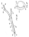
- FIG. 26 through 28 a fourth embodiment of a multiple sample biopsy forceps, substantially similar to the third embodiment (with like parts having numbers incremented by another 200) is shown.
- the tubular member 414 has a proximal end 466, a distal end 468, an irrigation conduit 472, and an aspiration conduit 474.
- the aspiration conduit 474 has a substantially circular cross section, while the irrigation conduit 472 has a generally crescent-shaped cross section.
- a control coupling tube 423 is coupled to the second irrigation coupling tube 425.
- Two pull wires 420, 421 extend through the control coupling tube 423, pass through a substantially fluidtight valve (not shown) coupling the control coupling tube 423 and the second irrigation coupling tube 425, enter into the second irrigation coupling tube 425, and extend through the irrigation conduit 472 to the distal end 468 of the tubular member.
- An aspiration coupling tube 427 is coupled to the aspiration conduit 474.
- the distal assembly 422 of the fourth embodiment includes a stationary jaw 481 bonded to the distal end 468 of the tubular member, and a movable jaw 490 coupled thereto.
- the stationary jaw 481 includes a jaw cup 488, an integral central clevis 493, and ramps 495, 496.
- the jaw cup abuts the distal end of the tubular member and is positioned over the aspiration conduit 474 and preferably has a blunt cutting surface or lip 492.
- the central clevis 493 and ramps 495, 496 extend from the stationary jaw 481 and abut and partially cover the irrigation conduit 474.
- a movable jaw 490 preferably made of metal, is provided with a sharp cutting edge 498, defines two jaw holes 402, 404 for receiving a pull wire 420, and is provided with two bosses 512, 514 for mounting the jaw.
- the bosses 512, 514 loosely engage the central clevis 493 and a pivot pin 494 extends through the bosses and the central clevis.
- the ramps form entrances 499, 500 for the pull wires.
- the movable jaw 490 rides on the proximal ramps 495, 496 when moving from an open to a closed position.
- the pull wires 420, 421 are coupled to the jaw holes 502, 504 by a Z-bend 506, 507 and extend through the entrances 499, 500 into the irrigation conduit 472, through a portion of the second irrigation coupling tube 425, and further into a control coupling tube 423 coupled thereto.
- the entrances 499, 500 are sufficiently small that only an insubstantial amount of fluid exits from the irrigation conduit when the jaws are in a closed position and irrigant is forced through the irrigation conduit 474 to the distal assembly.
- the tubular member 614 is preferably a multi-lumen extrusion co-extruded with support wires 676, 677, 678.
- the tubular member 614 has two irrigation conduits 672, 673, and an aspiration conduit 674.
- the aspiration conduit 674 has a substantially circular cross section, and the irrigation conduits 672, 673 have a generally ovoid cross section.
- the extrusion is preferably made of a polymer (e.g., polyurethane, a polyether block amide, polyethylene, or PVC) or another bondable material.
- a pull wire 620, 621 extends through each irrigation conduit 672, 673.
- the preferred diameter for the tubular member 614 is approximately 2.8 - 3.3 mm
- the preferred diameter for the aspiration conduit 674 is approximately 1.5 mm
- the preferred diameter for each of the support wires 676, 677, 678 is approximately 0.4 mm.
- the support wires are preferably made of stainless steel and are also preferably round, but alternatively may be flat.
- the tubular member of the fifth embodiment is incorporated in a manner substantially similar to the tubular member of the fourth embodiment and several advantages are realized with this embodiment. First, a three support wire co-extrusion provides necessary rigidity to the wall of the aspiration conduit. Second, the three wire co-extrusion is easy to manufacturer.
- the three support wires may be replaced with a single larger high tensile support wire 676a or multiband cable through the tubular member 614a.
- the support wire is preferably located substantially between the two irrigation conduits and the aspiration conduit.
- the single support wire 676a provides necessary support to the aspiration conduit 674a and is also easy to manufacture.
- the entire support wire or just its distal end may be made from a shape memory material, e.g., Nitinol, which will bend in a predetermined manner when heated to a predetermined temperature.
- the shape memory distal end of the support wire can be made to bend in a predetermined manner and consequently the tubular member can be made to bend in a predetermined manner. Tissue samples can thereby be retrieved which are not linearly aligned with the endoscope through which the distal end of the biopsy forceps instrument extends.
- valve means may be provided to individually control aspiration and irrigation. It will also be appreciated that while the valve means has been shown coupled to the proximal actuation handle, the valve means may be separable and/or independent from the proximal actuation handle. Furthermore, while the chamber has been described as being removably coupled to the shaft, it will be appreciated that the chamber may be integral with the shaft or, alternatively, not coupled to the actuation handle. Moreover, the shapes of the chamber and the catch member may be different from that described. In addition, it is not necessary to provide first and second irrigation connectors as a single uninterrupted coupling tube may extend from the irrigation conduit of the tubular member through the valve means.
- actuation means may be of another type well known in the art.
- a laparoscopic type handle sinissor-type
- yet other modifications could be made to the provided invention without deviating from its scope as so claimed.
Description
- This invention relates broadly to endoscopic surgical instruments. More particularly, this invention relates to biopsy forceps instrument with means for facilitating sample removal without withdrawal of the biopsy forceps instrument from an endoscope.
- Endoscopic biopsy procedures are typically performed with an endoscope and an endoscopic biopsy forceps device (bioptome). The endoscope is a long flexible tube carrying fiber optics and having a narrow lumen through which the bioptome is inserted. The bioptome typically includes a long flexible coil having a pair of opposed jaws at the distal end and manual actuation means at the proximal end. Manipulation of the actuation means opens and closes the jaws. During a biopsy tissue sampling operation, the surgeon guides the endoscope to the biopsy site while viewing the biopsy site through the fiber optics of the endoscope. The bioptome is inserted through the narrow lumen of the endoscope until the opposed jaws arrive at the biopsy site. While viewing the biopsy site through the fiber optics of the endoscope, the surgeon positions the jaws around a tissue to be sampled and manipulates the actuation means so that the jaws close around the tissue. A sample of the tissue is then cut and/or torn away from the biopsy site while it is trapped between the jaws of the bioptome. Keeping the jaws closed, the surgeon withdraws the bioptome from the endoscope and then opens the jaws to collect the biopsy tissue sample.
- A biopsy tissue sampling procedure often requires the taking of several tissue samples either from the same or from different biopsy sites. Unfortunately, most bioptomes are limited to taking a single tissue sample, after which the device must be withdrawn from the endoscope and the tissue collected before the device can be used again to take a second tissue sample. Several attempts have been made to provide an instrument which will allow the taking of several tissue samples before the instrument must be withdrawn and the samples collected. Problems in providing such an instrument include the extremely small size required by the narrow lumen of the endoscope and the fact that the instrument must be flexible in order to be inserted through the lumen of the endoscope. Thus, several known multiple sample biopsy instruments are precluded from use with an endoscope because of their size and rigidity. These include the "punch and suction type" instruments disclosed in
U.S. Patents No. 3,989,033 to Halpern et al. and No. 4,522,206 to Whipple et al. Both of these devices have a hollow tube with a punch at the distal end and a vacuum source coupled to the proximal end. A tissue sample is cut with the punch and suctioned away from the biopsy site through the hollow tube. It is generally recognized, however, that dry suctioning tissue samples (i.e., without the use of an irrigating fluid) through a long narrow flexible bioptome is virtually impossible. - Efforts have been made to provide multiple sampling ability to an instrument which must traverse the narrow lumen of an endoscope. These efforts have concentrated on providing a cylindrical storage space at the distal end of the instrument wherein several tissue samples can be accumulated before the instrument is withdrawn from the endoscope.
U.S. Patent No. 4,651,753 to Lifton, for example, discloses a rigid cylindrical member attached to the distal end of a first flexible tube. The cylindrical member has a lateral opening and a concentric cylindrical knife blade is slidably mounted within the cylindrical member. A second flexible tube, concentric to the first tube is coupled to the knife blade for moving the knife blade relative to the lateral opening in the cylindrical member. A third flexible tube having a plunger tip is mounted within the second flexible tube and a vacuum source (a syringe) is coupled to the proximal end of the third tube. A tissue sample is taken by bringing the lateral opening of the cylindrical member upon the biopsy site, applying vacuum with the syringe to draw tissue into the lateral opening, and pushing the second flexible tube forward to move the knife blade across the lateral opening. A tissue sample is thereby cut and trapped inside the cylindrical knife within the cylindrical member. The third flexible tube is then pushed forward moving its plunger end against the tissue sample and pushing it forward into a cylindrical storage space at the distal end of the cylindrical member. Approximately six samples can be stored in the cylindrical member, after which the instrument is withdrawn from the endoscope. A distal plug on the cylindrical member is removed and the six samples are collected by pushing the third tube so that its plunger end ejects the samples. - The device of the Lifton patent suffers from several recognizable drawbacks. First, it is often difficult to obtain a tissue sample laterally of the device. Second, in order to expedite the obtaining of a lateral sample, a syringe is used to help draw the tissue into the lateral opening. However, this causes what was once a two-step procedure (position and cut), to become a three-step procedure (position, suction, cut). In addition, the use of a syringe requires an additional hand. Third, the Lifton patent adds a fourth step to the biopsy procedure by requiring that the tissue sample be pushed into the storage space. Thus, in all, the Lifton patent requires substantial effort on the part of the surgeon and an assistant and much of this effort is involved in pushing tubes, an action which is counter-intuitive to classical biopsy sampling. The preferred mode of operation of virtually all endoscopic tools is that a gripping action at the distal end of the instrument is effected by a similar action at the proximal end of the instrument. Classical biopsy forceps jaws are closed by squeezing a manual actuation member in a syringe-like manner.
- A more convenient endoscopic multiple sample biopsy device is disclosed in
U.S. Patent No. 5,171,255 to Rydell. Rydell provides a flexible endoscopic instrument with a knife-sharp cutting cylinder at its distal end. A coaxial anvil is coupled to a pull wire and is actuated in the same manner as conventional biopsy forceps. When the anvil is drawn into the cylinder, tissue located between the anvil and the cylinder is cut and pushed into a storage space within the cylinder. Several samples may be taken and held in the storage space before the device is withdrawn from the endoscope. While the device of Rydell is effective in providing a multiple sample tool where each sample is obtained with a traditional two-step procedure (position and cut), it is still limited to lateral cutting which is often problematic. Traditional biopsy forceps provide jaws which can grasp tissue frontally or laterally. Even as such, it is difficult to position the jaws about the tissue to be sampled. Lateral sampling is even more difficult. - A multiple sample biopsy forceps of a more traditional form is disclosed in co-owned
U.S. Patent No. 5,542,432 to Slater et al. Slater et al. discloses an endoscopic multiple sample biopsy forceps having a jaw assembly which includes a pair of opposed toothed jaw cups each of which is coupled by a resilient arm to a base member. The base member of the jaw assembly is mounted inside a cylinder and axial movement of one of the jaw assembly and cylinder relative to the other draws the arms of the jaws into the cylinder or moves the cylinder over the arms of the jaws to bring the jaw cups together in a biting action. The arms of the jaws effectively form a storage chamber which extends proximally from the lower jaw cup and prevents accumulated biopsy samples from being squeezed laterally out from between the jaws during repeated opening and closing of the jaws and the lower jaw cup enhances movement of the biopsy samples into the storage chamber. The device can hold up to four samples before it must be retrieved out of the endoscope. However, in some biopsy procedures it is sometimes desirous to retrieve more. In addition, it has been found that samples within the chamber can stick together and make determinations of which sample came from which biopsy site somewhat difficult. -
U.S. Patent No. 5,538,008 to Crowe discloses a multiple sample bioptome which purports to take several samples and to transfer each sample by water pressure through a duct to the proximal end of the instrument, where each sample can be individually retrieved. The device includes a plastic jaw set biased in an open position and coupled to the distal end of an elongate tube, up to seven feet long. The tube defines a duct. A sleeve extends over the tube and a water flow passage is provided between the tube and the sleeve. An aperture is provided in the tube to permit the water flow passage to meet the duct at the distal end of the tube. Withdrawing the tube into the sleeve is disclosed to force the jaws closed and enable a sample to be cut from tissue and lodge in the duct. The water flow passage is disclosed to enable water to flow under pressure from the proximal end of passage to the distal end of the passage, through the aperture and into the distal end of the duct and to be aspirated to the proximal end of the duct, thereby transferring with it any sample contained in the duct to the proximal end where the sample can be retrieved. - While on paper the Crowe device on which the preamble of claim 1 is based is appealing, in practice the design is impractical and flawed. For example, it would be very difficult, if not impossible, to slide the elongate tube, up to seven feet in length, relative to a sleeve of substantially the same length. It would also be difficult to maintain an unobstructed water flow passage between the tube and sleeve as the tube and sleeve curve and bend through the body. Furthermore, in order for the jaws to cut a tissue sample, the tube and jaws must be drawn into the sleeve, thereby undesirably pulling the jaws away from the tissue to be sampled.
- It is therefore an object of the invention to provide an endoscopic biopsy forceps instrument which permits numerous tissue samples to be taken from a patient without removing the forceps from within the patient.
- It is another object of the invention to provide an endoscopic biopsy forceps instrument which can individually retrieve each of several tissue samples from the forceps without removing the forceps from the patient.
- It is also an object of the invention to provide an endoscopic biopsy forceps instrument which aspirates tissue samples contained in the forceps and, in some embodiments, irrigates the forceps.
- It is an additional object of the invention to provide an endoscopic biopsy forceps instrument which includes a proximal actuation handle having a chamber to retain tissue samples aspirated through the instrument.
- It is a further object of the invention to provide an endoscopic biopsy forceps instrument which includes a proximal actuation handle for an endoscopic biopsy forceps instrument which, in some embodiments, includes a control means for controlling the aspiration and irrigation of fluid through the instrument.
- In accord with these objects which will be discussed in detail below, an endoscopic biopsy forceps instrument is provided and generally includes a proximal actuation handle, a distal forceps assembly, a control member coupled to the proximal actuation handle and the distal forceps assembly, an aspiration conduit and, in some embodiments, a flexible multi-lumen tubular member having an irrigation conduit, the aspiration conduit, and a control conduit which receives the control member.
- According to a preferred embodiment of the invention, the proximal actuation handle includes a shaft and a spool slidably mounted on the shaft. The actuation handle is also provided with a proximal irrigation passage, a sample chamber, a sample catch member, and a pinch valve which regulates irrigation and aspiration. The proximal irrigation passage is coupled to the irrigation conduit and to an irrigation coupling tube. The sample chamber is coupled to the aspiration conduit and to an aspiration coupling tube. The sample catch member includes a screen which is inserted into the sample chamber and filters out tissue samples from the aspirated fluid. The irrigation coupling tube and the aspiration coupling tube extend through the pinch valve which operates to control the flow of fluid through the tubes. The actuation handle is coupled to the proximal ends of both the flexible tubular member and the control member and moves the control member relative to the tubular member.
- The distal assembly is coupled to the distal end of the tubular member and includes a hollow jaw cup coupled over the distal end of the aspiration conduit and a hollow movable jaw pivotally coupled adjacent the irrigation conduit. The jaw cup is preferably formed from a hard plastic and has a blunt cutting surface, while the movable jaw is preferably a metal jaw with a sharp cutting edge. The movable jaw is further coupled to the control member, such that actuation of the actuation handle moves the movable jaw relative to the jaw cup, and thereby moves the jaws from an open position to a closed position. Moving the hollow jaws to a closed position provides a substantially fluidtight coupling between the irrigation and aspiration conduits.
- It will be appreciated that the distal end of the instrument is brought into contact with tissue of which a sample is required and the actuation handle is actuated to close the jaws and cut off a tissue sample. With the jaws in a closed position, water is irrigated through the irrigation conduit to the jaws at the distal end of the instrument and aspirated from the jaws to the proximal end of the instrument through the aspiration conduit, such that the sample cut by the jaws is aspirated with the water. As the water is aspirated it passes through the chamber and the sample is filtered onto the screen. The screen may easily be removed to retrieve the sample. It will be further appreciated that the entire procedure of cutting a sample and retrieving the sample may be performed without removing the endoscopic biopsy forceps instrument from its location within the body.
- According to one embodiment not forming part of the invention, the tubular member is ovoid in shape and defines a control conduit, an irrigation conduit, and an aspiration conduit. The distal forceps assembly includes a movable jaw, and a substantially rigid molded collar which is provided with a proximal socket-like coupling means for coupling the tubular member thereto, a fixed jaw cup, a distal irrigation passage, and a control passage. The collar is of similar diameter to the endoscope and is designed to be coupled to the outside of the distal end of an endoscope by a silicone rubber sock. The movable jaw is pivotally mounted on the molded collar and is movable relative to jaw cup. The tubular member is coupled in the socket. A control wire extends through the control conduit and the control passage is coupled to the two holes in the movable jaw.
- According to a second embodiment not forming part of the invention, the biopsy forceps instrument includes a tubular member which defines an aspiration conduit having a circular cross section, an irrigation conduit having a kidney-shaped cross section, and two control conduits. The distal assembly includes a stationary jaw bonded to the distal end of the tubular member, and a movable jaw. The stationary jaw includes a hollow jaw cup, a clevis member and two proximal ramps. The jaw cup is located over the aspiration conduit, and the clevis and the proximal ramps extend from the jaw cup over the irrigation conduit. The movable jaw is coupled to the clevis and is guided along the proximal ramps. The two control conduits exit the distal end of the tubular member lateral of the proximal ramps. A central portion of a control member is coupled to the movable jaw and each end of the control member extends through the control conduits to the proximal end of the instrument.
- According to a third embodiment not forming part of the invention, the instrument includes a tubular member which defines an aspiration conduit having a circular cross section and an irrigation conduit having a crescent-shaped cross section. The distal assembly is substantially similar to the second embodiment. The proximal ramps abut and partially cover the irrigation conduit to define two entrances into the irrigation conduit for the control members. A distal end of each control member is coupled to the movable jaw and the control members extend through the entrances and into the irrigation conduit. The entrances are sufficiently small such that when the jaws are in a closed position and fluid is irrigated through the irrigation conduit to the distal assembly, substantially all of the fluid passes through the irrigation conduit and into the jaws; i.e. only an insubstantial amount of the fluid irrigated through the irrigation conduit exits through the entrances formed by the ramps.
- Additional objects and advantages of the invention will become apparent to those skilled in the art upon reference to the detailed description taken in conjunction with the provided figures. The first, third, fourth and fifth embodiments do not form part of the invention but are included to aid the understanding thereof.
-
-
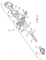
Figure 1 is a broken perspective view of a first embodiment of an endoscopic biopsy forceps instrument ; -
Figure 2 is a broken perspective view of the proximal end of the first embodiment ; -
Figure 3 is a broken perspective view of the sample chamber of the first embodiment ; -
Figure 4 is a perspective view of the front side of the sample catch member of the first embodiment -
Figure 5 is a perspective view of the back side of the sample catch member of the first embodiment ; -
Figure 6 is an enlarged broken perspective view of the tubular member of the first embodiment; -
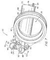
Figure 7 is an enlarged broken perspective view of the distal assembly of the first embodiment with the jaws in an open position; -
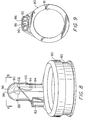
Figure 8 is an enlarged broken perspective view of the distal assembly of the first embodiment with the jaws in a closed position; -
Figure 9 is a bottom end view ofFigure 8 ; -
Figure 10 is a cross section across line 10-10 ofFigure 7 ; -
Figure 11 is cross section across line 11-11 ofFigure 8 ; -
Figure 12 is a broken perspective view of the distal assembly of the first embodiment illustrating an alternate control member configuration; -
Figure 13 is a broken perspective view of the distal assembly of the first embodiment illustrating another alternate control member configuration; -
Figure 14 is a front elevation view of a sample catch assembly according to a second embodiment, which is according to the invention; -
Figure 15 is a top view of the sample catch assembly according to the second embodiment ; -
Figure 16 is cross section view through line 16-16 inFigure 14 ; -
Figure 17 is a side elevation view of the sample catch assembly according to the second embodiment ; -
Figure 18 is a front elevation view of the sample tray of the sample catch assembly according to the second embodiment; -
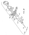
Figure 19 is a broken perspective view of a third embodiment of an endoscopic biopsy forceps instrument ; -
Figure 20 is an enlarged broken transparent perspective view of the tubular member of the third embodiment ; -
Figure 21 is an enlarged cross section across line 21-21 ofFigure 20 ; -
Figure 22 is an enlarged broken perspective view of the distal assembly of the third embodiment with the jaws in an open position; -
Figure 23 is a cross section across line 23-23 ofFigure 22 ; -
Figure 24 is an enlarged broken perspective view of the distal end of the third embodiment with the biopsy jaws in a closed position; -
Figure 25 is a cross section across line 25-25 ofFigure 24 ; -
Figure 26 is an enlarged broken transparent perspective view of the tubular member of a fourth embodiment ; -
Figure 27 is an enlarged cross-section across line 27-27 ofFigure 26 ; -
Figure 28 is a enlarged broken perspective view of the distal end of the fourth embodiment with the jaws in an open position; -
Figure 29 is a cross-section of a tubular member according to a fifth embodiment; and -
Figure 30 is a cross-section of a tubular member according to a sixth embodiment . - Turning now to
Figure 1 , a multiple samplebiopsy forceps instrument 10 is shown. The biopsy forceps instrument generally includes aproximal actuation handle 12, a flexible multi-lumentubular member 14, apull wire 20, and adistal assembly 22. Several coupling tubes are preferably provided to couple the proximal actuation handle 12 to thetubular member 14 and to irrigation and aspiration means. In particular, acontrol coupling tube 23, first and secondirrigation coupling tubes aspiration coupling tubes - The proximal actuation handle 12 includes a
shaft 30 having atransverse slot 32 and aspool 34 slidably mounted on the shaft and having a transverse bar (not shown) extending through theslot 32, as is common in the art. The actuation handle 12 is provided with apinch valve 45 which regulates irrigation and aspiration and a sample catch assembly 41 which includes asample chamber 42 and asample catch member 44. Turning toFigures 2 and 3 , thesample chamber 42 includesirrigation connectors irrigation coupling tube 24 to the secondirrigation coupling tube 25. Thesample chamber 42 also includes first andsecond aspiration connectors aspiration coupling tube 26 to the secondaspiration coupling tube 27. As shown inFigure 3 , the diameter of thechamber 42 is significantly larger than the diameter of the first (and second) aspiration coupling tubes 26 (,27). As also shown inFigure 3 , thechamber 42 includes asample catch connector 43 for removably coupling the chamber to a distal portion of theshaft 30. Thesample catch connector 43 is preferably T-shaped for mating with a slot (not shown) on theshaft 30, but may be otherwise shaped for connection to the shaft. Referring toFigures 3 through 5 , thesample catch member 44 includes ahandle portion 52, anengagement portion 54 which removably engages thesample catch member 44 to thesample chamber 42, and ascreen 56. Thescreen 56 extends through thesample chamber 42 between the first andsecond aspiration connectors screen 56 includes afront side 58 and aback side 60 and is provided with a plurality ofperforations 62 which are preferably frustoconical in shape and expand from thefront side 58 to theback side 60. As further shown inFigures 3 through 5 , theengagement portion 54 and the opening of thesample chamber 42 preferably have irregular shaped cross-sections which enable the engagement of theengagement portion 54 into thesample chamber 42 in one orientation only. As a result, thefrustoconical perforations 62 of thescreen 56 can be easily aligned in the proper front to back orientation. - As shown in
Figure 2 , the firstirrigation coupling tube 26 and the firstaspiration coupling tube 27 extend through thepinch valve 45 which operates to control the flow of fluid through thetubes irrigation coupling tube 26 and the firstaspiration coupling tube 27, i.e, to collapse the tubes on top of each other. Pressing downward on thepinch valve 45 with a practitioner's finger counters the bias of the pinch valve to permit fluid flow through the firstirrigation coupling tube 26 and the firstaspiration coupling tube 27. - Turning to
Figures 6 and7 , and in accord with the first embodiment, thetubular member 14 is preferably an ovoid multi-lumen extrusion. The tubular member includes aproximal end 66, adistal end 68, acontrol conduit 70, anirrigation conduit 72, and anaspiration conduit 74, each of which extends through the tubular member to thedistal assembly 22. At theproximal end 66 of the tubular member, thecontrol conduit 70 is coupled to thecontrol coupling tube 23, theirrigation conduit 72 is coupled to the secondirrigation coupling tube 25 and theaspiration conduit 74 is coupled to the secondaspiration coupling tube 27. - Referring to
Figures 7 through 9 , thedistal assembly 22 includes a substantially rigid moldedcollar 80 and a hollowmovable jaw 90. Thecollar 80 is preferably made from a unitary piece of polycarbonate, a glass-filled polycarbonate, a hard grade styrene, or other plastic, while themovable jaw 90 is preferably made from cast metal. The collar includes acentral opening 81, acircumferential channel 83, a distally extendingcontrol passage 82, a distally extendinghollow jaw mount 84, a distally extending hollowstationary jaw 88, and aproximal socket 86. Thecentral opening 81 of thecollar 80 is of similar diameter to the outer diameter of the endoscope and is designed to couple the collar to the outside of the distal end of an endoscope. Thecircumferential channel 81 receives a portion of a silicone rubber sock (not shown), which is used to secure thecollar 80 to the endoscope. - The
stationary jaw 88 preferably includes a blunt edge orlip 92. Themovable jaw 90 is pivotally mounted at apivot 94 on thejaw mount 84 and is pivotable relative tostationary jaw 88. Themovable jaw 90 is preferably provided with asharp cutting edge 98, astop 100 for limiting the extent to which the movable jaw pivots away from thestationary jaw 88, and twojaw holes pull wire 20, as described below. - Referring to
Figures 9 through 11 , theproximal socket 86 is aligned with thecontrol passage 82, thejaw mount 84 and thestationary jaw 88, and is designed to receive thedistal end 68 of theflexible tubular member 14. Thedistal end 68 of the tubular member is secured in theproximal socket 86, preferably using an adhesion bonding agent, such that thecontrol passage 82 is coupled to thecontrol conduit 70, thejaw mount 84 is coupled substantially fluidtight to theirrigation conduit 74, and thestationary jaw 88 is coupled substantially fluidtight to the aspiration conduit 76. - Turning back to
Figures 1 ,6 , and11 , a central portion of thepull wire 20 extends through the jaw holes 102, 104 and the ends of thepull wire 20 extend through thecontrol passage 82, thecontrol conduit 74, and thecontrol coupling tube 23 to thespool 34. Referring toFigure 12 , alternatively the pull wire 20a forms asecure loop 106a through thejaw holes twist 108a. Referring toFigure 13 , in yet another alternative, two pullwires jaw hole bend 110b, 112b and extending through thecontrol passage 82b. - Referring to
Figures 1 ,7 , and8 , it will be appreciated that movement of thespool 34 relative to theshaft 30 results in movement of thepull wire 20 relative to thetubular member 14 and consequently moves themovable jaw 90 relative to thestationary jaw 88 such that the jaws open (Figure 7 ) and close (Figure 8 ). Referring toFigures 7 through 11 , when the stationary andmovable jaws stationary jaw 88 is coupled to theaspiration conduit 70 and themovable jaw 90 is coupled over theirrigation conduit 72, a substantially fluidtight coupling of the irrigation and aspiration conduits is achieved. - In use, it will be appreciated that the distal end of the endoscope to which the
collar 80 is coupled is maneuvered adjacent the desired tissue for sampling and the distal assembly is brought into contact with tissue 110 (Figures 10 and 11 ). The actuation handle 12 is actuated to close thejaws tissue sample 112. When thejaws aspiration coupling tube pinch valve 45 by depressing the pinch valve. Irrigating fluid is thereby permitted to flow through the first and second proximalirrigation coupling tubes irrigation conduit 70 and thehollow jaw mount 84, and to thejaws Figures 2 through 6 , as the water is aspirated through theaspiration conduit 74 and into thesample chamber 42, the sample is filtered onto thescreen 58. The frustoconical shape of theperforations 62 permits increased fluid flow through the perforate screen while preventing the tissue sample from passing through the screen. Irrigation and aspiration means are interrupted by releasing thepinch valve 45 such that the pinch valve clamps down on the first proximal irrigation andaspiration coupling tubes screen 58 may easily be removed to retrieve the sample by gripping thehandle portion 52 of thesample catch member 44 and pulling the sample catch member from thesample chamber 42. The sample is recovered from the screen, and the sample catch member is reinserted into the sample chamber to continue the procedure. It will be further appreciated that the entire procedure of cutting a sample and retrieving the sample may be performed without removing the endoscopic multiple sample biopsy forceps instrument from its location within the body. Unlimited subsequent samples may be obtained in an identical manner. - A second embodiment of the proximal actuation handle which is according to the invention is also provided, substantially similar to the first embodiment. Referring to
Figures 14 to 18 , the second embodiment has an alternatesample catch assembly 900 able to receive and keep separate samples without necessitating the removal of a sample catch between each sample retrieval. Thesample catch assembly 900 generally includes asample tray holder 902 having front andrear walls sample tray 904 situated in the tray holder between the front and rear walls, and a threadedconnector 906 extending through thefront wall 908 of thetray holder 902 and thetray 904 and removably threaded into the rear wall. Thetray 904 is rotatable about the threadedconnector 906 and relative to thetray holder 902. The threaded connector preferably includes anenlarged head 912 for easier manipulation by a practitioner's fingers. - The
front wall 908 of thetray holder 902 includes a first bore 916 (seeFig. 16 ) through which extends the threadedconnector 906, aninside surface 917, and afirst aspiration connector 918 which extends through thefront wall 908 to theinside surface 917. Therear wall 910 is provided with asecond bore 920, preferably threaded, into which the threadedconnector 906 is secured, and asample catch connector 926 which removably couples thesample catch assembly 900 to a distal portion of theshaft 30. The rear wall is also provided with aninside surface 921, asecond aspiration connector 922, and aproximal aspiration conduit 924 extending from theinside surface 921 to thesecond aspiration connector 922. Thetray holder 902 is also preferable provided withirrigation connectors irrigation coupling tube 24 to the secondirrigation coupling tube 25. - The
tray 904, preferably polygonally shaped, includes anaxial bore 927 and a plurality of chambers orcups 928a-h (indexed 1 through 8, respectively, inFig. 18 ). Referring toFigures 16 and 18 , eachcup 928a-h has a filter orscreen 930a-h and tapers to anoutlet 932a-h (932a, 932e shown inFig. 16 ) proximal of the screen. The screen preferably has frustoconical perforations. Thetray 904 is rotatable within thetray holder 902 such that each of thecups 928a-h is positionable between thefirst aspiration connector 918 and theproximal aspiration conduit 924 for receiving a tissue sample. Thecups 928a-h are maintained in position by providing indentations 934a-h in thetray 904 which receives aprotruberance 935 on theinside surface 921 of the rear wall 910 (seeFig. 15 and17 ); i.e., a cup (for example, 928a) is held is position until sufficient force is provided to thetray 904 to rotate the tray and thereby position the next cup (for example, 928b) for receiving a tissue sample. Each of the cups may thereby be positioned to receive a tissue sample without necessitating the removal of a screen between retrieving individual tissue samples. Alternatively, or in conjunction with the indentations 934a-h and theprotruberance 935, a ratchet mechanism (not shown) can be provided to prevent rotation of a tray opposite to a predetermined direction. Preferably astop 936 is also provided on thetray 904 to prevent the tray from being rotated through more than one cycle without first retrieving the samples received in the cups; i.e., to prevent contamination of an earlier retrieved sample by a later retrieved sample. The tray is also preferably provided with indicia 938 to indicate to the practitioner which cup is currently positioned to receive a sample. - After an individual sample has been received into a first cup, according to a similar method as described above with respect to the first embodiment, the aspiration and irrigation are interrupted and the
tray 904 is rotated such that the next cup is positioned between thefirst aspiration connector 918 and theproximal aspiration conduit 924. The process is repeated after each sample is received into a cup. Once the practitioner has obtained all of the desired samples, or once each cup of the tray contains a sample, the threadedconnector 906 is uncoupled and the tray is removed and the samples may be removed from the cups of the tray. Index numbers adjacent the cups indicate the order in which the samples were retrieved. - Turning to
Figure 19 and20 , a third embodiment of a multiple samplebiopsy forceps instrument 210 is shown. The instrument includes aproximal actuation handle 212, a flexible multi-lumentubular member 214, apull wire 220, and adistal assembly 222. Several coupling tubes are preferably provided to couple theproximal actuation handle 212 to thetubular member 214 and to irrigation and aspiration means. In particular, a Y-shapedcontrol coupling tube 223, first and secondirrigation coupling tubes aspiration coupling tubes - The
proximal actuation handle 212 is substantially similar to the first embodiment (with like parts having numbers incremented by 200). Referring toFigure 20 ,21 and22 , thetubular member 214 is preferably a multi-lumen multi-layer extrusion, and preferably includes afirst metal braid 276 beneath the outermost layer to add desired stiffness to the tubular member. If desired, asecond metal braid 277 may be additionally provided around theaspiration conduit 274 to stiffen and support theaspiration conduit 274. Thetubular member 214 has aproximal end 266, adistal end 268, twocontrol conduits irrigation conduit 272, and anaspiration conduit 274, each of theconduits distal assembly 222. Theaspiration conduit 274 has a substantially circular cross section. Theirrigation conduit 272 has a generally kidney-shaped cross section and is separated from theaspiration conduit 274 by amembrane 275. Thecontrol conduits membrane 275. - Referring to
Figures 22 through 25 , thedistal assembly 222 according to the third embodiment includes astationary jaw 281 coupled, preferably by adhesion bonding, to thedistal end 268 of the tubular member. Thestationary jaw 281, preferably made of plastic, includes ajaw cup 288, an integralcentral clevis 293 and integralproximal ramps jaw cup 288 is located over theaspiration conduit 274 and preferably has a blunt cutting surface orlip 292. Thecentral clevis 293 andproximal ramps stationary jaw 281 and abut and partially cover the irrigation conduit. Amovable jaw 290, preferably made of metal, is provided with asharp cutting edge 298, defines twojaw holes pull wire 220, and is provided with twobosses bosses central clevis 293 and apivot pin 294 extends through the bosses and the central clevis. Theramps stationary jaw 281 guide themovable jaw 290 when opening and closing and assist to form a substantially fluidtight passage between themovable jaw 290 and thestationary jaw cup 288 when the jaws are in a closed position. A central portion of thepull wire 220 which is perpendicular to the longitudinal axis of the instrument extends through the jaw holes 302, 304 and the ends of the pull wire extend into thecontrol conduits Figure 20 , the Y-shapedcoupling tube 223 facilitates alignment of the ends of thepull wire 220 for coupling the pull wire to the proximal actuation handle. Thepull wire 220 may be coated, e.g., in a plastic, to inhibit the pull wire from cutting into the tubular member. - Referring to
Figures 23 and 25 , thedistal end 268 of the tubular member is inserted through the lumen of an endoscope to a biopsy site. Thejaws aspiration conduits Figures 23 and 25 that theirrigation conduit 272 is obstructed at the distal end byclevis 293, it will be appreciated that theirrigation conduit 272 is substantially wider than the clevis and that fluid may flow around the clevis to theaspiration conduit 274. - Turning now to
Figures 26 through 28 , a fourth embodiment of a multiple sample biopsy forceps, substantially similar to the third embodiment (with like parts having numbers incremented by another 200) is shown. Thetubular member 414 has aproximal end 466, adistal end 468, anirrigation conduit 472, and anaspiration conduit 474. Theaspiration conduit 474 has a substantially circular cross section, while theirrigation conduit 472 has a generally crescent-shaped cross section. Acontrol coupling tube 423 is coupled to the secondirrigation coupling tube 425. Twopull wires control coupling tube 423, pass through a substantially fluidtight valve (not shown) coupling thecontrol coupling tube 423 and the secondirrigation coupling tube 425, enter into the secondirrigation coupling tube 425, and extend through theirrigation conduit 472 to thedistal end 468 of the tubular member. Anaspiration coupling tube 427 is coupled to theaspiration conduit 474. - Referring to
Figure 28 , thedistal assembly 422 of the fourth embodiment includes astationary jaw 481 bonded to thedistal end 468 of the tubular member, and amovable jaw 490 coupled thereto. Thestationary jaw 481 includes ajaw cup 488, an integralcentral clevis 493, and ramps 495, 496. The jaw cup abuts the distal end of the tubular member and is positioned over theaspiration conduit 474 and preferably has a blunt cutting surface orlip 492. Thecentral clevis 493 andramps stationary jaw 481 and abut and partially cover theirrigation conduit 474. Amovable jaw 490, preferably made of metal, is provided with asharp cutting edge 498, defines two jaw holes 402, 404 for receiving apull wire 420, and is provided with twobosses bosses central clevis 493 and apivot pin 494 extends through the bosses and the central clevis. By partially covering the irrigation conduit, the ramps formentrances movable jaw 490 rides on theproximal ramps pull wires bend entrances irrigation conduit 472, through a portion of the secondirrigation coupling tube 425, and further into acontrol coupling tube 423 coupled thereto. Theentrances irrigation conduit 474 to the distal assembly. - Turning to
Figure 29 , a fifth embodiment, substantially similar to the fourth embodiment (with like parts having numbers incremented by 200) is shown. Thetubular member 614 is preferably a multi-lumen extrusion co-extruded withsupport wires tubular member 614 has twoirrigation conduits aspiration conduit 674. Theaspiration conduit 674 has a substantially circular cross section, and theirrigation conduits pull wire irrigation conduit tubular member 614 is approximately 2.8 - 3.3 mm, the preferred diameter for theaspiration conduit 674 is approximately 1.5 mm, and the preferred diameter for each of thesupport wires - Turning to
Figure 30 , it will be further appreciated that the three support wires may be replaced with a single larger hightensile support wire 676a or multiband cable through thetubular member 614a. The support wire is preferably located substantially between the two irrigation conduits and the aspiration conduit. Thesingle support wire 676a provides necessary support to the aspiration conduit 674a and is also easy to manufacture. Moreover, the entire support wire or just its distal end may be made from a shape memory material, e.g., Nitinol, which will bend in a predetermined manner when heated to a predetermined temperature. As a result, by heating the support wire to a predetermined temperature, e.g., by applying a current thereto, the shape memory distal end of the support wire can be made to bend in a predetermined manner and consequently the tubular member can be made to bend in a predetermined manner. Tissue samples can thereby be retrieved which are not linearly aligned with the endoscope through which the distal end of the biopsy forceps instrument extends. - There have been described and illustrated herein several embodiments of a multiple sample endoscopic biopsy instrument. While particular embodiments of the invention have been described, it is not intended that the invention be limited thereto, as it is intended that the invention be as broad in scope as the claims will allow and that the specification be read likewise. Therefore, while a particular manner of coupling the proximal actuation handle to the tubular member has been disclosed for the several embodiments, it will be appreciated that other manners of coupling the proximal and distal assemblies may be used as well. In addition, while a pinch valve is described for regulating aspiration and irrigation through the tubular member, it will be appreciated that other valve means may likewise be used to the same effect. Also, it will be appreciated that separate valve means may be provided to individually control aspiration and irrigation. It will also be appreciated that while the valve means has been shown coupled to the proximal actuation handle, the valve means may be separable and/or independent from the proximal actuation handle. Furthermore, while the chamber has been described as being removably coupled to the shaft, it will be appreciated that the chamber may be integral with the shaft or, alternatively, not coupled to the actuation handle. Moreover, the shapes of the chamber and the catch member may be different from that described. In addition, it is not necessary to provide first and second irrigation connectors as a single uninterrupted coupling tube may extend from the irrigation conduit of the tubular member through the valve means. Furthermore, while a spool and shaft type actuation means has been disclosed which moves the pull wire(s) relative to the tubular member, it will be appreciated that the actuation means may be of another type well known in the art. For example, a laparoscopic type handle (scissor-type) may also be used. It will therefore be appreciated by those skilled in the art that yet other modifications could be made to the provided invention without deviating from its scope as so claimed.
Claims (11)
- A biopsy forceps instrument for retrieving a tissue sample from a patient, comprising:a) a flexible tubular member (14) having proximal and distal ends;b) aspiration conduit means (74) for providing a conduit through which the tissue sample can be aspirated from the patient;c) a distal end effector assembly (22) coupled to said distal end of said flexible tubular member;d) at least one pull wire (20) extending through said tubular member;e) a proximal actuation handle (12) including:i) a stationary member (30) coupled to a first of said flexible tubular member and said at least one pull wire;ii) a movable member (34) movable relative to said stationary member and coupled to a second of said flexible tubular member and said at least one pull wire, wherein movement of said movable member relative to said stationary member moves said at least one pull wire relative to said flexible tubular member and actuates said distal end effector assembly so as to obtain the tissue sample; andf) chamber means (900) coupled to said aspiration conduit means for receiving the sample from said aspiration conduit and for retaining the sample, characterised in that said chamber means is coupled to said proximal actuation handle and has a plurality of chambers (928a-h) for discretely storing a plurality of tissue samples.
- A biopsy forceps instrument according to claim 1, further comprising:i) irrigation conduit means (72) providing a conduit thorough which irrigation fluid is provided to the distal end of the flexible tubular member; and/orii) valve means (45) through which said aspiration conduit means, and/or said irrigation conduit means extends.
- A biopsy forceps instrument according to claim 1 or claim 2, wherein said chamber means includes a sample catch arrangement (904) removable from said chamber means, said sample catch arrangement being provided with said plurality of chambers.
- A biopsy forceps instrument according to any preceding claim, wherein said chamber means is provided with a filter or screen arrangement (930a-h) for filtering fluid from the sample, preferably wherein said plurality of chambers are provided with respective filters or screens.
- A biopsy forceps instrument according to claim 3 or claim 4, wherein said chamber means comprises a sample catch arrangement including a sample tray (904) provided with said plurality of sample chambers, said sample tray being received in a sample tray holder (902), and preferably removable from said sample tray holder.
- A biopsy forceps instrument according to claim 5, wherein said sample tray is re-orientatable relative to said chamber means (preferably rotationally about a rotational axis).
- A biopsy forceps instrument according to claim 6, wherein said sample tray is re-orientatable to index or move successive chambers into position for receiving a sample from said aspiration conduit means.
- A biopsy forceps instrument according to claim 6 or claim 7, wherein the catch arrangement includes:i) a stop or ratchet arrangement (934a-h, 935) providing positive positional location of the sample tray with successive respective chambers of said plurality of chambers in position for receiving a sample from said aspiration conduit; and/orii) indicia (938) related to said plurality of chambers, said indicia indicating which of the chambers is positioned to receive a sample from the aspiration conduit means; and/oriii) stop means (936) to prevent the tray from being rotated through more than one cycle.
- A biopsy forceps instrument according to any of claims 5 to 8, wherein said sample tray is polygonally shaped and rotational about an axis.
- A biopsy forceps instrument according to any preceding claim, wherein said plurality of chambers comprise respective cups, respective said cups tapering to a respective outlet (932a-h) and being provided with a respective screen or filter (930a-h).
- A biopsy forceps instrument according to any preceding claim, wherein said chamber means is re-orientatable to move or index successive chambers into position for receiving a sample from said aspiration conduit means.
Applications Claiming Priority (3)
| Application Number | Priority Date | Filing Date | Title |
|---|---|---|---|
| US794352 | 1997-02-03 | ||
| US08/794,352 US6142956A (en) | 1996-11-25 | 1997-02-03 | Proximal actuation handle for a biopsy forceps instrument having irrigation and aspiration capabilities |
| EP98904786A EP0966229B1 (en) | 1997-02-03 | 1998-02-03 | Tubular member for a biopsy forceps instrument having irrigation and aspiration capabilities |
Related Parent Applications (2)
| Application Number | Title | Priority Date | Filing Date |
|---|---|---|---|
| EP98904786A Division EP0966229B1 (en) | 1997-02-03 | 1998-02-03 | Tubular member for a biopsy forceps instrument having irrigation and aspiration capabilities |
| EP98904786.5 Division | 1998-08-06 |
Publications (3)
| Publication Number | Publication Date |
|---|---|
| EP1419740A2 EP1419740A2 (en) | 2004-05-19 |
| EP1419740A3 EP1419740A3 (en) | 2006-02-08 |
| EP1419740B1 true EP1419740B1 (en) | 2010-04-07 |
Family
ID=25162402
Family Applications (2)
| Application Number | Title | Priority Date | Filing Date |
|---|---|---|---|
| EP04001784A Expired - Lifetime EP1419740B1 (en) | 1997-02-03 | 1998-02-03 | Biospy forceps instrument having aspiration capability |
| EP98904786A Expired - Lifetime EP0966229B1 (en) | 1997-02-03 | 1998-02-03 | Tubular member for a biopsy forceps instrument having irrigation and aspiration capabilities |
Family Applications After (1)
| Application Number | Title | Priority Date | Filing Date |
|---|---|---|---|
| EP98904786A Expired - Lifetime EP0966229B1 (en) | 1997-02-03 | 1998-02-03 | Tubular member for a biopsy forceps instrument having irrigation and aspiration capabilities |
Country Status (7)
| Country | Link |
|---|---|
| US (5) | US6142956A (en) |
| EP (2) | EP1419740B1 (en) |
| JP (1) | JP3517247B2 (en) |
| AU (1) | AU745113B2 (en) |
| CA (2) | CA2430652C (en) |
| DE (2) | DE69827773T2 (en) |
| WO (1) | WO1998033436A1 (en) |
Families Citing this family (151)
| Publication number | Priority date | Publication date | Assignee | Title |
|---|---|---|---|---|
| US5649547A (en) * | 1994-03-24 | 1997-07-22 | Biopsys Medical, Inc. | Methods and devices for automated biopsy and collection of soft tissue |
| US6142956A (en) * | 1996-11-25 | 2000-11-07 | Symbiosis Corporation | Proximal actuation handle for a biopsy forceps instrument having irrigation and aspiration capabilities |
| US6537205B1 (en) | 1999-10-14 | 2003-03-25 | Scimed Life Systems, Inc. | Endoscopic instrument system having reduced backlash control wire action |
| ITCE990004A1 (en) | 1999-10-25 | 2000-01-25 | Mario Immacolato Paternuosto | VALVE FOR BIOPSY FORCEPS IN DIGESTIVE ENDOSCOPY |
| US6602203B2 (en) | 2000-10-13 | 2003-08-05 | Ethicon Endo-Surgery, Inc. | Remote thumbwheel for a surgical biopsy device |
| US6814739B2 (en) | 2001-05-18 | 2004-11-09 | U.S. Endoscopy Group, Inc. | Retrieval device |
| US6908442B2 (en) * | 2001-11-07 | 2005-06-21 | Radi Medical Systems Ab | Bending resistant male connector for a guide wire |
| US7169167B2 (en) * | 2001-12-04 | 2007-01-30 | Scimed Life Systems, Inc. | Endoscopic apparatus and method |
| US7175594B2 (en) * | 2002-01-22 | 2007-02-13 | Foulkes Richard B | Ophthalmic sulcus speculum |
| JP4260024B2 (en) | 2002-03-19 | 2009-04-30 | バード ダブリン アイティーシー リミティッド | Vacuum biopsy device |
| EP1524940B1 (en) | 2002-03-19 | 2011-08-24 | Bard Dublin ITC Limited | Biopsy device and biopsy needle module that can be inserted into the biopsy device |
| US6858014B2 (en) * | 2002-04-05 | 2005-02-22 | Scimed Life Systems, Inc. | Multiple biopsy device |
| US6852108B2 (en) * | 2002-05-14 | 2005-02-08 | Spiration, Inc. | Apparatus and method for resecting and removing selected body tissue from a site inside a patient |
| WO2004075740A1 (en) * | 2003-02-25 | 2004-09-10 | Zeon Corporation | Cut tissue piece recovery device |
| DE10314240A1 (en) | 2003-03-29 | 2004-10-07 | Bard Dublin Itc Ltd., Crawley | Pressure generating unit |
| US7591783B2 (en) | 2003-04-01 | 2009-09-22 | Boston Scientific Scimed, Inc. | Articulation joint for video endoscope |
| US20040199052A1 (en) | 2003-04-01 | 2004-10-07 | Scimed Life Systems, Inc. | Endoscopic imaging system |
| US20050245789A1 (en) | 2003-04-01 | 2005-11-03 | Boston Scientific Scimed, Inc. | Fluid manifold for endoscope system |
| US8118732B2 (en) | 2003-04-01 | 2012-02-21 | Boston Scientific Scimed, Inc. | Force feedback control system for video endoscope |
| US7578786B2 (en) | 2003-04-01 | 2009-08-25 | Boston Scientific Scimed, Inc. | Video endoscope |
| US7588545B2 (en) | 2003-09-10 | 2009-09-15 | Boston Scientific Scimed, Inc. | Forceps and collection assembly with accompanying mechanisms and related methods of use |
| US7942896B2 (en) | 2003-11-25 | 2011-05-17 | Scimed Life Systems, Inc. | Forceps and collection assembly and related methods of use and manufacture |
| US7311674B2 (en) * | 2004-06-28 | 2007-12-25 | Scimed Life Systems, Inc. | End effector assembly cap and tissue removal device and related methods |
| DK1768572T3 (en) | 2004-07-09 | 2008-07-28 | Bard Peripheral Vascular Inc | Length detection system for biopsy device |
| JPWO2006030596A1 (en) * | 2004-09-14 | 2008-05-08 | オリンパス株式会社 | Biological tissue collection instrument, endoscope system, and biological tissue collection method |
| US20060074345A1 (en) * | 2004-09-29 | 2006-04-06 | Hibner John A | Biopsy apparatus and method |
| US8083671B2 (en) | 2004-09-30 | 2011-12-27 | Boston Scientific Scimed, Inc. | Fluid delivery system for use with an endoscope |
| US7241263B2 (en) | 2004-09-30 | 2007-07-10 | Scimed Life Systems, Inc. | Selectively rotatable shaft coupler |
| US7479106B2 (en) | 2004-09-30 | 2009-01-20 | Boston Scientific Scimed, Inc. | Automated control of irrigation and aspiration in a single-use endoscope |
| CA2581079A1 (en) | 2004-09-30 | 2006-04-13 | Boston Scientific Scimed, Inc. | Multi-functional endoscopic system for use in electrosurgical applications |
| CA2581124A1 (en) | 2004-09-30 | 2006-04-13 | Boston Scientific Scimed, Inc. | Adapter for use with digital imaging medical device |
| EP1799096A2 (en) | 2004-09-30 | 2007-06-27 | Boston Scientific Scimed, Inc. | System and method of obstruction removal |
| EP1806090A4 (en) * | 2004-10-05 | 2010-03-03 | Olympus Corp | Endoscope system, bio-specimen storage container, bio-specimen sampling method, and bio-specimen treating method |
| US7850650B2 (en) | 2005-07-11 | 2010-12-14 | Covidien Ag | Needle safety shield with reset |
| US7905857B2 (en) | 2005-07-11 | 2011-03-15 | Covidien Ag | Needle assembly including obturator with safety reset |
| US7828773B2 (en) | 2005-07-11 | 2010-11-09 | Covidien Ag | Safety reset key and needle assembly |
| EP1838229B1 (en) * | 2005-01-20 | 2009-08-26 | Wilson-Cook Medical Inc. | Biopsy forceps |
| US7517321B2 (en) | 2005-01-31 | 2009-04-14 | C. R. Bard, Inc. | Quick cycle biopsy system |
| US8070756B2 (en) * | 2005-04-15 | 2011-12-06 | U.S. Endoscopy Group, Inc. | Polypectomy device and method of use |
| US7846107B2 (en) * | 2005-05-13 | 2010-12-07 | Boston Scientific Scimed, Inc. | Endoscopic apparatus with integrated multiple biopsy device |
| US7762960B2 (en) | 2005-05-13 | 2010-07-27 | Boston Scientific Scimed, Inc. | Biopsy forceps assemblies |
| US8097003B2 (en) | 2005-05-13 | 2012-01-17 | Boston Scientific Scimed, Inc. | Endoscopic apparatus with integrated variceal ligation device |
| JP4700415B2 (en) * | 2005-06-06 | 2011-06-15 | オリンパスメディカルシステムズ株式会社 | Biopsy forceps |
| JP4657021B2 (en) * | 2005-06-16 | 2011-03-23 | オリンパスメディカルシステムズ株式会社 | Tissue capture device, endoscope treatment tool, and endoscope |
| US7731692B2 (en) | 2005-07-11 | 2010-06-08 | Covidien Ag | Device for shielding a sharp tip of a cannula and method of using the same |
| USRE46135E1 (en) | 2005-08-05 | 2016-09-06 | Devicor Medical Products, Inc. | Vacuum syringe assisted biopsy device |
| US8317725B2 (en) * | 2005-08-05 | 2012-11-27 | Senorx, Inc. | Biopsy device with fluid delivery to tissue specimens |
| US7854707B2 (en) | 2005-08-05 | 2010-12-21 | Devicor Medical Products, Inc. | Tissue sample revolver drum biopsy device |
| US7896817B2 (en) * | 2005-08-05 | 2011-03-01 | Devicor Medical Products, Inc. | Biopsy device with manually rotated sample barrel |
| US7867173B2 (en) | 2005-08-05 | 2011-01-11 | Devicor Medical Products, Inc. | Biopsy device with replaceable probe and incorporating vibration insertion assist and static vacuum source sample stacking retrieval |
| US7828748B2 (en) * | 2005-08-05 | 2010-11-09 | Devicor Medical Products, Inc. | Vacuum syringe assisted biopsy device |
| US7662109B2 (en) * | 2006-02-01 | 2010-02-16 | Ethicon Endo-Surgery, Inc. | Biopsy device with replaceable probe incorporating static vacuum source dual valve sample stacking retrieval and saline flush |
| US20080004545A1 (en) * | 2005-08-05 | 2008-01-03 | Garrison William A | Trigger Fired Radial Plate Specimen Retrieval Biopsy Instrument |
| ES2403126T3 (en) | 2005-08-10 | 2013-05-14 | C.R.Bard, Inc. | Multi-sample biopsy device with single insertion |
| JP5102207B2 (en) | 2005-08-10 | 2012-12-19 | シー・アール・バード・インコーポレーテッド | Single-insertion, multiple-sampling biopsy device that can be used with various transport systems and integrated markers |
| JP4955681B2 (en) | 2005-08-10 | 2012-06-20 | シー・アール・バード・インコーポレーテッド | Single insertion multiple sampling biopsy device with linear drive |
| JP4716821B2 (en) * | 2005-08-24 | 2011-07-06 | オリンパスメディカルシステムズ株式会社 | Endoscope system, endoscope treatment tool, and endoscope |
| US8052597B2 (en) | 2005-08-30 | 2011-11-08 | Boston Scientific Scimed, Inc. | Method for forming an endoscope articulation joint |
| DE602006006131D1 (en) * | 2005-10-17 | 2009-05-20 | Olympus Medical Systems Corp | endoscope |
| US7654735B2 (en) | 2005-11-03 | 2010-02-02 | Covidien Ag | Electronic thermometer |
| CN101365388B (en) | 2006-01-12 | 2011-03-23 | 多种活检标本有限责任公司 | A sampling apparatus for taking a number of samples |
| US7967759B2 (en) | 2006-01-19 | 2011-06-28 | Boston Scientific Scimed, Inc. | Endoscopic system with integrated patient respiratory status indicator |
| JP4932266B2 (en) * | 2006-01-31 | 2012-05-16 | オリンパスメディカルシステムズ株式会社 | Endoscope system |
| US7918783B2 (en) | 2006-03-22 | 2011-04-05 | Boston Scientific Scimed, Inc. | Endoscope working channel with multiple functionality |
| US8888684B2 (en) | 2006-03-27 | 2014-11-18 | Boston Scientific Scimed, Inc. | Medical devices with local drug delivery capabilities |
| US8740853B2 (en) | 2006-04-14 | 2014-06-03 | Ethicon Endo-Surgery, Inc. | Endoscopic device and method of packaging |
| US7857827B2 (en) | 2006-04-14 | 2010-12-28 | Ethicon Endo-Surgery, Inc. | Endoscopic device |
| US20070244513A1 (en) * | 2006-04-14 | 2007-10-18 | Ethicon Endo-Surgery, Inc. | Endoscopic device |
| US7998167B2 (en) | 2006-04-14 | 2011-08-16 | Ethicon Endo-Surgery, Inc. | End effector and method of manufacture |
| US7955255B2 (en) | 2006-04-20 | 2011-06-07 | Boston Scientific Scimed, Inc. | Imaging assembly with transparent distal cap |
| US8202265B2 (en) | 2006-04-20 | 2012-06-19 | Boston Scientific Scimed, Inc. | Multiple lumen assembly for use in endoscopes or other medical devices |
| US8197396B2 (en) * | 2006-04-26 | 2012-06-12 | Olympus Medical Systems Corp. | Treatment tool for endoscope and medical procedure |
| EP2061378B1 (en) | 2006-08-21 | 2018-10-03 | C.R.Bard, Inc. | Self-contained handheld biopsy needle |
| DE102006040529A1 (en) | 2006-08-30 | 2008-03-13 | Paul Peschke Gmbh | Surgical grasping forceps |
| EP2086418B1 (en) | 2006-10-06 | 2010-12-29 | Bard Peripheral Vascular, Inc. | Tissue handling system with reduced operator exposure |
| US20100286477A1 (en) * | 2009-05-08 | 2010-11-11 | Ouyang Xiaolong | Internal tissue visualization system comprising a rf-shielded visualization sensor module |
| EP3714798A3 (en) | 2006-10-24 | 2020-12-16 | C. R. Bard, Inc. | Large sample low aspect ratio biopsy needle |
| WO2008067281A1 (en) * | 2006-11-30 | 2008-06-05 | Vance Products Incorporated D/B/A Cook Urological Incorporated | Removable handle for medical device |
| US8480595B2 (en) | 2006-12-13 | 2013-07-09 | Devicor Medical Products, Inc. | Biopsy device with motorized needle cocking |
| US7981049B2 (en) | 2006-12-13 | 2011-07-19 | Devicor Medical Products, Inc. | Engagement interface for biopsy system vacuum module |
| US20140039343A1 (en) * | 2006-12-13 | 2014-02-06 | Devicor Medical Products, Inc. | Biopsy system |
| CN102217954B (en) * | 2006-12-13 | 2013-11-06 | 伊西康内外科公司 | Biopsy device and biopsy sample storing assembly |
| US8702623B2 (en) | 2008-12-18 | 2014-04-22 | Devicor Medical Products, Inc. | Biopsy device with discrete tissue chambers |
| US20130324882A1 (en) | 2012-05-30 | 2013-12-05 | Devicor Medical Products, Inc. | Control for biopsy device |
| US9345457B2 (en) | 2006-12-13 | 2016-05-24 | Devicor Medical Products, Inc. | Presentation of biopsy sample by biopsy device |
| US8251916B2 (en) | 2006-12-13 | 2012-08-28 | Devicor Medical Products, Inc. | Revolving tissue sample holder for biopsy device |
| US7938786B2 (en) | 2006-12-13 | 2011-05-10 | Devicor Medical Products, Inc. | Vacuum timing algorithm for biopsy device |
| US20100198106A1 (en) * | 2007-02-19 | 2010-08-05 | Multi Biopsy Sampling Co. Aps | Biopsy forceps for taking one or more samples |
| US8591521B2 (en) | 2007-06-08 | 2013-11-26 | United States Endoscopy Group, Inc. | Retrieval device |
| US8357104B2 (en) | 2007-11-01 | 2013-01-22 | Coviden Lp | Active stylet safety shield |
| US8454531B2 (en) | 2007-11-20 | 2013-06-04 | Devicor Medical Products, Inc. | Icon-based user interface on biopsy system control module |
| AU2013200958B2 (en) * | 2007-11-20 | 2015-03-12 | Devicor Medical Products, Inc. | Revolving tissue sample holder for biopsy device |
| US7575556B2 (en) * | 2007-11-20 | 2009-08-18 | Ethicon Endo-Surgery, Inc. | Deployment device interface for biopsy device |
| US7806835B2 (en) | 2007-11-20 | 2010-10-05 | Devicor Medical Products, Inc. | Biopsy device with sharps reduction feature |
| US7858038B2 (en) | 2007-11-20 | 2010-12-28 | Devicor Medical Products, Inc. | Biopsy device with illuminated tissue holder |
| US9039634B2 (en) | 2007-11-20 | 2015-05-26 | Devicor Medical Products, Inc. | Biopsy device tissue sample holder rotation control |
| US20090131821A1 (en) * | 2007-11-20 | 2009-05-21 | Speeg Trevor W V | Graphical User Interface For Biopsy System Control Module |
| US8052616B2 (en) | 2007-11-20 | 2011-11-08 | Devicor Medical Products, Inc. | Biopsy device with fine pitch drive train |
| US8241225B2 (en) | 2007-12-20 | 2012-08-14 | C. R. Bard, Inc. | Biopsy device |
| US9370396B2 (en) * | 2007-12-26 | 2016-06-21 | St. Jude Medical, Atrial Fibrillation Division, Inc. | Transition apparatus for use with a medical device having an elongate element |
| US7854706B2 (en) | 2007-12-27 | 2010-12-21 | Devicor Medical Products, Inc. | Clutch and valving system for tetherless biopsy device |
| US8622924B2 (en) * | 2008-02-27 | 2014-01-07 | Devicor Medical Products, Inc. | Needle tip for biopsy device |
| US8382660B2 (en) * | 2008-03-13 | 2013-02-26 | Olympus Medical Systems Corp. | Endoscope system having an endoscope and a tissue-collecting apparatus |
| US20110009694A1 (en) * | 2009-07-10 | 2011-01-13 | Schultz Eric E | Hand-held minimally dimensioned diagnostic device having integrated distal end visualization |
| US20100121139A1 (en) | 2008-11-12 | 2010-05-13 | Ouyang Xiaolong | Minimally Invasive Imaging Systems |
| US9095328B2 (en) * | 2008-12-12 | 2015-08-04 | Boston Scientific Scimed, Inc. | Endoscopes having multiple lumens for tissue acquisition and removal and related methods of use |
| US8267869B2 (en) * | 2008-12-31 | 2012-09-18 | Manua Kea Technologies | Multi-purpose biopsy forceps |
| US8936598B2 (en) * | 2009-01-14 | 2015-01-20 | DePuy Synthes Products, LLC | Spinal disc preparation tool |
| WO2010107424A1 (en) | 2009-03-16 | 2010-09-23 | C.R. Bard, Inc. | Biopsy device having rotational cutting |
| CA2965976C (en) | 2009-04-15 | 2019-05-07 | C.R. Bard, Inc. | Biopsy apparatus having integrated fluid management |
| US8206316B2 (en) | 2009-06-12 | 2012-06-26 | Devicor Medical Products, Inc. | Tetherless biopsy device with reusable portion |
| US9173641B2 (en) | 2009-08-12 | 2015-11-03 | C. R. Bard, Inc. | Biopsy apparatus having integrated thumbwheel mechanism for manual rotation of biopsy cannula |
| US8382791B2 (en) * | 2009-08-28 | 2013-02-26 | The Penn State Research Foundation | Surgical tool |
| US8430824B2 (en) | 2009-10-29 | 2013-04-30 | Bard Peripheral Vascular, Inc. | Biopsy driver assembly having a control circuit for conserving battery power |
| US8283890B2 (en) | 2009-09-25 | 2012-10-09 | Bard Peripheral Vascular, Inc. | Charging station for battery powered biopsy apparatus |
| US8485989B2 (en) | 2009-09-01 | 2013-07-16 | Bard Peripheral Vascular, Inc. | Biopsy apparatus having a tissue sample retrieval mechanism |
| US8597206B2 (en) | 2009-10-12 | 2013-12-03 | Bard Peripheral Vascular, Inc. | Biopsy probe assembly having a mechanism to prevent misalignment of components prior to installation |
| US8845546B2 (en) | 2010-02-18 | 2014-09-30 | Devicor Medical Products, Inc. | Biopsy device tissue sample holder with flow restriction device |
| EP2549931B1 (en) * | 2010-03-24 | 2019-12-04 | United States Endoscopy Group, Inc. | Multiple biopsy device |
| CN103096814B (en) * | 2010-09-10 | 2016-12-28 | 德威科医疗产品公司 | Biopsy device tissue sample holder with removable tray |
| WO2012106187A1 (en) | 2011-01-31 | 2012-08-09 | Boston Scientific Scimed, Inc. | Medical devices having releasable coupling |
| US20120265175A1 (en) * | 2011-04-14 | 2012-10-18 | Medtronic Xomed, Inc. | Malleable instrument for laparoscopic procedures |
| US9326755B2 (en) | 2011-08-26 | 2016-05-03 | Devicor Medical Products, Inc. | Biopsy device tissue sample holder with bulk chamber and pathology chamber |
| EP2790747B1 (en) | 2011-12-16 | 2020-06-17 | Stryker Corporation | Specimen collection cassette and medical/surgical collection system |
| US9877706B2 (en) | 2013-03-15 | 2018-01-30 | Devicor Medical Products, Inc. | Biopsy device |
| ES2875575T3 (en) | 2013-03-20 | 2021-11-10 | Bard Peripheral Vascular Inc | Biopsy device |
| AU2014312360B2 (en) * | 2013-08-28 | 2018-07-26 | Devicor Medical Products, Inc. | Tissue collection assembly for biopsy device |
| US9572591B2 (en) | 2013-09-03 | 2017-02-21 | United States Endoscopy Group, Inc. | Endoscopic snare device |
| US10456120B2 (en) | 2013-11-05 | 2019-10-29 | C. R. Bard, Inc. | Biopsy device having integrated vacuum |
| WO2015077699A1 (en) * | 2013-11-25 | 2015-05-28 | Devicor Medical Products, Inc. | Biopsy device with translating valve assembly |
| US10342579B2 (en) | 2014-01-13 | 2019-07-09 | Trice Medical, Inc. | Fully integrated, disposable tissue visualization device |
| US11547446B2 (en) | 2014-01-13 | 2023-01-10 | Trice Medical, Inc. | Fully integrated, disposable tissue visualization device |
| US9370295B2 (en) | 2014-01-13 | 2016-06-21 | Trice Medical, Inc. | Fully integrated, disposable tissue visualization device |
| KR101996564B1 (en) * | 2014-05-15 | 2019-07-05 | 데비코어 메디컬 프로덕츠, 인코포레이티드 | Biopsy device |
| AU2015100640A4 (en) * | 2014-11-03 | 2015-06-11 | Southern Wire Pty Ltd | Wire Retaining Fence Post |
| CA2984601C (en) | 2015-05-01 | 2022-09-20 | C. R. Bard, Inc. | Biopsy device |
| WO2017027749A1 (en) | 2015-08-11 | 2017-02-16 | Trice Medical, Inc. | Fully integrated, disposable tissue visualization device |
| WO2018129546A1 (en) | 2017-01-09 | 2018-07-12 | United States Endoscopy Group, Inc. | Retrieval device |
| JP6844842B2 (en) * | 2017-03-08 | 2021-03-17 | 学校法人 芝浦工業大学 | Medical forceps and medical forceps system |
| EP3624698A4 (en) | 2017-05-19 | 2021-06-09 | Merit Medical Systems, Inc. | Semi-automatic biopsy needle device and methods of use |
| WO2018213611A1 (en) | 2017-05-19 | 2018-11-22 | Merit Medical Systems, Inc. | Biopsy needle devices and methods of use |
| EP3624699B1 (en) | 2017-05-19 | 2023-10-04 | Merit Medical Systems, Inc. | Rotating biopsy needle |
| EP3664682B1 (en) * | 2017-08-07 | 2021-09-22 | Boston Scientific Scimed, Inc. | Adaptor for an endoscope |
| WO2019191705A1 (en) | 2018-03-29 | 2019-10-03 | Trice Medical, Inc. | Fully integrated endoscope with biopsy capabilities and methods of use |
| NL2021760B1 (en) * | 2018-10-04 | 2020-05-11 | A C Hoogerheide Holding B V | DEVICE FOR CATCHING A POLYP, ASSEMBLY AND USE THEREOF |
| SE542910C2 (en) * | 2018-12-14 | 2020-09-15 | Multi4 Ab | An endosurgical device |
| US10471188B1 (en) | 2019-04-12 | 2019-11-12 | Stryker Corporation | Manifold for filtering medical waste being drawn under vacuum into a medical waste collection system |
| US11318242B2 (en) | 2019-04-12 | 2022-05-03 | Stryker Corporation | Manifold for a medical waste collection system |
| USD956967S1 (en) | 2019-11-11 | 2022-07-05 | Stryker Corporation | Manifold housing for a medical waste collection device |
| USD919799S1 (en) | 2019-11-11 | 2021-05-18 | Stryker Corporation | Manifold housing for a medical waste collection device |
| USD996640S1 (en) | 2019-11-11 | 2023-08-22 | Stryker Corporation | Specimen collection tray |
Family Cites Families (134)
| Publication number | Priority date | Publication date | Assignee | Title |
|---|---|---|---|---|
| US33258A (en) * | 1861-09-10 | Improvement in gas-burners | ||
| US2708437A (en) * | 1952-03-31 | 1955-05-17 | Elizabeth Painter Hutchins | Surgical instrument |
| US3093925A (en) * | 1961-02-06 | 1963-06-18 | Norman A Greene | Bubble making toy |
| FR1311292A (en) * | 1961-10-23 | 1962-12-07 | Levallois Optique Et Prec | Advanced biopsy probe and combination of such probe with an endoscope |
| US3289669A (en) * | 1964-02-25 | 1966-12-06 | Donald J Dwyer | Biopsy capsule arrangement |
| US3401684A (en) * | 1965-12-16 | 1968-09-17 | Weck & Co Edward | Biopsy capsules |
| US3590808A (en) * | 1968-09-04 | 1971-07-06 | Us Catheter & Instr Corp | Biopsy tool |
| US3732858A (en) * | 1968-09-16 | 1973-05-15 | Surgical Design Corp | Apparatus for removing blood clots, cataracts and other objects from the eye |
| US3989049A (en) * | 1973-07-30 | 1976-11-02 | In Bae Yoon | Method of applying an elastic ring to an anatomical tubular structure |
| AR196829A1 (en) * | 1973-12-06 | 1974-02-19 | Halpern D | SURGICAL INSTRUMENT FOR BIOPSIES |
| US3980086A (en) * | 1974-02-28 | 1976-09-14 | Bio-Medicus, Inc. | Fluid conveying surgical instrument |
| US3964468A (en) * | 1975-05-30 | 1976-06-22 | The Board Of Trustees Of Leland Stanford Junior University | Bioptome |
| US3992565A (en) * | 1975-07-07 | 1976-11-16 | Belden Corporation | Composite welding cable having gas ducts and switch wires therein |
| US4014333A (en) * | 1975-09-22 | 1977-03-29 | Mcintyre David J | Instrument for aspirating and irrigating during ophthalmic surgery |
| US4315509A (en) * | 1977-01-10 | 1982-02-16 | Smit Julie A | Insertion and removal catheters and intestinal tubes for restricting absorption |
| GB2022421B (en) * | 1978-06-08 | 1982-09-15 | Wolf Gmbh Richard | Devices for obtaining tissure samples |
| US4215509A (en) * | 1978-07-10 | 1980-08-05 | Design Alliance, Inc. | Animated toy block set |
| US4200111A (en) * | 1978-09-21 | 1980-04-29 | Harris Arthur M | Specimen removal instrument |
| US4445517A (en) * | 1981-09-28 | 1984-05-01 | Feild James Rodney | Suction dissector |
| US4519385A (en) * | 1982-12-01 | 1985-05-28 | Snyder Laboratories, Inc. | Lavage handpiece |
| US4662371A (en) * | 1983-01-26 | 1987-05-05 | Whipple Terry L | Surgical instrument |
| US4522206A (en) * | 1983-01-26 | 1985-06-11 | Dyonics, Inc. | Surgical instrument |
| US4617013A (en) * | 1983-03-14 | 1986-10-14 | Timron Instruments, Incorporated | Method and apparatus for surgical irrigation, aspiration and illumination |
| US4919152A (en) * | 1987-03-02 | 1990-04-24 | Ralph Ger | Method of closing the opening of a hernial sac |
| US4712545A (en) * | 1984-04-05 | 1987-12-15 | Acufex Microsurgical, Inc. | Surgical instrument |
| EP0165472B1 (en) * | 1984-05-18 | 1991-02-06 | Harald Maslanka | Surgical gripping instrument |
| USRE33258E (en) | 1984-07-23 | 1990-07-10 | Surgical Dynamics Inc. | Irrigating, cutting and aspirating system for percutaneous surgery |
| JPS637218Y2 (en) * | 1984-09-28 | 1988-03-01 | ||
| US4651753A (en) * | 1984-10-12 | 1987-03-24 | Jayco Pharmaceuticals | Endoscopic multiple biopsy instrument |
| DD233302A1 (en) * | 1984-12-28 | 1986-02-26 | Univ Berlin Humboldt | SAFETY BIOPSY FORCEPS |
| US4644951A (en) * | 1985-09-16 | 1987-02-24 | Concept, Inc. | Vacuum sleeve for a surgical appliance |
| US4763668A (en) * | 1985-10-28 | 1988-08-16 | Mill Rose Laboratories | Partible forceps instrument for endoscopy |
| US4759349A (en) * | 1986-02-24 | 1988-07-26 | Vitalmetrics, Inc. | Surgical instrument having a heat sink for irrigation, aspiration, and illumination |
| JPS62164010U (en) | 1986-04-09 | 1987-10-19 | ||
| US4693257A (en) * | 1986-05-12 | 1987-09-15 | Markham Charles W | Needle aspiration biopsy device with enclosed fluid supply |
| US4950278A (en) * | 1986-08-06 | 1990-08-21 | Sachse Hans E | Endoscope for removal of tissue |
| DE3630203A1 (en) * | 1986-09-04 | 1988-03-17 | Wisap Gmbh | TISSUE PUNCHING |
| US4681123A (en) * | 1986-10-31 | 1987-07-21 | Valtchev Konstantin L | Chorion biopsy instrument |
| US4893257A (en) * | 1986-11-10 | 1990-01-09 | International Business Machines Corporation | Multidirectional scan and print capability |
| JPS63164935A (en) * | 1986-12-27 | 1988-07-08 | 株式会社東芝 | Suction apparatus of endoscope |
| DE8702446U1 (en) * | 1987-02-18 | 1987-10-08 | Kothe, Lutz, 7760 Radolfzell, De | |
| US4776840A (en) * | 1987-09-28 | 1988-10-11 | Alteron, Inc. | Hand-held medical evacuator and irrigation device |
| DE3736150A1 (en) * | 1987-10-26 | 1989-05-03 | Wolf Gmbh Richard | PLIERS, ESPECIALLY HOOK PUNCH |
| IT1211530B (en) | 1987-11-16 | 1989-11-03 | Consiglio Nazionale Ricerche | AREA OF THE POINT OF ORIGIN OF ARITCATERERE FOR ENDOCARDIC BIOPSY AND MY VENTRICULARS THAT CAN BE USED ALSO FOR THE INDIVIDUAL |
| FR2625428A1 (en) * | 1988-01-05 | 1989-07-07 | Sinergy Sa | MULTIFUNCTIONAL OPERATIVE COELIOSCOPY DEVICE FOR PERFORMING DIFFERENT OPERATIVE GESTURES WITH INTRODUCTION OF INSTRUMENTS |
| JPH0347608Y2 (en) | 1988-04-23 | 1991-10-11 | ||
| US4971067A (en) * | 1988-05-05 | 1990-11-20 | Lee Bolduc | Biopsy instrument with a disposable cutting blade |
| DE8809501U1 (en) * | 1988-07-26 | 1988-11-24 | Schad, Karl, 7201 Kolbingen, De | |
| US4986825A (en) * | 1988-10-11 | 1991-01-22 | Concept, Inc. | Surgical cutting instrument |
| US4966162A (en) * | 1989-01-25 | 1990-10-30 | Wang Ko P | Flexible encoscope assembly |
| US5172700A (en) * | 1989-01-31 | 1992-12-22 | C. R. Bard, Inc. | Disposable biopsy forceps |
| DE3918720A1 (en) * | 1989-06-08 | 1990-12-20 | Wolf Gmbh Richard | RETROGRAD CUTTING HOOK PUNCH |
| US5106364A (en) * | 1989-07-07 | 1992-04-21 | Kabushiki Kaisha Topcon | Surgical cutter |
| CA1337714C (en) * | 1989-07-31 | 1995-12-12 | Karen E. Kullas | Irrigation system for use with endoscopic procedure |
| US5632746A (en) * | 1989-08-16 | 1997-05-27 | Medtronic, Inc. | Device or apparatus for manipulating matter |
| US5085658A (en) * | 1989-09-05 | 1992-02-04 | Percutaneous Technologies | Neurosurgical pathological tissue removing device |
| US5505210A (en) * | 1989-11-06 | 1996-04-09 | Mectra Labs, Inc. | Lavage with tissue cutting cannula |
| US5665100A (en) | 1989-12-05 | 1997-09-09 | Yoon; Inbae | Multifunctional instrument with interchangeable operating units for performing endoscopic procedures |
| US5312400A (en) * | 1992-10-09 | 1994-05-17 | Symbiosis Corporation | Cautery probes for endoscopic electrosurgical suction-irrigation instrument |
| US5431645A (en) | 1990-05-10 | 1995-07-11 | Symbiosis Corporation | Remotely activated endoscopic tools such as endoscopic biopsy forceps |
| US5195958A (en) * | 1990-05-25 | 1993-03-23 | Phillips Edward H | Tool for laparoscopic surgery |
| US5152780A (en) * | 1990-05-31 | 1992-10-06 | Tnco, Inc. | Micro-instrument |
| US5219357A (en) * | 1990-05-31 | 1993-06-15 | Tnco, Inc. | Micro-instrument |
| WO1992007516A1 (en) | 1990-11-05 | 1992-05-14 | Koscher & Würtz Gmbh | Surgical instrument |
| US5171255A (en) * | 1990-11-21 | 1992-12-15 | Everest Medical Corporation | Biopsy device |
| US5082000A (en) * | 1990-11-29 | 1992-01-21 | Applied Medical Technology, Inc. | Biopsy forceps with calde controlled jaws |
| US5209747A (en) * | 1990-12-13 | 1993-05-11 | Knoepfler Dennis J | Adjustable angle medical forceps |
| EP0566694A1 (en) * | 1991-01-09 | 1993-10-27 | EndoMedix Corporation | Method and device for intracorporeal liquidization of tissue and/or intracorporeal fragmentation of calculi during endoscopic surgical procedures |
| EP0500215A1 (en) * | 1991-01-30 | 1992-08-26 | ANGELASE, Inc. | Process and apparatus for mapping of tachyarrhythmia |
| US5147292A (en) * | 1991-02-05 | 1992-09-15 | C. R. Bard, Inc. | Control handle with locking means for surgical irrigation |
| US5125910A (en) * | 1991-02-19 | 1992-06-30 | Dexide, Inc. | Surgical endoscopic suction/irrigation cannula assembly |
| US5217460A (en) * | 1991-03-22 | 1993-06-08 | Knoepfler Dennis J | Multiple purpose forceps |
| US5300087A (en) * | 1991-03-22 | 1994-04-05 | Knoepfler Dennis J | Multiple purpose forceps |
| US5195959A (en) * | 1991-05-31 | 1993-03-23 | Paul C. Smith | Electrosurgical device with suction and irrigation |
| US5503616A (en) * | 1991-06-10 | 1996-04-02 | Endomedical Technologies, Inc. | Collapsible access channel system |
| US5286255A (en) * | 1991-07-29 | 1994-02-15 | Linvatec Corporation | Surgical forceps |
| DE69218688T2 (en) | 1991-07-29 | 1997-07-10 | Smith & Nephew Richards Inc | Pliers |
| US5197968A (en) * | 1991-08-14 | 1993-03-30 | Mectra Labs, Inc. | Disposable tissue retrieval assembly |
| US5160343A (en) * | 1991-09-09 | 1992-11-03 | Dexide, Inc. | Surgical instruments handle and forceps assembly |
| US5635639A (en) * | 1991-09-11 | 1997-06-03 | The Charles Stark Draper Laboratory, Inc. | Micromechanical tuning fork angular rate sensor |
| US5285795A (en) * | 1991-09-12 | 1994-02-15 | Surgical Dynamics, Inc. | Percutaneous discectomy system having a bendable discectomy probe and a steerable cannula |
| US5551448A (en) * | 1991-10-18 | 1996-09-03 | United States Surgical Corporation | Endoscopic surgical instrument for aspiration and irrigation |
| AU656628B2 (en) * | 1991-10-18 | 1995-02-09 | United States Surgical Corporation | Endoscopic surgical instrument for aspiration and irrigation |
| US5160319A (en) | 1991-10-23 | 1992-11-03 | Baxter International Inc. | Dual-lumen oocyte aspiration needle |
| US5197963A (en) * | 1991-12-02 | 1993-03-30 | Everest Medical Corporation | Electrosurgical instrument with extendable sheath for irrigation and aspiration |
| US5433725A (en) * | 1991-12-13 | 1995-07-18 | Unisurge, Inc. | Hand-held surgical device and tools for use therewith, assembly and method |
| US5244459A (en) * | 1992-01-28 | 1993-09-14 | Hill Raymond R | Suction irrigator endoscope |
| US5250056A (en) * | 1992-02-04 | 1993-10-05 | Hasson Harrith M | Forceps-type surgical instrument |
| US5542432A (en) * | 1992-02-18 | 1996-08-06 | Symbiosis Corporation | Endoscopic multiple sample bioptome |
| US5645075A (en) | 1992-02-18 | 1997-07-08 | Symbiosis Corporation | Jaw assembly for an endoscopic instrument |
| US5636639A (en) * | 1992-02-18 | 1997-06-10 | Symbiosis Corporation | Endoscopic multiple sample bioptome with enhanced biting action |
| US5195533A (en) * | 1992-05-08 | 1993-03-23 | Boston Scientific Corporation | Biopsy needle instrument for storing multiple specimens |
| US5186714A (en) * | 1992-05-18 | 1993-02-16 | Yab Revo-Tech Inc. | Multifunctional surgical instrument |
| US5230704A (en) * | 1992-06-26 | 1993-07-27 | Biomedical Dynamics Corporation | Suction/irrigation instrument having reusable handle with disposable fluid path |
| US5251641A (en) * | 1992-07-29 | 1993-10-12 | Hgg Laser Fare, Inc. | Biopsy needle |
| US5312327A (en) * | 1992-10-09 | 1994-05-17 | Symbiosis Corporation | Cautery override safety systems endoscopic electrosurgical suction-irrigation instrument |
| US5314406A (en) * | 1992-10-09 | 1994-05-24 | Symbiosis Corporation | Endoscopic electrosurgical suction-irrigation instrument |
| US5683359A (en) | 1992-11-18 | 1997-11-04 | Symbiosis Corporation | Arthroscopic surgical instruments having suction capability |
| WO1994015533A2 (en) * | 1993-01-18 | 1994-07-21 | John Crowe | Endoscope forceps |
| US5593416A (en) * | 1993-01-26 | 1997-01-14 | Donahue; John R. | Method of using flexible surgical instrument |
| DE69409565T2 (en) * | 1993-01-29 | 1998-10-01 | Smith & Nephew Inc | Swiveling curved instrument |
| US5344428A (en) * | 1993-03-05 | 1994-09-06 | Auburn International, Inc. | Miniature surgical instrument |
| US5318528A (en) * | 1993-04-13 | 1994-06-07 | Advanced Surgical Inc. | Steerable surgical devices |
| US5325866A (en) * | 1993-04-20 | 1994-07-05 | Jacek Krzyzanowski | Flexible biopsy forceps |
| US5419774A (en) * | 1993-07-13 | 1995-05-30 | Scimed Life Systems, Inc. | Thrombus extraction device |
| US5336238A (en) * | 1993-07-19 | 1994-08-09 | Birtcher Medical Systems, Inc. | Surgical instrument capable of disassembly |
| US5601585A (en) * | 1994-02-08 | 1997-02-11 | Boston Scientific Corporation | Multi-motion side-cutting biopsy sampling device |
| US5573008A (en) * | 1993-10-29 | 1996-11-12 | Boston Scientific Corporation | Multiple biopsy sampling coring device |
| JPH09503404A (en) | 1993-09-20 | 1997-04-08 | ボストン・サイエンティフィック・コーポレーション | Multiple biopsy sample collection device |
| US5840044A (en) * | 1993-09-30 | 1998-11-24 | Boston Scientific Corporation | Multiple biopsy sampling forceps |
| US5456689A (en) | 1993-10-13 | 1995-10-10 | Arnold J. Kresch | Method and device for tissue resection |
| US5638827A (en) * | 1994-02-01 | 1997-06-17 | Symbiosis Corporation | Super-elastic flexible jaws assembly for an endoscopic multiple sample bioptome |
| US5871453A (en) * | 1994-02-08 | 1999-02-16 | Boston Scientific Corporation | Moveable sample tube multiple biopsy sampling device |
| US5471992A (en) * | 1994-02-08 | 1995-12-05 | Boston Scientific Corporation | Multi-motion cutter multiple biopsy sampling device |
| US5620458A (en) * | 1994-03-16 | 1997-04-15 | United States Surgical Corporation | Surgical instruments useful for endoscopic spinal procedures |
| US5649547A (en) * | 1994-03-24 | 1997-07-22 | Biopsys Medical, Inc. | Methods and devices for automated biopsy and collection of soft tissue |
| US5526822A (en) * | 1994-03-24 | 1996-06-18 | Biopsys Medical, Inc. | Method and apparatus for automated biopsy and collection of soft tissue |
| US5595185A (en) * | 1994-08-11 | 1997-01-21 | N.M.B. Medical Applications Ltd. | Single puncture multi-biopsy gun |
| US6032673A (en) * | 1994-10-13 | 2000-03-07 | Femrx, Inc. | Methods and devices for tissue removal |
| US5527332A (en) * | 1994-11-02 | 1996-06-18 | Mectra Labs, Inc. | Tissue cutter for surgery |
| US5562102A (en) * | 1994-11-21 | 1996-10-08 | Taylor; Thomas V. | Multiple biopsy device |
| US5643307A (en) * | 1994-12-13 | 1997-07-01 | Symbiosis Corporation | Colposcopic biopsy punch with removable multiple sample basket |
| DE69528953T2 (en) | 1994-12-26 | 2003-07-03 | Adachi Co | Process for cleaning an endoscope using an atomizing device |
| US5575293A (en) * | 1995-02-06 | 1996-11-19 | Promex, Inc. | Apparatus for collecting and staging tissue |
| US5603724A (en) * | 1995-02-13 | 1997-02-18 | Tnco, Inc. | Suction punch |
| US5715832A (en) | 1995-02-28 | 1998-02-10 | Boston Scientific Corporation | Deflectable biopsy catheter |
| US5569299A (en) * | 1995-03-01 | 1996-10-29 | Symbiosis Corporation | Endoscopic urological biopsy forceps |
| US5810876A (en) | 1995-10-03 | 1998-09-22 | Akos Biomedical, Inc. | Flexible forceps device |
| US5683388A (en) | 1996-01-11 | 1997-11-04 | Symbiosis Corporation | Endoscopic bipolar multiple sample bioptome |
| US5817013A (en) * | 1996-03-19 | 1998-10-06 | Enable Medical Corporation | Method and apparatus for the minimally invasive harvesting of a saphenous vein and the like |
| US6142956A (en) * | 1996-11-25 | 2000-11-07 | Symbiosis Corporation | Proximal actuation handle for a biopsy forceps instrument having irrigation and aspiration capabilities |
| US5897507A (en) * | 1996-11-25 | 1999-04-27 | Symbiosis Corporation | Biopsy forceps instrument having irrigation and aspiration capabilities |
| US6017316A (en) | 1997-06-18 | 2000-01-25 | Biopsys Medical | Vacuum control system and method for automated biopsy device |
| US20060167877A1 (en) * | 2004-11-23 | 2006-07-27 | Bowe Bell + Howell Company | Inbound link incoming mail stream |
-
1997
- 1997-02-03 US US08/794,352 patent/US6142956A/en not_active Expired - Lifetime
-
1998
- 1998-02-03 DE DE69827773T patent/DE69827773T2/en not_active Expired - Lifetime
- 1998-02-03 EP EP04001784A patent/EP1419740B1/en not_active Expired - Lifetime
- 1998-02-03 EP EP98904786A patent/EP0966229B1/en not_active Expired - Lifetime
- 1998-02-03 CA CA002430652A patent/CA2430652C/en not_active Expired - Fee Related
- 1998-02-03 JP JP53311798A patent/JP3517247B2/en not_active Expired - Fee Related
- 1998-02-03 CA CA002279195A patent/CA2279195C/en not_active Expired - Fee Related
- 1998-02-03 DE DE69841601T patent/DE69841601D1/en not_active Expired - Lifetime
- 1998-02-03 AU AU62580/98A patent/AU745113B2/en not_active Ceased
- 1998-02-03 WO PCT/US1998/001833 patent/WO1998033436A1/en active IP Right Grant
-
2000
- 2000-06-22 US US09/599,403 patent/US6544194B1/en not_active Expired - Lifetime
-
2002
- 2002-08-27 US US10/228,278 patent/US6832990B2/en not_active Expired - Fee Related
-
2004
- 2004-07-07 US US10/885,021 patent/US7204811B2/en not_active Expired - Fee Related
-
2007
- 2007-03-20 US US11/725,549 patent/US7833167B2/en not_active Expired - Fee Related
Also Published As
| Publication number | Publication date |
|---|---|
| US6832990B2 (en) | 2004-12-21 |
| US7204811B2 (en) | 2007-04-17 |
| JP2000516832A (en) | 2000-12-19 |
| US20040243024A1 (en) | 2004-12-02 |
| EP0966229A1 (en) | 1999-12-29 |
| CA2430652A1 (en) | 1998-08-06 |
| DE69827773T2 (en) | 2005-12-08 |
| JP3517247B2 (en) | 2004-04-12 |
| US7833167B2 (en) | 2010-11-16 |
| US20070270709A1 (en) | 2007-11-22 |
| CA2430652C (en) | 2005-03-29 |
| US20030073928A1 (en) | 2003-04-17 |
| WO1998033436A1 (en) | 1998-08-06 |
| CA2279195C (en) | 2004-03-16 |
| DE69841601D1 (en) | 2010-05-20 |
| DE69827773D1 (en) | 2004-12-30 |
| EP1419740A2 (en) | 2004-05-19 |
| EP0966229B1 (en) | 2004-11-24 |
| CA2279195A1 (en) | 1998-08-06 |
| US6142956A (en) | 2000-11-07 |
| AU6258098A (en) | 1998-08-25 |
| EP1419740A3 (en) | 2006-02-08 |
| AU745113B2 (en) | 2002-03-14 |
| US6544194B1 (en) | 2003-04-08 |
Similar Documents
| Publication | Publication Date | Title |
|---|---|---|
| EP1419740B1 (en) | Biospy forceps instrument having aspiration capability | |
| EP0971633B1 (en) | Biopsy forceps instrument having irrigation and aspiration capabilities | |
| WO1998033436A9 (en) | Proximal actuation handle for a biopsy forceps instrument having irrigation and aspiration capabilities | |
| US7347828B2 (en) | Suction adapter for medical instrument | |
| EP1077645B1 (en) | Biopsy instrument having irrigation and aspiration capabilities | |
| US6110127A (en) | Medical instrument for use in combination with an endoscope | |
| US20120137794A1 (en) | Forceps and collection assembly with accompanying mechanisms and related methods of use | |
| AU775899B2 (en) | Biopsy forceps instrument having irrigation and aspiration capabilities | |
| AU1195602A (en) | Proximal actuation handle for a biopsy forceps instrument having irrigation and aspiration capabilities |
Legal Events
| Date | Code | Title | Description |
|---|---|---|---|
| PUAI | Public reference made under article 153(3) epc to a published international application that has entered the european phase |
Free format text: ORIGINAL CODE: 0009012 |
|
| AC | Divisional application: reference to earlier application |
Ref document number: 0966229 Country of ref document: EP Kind code of ref document: P |
|
| AK | Designated contracting states |
Kind code of ref document: A2 Designated state(s): DE FR GB IE IT NL |
|
| PUAL | Search report despatched |
Free format text: ORIGINAL CODE: 0009013 |
|
| AK | Designated contracting states |
Kind code of ref document: A3 Designated state(s): DE FR GB IE IT NL |
|
| 17P | Request for examination filed |
Effective date: 20060628 |
|
| AKX | Designation fees paid |
Designated state(s): DE FR GB IE IT NL |
|
| GRAP | Despatch of communication of intention to grant a patent |
Free format text: ORIGINAL CODE: EPIDOSNIGR1 |
|
| RTI1 | Title (correction) |
Free format text: BIOSPY FORCEPS INSTRUMENT HAVING ASPIRATION CAPABILITY |
|
| GRAS | Grant fee paid |
Free format text: ORIGINAL CODE: EPIDOSNIGR3 |
|
| GRAA | (expected) grant |
Free format text: ORIGINAL CODE: 0009210 |
|
| AC | Divisional application: reference to earlier application |
Ref document number: 0966229 Country of ref document: EP Kind code of ref document: P |
|
| AK | Designated contracting states |
Kind code of ref document: B1 Designated state(s): DE FR GB IE IT NL |
|
| REG | Reference to a national code |
Ref country code: GB Ref legal event code: FG4D |
|
| REG | Reference to a national code |
Ref country code: IE Ref legal event code: FG4D |
|
| REF | Corresponds to: |
Ref document number: 69841601 Country of ref document: DE Date of ref document: 20100520 Kind code of ref document: P |
|
| REG | Reference to a national code |
Ref country code: NL Ref legal event code: VDEP Effective date: 20100407 |
|
| PG25 | Lapsed in a contracting state [announced via postgrant information from national office to epo] |
Ref country code: NL Free format text: LAPSE BECAUSE OF FAILURE TO SUBMIT A TRANSLATION OF THE DESCRIPTION OR TO PAY THE FEE WITHIN THE PRESCRIBED TIME-LIMIT Effective date: 20100407 |
|
| PLBE | No opposition filed within time limit |
Free format text: ORIGINAL CODE: 0009261 |
|
| STAA | Information on the status of an ep patent application or granted ep patent |
Free format text: STATUS: NO OPPOSITION FILED WITHIN TIME LIMIT |
|
| 26N | No opposition filed |
Effective date: 20110110 |
|
| PG25 | Lapsed in a contracting state [announced via postgrant information from national office to epo] |
Ref country code: IT Free format text: LAPSE BECAUSE OF FAILURE TO SUBMIT A TRANSLATION OF THE DESCRIPTION OR TO PAY THE FEE WITHIN THE PRESCRIBED TIME-LIMIT Effective date: 20100407 |
|
| PGFP | Annual fee paid to national office [announced via postgrant information from national office to epo] |
Ref country code: IE Payment date: 20110126 Year of fee payment: 14 |
|
| PGFP | Annual fee paid to national office [announced via postgrant information from national office to epo] |
Ref country code: DE Payment date: 20110228 Year of fee payment: 14 |
|
| REG | Reference to a national code |
Ref country code: FR Ref legal event code: ST Effective date: 20111102 |
|
| PG25 | Lapsed in a contracting state [announced via postgrant information from national office to epo] |
Ref country code: FR Free format text: LAPSE BECAUSE OF NON-PAYMENT OF DUE FEES Effective date: 20110228 |
|
| REG | Reference to a national code |
Ref country code: IE Ref legal event code: MM4A |
|
| REG | Reference to a national code |
Ref country code: DE Ref legal event code: R119 Ref document number: 69841601 Country of ref document: DE Effective date: 20120901 |
|
| PG25 | Lapsed in a contracting state [announced via postgrant information from national office to epo] |
Ref country code: IE Free format text: LAPSE BECAUSE OF NON-PAYMENT OF DUE FEES Effective date: 20120203 |
|
| PGFP | Annual fee paid to national office [announced via postgrant information from national office to epo] |
Ref country code: GB Payment date: 20130130 Year of fee payment: 16 |
|
| PG25 | Lapsed in a contracting state [announced via postgrant information from national office to epo] |
Ref country code: DE Free format text: LAPSE BECAUSE OF NON-PAYMENT OF DUE FEES Effective date: 20120901 |
|
| GBPC | Gb: european patent ceased through non-payment of renewal fee |
Effective date: 20140203 |
|
| PG25 | Lapsed in a contracting state [announced via postgrant information from national office to epo] |
Ref country code: GB Free format text: LAPSE BECAUSE OF NON-PAYMENT OF DUE FEES Effective date: 20140203 |