EP1421993A1 - Apparatus for separating and delivering plasma - Google Patents
Apparatus for separating and delivering plasma Download PDFInfo
- Publication number
- EP1421993A1 EP1421993A1 EP03025228A EP03025228A EP1421993A1 EP 1421993 A1 EP1421993 A1 EP 1421993A1 EP 03025228 A EP03025228 A EP 03025228A EP 03025228 A EP03025228 A EP 03025228A EP 1421993 A1 EP1421993 A1 EP 1421993A1
- Authority
- EP
- European Patent Office
- Prior art keywords
- separating element
- plasma
- area
- blood
- separating
- Prior art date
- Legal status (The legal status is an assumption and is not a legal conclusion. Google has not performed a legal analysis and makes no representation as to the accuracy of the status listed.)
- Granted
Links
- 238000000926 separation method Methods 0.000 claims abstract description 64
- 210000004369 blood Anatomy 0.000 claims abstract description 45
- 239000008280 blood Substances 0.000 claims abstract description 45
- 239000012503 blood component Substances 0.000 claims abstract description 24
- 238000012360 testing method Methods 0.000 claims description 52
- 238000000034 method Methods 0.000 claims description 40
- 102000015779 HDL Lipoproteins Human genes 0.000 claims description 17
- 108010010234 HDL Lipoproteins Proteins 0.000 claims description 17
- 230000008569 process Effects 0.000 claims description 16
- 239000012491 analyte Substances 0.000 claims description 14
- 238000001914 filtration Methods 0.000 claims description 10
- 230000000717 retained effect Effects 0.000 claims description 6
- 238000001514 detection method Methods 0.000 claims description 4
- 238000002716 delivery method Methods 0.000 claims 1
- 239000003365 glass fiber Substances 0.000 abstract description 11
- 239000000463 material Substances 0.000 abstract description 6
- 210000002381 plasma Anatomy 0.000 description 137
- HVYWMOMLDIMFJA-DPAQBDIFSA-N cholesterol Chemical compound C1C=C2C[C@@H](O)CC[C@]2(C)[C@@H]2[C@@H]1[C@@H]1CC[C@H]([C@H](C)CCCC(C)C)[C@@]1(C)CC2 HVYWMOMLDIMFJA-DPAQBDIFSA-N 0.000 description 22
- 238000004458 analytical method Methods 0.000 description 21
- 239000008139 complexing agent Substances 0.000 description 13
- 235000012000 cholesterol Nutrition 0.000 description 11
- 239000003153 chemical reaction reagent Substances 0.000 description 9
- 210000000601 blood cell Anatomy 0.000 description 7
- 238000000605 extraction Methods 0.000 description 7
- 238000004519 manufacturing process Methods 0.000 description 6
- 230000007704 transition Effects 0.000 description 6
- 206010018910 Haemolysis Diseases 0.000 description 5
- 230000008859 change Effects 0.000 description 5
- 230000008588 hemolysis Effects 0.000 description 5
- 238000009534 blood test Methods 0.000 description 4
- 239000000306 component Substances 0.000 description 4
- 238000011109 contamination Methods 0.000 description 4
- 238000005520 cutting process Methods 0.000 description 4
- 230000006378 damage Effects 0.000 description 4
- 238000003825 pressing Methods 0.000 description 4
- 102000004895 Lipoproteins Human genes 0.000 description 3
- 108090001030 Lipoproteins Proteins 0.000 description 3
- 230000001413 cellular effect Effects 0.000 description 3
- 208000029078 coronary artery disease Diseases 0.000 description 3
- 238000012502 risk assessment Methods 0.000 description 3
- 102000007330 LDL Lipoproteins Human genes 0.000 description 2
- 108010007622 LDL Lipoproteins Proteins 0.000 description 2
- 230000000903 blocking effect Effects 0.000 description 2
- 238000005119 centrifugation Methods 0.000 description 2
- 201000010099 disease Diseases 0.000 description 2
- 208000037265 diseases, disorders, signs and symptoms Diseases 0.000 description 2
- 238000011156 evaluation Methods 0.000 description 2
- 239000011521 glass Substances 0.000 description 2
- 239000012528 membrane Substances 0.000 description 2
- 239000011148 porous material Substances 0.000 description 2
- 230000009467 reduction Effects 0.000 description 2
- KCXVZYZYPLLWCC-UHFFFAOYSA-N EDTA Chemical compound OC(=O)CN(CC(O)=O)CCN(CC(O)=O)CC(O)=O KCXVZYZYPLLWCC-UHFFFAOYSA-N 0.000 description 1
- 102000004190 Enzymes Human genes 0.000 description 1
- 108090000790 Enzymes Proteins 0.000 description 1
- 238000008214 LDL Cholesterol Methods 0.000 description 1
- 230000002411 adverse Effects 0.000 description 1
- 238000010241 blood sampling Methods 0.000 description 1
- 230000036770 blood supply Effects 0.000 description 1
- 239000000356 contaminant Substances 0.000 description 1
- 238000010828 elution Methods 0.000 description 1
- 238000005516 engineering process Methods 0.000 description 1
- 230000005484 gravity Effects 0.000 description 1
- 230000002427 irreversible effect Effects 0.000 description 1
- 239000007788 liquid Substances 0.000 description 1
- 238000005259 measurement Methods 0.000 description 1
- 238000001471 micro-filtration Methods 0.000 description 1
- 239000004745 nonwoven fabric Substances 0.000 description 1
- 235000016709 nutrition Nutrition 0.000 description 1
- 230000035764 nutrition Effects 0.000 description 1
- 210000002966 serum Anatomy 0.000 description 1
Images


Classifications
-
- B—PERFORMING OPERATIONS; TRANSPORTING
- B01—PHYSICAL OR CHEMICAL PROCESSES OR APPARATUS IN GENERAL
- B01L—CHEMICAL OR PHYSICAL LABORATORY APPARATUS FOR GENERAL USE
- B01L3/00—Containers or dishes for laboratory use, e.g. laboratory glassware; Droppers
- B01L3/50—Containers for the purpose of retaining a material to be analysed, e.g. test tubes
- B01L3/502—Containers for the purpose of retaining a material to be analysed, e.g. test tubes with fluid transport, e.g. in multi-compartment structures
- B01L3/5023—Containers for the purpose of retaining a material to be analysed, e.g. test tubes with fluid transport, e.g. in multi-compartment structures with a sample being transported to, and subsequently stored in an absorbent for analysis
-
- G—PHYSICS
- G01—MEASURING; TESTING
- G01N—INVESTIGATING OR ANALYSING MATERIALS BY DETERMINING THEIR CHEMICAL OR PHYSICAL PROPERTIES
- G01N33/00—Investigating or analysing materials by specific methods not covered by groups G01N1/00 - G01N31/00
- G01N33/48—Biological material, e.g. blood, urine; Haemocytometers
- G01N33/483—Physical analysis of biological material
- G01N33/487—Physical analysis of biological material of liquid biological material
- G01N33/49—Blood
- G01N33/491—Blood by separating the blood components
-
- B—PERFORMING OPERATIONS; TRANSPORTING
- B01—PHYSICAL OR CHEMICAL PROCESSES OR APPARATUS IN GENERAL
- B01L—CHEMICAL OR PHYSICAL LABORATORY APPARATUS FOR GENERAL USE
- B01L2300/00—Additional constructional details
- B01L2300/06—Auxiliary integrated devices, integrated components
- B01L2300/0681—Filter
-
- B—PERFORMING OPERATIONS; TRANSPORTING
- B01—PHYSICAL OR CHEMICAL PROCESSES OR APPARATUS IN GENERAL
- B01L—CHEMICAL OR PHYSICAL LABORATORY APPARATUS FOR GENERAL USE
- B01L2300/00—Additional constructional details
- B01L2300/08—Geometry, shape and general structure
- B01L2300/0809—Geometry, shape and general structure rectangular shaped
- B01L2300/0825—Test strips
-
- B—PERFORMING OPERATIONS; TRANSPORTING
- B01—PHYSICAL OR CHEMICAL PROCESSES OR APPARATUS IN GENERAL
- B01L—CHEMICAL OR PHYSICAL LABORATORY APPARATUS FOR GENERAL USE
- B01L2400/00—Moving or stopping fluids
- B01L2400/04—Moving fluids with specific forces or mechanical means
- B01L2400/0403—Moving fluids with specific forces or mechanical means specific forces
- B01L2400/0406—Moving fluids with specific forces or mechanical means specific forces capillary forces
-
- B—PERFORMING OPERATIONS; TRANSPORTING
- B01—PHYSICAL OR CHEMICAL PROCESSES OR APPARATUS IN GENERAL
- B01L—CHEMICAL OR PHYSICAL LABORATORY APPARATUS FOR GENERAL USE
- B01L2400/00—Moving or stopping fluids
- B01L2400/04—Moving fluids with specific forces or mechanical means
- B01L2400/0475—Moving fluids with specific forces or mechanical means specific mechanical means and fluid pressure
- B01L2400/0481—Moving fluids with specific forces or mechanical means specific mechanical means and fluid pressure squeezing of channels or chambers
-
- B—PERFORMING OPERATIONS; TRANSPORTING
- B01—PHYSICAL OR CHEMICAL PROCESSES OR APPARATUS IN GENERAL
- B01L—CHEMICAL OR PHYSICAL LABORATORY APPARATUS FOR GENERAL USE
- B01L9/00—Supporting devices; Holding devices
- B01L9/52—Supports specially adapted for flat sample carriers, e.g. for plates, slides, chips
-
- Y—GENERAL TAGGING OF NEW TECHNOLOGICAL DEVELOPMENTS; GENERAL TAGGING OF CROSS-SECTIONAL TECHNOLOGIES SPANNING OVER SEVERAL SECTIONS OF THE IPC; TECHNICAL SUBJECTS COVERED BY FORMER USPC CROSS-REFERENCE ART COLLECTIONS [XRACs] AND DIGESTS
- Y10—TECHNICAL SUBJECTS COVERED BY FORMER USPC
- Y10T—TECHNICAL SUBJECTS COVERED BY FORMER US CLASSIFICATION
- Y10T436/00—Chemistry: analytical and immunological testing
- Y10T436/25—Chemistry: analytical and immunological testing including sample preparation
- Y10T436/25375—Liberation or purification of sample or separation of material from a sample [e.g., filtering, centrifuging, etc.]
- Y10T436/255—Liberation or purification of sample or separation of material from a sample [e.g., filtering, centrifuging, etc.] including use of a solid sorbent, semipermeable membrane, or liquid extraction
-
- Y—GENERAL TAGGING OF NEW TECHNOLOGICAL DEVELOPMENTS; GENERAL TAGGING OF CROSS-SECTIONAL TECHNOLOGIES SPANNING OVER SEVERAL SECTIONS OF THE IPC; TECHNICAL SUBJECTS COVERED BY FORMER USPC CROSS-REFERENCE ART COLLECTIONS [XRACs] AND DIGESTS
- Y10—TECHNICAL SUBJECTS COVERED BY FORMER USPC
- Y10T—TECHNICAL SUBJECTS COVERED BY FORMER US CLASSIFICATION
- Y10T436/00—Chemistry: analytical and immunological testing
- Y10T436/25—Chemistry: analytical and immunological testing including sample preparation
- Y10T436/2575—Volumetric liquid transfer
Definitions
- the invention relates to the field of plasma extraction, particularly at analytical method for determining a concentration of blood components matters.
- blood tests cannot be performed with whole blood because it contains corpuscular components (blood cells) that would have disruptive influences on the execution of the method. It is therefore necessary to carry out many analytical procedures, first the plasma from the To obtain whole blood, which should be free of cellular material if possible.
- a common method for obtaining plasma for blood tests is the centrifugation process, in which, due to centrifugal forces, cellular components of the Blood are separated.
- This process is complex and is particularly suitable not if only small amounts of plasma are needed for an analysis.
- plasma quantities can only be used in the range of a few microliters.
- carrier-bound tests in which the smallest possible and most compact Analysis system, for example in the form of a test strip, is present.
- the sample liquid is in Brought into contact with such an analysis element.
- test element Reagent reacts with the analyte to be determined within a short period of time, so that a physically detectable change to the analysis element he follows.
- a change can be, for example, a color change or a Change of an electrical measured variable.
- this is Measure and calculate change so that an analytical result is output can be.
- HDL test High Density Lipoproteins
- the manifestation of a coronary heart disease is based on some known parameters, such as B. to recognize the total cholesterol in the blood, plasma or serum.
- LDL Low Density Lipoproteins
- HDL high density
- the HDL cholesterol is determined, for example, using an analysis element, as is known in the prior art (e.g. HDL test elements from the company Roche Diagnostics GmbH). Since this is a separate determination of HDL cholesterol the other existing lipoprotein classes must be different from the rest Blood components are separated so that the determination of HDL cholesterol done from plasma. Such a test requires, for example, a plasma volume of about 40 ⁇ l, so that a concentration determination regardless of the given Plasma volume can be carried out. For the determination of HDL cholesterol only pure plasma can be used in which there are largely no blood components are included. The determination of the HDL concentration continues a complexing agent is used, which is also integrated in the test element. The Plasma is now applied to the area of the test element in which the complexing agent is is available. For the analysis of HDL cholesterol z. B. in the state of Technology of complexing agents EDTA used.
- an analyte can also be determined from pure plasma using a Test element take place in which no complexing agent for determining an analyte necessary is.
- test elements are used, for example, for enzyme determination used and are in the prior art, inter alia, in document DE 3130749 described.
- Test elements that determine an analyte from pure plasma however contain no complexing agent, are often designed so that a plasma separation can be achieved by the test element itself. For this include such Test elements in addition to a reagent layer a separation layer. For measurement Whole blood is first applied to the separation layer. Blood components are separated from plasma within the separation layer, whereby the plasma is passed on to the reagent layer.
- an analyte can thus be made from pure plasma even though blood is applied to the test element has been.
- a plasma separation layer integrated in the test element can not be used when using complexing agents.
- Has to be Complexing agents are used to determine an analyte, it turns out that a separation of the plasma from blood is prevented by the complexing agent in the test element becomes. A plasma separation can then no longer be carried out by the test element be performed if the test element contains a complexing agent.
- HDL cholesterol is only one important example of one Analyte determination, which require small amounts of pure plasma for analysis. Further Areas of application for the use of released plasma are shown in Area of clinical analysis. Because currently preferred in diagnostic practice Test strips are used as analysis systems, the need for simple procedures increases to be able to use small amounts of plasma, so that overall this results in a simplification as well as a quick flow of the analysis procedures.
- the plasma extraction methods mentioned also have the disadvantage that a high There is a risk of the fine pores being closed mechanically or by addition of cellular material clogging the pore walls. This will reduce the filter capacity limited. However, increasing the filter capacity would make it larger Require space requirement of the filter medium. This in turn would relate to that adversely affect the sample volume applied and the plasma volume obtained.
- a filtering process for plasma extraction is described in US Pat. No. 4,477,575 with a glass fiber layer, through which the relation between sample volume and obtained plasma volume is improved.
- the volume of the plasma to be separated is preferably less than 30% of the suction volume of the glass fiber layer.
- a vessel for plasma collection is based on a similar principle Patent application EP 0 785 012 is described. This is also a pressure on Filter material exerted on which blood was previously applied, so that a plasma separation takes place. As already described above, this is also due to the Squeezing a destruction of the blood cells, so that no pure plasma extraction takes place. The plasma is only destroyed by the destruction of the blood cells Once contaminated, it is not suitable for use in a variety of analysis tests suitable.
- the object of the invention is to provide an apparatus and a method which to obtain the purest possible plasma on a microliter scale from whole blood suitable is.
- the disadvantages of the prior art described should be overcome become.
- the invention includes a device for separating and dispensing plasma.
- the device comprises a separating element, which includes a first region who is given a blood test. In the first area of the separating element there are corpuscular ones Blood components essentially completely retained, while advantageously by capillary forces of the separating element plasma in a second area of the Separating element is directed.
- the separating element is arranged in the device that the first area of the separating element for the user to supply blood is accessible.
- the device includes an output unit, which according to the Plasma separation acts on the second area of the separating element without the first area of the separating element is exposed to a z. B. to one Hemolysis of the blood would result. Does the output unit only affect the second area of the separating element, the separated plasma from the second Area released and dispensed through an outlet of the device.
- the invention further includes a system for the detection of analytes in the blood.
- the system includes - as described -
- a test element that separated by the device when abandoned Plasmas enables the detection of an analyte in the plasma.
- the device according to the invention ensures effective plasma extraction in the Microliter scale already from small sample volumes. For example plasma volumes of 30 ⁇ l or more can be obtained from 100 ⁇ l blood.
- the device according to the invention is therefore particularly suitable in the field of modern Analysis to be used because even with the removal of small sample volumes a rapid plasma separation, as well as the output of the plasma advantageously on a test strip.
- the volume of blood given is preferably 30 to 150 ul, can be sufficient by means of the device according to the invention Plasma quantities are obtained, which are prescribed for commercially available test elements so that an analyte concentration is independent of the sample volume can be determined. It is consequently by means of the device according to the invention possible to obtain sufficiently large amounts of plasma despite low blood volumes, the requirements of commercial analysis methods, especially with test elements to suffice.
- the device according to the invention also allows a particularly simple and cost-effective production of the system because z. B. no microstructures (microchannels) must be integrated into the device during the manufacturing process.
- the separation of the plasma takes place by means of a separating element, which is advantageously unique Use is designed. A blockage of the microporous structures with repeated Use and contamination can thus be avoided.
- the plasma separation only accelerates to the extent that reliable separation of the plasma from the remaining blood components is guaranteed.
- here are processes that, for. B. shear forces to avoid conditions that cause hemolysis during plasma separation would.
- the invention consequently enables an accelerated process of Plasma separation without contamination of the plasma with the rest Blood components must be accepted.
- the invention is in particular the object of pure plasma on test elements suitable, which - as described - a complexing agent contain and due to the complexing agent a plasma separation within of the test element itself cannot be realized.
- test elements that do not Contain complexing agents.
- the plasma is also commercially available here using a Separation layer in the test element itself can be separated and the user consequently when using these test elements not on a separate plasma separation the system according to the invention allows e.g. here a simplified one Structure of the test elements.
- the test elements therefore only have to be placed over a reagent layer and no longer have a separation layer or separation fleece. This results in u. a. a reduction in the production steps leading to cost reduction of the test elements.
- test element Based on the test elements described in the prior art with a separation layer or separation fleece is a preferred embodiment of an inventive Separating element built in a first approximation according to an analog principle.
- a separation layer z. B. referred to the document DE 3130749.
- the document describes a Test element in which the plasma is first separated from the blood, so that exclusively Plasma is passed to a reagent layer. With the help of the reagent an analyte is now determined in plasma.
- the test element a flat separation layer arranged on the base strip, onto which the blood sample is given to one end.
- the separation layer consists of glass fiber material, restrains the blood cells near the task site.
- the blood plasma on the other hand spreads in the shift, so that in the of the task position distant area of the separation layer a "plasma lake" is available.
- a plasma lake usually there is a reagent layer above or below the plasma lake, which can then be used to determine the analyte in the plasma.
- a test carrier are appropriate evaluation devices, as in State of the art are used.
- a device contains a separating element that has the structure of a reproduces such test element in a simplified manner includes such a separating element
- a separation layer which also below is referred to as a separating fleece and, in a second area, a transport fleece, in which the plasma collects in a distant area from the separation layer.
- a preferred embodiment of the separating element consequently has a test carrier analog, strip-like structure without a reagent layer.
- the Separating element preferably includes a filter in its separating fleece, which, for. B. from Glass fiber material exists, so that an essentially complete separation of the Plasma is guaranteed by blood.
- Other commercially available nonwovens are e.g. B.
- the filtering process is essentially according to the invention not supported by pressure, causing destruction of blood cells in the first Area of the separating element is avoided. Still acts to support the Filtering process z. B. a negative pressure on the first region of the separating element, so care must be taken to ensure that pressure is only exerted to the extent that this causes no hemolysis is effected.
- the plasma is then released by acting on the second one Area of the separating element without influencing the first area of the separating element becomes. Contamination of the plasma by the plasma release process step is thus prevented according to the invention.
- the process step of plasma release according to the invention takes place independently of the plasma separation, so that from the Process step of plasma separation no restrictions for the Plasma release results.
- Another example of plasma release is that Elute the separated plasma. Via an outlet of the device then the released plasma is dispensed in doses.
- a separation of the second area of the separating element from the first area can e.g. B. be realized by a bracket that with the second area of Separating element is connected. If the user exerts a force (pulling, pushing, Turning etc.) exerted on this bracket, this force is directly or indirectly on the transferred second region of the separating element and thereby leads to the separation of the second area.
- a force pulseling, pushing, Turning etc.
- the separating element is separated and the subsequent release of the plasma from the second area in two successive steps, by actuating one and the same release unit done on the device.
- a trigger unit is then with the bracket connected to the device in such a way that when the Tripping unit is first cut through and a further actuation of the trigger unit leads to plasma release.
- Trip units as described, are advantageously realized in the form of a release button that in a first step z. B. first causes rotation of a bracket with the second area of the separating element is connected, so that a rotation of this separating element area results. During the rotation of the attached in the holder second area, the first part of the separating element remains stationary in the device.
- the forces caused by the rotary movement lead to the division of the Separating element.
- a cutting element in the device is positioned so that the second area of the separating element during the rotary movement is pressed against the cutting element.
- a division of the separating element is thus facilitated and can be carried out precisely.
- cutting the separating element can also by Tear off the first area from the second area. Then will the plasma is released by means of the output unit.
- the separating element is as Disposable items designed so that an irreversible severing of the element is not is disadvantageous, it is also conceivable for the holder to also be fixed to the separating element offer related one-off items.
- the user that would be Handling of the device when reinserting a new separating element is greatly simplified, handling of small device components, especially in the case of older people Creates difficulties.
- the invention furthermore relates to a method for plasma separation and Output.
- the method involves applying blood to a first area of a Separating element, which includes a first and a second region.
- the Plasma is separated from other blood components, the Plasma is forwarded to the second area of the separating element and the remaining Blood components essentially in the first area of the separating element be held back.
- the second area of the separating element is then in processed in such a way that the plasma from the second region of the separating element is released. It is important to ensure that the first area is not processed of the separating element, which is contaminated, for example, by hemolysis of the plasma with the previously separated blood components would.
- the released plasma is output via an outlet of the device.
- the process for plasma separation and release takes place by means of a device as described.
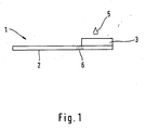
- FIG. 1 shows an example of the structure of a separating element (1).
- the separating element (1) contains a transport fleece (2) which, for. B. consists of glass fibers.
- a separating fleece (3) consisting of a filter medium is attached to the transport fleece (2).
- Transport and separation fleece differ essentially in terms of their different densities.
- B. a density of 77 g / cm 2 for a separating fleece and 53 g / cm 2 for a transport fleece (Whatman fleece).
- the lower density of the transport fleece enables the sample to be transported quickly along the fleece, while the higher density of the separating fleece ensures reliable separation of the plasma from blood.
- a drop of blood (5) is applied, the blood enters the separating fleece (3).
- the release unit therefore does not act on the transition zone of the transport fleece when the plasma is released, in order to avoid contamination of the rest of the plasma with the contaminants present here.
- the recess of the transition zone z. B. realized by a separation of the second area of the test element from the first area beyond this transition zone, so that the extraction of pure plasma is guaranteed.
- FIG 2 a) to c) shows an example of a method for plasma separation with an inventive Device (10).
- the device contains a hollow body (14), which has an outlet (13).
- the separating element is inside the hollow body (1) arranged in such a way that the separating fleece (3) protrudes from the hollow body (14) and is easily accessible to the user.
- the transport fleece (2) is inside of the hollow body (14).
- the device further includes a stamp (12) which is movably mounted within the device (14).
- the radius of the stamp (12) substantially equal to the inner radius of the hollow body (14), so that the Stamp (12) can be moved within the device by means of a button (11) can.
- Figure 2 b) shows a blood application (5) on a separating fleece (3) of a separating element (1).
- the plasma is passed along the separation fleece, while the remaining blood components are retained in the separation fleece. A complete plasma separation took place after approx. 2 to 10 seconds.
- the separated plasma is now passed on to the transport fleece (2).
- the button (11) is first the stamp (12) against the transport fleece (2) pressed so that this area of the separating element within the hollow body (14) is carried away by the stamp. Since the separating fleece (3) is positioned in the hollow body is, the transport fleece is separated from the separating fleece, one Separation takes place beyond the transition zone (6) shown in FIG. 1.
- the stamp (12) presses the plasma out of the Transport fleece (2) and releases them. Above the outlet (13) of the device plasma is then released (7).
- the plasma can, for. B. on a test element (17) can be applied to determine the HDL concentration.
- FIG. 3 shows different views of a further embodiment of the device (a - c).
- the device includes a rotatably mounted holder (21) in which a separating element (1) inside a channel (23) is positioned.
- the separating element (1) is in the holder positioned that the separating fleece (3) outside the holder and the device protrudes, so that - as it is shown in the side views - for the User for blood supply is easily accessible.
- the device also has a stamp (12) which is connected to the button (11). Furthermore, by means of the knob (11) a rotary element (22) are operated. First of all there is a blood test on the separating fleece (3) of the separating element (1), as in Figure 3 a) the side view is shown.
- the rotary element (22) is actuated.
- the holder (21) rotated approx. 90 °.
- the separating fleece (3) is separated from the transport fleece (2), the transition zone (6) of the transport fleece (2) remaining on the separating fleece (3).
- the stamp (12) that is initially located within the channel (23 a), transferred into the channel area (23 b).
- the transport fleece to be pressed against an outlet (13). located sieve (24).
- the sieve (24) preferably has a small thickness of 20 to 300 ⁇ m to avoid excessive dead volume. Via the outlet (13) the plasma is output.
Abstract
Description
Die Erfindung bezieht sich auf das Gebiet der Plasmagewinnung, die besonders bei analytischen Verfahren zur Bestimmung einer Konzentration von Blutbestandteilen eine Rolle spielt. Solche Bluttests können in vielen Fällen nicht mit Vollblut durchgeführt werden, da dieses korpuskuläre Bestandteile (Blutkörperchen) enthält, die bei der Ausführung des Verfahrens störende Einflüsse zur Folge hätten. Es ist deshalb notwendig, zur Durchführung vieler analytischer Verfahren zunächst das Plasma aus dem Vollblut zu gewinnen, das möglicht frei von zellulärem Material sein sollte.The invention relates to the field of plasma extraction, particularly at analytical method for determining a concentration of blood components matters. In many cases, such blood tests cannot be performed with whole blood because it contains corpuscular components (blood cells) that would have disruptive influences on the execution of the method. It is therefore necessary to carry out many analytical procedures, first the plasma from the To obtain whole blood, which should be free of cellular material if possible.
Ein gebräuchliches Verfahren zur Gewinnung von Plasma für Bluttests ist das Zentrifugationsverfahren, in dem aufgrund von Zentrifugalkräfte zelluläre Bestandteile des Blutes abgetrennt werden. Dieses Verfahren ist aufwendig und eignet sich insbesondere dann nicht, wenn nur geringe Mengen Plasma für eine Analyse benötigt werden. Besonders bei modernen miniaturisierten Tests zeigt sich jedoch, dass Plasmamengen nur im Bereich von einigen Mikrolitern verwendet werden. Dies gilt insbesondere für die sogenannten trägergebundenen Tests, bei denen ein möglichst kleines und kompaktes Analysesystem, beispielsweise in Form eines Teststreifens, vorliegt. Hierbei sind alle für die Durchführung des Tests notwendigen Reagenzien und sonstige Mittel in den Teststreifen integriert. Zur Bestimmung eines Analyten wird die Probenflüssigkeit in Kontakt mit einem derartigen Analyseelement gebracht. Das im Testelement enthaltene Reagenz reagiert innerhalb eines kurzen Zeitraumes mit dem zu bestimmenden Analyten, so dass an dem Analyseelement eine physikalisch nachweisbare Veränderung erfolgt. Eine derartige Veränderung kann beispielsweise eine Farbänderung oder eine Änderung einer elektrischen Messgröße sein. Mit Hilfe eines Auswertegerätes wird diese Veränderung vermessen und berechnet, so dass ein analytisches Resultat ausgegeben werden kann.A common method for obtaining plasma for blood tests is the centrifugation process, in which, due to centrifugal forces, cellular components of the Blood are separated. This process is complex and is particularly suitable not if only small amounts of plasma are needed for an analysis. However, especially with modern miniaturized tests it is shown that plasma quantities can only be used in the range of a few microliters. This applies in particular to the so-called carrier-bound tests, in which the smallest possible and most compact Analysis system, for example in the form of a test strip, is present. Here are all reagents and other means necessary for carrying out the test in the Integrated test strips. To determine an analyte, the sample liquid is in Brought into contact with such an analysis element. The one contained in the test element Reagent reacts with the analyte to be determined within a short period of time, so that a physically detectable change to the analysis element he follows. Such a change can be, for example, a color change or a Change of an electrical measured variable. With the help of an evaluation device, this is Measure and calculate change so that an analytical result is output can be.
Ein Beispiel für ein Analysesystem, das mittels eines derartigen Testelementes einen Analyten aus Plasma bestimmt, ist der HDL-Test (High Density Lipoproteins). Die Bestimmung der HDL-Konzentration im Blut ist unter anderem zur Risikoabschätzung einer koronaren Herzerkrankung von Bedeutung und dient damit zur Diagnose einer der häufigsten Erkrankungen in neuerer Zeit. An example of an analysis system that uses a test element of this type The analyte determined from plasma is the HDL test (High Density Lipoproteins). The Determination of the HDL concentration in the blood is, among other things, for risk assessment a coronary artery disease of importance and thus serves to diagnose one of the most common diseases in recent times.
Die Ausprägung einer koronaren Herzerkrankung ist anhand einiger bekannter Parameter, wie z. B. das Gesamtcholesterin, im Blut, Plasma oder Serum zu erkennen. Da die Konzentration des Gesamtcholesterins für die individuelle Risikoabschätzung nur bedingt geeignet ist, werden in modernen Analyseverfahren die Lipoproteine niedriger Dichte (Low Density Lipoproteins = LDL) sowie Lipoproteine hoher Dichte (HDL) separat voneinander quantifiziert. Bei der Auswertung der Analyseverfahren muss dabei berücksichtigt werden, dass zwischen dem LDL-Cholesterin und einer koronaren Herzerkrankung eine positive, jedoch zwischen dem HDL-Cholesterin und der Erkrankung eine negative Korrelation besteht. Klinische Studien haben bewiesen, dass in erster Nährung die Bestimmung sowohl des HDLs als auch des Gesamtcholesterins für eine Risikoabschätzung ausreichend ist. In der diagnostischen Praxis wird zur Zeit vorzugsweise dieser Weg beschritten.The manifestation of a coronary heart disease is based on some known parameters, such as B. to recognize the total cholesterol in the blood, plasma or serum. There the concentration of total cholesterol for individual risk assessment only is suitable to a limited extent, the lipoproteins become lower in modern analysis methods Density (Low Density Lipoproteins = LDL) and Lipoproteins high density (HDL) quantified separately. When evaluating the analysis methods, this must take into account that between the LDL cholesterol and a coronary Heart disease is a positive one, but between the HDL cholesterol and the disease there is a negative correlation. Clinical studies have proven that in the first Nutrition determines both HDL and total cholesterol for one Risk assessment is sufficient. In diagnostic practice it is currently preferred this path was followed.
Die Bestimmung des HDL-Cholesterins erfolgt beispielsweise mittels eines Analyseelements, wie es im Stand der Technik bekannt ist (z. B. HDL-Testelemente der Firma Roche Diagnostics GmbH). Da hierbei eine separate Bestimmung des HDL-Cholesterins erfolgt, müssen die anderen vorhandenen Lipoproteinklassen von den restlichen Blutbestandteilen abgetrennt werden, sodass die Bestimmung des HDL-Cholesterins aus Plasma erfolgt. Ein solcher Test benötigt beispielsweise ein Plasmavolumen von circa 40 µl, damit eine Konzentrationsbestimmung unabhängig vom aufgegebenen Plasmavolumen durchgeführt werden kann. Zur Bestimmung des HDL-Cholesterins kann dabei nur reines Plasma verwendet werden, in dem weitestgehend keine Blutbestandteile enthalten sind. Zur Bestimmung der HDL-Konzentration wird weiterhin ein Komplexbildner verwendet, der ebenfalls in dem Testelement integriert ist. Die Plasmaaufgabe erfolgt nun auf den Bereich des Testelementes, in dem der Komplexbildner vorhanden ist. Zur Analyse des HDL-Cholesterins wird z. B. im Stand der Technik der Komplexbildner EDTA eingesetzt. The HDL cholesterol is determined, for example, using an analysis element, as is known in the prior art (e.g. HDL test elements from the company Roche Diagnostics GmbH). Since this is a separate determination of HDL cholesterol the other existing lipoprotein classes must be different from the rest Blood components are separated so that the determination of HDL cholesterol done from plasma. Such a test requires, for example, a plasma volume of about 40 µl, so that a concentration determination regardless of the given Plasma volume can be carried out. For the determination of HDL cholesterol only pure plasma can be used in which there are largely no blood components are included. The determination of the HDL concentration continues a complexing agent is used, which is also integrated in the test element. The Plasma is now applied to the area of the test element in which the complexing agent is is available. For the analysis of HDL cholesterol z. B. in the state of Technology of complexing agents EDTA used.
Eine Bestimmung eines Analyten aus reinem Plasma kann jedoch auch mittels eines Testelementes erfolgen, bei dem kein Komplexbildner zur Bestimmung eines Analyten notwendig ist. Derartige Testelemente werden beispielsweise zur Enzymbestimmung verwendet und sind im Stand der Technik unter anderem im Dokument DE 3130749 beschrieben. Testelemente, die einen Analyten aus reinem Plasma bestimmen, jedoch keinen Komplexbildner enthalten, sind häufig so beschaffen, dass eine Plasmaseparation durch das Testelement selbst geleistet werden kann. Hierfür beinhalten derartige Testelemente zusätzlich zu einer Reagenzschicht eine Separationsschicht. Zur Vermessung eines Analyten wird zunächst Vollblut auf die Separationsschicht aufgegeben. Innerhalb der Separationsschicht werden Blutbestandteile von Plasma getrennt, wobei das Plasma zu der Reagenzschicht weitergeleitet wird. Die Bestimmung eines Analyten kann somit aus reinem Plasma erfolgen, obwohl Blut auf das Testelement aufgegeben wurde. Eine derartige im Testelement integrierte Plasmaseparationsschicht, kann hingegen bei der Verwendung von Komplexbildnern nicht eingesetzt werden. Muss ein Komplexbildner zur Bestimmung eines Analyten verwendet werden, zeigt sich, dass eine Separation des Plasmas von Blut durch den Komplexbildner im Testelement verhindert wird. Eine Plasmaseparation kann folglich dann nicht mehr durch das Testelement geleistet werden, wenn das Testelement einen Komplexbildner beinhaltet.However, an analyte can also be determined from pure plasma using a Test element take place in which no complexing agent for determining an analyte necessary is. Such test elements are used, for example, for enzyme determination used and are in the prior art, inter alia, in document DE 3130749 described. Test elements that determine an analyte from pure plasma, however contain no complexing agent, are often designed so that a plasma separation can be achieved by the test element itself. For this include such Test elements in addition to a reagent layer a separation layer. For measurement Whole blood is first applied to the separation layer. Blood components are separated from plasma within the separation layer, whereby the plasma is passed on to the reagent layer. The determination of an analyte can thus be made from pure plasma even though blood is applied to the test element has been. However, such a plasma separation layer integrated in the test element can not be used when using complexing agents. Has to be Complexing agents are used to determine an analyte, it turns out that a separation of the plasma from blood is prevented by the complexing agent in the test element becomes. A plasma separation can then no longer be carried out by the test element be performed if the test element contains a complexing agent.
Da zur Bestimmung des HDL-Cholesterins mittels eines oben beschriebenen Testelementes einerseits ein Komplexbildner notwendig ist, und andererseits eine Trennung des Plasmas vom Blut erforderlich ist, ergibt sich hieraus zwingend, dass eine Plasmaabtrennung vom Blut im µl-Maßstab bereits vor Blutaufgabe auf das Testelement geleistet werden muss.As for the determination of HDL cholesterol using a test element described above on the one hand a complexing agent is necessary, and on the other hand a separation of the plasma from the blood is necessary, it follows from this that a plasma separation of blood on a µl scale before the blood is applied to the test element must be done.
Die Bestimmung des HDL-Cholesterins ist hierbei nur ein wichtiges Beispiel für eine Analytbestimmung, die geringe Mengen reines Plasma zur Analyse benötigen. Weitere Anwendungsgebiete für die Verwendung von freigesetztem Plasma zeigen sich im Bereich der klinischen Analyse. Da derzeitig in der diagnostischen Praxis vorzugsweise Teststreifen als Analysesysteme verwendet werden, steigt das Bedürfnis, einfache Verfahren zur Gewinnung geringer Mengen an Plasma verwenden zu können, so dass insgesamt eine Vereinfachung sowie ein schneller Ablauf der Analyseverfahren resultiert.The determination of HDL cholesterol is only one important example of one Analyte determination, which require small amounts of pure plasma for analysis. Further Areas of application for the use of released plasma are shown in Area of clinical analysis. Because currently preferred in diagnostic practice Test strips are used as analysis systems, the need for simple procedures increases to be able to use small amounts of plasma, so that overall this results in a simplification as well as a quick flow of the analysis procedures.
Im Stand der Technik werden diesbezüglich mehrere Verfahren beschrieben, die die Gewinnung von geringen Mengen Plasma vereinfachen sollen. Dabei soll aus ebenfalls kleinen Blutvolumina das Plasma gewonnen werden, damit dem Patienten eine aufwendige Blutentnahme, wie sie z. B. für ein Zentrifugationsverfahren notwendig wäre, erspart bleibt.In this regard, several methods are described in the prior art, which the To simplify the extraction of small amounts of plasma. It should also from Small volumes of blood can be obtained from the plasma so that the patient has an elaborate process Blood sampling, such as B. would be necessary for a centrifugation process, is spared.
Seit vielen Jahren werden Filtrationsverfahren diskutiert und teilweise mit Erfolg verwendet, bei denen unterschiedliche Filtermedien, insbesondere Membran- und Glasfilter, zum Einsatz kommen. Frühere Beispiele für eine Filtrationstechnik sind in US-Patentschriften US 3,791,933 und US 4,477,575 beschrieben. Ein neueres Beispiel mit einer aufwendigen Kombination aus Membran- und Glasfiltern wird im Patent US 5,922,210 dargestellt. Mit Hilfe eines Mikrobauteils werden kleine Plasmamengen durch Mikrofiltration gewonnen. Die Abtrennung der Blutkörperchen erfolgt mit einem sogenannten Sperrkanal, der so klein ist, dass Blutkörpercheri nicht durch den Sperrkanal durchfließen können. Die Herstellung einer Vorrichtung mit einem derartigen Kanal erfordert jedoch spezielle Herstellungsverfahren, die aufwendig sind. Die genannten Plasmagewinnungsmethoden haben weiterhin den Nachteil, dass ein hohes Risiko besteht, die feinen Poren durch mechanischen Verschluss oder durch Addition von zellulärem Material an den Porenwänden zu verstopfen. Dadurch wird die Filterkapazität begrenzt. Eine Vergrößerung der Filterkapazität würde jedoch einen größeren Raumbedarf des Filtermediums bedingen. Dies würde wiederum die Relation zu dem aufgebrachten Probenvolumen und gewonnenen Plasmavolumen ungünstig beeinflussen.Filtration processes have been discussed for many years and some have been used successfully, where different filter media, especially membrane and glass filters, are used. Earlier examples of a filtration technique are in US Pat. Nos. 3,791,933 and 4,477,575. A recent example with an elaborate combination of membrane and glass filters is in the patent US 5,922,210. With the help of a micro component, small amounts of plasma obtained by microfiltration. The blood cells are separated with a so-called blocking channel, which is so small that blood corpuscles cannot pass through the Can flow blocking channel. The manufacture of a device with such Canal, however, requires special manufacturing processes that are complex. The The plasma extraction methods mentioned also have the disadvantage that a high There is a risk of the fine pores being closed mechanically or by addition of cellular material clogging the pore walls. This will reduce the filter capacity limited. However, increasing the filter capacity would make it larger Require space requirement of the filter medium. This in turn would relate to that adversely affect the sample volume applied and the plasma volume obtained.
Im Dokument US 4,477,575 wird ein Filterungsprozess zur Plasmagewinnung beschrieben mit einer Glasfaserschicht, durch den die Relation zwischen Probenvolumen und gewonnenen Plasmavolumen verbessert wird. Das Volumen des abzutrennenden Plasmas beträgt hierfür vorzugsweise weniger als 30 % vom Saugvolumen der Glasfaserschicht. Der Filterungsprozess erfolgt, nach dem Blut auf die Glasfaserschicht aufgegeben wurde und wird ausschließlich aufgrund von Schwerkraft angetrieben, sodass die Gewinnung des Plasmas entsprechend zeitaufwendig ist.A filtering process for plasma extraction is described in US Pat. No. 4,477,575 with a glass fiber layer, through which the relation between sample volume and obtained plasma volume is improved. The volume of the plasma to be separated is preferably less than 30% of the suction volume of the glass fiber layer. The filtering process takes place after the blood is applied to the glass fiber layer was and is driven solely by gravity, so the Obtaining the plasma is correspondingly time-consuming.
Um die Plasmagewinnung zu beschleunigen, werden im Stand der Technik weitere Möglichkeiten zur Plasmagewinnung beschrieben. In der Patentanmeldung EP 747105 wird zunächst in einem Gefäß ebenfalls eine Glasfaser gelagert, auf die das Blut aufgegeben wird. Mittels eines Stempels wird Druck auf die Glasfaser und das darin enthaltene Blut ausgeübt, sodass der Filterungsprozess beschleunigt wird. Das Blut wird somit durch die Glasfaser gepresst, wobei sich das Plasma von den restlichen Blutbestandteilen trennt. Das Plasma wird über einen Auslass ausgegeben. Nachteil der beschriebenen Vorrichtung ist jedoch, dass aufgrund des Filtervorganges größere Probenmengen Blut benötigt werden. Des Weiteren führt das Ausdrücken der Glasfaser zur Zerstörung der korpuskulären Blutbestandteile, sodass kein reines Plasma gewonnen werden kann.In order to accelerate the plasma generation, others are known in the art Possibilities for plasma generation described. In patent application EP 747105 First, a glass fiber is also stored in a vessel, onto which the blood is applied becomes. A stamp is used to apply pressure to the glass fiber and what it contains Blood is exerted so that the filtering process is accelerated. The blood becomes pressed through the glass fiber, separating the plasma from the remaining blood components separates. The plasma is discharged through an outlet. Disadvantage of the described However, the device is that due to the filtering process larger sample quantities Blood are needed. Furthermore, squeezing the glass fiber leads to destruction of the corpuscular blood components so that no pure plasma is obtained can.
Auf einem ähnlichen Prinzip basiert ein Gefäß zur Plasmagewinnung, das in der
Patentanmeldung EP 0 785 012 beschrieben wird. Hierbei wird ebenfalls Druck auf ein
Filtermaterial ausgeübt, auf dem zuvor Blut aufgegeben wurde, sodass eine Plasmaseparation
stattfindet. Wie bereits oben beschrieben, erfolgt auch hier aufgrund des
Auspressvorgangs eine Zerstörung der Blutkörperchen, sodass keine reine Plasmagewinnung
stattfindet. Wird das Plasma durch die Zerstörung der Blutkörperchen erst
einmal verunreinigt, ist es für die Verwendung einer Vielzahl von Analysetests nicht
geeignet.A vessel for plasma collection is based on a similar principle
Aufgabe der Erfindung ist es, eine Vorrichtung sowie ein Verfahren bereitzustellen, das zur Gewinnung von möglichst reinem Plasma im Mikroliter-Maßstab aus Vollblut geeignet ist. Dabei sollen die beschriebenen Nachteile des Standes der Technik überwunden werden.The object of the invention is to provide an apparatus and a method which to obtain the purest possible plasma on a microliter scale from whole blood suitable is. The disadvantages of the prior art described should be overcome become.
Die Erfindung beinhaltet eine Vorrichtung zur Separierung und Ausgabe von Plasma. Die Vorrichtung umfasst ein Trennelement, das einen ersten Bereich beinhaltet, auf dem eine Blutaufgabe erfolgt. Im ersten Bereich des Trennelementes werden korpuskuläre Blutbestandteile im wesentlichen vollständig zurückgehalten, während vorteilhafterweise durch Kapillarkräfte des Trennelementes Plasma in einen zweiten Bereich des Trennelementes geleitet wird. Das Trennelement ist dabei so in der Vorrichtung angeordnet, dass der erste Bereich des Trennelementes für den Benutzer zur Blutaufgabe zugänglich ist. Weiterhin beinhaltet die Vorrichtung eine Ausgabeeinheit, die nach der Plasmaseparierung auf den zweiten Bereich des Trennelementes wirkt, ohne dass auf den ersten Bereich des Trennelementes eine Einwirkung stattfindet, die z. B. zu einer Hämolyse des Blutes führen würde. Wirkt die Ausgabeeinheit ausschließlich auf den zweiten Bereich des Trennelementes, wird das separierte Plasma aus dem zweiten Bereich freigesetzt und über einen Auslass der Vorrichtung abgegeben. The invention includes a device for separating and dispensing plasma. The device comprises a separating element, which includes a first region who is given a blood test. In the first area of the separating element there are corpuscular ones Blood components essentially completely retained, while advantageously by capillary forces of the separating element plasma in a second area of the Separating element is directed. The separating element is arranged in the device that the first area of the separating element for the user to supply blood is accessible. Furthermore, the device includes an output unit, which according to the Plasma separation acts on the second area of the separating element without the first area of the separating element is exposed to a z. B. to one Hemolysis of the blood would result. Does the output unit only affect the second area of the separating element, the separated plasma from the second Area released and dispensed through an outlet of the device.
Weiterhin beinhaltet die Erfindung ein System zum Nachweis von Analyten im Blut. Das System beinhaltet neben der erfindungsgemäßen Vorrichtung - wie beschrieben - weiterhin ein Testelement, das bei Aufgabe des durch die Vorrichtung separierten Plasmas den Nachweis eines Analyten im Plasma ermöglicht.The invention further includes a system for the detection of analytes in the blood. In addition to the device according to the invention, the system includes - as described - Furthermore, a test element that separated by the device when abandoned Plasmas enables the detection of an analyte in the plasma.
Die erfindungsgemäße Vorrichtung gewährleistet eine effektive Plasmagewinnung im Mikroliter-Maßstab bereits schon aus geringem Probenvolumina. Beispielsweise können aus 100 µl Blut Plasmavolumina von 30 µl oder mehr gewonnen werden. Die erfindungsgemäße Vorrichtung ist damit besonders geeignet im Bereich der modernen Analyse eingesetzt zu werden, da bereits bei der Entnahme von geringen Probenvolumina eine schnelle Plasmaseparation, sowie die Ausgabe des Plasmas vorteilhafterweise auf einen Teststreifen ermöglicht wird. Beträgt das aufgegebene Blutvolumen vorzugsweise 30 bis 150 µl, kann mittels der erfindungsgemäßen Vorrichtung hinreichend Plasmamengen gewonnen werden, die für handelsübliche Testelemente vorgeschrieben sind, damit eine Analytkonzentration unabhängig vom aufgegebenen Probenvolumen bestimmt werden kann. Mittels der erfindungsgemäßen Vorrichtung ist es folglich möglich, trotz geringer Blutvolumina hinreichend große Plasmamengen zu gewinnen, um den Anforderungen handelsüblicher Analyseverfahren insbesondere mit Testelementen zu genügen.The device according to the invention ensures effective plasma extraction in the Microliter scale already from small sample volumes. For example plasma volumes of 30 µl or more can be obtained from 100 µl blood. The The device according to the invention is therefore particularly suitable in the field of modern Analysis to be used because even with the removal of small sample volumes a rapid plasma separation, as well as the output of the plasma advantageously on a test strip. The volume of blood given is preferably 30 to 150 ul, can be sufficient by means of the device according to the invention Plasma quantities are obtained, which are prescribed for commercially available test elements so that an analyte concentration is independent of the sample volume can be determined. It is consequently by means of the device according to the invention possible to obtain sufficiently large amounts of plasma despite low blood volumes, the requirements of commercial analysis methods, especially with test elements to suffice.
Die erfindungsgemäße Vorrichtung erlaubt weiterhin eine besonders einfache und kostengünstige Herstellung des Systems, da z. B. keine Mikrostrukturen (Mikrokanäle) beim Herstellungsprozess in die Vorrichtung integriert werden müssen. Die Separation des Plasmas erfolgt mittels eines Trennelementes, das vorteilhafterweise zur einmaligen Verwendung ausgelegt ist. Eine Verstopfungen der mikroporöser Strukturen bei mehrmaliger Verwendung sowie Verunreinigungen können somit vermieden werden.The device according to the invention also allows a particularly simple and cost-effective production of the system because z. B. no microstructures (microchannels) must be integrated into the device during the manufacturing process. The separation of the plasma takes place by means of a separating element, which is advantageously unique Use is designed. A blockage of the microporous structures with repeated Use and contamination can thus be avoided.
Weitere wesentliche Vorteile der Erfindung ergeben sich durch die Freisetzung des Plasmas und das Abtrennen des Plasmas aus Blut, die im Sinne der Erfindung als zwei separate, hintereinanderfolgende Vorgänge durchgeführt werden. Somit ist es möglich, die Plasmagewinnung zu beschleunigen, ohne dass hierbei, wie im Stand der Technik üblich, Druck während des Separationsvorgangs auf die Probe ausgeübt wird. Erfindungsgemäß wird im wesentlichen nur durch Einwirkung auf den zweiten Bereich des Trennelementes das Plasma freigesetzt, wobei dieser Vorgang beliebig z. B. durch Überdruck, Unterdruck oder Eluierungsprozesse etc. beschleunigt werden kann. Von diesem Vorgang im wesentlichen unberücksichtigt bleibt der Schritt der Plasmaseparation, der unabhängig von dem Freisetzungsprozess durchgeführt wird und z. B. durch Kapillarkräfte, die innerhalb des ersten Bereiches des Trennelementes wirken, ebenfalls beschleunigt werden kann. Hierbei sollte jedoch darauf geachtet werden, dass eine Beschleunigung der Plasmaseparation nur so weit erfolgt, dass weiterhin eine zuverlässige Separation des Plasmas von den restlichen Blutbestandteilen sicher gewährleistet ist. Insbesondere sind hierbei Vorgänge, die z. B. Scherkräfte bedingen zu vermeiden, die eine Hämolyse während der Plasmaseparation bewirken würden. Die Erfindung ermöglicht folglich ein beschleunigtes Verfahren der Plasmaseparation, ohne das eine Kontamination des Plasmas mit restlichen Blutbestandteilen in Kauf genommen werden muss.Further essential advantages of the invention result from the release of the plasma and the separation of the plasma from blood, which in the sense of the invention are two separate, successive operations are performed. It is therefore possible to Accelerate plasma generation without doing so, as in the prior art usual, pressure is applied to the sample during the separation process. According to the invention is essentially only by acting on the second area of the Separating element released the plasma, this process arbitrarily z. B. by Overpressure, underpressure or elution processes etc. can be accelerated. Of this step is largely ignored Plasma separation, which is carried out regardless of the release process and z. B. by capillary forces within the first region of the separating element act, can also be accelerated. However, care should be taken here that the plasma separation only accelerates to the extent that reliable separation of the plasma from the remaining blood components is guaranteed. In particular, here are processes that, for. B. shear forces to avoid conditions that cause hemolysis during plasma separation would. The invention consequently enables an accelerated process of Plasma separation without contamination of the plasma with the rest Blood components must be accepted.
Im Bereich der modernen Analyse ist die Erfindung insbesondere zur Aufgabe von reinem Plasma auf Testelemente geeignet, die - wie beschrieben - einen Komplexbildner enthalten und aufgrund des Komplexbildners eine Plasmaseparation innerhalb des Testelementes selbst nicht verwirklicht werden kann.In the field of modern analysis, the invention is in particular the object of pure plasma on test elements suitable, which - as described - a complexing agent contain and due to the complexing agent a plasma separation within of the test element itself cannot be realized.
Es ist jedoch auch eine Anwendungsmöglichkeit für Testelemente denkbar, die keinen Komplexbildner enthalten. Obwohl das Plasma hier handelsüblich auch mittels einer Separationsschicht im Testelement selbst abgetrennt werden kann und der Benutzer folglich bei dem Gebrauch dieser Testelemente nicht auf eine gesonderte Plasmaabtrennung angewiesen ist, erlaubt das erfindungsgemäße System z.B. hier einen vereinfachten Aufbau der Testelemente. Die Testelemente müssen somit nur noch über eine Reagenzschicht und nicht mehr über eine Separationsschicht bzw. Trennvlies verfügen. Hierdurch ergibt sich u. a. eine Reduktion der Produktionsschritte, die zur Kostenreduktion der Testelemente führen.However, it is also conceivable to use test elements that do not Contain complexing agents. Although the plasma is also commercially available here using a Separation layer in the test element itself can be separated and the user consequently when using these test elements not on a separate plasma separation the system according to the invention allows e.g. here a simplified one Structure of the test elements. The test elements therefore only have to be placed over a reagent layer and no longer have a separation layer or separation fleece. This results in u. a. a reduction in the production steps leading to cost reduction of the test elements.
In Anlehnung an die im Stand der Technik beschriebenen Testelemente mit einer Separationsschicht bzw. Trennvlies ist eine bevorzugte Ausführungsform eines erfindungsgemäßen Trennelementes in einer ersten Nährung nach einem analogen Prinzip aufgebaut. Zur näheren Beschreibung handelsüblicher Testelemente mit Separationsschicht wird z. B. auf das Dokument DE 3130749 verwiesen. Das Dokument beschreibt ein Testelement, bei dem zunächst das Plasma vom Blut abgetrennt wird, sodass ausschließlich Plasma zu einer Reagenzschicht weitergeleitet wird. Mit Hilfe des Reagenzes erfolgt nun eine Bestimmung eines Analyten in Plasma. Zu diesem Zweck hat das Testelement eine auf dem Basisstreifen angeordnete, flache Separationsschicht, auf die an einem Ende die Blutprobe aufgegeben wird. Die Separationsschicht besteht aus Glasfasermaterial, das Blutkörperchen in der Nähe der Aufgabenstelle zurückhält. Das Blutplasma breitet sich dagegen in der Schicht aus, sodass sich in dem von der Aufgabenstelle entfernten Bereich der Separationsschicht ein "Plasmasee" zur Verfügung steht. Üblicherweise befindet sich eine Reagenzschicht ober- oder unterhalb des Plasmasees, durch die anschließend eine Analytbestimmung im Plasma erfolgen kann. Zur Auswertung eines derartigen Testträgers werden entsprechende Auswertegeräte, wie sie im Stand der Technik bekannt sind, verwendet.Based on the test elements described in the prior art with a separation layer or separation fleece is a preferred embodiment of an inventive Separating element built in a first approximation according to an analog principle. For a more detailed description of commercially available test elements with a separation layer z. B. referred to the document DE 3130749. The document describes a Test element in which the plasma is first separated from the blood, so that exclusively Plasma is passed to a reagent layer. With the help of the reagent an analyte is now determined in plasma. For this purpose the test element a flat separation layer arranged on the base strip, onto which the blood sample is given to one end. The separation layer consists of glass fiber material, restrains the blood cells near the task site. The blood plasma on the other hand spreads in the shift, so that in the of the task position distant area of the separation layer a "plasma lake" is available. Usually there is a reagent layer above or below the plasma lake, which can then be used to determine the analyte in the plasma. To the results Such a test carrier are appropriate evaluation devices, as in State of the art are used.
Nachteil dieser Analysesysteme ist jedoch, dass die Anwendung des so gewonnenen "Plasmasees" auf das beschriebene System beschränkt ist. Eine Analyse des im Plasma enthaltenen Analyten ist somit nur im Rahmen des Testträgersystems möglich, da ein Freisetzen des Plasmas aus dem Testträger nicht möglich ist.The disadvantage of these analysis systems is, however, that the application of the thus obtained "Plasma lakes" is limited to the system described. An analysis of the plasma contained analytes is therefore only possible within the framework of the test carrier system, since a It is not possible to release the plasma from the test carrier.
Enthält eine erfindungsgemäße Vorrichtung ein Trennelement, das den Aufbau eines
derartigen Testelementes vereinfacht wiedergibt, beinhaltet ein solches Trennelement
beispielsweise in seinem ersten Bereich eine Separationsschicht, die im Folgenden auch
als Trennvlies bezeichnet wird sowie in einem zweiten Bereich ein Transportvlies, in
dem sich das Plasma in einem entfernten Bereich von der Separationsschicht sammelt.
Eine bevorzugte Ausführungsform des Trennelementes hat folglich einen testträgeranalogen,
streifenförmigen Aufbau, ohne dass eine Reagenzschicht vorhanden ist. Das
Trennelement beinhaltet vorzugsweise in seinem Trennvlies einen Filter, der z. B. aus
Glasfasermaterial besteht, sodass eine im wesentlichen vollständige Separation des
Plasmas vom Blut gewährleistet wird. Weitere handelsübliche Vliese sind z. B. in dem
Dokument EP 0 045 476 beschrieben oder im Handel unter dem Namen Whatman-Vlies
erhältlich. Der Filterungsprozess wird hierbei erfindungsgemäß im wesentlichen
nicht durch Druck unterstützt, sodass eine Zerstörung der Blutkörperchen im ersten
Bereich des Trennelementes vermieden wird. Wirkt dennoch zur Unterstützung des
Filterungsprozesses z. B. ein Unterdruck auf den ersten Bereich des Trennelementes, so
ist darauf zu achten, dass ein Druck nur in dem Maße ausgeübt wird, dass hierdurch
keine Hämolyse bewirkt wird.A device according to the invention contains a separating element that has the structure of a
reproduces such test element in a simplified manner includes such a separating element
For example, in its first area, a separation layer, which also below
is referred to as a separating fleece and, in a second area, a transport fleece, in
which the plasma collects in a distant area from the separation layer.
A preferred embodiment of the separating element consequently has a test carrier analog,
strip-like structure without a reagent layer. The
Separating element preferably includes a filter in its separating fleece, which, for. B. from
Glass fiber material exists, so that an essentially complete separation of the
Plasma is guaranteed by blood. Other commercially available nonwovens are e.g. B. in the
Das Freisetzen des Plasmas erfolgt nun anschließend durch Einwirkung auf den zweiten Bereich des Trennelementes, ohne dass der erste Bereich des Trennelements beeinflusst wird. Eine Verunreinigung des Plasmas durch den Verfahrensschritt der Plasmafreisetzung wird somit erfindungsgemäß verhindert.The plasma is then released by acting on the second one Area of the separating element without influencing the first area of the separating element becomes. Contamination of the plasma by the plasma release process step is thus prevented according to the invention.
Vorzugsweise wird zur Freisetzung des Plasmas Druck auf den zweiten Bereich des Trennelementes ausgeübt, sodass das Plasma aus dem zweiten Bereich des Trennelementes ausgepresst wird. Wird Plasma aus dem Trennelement ausgepresst, ist hierbei zu beachten, dass ausschließlich auf den zweiten Bereich des Trennelementes Druck ausgeübt wird, in dem keine Blutbestandteile mehr enthalten sind, sodass eine Hämolyse vermieden wird. Prinzipiell sind vielfältige Möglichkeiten zur Freisetzung des Plasmas denkbar, wobei der Verfahrensschritt der Plasmafreisetzung erfindungsgemäß unabhängig von der Plasmaseparation stattfindet, sodass sich aus dem Verfahrensschritt der Plasmaseparation keine Einschränkungen für die Plasmafreisetzung ergeben. Ein weiteres Beispiel für die Plasmafreisetzung ist das Eluieren des separierten Plasmas. Über einen Auslass der Vorrichtung wird anschließend das freigesetzte Plasma dosiert abgegeben.Preferably, to release the plasma, pressure is applied to the second region of the Separating element exerted so that the plasma from the second region of the separating element is squeezed. If plasma is pressed out of the separating element, here is note that pressure is only on the second area of the separating element is exercised in which there are no longer any blood components, so that Hemolysis is avoided. In principle, there are many ways to release the Plasma is conceivable, the process step of plasma release according to the invention takes place independently of the plasma separation, so that from the Process step of plasma separation no restrictions for the Plasma release results. Another example of plasma release is that Elute the separated plasma. Via an outlet of the device then the released plasma is dispensed in doses.
Für die Freisetzung des Plasmas erweist es sich weiterhin als vorteilhaft, wenn die Kräfte zur Freisetzung des Plasmas im wesentlichen senkrecht zur Ebene, in der sich das Trennelement befindet, auf den zweiten Bereich des Trennelementes wirken. Auf diese Weise kann gewährleistet werden, dass keine Beeinflussung des ersten Bereiches des Trennelementes erfolgt, die eine Kontamination des freizusetzenden Plasmas mit den restlichen Blutbestandteilen bedingen würde.For the release of the plasma, it also proves to be advantageous if the forces to release the plasma essentially perpendicular to the plane in which the Separating element is located, act on the second region of the separating element. To this In this way it can be ensured that the first region of the Separating element takes place, which contaminates the plasma to be released with the remaining blood components.
Hierbei ist z. B. eine Ausführungsform mit einem Stempel denkbar, bei der der Stempel innerhalb der Vorrichtung ober- oder unterhalb der Ebene, in der der zweite Bereich des Trennelementes positioniert ist, angeordnet ist. Durch ein Andrücken des Stempels gegen das Trennelement, wird somit ausschließlich Druck auf den zweiten Bereich des Trennelementes ausgeübt und das Plasma freigegeben.Here is z. B. an embodiment with a stamp conceivable in which the stamp inside the device above or below the level in which the second area the separating element is positioned, is arranged. By pressing the stamp against the separating element, thus only pressure on the second area of the Separating element exercised and the plasma released.
Es ist weiterhin auch denkbar, dass zur sicheren Freisetzung von reinem Plasma zunächst der zweite Bereich des Trennelementes vom ersten Bereich des Trennelementes abgetrennt wird, so dass z. B. eine räumliche Trennung der Trennelementbereiche stattfinden kann. Hierbei wird vorteilhafterweise darauf geachtet, dass die Abtrennung des zweiten Bereiches vom ersten Bereich erst an einer Stelle des Trennelementes erfolgt, in dem im wesentlichen nur noch Plasma vorhanden ist, sodass keine korpuskulären Blutbestandteile im zweiten Bereich des Trennelementes das Plasma verunreinigen. Eine Freisetzung des Plasmas kann nun aufgrund der räumlichen Trennung auf vielfältige Weise durchgeführt werden, ohne dass eine Beeinträchtigung auf den ersten Bereich befürchtet werden muss.It is also conceivable that safe release of pure plasma first the second area of the separating element from the first area of the separating element is separated so that, for. B. a spatial separation of the separator areas can take place. It is advantageously ensured that the The second area is only separated from the first area at one point of the separating element takes place in which essentially only plasma is present, so that none corpuscular blood components in the second area of the separating element the plasma contaminate. A release of the plasma can now occur due to the spatial separation can be done in a variety of ways without affecting the first area must be feared.
Eine Abtrennung des zweiten Bereichs des Trennelementes von dem ersten Bereich kann z. B. durch eine Halterung verwirklicht werden, die mit dem zweiten Bereich des Trennelementes verbunden ist. Wird durch den Benutzer eine Kraft (Ziehen, Drücken, Drehen etc.) auf diese Halterung ausgeübt, wird diese Kraft direkt oder indirekt auf den zweiten Bereich des Trennelementes übertragen und führt hierdurch zur Abtrennung des zweiten Bereichs. Hierbei ist es z. B. möglich, dass durch eine Drehung der Halterung um vorzugsweise 90° ein Abtrennen des zweiten Bereiches vom ersten Bereich, der ortsfest innerhalb der Vorrichtung fixiert ist, bewirkt wird.A separation of the second area of the separating element from the first area can e.g. B. be realized by a bracket that with the second area of Separating element is connected. If the user exerts a force (pulling, pushing, Turning etc.) exerted on this bracket, this force is directly or indirectly on the transferred second region of the separating element and thereby leads to the separation of the second area. Here it is e.g. B. possible that by rotating the bracket by preferably 90 ° separating the second area from the first area, the is fixed within the device, is effected.
In einer weiteren vorteilhaften Ausführungsform erfolgt das Abtrennen des Trennelementes sowie das anschließende Freisetzen des Plasmas aus dem zweiten Bereich in zwei hintereinanderfolgenden Schritte, die durch Betätigung ein und derselbe Auslöseeinheit an der Vorrichtung erfolgt. Eine derartige Auslöseeinheit ist dann mit der Halterung der Vorrichtung in der Weise verbunden, dass bei einer ersten Betätigung der Auslöseeinheit zunächst eine Durchtrennung des Elementes bewirkt wird und eine weitere Betätigung der Auslöseeinheit zur Plasmafreisetzung führt. Auslöseeinheiten, wie beschrieben, sind vorteilhafterweise in Form eines Auslöseknopfes verwirklicht, der in einem ersten Schritt z. B. zunächst ein Drehen einer Halterung bewirkt, die mit dem zweiten Bereich des Trennelementes verbunden ist, sodass eine Drehung dieses Trennelementbereiches resultiert. Während der Drehbewegung des in der Halterung befestigten zweiten Bereiches verbleibt der erste Teil des Trennelementes ortsfest in der Vorrichtung. Die durch die Drehbewegung wirkenden Kräfte führen zur Teilung des Trennelementes. Hierbei ist es z. B. denkbar, dass ein Schneideelement in der Vorrichtung so positioniert ist, dass der zweite Bereich des Trennelementes während der Drehbewegung gegen das Schneideelement gedrückt wird. Eine Teilung des Trennelementes wird somit erleichtert und kann präzise durchgeführt werden. Wird auf ein Schneideelement verzichtet, kann ein Durchtrennen des Trennelementes ebenfalls durch ein Abreißen des ersten Bereiches vom zweiten Bereich bewirkt werden. Anschließend wird das Plasma mittels der Ausgabeeinheit freigesetzt. In a further advantageous embodiment, the separating element is separated and the subsequent release of the plasma from the second area in two successive steps, by actuating one and the same release unit done on the device. Such a trigger unit is then with the bracket connected to the device in such a way that when the Tripping unit is first cut through and a further actuation of the trigger unit leads to plasma release. Trip units as described, are advantageously realized in the form of a release button that in a first step z. B. first causes rotation of a bracket with the second area of the separating element is connected, so that a rotation of this separating element area results. During the rotation of the attached in the holder second area, the first part of the separating element remains stationary in the device. The forces caused by the rotary movement lead to the division of the Separating element. Here it is e.g. B. conceivable that a cutting element in the device is positioned so that the second area of the separating element during the rotary movement is pressed against the cutting element. A division of the separating element is thus facilitated and can be carried out precisely. Will be on a cutting element waived, cutting the separating element can also by Tear off the first area from the second area. Then will the plasma is released by means of the output unit.
Ist in einer vorteilhaften Ausführungsform der Vorrichtung das Trennelement als Einmalartikel ausgelegt, sodass eine irreversible Durchtrennung des Elementes nicht nachteilig ist, ist es weiterhin denkbar, die Halterung ebenfalls als fest mit dem Trennelement verbundenen Einmalartikel anzubieten. Für den Benutzer würde somit das Handling der Vorrichtung beim Wiedereinlegen eines neuen Trennelementes stark vereinfacht, da insbesondere bei älteren Personen eine Handhabung kleiner Gerätebauteile Schwierigkeiten hervorruft. Zur weiteren Vereinfachung der Handhabungsschritte bietet sich darüber hinaus eine Magazinierung der Halterung mit Trennelement in einem Spender an, der eine Ausgabe des Einmalartikels stückweise zulässt.In an advantageous embodiment of the device, the separating element is as Disposable items designed so that an irreversible severing of the element is not is disadvantageous, it is also conceivable for the holder to also be fixed to the separating element offer related one-off items. For the user, that would be Handling of the device when reinserting a new separating element is greatly simplified, handling of small device components, especially in the case of older people Creates difficulties. To further simplify the handling steps In addition, a magazine of the holder with separating element in to a donor who allows the disposable item to be issued piece by piece.
Weiterhin ist Gegenstand der Erfindung ein Verfahren zur Plasmaseparierung und der Ausgabe. Das Verfahren beinhaltet die Aufgabe von Blut auf einen ersten Bereich eines Trennelementes, welches einen ersten und einen zweiten Bereich beinhaltet. Mittels des Trennelementes wird das Plasma von anderen Blutbestandteilen separiert, wobei das Plasma in den zweiten Bereich des Trennelementes weitergeleitet wird und die verbleibenden Blutbestandteile im wesentlichen im ersten Bereich des Trennelementes zurückgehalten werden. Anschließend wird der zweite Bereich des Trennelementes in der Weise bearbeitet, dass das Plasma aus dem zweiten Bereich des Trennelementes freigesetzt wird. Hierbei ist darauf zu achten, dass keine Bearbeitung des ersten Bereiches des Trennelementes erfolgt, die beispielsweise durch eine Hämolyse eine Kontamination des Plasmas mit den zuvor abgetrennten Blutbestandteilen verursachen würde. Über einen Auslass der Vorrichtung erfolgt eine Ausgabe des freigesetzten Plasmas.The invention furthermore relates to a method for plasma separation and Output. The method involves applying blood to a first area of a Separating element, which includes a first and a second region. By means of the Separating element, the plasma is separated from other blood components, the Plasma is forwarded to the second area of the separating element and the remaining Blood components essentially in the first area of the separating element be held back. The second area of the separating element is then in processed in such a way that the plasma from the second region of the separating element is released. It is important to ensure that the first area is not processed of the separating element, which is contaminated, for example, by hemolysis of the plasma with the previously separated blood components would. The released plasma is output via an outlet of the device.
Vorteilhafte Ausführungsform des Verfahrens ergeben sich wie beschrieben. Vorzugsweise erfolgt das Verfahren zur Plasmaabtrennung und Freisetzung mittels einer Vorrichtung wie beschrieben.Advantageous embodiments of the method result as described. Preferably the process for plasma separation and release takes place by means of a device as described.
Die erfindungsgemäße Vorrichtung sowie das erfindungsgemäße Verfahrens erlauben folglich eine einfach und schnell durchführbare Separierung von Plasma aus Blut im Mikroliter-Maßstab. Die Vorrichtung ist hierbei bequem zu handhaben und erlaubt eine preiswerte Herstellung. Beispielhaft werden nachfolgend einige vorteilhafte Ausführungsformen in den Figuren dargestellt und beschrieben.
- Figur 1:
- Aufbau eines Trennelementes
- Figur 2:
- Vorrichtung zur Separierung von Plasma
- Figur 3:
- Vorrichtung zur Separierung von Plasma mit einer drehbar gelagerten Halterung
- Figure 1:
- Structure of a separating element
- Figure 2:
- Device for separating plasma
- Figure 3:
- Device for separating plasma with a rotatably mounted holder
Figur 1 zeigt beispielhaft den Aufbau eines Trennelementes (1). Das Trennelement ( 1 ) enthält ein Transportvlies (2), das z. B. aus Glasfasern besteht. Auf dem Transportvlies (2) ist ein Trennvlies (3) angebracht, das aus einem Filtermedium besteht. Transport- und Trennvlies unterscheiden sich im wesentlichen anhand unterschiedlicher Dichte. Hierbei sind im Stand der Technik z. B. eine Dichte von 77 g/cm2 für ein Trennvlies und 53 g/cm2 für ein Transportvlies (Whatman-Vlies) angegeben. Die geringere Dichte des Transportvlieses ermöglicht einen schnellen Transport der Probe entlang des Vlieses, während die höhere Dichte des Trennvlieses eine sichere Separation des Plasmas von Blut gewährleistet. Bei Aufgabe eines Bluttropfens (5) gelangt das Blut in das Trennvlies (3). Aufgrund des Filtermediums im Trennvlies werden die Blutbestandteile vom Plasma getrennt und im Trennvlies (3) zurückgehalten. Das Plasma wird mittels Kapillarkräfte, die innerhalb des Transportvlieses wirken, weitergeleitet. Hierbei zeigt sich häufig, dass Blutbestandteile in geringer Konzentration durch Kapillarkräfte aus dem Trennvlies (3) in einen kleinen Bereich des Transportvlieses (2) gelangen können. Dieser Bereich wird als Übergangszone (6) bezeichnet und enthält kein reines Plasma. In einer vorteilhaften Ausführungsform der erfindungsgemäßen Vorrichtung wirkt deshalb bei der Freisetzung des Plasmas die Ausgabeeinheit nicht auf die Übergangszone des Transportvlieses, um eine Kontamination des übrigen Plasmas mit den hier vorhandenen Verunreinigungen zu vermeiden. Wie in Figur 2 gezeigt, wird das Aussparen der Übergangszone z. B. durch eine Abtrennung des zweiten Bereiches des Testelementes vom ersten Bereich jenseits dieser Übergangszone verwirklicht, sodass die Gewinnung von reinem Plasma gewährleistet ist.Figure 1 shows an example of the structure of a separating element (1). The separating element (1) contains a transport fleece (2) which, for. B. consists of glass fibers. A separating fleece (3) consisting of a filter medium is attached to the transport fleece (2). Transport and separation fleece differ essentially in terms of their different densities. Here are in the prior art such. B. a density of 77 g / cm 2 for a separating fleece and 53 g / cm 2 for a transport fleece (Whatman fleece). The lower density of the transport fleece enables the sample to be transported quickly along the fleece, while the higher density of the separating fleece ensures reliable separation of the plasma from blood. When a drop of blood (5) is applied, the blood enters the separating fleece (3). Due to the filter medium in the separation fleece, the blood components are separated from the plasma and retained in the separation fleece (3). The plasma is passed on by means of capillary forces that act within the transport fleece. This often shows that blood components in a low concentration can get from the separating fleece (3) into a small area of the transport fleece (2) due to capillary forces. This area is called the transition zone (6) and contains no pure plasma. In an advantageous embodiment of the device according to the invention, the release unit therefore does not act on the transition zone of the transport fleece when the plasma is released, in order to avoid contamination of the rest of the plasma with the contaminants present here. As shown in Figure 2, the recess of the transition zone z. B. realized by a separation of the second area of the test element from the first area beyond this transition zone, so that the extraction of pure plasma is guaranteed.
Figur 2 a) bis c) zeigt beispielhaft ein Verfahren zur Plasmaseparierung mit einer erfindungsgemäßen Vorrichtung (10). Die Vorrichtung beinhaltet einen Hohlkörper (14), der über einen Auslass (13) verfügt. Innerhalb des Hohlkörpers ist das Trennelement (1) in der Weise angeordnet, dass das Trennvlies (3) aus dem Hohlkörper (14) ragt und für den Benutzer leicht zugänglich ist. Das Transportvlies (2) befindet sich innerhalb des Hohlkörpers (14). Die Vorrichtung beinhaltet weiterhin einen Stempel (12), der beweglich innerhalb der Vorrichtung (14) gelagert ist. Dabei ist der Radius des Stempels (12) im wesentlichen gleich dem inneren Radius des Hohlkörpers (14), sodass der Stempel (12) mittels eines Knopfes (11) innerhalb der Vorrichtung bewegt werden kann. Figur 2 b) zeigt eine Blutaufgabe (5) auf ein Trennvlies (3) eines Trennelementes (1). Gelangt das Blut in das Trennvlies, wird das Plasma entlang des Trennvlieses weitergeleitet, während die restlichen Blutbestandteile im Trennvlies zurückgehalten werden. Nach ca. 2 bis 10 Sekunden hat eine vollständige Plasmaseparierung stattgefunden. Das separierte Plasma wird nun in das Transportvlies (2) weitergeleitet. Durch Betätigung des Knopfes (11) wird zunächst der Stempel (12) gegen das Transportvlies (2) gedrückt, so dass dieser Bereich des Trennelementes innerhalb des Hohlkörpers (14) vom Stempel mitgerissen wird. Da das Trennvlies (3) im Hohlkörper ortsfest positioniert ist, kommt es zur Abtrennung des Transportvlieses vom Trennvlies, wobei eine Trennung jenseits der in Figur 1 dargestellten Übergangszone (6) erfolgt. Durch weitere Betätigung des Knopfes (11) wird das abgetrennte Transportvlies (2) gegen die Wand (16) des Gehäuses (14) gedrückt. Der Stempel (12) presst dabei das Plasma aus dem Transportvlies (2) aus und gibt diese frei. Über dem Auslass (13) der Vorrichtung erfolgt anschließend eine Plasmaabgabe (7). Das Plasma kann so z. B. auf ein Testelement (17) zur Bestimmung der HDL-Konzentration aufgetragen werden.Figure 2 a) to c) shows an example of a method for plasma separation with an inventive Device (10). The device contains a hollow body (14), which has an outlet (13). The separating element is inside the hollow body (1) arranged in such a way that the separating fleece (3) protrudes from the hollow body (14) and is easily accessible to the user. The transport fleece (2) is inside of the hollow body (14). The device further includes a stamp (12) which is movably mounted within the device (14). Here is the radius of the stamp (12) substantially equal to the inner radius of the hollow body (14), so that the Stamp (12) can be moved within the device by means of a button (11) can. Figure 2 b) shows a blood application (5) on a separating fleece (3) of a separating element (1). If the blood gets into the separation fleece, the plasma is passed along the separation fleece, while the remaining blood components are retained in the separation fleece. A complete plasma separation took place after approx. 2 to 10 seconds. The separated plasma is now passed on to the transport fleece (2). By actuation the button (11) is first the stamp (12) against the transport fleece (2) pressed so that this area of the separating element within the hollow body (14) is carried away by the stamp. Since the separating fleece (3) is positioned in the hollow body is, the transport fleece is separated from the separating fleece, one Separation takes place beyond the transition zone (6) shown in FIG. 1. By more Pressing the button (11) the separated transport fleece (2) against the wall (16) of the housing (14) pressed. The stamp (12) presses the plasma out of the Transport fleece (2) and releases them. Above the outlet (13) of the device plasma is then released (7). The plasma can, for. B. on a test element (17) can be applied to determine the HDL concentration.
Figur 3 zeigt verschiedene Ansichten von einer weiteren Ausführungsart der Vorrichtung (a - c). Die Vorrichtung beinhaltet zusätzlich zu der in Figur 2 gezeigten Ausführungsform eine drehbar gelagerte Halterung (21), in der ein Trennelement ( 1 ) innerhalb eines Kanales (23) positioniert ist. Das Trennelement (1) ist dabei so in der Halterung positioniert, dass das Trennvlies (3) außerhalb der Halterung sowie der Vorrichtung ragt, so dass es - wie es in den Seitenansichten jeweils verdeutlicht wird - für den Benutzer zur Blutaufgabe leicht zugänglich ist. Die Vorrichtung verfügt weiterhin über einen Stempel (12), der mit dem Knopf (11) in Verbindung steht. Weiterhin kann mittels des Knopfes (11) ein Drehelement (22) betätigt werden. Zunächst erfolgt eine Blutaufgabe auf das Trennvlies (3) des Trennelementes (1), wie es in Figur 3 a) der Seitenansicht dargestellt ist. Nachdem die Separation des Plasmas vom Blut erfolgt ist, wird durch ein erstes Drücken des Knopfes (11) das Drehelement (22) betätigt. Durch eine nach unten gerichtete Bewegung des Drehelementes (22) wird die Halterung (21) um ca. 90° gedreht. Hierbei wird das Trennvlies (3) vom Transportvlies (2) abgetrennt, wobei die Übergangszone (6) des Transportvlieses (2) am Trennvlies (3) verbleibt. Durch weiteres Betätigen des Knopfes (11) wird nun der Stempel (12), der sich zunächst innerhalb des Kanales (23 a) befindet, in den Kanalbereich (23 b) überführt. FIG. 3 shows different views of a further embodiment of the device (a - c). In addition to the embodiment shown in FIG. 2, the device includes a rotatably mounted holder (21) in which a separating element (1) inside a channel (23) is positioned. The separating element (1) is in the holder positioned that the separating fleece (3) outside the holder and the device protrudes, so that - as it is shown in the side views - for the User for blood supply is easily accessible. The device also has a stamp (12) which is connected to the button (11). Furthermore, by means of the knob (11) a rotary element (22) are operated. First of all there is a blood test on the separating fleece (3) of the separating element (1), as in Figure 3 a) the side view is shown. After the separation of the plasma from the blood is done by pressing the button (11) for the first time, the rotary element (22) is actuated. By a downward movement of the rotating element (22) is the holder (21) rotated approx. 90 °. The separating fleece (3) is separated from the transport fleece (2), the transition zone (6) of the transport fleece (2) remaining on the separating fleece (3). By further pressing the button (11), the stamp (12) that is initially located within the channel (23 a), transferred into the channel area (23 b).
Hierdurch erfolgt ein Zusammenpressen des Transportvlieses gegen ein im Auslass (13) befindliches Sieb (24). Das Sieb (24) verfügt vorzugsweise über eine geringe Dicke von 20 bis 300 µm, um ein zu großes Totvolumen zu vermeiden. Über den Auslass (13) erfolgt die Plasmaausgabe.This causes the transport fleece to be pressed against an outlet (13). located sieve (24). The sieve (24) preferably has a small thickness of 20 to 300 µm to avoid excessive dead volume. Via the outlet (13) the plasma is output.
Claims (21)
bei dem das Trennelement ein Einmalartikel ist.Device according to claim 1,
where the separating element is a single-use item.
bei dem der erste Bereich des Trennelementes lateral neben dem zweiten Bereich des Trennelementes in der Weise innerhalb der Vorrichtung angeordnet ist, dass die Ausgabeeinheit im wesentlichen senkrecht zu der Ebene, in der sich das Trennelement befindet, auf den zweiten Bereich des Trennelementes wirkt.Device according to claim 1,
in which the first region of the separating element is arranged laterally next to the second region of the separating element in such a way that the output unit acts on the second region of the separating element essentially perpendicular to the plane in which the separating element is located.
bei der der zweite Bereich des Trennelementes in einer innerhalb der Vorrichtung beweglichen Halterung befestigt ist.Device according to claim 1,
in which the second region of the separating element is fastened in a holder which is movable within the device.
bei der eine Drehung der Halterung um vorzugsweise 90° möglich ist, wodurch eine Abtrennung des zweiten Bereichs des Trennelementes vom ersten Bereich bewirkt wird. Device according to claim 4,
in which a rotation of the holder by preferably 90 ° is possible, whereby the second region of the separating element is separated from the first region.
bei der der zweiten Bereich des Trennelementes vom ersten Bereich des Trennelementes abgetrennt wird und das Abtrennen sowie das Freisetzen von Plasma aus dem zweiten Bereich in zwei hintereinander folgenden Schritten durch Betätigen einer Auslöseeinheit an der Vorrichtung erfolgt.Device according to claim 1,
in which the second area of the separating element is separated from the first area of the separating element and the separation and the release of plasma from the second area takes place in two successive steps by actuating a triggering unit on the device.
bei der der erste Bereich des Trennelementes ein Trennvlies und der zweite Bereich des Trennelementes ein Transportvlies beinhaltet.Device according to claim 1,
in which the first region of the separating element contains a separating fleece and the second region of the separating element contains a transport fleece.
bei der der zweite Bereich des Trennelementes mittels eines Stempels ausgepresst wird.Device according to claim 1,
in which the second area of the separating element is pressed out by means of a stamp.
bei der das Trennelement streifenförmig ist.Device according to claim 1,
in which the separating element is strip-shaped.
wobei bei Blutaufgabe auf den ersten Bereich des Trennelementes Plasma in einen zweiten Bereich des Trennelementes geleitet wird und die restlichen Blutbestandteile im wesentlichen vollständig im ersten Bereich des Trennelementes zurückgehalten werden, und
wherein when blood is applied to the first area of the separating element, plasma is directed into a second area of the separating element and the remaining blood components are retained substantially completely in the first area of the separating element, and
bei dem der Aufbau des Testelementes in der Weise vereinfacht ist, dass keine Plasmaseparierung durch das Testelement selbst erfolgt.System according to claim 10,
in which the structure of the test element is simplified in such a way that no plasma separation takes place by the test element itself.
bei dem der zweite Bereich des Trennelementes vom ersten Bereich des Trennelementes abgetrennt wird.Method according to claim 12,
in which the second area of the separating element is separated from the first area of the separating element.
bei dem aus dem zweiten Bereich des Trennelementes das separierte Plasma eluiert wird.Method according to claim 12,
in which the separated plasma is eluted from the second region of the separating element.
bei dem aus dem zweiten Bereich des Trennelementes das separierte Plasma mittels Druck freigesetzt wird.Method according to claim 12,
in which the separated plasma is released from the second region of the separating element by means of pressure.
bei dem die Plasmaseparation aufgrund eines Filterungsprozess erfolgt.Method according to claim 12,
in which the plasma separation takes place due to a filtering process.
bei dem durch einen Unterdruck der Filterungsprozess unterstützt wird. A method according to claim 16,
where the filtering process is supported by a vacuum.
das zur Bestimmung von Lipoproteinen mit hoher Dichte verwendet wird.Method according to claim 12,
used to determine high density lipoproteins.
bei dem vorzugsweise das aufgegebene Blutvolumen 30 µl bis 150 µl beträgt.Method according to claim 12,
in which the applied blood volume is preferably 30 µl to 150 µl.
bei dem eine Plasmaabtrennung, -freisetzung und -ausgabe mit einer Vorrichtung gemäß einer der Ansprüche 1 - 9 erfolgt.Method according to claim 12,
in which a plasma separation, release and output takes place with a device according to one of claims 1-9.
die für ein Verfahren gemäß einer der Ansprüche 12 - 19 geeignet ist.Device according to claim 1,
which is suitable for a method according to any one of claims 12-19.
Applications Claiming Priority (2)
| Application Number | Priority Date | Filing Date | Title |
|---|---|---|---|
| DE10252223 | 2002-11-11 | ||
| DE10252223A DE10252223A1 (en) | 2002-11-11 | 2002-11-11 | Device for separating and dispensing plasma |
Publications (2)
| Publication Number | Publication Date |
|---|---|
| EP1421993A1 true EP1421993A1 (en) | 2004-05-26 |
| EP1421993B1 EP1421993B1 (en) | 2007-02-21 |
Family
ID=32185422
Family Applications (1)
| Application Number | Title | Priority Date | Filing Date |
|---|---|---|---|
| EP03025228A Expired - Lifetime EP1421993B1 (en) | 2002-11-11 | 2003-11-05 | Apparatus for separating and delivering plasma |
Country Status (7)
| Country | Link |
|---|---|
| US (2) | US7404931B2 (en) |
| EP (1) | EP1421993B1 (en) |
| JP (1) | JP2004177404A (en) |
| AT (1) | ATE354439T1 (en) |
| CA (1) | CA2448433C (en) |
| DE (2) | DE10252223A1 (en) |
| ES (1) | ES2280669T3 (en) |
Cited By (3)
| Publication number | Priority date | Publication date | Assignee | Title |
|---|---|---|---|---|
| WO2009109997A1 (en) * | 2008-03-07 | 2009-09-11 | Advanced Microdevices Pvt Ltd | Method and device for particle removal and droplet preparation for qualitative and quantitative bioanalysis |
| WO2012062651A1 (en) | 2010-11-10 | 2012-05-18 | Boehringer Ingelheim Microparts Gmbh | Device for filtering blood |
| WO2012127050A2 (en) | 2011-03-24 | 2012-09-27 | Boehringer Ingelheim Microparts Gmbh | Device and method for filtering blood |
Families Citing this family (13)
| Publication number | Priority date | Publication date | Assignee | Title |
|---|---|---|---|---|
| EP1478992A4 (en) * | 2002-02-07 | 2007-03-21 | Univ Utah Res Found | Method for creating and using a treatment protocol |
| US8685258B2 (en) | 2008-02-27 | 2014-04-01 | Fenwal, Inc. | Systems and methods for conveying multiple blood components to a recipient |
| US8075468B2 (en) | 2008-02-27 | 2011-12-13 | Fenwal, Inc. | Systems and methods for mid-processing calculation of blood composition |
| US11360076B2 (en) * | 2012-03-30 | 2022-06-14 | Weavr Health Corp. | Methods and systems to collect a biological sample |
| US11358138B2 (en) * | 2013-07-19 | 2022-06-14 | Boston Microfluidics Inc. | Fluid sample collection device |
| DE102013012678A1 (en) | 2013-07-31 | 2015-02-05 | Mann + Hummel Gmbh | FLAT FILTER MEDIA FOR THE DISTRIBUTION OF PLASMA OR SERUM OF FULL BLOOD |
| US10111610B2 (en) | 2014-11-04 | 2018-10-30 | Wainamics, Inc. | Microscale plasma separator |
| US11266988B2 (en) | 2017-03-20 | 2022-03-08 | Wainamics, Inc. | Small volume self-metered blood separation device |
| RU2020117208A (en) | 2017-10-27 | 2021-11-29 | Бостон Майкрофлюидикс, Инк. | LIQUID SAMPLE COLLECTOR |
| US20200299677A1 (en) | 2017-10-27 | 2020-09-24 | Juno Diagnostics, Inc. | Devices, systems and methods for ultra-low volume liquid biopsy |
| US11484877B2 (en) | 2018-05-29 | 2022-11-01 | Weavr Health Corp. | Blood metering device with desiccant and support for storage media and inlay with flange |
| GB2595060B (en) | 2018-10-23 | 2022-11-02 | Weavr Health Corp | Funnel with extension tube to augment blood collection device |
| US20220395620A1 (en) * | 2019-10-18 | 2022-12-15 | Tasso, Inc. | Plasma separation devices and related methods |
Citations (3)
| Publication number | Priority date | Publication date | Assignee | Title |
|---|---|---|---|---|
| US4477575A (en) * | 1980-08-05 | 1984-10-16 | Boehringer Mannheim Gmbh | Process and composition for separating plasma or serum from whole blood |
| US5130231A (en) * | 1985-10-18 | 1992-07-14 | Chem-Elec, Inc. | Blood plasma test device including a semipermeable membrane made of an expanded hydrophobic material that has been treated with a surfactant |
| DE19629656A1 (en) * | 1996-07-23 | 1998-01-29 | Boehringer Mannheim Gmbh | Diagnostic test carrier with multilayer test field and method for the determination of analyte with its aid |
Family Cites Families (12)
| Publication number | Priority date | Publication date | Assignee | Title |
|---|---|---|---|---|
| US3596652A (en) * | 1968-10-14 | 1971-08-03 | Bio Science Labor | Fluid separatory device |
| US3794469A (en) * | 1970-03-02 | 1974-02-26 | Becton Dickinson Co | Blood test system |
| US3791933A (en) * | 1971-02-25 | 1974-02-12 | Geomet | Rapid methods for assay of enzyme substrates and metabolites |
| US3897340A (en) * | 1974-02-27 | 1975-07-29 | Becton Dickinson Co | Serum/plasma separator assembly with interface-seeking piston having coarse and fine band filters |
| US4226713A (en) * | 1978-04-24 | 1980-10-07 | Goldberg Jack M | Diagnostic agents |
| DE3130749C2 (en) | 1981-08-04 | 1984-06-07 | Boehringer Mannheim Gmbh, 6800 Mannheim | Rapid diagnostic agent and method for its use, in particular for quantitative determinations |
| US4883764A (en) * | 1987-07-20 | 1989-11-28 | Kloepfer Mary A | Blood test strip |
| JPH05188053A (en) * | 1992-01-10 | 1993-07-27 | Sanwa Kagaku Kenkyusho Co Ltd | Instrument for separating serum or plasma component from blood |
| US6241886B1 (en) | 1995-06-09 | 2001-06-05 | Toyo Boseki Kabushiki Kaisha | Plasma separation filter |
| WO1997000121A1 (en) * | 1995-06-16 | 1997-01-03 | The University Of Washington | Tangential flow planar microfabricated fluid filter |
| JPH09196911A (en) | 1996-01-19 | 1997-07-31 | Fuji Photo Film Co Ltd | Blood filter unit |
| US6869405B2 (en) * | 2001-03-30 | 2005-03-22 | Becton, Dickinson And Company | Blunt cannula and filter assembly and method of use with point-of-care testing cartridge |
-
2002
- 2002-11-11 DE DE10252223A patent/DE10252223A1/en not_active Withdrawn
-
2003
- 2003-11-05 DE DE50306571T patent/DE50306571D1/en not_active Expired - Lifetime
- 2003-11-05 ES ES03025228T patent/ES2280669T3/en not_active Expired - Lifetime
- 2003-11-05 AT AT03025228T patent/ATE354439T1/en active
- 2003-11-05 EP EP03025228A patent/EP1421993B1/en not_active Expired - Lifetime
- 2003-11-06 CA CA002448433A patent/CA2448433C/en not_active Expired - Lifetime
- 2003-11-07 JP JP2003378957A patent/JP2004177404A/en active Pending
- 2003-11-10 US US10/705,713 patent/US7404931B2/en active Active
-
2008
- 2008-06-18 US US12/141,176 patent/US7993607B2/en active Active
Patent Citations (4)
| Publication number | Priority date | Publication date | Assignee | Title |
|---|---|---|---|---|
| US4477575A (en) * | 1980-08-05 | 1984-10-16 | Boehringer Mannheim Gmbh | Process and composition for separating plasma or serum from whole blood |
| US4477575B1 (en) * | 1980-08-05 | 1992-04-21 | Boehringer Mannheim Gmbh | |
| US5130231A (en) * | 1985-10-18 | 1992-07-14 | Chem-Elec, Inc. | Blood plasma test device including a semipermeable membrane made of an expanded hydrophobic material that has been treated with a surfactant |
| DE19629656A1 (en) * | 1996-07-23 | 1998-01-29 | Boehringer Mannheim Gmbh | Diagnostic test carrier with multilayer test field and method for the determination of analyte with its aid |
Cited By (4)
| Publication number | Priority date | Publication date | Assignee | Title |
|---|---|---|---|---|
| WO2009109997A1 (en) * | 2008-03-07 | 2009-09-11 | Advanced Microdevices Pvt Ltd | Method and device for particle removal and droplet preparation for qualitative and quantitative bioanalysis |
| US8470259B2 (en) | 2008-03-07 | 2013-06-25 | Advanced Microdevices Pvt Ltd | Method and device for particle removal and droplet preparation for qualitative and quantitative bioanalysis |
| WO2012062651A1 (en) | 2010-11-10 | 2012-05-18 | Boehringer Ingelheim Microparts Gmbh | Device for filtering blood |
| WO2012127050A2 (en) | 2011-03-24 | 2012-09-27 | Boehringer Ingelheim Microparts Gmbh | Device and method for filtering blood |
Also Published As
| Publication number | Publication date |
|---|---|
| EP1421993B1 (en) | 2007-02-21 |
| JP2004177404A (en) | 2004-06-24 |
| ES2280669T3 (en) | 2007-09-16 |
| US20040222168A1 (en) | 2004-11-11 |
| DE50306571D1 (en) | 2007-04-05 |
| DE10252223A1 (en) | 2004-05-27 |
| US7993607B2 (en) | 2011-08-09 |
| ATE354439T1 (en) | 2007-03-15 |
| CA2448433A1 (en) | 2004-05-11 |
| US20090155762A1 (en) | 2009-06-18 |
| US7404931B2 (en) | 2008-07-29 |
| CA2448433C (en) | 2008-01-29 |
Similar Documents
| Publication | Publication Date | Title |
|---|---|---|
| EP1421993B1 (en) | Apparatus for separating and delivering plasma | |
| EP0949002B1 (en) | Method for manufacturing analytical elements | |
| DE60124514T2 (en) | A method of preventing insufficient sampling of a capillary or wicking filling device | |
| DE69737332T2 (en) | Apparatus and method for analyzing a sample | |
| DE60221080T2 (en) | Devices for the determination of the analyte concentration and their preparation and use | |
| DE60303089T2 (en) | Physiological collection devices | |
| EP0634215A1 (en) | Device for simultaneous determination of analytes | |
| DE2907787C2 (en) | ||
| DE10305050A1 (en) | Analytical test element and method for blood tests | |
| EP1315553B1 (en) | Device and method for separating undissolved constituents out of biological fluids | |
| DE60107538T2 (en) | DEVICE FOR DISCONNECTING AND DETECTING MOVABLE SPERMATOZOES | |
| EP1522343B1 (en) | Analytical testelement including a hydrophilic network for forming a capillary channel, its use and method for determining an analyte in a liquid. | |
| EP1507589B1 (en) | Sampling device for liquid samples | |
| EP1541986A1 (en) | Sampling device for examining a fluid sample | |
| DE102005061561A1 (en) | Microdessection method for separation of e.g. individual cells, of e.g. biological preparation, involves cutting preparation through laser irradiation to divide cut layer into low cut and non cut sections, where non cut section is removed | |
| EP2902099A2 (en) | Sample preparation and testing system | |
| DE10011235A1 (en) | Manually-operated coring sampler for e.g. gels, tissues or vegetable matter, includes unit producing pressure or suction inside coring cutter | |
| DE102013000901B4 (en) | Device for receiving and dispensing saliva | |
| EP1434637A2 (en) | Method and separating module for the separation of particles from a dispersion, in particular of blood corpuscles from blood | |
| EP3973288B1 (en) | Microfluidic analysis system for analysing blood samples | |
| WO2010037816A1 (en) | Device and method for early diagnosis and prognosis of healing progressions, in particular for bone injuries | |
| EP3757571B1 (en) | Flow test unit, set and use of a flow test unit for carrying out a detection reaction | |
| WO1997018895A2 (en) | Disposable applicator and kit | |
| DE1598877B2 (en) | ||
| EP0848254A2 (en) | Method for automatically pressing a filter in a blood cuvette |
Legal Events
| Date | Code | Title | Description |
|---|---|---|---|
| PUAI | Public reference made under article 153(3) epc to a published international application that has entered the european phase |
Free format text: ORIGINAL CODE: 0009012 |
|
| AK | Designated contracting states |
Kind code of ref document: A1 Designated state(s): AT BE BG CH CY CZ DE DK EE ES FI FR GB GR HU IE IT LI LU MC NL PT RO SE SI SK TR |
|
| AX | Request for extension of the european patent |
Extension state: AL LT LV MK |
|
| 17P | Request for examination filed |
Effective date: 20041126 |
|
| AKX | Designation fees paid |
Designated state(s): AT BE BG CH CY CZ DE DK EE ES FI FR GB GR HU IE IT LI LU MC NL PT RO SE SI SK TR |
|
| 17Q | First examination report despatched |
Effective date: 20050422 |
|
| RAP1 | Party data changed (applicant data changed or rights of an application transferred) |
Owner name: ROCHE DIAGNOSTICS GMBH Owner name: F.HOFFMANN-LA ROCHE AG |
|
| GRAP | Despatch of communication of intention to grant a patent |
Free format text: ORIGINAL CODE: EPIDOSNIGR1 |
|
| GRAS | Grant fee paid |
Free format text: ORIGINAL CODE: EPIDOSNIGR3 |
|
| GRAA | (expected) grant |
Free format text: ORIGINAL CODE: 0009210 |
|
| AK | Designated contracting states |
Kind code of ref document: B1 Designated state(s): AT BE BG CH CY CZ DE DK EE ES FI FR GB GR HU IE IT LI LU MC NL PT RO SE SI SK TR |
|
| PG25 | Lapsed in a contracting state [announced via postgrant information from national office to epo] |
Ref country code: SI Free format text: LAPSE BECAUSE OF FAILURE TO SUBMIT A TRANSLATION OF THE DESCRIPTION OR TO PAY THE FEE WITHIN THE PRESCRIBED TIME-LIMIT Effective date: 20070221 Ref country code: DK Free format text: LAPSE BECAUSE OF FAILURE TO SUBMIT A TRANSLATION OF THE DESCRIPTION OR TO PAY THE FEE WITHIN THE PRESCRIBED TIME-LIMIT Effective date: 20070221 Ref country code: NL Free format text: LAPSE BECAUSE OF FAILURE TO SUBMIT A TRANSLATION OF THE DESCRIPTION OR TO PAY THE FEE WITHIN THE PRESCRIBED TIME-LIMIT Effective date: 20070221 Ref country code: FI Free format text: LAPSE BECAUSE OF FAILURE TO SUBMIT A TRANSLATION OF THE DESCRIPTION OR TO PAY THE FEE WITHIN THE PRESCRIBED TIME-LIMIT Effective date: 20070221 Ref country code: IE Free format text: LAPSE BECAUSE OF FAILURE TO SUBMIT A TRANSLATION OF THE DESCRIPTION OR TO PAY THE FEE WITHIN THE PRESCRIBED TIME-LIMIT Effective date: 20070221 |
|
| REG | Reference to a national code |
Ref country code: GB Ref legal event code: FG4D Free format text: NOT ENGLISH |
|
| REG | Reference to a national code |
Ref country code: CH Ref legal event code: EP |
|
| REF | Corresponds to: |
Ref document number: 50306571 Country of ref document: DE Date of ref document: 20070405 Kind code of ref document: P |
|
| REG | Reference to a national code |
Ref country code: IE Ref legal event code: FG4D Free format text: LANGUAGE OF EP DOCUMENT: GERMAN |
|
| PG25 | Lapsed in a contracting state [announced via postgrant information from national office to epo] |
Ref country code: SE Free format text: LAPSE BECAUSE OF FAILURE TO SUBMIT A TRANSLATION OF THE DESCRIPTION OR TO PAY THE FEE WITHIN THE PRESCRIBED TIME-LIMIT Effective date: 20070521 |
|
| PG25 | Lapsed in a contracting state [announced via postgrant information from national office to epo] |
Ref country code: BG Free format text: LAPSE BECAUSE OF EXPIRATION OF PROTECTION Effective date: 20070522 |
|
| GBT | Gb: translation of ep patent filed (gb section 77(6)(a)/1977) |
Effective date: 20070501 |
|
| PG25 | Lapsed in a contracting state [announced via postgrant information from national office to epo] |
Ref country code: PT Free format text: LAPSE BECAUSE OF FAILURE TO SUBMIT A TRANSLATION OF THE DESCRIPTION OR TO PAY THE FEE WITHIN THE PRESCRIBED TIME-LIMIT Effective date: 20070723 |
|
| NLV1 | Nl: lapsed or annulled due to failure to fulfill the requirements of art. 29p and 29m of the patents act | ||
| ET | Fr: translation filed | ||
| REG | Reference to a national code |
Ref country code: ES Ref legal event code: FG2A Ref document number: 2280669 Country of ref document: ES Kind code of ref document: T3 |
|
| REG | Reference to a national code |
Ref country code: IE Ref legal event code: FD4D |
|
| PG25 | Lapsed in a contracting state [announced via postgrant information from national office to epo] |
Ref country code: SK Free format text: LAPSE BECAUSE OF FAILURE TO SUBMIT A TRANSLATION OF THE DESCRIPTION OR TO PAY THE FEE WITHIN THE PRESCRIBED TIME-LIMIT Effective date: 20070221 |
|
| PLBE | No opposition filed within time limit |
Free format text: ORIGINAL CODE: 0009261 |
|
| STAA | Information on the status of an ep patent application or granted ep patent |
Free format text: STATUS: NO OPPOSITION FILED WITHIN TIME LIMIT |
|
| PG25 | Lapsed in a contracting state [announced via postgrant information from national office to epo] |
Ref country code: RO Free format text: LAPSE BECAUSE OF FAILURE TO SUBMIT A TRANSLATION OF THE DESCRIPTION OR TO PAY THE FEE WITHIN THE PRESCRIBED TIME-LIMIT Effective date: 20070221 Ref country code: CZ Free format text: LAPSE BECAUSE OF FAILURE TO SUBMIT A TRANSLATION OF THE DESCRIPTION OR TO PAY THE FEE WITHIN THE PRESCRIBED TIME-LIMIT Effective date: 20070221 |
|
| 26N | No opposition filed |
Effective date: 20071122 |
|
| PG25 | Lapsed in a contracting state [announced via postgrant information from national office to epo] |
Ref country code: GR Free format text: LAPSE BECAUSE OF FAILURE TO SUBMIT A TRANSLATION OF THE DESCRIPTION OR TO PAY THE FEE WITHIN THE PRESCRIBED TIME-LIMIT Effective date: 20070522 |
|
| BERE | Be: lapsed |
Owner name: F.HOFFMANN-LA ROCHE A.G. Effective date: 20071130 Owner name: ROCHE DIAGNOSTICS G.M.B.H. Effective date: 20071130 |
|
| PG25 | Lapsed in a contracting state [announced via postgrant information from national office to epo] |
Ref country code: MC Free format text: LAPSE BECAUSE OF NON-PAYMENT OF DUE FEES Effective date: 20071130 |
|
| PG25 | Lapsed in a contracting state [announced via postgrant information from national office to epo] |
Ref country code: BE Free format text: LAPSE BECAUSE OF NON-PAYMENT OF DUE FEES Effective date: 20071130 |
|
| PG25 | Lapsed in a contracting state [announced via postgrant information from national office to epo] |
Ref country code: EE Free format text: LAPSE BECAUSE OF FAILURE TO SUBMIT A TRANSLATION OF THE DESCRIPTION OR TO PAY THE FEE WITHIN THE PRESCRIBED TIME-LIMIT Effective date: 20070221 |
|
| PG25 | Lapsed in a contracting state [announced via postgrant information from national office to epo] |
Ref country code: CY Free format text: LAPSE BECAUSE OF FAILURE TO SUBMIT A TRANSLATION OF THE DESCRIPTION OR TO PAY THE FEE WITHIN THE PRESCRIBED TIME-LIMIT Effective date: 20070221 |
|
| PG25 | Lapsed in a contracting state [announced via postgrant information from national office to epo] |
Ref country code: LU Free format text: LAPSE BECAUSE OF NON-PAYMENT OF DUE FEES Effective date: 20071105 |
|
| PG25 | Lapsed in a contracting state [announced via postgrant information from national office to epo] |
Ref country code: HU Free format text: LAPSE BECAUSE OF FAILURE TO SUBMIT A TRANSLATION OF THE DESCRIPTION OR TO PAY THE FEE WITHIN THE PRESCRIBED TIME-LIMIT Effective date: 20070822 Ref country code: TR Free format text: LAPSE BECAUSE OF FAILURE TO SUBMIT A TRANSLATION OF THE DESCRIPTION OR TO PAY THE FEE WITHIN THE PRESCRIBED TIME-LIMIT Effective date: 20070221 |
|
| PGFP | Annual fee paid to national office [announced via postgrant information from national office to epo] |
Ref country code: ES Payment date: 20141105 Year of fee payment: 12 |
|
| PGFP | Annual fee paid to national office [announced via postgrant information from national office to epo] |
Ref country code: AT Payment date: 20141027 Year of fee payment: 12 |
|
| PGFP | Annual fee paid to national office [announced via postgrant information from national office to epo] |
Ref country code: IT Payment date: 20141119 Year of fee payment: 12 |
|
| REG | Reference to a national code |
Ref country code: FR Ref legal event code: PLFP Year of fee payment: 13 |
|
| REG | Reference to a national code |
Ref country code: AT Ref legal event code: MM01 Ref document number: 354439 Country of ref document: AT Kind code of ref document: T Effective date: 20151105 |
|
| PG25 | Lapsed in a contracting state [announced via postgrant information from national office to epo] |
Ref country code: IT Free format text: LAPSE BECAUSE OF NON-PAYMENT OF DUE FEES Effective date: 20151105 |
|
| PG25 | Lapsed in a contracting state [announced via postgrant information from national office to epo] |
Ref country code: AT Free format text: LAPSE BECAUSE OF NON-PAYMENT OF DUE FEES Effective date: 20151105 |
|
| REG | Reference to a national code |
Ref country code: FR Ref legal event code: PLFP Year of fee payment: 14 |
|
| REG | Reference to a national code |
Ref country code: ES Ref legal event code: FD2A Effective date: 20161228 |
|
| PG25 | Lapsed in a contracting state [announced via postgrant information from national office to epo] |
Ref country code: ES Free format text: LAPSE BECAUSE OF NON-PAYMENT OF DUE FEES Effective date: 20151106 |
|
| REG | Reference to a national code |
Ref country code: FR Ref legal event code: PLFP Year of fee payment: 15 |
|
| REG | Reference to a national code |
Ref country code: FR Ref legal event code: PLFP Year of fee payment: 16 |
|
| PGFP | Annual fee paid to national office [announced via postgrant information from national office to epo] |
Ref country code: FR Payment date: 20221020 Year of fee payment: 20 |
|
| PGFP | Annual fee paid to national office [announced via postgrant information from national office to epo] |
Ref country code: GB Payment date: 20221012 Year of fee payment: 20 Ref country code: DE Payment date: 20221012 Year of fee payment: 20 |
|
| PGFP | Annual fee paid to national office [announced via postgrant information from national office to epo] |
Ref country code: CH Payment date: 20221201 Year of fee payment: 20 |
|
| REG | Reference to a national code |
Ref country code: DE Ref legal event code: R071 Ref document number: 50306571 Country of ref document: DE |
|
| REG | Reference to a national code |
Ref country code: CH Ref legal event code: PL |
|
| REG | Reference to a national code |
Ref country code: GB Ref legal event code: PE20 Expiry date: 20231104 |
|
| PG25 | Lapsed in a contracting state [announced via postgrant information from national office to epo] |
Ref country code: GB Free format text: LAPSE BECAUSE OF EXPIRATION OF PROTECTION Effective date: 20231104 |
|
| PG25 | Lapsed in a contracting state [announced via postgrant information from national office to epo] |
Ref country code: GB Free format text: LAPSE BECAUSE OF EXPIRATION OF PROTECTION Effective date: 20231104 |