EP1422500A2 - Automatic reflector tracking apparatus - Google Patents
Automatic reflector tracking apparatus Download PDFInfo
- Publication number
- EP1422500A2 EP1422500A2 EP03090397A EP03090397A EP1422500A2 EP 1422500 A2 EP1422500 A2 EP 1422500A2 EP 03090397 A EP03090397 A EP 03090397A EP 03090397 A EP03090397 A EP 03090397A EP 1422500 A2 EP1422500 A2 EP 1422500A2
- Authority
- EP
- European Patent Office
- Prior art keywords
- light
- light receiving
- reflector
- image sensor
- image
- Prior art date
- Legal status (The legal status is an assumption and is not a legal conclusion. Google has not performed a legal analysis and makes no representation as to the accuracy of the status listed.)
- Granted
Links
- 238000005259 measurement Methods 0.000 claims abstract description 19
- 238000005286 illumination Methods 0.000 claims abstract description 16
- 230000003287 optical effect Effects 0.000 claims abstract description 15
- 238000009825 accumulation Methods 0.000 claims description 2
- 230000005484 gravity Effects 0.000 description 3
- 230000003321 amplification Effects 0.000 description 2
- 238000006243 chemical reaction Methods 0.000 description 2
- 230000004907 flux Effects 0.000 description 2
- NJPPVKZQTLUDBO-UHFFFAOYSA-N novaluron Chemical compound C1=C(Cl)C(OC(F)(F)C(OC(F)(F)F)F)=CC=C1NC(=O)NC(=O)C1=C(F)C=CC=C1F NJPPVKZQTLUDBO-UHFFFAOYSA-N 0.000 description 2
- 238000003199 nucleic acid amplification method Methods 0.000 description 2
- 230000035515 penetration Effects 0.000 description 2
- 238000010586 diagram Methods 0.000 description 1
- 230000006870 function Effects 0.000 description 1
- 239000011521 glass Substances 0.000 description 1
Images


Classifications
-
- G—PHYSICS
- G01—MEASURING; TESTING
- G01C—MEASURING DISTANCES, LEVELS OR BEARINGS; SURVEYING; NAVIGATION; GYROSCOPIC INSTRUMENTS; PHOTOGRAMMETRY OR VIDEOGRAMMETRY
- G01C15/00—Surveying instruments or accessories not provided for in groups G01C1/00 - G01C13/00
- G01C15/002—Active optical surveying means
Definitions
- the present invention relates to an automatic tracking apparatus for a reflector which illuminates measurement light toward a reflector, and seeks an arrival direction of the measurement light reflected on the reflector, and then tracks the reflector automatically.
- an automatic tracking apparatus for a reflector which comprises an eyepiece portion for collimating a corner cube as a reflector and a range finding portion for measuring a distance to the reflector, and scans the reflector in horizontal and vertical directions so as to tracks the reflector automatically by a surveying machine body has been well known.
- an automatic tracking apparatus for a reflector in which an illumination portion for illuminating measurement light toward a reflector and a light receiving portion having an image sensor such as a CCD for receiving a reflection light image of the measurement light illuminated toward the reflector are provided in a surveying machine body.
- the present invention has been made in view of aforementioned problem, it is, therefore, an object of the present invention to provide an automatic tracking apparatus for a reflector even thought an illumination portion for illuminating a measurement light toward a reflector and a light receiving portion having an image sensor for receiving a reflection light image of the measurement light illuminated toward the reflector are provided in a surveying machine body, the automatic tacking apparatus can carried out tracking without being disturbed.
- an automatic tracing apparatus for a reflector comprises a surveying machine body, an illumination portion disposed in the surveying machine body for illuminating a measurement light toward a reflector, a light receiving portion which is disposed in the surveying machine body which has an image sensor for receiving a reflection light image of the measurement light illuminated toward the reflector, arithmetic means for calculating a position of the reflection light image from the reflector in an area of the image sensor, and a rotation mechanism for rotating the surveying machine body so as to position the reflector on a light receiving optical axis of the light receiving portion based on the position obtained by the arithmetic means, and the light receiving portion is provided with an photosensitive device having a smaller area than the area of the image sensor on the light receiving optical axis and also in a conjugated position with the image sensor, and the arithmetic means distinguishes the reflector based on an output of the photosensitive device.
- the illumination portion outputs a modulation pulse
- the light receiving portion is provided with a synchronization detecting circuit for synchronously detecting the output of the photosensitive device based on the modulation pulse.
- reference numeral 1 denotes a surveying pedestal and reference numeral 2 a corner cube as a reflector placed at a point to be measured.
- This surveying pedestal 1 is provided with a surveying machine 3.
- This surveying machine 3 comprises a fixing board 4 and a horizontal rotation portion 5.
- the fixing board 4 is provided with a known rotation mechanism (not shown) for rotating the horizontal rotation portion 5.
- the horizontal rotation portion 5 is rotated in the direction of arrow A relative to the fixing board 4.
- the horizontal rotation portion 5 comprises a supporting portion or carrying portion 6.
- a vertical direction rotation shaft 7 is mounted on the supporting portion 6, and a known rotation mechanism (not shown) for rotating the vertical direction rotation shaft 7 is provided in the inside of the supporting portion 6.
- a surveying machine body 8 is mounted on the vertical direction rotation shaft 7. The surveying machine body 8 is rotated in the horizontal direction by a rotation of the horizontal rotation portion 5, and also is rotated in the vertical direction by a rotation of the vertical direction rotation shaft 7 shown by the arrow B in FIG. 1.
- the collimation optical portion 9 is one for collimating the corner cube 2, and comprises an objective lens 13, a reflection mirror 14, a dichroic prism 15, a focusing lens 16, a Porro prism 17, a focal point mirror 18, and an eyepiece 19.
- the objective lens 13 includes a penetration part 20.
- the reflection mirror 14 constructs part of the illumination portion 11.
- the illumination portion 11 comprises a laser diode 21, a collimator lens 22, and reflection mirrors 23, 24.
- the laser diode 21 ejaculates an infrared laser beam P (900nm of wave length) as a measurement light, and the infrared laser beam P is changed to a parallel pencil by the collimator lens 22.
- the reflection mirror 14 is for bringing an optical axis O1 of the illumination portion 11 into line with an optical axis O, and has a reflection face 14a.
- the infrared laser beam P is reflected on the reflection mirrors 23, 24, and is led to the objective lens 13, and then is emitted to an outside through the penetration portion 20, and is illuminated toward the corner cube 2.
- FIG. 4 shows an illumination area Q1 of the infrared laser beam P.
- the infrared laser beam P which is reflected on the corner cube 2 is condensed by the whole area of the objective lens 13, and is led to the dichroic prism 15.
- the dichroic prism 15 includes reflection faces 15a, 15b.
- the reflection face 15a reflects the infrared laser beam P toward the light receiving portion 12.
- the light receiving portion 12 comprises an image sensor 27.
- An optical axis 02 of the light receiving portion 12 is coincided with the optical axis O of the objective lens 13.
- the range finding portion 10 is composed of a light projecting system 29 and a light receiving system 30, and the light projecting system 29 includes a laser light source 31 and the light receiving system 30 includes a photosensitive device 33.
- a triangle prism 32 is disposed between the light projecting system 29 and the light receiving system 30.
- the laser light source 31 emits an infrared laser light wave as a distance measuring luminous flux.
- a wave length of its infrared laser light wave is 800 nm, and the wave length is different from the wave length of the infrared laser light P.
- the infrared laser light wave is reflected on a reflection face 32a of the triangle prism 32, and is led to the reflection face 15b of the dichroic prism 15.
- This reflection face 15b transmits light of a visualized area, and reflects light of an infrared area including light with a wavelength of 800nm.
- the infrared laser light wave which is led to the reflection face 15b is emitted as a plane wave to the outside of the surveying machine body 8 by passing through a lower half area 34 of the objective lens 13 after transmitting the reflection face 15a.
- the infrared laser light wave is reflected on the corner cube 2, and returns to the objective lens 13, and is condensed by an upper half area 35 of the objective lens 13.
- the infrared laser light wave is led to the reflection face 15b after transmitting the reflection face 15a of the dichroic prism 15, and then is led to a reflection face 32b of the triangle prism 32 by this reflection face 15b, and is reflected on this reflection face 32b, and then is converged on the photosensitive device 33.
- An output of light receiving of the photosensitive device 33 is input in a known measuring circuit 36, and the measuring circuit 36 calculates a distance from the surveying machine body 8 to a corner cube 2. The distance from the surveying machine body to the corner cube 2 is thereby measured.
- a luminous flux of a visualized area is led to the focal point mirror 18 through the objective lens 13, the dichroic prism 15, the focusing lens 16, and the Porro prism 17, and including a vicinity of the corner cube 2, an image of the vicinity is formed on the focal point mirror 18 by adjusting the focusing lens 16.
- a worker can collimate the corner cube 2 by looking into a visualized image, which is imaged on the focal point mirror 18 through the eyepiece 19.
- a reflection light image M0 by the reflection light of the measurement light from the corner cube 2 is formed in the area of the image sensor 27.
- An output of the image sensor 27 is input in a processing circuit 37 shown in FIG. 6.
- the processing circuit 37 comprises a central processing device 38 as arithmetic means and a circuit for generating a timing signal 39.
- the circuit for generating the timing signal 39 outputs a light emitting timing pulse signal P1 toward a laser diode driver circuit or a light emitting element driver circuit 40, and also outputs a vertical synchronization signal V1, a horizontal synchronization signal H1, a transfer gate pulse signal P2, and an electronic shutter pulse P3 as shown FIG. 7 toward a driver circuit 41.
- the light of the laser diode 21 is made to emit pulsed light by a signal from the light emitting element driver circuit 40 during an electronic shutter pulse P3 or an accumulation time is stopped within the period of one field.
- the frequency of the light emission pulse is modulated such as amplitude modulation.
- FIG. 8A indicates a light emission pulse train PQ modulated by the laser diode driver circuit 40.
- the driver circuit 41 scans each pixel in the image sensor 27 based on the vertical synchronization signal V1, the horizontal synchronization signal H1, the transfer gate pulse signal P2, and the electronic shutter pulse P3.
- the scanning frequency is 1/60Hz or 1/50Hz at each filed.
- the output signal (quantity of light signal or luminance signal) of each pixel is input in a sample hold circuit 42, and is input in an A/D conversion circuit 44 after being amplified by an amplification circuit 43.
- the A/D conversion circuit 44 outputs the quantity of light signal of each pixel as 8 bits data toward a flame memory 45 as a storing portion.
- the central arithmetic processing device 38 reads out the quantity of light signal based on each pixel from the flame memory 45, and calculates positions of the center of gravity G (Xg, Yg), and based on the positions of the center of gravity G (Xg, Yg) obtained like this, the central arithmetic processing device 38 outputs a rotation control signal toward the rotation mechanism so as that the surveying machine body 8 turns to the corner cube 2. In other words, the central arithmetic processing device 38 rotates and controls the surveying machine body 8 so as that the positions of the center of gravity G of the reflection light image M0 is coincided with a center CQ of the image sensor 27.
- the light receiving portion 12 is provided with a beam splitter 46 and a light receiving sensor 47.
- the light receiving sensor 47 and the image sensor 27 are disposed in a conjugated position through the beam splitter 46.
- the area of the light receiving sensor 47 is smaller than the area of the image sensor 27, and has a function for receiving the quantity of light in the vicinity area including the image center CQ.
- An output of the light receiving of the light receiving sensor 47 is input in a synchronization detecting circuit 49 through an amplifier 48.
- the synchronization detecting circuit 49 synchronously detects the output of light receiving of the light receiving sensor 47 based on the modulation signal from the light emitting element driver 40.
- FIG. 8B indicates the output of the light receiving of the light receiving sensor 47.
- the synchronization detecting circuit 49 When a modulation frequency of the light emitting element deriver 40 and a frequency of the output of the light receiving from the light receiving sensor 47 are coincided, the synchronization detecting circuit 49 outputs the coincided signal toward the central processing device 38, and the central processing device 38 can judge whether or not an object existed on the optical axis O is the reflector, in other words, whether or not the light image acquired on the image center CQ in the image sensor 27 is the reflection light image form the reflector 2 can be judged.
- an automatic tracking apparatus for a reflector even thought an illumination portion for illuminating measurement light toward a reflector and a light receiving portion having an image sensor for receiving a reflection light image of the measurement light illuminated toward the reflector are provided in a surveying machine body, the automatic tracking apparatus can carry out tracking without being disturbed.
- the reflection light image from the reflector can be securely distinguished from the other light image and can be tracked.
- This distinguish judgment can be carried out within every scanning period of one field of the image sensor, so the distinguish judgment is conducted almost in a real time; therefore, a tracking error can be further reduced.
Abstract
Description
- The present invention relates to an automatic tracking apparatus for a reflector which illuminates measurement light toward a reflector, and seeks an arrival direction of the measurement light reflected on the reflector, and then tracks the reflector automatically.
- Conventionally, an automatic tracking apparatus for a reflector which comprises an eyepiece portion for collimating a corner cube as a reflector and a range finding portion for measuring a distance to the reflector, and scans the reflector in horizontal and vertical directions so as to tracks the reflector automatically by a surveying machine body has been well known. (For example, Japanese Patent Laid Open H05-322569)
- Recently, at the request of lowering a price, there has been developed an automatic tracking apparatus for a reflector in which an illumination portion for illuminating measurement light toward a reflector and a light receiving portion having an image sensor such as a CCD for receiving a reflection light image of the measurement light illuminated toward the reflector are provided in a surveying machine body.
- However, in this type of automatic tracking apparatus, light images from a head light of car and sunlight reflected on glasses other than he reflection light image from the reflector may be received in the image sensor, and it is hard for them to be distinguished from the reflection light image from the reflector because both of the light images are round, and then if a noise of light image other than the reflection light image is entered into the image sensor by a periphery environment, tracking of the reflector is disturbed.
- The present invention has been made in view of aforementioned problem, it is, therefore, an object of the present invention to provide an automatic tracking apparatus for a reflector even thought an illumination portion for illuminating a measurement light toward a reflector and a light receiving portion having an image sensor for receiving a reflection light image of the measurement light illuminated toward the reflector are provided in a surveying machine body, the automatic tacking apparatus can carried out tracking without being disturbed.
- According to a first aspect of the present invention, an automatic tracing apparatus for a reflector comprises a surveying machine body, an illumination portion disposed in the surveying machine body for illuminating a measurement light toward a reflector, a light receiving portion which is disposed in the surveying machine body which has an image sensor for receiving a reflection light image of the measurement light illuminated toward the reflector, arithmetic means for calculating a position of the reflection light image from the reflector in an area of the image sensor, and a rotation mechanism for rotating the surveying machine body so as to position the reflector on a light receiving optical axis of the light receiving portion based on the position obtained by the arithmetic means, and the light receiving portion is provided with an photosensitive device having a smaller area than the area of the image sensor on the light receiving optical axis and also in a conjugated position with the image sensor, and the arithmetic means distinguishes the reflector based on an output of the photosensitive device.
- According to a second aspect of the present invention, in the automatic tracking apparatus for the reflector, the illumination portion outputs a modulation pulse, and the light receiving portion is provided with a synchronization detecting circuit for synchronously detecting the output of the photosensitive device based on the modulation pulse.
-
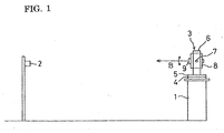
- FIG. 1 is a side view showing a setting condition of an automatic tracking apparatus for a reflector according to the present invention.
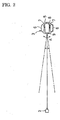
- FIG. 2 is a plan view showing a setting condition of an automatic tracking apparatus for a reflector according to the present invention.
- FIG. 3 is an explanation view showing an optical portion of an automatic tracking apparatus for a reflector according to the present invention.
- FIG. 4 is a view showing an example of an illumination area of measurement light by an illumination portion according to the present invention.
- FIG. 5 is an explanation view showing an example of a reflection light image formed in an image sensor according to the present invention.
- FIG. 6 is a circuit block diagram showing an example of a processing circuit according to the embodiment of the present invention.
- FIG. 7 is a timing chart explaining timing for taking a signal out from the image sensor according to the present invention.
- FIG. 8A is a timing chart graph explaining a relationship between the light emitting timing signal and the light receiving signal, and also a graph indicating the emitting light output.
- FIG. 8B is a timing chart graph explaining a relationship between the light emitting timing signal and the light receiving signal, and also a graph indicating the light receiving output.
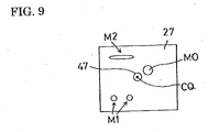
- FIG. 9 is an explanation view showing an example of a light image reflected on the image sensor.
-
- In FIG.1,
reference numeral 1 denotes a surveying pedestal and reference numeral 2 a corner cube as a reflector placed at a point to be measured. Thissurveying pedestal 1 is provided with a surveying machine 3. This surveying machine 3 comprises afixing board 4 and ahorizontal rotation portion 5. Thefixing board 4 is provided with a known rotation mechanism (not shown) for rotating thehorizontal rotation portion 5. - As shown in FIG. 2, the
horizontal rotation portion 5 is rotated in the direction of arrow A relative to thefixing board 4. Thehorizontal rotation portion 5 comprises a supporting portion or carryingportion 6. A verticaldirection rotation shaft 7 is mounted on the supportingportion 6, and a known rotation mechanism (not shown) for rotating the verticaldirection rotation shaft 7 is provided in the inside of the supportingportion 6. Asurveying machine body 8 is mounted on the verticaldirection rotation shaft 7. Thesurveying machine body 8 is rotated in the horizontal direction by a rotation of thehorizontal rotation portion 5, and also is rotated in the vertical direction by a rotation of the verticaldirection rotation shaft 7 shown by the arrow B in FIG. 1. - In the
surveying machine body 8, as shown in FIG. 3, there are provided with a collimationoptical portion 9, a range findingoptical portion 10, anillumination portion 11, and alight receiving portion 12. The collimationoptical portion 9 is one for collimating thecorner cube 2, and comprises anobjective lens 13, areflection mirror 14, adichroic prism 15, a focusinglens 16, a Porroprism 17, afocal point mirror 18, and aneyepiece 19. - The
objective lens 13 includes apenetration part 20. The reflection mirror 14 constructs part of theillumination portion 11. Theillumination portion 11 comprises alaser diode 21, acollimator lens 22, andreflection mirrors laser diode 21 ejaculates an infrared laser beam P (900nm of wave length) as a measurement light, and the infrared laser beam P is changed to a parallel pencil by thecollimator lens 22. - The
reflection mirror 14 is for bringing an optical axis O1 of theillumination portion 11 into line with an optical axis O, and has a reflection face 14a. The infrared laser beam P is reflected on thereflection mirrors objective lens 13, and then is emitted to an outside through thepenetration portion 20, and is illuminated toward thecorner cube 2. FIG. 4 shows an illumination area Q1 of the infrared laser beam P. - The infrared laser beam P which is reflected on the
corner cube 2 is condensed by the whole area of theobjective lens 13, and is led to thedichroic prism 15. Thedichroic prism 15 includesreflection faces - The
reflection face 15a reflects the infrared laser beam P toward thelight receiving portion 12. Thelight receiving portion 12 comprises animage sensor 27. Anoptical axis 02 of thelight receiving portion 12 is coincided with the optical axis O of theobjective lens 13. - The
range finding portion 10 is composed of alight projecting system 29 and alight receiving system 30, and thelight projecting system 29 includes alaser light source 31 and thelight receiving system 30 includes aphotosensitive device 33. Atriangle prism 32 is disposed between thelight projecting system 29 and thelight receiving system 30. Thelaser light source 31 emits an infrared laser light wave as a distance measuring luminous flux. A wave length of its infrared laser light wave is 800 nm, and the wave length is different from the wave length of the infrared laser light P. - The infrared laser light wave is reflected on a
reflection face 32a of thetriangle prism 32, and is led to thereflection face 15b of thedichroic prism 15. Thisreflection face 15b transmits light of a visualized area, and reflects light of an infrared area including light with a wavelength of 800nm. - The infrared laser light wave which is led to the
reflection face 15b is emitted as a plane wave to the outside of thesurveying machine body 8 by passing through alower half area 34 of theobjective lens 13 after transmitting thereflection face 15a. The infrared laser light wave is reflected on thecorner cube 2, and returns to theobjective lens 13, and is condensed by anupper half area 35 of theobjective lens 13. After that, the infrared laser light wave is led to thereflection face 15b after transmitting thereflection face 15a of thedichroic prism 15, and then is led to areflection face 32b of thetriangle prism 32 by thisreflection face 15b, and is reflected on thisreflection face 32b, and then is converged on thephotosensitive device 33. - An output of light receiving of the
photosensitive device 33 is input in a knownmeasuring circuit 36, and themeasuring circuit 36 calculates a distance from thesurveying machine body 8 to acorner cube 2. The distance from the surveying machine body to thecorner cube 2 is thereby measured. - A luminous flux of a visualized area is led to the
focal point mirror 18 through theobjective lens 13, thedichroic prism 15, the focusinglens 16, and the Porroprism 17, and including a vicinity of thecorner cube 2, an image of the vicinity is formed on thefocal point mirror 18 by adjusting the focusinglens 16. A worker can collimate thecorner cube 2 by looking into a visualized image, which is imaged on thefocal point mirror 18 through theeyepiece 19. - As shown in FIG. 5, a reflection light image M0 by the reflection light of the measurement light from the
corner cube 2 is formed in the area of theimage sensor 27. An output of theimage sensor 27 is input in aprocessing circuit 37 shown in FIG. 6. Theprocessing circuit 37 comprises acentral processing device 38 as arithmetic means and a circuit for generating a timing signal 39. The circuit for generating the timing signal 39 outputs a light emitting timing pulse signal P1 toward a laser diode driver circuit or a light emittingelement driver circuit 40, and also outputs a vertical synchronization signal V1, a horizontal synchronization signal H1, a transfer gate pulse signal P2, and an electronic shutter pulse P3 as shown FIG. 7 toward adriver circuit 41. - The light of the
laser diode 21 is made to emit pulsed light by a signal from the light emittingelement driver circuit 40 during an electronic shutter pulse P3 or an accumulation time is stopped within the period of one field. The frequency of the light emission pulse is modulated such as amplitude modulation. FIG. 8A indicates a light emission pulse train PQ modulated by the laserdiode driver circuit 40. - The
driver circuit 41 scans each pixel in theimage sensor 27 based on the vertical synchronization signal V1, the horizontal synchronization signal H1, the transfer gate pulse signal P2, and the electronic shutter pulse P3. The scanning frequency is 1/60Hz or 1/50Hz at each filed. - The output signal (quantity of light signal or luminance signal) of each pixel is input in a
sample hold circuit 42, and is input in an A/D conversion circuit 44 after being amplified by anamplification circuit 43. The A/D conversion circuit 44 outputs the quantity of light signal of each pixel as 8 bits data toward aflame memory 45 as a storing portion. - When measurement is conducted outside of a house, in order to reduce outside light as much as possible, it is desirable to adjust the quantity of light by adjusting a mechanical aperture stop (not shown), the gain of the
amplification circuit 43, and the time of the electronic shutter pulse. - The central
arithmetic processing device 38 reads out the quantity of light signal based on each pixel from theflame memory 45, and calculates positions of the center of gravity G (Xg, Yg), and based on the positions of the center of gravity G (Xg, Yg) obtained like this, the centralarithmetic processing device 38 outputs a rotation control signal toward the rotation mechanism so as that the surveyingmachine body 8 turns to thecorner cube 2. In other words, the centralarithmetic processing device 38 rotates and controls the surveyingmachine body 8 so as that the positions of the center of gravity G of the reflection light image M0 is coincided with a center CQ of theimage sensor 27. - The
light receiving portion 12 is provided with abeam splitter 46 and alight receiving sensor 47. Thelight receiving sensor 47 and theimage sensor 27 are disposed in a conjugated position through thebeam splitter 46. The area of thelight receiving sensor 47 is smaller than the area of theimage sensor 27, and has a function for receiving the quantity of light in the vicinity area including the image center CQ. - An output of the light receiving of the
light receiving sensor 47 is input in asynchronization detecting circuit 49 through anamplifier 48. Thesynchronization detecting circuit 49 synchronously detects the output of light receiving of thelight receiving sensor 47 based on the modulation signal from the light emittingelement driver 40. FIG. 8B indicates the output of the light receiving of thelight receiving sensor 47. When a modulation frequency of the light emittingelement deriver 40 and a frequency of the output of the light receiving from thelight receiving sensor 47 are coincided, thesynchronization detecting circuit 49 outputs the coincided signal toward thecentral processing device 38, and thecentral processing device 38 can judge whether or not an object existed on the optical axis O is the reflector, in other words, whether or not the light image acquired on the image center CQ in theimage sensor 27 is the reflection light image form thereflector 2 can be judged. - As shown in FIG. 9, for example, when the measurement is conducted an outside of a house, light images such as a light image M1 from a head light, a light image M2 from reflection light of sun, and the light image MO form a reflector are appeared in the
image sensor 27, however, the modulation is not applied to the light image M2 from the reflection light of sun and the light image M1 from the head light. Therefore, even thought these light images M1, M2 are positioned in the center CQ of theimage sensor 27, it is possible to avoid that the reflection light image M0 from thereflector 2 is misjudged as these light images M1, M2. - Moreover, for example, there is a case that a head light is crossed the backside of the
reflector 2, but in this case, only thereflector 2 can be securely tracked. - According to the present invention, an automatic tracking apparatus for a reflector even thought an illumination portion for illuminating measurement light toward a reflector and a light receiving portion having an image sensor for receiving a reflection light image of the measurement light illuminated toward the reflector are provided in a surveying machine body, the automatic tracking apparatus can carry out tracking without being disturbed.
- In other words, according to the present invention, when a light image other than the reflection light image is existed in the vicinity of the center of the image sensor, the reflection light image from the reflector can be securely distinguished from the other light image and can be tracked.
- This distinguish judgment can be carried out within every scanning period of one field of the image sensor, so the distinguish judgment is conducted almost in a real time; therefore, a tracking error can be further reduced.
Claims (5)
- An automatic tracking apparatus for a reflector comprising:characterized in that said light receiving portion (12) is provided with a light receiving sensor (47) having a smaller area than the area of said image sensor on said light receiving optical axis and also in a conjugated position with said image sensor (27), and said arithmetic means (38) distinguishes said reflector (2) based on an output of said light receiving sensor (47).a surveying machine body (8);an illumination portion (11) is disposed in said surveying machine body (8) for illuminating a measurement light toward a reflector (2);a light receiving portion (12) which is disposed in said surveying machine body (8) and which has an image sensor (27) for receiving a reflection light image of the measurement light illuminated toward said reflector (2);arithmetic means (38) for calculating a position of the reflection light image from said reflector (2) in an area of said image sensor (27); anda rotation mechanism for rotating said surveying machine body (8) so as to position said reflector (2) on a light receiving optical axis of said light receiving portion based on the position obtained by said arithmetic means (38),
- The automatic tracking apparatus for the reflector according to Claim 1, characterized in that said illumination portion (11) outputs a modulated pulsed light, and said light receiving portion (12) is provided with a synchronization detecting circuit (49) for synchronously detecting the output of said light receiving sensor (47) based on said modulated pulsed light.
- The automatic tracking apparatus for the reflector according to Claim 1, characterized in that said image sensor (27) and said light receiving sensor (47) are disposed in the conjugated position through a beam splitter (46), and said light receiving sensor (47) receives a quantity of light in the vicinity area of the image center of said image sensor (27).
- The automatic tracking apparatus for the reflector according to Claim 1, characterized in that said illumination portion (11) emits a modulated pulsed light which is a measurement light in an accumulation time during one field of said image sensor, and said image sensor (27) detects the position of the received modulated pulsed light, and the light receiving sensor (47) judges based on the modulation of the pulsed light whether or not the light received by the light receiving sensor (27) is one from the reflector (2).
- The automatic tracking apparatus for the reflector according to Claims 1 and 2, characterized in that based on the modulated pulsed light received by said image sensor (27), the surveying machine body (8) is rotated so as the position of said pulsed light to be the center of said image sensor (27), and tracks based on the judgment of said light receiving sensor (47).
Applications Claiming Priority (2)
| Application Number | Priority Date | Filing Date | Title |
|---|---|---|---|
| JP2002339347 | 2002-11-22 | ||
| JP2002339347A JP4127503B2 (en) | 2002-11-22 | 2002-11-22 | Reflector automatic tracking device |
Publications (3)
| Publication Number | Publication Date |
|---|---|
| EP1422500A2 true EP1422500A2 (en) | 2004-05-26 |
| EP1422500A3 EP1422500A3 (en) | 2008-11-05 |
| EP1422500B1 EP1422500B1 (en) | 2019-05-22 |
Family
ID=32212140
Family Applications (1)
| Application Number | Title | Priority Date | Filing Date |
|---|---|---|---|
| EP03090397.5A Expired - Lifetime EP1422500B1 (en) | 2002-11-22 | 2003-11-20 | Automatic reflector tracking apparatus |
Country Status (3)
| Country | Link |
|---|---|
| US (1) | US7072032B2 (en) |
| EP (1) | EP1422500B1 (en) |
| JP (1) | JP4127503B2 (en) |
Cited By (1)
| Publication number | Priority date | Publication date | Assignee | Title |
|---|---|---|---|---|
| EP1876416A2 (en) * | 2006-07-07 | 2008-01-09 | Kabushiki Kaisha TOPCON | Surveying apparatus |
Families Citing this family (22)
| Publication number | Priority date | Publication date | Assignee | Title |
|---|---|---|---|---|
| US8060344B2 (en) * | 2006-06-28 | 2011-11-15 | Sam Stathis | Method and system for automatically performing a study of a multidimensional space |
| JP5469894B2 (en) * | 2008-07-05 | 2014-04-16 | 株式会社トプコン | Surveying device and automatic tracking method |
| US9482755B2 (en) | 2008-11-17 | 2016-11-01 | Faro Technologies, Inc. | Measurement system having air temperature compensation between a target and a laser tracker |
| JP2012530908A (en) * | 2009-06-23 | 2012-12-06 | ライカ・ジオシステムズ・アクチェンゲゼルシャフト | Coordinate measuring device |
| WO2010148526A1 (en) * | 2009-06-23 | 2010-12-29 | Leica Geosystem Ag | Tracking method and measuring system having a laser tracker |
| EP2381269A1 (en) | 2010-04-13 | 2011-10-26 | Leica Geosystems AG | Coordinate measuring device with automated targeting |
| US9772394B2 (en) | 2010-04-21 | 2017-09-26 | Faro Technologies, Inc. | Method and apparatus for following an operator and locking onto a retroreflector with a laser tracker |
| US8724119B2 (en) | 2010-04-21 | 2014-05-13 | Faro Technologies, Inc. | Method for using a handheld appliance to select, lock onto, and track a retroreflector with a laser tracker |
| US9400170B2 (en) | 2010-04-21 | 2016-07-26 | Faro Technologies, Inc. | Automatic measurement of dimensional data within an acceptance region by a laser tracker |
| US9377885B2 (en) | 2010-04-21 | 2016-06-28 | Faro Technologies, Inc. | Method and apparatus for locking onto a retroreflector with a laser tracker |
| US8422034B2 (en) | 2010-04-21 | 2013-04-16 | Faro Technologies, Inc. | Method and apparatus for using gestures to control a laser tracker |
| US8537371B2 (en) | 2010-04-21 | 2013-09-17 | Faro Technologies, Inc. | Method and apparatus for using gestures to control a laser tracker |
| US8619265B2 (en) | 2011-03-14 | 2013-12-31 | Faro Technologies, Inc. | Automatic measurement of dimensional data with a laser tracker |
| GB2511236B (en) | 2011-03-03 | 2015-01-28 | Faro Tech Inc | Target apparatus and method |
| GB2504890A (en) | 2011-04-15 | 2014-02-12 | Faro Tech Inc | Enhanced position detector in laser tracker |
| US9482529B2 (en) | 2011-04-15 | 2016-11-01 | Faro Technologies, Inc. | Three-dimensional coordinate scanner and method of operation |
| US9686532B2 (en) | 2011-04-15 | 2017-06-20 | Faro Technologies, Inc. | System and method of acquiring three-dimensional coordinates using multiple coordinate measurement devices |
| US9164173B2 (en) | 2011-04-15 | 2015-10-20 | Faro Technologies, Inc. | Laser tracker that uses a fiber-optic coupler and an achromatic launch to align and collimate two wavelengths of light |
| CN104094081A (en) | 2012-01-27 | 2014-10-08 | 法罗技术股份有限公司 | Inspection method with barcode identification |
| JP6129475B2 (en) * | 2012-02-29 | 2017-05-17 | 三菱重工業株式会社 | Monitoring device and monitoring method |
| US9041914B2 (en) | 2013-03-15 | 2015-05-26 | Faro Technologies, Inc. | Three-dimensional coordinate scanner and method of operation |
| US9395174B2 (en) | 2014-06-27 | 2016-07-19 | Faro Technologies, Inc. | Determining retroreflector orientation by optimizing spatial fit |
Citations (2)
| Publication number | Priority date | Publication date | Assignee | Title |
|---|---|---|---|---|
| WO1990012284A1 (en) | 1989-04-06 | 1990-10-18 | Geotronics Ab | An arrangement for performing position determination |
| EP0797076A2 (en) | 1996-03-18 | 1997-09-24 | Kabushiki Kaisha Topcon | Surveying system |
Family Cites Families (22)
| Publication number | Priority date | Publication date | Assignee | Title |
|---|---|---|---|---|
| US4107530A (en) * | 1966-01-26 | 1978-08-15 | Lockheed Aircraft Corporation | Infrared acquisition device |
| US3652164A (en) * | 1970-05-01 | 1972-03-28 | Polaroid Corp | Relative back focus monitoring method and apparatus |
| US3730629A (en) * | 1970-12-24 | 1973-05-01 | Bell Telephone Labor Inc | Time resolved spectrometer |
| US3768910A (en) * | 1972-05-25 | 1973-10-30 | Zygo Corp | Detecting the position of a surface by focus modulating the illuminating beam |
| US4150285A (en) * | 1977-12-27 | 1979-04-17 | United Technologies Corporation | Remote optical display designator |
| DE3485541D1 (en) * | 1983-12-16 | 1992-04-09 | Sony Corp | DEVICE FOR DISK PLAYBACK. |
| US4713533A (en) * | 1986-01-03 | 1987-12-15 | Westinghouse Electric Corp. | Concentric detector array and associated hybrid signal processing for coarse and fine electro-optical tracking |
| US5216480A (en) * | 1987-12-26 | 1993-06-01 | Asahi Kogaku Kogyo K.K. | Surveying instrument |
| JP2994452B2 (en) * | 1990-10-30 | 1999-12-27 | 株式会社トプコン | Surveying instrument |
| JP3189368B2 (en) * | 1992-04-10 | 2001-07-16 | 株式会社デンソー | Posture position measuring device |
| JP2793740B2 (en) | 1992-05-21 | 1998-09-03 | 株式会社トプコン | Surveying instrument |
| US5600123A (en) * | 1993-02-17 | 1997-02-04 | Litton Systems, Inc. | High-resolution extended field-of-view tracking apparatus and method |
| JPH07198382A (en) * | 1993-12-28 | 1995-08-01 | Nikon Corp | Laser surveying system |
| JPH08237203A (en) * | 1995-02-23 | 1996-09-13 | Fujitsu Ltd | Optical filter array, optical transmitter and optical transmission system |
| JPH08233553A (en) * | 1995-02-28 | 1996-09-13 | Canon Inc | Optical heterodyne interferometer |
| US6359685B1 (en) * | 1997-02-14 | 2002-03-19 | Jds Uniphase Corporation | Apparatus and method for generation of optical signals |
| JP3017983B2 (en) * | 1997-11-19 | 2000-03-13 | 株式会社ケンウッド | Synchronous acquisition circuit |
| US6587948B1 (en) * | 1998-02-13 | 2003-07-01 | Sony Corporation | Recording apparatus, recording medium, playback apparatus, recording method and playback method |
| JP2000050145A (en) * | 1998-05-26 | 2000-02-18 | Matsushita Electric Works Ltd | Automatic tracking device |
| WO2000019673A1 (en) * | 1998-09-28 | 2000-04-06 | Matsushita Electric Industrial Co., Ltd. | Vsb receiver |
| JP4210792B2 (en) * | 1999-06-15 | 2009-01-21 | 株式会社トプコン | Position detection device |
| JP4930742B2 (en) * | 2001-03-29 | 2012-05-16 | 株式会社トプコン | Position detection device |
-
2002
- 2002-11-22 JP JP2002339347A patent/JP4127503B2/en not_active Expired - Fee Related
-
2003
- 2003-11-20 EP EP03090397.5A patent/EP1422500B1/en not_active Expired - Lifetime
- 2003-11-20 US US10/718,230 patent/US7072032B2/en active Active
Patent Citations (2)
| Publication number | Priority date | Publication date | Assignee | Title |
|---|---|---|---|---|
| WO1990012284A1 (en) | 1989-04-06 | 1990-10-18 | Geotronics Ab | An arrangement for performing position determination |
| EP0797076A2 (en) | 1996-03-18 | 1997-09-24 | Kabushiki Kaisha Topcon | Surveying system |
Cited By (2)
| Publication number | Priority date | Publication date | Assignee | Title |
|---|---|---|---|---|
| EP1876416A2 (en) * | 2006-07-07 | 2008-01-09 | Kabushiki Kaisha TOPCON | Surveying apparatus |
| EP1876416A3 (en) * | 2006-07-07 | 2008-10-29 | Kabushiki Kaisha TOPCON | Surveying apparatus |
Also Published As
| Publication number | Publication date |
|---|---|
| EP1422500A3 (en) | 2008-11-05 |
| EP1422500B1 (en) | 2019-05-22 |
| US7072032B2 (en) | 2006-07-04 |
| JP4127503B2 (en) | 2008-07-30 |
| JP2004170356A (en) | 2004-06-17 |
| US20040100628A1 (en) | 2004-05-27 |
Similar Documents
| Publication | Publication Date | Title |
|---|---|---|
| US7072032B2 (en) | Automatic tracking apparatus for reflector | |
| US7274802B2 (en) | Automatic tracking apparatus for reflector | |
| US6957493B2 (en) | Automatic tracking apparatus for reflector | |
| JP7084705B2 (en) | Surveying device | |
| JP4499261B2 (en) | Tachymeter telescope | |
| US7319512B2 (en) | Surveying instrument | |
| JP4832311B2 (en) | Proximity detector | |
| JP2006276012A (en) | Measuring system for obtaining six degrees of freedom of object | |
| US7301617B2 (en) | Surveying apparatus | |
| US20140320866A1 (en) | Shape Measuring Apparatus | |
| US11913786B2 (en) | Surveying instrument | |
| JP6892734B2 (en) | Light wave distance measuring device | |
| US20080007723A1 (en) | Surveying apparatus | |
| US20030043287A1 (en) | Three-dimensional image capturing device | |
| JP3609901B2 (en) | Ranging device | |
| JPH0783657A (en) | Surveying instrument | |
| JP6867736B2 (en) | Light wave distance measuring device | |
| US6897421B2 (en) | Optical inspection system having an internal rangefinder | |
| JP2018048868A (en) | Scanner device and surveying device | |
| JPS61161479A (en) | Measuring device of height of liquid surface | |
| JP2021063678A (en) | Measurement device | |
| JPH09297261A (en) | Image pickup device | |
| JPH04166786A (en) | Optical device for emitting and receiving light | |
| JPH06258433A (en) | Target locator | |
| UA114797C2 (en) | DEVICES FOR DETERMINATION OF MECHANICAL ELEMENTS |
Legal Events
| Date | Code | Title | Description |
|---|---|---|---|
| PUAI | Public reference made under article 153(3) epc to a published international application that has entered the european phase |
Free format text: ORIGINAL CODE: 0009012 |
|
| AK | Designated contracting states |
Kind code of ref document: A2 Designated state(s): AT BE BG CH CY CZ DE DK EE ES FI FR GB GR HU IE IT LI LU MC NL PT RO SE SI SK TR |
|
| AX | Request for extension of the european patent |
Extension state: AL LT LV MK |
|
| PUAL | Search report despatched |
Free format text: ORIGINAL CODE: 0009013 |
|
| AK | Designated contracting states |
Kind code of ref document: A3 Designated state(s): AT BE BG CH CY CZ DE DK EE ES FI FR GB GR HU IE IT LI LU MC NL PT RO SE SI SK TR |
|
| AX | Request for extension of the european patent |
Extension state: AL LT LV MK |
|
| 17P | Request for examination filed |
Effective date: 20090417 |
|
| AKX | Designation fees paid |
Designated state(s): CH DE LI |
|
| 17Q | First examination report despatched |
Effective date: 20100715 |
|
| GRAP | Despatch of communication of intention to grant a patent |
Free format text: ORIGINAL CODE: EPIDOSNIGR1 |
|
| INTG | Intention to grant announced |
Effective date: 20181218 |
|
| RIN1 | Information on inventor provided before grant (corrected) |
Inventor name: SAITO, MASAHIRO Inventor name: YAMAGUCHI, SHINJI Inventor name: KUMAGAI, KAORU |
|
| RIC1 | Information provided on ipc code assigned before grant |
Ipc: G01C 15/00 20060101AFI20040227BHEP |
|
| GRAS | Grant fee paid |
Free format text: ORIGINAL CODE: EPIDOSNIGR3 |
|
| GRAA | (expected) grant |
Free format text: ORIGINAL CODE: 0009210 |
|
| AK | Designated contracting states |
Kind code of ref document: B1 Designated state(s): CH DE LI |
|
| REG | Reference to a national code |
Ref country code: CH Ref legal event code: EP |
|
| REG | Reference to a national code |
Ref country code: DE Ref legal event code: R096 Ref document number: 60352032 Country of ref document: DE |
|
| REG | Reference to a national code |
Ref country code: CH Ref legal event code: NV Representative=s name: VALIPAT S.A. C/O BOVARD SA NEUCHATEL, CH |
|
| PGFP | Annual fee paid to national office [announced via postgrant information from national office to epo] |
Ref country code: DE Payment date: 20191105 Year of fee payment: 17 |
|
| REG | Reference to a national code |
Ref country code: DE Ref legal event code: R097 Ref document number: 60352032 Country of ref document: DE |
|
| PLBE | No opposition filed within time limit |
Free format text: ORIGINAL CODE: 0009261 |
|
| STAA | Information on the status of an ep patent application or granted ep patent |
Free format text: STATUS: NO OPPOSITION FILED WITHIN TIME LIMIT |
|
| PGFP | Annual fee paid to national office [announced via postgrant information from national office to epo] |
Ref country code: CH Payment date: 20191116 Year of fee payment: 17 |
|
| 26N | No opposition filed |
Effective date: 20200225 |
|
| REG | Reference to a national code |
Ref country code: DE Ref legal event code: R119 Ref document number: 60352032 Country of ref document: DE |
|
| REG | Reference to a national code |
Ref country code: CH Ref legal event code: PL |
|
| PG25 | Lapsed in a contracting state [announced via postgrant information from national office to epo] |
Ref country code: LI Free format text: LAPSE BECAUSE OF NON-PAYMENT OF DUE FEES Effective date: 20201130 Ref country code: CH Free format text: LAPSE BECAUSE OF NON-PAYMENT OF DUE FEES Effective date: 20201130 |
|
| PG25 | Lapsed in a contracting state [announced via postgrant information from national office to epo] |
Ref country code: DE Free format text: LAPSE BECAUSE OF NON-PAYMENT OF DUE FEES Effective date: 20210601 |