BACKGROUND OF THE INVENTION
-
The present invention relates to an image processing system, a projector, a
portable device, and an image processing method that are capable of correcting
keystone distortion.
-
Various different methods have been proposed for correcting keystone distortion
that is generated in images projected by a projector.
-
One method detects the inclination of the projector and automatically corrects
keystone distortion in the vertical direction, by way of example.
-
However, this method does not enable the user to correct keystone distortion in
the horizontal direction.
-
For that reason, one method of correcting keystone distortion in the horizontal
direction involves the user correcting the keystone distortion manually by pressing a
correction switch on a remote controller while viewing the image.
-
However, the manual correction of the keystone distortion is troublesome to the
user, making it difficult to perform suitable correction manually.
-
In the light of the above problem, methods have been proposed for correcting
image distortion automatically, such as that disclosed in Japanese Patent Application No.
2001-036086 (Japanese Patent Publication No. 2002-112148).
-
However, this method only discloses a method of correcting keystone distortion
by detecting the distance up to the installation plane of the projector and the inclinations
in the horizontal and vertical directions with respect to the horizontal plane of the
projector.
-
For that reason, that method is based on the premise that the projection screen is
positioned facing the projector, as stated in that application.
-
If the projector is positioned in a direction at an angle to the projection screen,
however, keystone distortion is generated in the horizontal direction (sideways
direction).
-
It is therefore difficult to use that published method to correct keystone
distortion in the horizontal direction both automatically and appropriately.
BRIEF SUMMARY OF THE INVENTION
-
The present invention was devised in the light of the above-described technical
problems, and may provide an image processing system, a projector, a portable device,
and an image processing method that make it possible to correct keystone distortion,
particularly keystone distortion in the horizontal direction, both automatically and
appropriately.
-
In order to resolve the above-described technical problems, according to a first
aspect of the present invention, there is provided an image processing system
comprising:
- sensing means for sensing a projection area on which an image is projected and
outputting sensing information;
- histogram generation means for generating histogram information that expresses
histograms of the numbers of pixels of the sensed image in each of the vertical and
horizontal directions, based on the sensing information;
- direction determination means for generating direction information, based on an
angle between a normal direction orthogonal to the projection area from a sensing
position and a projected image direction toward a central portion of the projected image
from the sensing position; and
- keystone distortion correction means for correcting keystone distortion of the
projected image, based on the histogram information and the direction information.
-
-
According to a second aspect of the present invention, there is provided a
projector comprising:
- projection means for projecting an image;
- receiving means for receiving histogram information that expresses histograms
of the numbers of pixels of the sensed image in each of the vertical and horizontal
directions, based on sensing information obtained by sensing a projection area on which
the projected image is projected, and direction information based on an angle between a
normal direction orthogonal to a projection area from a sensing position and a projected
image direction toward a central portion of the projected image from the sensing
position; and
- keystone distortion correction means for correcting keystone distortion of the
projected image, based on the histogram information and the direction information.
-
-
According to a third aspect of the present invention, there is provided a portable
device comprising:
- sensing means for sensing a projection area on which an image is projected;
- histogram generation means for generating histogram information that expresses
histograms of the numbers of pixels of the sensed image in each of the vertical and
horizontal directions, based on sensing information obtained by the sensing means;
- direction determination means for determining direction information based on an
angle between a normal direction orthogonal to the projection area from a sensing
position and a projected image direction toward a central portion of the projected image
from the sensing position; and
- transmitter means for correcting keystone distortion of the projected image,
based on the histogram information and the direction information, and transmitting the
histogram information and the direction information to an image display device that
projects the projected image.
-
-
According to a fourth aspect of the present invention, there is provided an image
processing method comprising:
- sensing a projection area on which an image is projected and outputting sensing
information;
- generating histogram information that expresses histograms of the numbers of
pixels of the sensed image in each of the vertical and horizontal directions, based on the
sensing information;
- detecting a normal direction orthogonal to the projection area from a sensing
position;
- detecting a projected image direction toward a central portion of the projected
image from the sensing position;
- generating direction information, based on an angle between the normal
direction and the projected image direction; and
- correcting keystone distortion of the projected image, based on the histogram
information and the direction information.
-
-
The image processing system and others according to the present invention
makes it possible to determine keystone distortion by sensing. They can convert the
magnitude of the distortion into numerical values by converting the sensing information
into histograms. They can also determine the relative displacement between the sensing
direction and the projection direction by determining the angle.
-
Furthermore, the image processing system and others can correct not only
keystone distortion in the vertical direction but also keystone distortion in the horizontal
direction, both automatically and appropriately, by correcting the keystone distortion,
based on histogram information that expresses the distortion and direction information
that expresses relative displacement between the sensing direction and the projection
direction.
-
The image processing system may comprise:
- a portable device having the sensing means, the histogram generation means,
and the direction determination means; and
- an image display device having the keystone distortion correction means and
projection means for projecting an image,
wherein the keystone distortion correction means may include:
- vertical keystone distortion correction means having inclination detection means
for detecting the inclination of the image display device, for correcting keystone
distortion in the vertical direction; and
- horizontal keystone distortion correction means for correcting keystone
distortion in the horizontal direction, based on the histogram information and the
direction information.
-
-
In the projector, the keystone distortion correction means may include:
- vertical keystone distortion correction means having inclination detection means
for detecting the inclination of the projection means, for correcting keystone distortion
in the vertical direction; and
- horizontal keystone distortion correction means for correcting keystone
distortion in the horizontal direction, based on the histogram information and the
direction information.
-
-
The image processing method may comprise:
- detecting inclination of an image display device;
- correcting keystone distortion in the vertical direction, based on the detected
inclination; and
- correcting keystone distortion in the horizontal direction, based on the histogram
information and the direction information.
-
-
The keystone distortion in the horizontal direction is affected by the relative
positional relationship between the image display device and the projection area. In
contrast thereto, the keystone distortion in the vertical direction is mainly affected by
the inclination of the image display device.
-
The image processing system and others can therefore correct the keystone
distortion as appropriate, by correcting the keystone distortion in the vertical direction,
based on the inclination of the image display device, and by correcting the keystone
distortion in the horizontal direction, based on histogram information and direction
information that reflect the position of the projection area.
-
According to an fifth aspect of the present invention, there is provided an image
processing system comprising:
- light projection means for projecting light of a distortion-free and predetermined
shape into a projection area;
- sensing means for outputting sensing information obtained by sensing the
projection area into which the light of the predetermined shape is projected, from a
projection position of a projection section for projecting an image;
- area extraction means for extracting coordinates of the light of the
predetermined shape in a sensed area, based on the sensing information; and
- keystone distortion correction means for converting the coordinates of the light
of the predetermined shape in the sensed area into coordinates for projection in a spatial
light modulator of the projection section, and correcting keystone distortion by mapping
coordinates of an input image into the projection coordinates.
-
-
The image processing system may comprise:
- a portable device having the light projection means; and
- an image display device having the sensing means, the keystone distortion
correction means, and the projection section.
-
-
According to a sixth aspect of the present invention, there is provided a projector
comprising:
- sensing means for outputting sensing information obtained by sensing a
projection area into which light of a distortion-free and predetermined shape is projected,
from a projection position of a projection section for projecting an image;
- area extraction means for extracting coordinates of the light of the
predetermined shape in a sensed area, based on the sensing information;
- keystone distortion correction means for converting the coordinates of the light
of the predetermined shape in the sensed area into coordinates for projection in a spatial
light modulator of the projection section, and correcting keystone distortion by mapping
coordinates of an input image into the projection coordinates; and
- the projection section.
-
-
According to a seventh aspect of the present invention, there is provided an
image processing method comprising:
- projecting light of a distortion-free and predetermined shape into a projection
area;
- outputting sensing information obtained by sensing the projection area into
which the light of the predetermined shape is projected, from a projection position of a
projection section for projecting an image;
- extracting coordinates of the light of the predetermined shape in a sensed area,
based on the sensing information; and
- converting the coordinates of the light of the predetermined shape in the sensed
area into coordinates for projection in a spatial light modulator of the projection section,
and correcting keystone distortion by mapping coordinates of an input image into the in
the sensed area projection coordinates.
-
-
The image processing system and others according to the present invention
makes it possible to determine coordinates of light of a distortion-free and
predetermined shape that is projected into a projection area by sensing.
-
In other words, the coordinates of the light of the predetermined shape can be
taken as coordinates of a distortion-free image, and thus a distortion-free image can be
projected during image projection by mapping the coordinates of an input image into
those coordinates.
-
This makes it possible to correct keystone distortion in the horizontal direction
both automatically and appropriately.
-
In the image processing system and the projector, the predetermined shape may
be rectangular or square;
the area extraction means may extract coordinates of four comers of the light of
the predetermined shape; and
the keystone distortion correction means may convert the coordinates of the four
comers of the light of the predetermined shape in the sensed area into coordinates for
projection in a spatial light modulator of the projection section, and correct keystone
distortion by mapping the coordinates of an input image into an area formed by the
projection coordinates of the four comers.
-
In the image processing method, the predetermined shape may be rectangular or
square; and the method may include:
- extracting coordinates of four comers of the light of the predetermined shape
when coordinates of the light of the predetermined shape in the sensed area are
extracted; and
- converting the coordinates of the four comers of the light of the predetermined
shape in the sensed area into coordinates for projection in the spatial light modulator of
the projection section, and correcting keystone distortion by mapping coordinates of an
input image into an area formed by the projection coordinates of the four comers, when
the keystone distortion is corrected.
-
-
This makes it possible for the image processing system and others to display an
image of a rectangular or square shape during the display of an input image, by
projecting light having a rectangular or square shape, converting coordinates of the four
comers of that rectangle or square into four coordinates for projection in a spatial light
modulator (such as a liquid crystal light valve), and mapping the coordinates of an input
image into an area formed by the four coordinates for projection.
-
This enables the image processing system and others to correct keystone
distortion both automatic
ally and appropriately.
BRIEF DESCRIPTION OF THE SEVERAL VIEWS OF THE DRAWING
-
- Fig. 1 is an overall conceptual view of an image processing system in
accordance with a first embodiment of the present invention;
- Fig. 2 is a schematic view of a projected image and histograms in accordance
with the first embodiment of the present invention;
- Fig. 3 is a functional block diagram of a projector in accordance with the first
embodiment of the present invention;
- Fig. 4 is a functional block diagram of a remote controller in accordance with
the first embodiment of the present invention;
- Fig. 5 is a flowchart of keystone distortion correction processing in accordance
with the first embodiment of the present invention;
- Fig. 6 is a hardware block diagram of the projector in accordance with the first
embodiment of the present invention;
- Fig. 7 is a schematic view of a projected image and a laser beam projected image
in accordance with a second embodiment of the present invention;
- Fig. 8 is a functional block diagram of a projector in accordance with the second
embodiment of the present invention;
- Fig. 9 is a functional block diagram of a remote controller in accordance with
the second embodiment of the present invention;
- Fig. 10 is a flowchart of the processing by the remote controller in accordance
with the second embodiment of the present invention; and
- Fig. 11 is a flowchart of the processing by the projector in accordance with the
second embodiment of the present invention.
-
DETAILED DESCRIPTION OF THE EMBODIMENTS
-
The present invention is described below, taking as an example the application
thereof to an image processing system that correct keystone distortion of a projected
image by using a projector that is an image display device and a remote controller that
is a portable device, with reference to the accompanying figures. Note that the
embodiments described below do not in any way limit the scope of the present
invention as laid out in the claims herein. In addition, the entirety of the configuration
described with reference to these embodiments is not limited to being essential
structural components of the present invention.
-
The description below concerns a first embodiment in which a remote controller
having a sensing means is used to sense a projection area and determine a direction, and
a projector corrects keystone distortion. It also concerns a second embodiment in which
a remote controller having a light projection means projects a rectangular laser beam
into a projection area, and a projector corrects keystone distortion by sensing the
projection area from the projection position.
First Embodiment
-
An overall conceptual view of an image processing system in accordance with
the first embodiment is shown in Fig. 1. A schematic view of a projected image 70 and
histograms in accordance with the first embodiment are shown in Fig. 2.
-
In the first embodiment, a projector 10 that is a type of image display device
projects an image from a position which is not directly in front of a projection area 30,
but directed forward and to the left from a state directly facing the projection area 30,
and which is also at a distance further to the right than a viewer 40 who is a user.
-
In such a case, the projected image 70 that the viewer 40 sees has a trapezoidal
shape such that the leftmost edge is the longest and the rightmost edge is the shortest, as
shown in Fig. 2.
-
With this embodiment, an imaging function is provided in a remote controller 20
that is a type of portable device manipulated by the viewer 40, enabling the remote
controller 20 to sense (form an image of) the projection area 30.
-
The remote controller 20 is also provided with a histogram processing function,
enabling the remote controller 20 to generate a histogram 80 of the numbers of pixels in
the horizontal direction and a histogram 82 of the numbers of pixels in the vertical
direction, for the projected image 70 in a captured image 60.
-
The remote controller 20 is further provided with a direction determination
function, enabling the remote controller 20 to generate direction information based on
an angle between a normal direction n for the orthogonal direction from a virtual
viewpoint position 50 to the projection area 30 and a projected image direction i from
the virtual viewpoint position 50 to a central portion of the projected image.
-
Note that the virtual viewpoint position 50 is a position that sets the viewpoint of
the viewer 40 in a virtual manner, by way of example. In the first embodiment, the
sensing position of the remote controller 20 becomes the virtual viewpoint position 50.
-
The projector 10 also has a keystone distortion correction function that corrects
any keystone distortion of the projected image 70, based on the histogram information
(the histogram 80 of the numbers of pixels in the horizontal direction and the histogram
82 of the numbers of pixels in the vertical direction) and the direction information.
-
The image processing system of this embodiment uses these functions to correct
any keystone distortion of the projected image 70 from consideration of the virtual
viewpoint position 50, both automatically and appropriately.
-
The description now turns to the functional blocks of the projector 10 for
implementing these functions.
-
A functional block diagram of the projector 10 in accordance with this
embodiment is shown in Fig. 3.
-
The projector 10 comprises an input signal processing section 110, a color
conversion section 120, an output signal processing section 130, an image projection
section 190, a keystone distortion correction section 140, and a receiver section 160.
-
The input signal processing section 110 converts an R1 signal, a G1 signal, and
a B1 signal (which form RGB signals in analog form that is a type of input image
information that is input from a personal computer (PC) or the like) into an R2 signal, a
G2 signal, and a B2 signal in digital form.
-
The input signal processing section 110 comprises an A/D converter section 112
that performs this analog-to-digital conversion and a resizing section 114 that functions
as part of a keystone distortion correction means to adjust the position and dimensions
of the projected image 70 by adjusting the input image signal.
-
A calibration signal generation section 150 generates an R2 signal, a G2 signal,
and a B2 signal in digital format that are used for displaying a calibration image.
-
Generating the calibration signals within the liquid-crystal projector in this
manner makes it possible for the liquid-crystal projector itself to perform the calibration,
without having to input calibration signals to the liquid-crystal projector from an
external input device such as a PC. Note that the configuration could also be such that
the calibration signal generation section 150 is not provided and the calibration image
signals are input from a PC or the like.
-
The color conversion section 120 outputs an R3 signal, a G3 signal, and a B3
signal having a color temperature that has been corrected on the basis of a standard
setting for the liquid-crystal projector, based on the R2 signal, G2 signal, and B2 signal
from the input signal processing section 110 or the calibration signal generation section
150.
-
The output signal processing section 130 comprises a D/A converter section 132.
The D/A converter section 132 converts the R3 signal, G3 signal, and B3 signal from
the color conversion section 120 into an R4 signal, a G4 signal, and a B4 signal in
analog format.
-
Note that the A/D converter section 112 and the D/A converter section 132 are
not necessary if the projector 10 uses only RGB signals in digital format.
-
The image projection section 190 that functions as projection means comprises a
spatial light modulator 192, a drive section 194 for driving the spatial light modulator
192, a light source 196, and a lens 198.
-
The drive section 194 drives the spatial light modulator 192, based on the R4
signal, G4 signal, and B4 signal from the output signal processing section 130. The
image projection section 190 projects light from the light source 196 through the spatial
light modulator 192 and the lens 198.
-
The receiver section 160 receives histogram information and direction
information that is transmitted from the remote controller 20.
-
The keystone distortion correction section 140 comprises a vertical keystone
distortion correction section 141, which has an inclination sensor 142 and which
corrects keystone distortion in the vertical direction, and a horizontal keystone
distortion correction section 143, which has a 3D-LUT 144 and which corrects keystone
distortion in the horizontal direction.
-
The inclination sensor 142 detects any inclination in the vertical direction of the
projector 10, and the vertical keystone distortion correction section 141 transmits a
vertical keystone distortion correction value that corresponds to that inclination (such as
an integer value from -n to n, similar to that for manual adjustment) to the resizing
section 114.
-
The horizontal keystone distortion correction section 143 takes the histogram
information and direction information that has been received by the receiver section 160,
selects a horizontal direction keystone distortion correction stored in the 3D-LUT 144
corresponding thereto (such as an integer value from -n to n, similar to that for manual
adjustment), and transmits the thus-selected horizontal direction keystone distortion
correction value to the resizing section 114.
-
The description now turns to the functional blocks for implementing the
functions of the remote controller 20.
-
A functional block diagram of the remote controller 20 in accordance with this
embodiment is shown in Fig. 4.
-
The remote controller 20 comprises an area sensor section 210 that functions as
sensing means to obtain the captured image 60 by using a sensor such as a CCD sensor
to image the projection area 30, a projected image area extraction section 220 that
extracts the projected image 70 from the captured image 60, and a histogram processing
section 230 that functions as histogram generation means for generating the histogram
80 of the numbers of pixels in the horizontal direction and the histogram 82 of the
numbers of pixels in the vertical direction of the projected image 70.
-
The projected image area extraction section 220 extracts a brightness detection
area of pixels of a maximum brightness, such as those of greater than 65% or 80%
brightness, from the captured image 60 as the projected image 70.
-
The histogram processing section 230 generates the totals of the numbers of
pixels for each scan line, when the projected image 70 is scanned in the horizontal
direction, as the histogram 80 of the numbers of pixels in the horizontal direction and
the totals of the numbers of pixels for each scan line, when the projected image 70 is
scanned in the vertical direction as the histogram 82 of the numbers of pixels in the
vertical direction, as shown in Fig. 2.
-
The histogram processing section 230 also calculates the ratio of an upper-base
length a to a lower-base length b from the histogram 80 of the numbers of pixels in the
horizontal direction and the sign of a value obtained by subtracting a lower-base length
d from an upper-base length c of the histogram 82 of the numbers of pixels in the
vertical direction, and transmits them as histogram information to a transmitter section
250.
-
In this case, the ratio of the upper-base length a to the lower-base length b of the
histogram 80 of the numbers of pixels in the horizontal direction represents the
magnitude of the distortion. The magnitude of the distortion increases as this ratio
increases, by way of example. The sign of the value obtained by subtracting the lower-base
length d from the upper-base length c of the histogram 82 of the numbers of pixels
in the vertical direction represents the direction of the distortion in either the right or left
direction.
-
The histogram information can therefore be termed information that represents
keystone distortion as numerical values.
-
The remote controller 20 comprises a direction determination section 240 having
a direction sensor 242, and the transmitter section 250 that transmits histogram
information comprising the histogram 80 of the numbers of pixels in the horizontal
direction and the histogram 82 of the numbers of pixels in the vertical direction from the
histogram processing section 230 and direction information from the direction
determination section 240, to the projector 10.
-
The direction determination section 240 uses the direction sensor 242 to measure
the normal direction n of the optical axis in the direction perpendicular to the
projection area 30 from the virtual viewpoint position 50 and the projected image
direction i of a central portion of the projected image 70 from the virtual viewpoint
position 50, as shown in Fig. 1, and generates direction information that represents an
angle obtained by subtracting the projected image direction i from the normal
direction n to obtain an angle .
-
The direction information represents the positional relationship between the
virtual viewpoint position 50 and the projector 10. If the angle is zero, by way of
example, the projector 10 is directly in front of the viewer 40, a positive value of angle
indicates that the projector 10 is to the right of the viewer 40, and a negative value of
angle indicates that the projector 10 is to the left of the viewer 40.
-
The description now turns to the flow of image processing using the above
components, with reference to a flowchart.
-
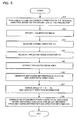
A flowchart of the flow of keystone distortion correction in accordance with this
embodiment is shown in Fig. 5.
-
First of all, the vertical keystone distortion correction section 141 transmits a
vertical keystone distortion correction value corresponding to the inclination of the
projector 10 in the vertical direction, as detected by the inclination sensor 142, to the
resizing section 114. The resizing section 114 resizes the input image signal to perform
a keystone distortion correction in the vertical direction (step S1).
-
The calibration signal generation section 150 generates a calibration signal that
causes the display of a completely white maximum grayscale image, and the image
projection section 190 projects that (step S2).
-
The viewer 40 points the remote controller 20 in the direction perpendicular to
the projection area 30 and presses a normal direction measurement button on the remote
controller 20. In accordance with this action, the direction determination section 240
measures the normal direction n (step S3).
-
The viewer 40 then points the remote controller 20 toward the vicinity of the
center of the projected image 70, which maintaining the horizontal orientation thereof,
and presses a keystone distortion correction button. In accordance with this action, the
direction determination section 240 measures the projected image direction i (step S4).
-
Concomitant with these actions, the area sensor section 210 senses the
projection area 30 and extracts the area of the projected image 70 from the captured
image 60 (step S5).
-
The histogram processing section 230 generates the histogram 80 of the numbers
of pixels in the horizontal direction and the histogram 82 of the numbers of pixels in the
vertical direction, based on the projected image 70, derives the above-described a, b, c,
and d values, and generates the histogram information (step S6).
-
The direction determination section 240 derives the angle = n - i, and
generates the direction information (step S7).
-
The transmitter section 250 of the remote controller 20 transmits the histogram
information and direction information to the projector 10. The receiver section 160 of
the projector 10 receives the histogram information and direction information from the
remote controller 20.
-
The horizontal keystone distortion correction section 143 sends a horizontal
direction keystone distortion correction value, that is based on a correction value from
the 3D-LUT 144 corresponding to the histogram information and direction information,
to the resizing section 114. The resizing section 114 corrects the keystone distortion in
the horizontal direction by correcting the input image signal in such a manner that the
keystone distortion in the horizontal direction is corrected thereby, based on that
correction value (step S8).
-
The above-described procedure makes it possible for the image processing
system that comprises the remote controller 20 to correct keystone distortion from
consideration of the virtual viewpoint position 50, automatically and also appropriately.
-
Note that the hardware described below could be employed as the hardware of
the above-described projector 10.
-
A block diagram of the hardware of the projector 10 in accordance with this
embodiment is shown in Fig. 6.
-
For example, the configuration could be implemented by an A/D converter 930
or the like as the A/D converter section 112; an image processing circuit 970, RAM 950,
and a CPU 910 or the like as the color conversion section 120 and the keystone
distortion correction section 140; a D/A converter 940 or the like as the D/A converter
section 132; and a liquid-crystal panel 920 and a ROM 960 in which is stored liquid-crystal
light valve drivers for driving the liquid-crystal panel 920 as the spatial light
modulator 192.
-
Note that these components can exchange information between themselves over
a system bus 980.
-
The transfer paths between the projector 10 and the remote controller 20 could
be either cables or wireless. Infrared ports or the like could be used for wireless
information exchange or input-output ports or the like could be used for wired
information exchange, between the receiver section 160 of the projector 10 and the
transmitter section 250 of the remote controller 20.
-
The rest of the hardware of the remote controller 20 could be implemented by
using a CCD sensor or the like as the area sensor section 210 and image processing
circuitry as the projected image area extraction section 220 and the histogram
processing section 230.
-
In addition, these components could be implemented in a hardware manner by
circuitry or in a software manner by drivers.
-
The keystone distortion correction section 140 could also be implemented by
reading from an information storage medium 900 a program that causes a computer to
function as the keystone distortion correction section 140, to cause the computer to
function as the keystone distortion correction section 140.
-
The information storage medium 900 could be a CD-ROM, DVD-ROM, ROM,
RAM, or HDD, by way of example, and the method of reading the program therefrom
could be a direct method or an indirect method.
-
Instead of the information storage medium 900, it is also possible to download a
program that implements the above-described functions, from a host device through a
transfer path, in order to implement the above-described functions.
-
As described above, this embodiment makes it possible for the image processing
system to determine the keystone distortion by sensing from the virtual viewpoint
position 50 which is the sensing position. The image processing system can convert the
magnitude of the distortion into numerical values by converting the sensing information
into the histogram 80 of the numbers of pixels in the horizontal direction and the
histogram 82 of the numbers of pixels in the vertical direction. In addition, the image
processing system can determine any relative displacement between the sensing
direction and the projection direction by determining the angle .
-
The image processing system can also correct not only keystone distortion in the
vertical direction, but also keystone distortion in the horizontal direction, both
automatically and appropriately, by correcting the keystone distortion based on
histogram information that represents the distortion circumstances and direction
information that represents the relative displacement between the sensing direction and
the projection direction.
-
The keystone distortion in the horizontal direction varies with the relative
positional relationship between the projector 10 and the projection area 30, whereas the
keystone distortion in the vertical direction is mainly affected by the inclination of the
projector 10.
-
Since the image processing system can therefore use the inclination sensor 142
provided in the projector 10 to correct keystone distortion in the vertical direction and
also use the histogram information that represents the relative positional relationship
between the projector 10 and the projection area 30 to correct keystone distortion in the
horizontal direction, it can correct keystone distortion in both the vertical direction and
the horizontal direction as appropriate.
Second embodiment
-
The description now turns to a second embodiment that corrects keystone
distortion by projecting a rectangular laser beam from the virtual viewpoint position 50
to the projection area 30 and sensing the projection area 30 from a projection position
52. Note that the virtual viewpoint position 50 in this second embodiment is the position
from which the laser beam is projected.
-
A schematic view of the projected image 70 and a laser beam projected image
90 in accordance with the second embodiment is shown in Fig. 7.
-
In this embodiment, a laser beam is projected from the remote controller
operated by the viewer 40 within the projected image 70, in a rectangular form as seen
by the viewer 40.
-
As a result, the captured image 60 comprises the projected image 70 that is a
trapezium ABCD and the laser beam projected image 90 that is a rectangle EFGH
within the trapezium ABCD. Note that the laser beam projected image 90 is preferably
formed within the projected image 70.
-
The projected image 70 is reshaped into a rectangle to correct keystone
distortion, by associating the coordinates of the four comers of the rectangle EFGH with
four conversion coordinates within the spatial light modulator 192 then mapping the
coordinates of the input image into those four conversion coordinates.
-
The description now turns to the functional blocks of the projector 10 and the
remote controller for implementing these functions.
-
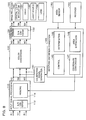
A functional block diagram of the projector 10 in accordance with this
embodiment is shown in Fig. 8. A functional block diagram of a remote controller 21 in
accordance with this embodiment is shown in Fig. 9.
-
The remote controller 21 of this embodiment comprises a laser beam projection
section 280 that functions as a light projection means, an operating section 270, and a
transmitter section 260 that transmits signals such as an operation-start signal to the
projector 10.
-
The projector 10 of this embodiment has a similar configuration to that of the
projector 10 of Fig. 3, described as the first embodiment, except that it differs from the
projector 10 of Fig. 3 in the functions of the keystone distortion correction section 140
and in the provision of an area sensor section 180 that functions as sensing means.
-
The keystone distortion correction section 140 of this embodiment comprises a
control section 145, a determination section 146, a coordinate conversion section 147,
and an area extraction section 148 that extracts the coordinates of the four comers of the
projected image 70 in the captured image 60 and the coordinates of the four comers of
the laser beam projected image 90 in the captured image 60, based on sensing
information.
-
The area sensor section 180 is provided with the projector 10 of Fig. 1, for
sensing the projection area 30 from the projection position 52.
-
Note that the brightness and color of the projected image 70 differ from the
brightness and color of the laser beam projected image 90. It is therefore possible for the
area extraction section 148 to distinguish between the laser beam projected image 90
and the projected image 70 within the captured image 60, by demarcating in accordance
with brightness or color.
-
The description now turns to the flow of processing with these components.
-
A flowchart of the flow of processing by the remote controller 20 in accordance
with this embodiment is shown in Fig. 10.
-
First of all, the description relates to the flow of processing by the remote
controller 21.
-
The viewer faces the projection area 30 and presses a distortion correction
button of the remote controller 21. This makes the operating section 270 output a
control signal to the transmitter section 260, and the transmitter section 260 transmits a
start signal (meaning start the keystone distortion correction) to the projector 10 (step
S11).
-
The viewer 40 presses a projection button of the remote controller 21 when a
patch (calibration image) is projected by the projector 10 (step S12). This makes the
operating section 270 output a control signal to the laser beam projection section 280 to
make it output a laser beam.
-
The laser beam projection section 280 projects a rectangular laser beam based on
the control signal (step S13).
-
The description now concerns the flow of processing by the projector 10.
-
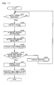
A flowchart of the flow of processing by the projector 10 in accordance with this
embodiment is shown in Fig. 11.
-
The determination section 146 determines whether or not the receiver section
160 has received a keystone distortion correction start signal from the remote controller
21 (step S21).
-
If it has received the start signal, the image projection section 190 projects a
completely-white patch, based on a calibration signal by the calibration signal
generation section 150 (step S22).
-
Note that when the patch is projected, the viewer 40 adjusts the position and
direction of the remote controller 21 in such a manner that the laser beam is displayed
as a rectangle within the projected image 70 of the patch.
-
The area sensor section 180 senses the projection area 30 in which the laser
beam projected image 90 and the projected image 70 are displayed, and generates
sensing information (step S23).
-
The area extraction section 148 extracts the projected image area (the
coordinates of the sensed area defined by the four comers ABCD of the projected image
70) that has brightnesses within the range of the projected light, based on the sensing
information (step S24).
-
Concomitant therewith, the area extraction section 148 extracts the laser frame
area (the coordinates of the sensed area defined by the four comers EFGH of the laser
beam projected image 90) that has brightnesses within the range of the laser beam,
based on the sensing information (step S25).
-
The determination section 146 determines whether or not the laser frame area is
within the projected image area, based on the coordinates extracted by the area
extraction section 148 (step S26).
-
If the laser frame area is within the projected image area, the coordinate
conversion section 147 converts the coordinates EFGH of the laser frame area into
coordinates E'F'G'H' in the processing system of the spatial light modulator 192 of the
image projection section 190 (step S27).
-
The resizing section 114 maps the input image signal into an area formed by the
coordinates E'F'G'H'.
-
The image projection section 190 projects an image based on the thus-mapped
image information (step S29).
-
Note that if the laser frame area is not within the projected image area, the
control section 145 outputs a control signal to the calibration signal generation section
150, so as to cause the projection of a message image prompting the viewer 40 to
project the laser frame area into the projected image area.
-
The calibration signal generation section 150 generates the signal for that
message image and the image projection section 190 displays the message based on the
signal for that message image (step S28).
-
In this manner, this embodiment makes it possible to determine the coordinates
of a rectangle of light created by light of a rectangular shape projected into the
projection area 30 in a state in which there is no distortion when seen from the virtual
viewpoint position 50, by sensing from the projection position 52.
-
In other words, the coordinates of the rectangle of light enable the capture of the
coordinates of a distortion-free image, and a distortion-free image can be projected
during the projection of images by mapping the coordinates of the input image onto
those coordinates.
-
This makes it possible to correct keystone distortion not only in the vertical
direction but also in the horizontal direction, both automatically and appropriately.
-
In comparison with the first embodiment, there is no need for the 3D-LUT 144,
enabling a reduction in necessary storage capacity.
Modifications
-
The present invention was described above with reference to preferred
embodiments thereof but it should be obvious to those skilled in the art that the
application of the present invention is not limited to the above-described embodiments.
-
For example, an input image signal is mapped into a laser frame area in the
second embodiment, but it is equally possible to use laser beam information only in the
obtaining of distortion information. As an example thereof, it is possible to obtain an
image such that keystone distortion is corrected within suitable dimensions (such as the
largest possible dimensions), irrespective of the dimensions of the laser frame, by using
the system of the second embodiment to project and sense a laser frame, determining
distortion of the laser frame of the sensed image by the histogram processing section of
the first embodiment (in this case, within the projector 10), and resizing the input image
in accordance with the distortion circumstances.
-
Furthermore, the viewer 40 is assumed to be placed facing the projection area 30
in the second embodiment, but the configuration could be such that the direction
determination section 240 of the remote controller 20 of the first embodiment is
provided in the remote controller 21 of the second embodiment, and the histogram
processing section of the remote controller 20 of the first embodiment and the 3D-LUT
of the projector 10 of the first embodiment are provided in the projector 10 of the
second embodiment. In addition, the necessity of positioning the viewer 40 facing the
projection area 30 can be removed by having the projector 10 determine the direction
and laser beam distortion information, to perform keystone distortion correction.
-
In the second embodiment, the laser beam was described as seeming to be
rectangular, by way of example, but it could equally well be another shape such as
square or circular.
-
Furthermore, a laser beam was used in the second embodiment, but any light
that can be distinguished from the projected image 70 can be used therefore, such as
infrared light.
-
In the first embodiment, the inclination sensor 142 is used in the correction of
the keystone distortion in the vertical direction, but keystone distortion in both the
vertical and horizontal directions could be corrected on the basis of the histogram
information and direction information alone, without using the inclination sensor 142.
-
In addition, if the lens 198 and the area sensor section 210 are provided with a
zoom function, the projector 10 could correct keystone distortion by obtaining zoom-related
information (such as numerical values that express the state at the furthest
distance as 0 and the state at the widest angle as 1).
-
This enables automatic and also appropriate keystone distortion correction when
using either the long-distance function or the wide-angle function.
-
In the first embodiment, the remote controller is used to measure the projected
image direction i in the vicinity of the center of the projected image 70 and sense the
projection area 30, in the processing of steps S4 and S5, but the following processing
could be used to ensure that the remote controller is directed reliably toward the center
of the projected image 70.
-
In other words, the configuration could be such that the projector 10 displays a
predetermined mark (such as an "X") at the center of the projected image 70, the user
uses a laser pointing function of the remote controller 20 to press the keystone distortion
correction button while superimposing a laser beam on that predetermined mark, and
the remote controller 20 measures the projected image direction i and senses the
projection area 30. This makes it possible for the image processing system to direct the
remote controller more accurately towards the vicinity of the center of the projected
image 70.
-
In the above-described embodiments, the calibration patch was described as
being a completely-white image, but it is not limited to being completely white and thus
various other calibration images could be used therefore.
-
The configuration of the image processing system and the distribution of
functions between the projector 10 and the remote controllers 20 and 21 are also not
limited to those of the above-described embodiments. The functions of the projected
image area extraction section 220 and the histogram processing section 230 of the first
embodiment could be provided in the projector 10 of the first embodiment, by way of
example. Similarly, the function of the horizontal keystone distortion correction section
143 of the projector 10 of the first embodiment could be provided in the remote
controller 20. Furthermore, the function of the keystone distortion correction section
140 of the second embodiment could be provided in the remote controller 21.
-
In addition, the virtual viewpoint position 50 and the projection position 52 are
not limited to those shown in Fig. 1.
-
In the above-described embodiments, the remote controllers 20 and 21 were
used as portable devices, but other portable devices such as handy terminals, PDAs, or
mobile phones could equally well be used therefore.
-
The embodiments described above related to a liquid-crystal projector as the
image display device, but they can also be applied to a projector using a digital
micromirror device (DMD), by way of example. Note that DMD is a trademark
registered to Texas Instruments Inc. of the USA.
-
Note that the functions of the above-described projector 10 could be
implemented by the projector alone, by way of example, or they could be implemented
by distributing them between a plurality of processing devices (such as between the
projector and a PC).