EP1431088A2 - Vehicular air-conditioner and method of controlling the same - Google Patents
Vehicular air-conditioner and method of controlling the same Download PDFInfo
- Publication number
- EP1431088A2 EP1431088A2 EP03029477A EP03029477A EP1431088A2 EP 1431088 A2 EP1431088 A2 EP 1431088A2 EP 03029477 A EP03029477 A EP 03029477A EP 03029477 A EP03029477 A EP 03029477A EP 1431088 A2 EP1431088 A2 EP 1431088A2
- Authority
- EP
- European Patent Office
- Prior art keywords
- vehicle
- compressor
- conditioner
- braking condition
- condition
- Prior art date
- Legal status (The legal status is an assumption and is not a legal conclusion. Google has not performed a legal analysis and makes no representation as to the accuracy of the status listed.)
- Granted
Links
Images


Classifications
-
- B—PERFORMING OPERATIONS; TRANSPORTING
- B60—VEHICLES IN GENERAL
- B60H—ARRANGEMENTS OF HEATING, COOLING, VENTILATING OR OTHER AIR-TREATING DEVICES SPECIALLY ADAPTED FOR PASSENGER OR GOODS SPACES OF VEHICLES
- B60H1/00—Heating, cooling or ventilating [HVAC] devices
- B60H1/32—Cooling devices
- B60H1/3204—Cooling devices using compression
- B60H1/3205—Control means therefor
- B60H1/322—Control means therefor for improving the stop or idling operation of the engine
-
- B—PERFORMING OPERATIONS; TRANSPORTING
- B60—VEHICLES IN GENERAL
- B60H—ARRANGEMENTS OF HEATING, COOLING, VENTILATING OR OTHER AIR-TREATING DEVICES SPECIALLY ADAPTED FOR PASSENGER OR GOODS SPACES OF VEHICLES
- B60H1/00—Heating, cooling or ventilating [HVAC] devices
- B60H1/32—Cooling devices
- B60H2001/3236—Cooling devices information from a variable is obtained
- B60H2001/3266—Cooling devices information from a variable is obtained related to the operation of the vehicle
-
- B—PERFORMING OPERATIONS; TRANSPORTING
- B60—VEHICLES IN GENERAL
- B60H—ARRANGEMENTS OF HEATING, COOLING, VENTILATING OR OTHER AIR-TREATING DEVICES SPECIALLY ADAPTED FOR PASSENGER OR GOODS SPACES OF VEHICLES
- B60H1/00—Heating, cooling or ventilating [HVAC] devices
- B60H1/32—Cooling devices
- B60H2001/3269—Cooling devices output of a control signal
- B60H2001/327—Cooling devices output of a control signal related to a compressing unit
- B60H2001/3275—Cooling devices output of a control signal related to a compressing unit to control the volume of a compressor
Definitions
- the present invention relates to a vehicular air-conditioner which adjusts temperature environment of a vehicle interior.
- a vehicular air-conditioner sends conditioned air whose temperature adjustment has been performed to the vehicle interior.
- Japanese Patent Application Laid-open No. 2001-105846A discloses that elevating of a cooling performance of a heat exchanger for cooling during vehicle deceleration recovers deceleration energy of a vehicle without giving uncomfortable feeling to a vehicle occupant, thus advantageously saving fuel consumption. According to this, a vehicle occupant great feels more uncomfortable, as a blow-off temperature of conditioned air into the vehicle interior varies greater.
- the limitation of variation range for a vehicle occupant not to feel uncomfortable is varied according to a blow-off air-flow rate into the vehicle interior.
- a target evaporator has a decrement of blow-off temperature during vehicle deceleration.
- the decrement of the blow-off temperature is set to become smaller, as a target air-flow rate becomes from Low towards High.
- the decrement becomes great when an air blow rate is small, thus advantageously saving fuel consumption without giving uncomfortable feeling to a vehicle occupant.
- a compressor in an air-conditioner is operating even during vehicle deceleration. Even when a throttle interlocked to an accelerator pedal is in a full closed state, an idle speed control valve (hereinafter, "ISC valve") which controls engine revolutions during idling operation is opened or closed. The opening or closing permits an intake air volume to be increased, thus increasing the engine revolutions. This permits an engine to be controlled not to stop due to a load of the compressor.
- ISC valve idle speed control valve
- a passenger vehicle employs a brake apparatus.
- the brake apparatus utilizes a differential pressure between the atmosphere pressure and a boost pressure of the engine to amplify a pressing force of a driver on a brake pedal until the force reaches a braking force sufficient to stop a vehicle during running thereof.
- An object of the present invention is to provide a vehicular air-conditioner which reduces a load on an engine during vehicle deceleration.
- a first aspect of the invention is directed to a vehicular air-conditioner.
- the air-conditioner includes a compressor to be driven by an engine.
- the air-conditioner includes a controller configured to reduce a load on the compressor in response to a braking condition of a vehicle.
- the compressor may include a clutch configured to transmit torque from the engine to the compressor.
- the controller is configured to disengage the clutch to stop the compressor under the braking condition of the vehicle.
- the compressor may have a variable displacement compressor.
- the controller is configured to reduce a coolant in discharge rate from the compressor under the braking condition of the vehicle.
- the controller may be configured to stop reducing of a load on the compressor in response to a non-braking condition of the vehicle.
- the controller may include a first controller configured to control the engine and to determine the braking condition of the vehicle.
- the controller may include a second controller configured to reduce a load on the compressor in response to the braking condition of the vehicle.
- the braking condition may include a first condition of a predetermined vehicle speed or more or predetermined engine revolutions or more.
- the braking condition may include a second condition of pressing-down of a brake pedal, lighting of a tail lamp or increase of a brake hydraulic pressure.
- the braking condition may include a third condition of release of an accelerator pedal.
- a second aspect of the invention is directed to a method of controlling a vehicular air-conditioner.
- the control method includes the step of determining a braking condition of a vehicle.
- the control method includes the step of reducing a load on a compressor in response to the braking condition of the vehicle.
- the determining of the braking condition of the vehicle may include the step of determining a predetermined vehicle speed or more or predetermined engine revolutions or more.
- the determining of the braking condition may include the step of determining pressing-down of a brake pedal, lighting of a tail lamp or increase of a brake hydraulic pressure.
- the determining of the braking condition may include the step of determining release of an accelerator pedal.
- a vehicular air-conditioner 1 utilizes an engine driving force as a power source, as indicated in Fig. 1.
- the air- conditioner 1 includes a variable displacement compressor 10 which can change a discharge rate of coolant according to a set temperature in a vehicle interior.
- the air-conditioner 1 includes an electromagnetic control valve (ECV) 11.
- ECV electromagnetic control valve
- the air-conditioner 1 includes a clutch 14 which transmits torque from an engine to the compressor.
- the air-conditioner 1 includes an air-conditioner computer (A/C computer) 12 which controls the compressor 10 under an operating condition.
- the A/C computer 12 is electrically connected to the ECV 11 and the clutch 14.
- the air-conditioner 1 includes a Tint sensor 13 which measures an air temperature to be introduced into the air-conditioner 1.
- the compressor 10 compresses or discharges coolant supplied inside of a cylinder when a piston reciprocates inside the cylinder provided inside a main body of the compressor. Variation of an internal pressure in a crank chamber can cause a stroke amount of the reciprocating piston to change a discharge rate of the coolant.
- the ECV 11 introduces a high pressure in a discharge chamber into the crank chamber and is controlled by an external signal.
- the A/C computer 12 calculates and determines a target evaporator passing-through air temperature on the basis of a vehicle interior temperature sensor, an outside air temperature sensor output, a solar radiation sensor, and respective set values (blower, temperature).
- the A/C computer 12 outputs a signal to the ECV 11 so as to establish the target value.
- the A/C computer 12 transmits or receives signals to or from an engine computer 51 which performs engine control by a vehicle body equipment 50.
- the engine computer 51 has signals to be inputted from various sensors. That is, the engine computer receives sensor signals about a brake pedal 52, a tail lamp 53, a brake hydraulic pressure 54, engine revolutions 55, a boost pressure 56, a vehicle speed 57 and an accelerator 58 in order to determine a running condition of a vehicle.
- the A/C computer 12 acquires sensor signals through the engine computer 51.
- the A/C computer 12 determines "braking condition" of a vehicle on the basis of these sensor signals to control the ECV 11.
- Such a constitution may be employed that the engine computer 51 determines the "braking condition" of the vehicle on the basis of the sensor signals to transmit the results to the A/C computer 12.
- control starts (S1).
- the engine computer 51 transmits sensor signals to the A/C computer 12.
- the A/C computer 12 determines whether or not the vehicle is under a braking condition on the basis of the sensor signals (S2).
- the A/C computer 12 controls the ECV 11 according to a normal control (S3).
- the A/C computer 12 confirms an upper limit value of the Tint (S4) to perform a load reduction control to the ECV 11 (S5).
- the "braking condition" in step S2 is determined according to an AND with the following first, second and third conditions.
- the first condition is a vehicle speed equal to or more than X (km/h) or engine revolutions equal to or more than Y (rpm).
- the second condition is a pressing-down of the brake pedal 52, a lighting of the tail lamp 53 or increase of the brake hydraulic pressure 54.
- the third condition is a state that the accelerator pedal has not been pressed, or release of the accelerator pedal.
- the Tint sensor 13 detects an air temperature introduced into the air-conditioner 1 (S31).
- the A/C computer 12 calculates a difference between an output temperature of the Tint sensor 13 and a set target temperature of a vehicle interior.
- the A/C computer 12 calculates DUTY ratio of PWM control from the temperature difference (S32).
- the A/C computer 12 outputs the DUTY ratio to the ECV 11 to control opening or closing of the ECV11 (S33).
- the A/C computer 12 determines whether or not a temperature Tint of air introduced into the air-conditioner 1 exceeds a predetermined upper limit value (S4).
- the A/C computer 12 performs the normal control S3.
- the control of the A/C computer 12 performs the load reduction control S5.
- the A/C computer 12 under the load reduction control S5 outputs a required DUTY ratio to the EVC 11 (S51). That is, reducing of the DUTY ratio of the ECV11 reduces an opening degree of the ECV11. This establishes the stroke amount of the compressor 10 at substantially zero, thus reducing an engine load.
- the A/C computer 12 may disconnect the clutch 14 to stop the compressor 10. Further, the A/C computer 12 may reduce a discharge rate of coolant of the compressor 10.
- boost pressures in the air-conditioner 1 and a comparative air-conditioner during operation is described.
- a vehicle is under an accelerating condition before a time t1.
- the vehicle is under a constant running condition between times t1 and t2.
- the vehicle is under a braking condition between times t2 and t3.
- the vehicle is put in an idling condition on time t3 and thereafter.
- the air-conditioner 1 is put in an operating condition for the whole period of time.
- the air-conditioner 1 has small variation of the boost pressure B during the braking condition of the vehicle (times t2 to t3) as compared with the comparative air-conditioner. Accordingly, the boost pressure due to the air-conditioner 1 is sufficiently lowered as compared with that in the comparative air-conditioner.
- the opening degree of the ISC valve can be reduced in the full closed state of the throttle. Therefore, decrease in the intake air volume into the engine allows the boost pressure is lowered.
- a brake apparatus 70 is used in a passenger vehicle.
- the brake apparatus 70 has a brake pedal 52 to be pressed down by a driver.
- the brake apparatus 70 includes a master back 71 boosting a pressing force of the brake pedal 52.
- the brake apparatus 70 includes a master cylinder 72 which converts the boosted pressing force to a hydraulic pressure.
- the brake apparatus 70 includes hydraulic pressure pipes 73 which transfer the converted hydraulic pressure to respective wheels.
- the brake apparatus 70 has brake discs 74 to rotate together with the respective wheels. According to the brake apparatus 70, pressing-down of the brake pedal 52 performed by a driver permits a piston in the master cylinder 72 to push brake pads against the brake discs 74. Frictions between the brake pads and the brake discs 74 obtains a braking force.
- the master back 71 has an internal space separated into an atmospheric pressure chamber 75 and a boost pressure chamber 76.
- the master back 71 includes a piston 77 provided slidably so as to change volumes of the atmospheric pressure chamber 75 and the boost pressure chamber 76.
- the master back 71 includes a boost pressure pipe 78 for supplying a boost pressure to the boost pressure chamber 76.
- the master back 71 includes an atmospheric pressure pipe 80 provided with an atmospheric pressure ECV79 for controlling an air volume introduced into the atmospheric pressure chamber 75.
- the master back 71 opens the atmospheric pressure ECV 79 according to the pressing force. Thereby, the piston 77 is pulled from the atmospheric pressure chamber 75 towards the boost pressure chamber 76 so that the pressing force is amplified. The amplified pressing force is transferred to the master cylinder 72.
- the control apparatus of the compressor determines the current state as the "braking condition" to perform the load reduction control.
- the control reduces an intake air volume required for decreasing the engine load to maintain the engine revolutions.
- the opening degree of the ISC valve can be narrowed, which lowers the boost pressure of the engine in the vicinity of the stopped condition of the air-conditioner. Accordingly, a stable braking performance is obtained even while the interior air conditioning is being performed.
- the load reduction control is terminated. Thereby, the load reduction control is performed during the braking condition of the vehicle, which reduces the engine load without giving uncomfortable feeling to a vehicle occupant.
- This control permits the boost pressure to be lowered down to about the stopped condition of the air-conditioner for vehicle.
- the engine brake acts in the identical manner to the stopped condition of the vehicular air-conditioner, thus achieving a further strong braking force.
- the compressor 10 is employed to change the stroke amount of the piston, thus reducing the engine load.
- a compressor with a clutch 14 for transmission of torque from the engine may be employed to disconnect the clutch 14 during braking condition of the vehicle to stop operation of the compressor.
Abstract
Description
- This application is based upon and claims the benefit of priority from Japanese Patent Application No. 2002-368700 filed on December 19, 2002; the entire contents of which are incorporated herein by reference.
- The present invention relates to a vehicular air-conditioner which adjusts temperature environment of a vehicle interior.
- In order to improve temperature environment of a vehicle interior, a vehicular air-conditioner sends conditioned air whose temperature adjustment has been performed to the vehicle interior. Japanese Patent Application Laid-open No. 2001-105846A discloses that elevating of a cooling performance of a heat exchanger for cooling during vehicle deceleration recovers deceleration energy of a vehicle without giving uncomfortable feeling to a vehicle occupant, thus advantageously saving fuel consumption. According to this, a vehicle occupant great feels more uncomfortable, as a blow-off temperature of conditioned air into the vehicle interior varies greater. On the other hand, the limitation of variation range for a vehicle occupant not to feel uncomfortable is varied according to a blow-off air-flow rate into the vehicle interior. In view of this fact, a target evaporator has a decrement of blow-off temperature during vehicle deceleration. The decrement of the blow-off temperature is set to become smaller, as a target air-flow rate becomes from Low towards High. Thereby, the decrement becomes great when an air blow rate is small, thus advantageously saving fuel consumption without giving uncomfortable feeling to a vehicle occupant.
- A compressor in an air-conditioner is operating even during vehicle deceleration. Even when a throttle interlocked to an accelerator pedal is in a full closed state, an idle speed control valve (hereinafter, "ISC valve") which controls engine revolutions during idling operation is opened or closed. The opening or closing permits an intake air volume to be increased, thus increasing the engine revolutions. This permits an engine to be controlled not to stop due to a load of the compressor.
- A passenger vehicle employs a brake apparatus. The brake apparatus utilizes a differential pressure between the atmosphere pressure and a boost pressure of the engine to amplify a pressing force of a driver on a brake pedal until the force reaches a braking force sufficient to stop a vehicle during running thereof.
- Accordingly, when the throttle is fully closed in a state that an air-conditioner is operating, an intake air volume into the engine is increased by the ISC valve for operating the compressor. The boost pressure is maintained due to the increase until the throttle is fully closed in a state that the air-conditioner has stopped. That is, a differential pressure between the atmospheric pressure and the boost pressure is reduced, deteriorating engine braking effect. Thus, there is a possibility that the reduction of the differential pressure deteriorates a braking performance in dependence on the structure of the brake apparatus.
- An object of the present invention is to provide a vehicular air-conditioner which reduces a load on an engine during vehicle deceleration.
- A first aspect of the invention is directed to a vehicular air-conditioner. The air-conditioner includes a compressor to be driven by an engine. The air-conditioner includes a controller configured to reduce a load on the compressor in response to a braking condition of a vehicle.
- The compressor may include a clutch configured to transmit torque from the engine to the compressor. The controller is configured to disengage the clutch to stop the compressor under the braking condition of the vehicle.
- The compressor may have a variable displacement compressor.
- The controller is configured to reduce a coolant in discharge rate from the compressor under the braking condition of the vehicle.
- The controller may be configured to stop reducing of a load on the compressor in response to a non-braking condition of the vehicle.
- The controller may include a first controller configured to control the engine and to determine the braking condition of the vehicle. The controller may include a second controller configured to reduce a load on the compressor in response to the braking condition of the vehicle.
- The braking condition may include a first condition of a predetermined vehicle speed or more or predetermined engine revolutions or more. The braking condition may include a second condition of pressing-down of a brake pedal, lighting of a tail lamp or increase of a brake hydraulic pressure. The braking condition may include a third condition of release of an accelerator pedal.
- A second aspect of the invention is directed to a method of controlling a vehicular air-conditioner. The control method includes the step of determining a braking condition of a vehicle. The control method includes the step of reducing a load on a compressor in response to the braking condition of the vehicle.
- The determining of the braking condition of the vehicle may include the step of determining a predetermined vehicle speed or more or predetermined engine revolutions or more. The determining of the braking condition may include the step of determining pressing-down of a brake pedal, lighting of a tail lamp or increase of a brake hydraulic pressure. The determining of the braking condition may include the step of determining release of an accelerator pedal.
-
- Fig. 1 is a block diagram illustrating a vehicular air-conditioner of an embodiment according to the present invention;
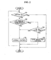
- Fig. 2 is a flowchart illustrating control of the air-conditioner indicated in Fig. 1;
- Fig. 3 is a flowchart illustrating a normal control in an A/C computer;
- Fig. 4 is a flowchart illustrating a load reduction control of a vehicle braking condition in the A/C computer;
- Fig. 5 is a diagram illustrating a logic circuit about conditions of the braking condition;
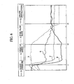
- Fig. 6 is a graph illustrating variation of a boost pressure during baking, while the air condition indicated in Fig. 1 is operating:
- Fig. 7 is a graph illustrating variation of the boost pressure during baking, while a comparative air-conditioner is operating; and
- Fig. 8 is a schematic diagram illustrating a structure of a brake apparatus.
-
- Embodiments of the present invention are described with reference to the drawings.
- A vehicular air-
conditioner 1 according to an embodiment utilizes an engine driving force as a power source, as indicated in Fig. 1. The air-conditioner 1 includes avariable displacement compressor 10 which can change a discharge rate of coolant according to a set temperature in a vehicle interior. The air-conditioner 1 includes an electromagnetic control valve (ECV) 11. The air-conditioner 1 includes aclutch 14 which transmits torque from an engine to the compressor. The air-conditioner 1 includes an air-conditioner computer (A/C computer) 12 which controls thecompressor 10 under an operating condition. The A/C computer 12 is electrically connected to theECV 11 and theclutch 14. The air-conditioner 1 includes aTint sensor 13 which measures an air temperature to be introduced into the air-conditioner 1. - The
compressor 10 compresses or discharges coolant supplied inside of a cylinder when a piston reciprocates inside the cylinder provided inside a main body of the compressor. Variation of an internal pressure in a crank chamber can cause a stroke amount of the reciprocating piston to change a discharge rate of the coolant. - The ECV 11 introduces a high pressure in a discharge chamber into the crank chamber and is controlled by an external signal.
- The A/
C computer 12 calculates and determines a target evaporator passing-through air temperature on the basis of a vehicle interior temperature sensor, an outside air temperature sensor output, a solar radiation sensor, and respective set values (blower, temperature). The A/C computer 12 outputs a signal to theECV 11 so as to establish the target value. - The A/
C computer 12 transmits or receives signals to or from anengine computer 51 which performs engine control by avehicle body equipment 50. Theengine computer 51 has signals to be inputted from various sensors. That is, the engine computer receives sensor signals about abrake pedal 52, atail lamp 53, a brakehydraulic pressure 54,engine revolutions 55, aboost pressure 56, a vehicle speed 57 and anaccelerator 58 in order to determine a running condition of a vehicle. - The A/
C computer 12 acquires sensor signals through theengine computer 51. The A/C computer 12 determines "braking condition" of a vehicle on the basis of these sensor signals to control theECV 11. Such a constitution may be employed that theengine computer 51 determines the "braking condition" of the vehicle on the basis of the sensor signals to transmit the results to the A/C computer 12. - One example of a control method of the air-
conditioner 1 is described with reference to Fig. 2. - First, when a switch of the air-
conditioner 1 is turned on, control starts (S1). Next, theengine computer 51 transmits sensor signals to the A/C computer 12. The A/C computer 12 determines whether or not the vehicle is under a braking condition on the basis of the sensor signals (S2). - In case of the vehicle under a "non-braking conditian", the A/
C computer 12 controls theECV 11 according to a normal control (S3). On the other hand, when the vehicle is under a braking condition during running, the A/C computer 12 confirms an upper limit value of the Tint (S4) to perform a load reduction control to the ECV 11 (S5). - With reference to Fig. 5, the "braking condition" in step S2 is determined according to an AND with the following first, second and third conditions. The first condition is a vehicle speed equal to or more than X (km/h) or engine revolutions equal to or more than Y (rpm). The second condition is a pressing-down of the
brake pedal 52, a lighting of thetail lamp 53 or increase of the brakehydraulic pressure 54. The third condition is a state that the accelerator pedal has not been pressed, or release of the accelerator pedal. - Control of the steps S2, S3, S4 and S5 is repeated until the switch in the air-
conditioner 1 is turned off. - With reference to a flowchart indicated in Fig. 3, the normal control S3 under the "non-braking condition" is described.
- The
Tint sensor 13 detects an air temperature introduced into the air-conditioner 1 (S31). - Next, the A/
C computer 12 calculates a difference between an output temperature of theTint sensor 13 and a set target temperature of a vehicle interior. The A/C computer 12 calculates DUTY ratio of PWM control from the temperature difference (S32). The A/C computer 12 outputs the DUTY ratio to theECV 11 to control opening or closing of the ECV11 (S33). - A control method in the "braking condition" is described on the basis of a flowchart indicated in Figs. 2 and 4.
- In Fig. 2, the A/
C computer 12 determines whether or not a temperature Tint of air introduced into the air-conditioner 1 exceeds a predetermined upper limit value (S4). - Here, there is a possibility that the Tint over the upper limit value increases a vehicle interior temperature to give uncomfortable feeling to a vehicle occupant. Accordingly, the A/
C computer 12 performs the normal control S3. On the other hand, when the Tint is equal to or less than the upper limit value, the control of the A/C computer 12 performs the load reduction control S5. - In Fig. 4, the A/
C computer 12 under the load reduction control S5 outputs a required DUTY ratio to the EVC 11 (S51). That is, reducing of the DUTY ratio of the ECV11 reduces an opening degree of the ECV11. This establishes the stroke amount of thecompressor 10 at substantially zero, thus reducing an engine load. On the other hand, the A/C computer 12 may disconnect the clutch 14 to stop thecompressor 10. Further, the A/C computer 12 may reduce a discharge rate of coolant of thecompressor 10. - With reference to Figs. 6 and 7, variations of boost pressures in the air-
conditioner 1 and a comparative air-conditioner during operation is described. A vehicle is under an accelerating condition before a time t1. The vehicle is under a constant running condition between times t1 and t2. The vehicle is under a braking condition between times t2 and t3. The vehicle is put in an idling condition on time t3 and thereafter. The air-conditioner 1 is put in an operating condition for the whole period of time. - From comparison of Figs. 6 and 7 to each other, the air-
conditioner 1 has small variation of the boost pressure B during the braking condition of the vehicle (times t2 to t3) as compared with the comparative air-conditioner. Accordingly, the boost pressure due to the air-conditioner 1 is sufficiently lowered as compared with that in the comparative air-conditioner. - This causes the load reduction control to reduce the stroke amount of the
compressor 1 during the braking condition of the vehicle, thus reducing an engine load. Thereby, the opening degree of the ISC valve can be reduced in the full closed state of the throttle. Therefore, decrease in the intake air volume into the engine allows the boost pressure is lowered. - With reference to Fig. 8, a
brake apparatus 70 is used in a passenger vehicle. Thebrake apparatus 70 has abrake pedal 52 to be pressed down by a driver. Thebrake apparatus 70 includes a master back 71 boosting a pressing force of thebrake pedal 52. Thebrake apparatus 70 includes amaster cylinder 72 which converts the boosted pressing force to a hydraulic pressure. Thebrake apparatus 70 includeshydraulic pressure pipes 73 which transfer the converted hydraulic pressure to respective wheels. Thebrake apparatus 70 hasbrake discs 74 to rotate together with the respective wheels. According to thebrake apparatus 70, pressing-down of thebrake pedal 52 performed by a driver permits a piston in themaster cylinder 72 to push brake pads against thebrake discs 74. Frictions between the brake pads and thebrake discs 74 obtains a braking force. - The master back 71 has an internal space separated into an
atmospheric pressure chamber 75 and aboost pressure chamber 76. The master back 71 includes apiston 77 provided slidably so as to change volumes of theatmospheric pressure chamber 75 and theboost pressure chamber 76. The master back 71 includes aboost pressure pipe 78 for supplying a boost pressure to theboost pressure chamber 76. The master back 71 includes anatmospheric pressure pipe 80 provided with an atmospheric pressure ECV79 for controlling an air volume introduced into theatmospheric pressure chamber 75. - When the
brake pedal 52 is pressed down, the master back 71 opens theatmospheric pressure ECV 79 according to the pressing force. Thereby, thepiston 77 is pulled from theatmospheric pressure chamber 75 towards theboost pressure chamber 76 so that the pressing force is amplified. The amplified pressing force is transferred to themaster cylinder 72. - Accordingly, by causing the boost pressure during braking condition to approach to the boost pressure put in a state where the air-conditioner is not operating. This enlarges the amplifying ratio of the pressing force conducted by the master back 71, thus stabilizing the braking force.
- As described above, the control apparatus of the compressor determines the current state as the "braking condition" to perform the load reduction control. The control reduces an intake air volume required for decreasing the engine load to maintain the engine revolutions. Thereby, the opening degree of the ISC valve can be narrowed, which lowers the boost pressure of the engine in the vicinity of the stopped condition of the air-conditioner. Accordingly, a stable braking performance is obtained even while the interior air conditioning is being performed.
- In case that the control apparatus determines that the vehicle is under the 'non-braking condition", the load reduction control is terminated. Thereby, the load reduction control is performed during the braking condition of the vehicle, which reduces the engine load without giving uncomfortable feeling to a vehicle occupant.
- This control permits the boost pressure to be lowered down to about the stopped condition of the air-conditioner for vehicle. Thereby, the engine brake acts in the identical manner to the stopped condition of the vehicular air-conditioner, thus achieving a further strong braking force.
- In this embodiment, the
compressor 10 is employed to change the stroke amount of the piston, thus reducing the engine load. On the other hand, a compressor with a clutch 14 for transmission of torque from the engine may be employed to disconnect the clutch 14 during braking condition of the vehicle to stop operation of the compressor. Thereby, a similarly advantageous effect can be obtained even if the engine load is reduced. - Although the invention has been described above by reference to certain embodiments of the invention, the invention is not limited to the embodiments described above. Modifications and variations of the embodiments described above will occur to those skilled in the art, in light of the above teachings. The scope of the invention is defined with reference to the following claims.
Claims (8)
- A vehicular air-conditioner comprising:a compressor to be driven by an engine;a controller configured to reduce a load on the compressor in response to a braking condition of a vehicle.
- The vehicular air-conditioner according to the claim 1,
wherein the compressor includes a clutch configured to transmit torque from the engine to the compressor,
wherein the controller is configured to disengage the clutch to stop the compressor under the braking condition of the vehicle. - The vehicular air-conditioner according to claim 1,
wherein the compressor has a variable displacement compressor,
wherein the controller is configured to reduce a coolant in discharge rate from the compressor under the braking condition of the vehicle. - The vehicular air-conditioner according to claim 1.
wherein the controller is configured to stop reducing of a load on the compressor in response to a non-braking condition of the vehicle. - The vehicular air-conditioner according to claim 1,
wherein the controller includes,
a first controller configured to control the engine and to determine the braking condition of the vehicle, and
a second controller configured to reduce a load on the compressor in response to the braking condition of the vehicle. - The vehicular air-conditioner according to claim 1,
wherein the braking condition includes,
a first condition of a predetermined vehicle speed or more or predetermined engine revolutions or more;
a second condition of pressing-down of a brake pedal, lighting of a tail lamp or increase of a brake hydraulic pressure; and
a third condition of release of an accelerator pedal. - A method of controlling a vehicular air-conditioner, comprising;
determining a braking condition of a vehicle; and
reducing a load on a compressor in response to the braking condition of the vehicle. - The method of claim 7,
wherein the determining of the braking condition of the vehicle includes,
determining a predetermined vehicle speed or more or predetermined engine revolutions or more;
determining pressing-down of a brake pedal, lighting of a tail lamp or increase of a brake hydraulic pressure; and
determining release of an accelerator pedal.
Applications Claiming Priority (2)
| Application Number | Priority Date | Filing Date | Title |
|---|---|---|---|
| JP2002368700A JP4083561B2 (en) | 2002-12-19 | 2002-12-19 | Air conditioner for vehicles |
| JP2002368700 | 2002-12-19 |
Publications (3)
| Publication Number | Publication Date |
|---|---|
| EP1431088A2 true EP1431088A2 (en) | 2004-06-23 |
| EP1431088A3 EP1431088A3 (en) | 2004-12-08 |
| EP1431088B1 EP1431088B1 (en) | 2008-04-23 |
Family
ID=32376305
Family Applications (1)
| Application Number | Title | Priority Date | Filing Date |
|---|---|---|---|
| EP03029477A Expired - Fee Related EP1431088B1 (en) | 2002-12-19 | 2003-12-19 | Vehicular air-conditioner and method of controlling the same |
Country Status (4)
| Country | Link |
|---|---|
| US (2) | US7177742B2 (en) |
| EP (1) | EP1431088B1 (en) |
| JP (1) | JP4083561B2 (en) |
| DE (1) | DE60320515T2 (en) |
Cited By (2)
| Publication number | Priority date | Publication date | Assignee | Title |
|---|---|---|---|---|
| WO2005123428A1 (en) * | 2004-06-17 | 2005-12-29 | Behr Gmbh & Co. Kg | Method and device for controlling a coolant circuit of an air conditioning system for a vehicle |
| CN102958719A (en) * | 2011-05-18 | 2013-03-06 | 丰田自动车株式会社 | Air-condition remote control system for vehicle, server, mobile terminal, and vehicle |
Families Citing this family (9)
| Publication number | Priority date | Publication date | Assignee | Title |
|---|---|---|---|---|
| US7617692B2 (en) * | 2004-12-08 | 2009-11-17 | Ford Global Technologies, Llc | Fuel efficient method and system for hybrid vehicles |
| KR101130012B1 (en) * | 2004-12-23 | 2012-03-28 | 한라공조주식회사 | Method for controlling car air conditioner |
| US8015833B2 (en) * | 2009-05-28 | 2011-09-13 | Ford Global Technologies, Llc | Automotive climate system and method of controlling same |
| JP2011246083A (en) * | 2010-05-31 | 2011-12-08 | Suzuki Motor Corp | Vehicle air-conditioning device |
| US9694647B1 (en) * | 2016-03-22 | 2017-07-04 | Trans/Air Manufacturing Corp. | Highly integrated relay for HVAC systems in large vehicles |
| KR101795410B1 (en) | 2016-07-04 | 2017-11-08 | 현대자동차 주식회사 | Control apparatus and method for compressor of vehicle |
| JP6881573B2 (en) * | 2017-05-18 | 2021-06-02 | 日産自動車株式会社 | Vehicle air conditioning control method and vehicle air conditioner |
| KR102518591B1 (en) | 2018-07-24 | 2023-04-05 | 현대자동차 주식회사 | System and method for controlling compressor of vehicle |
| KR102518592B1 (en) * | 2018-07-24 | 2023-04-05 | 현대자동차 주식회사 | System and method for controlling compressor of cold-start vehicle |
Citations (1)
| Publication number | Priority date | Publication date | Assignee | Title |
|---|---|---|---|---|
| JP2001105845A (en) | 1999-10-05 | 2001-04-17 | Kankyo Science Kk | Cold air fan for automobile |
Family Cites Families (28)
| Publication number | Priority date | Publication date | Assignee | Title |
|---|---|---|---|---|
| JPS5531617A (en) * | 1978-08-26 | 1980-03-06 | Tadao Shimada | Starter for air conditioning system of unmanned automobile |
| US4305258A (en) * | 1979-04-30 | 1981-12-15 | Spencer Jr Joseph H | Vehicle air conditioning control system |
| JPS5784214A (en) * | 1980-11-12 | 1982-05-26 | Hitachi Ltd | Motorcar air-conditioner and its driving method |
| JPH075021B2 (en) * | 1983-10-13 | 1995-01-25 | 日本電装株式会社 | Vehicle air conditioner |
| JPS63287624A (en) | 1987-05-21 | 1988-11-24 | Matsushita Electric Ind Co Ltd | Air conditioning control device for vehicle |
| JPH0717151B2 (en) * | 1987-07-04 | 1995-03-01 | 株式会社豊田自動織機製作所 | Variable capacity compressor operation control method |
| JPH06115346A (en) | 1992-10-02 | 1994-04-26 | Nippondenso Co Ltd | Freezing cycle controller for automobile |
| JPH06143993A (en) | 1992-11-04 | 1994-05-24 | Suzuki Motor Corp | Air conditioner control device when vehicle is decelerated |
| JP3214800B2 (en) * | 1995-04-28 | 2001-10-02 | トヨタ自動車株式会社 | Control device for air conditioner driven by internal combustion engine |
| JP3475612B2 (en) | 1995-11-22 | 2003-12-08 | 日産自動車株式会社 | Vehicle accessory control device |
| JP3765909B2 (en) * | 1997-09-12 | 2006-04-12 | 本田技研工業株式会社 | Control device for vehicle air-conditioning device |
| JP4174929B2 (en) * | 1998-10-23 | 2008-11-05 | 株式会社デンソー | Air conditioner for vehicles |
| JP4067701B2 (en) * | 1999-06-10 | 2008-03-26 | カルソニックカンセイ株式会社 | Air conditioner for vehicles |
| JP3626643B2 (en) * | 1999-07-07 | 2005-03-09 | 株式会社豊田自動織機 | Air conditioner and variable capacity compressor control method |
| JP4284785B2 (en) | 1999-10-13 | 2009-06-24 | 株式会社デンソー | Air conditioner for vehicles |
| US6755032B1 (en) * | 2000-01-13 | 2004-06-29 | Ford Global Technologies, Inc. | Control method for a vehicle having an engine and an accessory device |
| JP4221893B2 (en) * | 2000-02-28 | 2009-02-12 | 株式会社豊田自動織機 | Capacity control device and compressor module for variable capacity compressor |
| US6470697B2 (en) * | 2000-04-27 | 2002-10-29 | Denso Corporation | Air-conditioning system for vehicles |
| JP3687500B2 (en) * | 2000-07-03 | 2005-08-24 | 日産自動車株式会社 | Air conditioner for vehicles |
| JP2002052925A (en) * | 2000-08-09 | 2002-02-19 | Toyota Industries Corp | Air conditioner for vehicle |
| JP2002362141A (en) * | 2001-01-09 | 2002-12-18 | Toyota Industries Corp | Air conditioner for vehicle |
| JP2002211237A (en) * | 2001-01-16 | 2002-07-31 | Toyota Industries Corp | Control device for vehicular air-conditioner compressor |
| JP3664118B2 (en) * | 2001-08-07 | 2005-06-22 | トヨタ自動車株式会社 | Control device for vehicle equipped with internal combustion engine |
| JP4661011B2 (en) * | 2001-09-10 | 2011-03-30 | 株式会社デンソー | Air conditioner for vehicles |
| JP4092896B2 (en) * | 2001-09-14 | 2008-05-28 | スズキ株式会社 | Control device for vehicle air conditioner |
| JP3858679B2 (en) * | 2001-11-28 | 2006-12-20 | 株式会社デンソー | Auxiliary drive system for automobile |
| JP4062954B2 (en) | 2002-04-16 | 2008-03-19 | 株式会社デンソー | Air conditioner for vehicles |
| JP3925286B2 (en) | 2002-04-19 | 2007-06-06 | 株式会社デンソー | Refrigeration cycle apparatus for vehicle and control method thereof |
-
2002
- 2002-12-19 JP JP2002368700A patent/JP4083561B2/en not_active Expired - Fee Related
-
2003
- 2003-12-18 US US10/738,171 patent/US7177742B2/en not_active Expired - Fee Related
- 2003-12-19 EP EP03029477A patent/EP1431088B1/en not_active Expired - Fee Related
- 2003-12-19 DE DE60320515T patent/DE60320515T2/en not_active Expired - Fee Related
-
2007
- 2007-01-23 US US11/626,045 patent/US7478537B2/en not_active Expired - Fee Related
Patent Citations (1)
| Publication number | Priority date | Publication date | Assignee | Title |
|---|---|---|---|---|
| JP2001105845A (en) | 1999-10-05 | 2001-04-17 | Kankyo Science Kk | Cold air fan for automobile |
Cited By (3)
| Publication number | Priority date | Publication date | Assignee | Title |
|---|---|---|---|---|
| WO2005123428A1 (en) * | 2004-06-17 | 2005-12-29 | Behr Gmbh & Co. Kg | Method and device for controlling a coolant circuit of an air conditioning system for a vehicle |
| CN102958719A (en) * | 2011-05-18 | 2013-03-06 | 丰田自动车株式会社 | Air-condition remote control system for vehicle, server, mobile terminal, and vehicle |
| CN102958719B (en) * | 2011-05-18 | 2015-04-01 | 丰田自动车株式会社 | Air-condition remote control system for vehicle, server, mobile terminal, and vehicle |
Also Published As
| Publication number | Publication date |
|---|---|
| DE60320515T2 (en) | 2009-06-10 |
| US20070113570A1 (en) | 2007-05-24 |
| EP1431088B1 (en) | 2008-04-23 |
| EP1431088A3 (en) | 2004-12-08 |
| JP4083561B2 (en) | 2008-04-30 |
| US7478537B2 (en) | 2009-01-20 |
| JP2004196171A (en) | 2004-07-15 |
| US20040133320A1 (en) | 2004-07-08 |
| DE60320515D1 (en) | 2008-06-05 |
| US7177742B2 (en) | 2007-02-13 |
Similar Documents
| Publication | Publication Date | Title |
|---|---|---|
| US7478537B2 (en) | Method of controlling vehicular air-conditioner | |
| US6515448B2 (en) | Air conditioner for hybrid vehicle | |
| CA1252177A (en) | Device for controlling the capacity of a variable capacity compressor | |
| JP2992951B2 (en) | Control method for compressor of automotive air conditioner | |
| US9981530B2 (en) | Device and method for controlling compressor of vehicles | |
| US6883340B2 (en) | Vehicle air conditioning control apparatus | |
| US20030041603A1 (en) | Controlled compressor apparatus | |
| JP2001317467A (en) | Capacity control device of variable displacement compressor and compressor module and vehicular air conditioner | |
| JPH025735A (en) | Method for controlling idling engine speed of internal combustion engine of vehicle having air conditioner | |
| US6367272B1 (en) | Compressor capacity control system and method | |
| US6725681B2 (en) | Air conditioner | |
| JP2006117240A (en) | Method of controlling air conditioner for vehicles | |
| EP1308327A2 (en) | Energy efficient control method for a manually regulated vehicle heating and air conditioning system | |
| US11685232B2 (en) | Electronic control valve for HVAC system of vehicle and control method of HVAC system | |
| CN1277081C (en) | Control device | |
| US10780763B2 (en) | Vehicle air conditioning control method and vehicle air conditioning device | |
| US20220136450A1 (en) | System for variably controlling engine-on line in consideration of cooling after fatc engine is turned on | |
| US6810853B1 (en) | Electronic throttle control (ETC) idle area request security | |
| JP3911076B2 (en) | Vehicle cooling system | |
| KR101130012B1 (en) | Method for controlling car air conditioner | |
| KR101305132B1 (en) | Control method for airconditional compressor of vehicle | |
| JP3839627B2 (en) | Air conditioner for vehicles | |
| KR20070028938A (en) | Method to control compressor for vacuum reduction prevention in brake booster | |
| JP2001121950A (en) | Air conditioner for vehicle | |
| JPH11115474A (en) | Air heating system for vehicle |
Legal Events
| Date | Code | Title | Description |
|---|---|---|---|
| PUAI | Public reference made under article 153(3) epc to a published international application that has entered the european phase |
Free format text: ORIGINAL CODE: 0009012 |
|
| AK | Designated contracting states |
Kind code of ref document: A2 Designated state(s): AT BE BG CH CY CZ DE DK EE ES FI FR GB GR HU IE IT LI LU MC NL PT RO SE SI SK TR |
|
| AX | Request for extension of the european patent |
Extension state: AL LT LV MK |
|
| PUAL | Search report despatched |
Free format text: ORIGINAL CODE: 0009013 |
|
| AK | Designated contracting states |
Kind code of ref document: A3 Designated state(s): AT BE BG CH CY CZ DE DK EE ES FI FR GB GR HU IE IT LI LU MC NL PT RO SE SI SK TR |
|
| AX | Request for extension of the european patent |
Extension state: AL LT LV MK |
|
| 17P | Request for examination filed |
Effective date: 20050330 |
|
| AKX | Designation fees paid |
Designated state(s): DE FR GB |
|
| 17Q | First examination report despatched |
Effective date: 20061121 |
|
| GRAP | Despatch of communication of intention to grant a patent |
Free format text: ORIGINAL CODE: EPIDOSNIGR1 |
|
| GRAS | Grant fee paid |
Free format text: ORIGINAL CODE: EPIDOSNIGR3 |
|
| GRAA | (expected) grant |
Free format text: ORIGINAL CODE: 0009210 |
|
| AK | Designated contracting states |
Kind code of ref document: B1 Designated state(s): DE FR GB |
|
| REG | Reference to a national code |
Ref country code: GB Ref legal event code: FG4D |
|
| REF | Corresponds to: |
Ref document number: 60320515 Country of ref document: DE Date of ref document: 20080605 Kind code of ref document: P |
|
| ET | Fr: translation filed | ||
| PLBE | No opposition filed within time limit |
Free format text: ORIGINAL CODE: 0009261 |
|
| STAA | Information on the status of an ep patent application or granted ep patent |
Free format text: STATUS: NO OPPOSITION FILED WITHIN TIME LIMIT |
|
| 26N | No opposition filed |
Effective date: 20090126 |
|
| PGFP | Annual fee paid to national office [announced via postgrant information from national office to epo] |
Ref country code: FR Payment date: 20081212 Year of fee payment: 6 |
|
| PGFP | Annual fee paid to national office [announced via postgrant information from national office to epo] |
Ref country code: DE Payment date: 20081211 Year of fee payment: 6 |
|
| PGFP | Annual fee paid to national office [announced via postgrant information from national office to epo] |
Ref country code: GB Payment date: 20081217 Year of fee payment: 6 |
|
| REG | Reference to a national code |
Ref country code: GB Ref legal event code: 746 Effective date: 20090924 |
|
| GBPC | Gb: european patent ceased through non-payment of renewal fee |
Effective date: 20091219 |
|
| REG | Reference to a national code |
Ref country code: FR Ref legal event code: ST Effective date: 20100831 |
|
| PG25 | Lapsed in a contracting state [announced via postgrant information from national office to epo] |
Ref country code: FR Free format text: LAPSE BECAUSE OF NON-PAYMENT OF DUE FEES Effective date: 20091231 |
|
| PG25 | Lapsed in a contracting state [announced via postgrant information from national office to epo] |
Ref country code: DE Free format text: LAPSE BECAUSE OF NON-PAYMENT OF DUE FEES Effective date: 20100701 |
|
| PG25 | Lapsed in a contracting state [announced via postgrant information from national office to epo] |
Ref country code: GB Free format text: LAPSE BECAUSE OF NON-PAYMENT OF DUE FEES Effective date: 20091219 |