EP1432079A1 - Contact device and connection device for a contact carrier - Google Patents
Contact device and connection device for a contact carrier Download PDFInfo
- Publication number
- EP1432079A1 EP1432079A1 EP03027670A EP03027670A EP1432079A1 EP 1432079 A1 EP1432079 A1 EP 1432079A1 EP 03027670 A EP03027670 A EP 03027670A EP 03027670 A EP03027670 A EP 03027670A EP 1432079 A1 EP1432079 A1 EP 1432079A1
- Authority
- EP
- European Patent Office
- Prior art keywords
- contact
- housing
- locking element
- contacting
- carrier
- Prior art date
- Legal status (The legal status is an assumption and is not a legal conclusion. Google has not performed a legal analysis and makes no representation as to the accuracy of the status listed.)
- Withdrawn
Links
Images

Classifications
-
- H—ELECTRICITY
- H01—ELECTRIC ELEMENTS
- H01R—ELECTRICALLY-CONDUCTIVE CONNECTIONS; STRUCTURAL ASSOCIATIONS OF A PLURALITY OF MUTUALLY-INSULATED ELECTRICAL CONNECTING ELEMENTS; COUPLING DEVICES; CURRENT COLLECTORS
- H01R12/00—Structural associations of a plurality of mutually-insulated electrical connecting elements, specially adapted for printed circuits, e.g. printed circuit boards [PCB], flat or ribbon cables, or like generally planar structures, e.g. terminal strips, terminal blocks; Coupling devices specially adapted for printed circuits, flat or ribbon cables, or like generally planar structures; Terminals specially adapted for contact with, or insertion into, printed circuits, flat or ribbon cables, or like generally planar structures
- H01R12/70—Coupling devices
- H01R12/82—Coupling devices connected with low or zero insertion force
- H01R12/85—Coupling devices connected with low or zero insertion force contact pressure producing means, contacts activated after insertion of printed circuits or like structures
- H01R12/89—Coupling devices connected with low or zero insertion force contact pressure producing means, contacts activated after insertion of printed circuits or like structures acting manually by moving connector housing parts linearly, e.g. slider
-
- H—ELECTRICITY
- H01—ELECTRIC ELEMENTS
- H01R—ELECTRICALLY-CONDUCTIVE CONNECTIONS; STRUCTURAL ASSOCIATIONS OF A PLURALITY OF MUTUALLY-INSULATED ELECTRICAL CONNECTING ELEMENTS; COUPLING DEVICES; CURRENT COLLECTORS
- H01R12/00—Structural associations of a plurality of mutually-insulated electrical connecting elements, specially adapted for printed circuits, e.g. printed circuit boards [PCB], flat or ribbon cables, or like generally planar structures, e.g. terminal strips, terminal blocks; Coupling devices specially adapted for printed circuits, flat or ribbon cables, or like generally planar structures; Terminals specially adapted for contact with, or insertion into, printed circuits, flat or ribbon cables, or like generally planar structures
- H01R12/70—Coupling devices
- H01R12/77—Coupling devices for flexible printed circuits, flat or ribbon cables or like structures
- H01R12/78—Coupling devices for flexible printed circuits, flat or ribbon cables or like structures connecting to other flexible printed circuits, flat or ribbon cables or like structures
-
- H—ELECTRICITY
- H01—ELECTRIC ELEMENTS
- H01R—ELECTRICALLY-CONDUCTIVE CONNECTIONS; STRUCTURAL ASSOCIATIONS OF A PLURALITY OF MUTUALLY-INSULATED ELECTRICAL CONNECTING ELEMENTS; COUPLING DEVICES; CURRENT COLLECTORS
- H01R13/00—Details of coupling devices of the kinds covered by groups H01R12/70 or H01R24/00 - H01R33/00
- H01R13/62—Means for facilitating engagement or disengagement of coupling parts or for holding them in engagement
- H01R13/629—Additional means for facilitating engagement or disengagement of coupling parts, e.g. aligning or guiding means, levers, gas pressure electrical locking indicators, manufacturing tolerances
- H01R13/62905—Additional means for facilitating engagement or disengagement of coupling parts, e.g. aligning or guiding means, levers, gas pressure electrical locking indicators, manufacturing tolerances comprising a camming member
Landscapes
- Coupling Device And Connection With Printed Circuit (AREA)
Abstract
Description
Die Erfindung betrifft eine Kontaktierungseinrichtung zur Kontaktierung eines mit einer Kontaktfläche versehenen Kontaktträgers, insbesondere eines Flachbandleiters. Die Erfindung betrifft weiterhin eine Verbindungseinrichtung für mindestens zwei Kontaktträger.The invention relates to a contacting device for Contacting a contact carrier provided with a contact surface, especially a ribbon cable. The invention further relates to a connection device for at least two contact carriers.
Kontaktierungseinrichtungen für Flachbandleiter weisen üblicherweise eine Kontaktleiste auf, die mit Kontaktelementen gebildet ist. Beim Einführen des Flachbandleiters in die Kontaktierungseinrichtung werden die federelastisch ausgeführten Kontaktelemente aus ihrer ursprünglichen Lage gebogen, so dass diese eine Kraft auf die Kontaktfläche des Flachbandleiters ausüben und den Flachbandleiter so in der Kontaktierungseinrichtung halten und gleichzeitig die Kontaktflächen kontaktieren. Eine solche Kontaktführungseinrichtung ist beispielsweise in der Druckschrift US 5,904,589 dargestellt.Contacting devices for ribbon cables usually have a contact bar with contact elements is formed. When inserting the ribbon cable into the contacting device are designed to be resilient Contact elements bent from their original position, see above that this exerts a force on the contact surface of the ribbon cable exercise and so the ribbon cable in the contacting device hold and at the same time the contact areas to contact. Such a contact guidance device is, for example shown in the publication US 5,904,589.
Die Kontaktelemente werden dabei üblicherweise nur in eine Richtung verbogen, so dass im kontaktierten Zustand die Kontaktfläche des Flachbandleiters stetig mit einer Kraft auf eine der Oberflächen des Flachbandleiters beaufschlagt ist, wobei sich der Flachbandleiter bei dauernder Einwirkung dieser Kraft verbiegen kann.The contact elements are usually only in one Bent direction, so that in the contacted state, the contact surface of the ribbon cable with a constant force one of the surfaces of the ribbon conductor is applied, where the ribbon cable with continuous exposure to this Force can bend.
Damit der an sich flexible Flachbandleiter problemlos in die Kontaktierungseinrichtung eingeführt werden kann, darf die Kraft zum Einführen des Flachbandleiters nicht so groß sein, dass sich der Flachbandleiter verbiegt. Dadurch ist die Kontaktierungskraft der Kontaktelemente auf dem Flachbandleiter begrenzt, so dass der Flachbandleiter in der Kontaktierungseinrichtung nur durch eine begrenzte Kraft gehalten wird und bei einer geringen Zugbeanspruchung aus der Kontaktierungseinrichtung herausrutschen kann.So that the flexible flat ribbon conductor can be easily inserted into the Contacting device can be introduced, the Force to insert the ribbon cable should not be so great that the ribbon cable bends. This is the contacting force the contact elements on the ribbon cable limited so that the ribbon cable in the contacting device is held only by a limited force and with a low tensile load from the contacting device can slip out.
Aus der Druckschrift US 5,240,430 ist eine Kontaktierungseinrichtung bekannt, die ein Kontaktelement zur Kontaktierung eines Flachbandleiters aufweist. Das Kontaktelement weist einen Kontaktierungsarm auf, der durch Bewegen eines Verriegelungselementes, das sich an einem weiteren Arm des Kontaktelementes stützt,- gegen den Flachbandleiter gedrückt wird.A contacting device is known from the publication US Pat. No. 5,240,430 known that a contact element for contacting a ribbon cable. The contact element has one Contact arm on which by moving a locking element, on another arm of the contact element supports, - is pressed against the ribbon cable.
Auch bei dem Gegenstand dieser Druckschrift kann der Flachbandleiter im kontaktierten Zustand durch die einseitig wirkende Kraft verbogen werden, wodurch der Flachbandleiter beschädigt werden kann. Insbesondere wird beim Gegenstand dieser Druckschrift der Flachbandleiter zwischen zwei Kontaktarmen gehalten, wodurch die Klemmkraft von der Elastizität des Kontaktelementmaterials abhängt und somit nicht beliebig hoch sein kann.The ribbon cable can also be used for the subject of this document in the contacted state by the one-way Force may be bent, causing damage to the ribbon cable can be. In particular, the subject of this Publication of the ribbon cable between two contact arms held, thereby reducing the clamping force from the elasticity of the Contact element material depends and therefore not arbitrarily high can be.
Es ist Aufgabe der vorliegenden Erfindung, eine Kontaktierungseinrichtung für einen Kontaktträger zu schaffen, bei dem der Kontaktträger durch eine erhöhte Klemmkraft gehalten wird und wobei der Kontaktträger möglichst nicht durch die Klemmkraft verbogen wird. Es ist weiterhin Aufgabe der vorliegenden Erfindung, eine Verbindungseinrichtung zu schaffen, mit der zwei Kontaktträger miteinander verbunden werden können.The object of the present invention is a contacting device to create for a contact carrier in which the contact carrier is held by an increased clamping force and where possible the contact carrier not by the clamping force is bent. It is still the task of the present Invention to provide a connecting device with the two contact carriers can be connected to each other.
Diese Aufgabe wird durch die Kontaktierungseinrichtung nach
Anspruch 1 sowie durch die Verbindungseinrichtung nach Anspruch
10 gelöst.This task is performed by the contacting device
Claim 1 and by the connecting device according to
Weitere vorteilhafte Ausgestaltungen der Erfindung sind in den abhängigen Ansprüchen angegeben.Further advantageous embodiments of the invention are in the dependent claims.
Gemäß einem ersten Aspekt der vorliegenden Erfindung ist eine Kontaktierungseinrichtung zur Kontaktierung eines mit einer Kontaktfläche versehenen Kontaktträgers vorgesehen. Die Kontaktierungseinrichtung weist ein Gehäuse auf, in dem ein erstes und ein zweites Kontaktelement angeordnet sind, die mit Abstand so voneinander angeordnet sind, um zwischen sich den Kontaktträger mit der Kontaktfläche aufzunehmen. Es ist weiterhin ein Verriegelungselement zum Verklemmen des Kontaktträgers in dem Gehäuse vorgesehen. Dazu ist das Verriegelungselement mit dem ersten und dem zweiten Kontaktelement gekoppelt, um bei einer Bewegung des Verriegelungselementes bezüglich des Gehäuses jeweils das erste und das zweite Kontaktelement gegeneinander zu bewegen, so dass der zwischen dem ersten und dem zweiten Kontaktelement anordbarer Kontaktträger verklemmbar ist. Dabei wird die Kontaktfläche durch das erste oder das zweite Kontaktelement kontaktiert, je nachdem, welchem der Kontaktelemente die Kontaktfläche zugewandt ist.According to a first aspect of the present invention, one is Contacting device for contacting a Contact surface provided contact carrier provided. The contacting device has a housing in which a first and a second contact element are arranged with The distance from each other is arranged to be between the Include contact carrier with the contact surface. It is still a locking element for jamming the contact carrier provided in the housing. This is the locking element with the first and the second contact element coupled to when the locking element moves with respect to the housing, the first and the second contact element move against each other so that the between the first and the second contact element can be arranged contact carrier is jammed. The contact area is marked by contacted the first or the second contact element, each after which of the contact elements faces the contact surface is.
Auf diese Weise wird eine Kontaktierungseinrichtung geschaffen, die es ermöglicht, den Kontaktträger zum einen so zwischen den Kontaktelementen zu verklemmen, dass der Kontaktträger im wesentlichen nicht mit einer einseitigen Kraft beaufschlagt ist, so dass der Kontaktträger nicht verbogen wird. Zum anderen kann durch das Vorsehen eines Verriegelungselementes, das auf die Kontaktelemente wirkt, die Klemmkraft erhöht werden, so dass der Kontaktträger besser in der Kontaktierungseinrichtung gehalten wird.In this way, a contacting device is created which allows the contact carrier to be between to jam the contact elements that the contact carrier essentially not subjected to a one-sided force is so that the contact carrier is not bent becomes. On the other hand, by providing a locking element, that acts on the contact elements, the clamping force be increased so that the contact carrier better in the Contacting device is held.
Vorzugsweise ist vorgesehen, dass das erste und das zweite Kontaktelement federelastisch ausgeführt sind, um bei dem Verklemmen des Kontaktträgers eine permanente Kraft auf den Kontaktträger auszuüben.It is preferably provided that the first and the second Contact element are designed to be resilient to Jamming the contact carrier a permanent force on the To exercise contact carriers.
Es kann vorgesehen sein, dass das erste und das zweite Kontaktelement jeweils einen Gleitabschnitt aufweisen, wobei die Gleitabschnitte des ersten und des zweiten Kontaktelementes bei einer Bewegung des Verriegelungselementes jeweils auf einer Gleitfläche des Verriegelungselementes entlang gleiten, wobei die Gleitflächen so gestaltet sind, dass bei der Bewegung des Verriegelungselementes eine Gegeneinanderbewegung des ersten und des zweiten Kontaktelementes bewirkt wird. Auf diese Weise kann vorgesehen werden, dass das Verriegelungselement gleichzeitig sowohl das erste als auch das zweite Kontaktelement gegen den Kontaktträger bewegt und diesen verklemmt, wenn das Verriegelungselement in einer vorbestimmten Weise bewegt wird.It can be provided that the first and the second contact element each have a sliding section, the Sliding sections of the first and the second contact element upon movement of the locking element in each case on one Slide the sliding surface of the locking element along, the sliding surfaces are designed so that when moving the locking element a counter movement of the first and the second contact element is effected. On in this way it can be provided that the locking element both the first and the second at the same time Contact element moved against the contact carrier and jammed, when the locking element is in a predetermined Way is moved.
Vorzugsweise ist die Bewegung eine translatorische Bewegung und die Gleitflächen sind als schiefe Ebenen bezüglich der Kontaktelemente ausgebildet. Dadurch kann durch Verschieben des Verriegelungselementes zum Beispiel entlang einer Führung die Gleitabschnitte der Kontaktelemente an den Gleitflächen entlang gleiten und damit gleichzeitig eine im wesentlichen vertikal zur translatorischen Bewegung gerichtete Bewegung der Kontaktelemente bewirken.The movement is preferably a translatory movement and the sliding surfaces are as inclined planes with respect to the Contact elements formed. This can be done by moving the locking element, for example along a guide the sliding sections of the contact elements on the sliding surfaces slide along and at the same time essentially one movement directed vertically to the translatory movement of the contact elements.
Vorzugsweise sind die Gleitflächen des Verriegelungselementes so gestaltet, dass sie durch das Gehäuse mit Hilfe von Stützflächen so abgestützt sind, dass eine Verklemmkraft, die von den Kontaktelementen auf die Gleitflächen wirkt, im wesentlichen durch das Gehäuse aufgenommen wird. Auf diese Weise kann eine besonders hohe Kraft auf den Kontaktträger ausgeübt werden, die sich im wesentlichen durch die Belastbarkeit der Elemente Gehäuse, Stützfläche und Gleitfläche bestimmt.The sliding surfaces of the locking element are preferably designed to go through the housing with the help of support surfaces are supported so that a jamming force caused by the contact elements acts on the sliding surfaces, essentially is accommodated by the housing. That way a particularly high force is exerted on the contact carrier, which is essentially due to the resilience of the elements Housing, support surface and sliding surface determined.
Ferner kann vorgesehen sein, dass das Verriegelungselement mit dem Gehäuse in einer ersten Position, in der der Kontaktträger nicht verklemmt ist, verrastbar ist, so dass das Verriegelungselement an dem Gehäuse gehalten wird. Auf diese Weise kann bei einem Verriegelungselement gewährleistet werden, dass es, solange kein Kontaktträger durch die Kontaktierungseinrichtung kontaktiert wird, nicht verloren gehen kann.It can further be provided that the locking element with the housing in a first position in which the contact carrier is not jammed, can be locked, so that the locking element is held on the housing. To this Way can be ensured with a locking element that there is no contact carrier through the contacting device contacted, cannot be lost.
Das Verriegelungselement ist mit dem Gehäuse in einer zweiten Position verrastbar, in der der Kontaktträger verklemmt ist. Auf diese Weise wird verhindert, dass das Verriegelungselement versehentlich so aus der zweiten Position bewegt wird, dass sich die Verklemmung des Kontaktträgers löst. Insbesondere bei der Ausführungsform, bei der die Gleitflächen als schiefe Ebene ausgeführt sind, wird durch die Verrastbarkeit in der zweiten Position gewährleistet, dass die durch die Gegenkraft der Kontaktelemente auf die schiefe Ebene die Kraft in der Bewegungsrichtung des Verriegelungselementes kein Lösen der Verriegelung bewirkt wird.The locking element is in a second with the housing Lockable position in which the contact carrier is jammed. This prevents the locking element accidentally moved so from the second position that the jamming of the contact carrier is released. In particular in the embodiment in which the sliding surfaces as inclined plane, is due to the lockability in the second position ensures that by the counterforce the contact elements on the inclined plane the force no loosening in the direction of movement of the locking element the locking is effected.
Das Verriegelungselement ist vorzugsweise in Richtung des einführbaren Kontaktträgers an dem Gehäuse bewegbar, um den Kontaktträger zu verklemmen. Das Verriegelungselement weist dazu eine Öffnung für den Kontaktträger auf, durch die der Kontaktträger in die Kontaktierungseinrichtung eingebracht werden kann.The locking element is preferably in the direction of insertable contact carrier on the housing movable to the Clamp contact carrier. The locking element has For this purpose, an opening for the contact carrier through which the Contact carrier introduced into the contacting device can be.
Um eine definierte Bewegungsrichtung des Verriegelungselementes zu gewährleisten, ist vorgesehen, dass das Verriegelungselement über eine Führung an dem Gehäuse beweglich ist.To a defined direction of movement of the locking element to ensure it is provided that the locking element is movable over a guide on the housing.
Gemäß einem weiteren Aspekt der vorliegenden Erfindung ist eine Verbindungseinrichtung für mindestens zwei Kontaktträger vorgesehen, die zwei Kontaktierungseinrichtungen der oben beschriebenen Form aufweist. Die Gehäuse der Kontaktierungseinrichtungen sind einteilig ausgeführt. Auf diese Weise kann eine Verbindungseinrichtung für zwei Kontaktträger vorgesehen werden, die besonders einfach zu realisieren ist, wobei die Verriegelungselemente baugleich ausgeführt sind, so dass die Montage einer solchen Verbindungseinrichtung erheblich vereinfacht ist.According to another aspect of the present invention a connecting device for at least two contact carriers provided the two contacting devices described above Has shape. The housing of the contacting devices are made in one piece. That way a connecting device for two contact carriers is provided be that is particularly easy to implement, the Locking elements are constructed identically, so that the Assembly of such a connecting device is considerably simplified is.
Vorzugsweise sind die ersten und die zweiten Kontaktelemente einteilig ausgeführt, so dass eine elektrische Verbindung jeweils zwischen den ersten Kontaktelementen und jeweils zwischen den zweiten Kontaktelementen besteht. Dadurch wird ebenfalls die Anzahl der Bauelemente für eine solche Verbindungseinrichtung erheblich reduziert und somit die Fertigung vereinfacht.The first and the second contact elements are preferably made in one piece, so that an electrical connection each between the first contact elements and between each the second contact elements. This will also the number of components for such a connection device significantly reduced and thus the manufacturing simplified.
Eine besondere Ausführungsform der Erfindung werden im folgenden anhand der beigefügten Zeichnungen näher erläutert:A particular embodiment of the invention will be described below explained in more detail with reference to the accompanying drawings:
Es zeigen:
- Fig. 1
- eine Schnittansicht einer erfindungsgemäßen Kontaktierungseinrichtung in einer nicht fixierenden Position;
- Fig. 2
- eine erfindunngsgemäße Kontaktierungseinrichtung nach Fig. 1 in einer fixierenden Position des Verriegelungselementes;
- Fig. 3
- eine Explosionsdarstellung einer erfindungsgemäßen Verbindungseinrichtung für Flachbandleiter; und
- Fig. 4
- eine Schnittansicht der erfindungsgemäßen Verbindungseinrichtung nach Fig. 3.
- Fig. 1
- a sectional view of a contacting device according to the invention in a non-fixing position;
- Fig. 2
- an inventive contacting device according to Figure 1 in a fixing position of the locking element.
- Fig. 3
- an exploded view of a connecting device according to the invention for ribbon cables; and
- Fig. 4
- 3 shows a sectional view of the connecting device according to the invention according to FIG. 3.
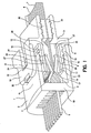
In Fig. 1 ist eine Kontaktierungseinrichtung 1 gemäß einer
ersten Ausführungsform der Erfindung dargestellt. Die Darstellung
zeigt einen Aufschnitt der Kontaktierungseinrichtung
1. Die Kontaktierungseinrichtung 1 weist ein Gehäuse 2 auf,
in dem erste Kontaktelemente 3 und zweite Kontaktelemente 4
angeordnet sind. Zumindest eines der ersten Kontaktelemente 3
oder eines der zweiten Kontaktelemente 4 stehen jeweils in
elektrischer Verbindung mit einem Kontaktstift 5, der aus einer
Fläche des Gehäuses 2, vorzugsweise aus der der Einführöffnung
des Gehäuses gegenüberliegenden Fläche herausragt.In Fig. 1 is a contacting device 1 according to a
first embodiment of the invention shown. The representation
shows a section of the contacting device
1. The contacting device 1 has a
Zwischen die ersten Kontaktelemente 3 und die zweiten Kontaktelemente
4 ist durch eine Einführöffnung des Gehäuses 2
ein Flachbandleiter 6 einführbar, der Leiterbahnen zumindest
auf der den zweiten Kontaktelementen 4 zugewandten Seite
trägt. Es kann mit einer solchen Kontaktierungseinrichtung
auch eine Leiterplatte kontaktiert werden. Between the
Die Leiterbahnen 7 sind im wesentlichen parallel zueinander
angeordnet, wobei die Anordnung der zweiten Kontaktelemente 4
so ausgeführt ist, dass sie auf die Leiterbahnen 7 aufsetzbar
sind und diese so kontaktieren können.The conductor tracks 7 are essentially parallel to one another
arranged, the arrangement of the
An dem Gehäuse 2 ist ein Verriegelungselement 8 angebracht,
das in Richtung der Einführrichtung des Flachbandleiters 6 an
dem Gehäuse 2 verschiebbar ist.A locking
Das Verriegelungselement 8 weist dazu eine erste Führungsfläche
9 und eine zweite Führungsfläche 10 auf, die an den Seiten
des Gehäuses 2 anliegen und eine Führung des Verriegelungselementes
an dem Gehäuse 2 ermöglichen.For this purpose, the locking
Weiterhin weist das Verriegelungselement 8 ein erstes Führungselement
11 und ein zweites Führungselement 12 auf. Das
erste und das zweite Führungselement 11, 12 sind im wesentlichen
zwischen den Führungsflächen 9, 10 und im wesentlichen
parallel zu ihnen angeordnet. Gehalten werden die Führungsflächen
9, 10 und die Führungselemente 11, 12 durch ein Trägerelement
13, das Teil des Verriegelungselementes 8 ist. Die
erste Führungsfläche 9 und das erste Führungselement 11 sind
an dem Trägerelement 13 so beabstandet angeordnet, dass eine
erste Wand 14 des Gehäuses 2 dazwischen verschieblich angeordnet
ist. Der Abstand zwischen der zweiten Führungsfläche
10 und dem zweiten Führungselement 12 ist ebenfalls so groß,
dass eine zweite Wand 15 des Gehäuses 2 darin verschieblich
angeordnet werden kann.Furthermore, the locking
Zwischen dem ersten Führungselement 11 und der ersten Wand 14
des Gehäuses 2 sowie zwischen dem zweiten Führungselement 12
und der zweiten Wand 15 des Gehäuses 2 sind Dichtungen 16 angeordnet,
die einen Schutz vor dem Eindringen von Feuchtigkeit
zwischen dem Gehäuse 2 und dem Verriegelungselement 8
bieten können. Between the
Das erste Führungselement 11 weist eine erste Gleitfläche 20
auf, die dem ersten Kontaktelement 3 zugewandt ist. Das erste
Kontaktelement 3 ist im wesentlichen federelastisch ausgebildet
und weist eine Kontaktierungsfläche 17 und einen Gleitabschnitt
18 auf, der auf der ersten Gleitfläche 20 des ersten
Führungselementes 11 aufliegt. Das erste Kontaktierungselement
3 ist an einer Haltewand 19 des Gehäuses 2 gehalten. Das
erste Kontaktierungselement 3 ist im wesentlichen so ausgebildet,
dass durch Bewegen des Gleitabschnittes 18 senkrecht
zum eingeführten Flachbandleiter 6 eine Kontaktierung der
Kontaktierungsfläche 17 mit den Leiterbahnen 7 des Flachbandleiters
6 oder ein bloßes Aufsetzen der Kontaktierungsfläche
auf den Flachbandleiter 6, wenn an der Aufsatzstelle keine
Leiterbahn 7 angeordnet ist, bewirkt wird.The
Durch Verschieben des Verriegelungselementes 8 in Richtung
des Gehäuses gleitet der Gleitabschnitt 18 des ersten Kontaktelementes
3 auf der ersten Gleitfläche 20 des ersten Führungselementes
11. Die erste Gleitfläche 20 des ersten Führungselementes
11 weist eine abgeschrägte Stufe 21 auf, durch
ein erster Gleitflächenabschnitt 22 und ein zweiter Gleitflächenabschnitt
23 der ersten Gleitfläche 20 voneinander getrennt
sind. Der erste Gleitflächenabschnitt und der zweite
Gleitflächenabschnitt 22, 23 liegen bezüglich des Flachbandleiters
6 auf verschiedenen Ebenen, wobei durch Verschieben
des Verriegelungselementes 8 in Richtung des Gehäuses das
erste Kontaktelement 3 mit seinem Gleitabschnitt 18 auf dem
ersten Gleitflächenabschnitt 22 entlang gleitet, dann durch
die abgeschrägte Stufe 21 in Richtung des Flachbandleiters 6
angehoben wird und darauf bis zum zweiten Gleitflächenabschnitt
23 gleitet.By moving the
Da der zweite Gleitflächenabschnitt 23 in Richtung des eingeführten
Flachbandleiters 6 versetzt ist, wird der Gleitabschnitt
18 des ersten Kontaktelementes 3 in Richtung des
Flachbandleiters 6 bewegt. Dadurch wird auch die Kontaktierungsfläche
17 des ersten Kontaktelementes 3 in Richtung des
Flachbandleiters 6 bewegt, so dass die Kontaktierungsfläche
17 auf den Flachbandleiter 6 gedrückt wird.Since the second sliding
Das zweite Kontaktierungselement 4 und das zweite Führungselement
12 sind im wesentlichen symmetrisch dazu ausgebildet,
wobei das zweite Kontaktierungselement 4 eine zweite Kontaktierungsfläche
24 und einen zweiten Gleitabschnitt 25 aufweist.
Das zweite Kontaktierungselement 4 ist ebenso wie das
erste Kontaktierungselement 3 an der Haltewand 19 des Gehäuses
2 befestigt. Das zweite Führungselement 12 weist eine
zweite Gleitfläche 26 auf, auf der der zweite Gleitabschnitt
des zweiten Kontaktelementes 4 gleitet. Die zweite Gleitfläche
26 weist einen dritten Gleitflächenabschnitt 27 und einen
vierten Gleitflächenabschnitt 28 auf, die voneinander durch
eine zweite abgeschrägte Stufe 29 getrennt sind.The
In Fig. 2 ist die Kontaktierungseinrichtung in einer den
Flachbandleiter 6 kontaktierenden Position dargestellt. Der
Flachbandleiter 6 befindet sich zwischen dem ersten und dem
zweiten Kontaktelement 3, 4, die mit ihren Kontaktierungsflächen
17, 24 auf die jeweiligen Leiterbahnen 7, sofern auf der
jeweiligen Seite des Flachbandleiters vorhanden, gepresst
sind. Die Kontaktierungskraft der Kontaktierungsflächen 17,
24 ergibt sich aus der Auslenkung der Gleitabschnitte 18, 25
in Richtung des Flachbandleiters 6 und der jeweiligen Federkraft
der Kontaktelemente 3, 4.In Fig. 2, the contacting device in one
Vorzugsweise kann der Flachbandleiter mit Dichtungskissen 30
versehen sein, die eine Öffnung in der Haltewand 13, durch
die der Flachbandleiter 6 geführt ist, gegenüber Feuchtigkeit
und Wasser abdichten.The flat ribbon conductor can preferably be provided with a
Die zwischen den Führungselementen 11, 12 und den Wänden des
Gehäuses angeordnete Dichtungen 16 sind in der Lage eine
Kraft aufzunehmen, die von dem Flachbandleiter 6 und dem jeweiligen
Kontaktelement 3, 4 an das jeweilige Führungselement
11, 12 weitergegeben wird. Die Kraft wird dann an die jeweilige
Wand 14, 15 des Gehäuses 2 weitergeleitet, und dort aufgenommen.
Auf diese Weise kann eine Verbiegung der Führungselemente
11, 12 durch die Kontaktierungskraft der Kontaktelemente
3, 4 auf den Flachbandleiter vermieden werden. Sind
keine Dichtungen vorgesehen, ist das jeweilige Führungselement
11, 12 so gestaltet, dass mit der jeweiligen Wand 14, 15
des Gehäuses in Verbindung steht, so dass die Kraft direkt an
das Gehäuse 2 weitergegeben wird.The between the
An den Außenseiten der beiden Wände 14, 15 des Gehäuses 2
sind erste Rastelemente 31 vorgesehen, um einerseits das Verriegelungselement
8 in einer nicht verriegelnden ersten Position
zu halten, so dass es nicht von dem Gehäuse 20 weggleiten
kann. Die ersten Rastelemente 31 wirken mit einer Verrastfläche
32 der jeweiligen Führungsfläche 9, 10 zusammen.
Die Führungsflächen 9, 10 sind vorzugsweise u-förmig ausgebildet,
wobei die Innenflächen der u-förmigen Form als Führungen
dienen. Die Führung wird durch die seitliche Begrenzung
der Rastelemente 31 und der Innenseite der U-Form gebildet.On the outer sides of the two
Es sind weiterhin zweite Rastelemente 33 vorgesehen, die es
ermöglichen, das Verriegelungselement 8 in einer verriegelten
Position zu halten, so dass keine unbeabsichtigte Verschiebung
des Verriegelungselementes 8 von dem Gehäuse weg erfolgen
kann.There are also second latching elements 33 that it
allow the
Im wesentlichen sind das Gehäuse 2, das Verriegelungselement
8, die ersten und zweiten Kontaktelemente 3, 4 symetrisch
aufgebaut, so dass bei der Montage nicht auf die jeweilige
Ausrichtung der einzelnen Teile zu achten ist. Dadurch wird
die Montage erheblich vereinfacht.The
Die ersten und zweiten Kontaktelemente 3, 4 können jeweils
einstückig als auch getrennt voneinander ausgebildet sein, je
nachdem, ob der Flachbandleiter 6 nur einseitig kontaktiert
werden muss oder ob der Flachbandleiter 6 auf beiden Seiten
voneinander elektrisch getrennte Leiterbahnen 7 aufweist.The first and
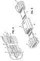
In Fig. 3 ist eine Verbindungseinrichtung zur Verbindung von
zwei Flachbandleitern 6 gezeigt, die zwei erfindungsgemäße
Kontaktierungseinrichtungen 1 aufweist. Die Verbindungseinrichtung
34 weist ein Gehäuse 35 auf, das im wesentlichen aus
zwei mit an ihren Haltewänden 19 aneinandergesetzten Kontaktierungseinrichtungen
1 gebildet ist. Dabei ist das Gehäuse
35 einteilig ausgeführt, so dass sich die Einführöffnungen
für die zu verbindenden Flachbandleiter 6 im wesentlichen gegenüberliegen.
An beiden offenen Enden des Gehäuses 35 sind
Verriegelungselemente 8 aufsetzbar, die im wesentlichen auf
gleiche Weise wie zuvor beschrieben mit dem Gehäuse und den
darin befindlichen Kontaktelementen zusammenwirken.In Fig. 3 is a connecting device for connecting
two
Wie in Fig. 4 gezeigt, liegen sich die jeweiligen Kontaktelemente
für die beiden Anschlussseiten im wesentlichen ebenfalls
gegenüber und sind elektrisch miteinander verbunden.
Vorzugsweise kann vorgesehen sein, dass die jeweiligen ersten
Kontaktelemente 3 und die jeweiligen zweiten Kontaktelemente
4 der beiden Anschlussseiten miteinander elektrisch verbunden
sind, vorzugsweise einteilig ausgeführt sind, wobei jedes der
ersten Kontaktelemente der einen Anschlussseite mit dem jeweils
gegenüberliegenden entsprechenden ersten Kontaktelement
der gegenüberliegenden Anschlussseite verbunden ist.As shown in Fig. 4, the respective contact elements are located
essentially also for the two connection sides
opposite and are electrically connected.
It can preferably be provided that the respective
Für den Fall, dass der Flachbandleiter nur auf einer Seite zu
kontaktierende Leiterbahnen 7 trägt, können das erste und das
zweite Kontaktelement 3, 4 einer der Anschlussseiten einteilig
mit dem jeweils zugeordneten ersten und zweiten Kontaktelement
3, 4 der jeweils anderen Anschlussseite ausgeführt
sein.In the event that the ribbon cable is only on one
Die erfindungsgemäße Kontaktierungseinrichtung ermöglicht eine Fixierung eines Flachbandleiters bzw. einer Leiterplatte, in dem mit Hilfe eines Verriegelungselementes eine hohe Klemmkraft auf den Flachbandleiter bzw. die Leiterplatte ausgeübt wird. Dadurch dass die Klemmkraft zwischen zwei Kontaktelementen ausgeübt wird, kann der Flachbandleiter sich nicht verbiegen und dadurch nicht beschädigt werden. Bei Kontaktieren einer festen Leiterplatte, kann somit eine Beschädigung durch Brechen der Leiterplatte vermieden werden.The contacting device according to the invention enables one Fixation of a ribbon cable or a printed circuit board, in which a high with the help of a locking element Clamping force exerted on the ribbon conductor or the printed circuit board becomes. Because of the clamping force between two contact elements is exercised, the ribbon cable can do not bend and are not damaged as a result. When contacting a solid circuit board, can therefore damage can be avoided by breaking the circuit board.
Bei Verwendung der erfindungsgemäßen Kontaktierungseinrichtung für eine Verbindungseinrichtung gewährleistet die hohe Haltekraft der Kontaktierungseinrichtung 1 eine zuverlässige und gegenüber Zugkraft belastbare Verbindung von zwei Flachbandleitern, zwei Leiterplatten, bzw. zwischen einer Leiterplatte und einem Flachbandleiter. When using the contacting device according to the invention for a connection device ensures the high Holding force of the contacting device 1 a reliable and connection of two ribbon cables that can withstand tensile forces, two circuit boards, or between a circuit board and a ribbon cable.
- 11
- Kontaktierungseinrichtungcontacting
- 22
- Gehäusecasing
- 33
- erstes Kontaktelementfirst contact element
- 44
- zweites Kontaktelementsecond contact element
- 55
- Kontaktstiftpin
- 66
- FlachbandleiterRibbon cable conductors
- 77
- Leiterbahnenconductor tracks
- 88th
- Verriegelungselementlocking element
- 99
- erste Führungsflächefirst management area
- 1010
- zweite Führungsflächesecond guide surface
- 1111
- erstes Führungselementfirst guide element
- 1212
- zweites Führungselementsecond guide element
- 1313
- Trägerelementsupport element
- 1414
- erste Wandfirst wall
- 1515
- zweite Wandsecond wall
- 1616
- Dichtungenseals
- 1717
- Kontaktierungsflächecontacting surface
- 1818
- Gleitabschnittsliding
- 1919
- Haltewandretaining wall
- 2020
- erste Gleitflächefirst sliding surface
- 2121
- erste abgeschrägte Stufefirst beveled step
- 2222
- erster Gleitflächenabschnittfirst sliding surface section
- 2323
- zweiter Gleitflächenabschnittsecond sliding surface section
- 2424
- zweite Kontaktierungsflächesecond contact area
- 2525
- zweiter Gleitflächenabschnittsecond sliding surface section
- 2626
- zweite Gleitflächesecond sliding surface
- 2727
- dritter Gleitflächenabschnittthird sliding surface section
- 2828
- vierter Gleitflächenabschnittfourth sliding surface section
- 2929
- zweite abgeschrägte Stufesecond sloping stage
- 3030
- Dichtungskissencushions
- 3131
- erste Rastelementefirst locking elements
- 3232
- VerrastflächeVerrastfläche
- 3333
- zweite Rastelementesecond locking elements
- 3434
- Verbindungseinrichtungconnecting device
- 3535
- Gehäusecasing
Claims (11)
wobei in dem Gehäuse (2) ein erstes und ein zweites Kontaktelement (3, 4) angeordnet sind, die mit Abstand so voneinander angeordnet sind, um zwischen sich den Kontaktträger (6) mit der Kontaktfläche (7) aufzunehmen, dadurch gekennzeichnet, dass
das Verriegelungselement (8) mit dem ersten und dem zweiten Kontaktelement (3, 4) gekoppelt ist, um bei einer Bewegung des Verriegelungselementes (8) bezüglich des Gehäuses (2) jeweils das erste und das zweite Kontaktelement (3, 4) gegeneinander zu bewegen, so dass der zwischen dem ersten und dem zweiten Kontaktelement (3, 4) anordbare Kontaktträger (6) verklemmbar ist, wobei dabei die Kontaktfläche (7) durch das erste oder das zweite Kontaktelement (3, 4) kontaktiert wird.Contacting device (1) for contacting a contact carrier (6) provided with a contact surface (7), with a housing (2), with a locking element (8) for clamping the contact carrier (6) in the housing,
wherein in the housing (2) a first and a second contact element (3, 4) are arranged, which are arranged at a distance from one another in order to receive between them the contact carrier (6) with the contact surface (7), characterized in that
the locking element (8) is coupled to the first and the second contact element (3, 4) in order to move the first and the second contact element (3, 4) against each other when the locking element (8) moves with respect to the housing (2) , so that the contact carrier (6) which can be arranged between the first and the second contact element (3, 4) can be clamped, the contact surface (7) being contacted by the first or the second contact element (3, 4).
Priority Applications (1)
| Application Number | Priority Date | Filing Date | Title |
|---|---|---|---|
| EP03027670A EP1432079A1 (en) | 2002-12-17 | 2003-12-03 | Contact device and connection device for a contact carrier |
Applications Claiming Priority (3)
| Application Number | Priority Date | Filing Date | Title |
|---|---|---|---|
| EP02028347 | 2002-12-17 | ||
| EP02028347 | 2002-12-17 | ||
| EP03027670A EP1432079A1 (en) | 2002-12-17 | 2003-12-03 | Contact device and connection device for a contact carrier |
Publications (1)
| Publication Number | Publication Date |
|---|---|
| EP1432079A1 true EP1432079A1 (en) | 2004-06-23 |
Family
ID=32395438
Family Applications (1)
| Application Number | Title | Priority Date | Filing Date |
|---|---|---|---|
| EP03027670A Withdrawn EP1432079A1 (en) | 2002-12-17 | 2003-12-03 | Contact device and connection device for a contact carrier |
Country Status (1)
| Country | Link |
|---|---|
| EP (1) | EP1432079A1 (en) |
Cited By (7)
| Publication number | Priority date | Publication date | Assignee | Title |
|---|---|---|---|---|
| WO2008066714A2 (en) * | 2006-11-15 | 2008-06-05 | Molex Incorporated | Edge connector with preload caps |
| WO2008143997A1 (en) * | 2007-05-17 | 2008-11-27 | Molex Incorporated | Cable connector |
| ITMI20091986A1 (en) * | 2009-11-12 | 2011-05-13 | Selecom S R L | CONNECTOR FOR PRINTED CIRCUITS FLEXIBLE WITH EASY CONNECTION |
| WO2012123222A1 (en) * | 2011-03-15 | 2012-09-20 | Robert Bosch Gmbh | Contact-making plug for making direct contact with a printed circuit board |
| WO2012142606A2 (en) | 2011-04-15 | 2012-10-18 | Hypertronics Corporation | High density electrical connector having a printed circuit board |
| CN103620885B (en) * | 2011-04-15 | 2016-11-30 | 希佩尔特罗尼克斯公司 | There is the high density electrical connector of printed circuit board (PCB) |
| CN112217064A (en) * | 2019-07-11 | 2021-01-12 | 泰连德国有限公司 | Contact carrier for providing contact for wiring in a vehicle |
Citations (8)
| Publication number | Priority date | Publication date | Assignee | Title |
|---|---|---|---|---|
| US3474387A (en) * | 1967-04-13 | 1969-10-21 | Elco Corp | Zero insertion force connector and contact therefor |
| US4220382A (en) * | 1978-12-15 | 1980-09-02 | Amp Incorporated | Bussing connector |
| US4400049A (en) * | 1981-08-12 | 1983-08-23 | Ncr Corporation | Connector for interconnecting circuit boards |
| US4480886A (en) * | 1982-03-02 | 1984-11-06 | Zetronic S.P.A. | Quick connector for a multi-conductor circuit |
| US4919626A (en) * | 1989-04-14 | 1990-04-24 | Itt Corporation | Connector for IC card |
| US5145381A (en) * | 1991-08-22 | 1992-09-08 | Amp Incorporated | Wedge driven elastomeric connector |
| EP0505744A2 (en) * | 1991-03-28 | 1992-09-30 | Richard Hirschmann GmbH & Co. | Connector for a printed circuit board |
| US5839916A (en) * | 1994-05-31 | 1998-11-24 | Sumitomo Wiring Systems, Ltd. | Device for connecting a flat cable to a wiring board |
-
2003
- 2003-12-03 EP EP03027670A patent/EP1432079A1/en not_active Withdrawn
Patent Citations (8)
| Publication number | Priority date | Publication date | Assignee | Title |
|---|---|---|---|---|
| US3474387A (en) * | 1967-04-13 | 1969-10-21 | Elco Corp | Zero insertion force connector and contact therefor |
| US4220382A (en) * | 1978-12-15 | 1980-09-02 | Amp Incorporated | Bussing connector |
| US4400049A (en) * | 1981-08-12 | 1983-08-23 | Ncr Corporation | Connector for interconnecting circuit boards |
| US4480886A (en) * | 1982-03-02 | 1984-11-06 | Zetronic S.P.A. | Quick connector for a multi-conductor circuit |
| US4919626A (en) * | 1989-04-14 | 1990-04-24 | Itt Corporation | Connector for IC card |
| EP0505744A2 (en) * | 1991-03-28 | 1992-09-30 | Richard Hirschmann GmbH & Co. | Connector for a printed circuit board |
| US5145381A (en) * | 1991-08-22 | 1992-09-08 | Amp Incorporated | Wedge driven elastomeric connector |
| US5839916A (en) * | 1994-05-31 | 1998-11-24 | Sumitomo Wiring Systems, Ltd. | Device for connecting a flat cable to a wiring board |
Cited By (13)
| Publication number | Priority date | Publication date | Assignee | Title |
|---|---|---|---|---|
| WO2008066714A2 (en) * | 2006-11-15 | 2008-06-05 | Molex Incorporated | Edge connector with preload caps |
| WO2008066714A3 (en) * | 2006-11-15 | 2008-08-21 | Molex Inc | Edge connector with preload caps |
| US7946889B2 (en) | 2006-11-15 | 2011-05-24 | Molex Incorporated | Edge connector with preload caps |
| CN101584086B (en) * | 2006-11-15 | 2012-01-11 | 莫列斯公司 | Edge connector with preload caps |
| WO2008143997A1 (en) * | 2007-05-17 | 2008-11-27 | Molex Incorporated | Cable connector |
| ITMI20091986A1 (en) * | 2009-11-12 | 2011-05-13 | Selecom S R L | CONNECTOR FOR PRINTED CIRCUITS FLEXIBLE WITH EASY CONNECTION |
| WO2012123222A1 (en) * | 2011-03-15 | 2012-09-20 | Robert Bosch Gmbh | Contact-making plug for making direct contact with a printed circuit board |
| WO2012142606A2 (en) | 2011-04-15 | 2012-10-18 | Hypertronics Corporation | High density electrical connector having a printed circuit board |
| EP2697871A2 (en) * | 2011-04-15 | 2014-02-19 | Hypertronics Corporation | High density electrical connector having a printed circuit board |
| CN103620885A (en) * | 2011-04-15 | 2014-03-05 | 希佩尔特罗尼克斯公司 | High density electrical connector having a printed circuit board |
| EP2697871A4 (en) * | 2011-04-15 | 2014-09-17 | Hypertronics Corp | High density electrical connector having a printed circuit board |
| CN103620885B (en) * | 2011-04-15 | 2016-11-30 | 希佩尔特罗尼克斯公司 | There is the high density electrical connector of printed circuit board (PCB) |
| CN112217064A (en) * | 2019-07-11 | 2021-01-12 | 泰连德国有限公司 | Contact carrier for providing contact for wiring in a vehicle |
Similar Documents
| Publication | Publication Date | Title |
|---|---|---|
| EP0730785B1 (en) | Terminal for electrical installations | |
| DE3709903C3 (en) | ELECTRIC CONNECTOR | |
| DE102015101893B4 (en) | conductor terminal | |
| EP1096606B1 (en) | Connecting terminal | |
| DE10355195B4 (en) | wire connection | |
| DE10340571B3 (en) | Clamp for holding flat objects | |
| EP1207588A1 (en) | Electrical connector for flat cable or flexible printed circuit | |
| DE102011051536A1 (en) | Clamping unit of an electrical terminal | |
| DE19857624B4 (en) | Connector assembly for flat circuit devices | |
| DE2638418A1 (en) | LOW PROFILE IC SOCKET | |
| WO2004040700A2 (en) | Plug-in connector for connecting two flat strip conductors and associated plug-in connector system | |
| DE102015119484A1 (en) | plug contact | |
| DE10103107A1 (en) | Connector block for connecting protective/zero conductors/PE terminals has a conductor rail, many connectors to connect conductors to the rail and a support block for modules. | |
| DE102016108825A1 (en) | Clamping arrangement and connection terminal | |
| EP1484822A1 (en) | Connector | |
| DE1765978B1 (en) | CIRCUIT BLOCK FOR ELECTRICAL CONNECTION USING PLUG CONNECTIONS OF ELECTRICAL CIRCUIT ELEMENTS | |
| DE102021104504A1 (en) | Terminal arrangement, connector terminal and electronic device | |
| DE102007017059B4 (en) | Socket for electrical components | |
| EP1432079A1 (en) | Contact device and connection device for a contact carrier | |
| DE10008932A1 (en) | Electrical plug for connecting to foil conductors has a plug body with contact pins, a plug casing forming a fastening part and a retaining gap for a foil conductor between the plug body and the fastening part. | |
| DE202004000419U1 (en) | Screwless conductor connection terminal | |
| DE2534292C2 (en) | ||
| DE1933201A1 (en) | Device for the power transmission connection of electrical lines | |
| DE2320202A1 (en) | ARRANGEMENT FOR THE ALTERNATE ELECTRICAL CONNECTION OF A MULTIPLE NUMBER OF COMPONENT CARRIERS (E.G. OF PRINTED CIRCUIT BOARDS) | |
| DE19706636A1 (en) | Electric connector for row of controlled loads especially magnetic valves |
Legal Events
| Date | Code | Title | Description |
|---|---|---|---|
| PUAI | Public reference made under article 153(3) epc to a published international application that has entered the european phase |
Free format text: ORIGINAL CODE: 0009012 |
|
| AK | Designated contracting states |
Kind code of ref document: A1 Designated state(s): AT BE BG CH CY CZ DE DK EE ES FI FR GB GR HU IE IT LI LU MC NL PT RO SE SI SK TR |
|
| AX | Request for extension of the european patent |
Extension state: AL LT LV MK |
|
| 17P | Request for examination filed |
Effective date: 20040817 |
|
| 17Q | First examination report despatched |
Effective date: 20040914 |
|
| AKX | Designation fees paid |
Designated state(s): DE FR GB IT |
|
| GRAP | Despatch of communication of intention to grant a patent |
Free format text: ORIGINAL CODE: EPIDOSNIGR1 |
|
| RBV | Designated contracting states (corrected) |
Designated state(s): DE FR GB IT |
|
| STAA | Information on the status of an ep patent application or granted ep patent |
Free format text: STATUS: THE APPLICATION IS DEEMED TO BE WITHDRAWN |
|
| 18D | Application deemed to be withdrawn |
Effective date: 20050803 |