EP1432545B1 - Rotary ultrasonic horn mounting apparatus and method for mounting - Google Patents
Rotary ultrasonic horn mounting apparatus and method for mounting Download PDFInfo
- Publication number
- EP1432545B1 EP1432545B1 EP20020756715 EP02756715A EP1432545B1 EP 1432545 B1 EP1432545 B1 EP 1432545B1 EP 20020756715 EP20020756715 EP 20020756715 EP 02756715 A EP02756715 A EP 02756715A EP 1432545 B1 EP1432545 B1 EP 1432545B1
- Authority
- EP
- European Patent Office
- Prior art keywords
- horn
- bearer
- anvil
- welding
- mounting
- Prior art date
- Legal status (The legal status is an assumption and is not a legal conclusion. Google has not performed a legal analysis and makes no representation as to the accuracy of the status listed.)
- Expired - Lifetime
Links
- 238000000034 method Methods 0.000 title claims description 13
- 238000003466 welding Methods 0.000 claims description 58
- 238000003825 pressing Methods 0.000 claims description 27
- 238000000926 separation method Methods 0.000 claims description 6
- 230000000712 assembly Effects 0.000 description 4
- 238000000429 assembly Methods 0.000 description 4
- 239000000463 material Substances 0.000 description 4
- 125000006850 spacer group Chemical group 0.000 description 4
- 238000002955 isolation Methods 0.000 description 3
- 230000003068 static effect Effects 0.000 description 3
- 238000013461 design Methods 0.000 description 2
- 239000012530 fluid Substances 0.000 description 2
- 230000003319 supportive effect Effects 0.000 description 2
- RTAQQCXQSZGOHL-UHFFFAOYSA-N Titanium Chemical compound [Ti] RTAQQCXQSZGOHL-UHFFFAOYSA-N 0.000 description 1
- XAGFODPZIPBFFR-UHFFFAOYSA-N aluminium Chemical compound [Al] XAGFODPZIPBFFR-UHFFFAOYSA-N 0.000 description 1
- 229910052782 aluminium Inorganic materials 0.000 description 1
- 230000005540 biological transmission Effects 0.000 description 1
- 230000007423 decrease Effects 0.000 description 1
- 238000005265 energy consumption Methods 0.000 description 1
- 239000004744 fabric Substances 0.000 description 1
- 238000009434 installation Methods 0.000 description 1
- 238000003754 machining Methods 0.000 description 1
- 230000013011 mating Effects 0.000 description 1
- 238000012986 modification Methods 0.000 description 1
- 230000004048 modification Effects 0.000 description 1
- 238000007789 sealing Methods 0.000 description 1
- 238000012421 spiking Methods 0.000 description 1
- 230000001360 synchronised effect Effects 0.000 description 1
- 229920001169 thermoplastic Polymers 0.000 description 1
- 239000004416 thermosoftening plastic Substances 0.000 description 1
- 229910052719 titanium Inorganic materials 0.000 description 1
- 239000010936 titanium Substances 0.000 description 1
- 238000013519 translation Methods 0.000 description 1
Images


Classifications
-
- B—PERFORMING OPERATIONS; TRANSPORTING
- B29—WORKING OF PLASTICS; WORKING OF SUBSTANCES IN A PLASTIC STATE IN GENERAL
- B29C—SHAPING OR JOINING OF PLASTICS; SHAPING OF MATERIAL IN A PLASTIC STATE, NOT OTHERWISE PROVIDED FOR; AFTER-TREATMENT OF THE SHAPED PRODUCTS, e.g. REPAIRING
- B29C66/00—General aspects of processes or apparatus for joining preformed parts
- B29C66/80—General aspects of machine operations or constructions and parts thereof
- B29C66/83—General aspects of machine operations or constructions and parts thereof characterised by the movement of the joining or pressing tools
- B29C66/834—General aspects of machine operations or constructions and parts thereof characterised by the movement of the joining or pressing tools moving with the parts to be joined
- B29C66/8341—Roller, cylinder or drum types; Band or belt types; Ball types
- B29C66/83411—Roller, cylinder or drum types
- B29C66/83413—Roller, cylinder or drum types cooperating rollers, cylinders or drums
-
- B—PERFORMING OPERATIONS; TRANSPORTING
- B23—MACHINE TOOLS; METAL-WORKING NOT OTHERWISE PROVIDED FOR
- B23K—SOLDERING OR UNSOLDERING; WELDING; CLADDING OR PLATING BY SOLDERING OR WELDING; CUTTING BY APPLYING HEAT LOCALLY, e.g. FLAME CUTTING; WORKING BY LASER BEAM
- B23K20/00—Non-electric welding by applying impact or other pressure, with or without the application of heat, e.g. cladding or plating
- B23K20/10—Non-electric welding by applying impact or other pressure, with or without the application of heat, e.g. cladding or plating making use of vibrations, e.g. ultrasonic welding
-
- B—PERFORMING OPERATIONS; TRANSPORTING
- B29—WORKING OF PLASTICS; WORKING OF SUBSTANCES IN A PLASTIC STATE IN GENERAL
- B29C—SHAPING OR JOINING OF PLASTICS; SHAPING OF MATERIAL IN A PLASTIC STATE, NOT OTHERWISE PROVIDED FOR; AFTER-TREATMENT OF THE SHAPED PRODUCTS, e.g. REPAIRING
- B29C65/00—Joining or sealing of preformed parts, e.g. welding of plastics materials; Apparatus therefor
- B29C65/02—Joining or sealing of preformed parts, e.g. welding of plastics materials; Apparatus therefor by heating, with or without pressure
- B29C65/08—Joining or sealing of preformed parts, e.g. welding of plastics materials; Apparatus therefor by heating, with or without pressure using ultrasonic vibrations
- B29C65/083—Joining or sealing of preformed parts, e.g. welding of plastics materials; Apparatus therefor by heating, with or without pressure using ultrasonic vibrations using a rotary sonotrode or a rotary anvil
- B29C65/087—Joining or sealing of preformed parts, e.g. welding of plastics materials; Apparatus therefor by heating, with or without pressure using ultrasonic vibrations using a rotary sonotrode or a rotary anvil using both a rotary sonotrode and a rotary anvil
-
- B—PERFORMING OPERATIONS; TRANSPORTING
- B29—WORKING OF PLASTICS; WORKING OF SUBSTANCES IN A PLASTIC STATE IN GENERAL
- B29C—SHAPING OR JOINING OF PLASTICS; SHAPING OF MATERIAL IN A PLASTIC STATE, NOT OTHERWISE PROVIDED FOR; AFTER-TREATMENT OF THE SHAPED PRODUCTS, e.g. REPAIRING
- B29C66/00—General aspects of processes or apparatus for joining preformed parts
- B29C66/006—Preventing damaging, e.g. of the parts to be joined
-
- B—PERFORMING OPERATIONS; TRANSPORTING
- B29—WORKING OF PLASTICS; WORKING OF SUBSTANCES IN A PLASTIC STATE IN GENERAL
- B29C—SHAPING OR JOINING OF PLASTICS; SHAPING OF MATERIAL IN A PLASTIC STATE, NOT OTHERWISE PROVIDED FOR; AFTER-TREATMENT OF THE SHAPED PRODUCTS, e.g. REPAIRING
- B29C66/00—General aspects of processes or apparatus for joining preformed parts
- B29C66/01—General aspects dealing with the joint area or with the area to be joined
- B29C66/05—Particular design of joint configurations
- B29C66/10—Particular design of joint configurations particular design of the joint cross-sections
- B29C66/11—Joint cross-sections comprising a single joint-segment, i.e. one of the parts to be joined comprising a single joint-segment in the joint cross-section
- B29C66/112—Single lapped joints
- B29C66/1122—Single lap to lap joints, i.e. overlap joints
-
- B—PERFORMING OPERATIONS; TRANSPORTING
- B29—WORKING OF PLASTICS; WORKING OF SUBSTANCES IN A PLASTIC STATE IN GENERAL
- B29C—SHAPING OR JOINING OF PLASTICS; SHAPING OF MATERIAL IN A PLASTIC STATE, NOT OTHERWISE PROVIDED FOR; AFTER-TREATMENT OF THE SHAPED PRODUCTS, e.g. REPAIRING
- B29C66/00—General aspects of processes or apparatus for joining preformed parts
- B29C66/40—General aspects of joining substantially flat articles, e.g. plates, sheets or web-like materials; Making flat seams in tubular or hollow articles; Joining single elements to substantially flat surfaces
- B29C66/41—Joining substantially flat articles ; Making flat seams in tubular or hollow articles
-
- B—PERFORMING OPERATIONS; TRANSPORTING
- B29—WORKING OF PLASTICS; WORKING OF SUBSTANCES IN A PLASTIC STATE IN GENERAL
- B29C—SHAPING OR JOINING OF PLASTICS; SHAPING OF MATERIAL IN A PLASTIC STATE, NOT OTHERWISE PROVIDED FOR; AFTER-TREATMENT OF THE SHAPED PRODUCTS, e.g. REPAIRING
- B29C66/00—General aspects of processes or apparatus for joining preformed parts
- B29C66/70—General aspects of processes or apparatus for joining preformed parts characterised by the composition, physical properties or the structure of the material of the parts to be joined; Joining with non-plastics material
- B29C66/73—General aspects of processes or apparatus for joining preformed parts characterised by the composition, physical properties or the structure of the material of the parts to be joined; Joining with non-plastics material characterised by the intensive physical properties of the material of the parts to be joined, by the optical properties of the material of the parts to be joined, by the extensive physical properties of the parts to be joined, by the state of the material of the parts to be joined or by the material of the parts to be joined being a thermoplastic or a thermoset
- B29C66/735—General aspects of processes or apparatus for joining preformed parts characterised by the composition, physical properties or the structure of the material of the parts to be joined; Joining with non-plastics material characterised by the intensive physical properties of the material of the parts to be joined, by the optical properties of the material of the parts to be joined, by the extensive physical properties of the parts to be joined, by the state of the material of the parts to be joined or by the material of the parts to be joined being a thermoplastic or a thermoset characterised by the extensive physical properties of the parts to be joined
- B29C66/7352—Thickness, e.g. very thin
-
- B—PERFORMING OPERATIONS; TRANSPORTING
- B29—WORKING OF PLASTICS; WORKING OF SUBSTANCES IN A PLASTIC STATE IN GENERAL
- B29C—SHAPING OR JOINING OF PLASTICS; SHAPING OF MATERIAL IN A PLASTIC STATE, NOT OTHERWISE PROVIDED FOR; AFTER-TREATMENT OF THE SHAPED PRODUCTS, e.g. REPAIRING
- B29C66/00—General aspects of processes or apparatus for joining preformed parts
- B29C66/80—General aspects of machine operations or constructions and parts thereof
- B29C66/82—Pressure application arrangements, e.g. transmission or actuating mechanisms for joining tools or clamps
- B29C66/822—Transmission mechanisms
- B29C66/8223—Worm or spindle mechanisms
-
- B—PERFORMING OPERATIONS; TRANSPORTING
- B29—WORKING OF PLASTICS; WORKING OF SUBSTANCES IN A PLASTIC STATE IN GENERAL
- B29C—SHAPING OR JOINING OF PLASTICS; SHAPING OF MATERIAL IN A PLASTIC STATE, NOT OTHERWISE PROVIDED FOR; AFTER-TREATMENT OF THE SHAPED PRODUCTS, e.g. REPAIRING
- B29C66/00—General aspects of processes or apparatus for joining preformed parts
- B29C66/80—General aspects of machine operations or constructions and parts thereof
- B29C66/82—Pressure application arrangements, e.g. transmission or actuating mechanisms for joining tools or clamps
- B29C66/822—Transmission mechanisms
- B29C66/8226—Cam mechanisms; Wedges; Eccentric mechanisms
-
- B—PERFORMING OPERATIONS; TRANSPORTING
- B29—WORKING OF PLASTICS; WORKING OF SUBSTANCES IN A PLASTIC STATE IN GENERAL
- B29C—SHAPING OR JOINING OF PLASTICS; SHAPING OF MATERIAL IN A PLASTIC STATE, NOT OTHERWISE PROVIDED FOR; AFTER-TREATMENT OF THE SHAPED PRODUCTS, e.g. REPAIRING
- B29C66/00—General aspects of processes or apparatus for joining preformed parts
- B29C66/80—General aspects of machine operations or constructions and parts thereof
- B29C66/82—Pressure application arrangements, e.g. transmission or actuating mechanisms for joining tools or clamps
- B29C66/824—Actuating mechanisms
- B29C66/8242—Pneumatic or hydraulic drives
- B29C66/82421—Pneumatic or hydraulic drives using an inflatable element positioned between the joining tool and a backing-up part
-
- B—PERFORMING OPERATIONS; TRANSPORTING
- B29—WORKING OF PLASTICS; WORKING OF SUBSTANCES IN A PLASTIC STATE IN GENERAL
- B29C—SHAPING OR JOINING OF PLASTICS; SHAPING OF MATERIAL IN A PLASTIC STATE, NOT OTHERWISE PROVIDED FOR; AFTER-TREATMENT OF THE SHAPED PRODUCTS, e.g. REPAIRING
- B29C66/00—General aspects of processes or apparatus for joining preformed parts
- B29C66/80—General aspects of machine operations or constructions and parts thereof
- B29C66/83—General aspects of machine operations or constructions and parts thereof characterised by the movement of the joining or pressing tools
- B29C66/834—General aspects of machine operations or constructions and parts thereof characterised by the movement of the joining or pressing tools moving with the parts to be joined
- B29C66/8341—Roller, cylinder or drum types; Band or belt types; Ball types
- B29C66/83411—Roller, cylinder or drum types
- B29C66/83415—Roller, cylinder or drum types the contact angle between said rollers, cylinders or drums and said parts to be joined being a non-zero angle
-
- B—PERFORMING OPERATIONS; TRANSPORTING
- B29—WORKING OF PLASTICS; WORKING OF SUBSTANCES IN A PLASTIC STATE IN GENERAL
- B29C—SHAPING OR JOINING OF PLASTICS; SHAPING OF MATERIAL IN A PLASTIC STATE, NOT OTHERWISE PROVIDED FOR; AFTER-TREATMENT OF THE SHAPED PRODUCTS, e.g. REPAIRING
- B29C66/00—General aspects of processes or apparatus for joining preformed parts
- B29C66/90—Measuring or controlling the joining process
- B29C66/92—Measuring or controlling the joining process by measuring or controlling the pressure, the force, the mechanical power or the displacement of the joining tools
- B29C66/924—Measuring or controlling the joining process by measuring or controlling the pressure, the force, the mechanical power or the displacement of the joining tools by controlling or regulating the pressure, the force, the mechanical power or the displacement of the joining tools
- B29C66/9261—Measuring or controlling the joining process by measuring or controlling the pressure, the force, the mechanical power or the displacement of the joining tools by controlling or regulating the pressure, the force, the mechanical power or the displacement of the joining tools by controlling or regulating the displacement of the joining tools
- B29C66/92611—Measuring or controlling the joining process by measuring or controlling the pressure, the force, the mechanical power or the displacement of the joining tools by controlling or regulating the pressure, the force, the mechanical power or the displacement of the joining tools by controlling or regulating the displacement of the joining tools by controlling or regulating the gap between the joining tools
-
- B—PERFORMING OPERATIONS; TRANSPORTING
- B29—WORKING OF PLASTICS; WORKING OF SUBSTANCES IN A PLASTIC STATE IN GENERAL
- B29C—SHAPING OR JOINING OF PLASTICS; SHAPING OF MATERIAL IN A PLASTIC STATE, NOT OTHERWISE PROVIDED FOR; AFTER-TREATMENT OF THE SHAPED PRODUCTS, e.g. REPAIRING
- B29C66/00—General aspects of processes or apparatus for joining preformed parts
- B29C66/80—General aspects of machine operations or constructions and parts thereof
- B29C66/82—Pressure application arrangements, e.g. transmission or actuating mechanisms for joining tools or clamps
- B29C66/822—Transmission mechanisms
- B29C66/8222—Pinion or rack mechanisms
-
- B—PERFORMING OPERATIONS; TRANSPORTING
- B29—WORKING OF PLASTICS; WORKING OF SUBSTANCES IN A PLASTIC STATE IN GENERAL
- B29C—SHAPING OR JOINING OF PLASTICS; SHAPING OF MATERIAL IN A PLASTIC STATE, NOT OTHERWISE PROVIDED FOR; AFTER-TREATMENT OF THE SHAPED PRODUCTS, e.g. REPAIRING
- B29C66/00—General aspects of processes or apparatus for joining preformed parts
- B29C66/80—General aspects of machine operations or constructions and parts thereof
- B29C66/82—Pressure application arrangements, e.g. transmission or actuating mechanisms for joining tools or clamps
- B29C66/824—Actuating mechanisms
- B29C66/8242—Pneumatic or hydraulic drives
-
- B—PERFORMING OPERATIONS; TRANSPORTING
- B29—WORKING OF PLASTICS; WORKING OF SUBSTANCES IN A PLASTIC STATE IN GENERAL
- B29C—SHAPING OR JOINING OF PLASTICS; SHAPING OF MATERIAL IN A PLASTIC STATE, NOT OTHERWISE PROVIDED FOR; AFTER-TREATMENT OF THE SHAPED PRODUCTS, e.g. REPAIRING
- B29C66/00—General aspects of processes or apparatus for joining preformed parts
- B29C66/90—Measuring or controlling the joining process
- B29C66/92—Measuring or controlling the joining process by measuring or controlling the pressure, the force, the mechanical power or the displacement of the joining tools
- B29C66/929—Measuring or controlling the joining process by measuring or controlling the pressure, the force, the mechanical power or the displacement of the joining tools characterized by specific pressure, force, mechanical power or displacement values or ranges
-
- B—PERFORMING OPERATIONS; TRANSPORTING
- B29—WORKING OF PLASTICS; WORKING OF SUBSTANCES IN A PLASTIC STATE IN GENERAL
- B29C—SHAPING OR JOINING OF PLASTICS; SHAPING OF MATERIAL IN A PLASTIC STATE, NOT OTHERWISE PROVIDED FOR; AFTER-TREATMENT OF THE SHAPED PRODUCTS, e.g. REPAIRING
- B29C66/00—General aspects of processes or apparatus for joining preformed parts
- B29C66/90—Measuring or controlling the joining process
- B29C66/95—Measuring or controlling the joining process by measuring or controlling specific variables not covered by groups B29C66/91 - B29C66/94
- B29C66/951—Measuring or controlling the joining process by measuring or controlling specific variables not covered by groups B29C66/91 - B29C66/94 by measuring or controlling the vibration frequency and/or the vibration amplitude of vibrating joining tools, e.g. of ultrasonic welding tools
- B29C66/9513—Measuring or controlling the joining process by measuring or controlling specific variables not covered by groups B29C66/91 - B29C66/94 by measuring or controlling the vibration frequency and/or the vibration amplitude of vibrating joining tools, e.g. of ultrasonic welding tools characterised by specific vibration frequency values or ranges
Definitions
- the present invention relates to ultrasonic horns. More particularly, the present invention relates to mounting an ultrasonic horn.
- ultrasonic welding In ultrasonic welding (sometimes referred to as “acoustic welding"), two parts to be joined (typically thermoplastic parts) are placed directly below a tool called an ultrasonic "horn” for delivering vibratory energy. These parts (or “workpieces”) are constrained between the horn and an anvil. The horn transfers energy to the welded part by expanding and contracting with the application of ultrasonic energy, typically from between approximately 20,000 hertz to approximately 40,000 hertz.
- An ultrasonic type vibratory welding system basically comprises an electrical generating means, an electrical ultrasonic converter for converting electrical energy into vibratory energy, the horn for delivering the vibratory energy into the weld zone, and an assembly for applying a static force to the workpieces so as to hold the workpiece in forced contact with the tool.
- the energy is imparted from the tool to the workpiece at a selected wavelength, frequency, and amplitude.
- the ultrasonic horn is an acoustical tool made of, for example, aluminum or titanium that transfers the mechanical vibratory energy to the part.
- ultrasonic welding is continuous ultrasonic welding. This type of ultrasonic welding is typically used for sealing fabrics and films, or other workpieces which can be formed into a "web" and fed through the welding apparatus.
- the ultrasonic horn is typically stationary and the part is moved beneath it.
- One type of continuous ultrasonic welding uses a rotationally fixed bar horn and a rotationally fixed anvil surface. The workpiece is pulled between the bar horn and the anvil. The horn typically extends longitudinally towards the workpiece and the vibrations travel axially along the horn into the workpiece.
- the horn is a rotary type which is cylindrical and rotates about a longitudinal axis.
- the input vibration is in the axial direction of the horn and the output vibration is in the radial direction of the horn.
- the horn is placed close to an anvil which typically is also able to rotate so that the workpiece to be welded (or bonded) passes between the cylindrical surfaces at a linear velocity which substantially equals the tangential velocity of the cylindrical surfaces.
- This type of ultrasonic welding system is described in U.S. Pat. No. 5,976,316 , incorporated by reference in its entirety herein.
- the juxtaposition of the anvil to the horn allowed a static force to be provided to the workpiece, allowing the transmission of the ultrasonic energy to the workpiece.
- This static force was typically maintained by providing a pinching force to the workpiece from a force application system (e.g., using a fluid hydraulic system) which forced the horn radially towards the longitudinal axis of the anvil.
- a force application system e.g., using a fluid hydraulic system
- ultrasonic welding systems were developed which maintained a gap between the anvil and the horn. This gap was typically narrower than the thickness of the workpiece.
- the support structure was necessarily rigid, to maintain the angular position of both the horn and the anvil with respect to each other. Mis-aligning the surfaces of the horn and anvil caused poor welding and loss of product.
- attempting to adjust the distance of the gap in this type of system allowed an unacceptable level of movement to be introduced into the system, once again causing mis-adjustment of the surfaces of the horn and anvil.
- US-A-6 099 670 discloses a method of high speed bonding at least one material, including applying acoustic energy, using an acoustic horn and an anvil, to the material.
- the invention includes an apparatus comprising an ultrasonic horn as defined in claim 1.
- the horn is mounted to a support structure and includes a first mounting surface.
- An anvil is mounted to the support structure and spaced from the ultrasonic horn.
- the anvil has a first bearer surface.
- a bearer assembly supportably links the first mounting surface to the first bearer surface.
- Another aspect of the invention includes a method for mounting an ultrasonic welding horn as defined in claim 6 comprising securing the ultrasonic horn to a support structure.
- the horn has a welding surface and a first mounting surface.
- An anvil having a pressing surface and a first bearing surface is disposed such that the pressing surface is proximate to the welding surface.
- the welding surface and the pressing surface are biased towards each other.
- a linkage structure links the first bearing surface to the first mounting surface so as to prevent the pressing surface and the welding surface from coming into contact.
- Ultrasonic welding device 10 includes at least one horn assembly 12, horn assembly guide 14, anvil roll 16 having longitudinal axis 17 (shown running into the page in FIG. 1 ) and mounting plate 18.
- Horn assembly guide 14 and anvil roll (or anvil, or roll) 16 are mounted to mounting plate 18 so as to dispose ultrasonic horn 20 included in horn assembly 12 proximate to anvil roll 16.
- web 22 (shown in dotted lines before being welded and solid lines after welding) is threaded through welding device 10 so as to ride on axially extending pressing surface 19 of anvil roll 16 between pressing surface 19 and ultrasonic horn 20. While one horn assembly 12 is illustrated, any number may be utilized without departing from the scope of the invention as defined by the appended claims.
- Faceplates 24 are provided for structural support of horn assembly 12, and may include stiffening braces 26.
- Pressure system 30 (shown in dotted lines in FIG.1 ) is included with horn assembly 12 to drive the ultrasonic horn 20 radially inward towards the anvil roll 16.
- a pressure system could be used to drive the anvil towards the longitudinal axis of the horn, or simultaneously drive the horn and anvil towards each other.
- This pressure system can utilize any number of methods to generate force, including utilizing pneumatic, mechanical (e.g., gear driven, screw jack), or electronic apparatus, as would be known to one skilled in the art.
- Ultrasonic horn 12 is allowed to translate radially inward along tracks (or grooves) 31b in horn assembly guide 14, as shown in Fig. 1A .
- a person skilled in the art would realize the illustrated apparatus is exemplary of one way to allow the radially inward movement of each ultrasonic horn 20 with respect to anvil roll 16 and that any number of methods may be used.
- cam followers 31 a are secured to each horn assembly 12 and are inserted into grooves 3 1 b in horn assembly guide 14. The relation of cam followers 31a in grooves 31b allows horn assembly 12 (including horn 20) to translate radially toward and away (arrow 29a) from anvil 16.
- Cam followers 31a and grooves 31b prevent horn assembly 12 from moving transversely (into and out of the page when viewing FIG. 1A and in the direction of arrow 29b in FIG. 1 ).
- Translation of horn assembly 12 in an axial direction shown by arrow 29c is limited by a series of individual bearings 31c, which abut stop surfaces 31 d on horn assembly guide 14.
- Rotation of horn assembly 12 about the axis defined by arrow 29c is also prevented by cam followers 31a.
- a slight amount of clearance is provided between inner wall 31 e of grooves 31 b and cam followers 31 a, allowing each horn assembly 12 to rotate along the longitudinal direction (arrows 29e and 29f) about axis 29b (see FIG. 1 ). Stop surfaces 31d limit this longitudinal rotation of horn assembly 12.
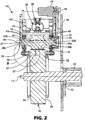
- Bearer rings 32 are included as part of anvil roll 16, and are mounted on radially extending faces 34 of anvil roll 16 (e.g., by bolting, welding, etc.). Bearer rings 32 are concentric with anvil roll 16, as best shown in FIG. 2.
- FIG. 2 illustrates a cross-section taken through horn assembly 12 and is representative of any horn assembly mounted according to the present invention.
- Bearing rings 32 extend axially from radially extending faces 34 of anvil roll 16, forming axially extending bearer surfaces 36.
- Anvil roll 16 is machined such that pressing surface 19 of anvil roll 16 and bearer surface 36 of bearer rings 32 each are substantially concentric to longitudinal axis 17 of anvil roll 16. Additionally, the radial distance (indicated by reference number 37 in FIG. 2 ) between the pressing surface 19 and the bearer surface 36 is maintained at a substantially constant distance, preferably at approximately 3.169 inches (80.493 mm), regardless of the rotational position of anvil 16.
- bearer surface 36 radially spaced from pressing surface 19, it should be understood that bearer surface 36 could be placed anywhere on anvil roll 16 (or on any part of the assembly making up the anvil roll, such as bearer rings 32) with respect to pressing surface 19.
- horn 20 includes welding portion 20a and mounting (or shaft) portions 20b.
- Outer surface 38 of horn 20 can similarly be divided into welding surface 38a and mounting (or bearer) surfaces 38b. While the illustrated embodiment shows mounting surfaces 38b disposed longitudinally on both sides of the welding surface 38a, it should be understood that mounting surfaces may be disposed anywhere on hom 20. Additionally, any number of mounting surfaces may be used.
- ultrasonic welding device 10 As web 22 is fed through ultrasonic welding device 10, it passes between welding surface 38a of horn 20 and pressing surface 19 of anvil roll 16 (which typically has various surface protrusions, as is known to one skilled in the art) transferring the ultrasonic energy from horn 20 to web 22 as it is pinched between horn 20 and anvil 16, thereby welding web 22.
- Pressure system 30 maintains a constant force on horn assembly 12, providing a compressive (pinching) force on web 22 by pushing horn frame 42 (and thus horn 20) radially inward towards anvil roll 16.
- Horn frame 42 is part of horn assembly 12 and is secured to mounting plate 18 to provide structural support to the horn assembly 12.
- pressure system 30 utilizes an air filled bladder 30A to direct horn 20 radially inward towards anvil 16.
- One side of bladder 30A is mounted to horn frame 42, and the other side of bladder 30a is mounted to support 39.
- Support 39 extends transversely (out of the page when viewing FIG. 2 ) across welding apparatus 10 and then in the axial direction (as defined by longitudinal axis 17) where it is secured to mounting plate 18.
- air or other fluid
- Isolating devices 40 are attached to shaft portions 20B of ultrasonic horn 20. Isolating devices 40 are used to isolate the vibrational energy of horn 20 from the remainder of horn assembly, including horn frame 42 and faceplate 24.
- One type of isolation device is a set-screw type nodal mount as illustrated in FIGs. 2 , 3A and 3B . Set-screw nodal mounts are adjustable and allow for a wide variety of materials to be used in web 22. Other types of isolation devices, however, may be preferable in certain applications and may be used in the inventive system without departing from the scope of the invention as defined by the appended claims. Examples of other types of isolating devices include but are not limited to nodal mounts such as those disclosed in U.S. Pat. Nos.
- Gear motor 44 is mounted to horn frame 42 and is used to rotate horn 20 about horn longitudinal axis 46. Typically, gear motor 44 is interconnected to horn 20 through timing pulley 48. Horn bearings 49 are disposed circumferentially about isolating devices 40, allowing horn 20 and isolating devices 40 to rotate with respect to the remainder of horn assembly 12.
- Anvil 16 is secured to mounting plate 18 by shaft 50 which extends through anvil 16 along longitudinal axis 17.
- Shaft 50 transfers torque to anvil 16 from a rotational source (not shown).
- the rotational speed of shaft 50 and gear motor 44 are synchronized so as to provide substantially the same tangential velocity at welding surface 38a of horn 20 and axially extending pressing surface 19 of anvil 16, so that drag on the workpiece material (i.e., web 22) is minimized.
- Shaft 50 is rotationally fixed with respect to anvil 16, and shaft bearing 52 is mounted between shaft 50 and mounting plate 18 to allow shaft 50 to be supported by mounting plate 18 while still allowing rotation of shaft 50 with respect to mounting plate 18.
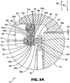
- bearer assemblies (or linkage structures) 60 provide a linkage between mounting surfaces 38b of horn 20 and bearer surfaces 36 on bearer rings 32.
- Bearer assembly 60 acts to isolate the energy resident in shaft portions 20b and mounting surfaces 38b of horn 20 from bearer surfaces 36 and bearer rings 32 of anvil roll 16. Additionally, bearer assembly 60 acts to supportably link mounting surface 38a of horn 20 and bearer surface 36 of anvil roll 16.
- a pre-determined separation distance (or gap) 62 can be maintained between welding surface 38a of horn 20 and pressing surface 19 of anvil roll 16.
- gap 62 is set between approximately 0.0025 inch (0.0635 mm) to approximately 1 inch (25.4 mm), depending upon the application. Note that in FIG. 3A , the web has been omitted so as to clearly illustrate gap 62. Additionally, it should be noted that bearer assembly 60 described with respect to FIG. 3A is representative of the other bearer assemblies previously illustrated.
- bearer assembly 60 includes isolating device 40 (having set-screw 41a) and horn bearings 49.
- first support ring 64 is disposed annularly about and press fit to outer face 41b of isolating device 40.
- Horn bearings 49 extend annularly about and are press fit onto first support ring 64.
- Bearing spacer 65 extends annularly about first support ring 64 and is disposed axially between horn bearings 49.
- Second support ring 66 extends annularly about horn bearings 49 and bearing spacer 65 and is press fit onto horn bearings 49.
- First and second support rings 64 and 66 in conjunction with bearing spacer 65 facilitate installation of horn bearings 49 into faceplate 24.
- Eccentric shaft 70 extends transversely through aperture 71 in faceplate 24, in a direction parallel to the longitudinal axis of anvil 16 and horn 20. Eccentric shaft 70 includes non-anvil end 72 and anvil end 74. Eccentric shaft 70 is supported by first and second thrust bearings 78a and 78b disposed annularly about eccentric shaft 70 at first and second shaft diameters 80a and 80b. First and second thrust bearings 80a and 80b are seated within faceplate 24 and include annular rims 82a and 82b. Annular shoulders 83a and 83b are disposed internally in aperture 71 and abut about annular rims 82a and 82b, respectively.
- Threaded shaft collar 76 is preferably threaded on to non-anvil end 72 of eccentric shaft 70 to secure thrust bearings 78a and 78b in aperture 71.
- annular shoulders 83a and 83b in combination with thrust bearings 78a and 78b prevent the transverse movement of eccentric shaft 70 within aperture 71 while allowing rotation of eccentric shaft 70 within aperture 71.
- Cam follower bearing 84 is press fit annularly about anvil end 74 of eccentric shaft 70.
- Follower surface 86 of cam follower bearing 84 engages bearer surface 36 of bearer ring 32.
- horn 20 (as part of horn assembly 12) is driven radially towards anvil 16 ( FIGs. 3A and 3B ), in the direction of arrow 94 by pressure system 30 (described previously with respect to FIGs. 1 and 2 ).
- faceplate 24, isolation device 40, first and second support rings 64 and 66, bearing spacer 65, horn bearings 49 thrust bearings 78a and 78b, eccentric shaft 70 and cam follower bearing 84 translate inward as well.
- Rotation of horn 20 is isolated from faceplate 24 by horn bearings 49.
- Ultrasonic vibrations are isolated from faceplate 24 by isolating device 40.
- eccentric shaft 70 extends through faceplate 24 at aperture 71, downward force is translated through thrust bearings 78a and 78b, to eccentric shaft 70 and finally to cam follower bearing 84.
- follower surface 86 of cam follower bearing 84 is translated inward until it engages bearer surface 36 of bearer ring 32, preventing further inward movement of cam follower bearing 84.
- Cam follower bearing 84 allows anvil 16 to rotate with respect to bearer assembly 60.
- the radial separation distance of the bearer assembly 60 (i.e., the distance between mounting surface 38b of horn 20 and bearer surface 36 of anvil 16) is set so that mounting surface 38b of horn 20 engages bearer surface 36 of anvil 16 before welding surface 38a of horn 20 engages pressing surface 19 of anvil. This allows radial forces to translate directly from horn assembly 12 to anvil 16 while still maintaining gap 62 (preventing contact) between welding surface 38a of horn 20 and pressing surface 19 of anvil.
- horn 20 and anvil 16 are in continual engagement, the design of the support system of the welding device 10 as well as the pressure system 30 can be simplified. For example, since the horn 20 is allowed to translate inward until cam follower bearing 84 engages bearer ring 32, pressure system 30 can be set to provide a level of compressive force to web 22 well above any reactive force generated by variances in thickness of web 22 or by runout of horn 20 or anvil 16. Runout occurs when the horn or anvil is mounted such that rotation occurs about an axis slightly off center resulting in eccentric rotation.
- the various components of the welding device 10 e.g., bearing rings 32, horn 20, anvil roll 16
- the various components of the welding device 10 are typically machined to eliminate run out, slight variances can still occur.
- the ability to overcome these variances due to web thicknesses or slight eccentricities as well as the ability to maintain the pre-determined distance when "holes" in the web would otherwise cause anvil 16 and horn 20 contact (thereby generating an overload condition) allows the welding device 10 to be run at a higher speed (i.e., the web is run at a higher throughput).
- the inventive mounting system eliminates overload downtime as well as maintaining quality product output at higher web throughput than was attainable by previous ultrasonic welding devices.
- the support structure i.e., mounting plate 18, shown previously
- the support structure for the horn and the anvil does not need to be built to provide a large amount of stiffness (assuring angular position) and can be reduced in size and in cost from that required in previous gap type ultrasonic welding systems.
- Worm 88 and worm gear 90 allow eccentric shaft 70 to be rotated by an operator, forcing the bearer assembly 60 radially inward in the direction of arrow 94 or allowing the bearer assembly 60 to travel radially outward in the direction of arrow 92.
- bearer assembly 60 is urged radially outward (direction 92) horn 20 is lifted at mounting surface 38b, causing gap 62 to widen.
- cam follower bearing 84 is allowed to move radially inward (direction 94) pressure system 30 (previously described with respect to FIGs.
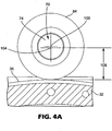
- FIG. 4A is a view taken from anvil end 74 of eccentric shaft 70, illustrating the use of eccentric shaft 70 to translate the bearer assembly 60 radially inward or outward (i.e., "lengthen” or “shorten” the bearer assembly 10).
- eccentric shaft 70 has a central axis 100 disposed through the center of anvil end 74 (the eccentric end) of eccentric shaft 70 and a longitudinal axis 104 about which eccentric shaft 70 rotates.
- eccentric shaft 70 The distance between these axises is commonly referred to as the "eccentricity of the shaft.” As illustrated, disposing eccentric shaft rotationally so as to position central axis 100 of anvil end (or eccentric portion) of eccentric shaft 70 radially outward from longitudinal (or rotational) axis 104 of shaft 70 defines a first distance 108 from bearer surface 36 of bearer ring 32 to longitudinal axis 104 of eccentric shaft 70.
- Eccentric shaft 70 can be rotated by the operator about longitudinal axis 104 until central axis 100 of eccentric shaft 70 is disposed generally radially inward from longitudinal axis 104 of shaft 70, as shown in FIG. 4B .
- Rotating eccentric shaft 70 in this manner defines a second larger distance 110 from bearer surface 36 of bearer ring 32 to longitudinal axis 104. It should become evident that by changing the rotational position of eccentric shaft 70, the distance between longitudinal axis 104 of eccentric shaft 70 and top surface 106 of bearer ring 32 can be varied from between first distance 108 (shown in FIG. 4A ) and second distance 110 (shown in FIG. 4B ). This distance can be defined as variable distance 112.
- the "length" of the bearer assembly 60 or in other words, the distance defined by bearer assembly 60 between mounting surface 38b of horn 20 and bearer surface 36 of anvil 16 can be varied.
- An operator is able to vary the length of bearer assembly 60 by rotating eccentric shaft 70, thereby changing the distance between horn 20 and anvil 16.
- This allows the operator to adjust the size of gap 62 (as previously discussed with respect to FIGs. 3A and 3B ) while still continuously maintaining a supportive link between anvil 16 and horn 20.
- variable distance 112 is also the distance through which gap 62 can be adjusted and is also equal to twice the eccentricity of shaft 70.
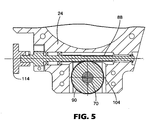
- FIG. 5 illustrates worm 88 and worm gear 90 used in combination with eccentric shaft 70.
- Worm 88 preferably has knob 114 attached so as to allow an operator to easily grasp and rotate worm 88. Teeth on worm 88 engage mating teeth on worm gear 90.
- Worm gear 90 is press fit about or pinned to eccentric shaft 70 so that it is locked rotationally to eccentric shaft 70.
- knob 114 By turning knob 114, ridges of worm 88 drive worm gear 90 and eccentric shaft 70 either clockwise or counterclockwise (as when viewing FIG. 5 ) depending on the direction knob 114 is rotated.
- the operator can adjust gap 62 without disassembling of the welding device 10. Adjusting the length of bearer assemblies 60 on opposite ends of horn 20 (as illustrated in FIG.
- horn assembly 12 allows the operator to manually compensate for any variation in dimensions (i.e., due to machining tolerances, etc.) in horn 20 or anvil 16.
- the operator can slightly rotate the horn assembly 12 along its longitudinal axis (as discussed with respect to FIG. 1A ) to adjust the angular relation of welding surface 38a of horn 16 with respect to pressing surface 19 of anvil 16.
- bearer assembly 60 While one adjustment embodiment has been discussed with respect to bearer assembly 60, it would be understood by a person skilled in the art that other adjustment methods could be used without departing from the spirit and scope of the claims (e.g., taper (wedge) blocks, replaceable shims, lever arms, differential screws, thermal expansion, etc.).
- the bearer assembly 60 can be reconfigured such that the apparatus utilized to adjust the length of the bearer assembly 60 contacts a surface on the horn, or in the middle of the bearer assembly versus directly contacting a surface on the anvil.
Abstract
Description
- The present invention relates to ultrasonic horns. More particularly, the present invention relates to mounting an ultrasonic horn.
- In ultrasonic welding (sometimes referred to as "acoustic welding"), two parts to be joined (typically thermoplastic parts) are placed directly below a tool called an ultrasonic "horn" for delivering vibratory energy. These parts (or "workpieces") are constrained between the horn and an anvil. The horn transfers energy to the welded part by expanding and contracting with the application of ultrasonic energy, typically from between approximately 20,000 hertz to approximately 40,000 hertz. An ultrasonic type vibratory welding system basically comprises an electrical generating means, an electrical ultrasonic converter for converting electrical energy into vibratory energy, the horn for delivering the vibratory energy into the weld zone, and an assembly for applying a static force to the workpieces so as to hold the workpiece in forced contact with the tool. The energy is imparted from the tool to the workpiece at a selected wavelength, frequency, and amplitude. The ultrasonic horn is an acoustical tool made of, for example, aluminum or titanium that transfers the mechanical vibratory energy to the part.
- One type of ultrasonic welding is continuous ultrasonic welding. This type of ultrasonic welding is typically used for sealing fabrics and films, or other workpieces which can be formed into a "web" and fed through the welding apparatus. In continuous welding, the ultrasonic horn is typically stationary and the part is moved beneath it. One type of continuous ultrasonic welding uses a rotationally fixed bar horn and a rotationally fixed anvil surface. The workpiece is pulled between the bar horn and the anvil. The horn typically extends longitudinally towards the workpiece and the vibrations travel axially along the horn into the workpiece. In another type of continuous ultrasonic welding, the horn is a rotary type which is cylindrical and rotates about a longitudinal axis. The input vibration is in the axial direction of the horn and the output vibration is in the radial direction of the horn. The horn is placed close to an anvil which typically is also able to rotate so that the workpiece to be welded (or bonded) passes between the cylindrical surfaces at a linear velocity which substantially equals the tangential velocity of the cylindrical surfaces. This type of ultrasonic welding system is described in
U.S. Pat. No. 5,976,316 , incorporated by reference in its entirety herein. - The juxtaposition of the anvil to the horn allowed a static force to be provided to the workpiece, allowing the transmission of the ultrasonic energy to the workpiece. This static force was typically maintained by providing a pinching force to the workpiece from a force application system (e.g., using a fluid hydraulic system) which forced the horn radially towards the longitudinal axis of the anvil. The problem with this method of securing the workpiece was that when the workpiece being welded became extremely thin, or contained holes, the horn and the anvil could physically contact each other. When the horn contacted the anvil, a large spike in energy consumption occurred through the system, similar to an electrical short circuit. As throughput speeds of the workpiece were increased, the level of energy introduced through the horn was also increased, causing the frequency of the surges of energy which occurred during contact of the horn and anvil to exponentially increase. These high spikes of energy forced the machine into an overload condition causing it to shut down as well as potentially causing holes or brittle spots to be generated in the product. Thus, the amount of energy which could be introduced through the ultrasonic horn was limited in order to prevent the machine from entering into an overload condition. Consequently, the throughput speed of the workpiece or product had to be reduced to allow enough energy to be transferred to the workpiece to generate an adequate weld. In short, the process became inefficient and caused product damage when the horn and anvil contacted one another.
- To remedy this problem, ultrasonic welding systems were developed which maintained a gap between the anvil and the horn. This gap was typically narrower than the thickness of the workpiece. The necessity to provide a pinching (or holding) force on the product, while maintaining a separation between the horn and the anvil, required a large and stiff support structure for both the horn and anvil. The support structure was necessarily rigid, to maintain the angular position of both the horn and the anvil with respect to each other. Mis-aligning the surfaces of the horn and anvil caused poor welding and loss of product. Similarly, attempting to adjust the distance of the gap in this type of system allowed an unacceptable level of movement to be introduced into the system, once again causing mis-adjustment of the surfaces of the horn and anvil. It is desirable, therefore, to provide a way to mount an ultrasonic horn next to an anvil so that a gap is maintained between the horn and the anvil, while maintaining the angular position of the horn with respect to the anvil, without requiring an overly large support structure.
-
US-A-6 099 670 discloses a method of high speed bonding at least one material, including applying acoustic energy, using an acoustic horn and an anvil, to the material. - The invention includes an apparatus comprising an ultrasonic horn as defined in claim 1. The horn is mounted to a support structure and includes a first mounting surface. An anvil is mounted to the support structure and spaced from the ultrasonic horn. The anvil has a first bearer surface. A bearer assembly supportably links the first mounting surface to the first bearer surface.
- Another aspect of the invention includes a method for mounting an ultrasonic welding horn as defined in claim 6 comprising securing the ultrasonic horn to a support structure. The horn has a welding surface and a first mounting surface. An anvil having a pressing surface and a first bearing surface is disposed such that the pressing surface is proximate to the welding surface. The welding surface and the pressing surface are biased towards each other. A linkage structure links the first bearing surface to the first mounting surface so as to prevent the pressing surface and the welding surface from coming into contact.
- The present invention will be further explained with reference to the drawing figures referenced below, wherein like structure is referred to by like numerals throughout the several views.
- It should be noted that certain portions of the invention may be illustrated as out of proportion with other portions in order to clearly illustrate various aspects of the invention.
-
FIG. 1 is an elevational view of an ultrasonic welding system. -
FIG. 1A is a cross-sectional view of a guide portion of an ultrasonic welding system, as taken along line 1A-1A ofFIG. 1 . -
FIG. 2 is a cross-sectional view taken along line 2-2 ofFIG. 1 . -
FIG. 3A is a detailed view of the area indicated byreference number 3 inFIG. 2 . -
FIG. 3B is the same view asFIG. 3A , but with a larger gap between the welding surface of the horn and the pressing surface of the anvil. -
FIG. 4A is an elevational view of a portion of the bearer assembly taken from the anvil end of the eccentric shaft. -
FIG. 4B is an elevational view of a portion of the bearer assembly taken from the anvil end of the eccentric shaft. -
FIG. 5 is a cross-sectional view of the bearer assembly. While the above-identified drawings set forth one preferred embodiment, other embodiments of the present invention are also contemplated, as noted in the discussion. This disclosure presents an illustrative embodiment of the present invention by the way of representation and not limitation. Numerous other modifications and embodiments can be devised by those skilled in the art which fall within the scope and spirit of the principles of this invention. - One embodiment of an ultrasonic welding device is illustrated at 10 in
FIG. 1 .Ultrasonic welding device 10 includes at least onehorn assembly 12,horn assembly guide 14,anvil roll 16 having longitudinal axis 17 (shown running into the page inFIG. 1 ) and mountingplate 18. -
Horn assembly guide 14 and anvil roll (or anvil, or roll) 16 are mounted to mountingplate 18 so as to disposeultrasonic horn 20 included inhorn assembly 12 proximate toanvil roll 16. In operation, web 22 (shown in dotted lines before being welded and solid lines after welding) is threaded throughwelding device 10 so as to ride on axially extending pressingsurface 19 ofanvil roll 16 between pressingsurface 19 andultrasonic horn 20. While onehorn assembly 12 is illustrated, any number may be utilized without departing from the scope of the invention as defined by the appended claims.Faceplates 24 are provided for structural support ofhorn assembly 12, and may include stiffening braces 26. - Pressure system 30 (shown in dotted lines in
FIG.1 ) is included withhorn assembly 12 to drive theultrasonic horn 20 radially inward towards theanvil roll 16. In an alternate embodiment, a pressure system could be used to drive the anvil towards the longitudinal axis of the horn, or simultaneously drive the horn and anvil towards each other. This pressure system can utilize any number of methods to generate force, including utilizing pneumatic, mechanical (e.g., gear driven, screw jack), or electronic apparatus, as would be known to one skilled in the art. -
Ultrasonic horn 12 is allowed to translate radially inward along tracks (or grooves) 31b inhorn assembly guide 14, as shown inFig. 1A . A person skilled in the art would realize the illustrated apparatus is exemplary of one way to allow the radially inward movement of eachultrasonic horn 20 with respect toanvil roll 16 and that any number of methods may be used. In the embodiment shown,cam followers 31 a are secured to eachhorn assembly 12 and are inserted intogrooves 3 1 b inhorn assembly guide 14. The relation ofcam followers 31a ingrooves 31b allows horn assembly 12 (including horn 20) to translate radially toward and away (arrow 29a) fromanvil 16.Cam followers 31a andgrooves 31b preventhorn assembly 12 from moving transversely (into and out of the page when viewingFIG. 1A and in the direction ofarrow 29b inFIG. 1 ). Translation ofhorn assembly 12 in an axial direction shown byarrow 29c is limited by a series ofindividual bearings 31c, which abut stop surfaces 31 d onhorn assembly guide 14. Rotation ofhorn assembly 12 about the axis defined byarrow 29c is also prevented bycam followers 31a. A slight amount of clearance is provided between inner wall 31 e ofgrooves 31 b andcam followers 31 a, allowing eachhorn assembly 12 to rotate along the longitudinal direction (arrows axis 29b (seeFIG. 1 ). Stop surfaces 31d limit this longitudinal rotation ofhorn assembly 12. - Bearer rings 32 are included as part of
anvil roll 16, and are mounted on radially extending faces 34 of anvil roll 16 (e.g., by bolting, welding, etc.). Bearer rings 32 are concentric withanvil roll 16, as best shown inFIG. 2. FIG. 2 illustrates a cross-section taken throughhorn assembly 12 and is representative of any horn assembly mounted according to the present invention. - Bearing rings 32 extend axially from radially extending faces 34 of
anvil roll 16, forming axially extending bearer surfaces 36.Anvil roll 16 is machined such that pressingsurface 19 ofanvil roll 16 andbearer surface 36 of bearer rings 32 each are substantially concentric tolongitudinal axis 17 ofanvil roll 16. Additionally, the radial distance (indicated byreference number 37 inFIG. 2 ) between thepressing surface 19 and thebearer surface 36 is maintained at a substantially constant distance, preferably at approximately 3.169 inches (80.493 mm), regardless of the rotational position ofanvil 16. While the illustrated embodiment showsbearer surface 36 radially spaced from pressingsurface 19, it should be understood thatbearer surface 36 could be placed anywhere on anvil roll 16 (or on any part of the assembly making up the anvil roll, such as bearer rings 32) with respect to pressingsurface 19. - Although the exact configuration of the ultrasonic horn may be one of several designs known in the art, in one embodiment,
horn 20 includeswelding portion 20a and mounting (or shaft)portions 20b.Outer surface 38 ofhorn 20 can similarly be divided intowelding surface 38a and mounting (or bearer) surfaces 38b. While the illustrated embodiment shows mountingsurfaces 38b disposed longitudinally on both sides of thewelding surface 38a, it should be understood that mounting surfaces may be disposed anywhere onhom 20. Additionally, any number of mounting surfaces may be used. Asweb 22 is fed throughultrasonic welding device 10, it passes betweenwelding surface 38a ofhorn 20 and pressingsurface 19 of anvil roll 16 (which typically has various surface protrusions, as is known to one skilled in the art) transferring the ultrasonic energy fromhorn 20 toweb 22 as it is pinched betweenhorn 20 andanvil 16, thereby weldingweb 22.Pressure system 30 maintains a constant force onhorn assembly 12, providing a compressive (pinching) force onweb 22 by pushing horn frame 42 (and thus horn 20) radially inward towardsanvil roll 16. -
Horn frame 42 is part ofhorn assembly 12 and is secured to mountingplate 18 to provide structural support to thehorn assembly 12. In one embodiment,pressure system 30 utilizes an air filled bladder 30A to directhorn 20 radially inward towardsanvil 16. One side of bladder 30A is mounted to hornframe 42, and the other side ofbladder 30a is mounted to support 39.Support 39 extends transversely (out of the page when viewingFIG. 2 ) acrosswelding apparatus 10 and then in the axial direction (as defined by longitudinal axis 17) where it is secured to mountingplate 18. As air (or other fluid) is introduced into bladder 30A, it expands, pressing againstsupport 39 andhorn frame 42, forcinghorn assembly 12 towardsanvil 16. - Isolating
devices 40 are attached to shaft portions 20B ofultrasonic horn 20. Isolatingdevices 40 are used to isolate the vibrational energy ofhorn 20 from the remainder of horn assembly, includinghorn frame 42 andfaceplate 24. One type of isolation device is a set-screw type nodal mount as illustrated inFIGs. 2 ,3A and3B . Set-screw nodal mounts are adjustable and allow for a wide variety of materials to be used inweb 22. Other types of isolation devices, however, may be preferable in certain applications and may be used in the inventive system without departing from the scope of the invention as defined by the appended claims. Examples of other types of isolating devices include but are not limited to nodal mounts such as those disclosed inU.S. Pat. Nos. 5,603,445 (Hill et al. ),4,804,131 (Cordemans de Meulenaer et al.),5,595,328 (Safabakhsh et al. ),5,443,240 (Cunningham ),5,364,005 (Whelan et al ),4,647,336 (Coenen et al. ),5,411,195 (Yamazaki et al. ), British PatentGB 2,243,092A DE 2,928,360 as well as non-nodal mounts, such as those disclosed inU.S. Pat. Nos. 5,976,316 (Mlinar et al. ),4,884,334 (Houser et al. ),3,955,740 (Shoh ), and Japanese PatentJP 4-267130 -
Gear motor 44 is mounted to hornframe 42 and is used to rotatehorn 20 about hornlongitudinal axis 46. Typically,gear motor 44 is interconnected to horn 20 through timingpulley 48.Horn bearings 49 are disposed circumferentially about isolatingdevices 40, allowinghorn 20 and isolatingdevices 40 to rotate with respect to the remainder ofhorn assembly 12. -
Anvil 16 is secured to mountingplate 18 byshaft 50 which extends throughanvil 16 alonglongitudinal axis 17.Shaft 50 transfers torque toanvil 16 from a rotational source (not shown). Typically, the rotational speed ofshaft 50 andgear motor 44 are synchronized so as to provide substantially the same tangential velocity at weldingsurface 38a ofhorn 20 and axially extending pressingsurface 19 ofanvil 16, so that drag on the workpiece material (i.e., web 22) is minimized.Shaft 50 is rotationally fixed with respect toanvil 16, and shaft bearing 52 is mounted betweenshaft 50 and mountingplate 18 to allowshaft 50 to be supported by mountingplate 18 while still allowing rotation ofshaft 50 with respect to mountingplate 18. - As shown in
FIG. 3A , bearer assemblies (or linkage structures) 60 provide a linkage between mountingsurfaces 38b ofhorn 20 and bearer surfaces 36 on bearer rings 32.Bearer assembly 60 acts to isolate the energy resident inshaft portions 20b and mountingsurfaces 38b ofhorn 20 frombearer surfaces 36 and bearer rings 32 ofanvil roll 16. Additionally,bearer assembly 60 acts to supportablylink mounting surface 38a ofhorn 20 andbearer surface 36 ofanvil roll 16. By providing a supportive link directly betweenanvil roll 16 andhorn 20, a pre-determined separation distance (or gap) 62 can be maintained betweenwelding surface 38a ofhorn 20 and pressingsurface 19 ofanvil roll 16. In one embodiment,gap 62 is set between approximately 0.0025 inch (0.0635 mm) to approximately 1 inch (25.4 mm), depending upon the application. Note that inFIG. 3A , the web has been omitted so as to clearly illustrategap 62. Additionally, it should be noted thatbearer assembly 60 described with respect toFIG. 3A is representative of the other bearer assemblies previously illustrated. - As discussed previously,
bearer assembly 60 includes isolating device 40 (having set-screw 41a) andhorn bearings 49. To provide increased strength and stability inbearer assembly 60,first support ring 64 is disposed annularly about and press fit toouter face 41b of isolatingdevice 40.Horn bearings 49 extend annularly about and are press fit ontofirst support ring 64. Bearingspacer 65 extends annularly aboutfirst support ring 64 and is disposed axially betweenhorn bearings 49.Second support ring 66 extends annularly abouthorn bearings 49 and bearingspacer 65 and is press fit ontohorn bearings 49. First and second support rings 64 and 66 in conjunction with bearingspacer 65 facilitate installation ofhorn bearings 49 intofaceplate 24. -
Eccentric shaft 70 extends transversely throughaperture 71 infaceplate 24, in a direction parallel to the longitudinal axis ofanvil 16 andhorn 20.Eccentric shaft 70 includesnon-anvil end 72 andanvil end 74.Eccentric shaft 70 is supported by first andsecond thrust bearings eccentric shaft 70 at first andsecond shaft diameters second thrust bearings faceplate 24 and includeannular rims Annular shoulders aperture 71 and abut aboutannular rims shaft collar 76 is preferably threaded on tonon-anvil end 72 ofeccentric shaft 70 to securethrust bearings aperture 71. Thus,annular shoulders thrust bearings eccentric shaft 70 withinaperture 71 while allowing rotation ofeccentric shaft 70 withinaperture 71. Cam follower bearing 84 is press fit annularly aboutanvil end 74 ofeccentric shaft 70.Follower surface 86 of cam follower bearing 84 engagesbearer surface 36 ofbearer ring 32. - In operation, horn 20 (as part of horn assembly 12) is driven radially towards anvil 16 (
FIGs. 3A and3B ), in the direction ofarrow 94 by pressure system 30 (described previously with respect toFIGs. 1 and2 ). Thus,faceplate 24,isolation device 40, first and second support rings 64 and 66, bearingspacer 65,horn bearings 49thrust bearings eccentric shaft 70 and cam follower bearing 84 translate inward as well. Rotation ofhorn 20 is isolated fromfaceplate 24 byhorn bearings 49. Ultrasonic vibrations are isolated fromfaceplate 24 by isolatingdevice 40. - Since
eccentric shaft 70 extends throughfaceplate 24 ataperture 71, downward force is translated throughthrust bearings eccentric shaft 70 and finally to cam follower bearing 84.Follower surface 86 of cam follower bearing 84 is translated inward until it engagesbearer surface 36 ofbearer ring 32, preventing further inward movement of cam follower bearing 84. Cam follower bearing 84 allowsanvil 16 to rotate with respect tobearer assembly 60. Thus, following the same relational path backwards, once follower surface 86 of cam follower bearing 84 engagesbearer surface 36 onanvil 16,horn assembly 12, includinghorn 20 is prevented from further movement in the direction ofarrow 94. - The radial separation distance of the bearer assembly 60 (i.e., the distance between mounting
surface 38b ofhorn 20 andbearer surface 36 of anvil 16) is set so that mountingsurface 38b ofhorn 20 engagesbearer surface 36 ofanvil 16 before weldingsurface 38a ofhorn 20 engages pressingsurface 19 of anvil. This allows radial forces to translate directly fromhorn assembly 12 toanvil 16 while still maintaining gap 62 (preventing contact) betweenwelding surface 38a ofhorn 20 and pressingsurface 19 of anvil. - Preventing the engagement of
welding surface 38a and pressingsurface 19, prevents the spiking of energy and subsequent overload of the welding device as well as preventing damage to the workpiece, as was discussed previously. Simultaneously, sincehorn 20 andanvil 16 are in continual engagement, the design of the support system of thewelding device 10 as well as thepressure system 30 can be simplified. For example, since thehorn 20 is allowed to translate inward until cam follower bearing 84 engagesbearer ring 32,pressure system 30 can be set to provide a level of compressive force toweb 22 well above any reactive force generated by variances in thickness ofweb 22 or by runout ofhorn 20 oranvil 16. Runout occurs when the horn or anvil is mounted such that rotation occurs about an axis slightly off center resulting in eccentric rotation. While the various components of the welding device 10 (e.g., bearing rings 32,horn 20, anvil roll 16) are typically machined to eliminate run out, slight variances can still occur. The ability to overcome these variances due to web thicknesses or slight eccentricities as well as the ability to maintain the pre-determined distance when "holes" in the web would otherwise causeanvil 16 andhorn 20 contact (thereby generating an overload condition) allows thewelding device 10 to be run at a higher speed (i.e., the web is run at a higher throughput). Put another way, the inventive mounting system eliminates overload downtime as well as maintaining quality product output at higher web throughput than was attainable by previous ultrasonic welding devices. - Additionally, since compressive forces are being applied directly between the horn and the anvil, the support structure (i.e., mounting
plate 18, shown previously) does not need to maintain the axial angular position of the horn relative to the anvil. Instead, this relative angular position is maintained by the bearer assemblies. As a consequence, the support structure for the horn and the anvil does not need to be built to provide a large amount of stiffness (assuring angular position) and can be reduced in size and in cost from that required in previous gap type ultrasonic welding systems. -
Worm 88 and worm gear 90 (described further with respect toFIG. 5 ) alloweccentric shaft 70 to be rotated by an operator, forcing thebearer assembly 60 radially inward in the direction ofarrow 94 or allowing thebearer assembly 60 to travel radially outward in the direction ofarrow 92. Whenbearer assembly 60 is urged radially outward (direction 92)horn 20 is lifted at mountingsurface 38b, causinggap 62 to widen. When cam follower bearing 84 is allowed to move radially inward (direction 94) pressure system 30 (previously described with respect toFIGs. 1 and2 ) forces horn 20 radially inward (direction 94) to maintainfollower surface 86 of cam follower bearing 84 againstbearer surface 36 ofbearer ring 32. The inward movement ofhorn 20 decreases the distance ofgap 62, as illustrated inFIG. 3B . -
FIG. 4A is a view taken fromanvil end 74 ofeccentric shaft 70, illustrating the use ofeccentric shaft 70 to translate thebearer assembly 60 radially inward or outward (i.e., "lengthen" or "shorten" the bearer assembly 10). As illustrated,eccentric shaft 70 has acentral axis 100 disposed through the center of anvil end 74 (the eccentric end) ofeccentric shaft 70 and alongitudinal axis 104 about whicheccentric shaft 70 rotates. The distance between these axises is commonly referred to as the "eccentricity of the shaft." As illustrated, disposing eccentric shaft rotationally so as to positioncentral axis 100 of anvil end (or eccentric portion) ofeccentric shaft 70 radially outward from longitudinal (or rotational)axis 104 ofshaft 70 defines afirst distance 108 frombearer surface 36 ofbearer ring 32 tolongitudinal axis 104 ofeccentric shaft 70. -
Eccentric shaft 70 can be rotated by the operator aboutlongitudinal axis 104 untilcentral axis 100 ofeccentric shaft 70 is disposed generally radially inward fromlongitudinal axis 104 ofshaft 70, as shown inFIG. 4B . Rotatingeccentric shaft 70 in this manner defines a secondlarger distance 110 frombearer surface 36 ofbearer ring 32 tolongitudinal axis 104. It should become evident that by changing the rotational position ofeccentric shaft 70, the distance betweenlongitudinal axis 104 ofeccentric shaft 70 and top surface 106 ofbearer ring 32 can be varied from between first distance 108 (shown inFIG. 4A ) and second distance 110 (shown inFIG. 4B ). This distance can be defined asvariable distance 112. Thus, the "length" of thebearer assembly 60, or in other words, the distance defined bybearer assembly 60 between mountingsurface 38b ofhorn 20 andbearer surface 36 ofanvil 16 can be varied. An operator is able to vary the length ofbearer assembly 60 by rotatingeccentric shaft 70, thereby changing the distance betweenhorn 20 andanvil 16. This allows the operator to adjust the size of gap 62 (as previously discussed with respect toFIGs. 3A and3B ) while still continuously maintaining a supportive link betweenanvil 16 andhorn 20. In this configuration,variable distance 112 is also the distance through whichgap 62 can be adjusted and is also equal to twice the eccentricity ofshaft 70. -
FIG. 5 illustratesworm 88 andworm gear 90 used in combination witheccentric shaft 70.Worm 88 preferably hasknob 114 attached so as to allow an operator to easily grasp and rotateworm 88. Teeth onworm 88 engage mating teeth onworm gear 90.Worm gear 90 is press fit about or pinned toeccentric shaft 70 so that it is locked rotationally toeccentric shaft 70. By turningknob 114, ridges ofworm 88drive worm gear 90 andeccentric shaft 70 either clockwise or counterclockwise (as when viewingFIG. 5 ) depending on thedirection knob 114 is rotated. Thus, the operator can adjustgap 62 without disassembling of thewelding device 10. Adjusting the length ofbearer assemblies 60 on opposite ends of horn 20 (as illustrated inFIG. 2 ) allows the operator to manually compensate for any variation in dimensions (i.e., due to machining tolerances, etc.) inhorn 20 oranvil 16. In other words, the operator can slightly rotate thehorn assembly 12 along its longitudinal axis (as discussed with respect toFIG. 1A ) to adjust the angular relation ofwelding surface 38a ofhorn 16 with respect to pressingsurface 19 ofanvil 16. - While one adjustment embodiment has been discussed with respect to
bearer assembly 60, it would be understood by a person skilled in the art that other adjustment methods could be used without departing from the spirit and scope of the claims (e.g., taper (wedge) blocks, replaceable shims, lever arms, differential screws, thermal expansion, etc.). In fact, thebearer assembly 60 can be reconfigured such that the apparatus utilized to adjust the length of thebearer assembly 60 contacts a surface on the horn, or in the middle of the bearer assembly versus directly contacting a surface on the anvil. - Additionally, although the invention was described with respect to a continuous welding process utilizing a rotary horn and anvil, other types of ultrasonic welding devices may be used without departing from the spirit and scope of the claims (e.g., scan welding using bar horns).
- Although the present invention has been described with reference to preferred embodiments, workers skilled in the art will recognize that changes may be made in form and detail without departing from the scope of the claims as defined by the appended claims.
Claims (9)
- An apparatus comprising:a support structure;an ultrasonic horn including a first mounting surface (38b), the ultrasonic horn mounted to the support structure; andan anvil spaced from the ultrasonic horn, the anvil including a first bearer surface (36), characterized bya first bearer assembly (60) supportably linking the first mounting surface (38b) to the first bearer surface (36), the first bearer assembly (60) configured to adjustably establish a fixed minimum gap between the horn and the anvil during rotation of one of the horn and anvil relative to the other of the horn and anvil, wherein the first bearer assembly (60) is adjustable in length.
- The apparatus of claim 1, wherein the first bearer assembly further includes:an isolating device (40) secured to the first mounting surface (38b),an annular horn bearing (49) disposed coaxially with respect to the isolating device (40);a cam follower bearing (84) including a follower surface (86) disposed proximate to one of the first mounting surface (38b), and the first bearer surface (36) such that the follower surface (86) is engagable with one of the first mounting surface (38b) and the first bearer surface (36), andan eccentric shaft (70) supportably linking the annular horn bearing (49) and the cam follower bearing (84).
- The apparatus of claim 2, and further comprising:a welding surface (38a) disposed on the ultrasonic horn;a pressing surface (19) disposed on the anvil; andwherein rotating the eccentric shaft (70) varies the distance between the welding surface (38a) and the pressing surface (19).
- The apparatus of claim 1 and further comprising:a second mounting surface and a welding surface (38a) disposed on the ultrasonic horn, wherein the welding surface (38a) is disposed between the first mounting surface (38b) and the second mounting surface;a second bearer surface and a pressing surface (19) disposed on the anvil, wherein the pressing surface (19) is disposed between the first bearer surface (36) and the second bearer surface; anda second bearer assembly supportably linking the second mounting surface to the second bearer surface.
- The apparatus of claim 1 and comprising:a plurality of ultrasonic horns.
- A method for mounting a rotary ultrasonic welding horn comprising:securing the ultrasonic horn, having a welding surface (38a) and a first mounting surface (38b), to a support structure; anddisposing an anvil having a pressing surface (19) and a first bearing surface (36) such that the pressing surface (19) is proximate to the welding surface (38a); characterized by biasing the welding surface (38a) and the pressing surface (19) towards each other;linking the first bearing surface (36) to the first mounting surface (38b) with a linkage structure so as to prevent the pressing surface (19) and the welding surface (38a) from coming into contact, forming a pre-determined separation distance; andadjusting the pre-determined separation distance by changing the first linkage structure length.
- The method of claim 6 and further comprising:linking a second bearer surface disposed on the anvil with a second mounting surface disposed on the horn by using a second linkage structure.
- The method of claim 7 and further comprising:adjusting the spatial separation distance by changing the first linkage structure length and the second linkage structure length.
- The method of claim 6 and further comprising:providing a rotational connection between the horn and the support structure.
Applications Claiming Priority (3)
| Application Number | Priority Date | Filing Date | Title |
|---|---|---|---|
| US961023 | 2001-09-21 | ||
| US09/961,023 US6634539B2 (en) | 2001-09-21 | 2001-09-21 | Adjustable-gap rotary ultrasonic horn mounting apparatus and method for mounting |
| PCT/US2002/023891 WO2003026830A1 (en) | 2001-09-21 | 2002-07-29 | Rotary ultrasonic horn mounting apparatus and method for mounting |
Publications (2)
| Publication Number | Publication Date |
|---|---|
| EP1432545A1 EP1432545A1 (en) | 2004-06-30 |
| EP1432545B1 true EP1432545B1 (en) | 2012-04-25 |
Family
ID=25503971
Family Applications (1)
| Application Number | Title | Priority Date | Filing Date |
|---|---|---|---|
| EP20020756715 Expired - Lifetime EP1432545B1 (en) | 2001-09-21 | 2002-07-29 | Rotary ultrasonic horn mounting apparatus and method for mounting |
Country Status (9)
| Country | Link |
|---|---|
| US (1) | US6634539B2 (en) |
| EP (1) | EP1432545B1 (en) |
| JP (1) | JP4261352B2 (en) |
| KR (1) | KR100935043B1 (en) |
| AT (1) | ATE554874T1 (en) |
| BR (1) | BR0212516B1 (en) |
| MX (1) | MXPA04002219A (en) |
| TW (1) | TW591964B (en) |
| WO (1) | WO2003026830A1 (en) |
Families Citing this family (26)
| Publication number | Priority date | Publication date | Assignee | Title |
|---|---|---|---|---|
| KR100865505B1 (en) * | 2001-03-28 | 2008-10-28 | 유니챰 가부시키가이샤 | Sealing apparatus and manufacturing process of soft article having sealed portion |
| JP4297715B2 (en) * | 2003-03-31 | 2009-07-15 | ユニ・チャーム株式会社 | SEALING DEVICE AND SEALING METHOD USING THE SEALING DEVICE |
| US6786384B1 (en) * | 2003-06-13 | 2004-09-07 | 3M Innovative Properties Company | Ultrasonic horn mount |
| US7152775B2 (en) * | 2004-04-19 | 2006-12-26 | The Boeing Company | Magnetic source and ferromagnetic device for ultrasonic welding |
| US7422142B2 (en) * | 2004-06-25 | 2008-09-09 | Giuseppe Jeffrey Arippol | Package with a re-sealable closure for opening and closing |
| US7294219B2 (en) * | 2004-08-25 | 2007-11-13 | Jefrey Arippol | Label-seal manufacturing method and the resulting improved label-seal |
| BRPI0405249B8 (en) * | 2004-11-25 | 2023-05-16 | Jeffrey Arippol Giuseppe | IMPROVEMENTS IN LABEL AND THE LABEL OBTAINING METHOD |
| EP1669148B1 (en) * | 2004-12-13 | 2018-01-17 | Fritz Studer AG | Tool-unit for ultrasonic rotational machining |
| US7828192B2 (en) * | 2005-01-03 | 2010-11-09 | 3M Innovative Properties Company | Amplitude adjustment of an ultrasonic horn |
| US7775413B2 (en) * | 2005-01-03 | 2010-08-17 | 3M Innovative Properties Company | Cantilevered bar gap adjustment for an ultrasonic welding system |
| US7769551B2 (en) * | 2005-01-03 | 2010-08-03 | 3M Innovative Properties Company | Method and system for determining a gap between a vibrational body and fixed point |
| CN101115609B (en) * | 2005-01-03 | 2011-03-30 | 3M创新有限公司 | Gap adjustment for an ultrasonic welding system |
| US7690548B2 (en) * | 2005-01-03 | 2010-04-06 | 3M Innovative Properties Company | Apparatus of adjusting the position of an ultrasonic welding horn |
| US20100276061A1 (en) * | 2005-12-30 | 2010-11-04 | 3M Innovative Properties Company | Cantilevered bar gap adjustment for an ultrasonic welding system |
| US7575649B2 (en) * | 2006-06-21 | 2009-08-18 | Jeffrey Arippol | Label structure and label structure obtaining method |
| WO2008144274A2 (en) * | 2007-05-14 | 2008-11-27 | Sono Esthetx, Inc. | Method, system, and apparatus for line-focused ultrasound therapy |
| US8403019B2 (en) * | 2010-05-24 | 2013-03-26 | Lg Chem, Ltd. | Ultrasonic welding assembly and method of attaching an anvil to a bracket of the assembly |
| US9005799B2 (en) | 2010-08-25 | 2015-04-14 | Lg Chem, Ltd. | Battery module and methods for bonding cell terminals of battery cells together |
| US9034129B2 (en) | 2011-01-13 | 2015-05-19 | Lg Chem, Ltd. | Ultrasonic welding system and method for forming a weld joint utilizing the ultrasonic welding system |
| US8640760B2 (en) | 2011-08-19 | 2014-02-04 | Lg Chem, Ltd. | Ultrasonic welding machine and method of aligning an ultrasonic welding horn relative to an anvil |
| US8695867B2 (en) | 2011-08-31 | 2014-04-15 | Lg Chem, Ltd. | Ultrasonic welding machine and method of assembling the ultrasonic welding machine |
| US8517078B1 (en) * | 2012-07-24 | 2013-08-27 | Lg Chem, Ltd. | Ultrasonic welding assembly and method of attaching an anvil to a bracket of the assembly |
| KR101697198B1 (en) * | 2015-09-30 | 2017-01-17 | 국방과학연구소 | Ultrasonic welding apparatus |
| CN108430773A (en) * | 2016-01-29 | 2018-08-21 | 金伯利-克拉克环球有限公司 | Ultrasonic sealing device |
| US11433475B2 (en) | 2017-11-29 | 2022-09-06 | Telsonic Holding Ag | Ultrasonic machining device, method for configuring an ultrasonic machining device, and system having an ultrasonic machining device of this type |
| DE102022109304A1 (en) * | 2022-04-14 | 2023-10-19 | Ms Ultraschall Technologie Gmbh | ROTATIONAL SONOTRODE |
Family Cites Families (45)
| Publication number | Priority date | Publication date | Assignee | Title |
|---|---|---|---|---|
| US3683736A (en) * | 1970-12-23 | 1972-08-15 | Guenter H Loose | Ultrasonic perforating of a sheet of film, paper or the like |
| US3775055A (en) | 1971-01-25 | 1973-11-27 | Burlington Industries Inc | Process for treating textile materials |
| US3955740A (en) | 1975-06-09 | 1976-05-11 | Branson Ultrasonics Corporation | Vibratory seam welding apparatus |
| DE2928360C2 (en) | 1979-07-13 | 1982-05-13 | Siemens AG, 1000 Berlin und 8000 München | Sonotrode for a combined ultrasonic resistance welding device |
| US4313778A (en) * | 1980-09-22 | 1982-02-02 | Branson Ultrasonics Corporation | Ultrasonic seaming apparatus |
| JPS5942071B2 (en) * | 1981-04-20 | 1984-10-12 | 株式会社豊田中央研究所 | Method for forming a carbide layer on the surface of iron alloy and cemented carbide materials |
| US4400227A (en) | 1982-01-26 | 1983-08-23 | The Procter & Gamble Company | Dynamic ultrasonic laminating apparatus having post-bonding pressure roll, and concomitant method |
| JPS58154478A (en) * | 1982-03-08 | 1983-09-13 | Brother Ind Ltd | Ultrasonic working machine |
| US4553461A (en) | 1982-10-12 | 1985-11-19 | Magna-Graphics Corporation | Rotary web processing apparatus |
| US4517790A (en) * | 1984-02-27 | 1985-05-21 | Frito-Lay, Inc. | Apparatus and method for ultrasonic sealing of packages |
| US4647336A (en) | 1985-03-08 | 1987-03-03 | Kimberly-Clark Corporation | Rebuildable support assembly |
| US4884334A (en) | 1986-02-05 | 1989-12-05 | International Business Machines, Corp. | Resonant stylus support |
| US5059277A (en) * | 1986-02-28 | 1991-10-22 | The Procter & Gamble Company | Adhesive-free bonding of continuously moving webs to form laminate web |
| US4650530A (en) * | 1986-03-10 | 1987-03-17 | Kimberly-Clark Corporation | Apparatus and method for folding, bonding and severing a web |
| US4713132A (en) * | 1986-05-08 | 1987-12-15 | Kimberly-Clark Corporation | Apparatus and method for ultrasonic bonding of a moving web |
| BE905774A (en) * | 1986-11-18 | 1987-03-16 | Undatim Ultrasonics | PROCESS AND INSTALLATION FOR THE IMPLEMENTATION OF AN ELECTROACOUSTIC VIBRATOR DEVICE. |
| AT392226B (en) | 1988-09-27 | 1991-02-25 | Austria Metall | ADJUSTING SYSTEM FOR THE SPLIT WIDTH OF CARRIER Pairs in the so-called double-belt system |
| GB9006989D0 (en) | 1990-03-28 | 1990-05-23 | Atomic Energy Authority Uk | Sonochemical apparatus |
| US5167754A (en) * | 1990-05-08 | 1992-12-01 | Matarah Industries, Inc. | Apparatus for producing layered sheet of thermoplastic fiber material |
| US5144711A (en) | 1991-03-25 | 1992-09-08 | Westech Systems, Inc. | Cleaning brush for semiconductor wafer |
| JPH04371827A (en) * | 1991-06-20 | 1992-12-24 | Toki Kogei Kk | Ultrasonic wave-welding and fusion-cutting device provided with hone of up and down type |
| JP3222159B2 (en) * | 1991-09-20 | 2001-10-22 | アヲハタ株式会社 | Continuous ultrasonic sealing device |
| JP3128716B2 (en) | 1993-01-18 | 2001-01-29 | 株式会社新川 | Bonding equipment |
| SE501372C2 (en) | 1993-06-17 | 1995-01-30 | Moelnlycke Ab | Method and apparatus for controlling the power of the unit during ultrasonic welding |
| US5364005A (en) | 1993-11-08 | 1994-11-15 | Verity Instruments Inc. | Ultrasonic transducer and mount |
| US5421924A (en) * | 1993-12-02 | 1995-06-06 | Paper Converting Machine Company | Apparatus and method for ultrasonic sealing disposable diapers |
| US5605026A (en) * | 1994-02-02 | 1997-02-25 | Tetra Laval Holdings & Finance S.A. | Ultrasonic carton sealer |
| US5443240A (en) | 1994-02-09 | 1995-08-22 | Branson Ultrasonics Corporation | Mounting means for vibration member |
| US5603445A (en) | 1994-02-24 | 1997-02-18 | Hill; William H. | Ultrasonic wire bonder and transducer improvements |
| US5595328A (en) | 1994-12-23 | 1997-01-21 | Kulicke And Soffa Investments, Inc. | Self isolating ultrasonic transducer |
| US5660679A (en) * | 1995-01-31 | 1997-08-26 | Kimberly-Clark Worldwide, Inc. | Rotary sealing system |
| US5817199A (en) * | 1996-12-20 | 1998-10-06 | Kimberly-Clark Worldwide, Inc. | Methods and apparatus for a full width ultrasonic bonding device |
| US5775055A (en) | 1997-02-21 | 1998-07-07 | Tetra Laval Holdings & Finance, S. A. | Ultrasonic sealing anvil |
| US6120629A (en) | 1997-08-15 | 2000-09-19 | Tyco International (Us) Inc. | Ultrasonic processing |
| US5976316A (en) * | 1998-05-15 | 1999-11-02 | 3M Innovative Properties Company | Non-nodal mounting system for acoustic horn |
| US6085489A (en) * | 1998-06-22 | 2000-07-11 | Nimco Corporation | Spout mandrel with energy ring |
| US6123792A (en) * | 1998-08-14 | 2000-09-26 | Kimberly-Clark Worldwide, Inc. | Methods and apparatus for intermittent rotary ultrasonic bonding system |
| US6099670A (en) * | 1998-09-11 | 2000-08-08 | 3M Innovative Properties Company | Ultrasonic bonding method |
| JP2000267130A (en) | 1999-03-18 | 2000-09-29 | Toshiba Corp | Active matrix type liquid crystal display device |
| US6287403B1 (en) * | 2000-02-15 | 2001-09-11 | Kimberly-Clark Worldwide, Inc. | Support system for rotary function rolls |
| US6368437B1 (en) * | 2000-06-16 | 2002-04-09 | Paper Converting Machine Company | Rotary bonding apparatus and method |
| US6537401B2 (en) * | 2000-11-30 | 2003-03-25 | Kimberly-Clark Worldwide, Inc. | Rotary ultrasonic bonding apparatus and methods using load cell |
| US6454890B1 (en) * | 2000-11-30 | 2002-09-24 | Kimberly-Clark Worldwide, Inc. | Method and apparatus for up to full width ultrasonic bonding |
| US6540854B2 (en) * | 2000-11-30 | 2003-04-01 | Kimberly-Clark Worldwide, Inc. | Load cell closed loop control for rotary ultrasonic bonding apparatus |
| US6547903B1 (en) * | 2001-12-18 | 2003-04-15 | Kimberly-Clark Worldwide, Inc. | Rotary ultrasonic bonder or processor capable of high speed intermittent processing |
-
2001
- 2001-09-21 US US09/961,023 patent/US6634539B2/en not_active Expired - Lifetime
-
2002
- 2002-07-29 WO PCT/US2002/023891 patent/WO2003026830A1/en active Application Filing
- 2002-07-29 KR KR1020047004012A patent/KR100935043B1/en active IP Right Grant
- 2002-07-29 EP EP20020756715 patent/EP1432545B1/en not_active Expired - Lifetime
- 2002-07-29 AT AT02756715T patent/ATE554874T1/en active
- 2002-07-29 MX MXPA04002219A patent/MXPA04002219A/en active IP Right Grant
- 2002-07-29 JP JP2003530454A patent/JP4261352B2/en not_active Expired - Fee Related
- 2002-07-29 BR BRPI0212516-1A patent/BR0212516B1/en not_active IP Right Cessation
- 2002-08-30 TW TW91119802A patent/TW591964B/en not_active IP Right Cessation
Also Published As
| Publication number | Publication date |
|---|---|
| BR0212516A (en) | 2004-08-24 |
| JP4261352B2 (en) | 2009-04-30 |
| US6634539B2 (en) | 2003-10-21 |
| US20030057259A1 (en) | 2003-03-27 |
| BR0212516B1 (en) | 2011-02-08 |
| TW591964B (en) | 2004-06-11 |
| KR20040040465A (en) | 2004-05-12 |
| WO2003026830A1 (en) | 2003-04-03 |
| JP2005503265A (en) | 2005-02-03 |
| EP1432545A1 (en) | 2004-06-30 |
| MXPA04002219A (en) | 2004-07-08 |
| ATE554874T1 (en) | 2012-05-15 |
| KR100935043B1 (en) | 2009-12-31 |
Similar Documents
| Publication | Publication Date | Title |
|---|---|---|
| EP1432545B1 (en) | Rotary ultrasonic horn mounting apparatus and method for mounting | |
| US7690548B2 (en) | Apparatus of adjusting the position of an ultrasonic welding horn | |
| EP1474248B1 (en) | Mount for vibratory elements | |
| DK2073942T3 (en) | Rotatable Ultrasonic Sealing Device | |
| EP1455954B1 (en) | Rigid isolation of rotary ultrasonic horn | |
| EP1625915B1 (en) | Double-sided polishing apparatus for thin workpieces, e.g. wafers | |
| EP1455984B1 (en) | Nip adjustment for a rigid ultrasonic bonding apparatus and method | |
| US4881436A (en) | Transverse cutter for sheet materials | |
| EP1866104B1 (en) | Rotary ultrasonic sealer | |
| CN1668407A (en) | Hydro mechanical clamping device | |
| US20070215671A1 (en) | Manufacturing Plant in Particular a Rotational Friction Welding Plant with at Least One Adjuster Device Comprising Two Interleaved Frames | |
| JPS6051928B2 (en) | cold forming equipment | |
| CN100421876C (en) | Apparatus for mounting a hollow work piece | |
| CN211727514U (en) | Elastic clamping device for lathing end face | |
| JP2009178981A (en) | Ultrasonic welding apparatus | |
| US7380334B2 (en) | Device for pre-stressing a wheel bearing | |
| GB2281922A (en) | Apparatus for producing single-faced corrugated board sheets | |
| CN114015844B (en) | Circular saw blade tensioning treatment device and method | |
| JP2005238363A (en) | Metallic pipe cutting device and cutting method | |
| US6571459B2 (en) | Apparatus for manufacturing spindle components | |
| CN110947983A (en) | Elastic clamping device for lathing end face | |
| JP2002039917A (en) | Device for attaching excitation apparatus | |
| JPH0724965B2 (en) | Vibration cutting device | |
| JPH0523852B2 (en) |
Legal Events
| Date | Code | Title | Description |
|---|---|---|---|
| PUAI | Public reference made under article 153(3) epc to a published international application that has entered the european phase |
Free format text: ORIGINAL CODE: 0009012 |
|
| 17P | Request for examination filed |
Effective date: 20040415 |
|
| AK | Designated contracting states |
Kind code of ref document: A1 Designated state(s): AT BE BG CH CY CZ DE DK EE ES FI FR GB GR IE IT LI LU MC NL PT SE SK TR |
|
| AX | Request for extension of the european patent |
Extension state: AL LT LV MK RO SI |
|
| GRAP | Despatch of communication of intention to grant a patent |
Free format text: ORIGINAL CODE: EPIDOSNIGR1 |
|
| GRAS | Grant fee paid |
Free format text: ORIGINAL CODE: EPIDOSNIGR3 |
|
| GRAA | (expected) grant |
Free format text: ORIGINAL CODE: 0009210 |
|
| AK | Designated contracting states |
Kind code of ref document: B1 Designated state(s): AT BE BG CH CY CZ DE DK EE ES FI FR GB GR IE IT LI LU MC NL PT SE SK TR |
|
| REG | Reference to a national code |
Ref country code: GB Ref legal event code: FG4D |
|
| REG | Reference to a national code |
Ref country code: CH Ref legal event code: EP |
|
| REG | Reference to a national code |
Ref country code: AT Ref legal event code: REF Ref document number: 554874 Country of ref document: AT Kind code of ref document: T Effective date: 20120515 |
|
| REG | Reference to a national code |
Ref country code: IE Ref legal event code: FG4D |
|
| REG | Reference to a national code |
Ref country code: DE Ref legal event code: R096 Ref document number: 60242749 Country of ref document: DE Effective date: 20120621 |
|
| REG | Reference to a national code |
Ref country code: NL Ref legal event code: VDEP Effective date: 20120425 |
|
| REG | Reference to a national code |
Ref country code: AT Ref legal event code: MK05 Ref document number: 554874 Country of ref document: AT Kind code of ref document: T Effective date: 20120425 |
|
| PG25 | Lapsed in a contracting state [announced via postgrant information from national office to epo] |
Ref country code: SE Free format text: LAPSE BECAUSE OF FAILURE TO SUBMIT A TRANSLATION OF THE DESCRIPTION OR TO PAY THE FEE WITHIN THE PRESCRIBED TIME-LIMIT Effective date: 20120425 Ref country code: FI Free format text: LAPSE BECAUSE OF FAILURE TO SUBMIT A TRANSLATION OF THE DESCRIPTION OR TO PAY THE FEE WITHIN THE PRESCRIBED TIME-LIMIT Effective date: 20120425 Ref country code: CY Free format text: LAPSE BECAUSE OF FAILURE TO SUBMIT A TRANSLATION OF THE DESCRIPTION OR TO PAY THE FEE WITHIN THE PRESCRIBED TIME-LIMIT Effective date: 20120425 |
|
| PG25 | Lapsed in a contracting state [announced via postgrant information from national office to epo] |
Ref country code: GR Free format text: LAPSE BECAUSE OF FAILURE TO SUBMIT A TRANSLATION OF THE DESCRIPTION OR TO PAY THE FEE WITHIN THE PRESCRIBED TIME-LIMIT Effective date: 20120726 Ref country code: PT Free format text: LAPSE BECAUSE OF FAILURE TO SUBMIT A TRANSLATION OF THE DESCRIPTION OR TO PAY THE FEE WITHIN THE PRESCRIBED TIME-LIMIT Effective date: 20120827 |
|
| PG25 | Lapsed in a contracting state [announced via postgrant information from national office to epo] |
Ref country code: BE Free format text: LAPSE BECAUSE OF FAILURE TO SUBMIT A TRANSLATION OF THE DESCRIPTION OR TO PAY THE FEE WITHIN THE PRESCRIBED TIME-LIMIT Effective date: 20120425 |
|
| PG25 | Lapsed in a contracting state [announced via postgrant information from national office to epo] |
Ref country code: AT Free format text: LAPSE BECAUSE OF FAILURE TO SUBMIT A TRANSLATION OF THE DESCRIPTION OR TO PAY THE FEE WITHIN THE PRESCRIBED TIME-LIMIT Effective date: 20120425 Ref country code: DK Free format text: LAPSE BECAUSE OF FAILURE TO SUBMIT A TRANSLATION OF THE DESCRIPTION OR TO PAY THE FEE WITHIN THE PRESCRIBED TIME-LIMIT Effective date: 20120425 Ref country code: CZ Free format text: LAPSE BECAUSE OF FAILURE TO SUBMIT A TRANSLATION OF THE DESCRIPTION OR TO PAY THE FEE WITHIN THE PRESCRIBED TIME-LIMIT Effective date: 20120425 Ref country code: SK Free format text: LAPSE BECAUSE OF FAILURE TO SUBMIT A TRANSLATION OF THE DESCRIPTION OR TO PAY THE FEE WITHIN THE PRESCRIBED TIME-LIMIT Effective date: 20120425 Ref country code: EE Free format text: LAPSE BECAUSE OF FAILURE TO SUBMIT A TRANSLATION OF THE DESCRIPTION OR TO PAY THE FEE WITHIN THE PRESCRIBED TIME-LIMIT Effective date: 20120425 Ref country code: NL Free format text: LAPSE BECAUSE OF FAILURE TO SUBMIT A TRANSLATION OF THE DESCRIPTION OR TO PAY THE FEE WITHIN THE PRESCRIBED TIME-LIMIT Effective date: 20120425 |
|
| PG25 | Lapsed in a contracting state [announced via postgrant information from national office to epo] |
Ref country code: MC Free format text: LAPSE BECAUSE OF NON-PAYMENT OF DUE FEES Effective date: 20120731 Ref country code: IT Free format text: LAPSE BECAUSE OF FAILURE TO SUBMIT A TRANSLATION OF THE DESCRIPTION OR TO PAY THE FEE WITHIN THE PRESCRIBED TIME-LIMIT Effective date: 20120425 |
|
| REG | Reference to a national code |
Ref country code: CH Ref legal event code: PL |
|
| PLBE | No opposition filed within time limit |
Free format text: ORIGINAL CODE: 0009261 |
|
| STAA | Information on the status of an ep patent application or granted ep patent |
Free format text: STATUS: NO OPPOSITION FILED WITHIN TIME LIMIT |
|
| 26N | No opposition filed |
Effective date: 20130128 |
|
| REG | Reference to a national code |
Ref country code: FR Ref legal event code: ST Effective date: 20130329 |
|
| PG25 | Lapsed in a contracting state [announced via postgrant information from national office to epo] |
Ref country code: CH Free format text: LAPSE BECAUSE OF NON-PAYMENT OF DUE FEES Effective date: 20120731 Ref country code: LI Free format text: LAPSE BECAUSE OF NON-PAYMENT OF DUE FEES Effective date: 20120731 Ref country code: ES Free format text: LAPSE BECAUSE OF FAILURE TO SUBMIT A TRANSLATION OF THE DESCRIPTION OR TO PAY THE FEE WITHIN THE PRESCRIBED TIME-LIMIT Effective date: 20120805 Ref country code: FR Free format text: LAPSE BECAUSE OF NON-PAYMENT OF DUE FEES Effective date: 20120731 |
|
| REG | Reference to a national code |
Ref country code: IE Ref legal event code: MM4A |
|
| REG | Reference to a national code |
Ref country code: DE Ref legal event code: R097 Ref document number: 60242749 Country of ref document: DE Effective date: 20130128 |
|
| PG25 | Lapsed in a contracting state [announced via postgrant information from national office to epo] |
Ref country code: IE Free format text: LAPSE BECAUSE OF NON-PAYMENT OF DUE FEES Effective date: 20120729 Ref country code: BG Free format text: LAPSE BECAUSE OF FAILURE TO SUBMIT A TRANSLATION OF THE DESCRIPTION OR TO PAY THE FEE WITHIN THE PRESCRIBED TIME-LIMIT Effective date: 20120725 |
|
| PG25 | Lapsed in a contracting state [announced via postgrant information from national office to epo] |
Ref country code: TR Free format text: LAPSE BECAUSE OF FAILURE TO SUBMIT A TRANSLATION OF THE DESCRIPTION OR TO PAY THE FEE WITHIN THE PRESCRIBED TIME-LIMIT Effective date: 20120425 |
|
| PG25 | Lapsed in a contracting state [announced via postgrant information from national office to epo] |
Ref country code: LU Free format text: LAPSE BECAUSE OF NON-PAYMENT OF DUE FEES Effective date: 20120729 |
|
| PGFP | Annual fee paid to national office [announced via postgrant information from national office to epo] |
Ref country code: DE Payment date: 20180717 Year of fee payment: 17 |
|
| PGFP | Annual fee paid to national office [announced via postgrant information from national office to epo] |
Ref country code: GB Payment date: 20180725 Year of fee payment: 17 |
|
| REG | Reference to a national code |
Ref country code: DE Ref legal event code: R119 Ref document number: 60242749 Country of ref document: DE |
|
| GBPC | Gb: european patent ceased through non-payment of renewal fee |
Effective date: 20190729 |
|
| PG25 | Lapsed in a contracting state [announced via postgrant information from national office to epo] |
Ref country code: DE Free format text: LAPSE BECAUSE OF NON-PAYMENT OF DUE FEES Effective date: 20200201 Ref country code: GB Free format text: LAPSE BECAUSE OF NON-PAYMENT OF DUE FEES Effective date: 20190729 |