EP1433609B1 - Ink jet recording head, manufacturing method therefor, and substrate for ink jet recording head manufacture - Google Patents
Ink jet recording head, manufacturing method therefor, and substrate for ink jet recording head manufacture Download PDFInfo
- Publication number
- EP1433609B1 EP1433609B1 EP03029888A EP03029888A EP1433609B1 EP 1433609 B1 EP1433609 B1 EP 1433609B1 EP 03029888 A EP03029888 A EP 03029888A EP 03029888 A EP03029888 A EP 03029888A EP 1433609 B1 EP1433609 B1 EP 1433609B1
- Authority
- EP
- European Patent Office
- Prior art keywords
- substrate
- jet recording
- recording head
- ink
- ink jet
- Prior art date
- Legal status (The legal status is an assumption and is not a legal conclusion. Google has not performed a legal analysis and makes no representation as to the accuracy of the status listed.)
- Expired - Fee Related
Links
- 239000000758 substrate Substances 0.000 title claims description 296
- 238000004519 manufacturing process Methods 0.000 title claims description 113
- 238000005530 etching Methods 0.000 claims description 118
- 238000000034 method Methods 0.000 claims description 102
- 230000015572 biosynthetic process Effects 0.000 claims description 59
- 239000007788 liquid Substances 0.000 claims description 54
- 238000001039 wet etching Methods 0.000 claims description 32
- 239000013078 crystal Substances 0.000 claims description 22
- XUIMIQQOPSSXEZ-UHFFFAOYSA-N Silicon Chemical group [Si] XUIMIQQOPSSXEZ-UHFFFAOYSA-N 0.000 claims description 20
- WGTYBPLFGIVFAS-UHFFFAOYSA-M tetramethylammonium hydroxide Chemical compound [OH-].C[N+](C)(C)C WGTYBPLFGIVFAS-UHFFFAOYSA-M 0.000 claims description 20
- VYPSYNLAJGMNEJ-UHFFFAOYSA-N Silicium dioxide Chemical compound O=[Si]=O VYPSYNLAJGMNEJ-UHFFFAOYSA-N 0.000 claims description 18
- 229910052710 silicon Inorganic materials 0.000 claims description 18
- 239000010703 silicon Substances 0.000 claims description 18
- 229910052814 silicon oxide Inorganic materials 0.000 claims description 18
- 239000011347 resin Substances 0.000 claims description 16
- 229920005989 resin Polymers 0.000 claims description 16
- 229910052581 Si3N4 Inorganic materials 0.000 claims description 12
- HQVNEWCFYHHQES-UHFFFAOYSA-N silicon nitride Chemical compound N12[Si]34N5[Si]62N3[Si]51N64 HQVNEWCFYHHQES-UHFFFAOYSA-N 0.000 claims description 12
- 238000001312 dry etching Methods 0.000 claims description 11
- 239000000126 substance Substances 0.000 claims description 11
- 239000000463 material Substances 0.000 claims description 8
- 238000001020 plasma etching Methods 0.000 claims description 7
- 229920002614 Polyether block amide Polymers 0.000 claims description 6
- 238000005260 corrosion Methods 0.000 claims description 5
- 238000000059 patterning Methods 0.000 claims description 5
- 239000011248 coating agent Substances 0.000 claims description 4
- 238000000576 coating method Methods 0.000 claims description 4
- 229910052737 gold Inorganic materials 0.000 claims description 4
- 229910052697 platinum Inorganic materials 0.000 claims description 4
- 239000002904 solvent Substances 0.000 claims description 4
- GRYLNZFGIOXLOG-UHFFFAOYSA-N Nitric acid Chemical compound O[N+]([O-])=O GRYLNZFGIOXLOG-UHFFFAOYSA-N 0.000 claims description 3
- 239000004952 Polyamide Substances 0.000 claims description 3
- 239000003513 alkali Substances 0.000 claims description 3
- 229910045601 alloy Inorganic materials 0.000 claims description 3
- 239000000956 alloy Substances 0.000 claims description 3
- 229910021421 monocrystalline silicon Inorganic materials 0.000 claims description 3
- 229910017604 nitric acid Inorganic materials 0.000 claims description 3
- 229920002647 polyamide Polymers 0.000 claims description 3
- 239000002253 acid Substances 0.000 claims description 2
- 239000012670 alkaline solution Substances 0.000 claims description 2
- 238000003754 machining Methods 0.000 claims 4
- 239000007864 aqueous solution Substances 0.000 claims 1
- 229910052802 copper Inorganic materials 0.000 claims 1
- 239000012530 fluid Substances 0.000 claims 1
- 238000000206 photolithography Methods 0.000 claims 1
- 229910052715 tantalum Inorganic materials 0.000 claims 1
- 239000010410 layer Substances 0.000 description 127
- 230000002441 reversible effect Effects 0.000 description 73
- 239000011241 protective layer Substances 0.000 description 53
- 230000001681 protective effect Effects 0.000 description 29
- 230000008569 process Effects 0.000 description 26
- 239000004065 semiconductor Substances 0.000 description 17
- 229910004205 SiNX Inorganic materials 0.000 description 15
- KWYUFKZDYYNOTN-UHFFFAOYSA-M Potassium hydroxide Chemical compound [OH-].[K+] KWYUFKZDYYNOTN-UHFFFAOYSA-M 0.000 description 12
- 238000002161 passivation Methods 0.000 description 10
- 229910021420 polycrystalline silicon Inorganic materials 0.000 description 9
- 230000002829 reductive effect Effects 0.000 description 9
- 230000002411 adverse Effects 0.000 description 7
- KRHYYFGTRYWZRS-UHFFFAOYSA-N Fluorane Chemical compound F KRHYYFGTRYWZRS-UHFFFAOYSA-N 0.000 description 6
- 230000000694 effects Effects 0.000 description 6
- 239000002346 layers by function Substances 0.000 description 6
- 239000012261 resinous substance Substances 0.000 description 6
- 230000007547 defect Effects 0.000 description 5
- 229920001971 elastomer Polymers 0.000 description 5
- 238000005516 engineering process Methods 0.000 description 5
- LIVNPJMFVYWSIS-UHFFFAOYSA-N silicon monoxide Chemical compound [Si-]#[O+] LIVNPJMFVYWSIS-UHFFFAOYSA-N 0.000 description 5
- 230000009467 reduction Effects 0.000 description 4
- 238000005488 sandblasting Methods 0.000 description 4
- 239000000243 solution Substances 0.000 description 4
- XLYOFNOQVPJJNP-UHFFFAOYSA-N water Substances O XLYOFNOQVPJJNP-UHFFFAOYSA-N 0.000 description 4
- QTBSBXVTEAMEQO-UHFFFAOYSA-N Acetic acid Chemical compound CC(O)=O QTBSBXVTEAMEQO-UHFFFAOYSA-N 0.000 description 3
- 229910052782 aluminium Inorganic materials 0.000 description 3
- XAGFODPZIPBFFR-UHFFFAOYSA-N aluminium Chemical compound [Al] XAGFODPZIPBFFR-UHFFFAOYSA-N 0.000 description 3
- 230000007797 corrosion Effects 0.000 description 3
- 238000010297 mechanical methods and process Methods 0.000 description 3
- ORQBXQOJMQIAOY-UHFFFAOYSA-N nobelium Chemical compound [No] ORQBXQOJMQIAOY-UHFFFAOYSA-N 0.000 description 3
- 229920002120 photoresistant polymer Polymers 0.000 description 3
- 229920005591 polysilicon Polymers 0.000 description 3
- 238000003672 processing method Methods 0.000 description 3
- 230000008901 benefit Effects 0.000 description 2
- 238000005553 drilling Methods 0.000 description 2
- 239000003822 epoxy resin Substances 0.000 description 2
- LZCLXQDLBQLTDK-UHFFFAOYSA-N ethyl 2-hydroxypropanoate Chemical compound CCOC(=O)C(C)O LZCLXQDLBQLTDK-UHFFFAOYSA-N 0.000 description 2
- 238000010329 laser etching Methods 0.000 description 2
- 230000005226 mechanical processes and functions Effects 0.000 description 2
- 238000003801 milling Methods 0.000 description 2
- 239000000203 mixture Substances 0.000 description 2
- 238000005268 plasma chemical vapour deposition Methods 0.000 description 2
- 229920000647 polyepoxide Polymers 0.000 description 2
- 238000004904 shortening Methods 0.000 description 2
- CTQNGGLPUBDAKN-UHFFFAOYSA-N O-Xylene Chemical compound CC1=CC=CC=C1C CTQNGGLPUBDAKN-UHFFFAOYSA-N 0.000 description 1
- 150000007513 acids Chemical class 0.000 description 1
- 239000002585 base Substances 0.000 description 1
- 230000000740 bleeding effect Effects 0.000 description 1
- 238000009835 boiling Methods 0.000 description 1
- 238000010538 cationic polymerization reaction Methods 0.000 description 1
- 238000003486 chemical etching Methods 0.000 description 1
- 238000000151 deposition Methods 0.000 description 1
- 230000008021 deposition Effects 0.000 description 1
- 238000009826 distribution Methods 0.000 description 1
- 229940116333 ethyl lactate Drugs 0.000 description 1
- 230000008020 evaporation Effects 0.000 description 1
- 238000001704 evaporation Methods 0.000 description 1
- 238000010438 heat treatment Methods 0.000 description 1
- 230000001788 irregular Effects 0.000 description 1
- 230000000873 masking effect Effects 0.000 description 1
- 230000007246 mechanism Effects 0.000 description 1
- 229910052751 metal Inorganic materials 0.000 description 1
- 239000002184 metal Substances 0.000 description 1
- 239000007769 metal material Substances 0.000 description 1
- 238000000053 physical method Methods 0.000 description 1
- 229920000642 polymer Polymers 0.000 description 1
- 230000004044 response Effects 0.000 description 1
- 239000007787 solid Substances 0.000 description 1
- 238000004528 spin coating Methods 0.000 description 1
- 239000008096 xylene Substances 0.000 description 1
Images


Classifications
-
- B—PERFORMING OPERATIONS; TRANSPORTING
- B41—PRINTING; LINING MACHINES; TYPEWRITERS; STAMPS
- B41J—TYPEWRITERS; SELECTIVE PRINTING MECHANISMS, i.e. MECHANISMS PRINTING OTHERWISE THAN FROM A FORME; CORRECTION OF TYPOGRAPHICAL ERRORS
- B41J2/00—Typewriters or selective printing mechanisms characterised by the printing or marking process for which they are designed
- B41J2/005—Typewriters or selective printing mechanisms characterised by the printing or marking process for which they are designed characterised by bringing liquid or particles selectively into contact with a printing material
- B41J2/01—Ink jet
- B41J2/135—Nozzles
- B41J2/16—Production of nozzles
- B41J2/1621—Manufacturing processes
- B41J2/1631—Manufacturing processes photolithography
-
- B—PERFORMING OPERATIONS; TRANSPORTING
- B41—PRINTING; LINING MACHINES; TYPEWRITERS; STAMPS
- B41J—TYPEWRITERS; SELECTIVE PRINTING MECHANISMS, i.e. MECHANISMS PRINTING OTHERWISE THAN FROM A FORME; CORRECTION OF TYPOGRAPHICAL ERRORS
- B41J2/00—Typewriters or selective printing mechanisms characterised by the printing or marking process for which they are designed
- B41J2/005—Typewriters or selective printing mechanisms characterised by the printing or marking process for which they are designed characterised by bringing liquid or particles selectively into contact with a printing material
- B41J2/01—Ink jet
- B41J2/135—Nozzles
- B41J2/16—Production of nozzles
- B41J2/1601—Production of bubble jet print heads
- B41J2/1603—Production of bubble jet print heads of the front shooter type
-
- B—PERFORMING OPERATIONS; TRANSPORTING
- B41—PRINTING; LINING MACHINES; TYPEWRITERS; STAMPS
- B41J—TYPEWRITERS; SELECTIVE PRINTING MECHANISMS, i.e. MECHANISMS PRINTING OTHERWISE THAN FROM A FORME; CORRECTION OF TYPOGRAPHICAL ERRORS
- B41J2/00—Typewriters or selective printing mechanisms characterised by the printing or marking process for which they are designed
- B41J2/005—Typewriters or selective printing mechanisms characterised by the printing or marking process for which they are designed characterised by bringing liquid or particles selectively into contact with a printing material
- B41J2/01—Ink jet
- B41J2/135—Nozzles
- B41J2/16—Production of nozzles
- B41J2/1621—Manufacturing processes
- B41J2/1626—Manufacturing processes etching
- B41J2/1628—Manufacturing processes etching dry etching
-
- B—PERFORMING OPERATIONS; TRANSPORTING
- B41—PRINTING; LINING MACHINES; TYPEWRITERS; STAMPS
- B41J—TYPEWRITERS; SELECTIVE PRINTING MECHANISMS, i.e. MECHANISMS PRINTING OTHERWISE THAN FROM A FORME; CORRECTION OF TYPOGRAPHICAL ERRORS
- B41J2/00—Typewriters or selective printing mechanisms characterised by the printing or marking process for which they are designed
- B41J2/005—Typewriters or selective printing mechanisms characterised by the printing or marking process for which they are designed characterised by bringing liquid or particles selectively into contact with a printing material
- B41J2/01—Ink jet
- B41J2/135—Nozzles
- B41J2/16—Production of nozzles
- B41J2/1621—Manufacturing processes
- B41J2/1626—Manufacturing processes etching
- B41J2/1629—Manufacturing processes etching wet etching
-
- B—PERFORMING OPERATIONS; TRANSPORTING
- B41—PRINTING; LINING MACHINES; TYPEWRITERS; STAMPS
- B41J—TYPEWRITERS; SELECTIVE PRINTING MECHANISMS, i.e. MECHANISMS PRINTING OTHERWISE THAN FROM A FORME; CORRECTION OF TYPOGRAPHICAL ERRORS
- B41J2/00—Typewriters or selective printing mechanisms characterised by the printing or marking process for which they are designed
- B41J2/005—Typewriters or selective printing mechanisms characterised by the printing or marking process for which they are designed characterised by bringing liquid or particles selectively into contact with a printing material
- B41J2/01—Ink jet
- B41J2/135—Nozzles
- B41J2/16—Production of nozzles
- B41J2/1621—Manufacturing processes
- B41J2/1632—Manufacturing processes machining
- B41J2/1634—Manufacturing processes machining laser machining
-
- B—PERFORMING OPERATIONS; TRANSPORTING
- B41—PRINTING; LINING MACHINES; TYPEWRITERS; STAMPS
- B41J—TYPEWRITERS; SELECTIVE PRINTING MECHANISMS, i.e. MECHANISMS PRINTING OTHERWISE THAN FROM A FORME; CORRECTION OF TYPOGRAPHICAL ERRORS
- B41J2/00—Typewriters or selective printing mechanisms characterised by the printing or marking process for which they are designed
- B41J2/005—Typewriters or selective printing mechanisms characterised by the printing or marking process for which they are designed characterised by bringing liquid or particles selectively into contact with a printing material
- B41J2/01—Ink jet
- B41J2/135—Nozzles
- B41J2/16—Production of nozzles
- B41J2/1621—Manufacturing processes
- B41J2/1637—Manufacturing processes molding
- B41J2/1639—Manufacturing processes molding sacrificial molding
-
- B—PERFORMING OPERATIONS; TRANSPORTING
- B41—PRINTING; LINING MACHINES; TYPEWRITERS; STAMPS
- B41J—TYPEWRITERS; SELECTIVE PRINTING MECHANISMS, i.e. MECHANISMS PRINTING OTHERWISE THAN FROM A FORME; CORRECTION OF TYPOGRAPHICAL ERRORS
- B41J2/00—Typewriters or selective printing mechanisms characterised by the printing or marking process for which they are designed
- B41J2/005—Typewriters or selective printing mechanisms characterised by the printing or marking process for which they are designed characterised by bringing liquid or particles selectively into contact with a printing material
- B41J2/01—Ink jet
- B41J2/135—Nozzles
- B41J2/16—Production of nozzles
- B41J2/1621—Manufacturing processes
- B41J2/164—Manufacturing processes thin film formation
- B41J2/1642—Manufacturing processes thin film formation thin film formation by CVD [chemical vapor deposition]
Definitions
- the present invention relates to an ink jet recording head and a manufacturing method therefor.
- an ink jet recording head used for an ink jet recording method comprises: a plurality of minute holes (which hereinafter will be referred to as orifices ) from which liquid (ink) is ejected; a plurality of liquid passages leading to the plurality of orifices; and a plurality of ejection pressure generating portions disposed in the liquid passages to generate the pressure for ink ejection.
- a plurality of minute holes which hereinafter will be referred to as orifices
- liquid (ink) liquid (ink) is ejected
- a plurality of liquid passages leading to the plurality of orifices
- a plurality of ejection pressure generating portions disposed in the liquid passages to generate the pressure for ink ejection.
- an electro-thermal transducer is employed as the ejection pressure generation element to be disposed in the ejection pressure generating portion.
- the ink ejection mechanism of this recording method is as follows. Thermal energy large enough to instantly raise ink temperature to a level higher than the so-called film-boiling point is generated by applying voltage to the electro-thermal transducer in response to a driving signal which reflects recording information. As a result, bubbles are generated in the ink, and the ink is ejected in the form of an ink droplet from the orifice by the pressure generated by the bubbles.
- the volume by which ink is ejected in the form of an ink droplet is mostly determined by the area size of the orifice, and the distance between the ejection pressure generation element and orifice (which hereinafter will be referred to as "OH distance").
- OH distance the distance between the ejection pressure generation element and orifice
- Japanese Patent 3143307 One of the ink jet recording head manufacturing methods capable of making the OH distance true to the predetermined specification is disclosed in Japanese Patent 3143307 .
- a pattern for liquid passages is formed of dissolvable resin on a substrate on which ejection pressure generation elements have been formed. Then, in order to form a layer which will become walls which separate liquid passage, a solution created by dissolving in solvent, epoxy resin which remains in the solid state at the normal temperature, is coated on the dissolvable resin layer on the substrate. Then, ejection orifices are created through this layer. Lastly, the dissolvable resin layer is dissolved away.
- Figure 29 is a schematic drawing of one of the ink jet recording heads produced following the above described steps;
- Figure 29(a) is a perspective view of the ink jet recording head, the orifice plate 606 of which formed of the above described wall formation layer has been removed, and
- Figure 29(b) is an enlarged sectional view of the ink jet recording head, at a line A-A in Figure 29(a) .
- This ink jet recording head has a substrate 601 on the obverse surface of which a plurality of ejection pressure generation elements 602 are present.
- the substrate 601 has a through hole formed, as an ink supply hole 610, through the substrate 601, by etching the substrate 601 from the reverse side, with the reverse surface masking layer 609 used as a mask.
- the plurality of ejection pressure generation elements 602 are arranged in two rows, at a predetermine pitch, along the lengthwise edges of the opening of the ink supply hole 610, on the obverse side of the substrate 601, one for each edge.
- This ink jet recording head is of the so-called side shooter type. Therefore, the orifices 607 of the orifice plate 606 formed on the substrate 601 are disposed directly opposite to the top surface of the ejection pressure generation elements 602, one for one.
- the ink jet recording apparatuses such as the above described one required to have higher resolution and higher quality, but also higher throughput, in other words, higher ejection frequency (driving frequency).
- ejection frequency driving frequency
- it is necessary to increase the refill speed that is, the speed at which ink passages are refilled with ink after ink ejection.
- Japanese Laid-open Patent Application 6-238904 another method for raising the level of accuracy at which an ink supply hole is formed.
- a groove is highly precisely formed in the obverse surface of a substrate, from the obverse side of the substrate, so that the groove aligns with the opening of an ink supply hole, on the obverse side on the substrate, which will be formed in one of the subsequent steps, and then, another groove is formed through the substrate from the reverse side, to be merged with the groove on the obverse side to complete a through hole, or the ink supply hole.
- a groove is formed from the obverse side of the substrate, that is, the side on which ejection pressure generation elements are to be formed, and the edge of this groove becomes the edge of the ink supply hole, on the obverse side of the substrate. Therefore, the edge of the ink supply hole, on the obverse side of the substrate, is accurately positioned relative to the ejection pressure generation elements, making it possible to reduce the ink passages in length. Further, since the level of accuracy at which an ink supply hole is formed, the plurality of ink passages can be made uniform in length. With the nozzles being uniform in impedance, they are virtually uniform in the upper limit of ejection frequency, making it possible to raise the effective ejection frequency of an ink jet recording head.
- Japanese Laid-open Patent Application 6-238904 does not disclose a method for protecting the surface of the ink supply hole, that is, the surface of the groove, although it discloses the above described method for forming the through hole, as the ink supply hole, through the substrate by merging the groove formed from the obverse side of the substrate, with the groove formed from the reverse side.
- an ordinary silicon wafer is used as the substrate for an ink jet recording head, an ordinary method for forming an ink supply hole is not satisfactory to make the lateral surfaces of the ink supply hole, that is, silicon surfaces, resistant to corrosive ink such as alkaline ink.
- the ridge created as the groove formed from the obverse side of the substrate merges with the groove formed from the reverse side does not become resistant to the corrosiveness of alkaline ink, even through the surfaces of the two grooves have the crystal orientation index of ⁇ 111>.
- the rate at which this ridge resulting from the merging of the two surfaces with the crystal orientation index of ⁇ 111> is etched by an anisotropic etching method is higher than the rate at which the two surfaces with the crystal orientation index of ⁇ 111> are etched by an anisotropic etching. Therefore, it is very difficult to form this ridge true to a predetermined pattern.
- This problem is not limited to an anisotropic etching method. That is, even if a wet etching method is employed, the ridge resulting from the angular merging of the two surfaces is likely to be etched at a higher rate than the other portion of the substrate, making it very difficult to give the ridge the predetermined configuration.
- Japanese Laid-open Patent Applications 10-34928 and 10-95119 disclose the ink supply hole forming method, in which the substrate is shaved, on the obverse side, across the areas where ejection pressure generation elements have been formed, in order to make lower the areas other than where the ejection pressure generation elements have been formed, and then, a through hole is formed from the reverse side of a substrate so that the through hole reaches the shaved portion of the substrate, they do not show any method for protecting the surfaces of the shaved portions of the substrate.
- Japanese Laid-open Patent Application 10-34928 discloses the ink supply hole forming method, in which after a through hole is formed as an ink supply hole through a substrate from the reverse side of a substrate, and then, the portions of the obverse side of the substrate, which surround the opening of the through hole, on the obverse side, are etched from the obverse side. But, it does not disclose any method for protecting the surfaces of the etched portions. In other words, the methods disclosed in these laid-open patent applications cannot necessarily provide the surfaces exposed by etching, with resistance to highly corrosive liquid such as alkaline ink.
- the ridge resulting from the merging of the surface of an ink supply hole formed by etching from the reverse side of a substrate, with the surface of the portions of the substrate exposed by etching from the obverse side, that is, the edge of the opening of the ink supply hole, on the obverse side, is etched at a higher rate, making it difficult to form the edge of the opening of the ink supply hole, on the obverse side, true to a predetermined specification, with the use of a wet etching method. For example, when a substrate is etched across the areas which will become ink passages, one for one, the portions of the substrate, where the ink passages intersect with the ink supply hole, become rounded. This problem reduces latitude in ink jet recording head design.
- the member for forming nozzles, ejection pressure generation elements, semiconductor circuit, such as the circuit for driving the ejection pressure generation elements, etc. are formed, and then, an ink supply hole is formed from the reverse side of the substrate, it is necessary to prevent the nozzle formation member, semiconductor circuit, etc., from being damaged in the step in which the ink supply hole is formed.
- US 5,729,261 discloses a thermal ink jet printhead with improved resistance to corrosive effects of ink by coating the surface of a photo-imageable polymer with an ink resistant film.
- An object of the present invention is to provide an ink jet recording head, in which the height of each of the ink passages is higher in the adjacencies of the ink supply hole than in the adjacencies of the ejection pressure generation element; the edge of the ink supply hole, on the obverse side of the substrate, from which each ink passage extends, is true in configuration to a predetermined specification; and even the subordinate recess immediately next to the edge of the ink supply hole, on the obverse side of the substrate, is highly resistant to the corrosiveness of ink, an ink jet recording head manufacturing method for forming said ink jet recording head, and a substrate for said ink jet recording head.
- an ink jet recording head according to claim 1 is provided for accomplishing the above described object.
- the recess may be formed in the area of the surface of the substrate, on which ejection pressure generation elements are present, so that a plurality of portions of the recess extend from the edges of the ink supply hole toward the area on which the ejection pressure generation elements are present.
- the liquid passage walls which separate a given liquid passage from the adjacent liquid passages, may be extended on the area of the surface of the substrate, on which the ejection pressure generation elements are present, more specifically, the intervals between the adjacent two ejection pressure generation elements, and the intervals between the adjacent two subordinate recesses extended toward the ejection pressure generation elements, one for one, from the primary recess ( Figure 6(a) ).
- the protective layer is formed so that the ejection pressure generation elements and the driving circuit therefor are covered in order to make the protective layer to prevent these components from being corroded by ink.
- the protective layer may be shared by one or more of the functional layers of the driving circuit for the ejection pressure generation elements. With such an arrangement, the protective layer can be more efficiently formed.
- the material for the protective layer it is possible to think of various substances resistant to the wet etching for forming an ink supply hole, for example, silicon nitride, silicon oxide, silicon oxide-nitride, metallic substances such as Ta, Cu, Au, Pt, etc., alloys thereof, organic substances such as polyamide, polyether-amide, etc.
- a manufacturing method for manufacturing an ink jet recording head in accordance with the present invention is provided in claim 10.
- a groove to become the supply post may be formed by wet etching through a substrate from the reverse side in order to form an ink supply hole
- ridges are formed by the surfaces of the groove and the bottom surface of the recess. Since the bottom surface of the recess is covered with the protective layer, it does not occur that the etching speed increases at these ridges; in other words, the etching speed remains constant even at the ridges. Therefore, the ridges do not deviate in configuration. In other words, this ink jet recording head manufacturing method can precisely form these ridges virtually true to a desired specification.
- the bottom surface of the recessed portion of each ink passage from the ink supply hole to an ink nozzle, which results from the formation of the recess may be covered with the protective film. Therefore, the ridge formed by the bottom surface of the recessed portion of each ink passage, and the surface of the ink supply hole, is highly resistant to the corrosiveness of ink. Further, if the functional layers for the driving circuit for the ejection pressure generation elements are exposed at the lateral surfaces of the recessed portion of the ink passage, this protective layer may be given the function of protecting the exposed portions of the functional layers from being corroded by ink.
- a dry etching method such as chemical dry etching, reactive ion etching, etc., a wet etching method such as anisotropic etching, a physical etching method such as laser processing, or a mechanical etching method such as drilling, end-milling, etc.
- a dry etching method such as chemical dry etching, reactive ion etching, etc.
- a wet etching method such as anisotropic etching
- a physical etching method such as laser processing
- a mechanical etching method such as drilling, end-milling, etc.
- the debris generated when the recess is formed in particular, when a mechanical process is used to form the recess, can be confined by, or in, the protective layer to prevent the problem that while a recording head is in use, the debris is flowed with ink, and plugs the nozzles.
- the etching method used for etching a substrate from the reverse side thereof may be an isotropic etching method which uses nitric acid, mixture of acids, or the like, an anisotropic etching method which uses alkaline solution such as water solution of KOH or TMAH, or the like chemical etching methods.
- the ink jet recording head manufacturing method may comprise a step for forming an orifice plate having orifices and liquid passages, on the surface of a substrate, on the side on which ejection pressure generation elements were formed.
- the orifice plate may be formed through the following steps: a step in which photosensitive resin is solvent coated, and the coated photosensitive resin is given a predetermined pattern by a photolithographic technology; and a step in which a liquid passage formation member having a liquid passage formation pattern is formed of dissolvable resin, and is covered with resin which will become the orifice plate; and a step in which the liquid passage formation member is dissolved away.
- the areas immediately next to the edge of the ink supply hole, on the obverse side of the substrate may be recessed from the area of the obverse surface of the substrate, on which the ejection pressure generation elements are present, and the protective layer covers a minimum of the surface of this recessed area.
- the for for ink jet recording head may comprise: an ink supply hole through which liquid is a substrate having the plurality of ejection pressure generation elements, and a groove(s) formed in the area of the surface of the substrate, which is located next to the theoretical line corresponding in position to the edge(s) of the opening of the ink supply hole which will be formed later; a sacrificial layer, which was formed on the portion of the surface of the substrate, which is next to the groove and corresponds in position to the theoretical center of the ink supply hole to be formed later, and which will be dissolved away by wet etching to form the ink supply hole; a protective layer formed on the surface of the groove and resistant to the wet etching process for forming the ink supply hole; a passivation layer formed to cover the sacrificial layer and resistant to the wet etching process for forming the ink supply hole; an etching mask layer formed on the reverse surface of the substrate, that is, the surface opposite to the surface on which the plurality of
- a first groove may be formed from the reverse side of this ink jet recording head substrate, by wet etching, with the etching mask layer used as a mask. The wet etching process is continued until the end of the first groove, on the obverse side of the substrate, fully grows into the sacrificial layer and eliminates it. Then, the portion of the protective layer exposed by the growth of the first groove is removed. As a result, the first groove becomes connected to the groove(s) formed in the surface of the substrate, on which the ejection pressure generation elements are present, completing thereby the ink supply hole.
- the groove formed in the substrate by wet etching from the reverse side of the substrate grows past the borderline between the sacrificial layer and passivation layer. While the groove is growing in the adjacencies of the borderline, the edge of the opening of the groove, on the obverse side of the substrate, comes into contact with the borderline, being thereby straightened.
- the edge of the opening of the groove, on the obverse side of the substrate grows slightly irregular due to the misalignment between the substrate and etching mask in terms of the relationship between the etching mask pattern and the crystal orientation of the substrate, and also, due to the deviation in the thickness of the silicon wafer, the irregularities of the edge are rectified while the groove is growing past the borderline. After being rectified at the borderline between the sacrificial layer and passivation film, the edge of the opening of the groove, on the obverse side of the substrate, expands wider, reaching thereby the groove(s) formed in the substrate from the obverse side of the substrate.
- a ridge(s) is formed by the portion of the protective layer, which, at this stage, constitutes the inward wall of the groove formed from the obverse side of the substrate, and the surface of the groove formed from the reverse side of the substrate. Since the ridge is between the above described portion of the protective layer and the surface of the groove formed from the reverse side of the substrate, the etching speed does not accelerate at the ridge; in other words, the etching progresses at a stable rate across the etching front.
- an ink jet recording head substrate in accordance with the present invention makes it possible to highly precisely form the ink supply hole, so that the internal ridge of which between the groove formed from the obverse side of the substrate and the groove formed from the reverse side of the substrate becomes virtually true in configuration to a predetermined specification. Therefore, it is possible to afford a greater amount of latitude in designing the structure of the ink supply hole, and its adjacencies.
- the edge of the ink supply hole, on the obverse side of the substrate results from the edge of the groove formed from the obverse side of the substrate. Therefore, using this ink jet recording head manufacturing method makes it possible to exactly position the edge of the ink supply hole, on the obverse side of the substrate, relative to the other structural components, for example, the ejection pressure generation elements which are present on the surface of the substrate, on the obverse side, since the edge of the groove formed from the obverse side can be positioned directly relative to these structural components.
- the ink jet recording head substrate in accordance with the present invention makes it possible to manufacture an ink jet recording head, the nozzles of which are uniform in ink passage conductance, and are quickly and reliably refilled.
- the recess portion, immediately next to the edge of the ink supply hole, formed by forming a groove from the obverse side of the substrate, is covered with the protective film. Therefore, it is highly resistant to the corrosiveness of ink.
- an anisotropic etching method which creates a groove with a surface having a crystal orientation index of ⁇ 111>, which is higher in the resistance to the corrosiveness of alkalies, is used as the etching method for forming the groove from the reverse side of the substrate. Therefore, the surface of the ink supply hole is highly resistant to the corrosiveness of ink.
- using the ink jet recording head substrate in accordance with the present invention makes it possible to manufacture an ink jet recording head, the entirety of which is highly resistant to the corrosiveness of ink.
- the groove(s) to be formed in the obverse surface of the ink jet recording head substrate in accordance with the present invention may be in the form of a single(or two) relatively long groove(s) which extends in the adjacencies of a plurality of rows of ejection pressure generation elements, in parallel to the rows of ejection pressure generation elements, or in the form of a plurality of short grooves, provided one for each ejection pressure generation element, and aligned in two rows parallel to the rows of ejection pressure generation elements.
- the walls which separate adjacent two ink passages can be extended into the areas between the adjacent two short grooves; in other words, the walls can be extended to prevent the occurrence of the cross-talk.
- the protective film and passivation film may be formed so that they are in contact with each other, with no gap between them, in the adjacencies of the opening of the ink supply hole, on the obverse side of the substrate.
- a highly precise processing method such as anisotropic etching method, can be used to form the groove from the reverse side of the substrate.
- the protective film or passivation film inorganic film, such as SiO film and SiNx film, or laminar film comprising SiOx film and SiNx film, can be used.
- the protective film and passivation film may be formed of polyether-amide.
- the sacrificial layer can be formed of polycrystalline silicon film or aluminum.
- As the etching mask layer SiOx film and SiNx film can be used.
- As the substrate a wafer, the crystal orientation index of which is ⁇ 100> or 110, can be used. Using such a wafer as the substrate makes it possible to form, in the substrate, a groove, the surface of which is highly resistant to the corrosiveness of alkalies, from the reverse side of the substrate by anisotropic etching.
- an ink jet recording head substrate in accordance with the present invention is suitable for forming an ink jet recording head, which employs electro-thermal transducers as ejection pressure generation elements, is required to be short in the OH distance to record highly precise images, and is required to be quickly refilled to record at a high speed.
- the ink jet recording head in accordance with the present invention can be manufactured using an ink jet recording head substrate such as the above described one.
- an ink jet recording head can be formed such that the surface of the area(s) between each ink passage, and the edge of the opening of the ink supply hole, on the obverse side of the substrate, is sloped downward toward the edge, and this area is covered with the protective film resistant to the wet etching process for forming the ink supply hole.
- an ink jet recording head manufacturing method may use an ink jet recording head substrate such as the above described one.
- an ink jet recording head manufacturing method may comprise: a step for forming a first groove in a substrate; a step for forming a plurality of ejection pressure generation elements as ejection pressure generation portions, next to the first groove; a step for forming a sacrificial layer dissolvable by the wet etching process for forming the ink supply hole, on the opposite side of the first groove from the side on which the ejection pressure generation elements are present; a step for forming on the surface of the first groove, a protective layer resistant to the wet etching process for forming the ink supply hole; a step for forming a passivation film resistant to the wet etching process for forming the ink supply hole, to cover the sacrificial layer; a step for forming an etching mask layer, on the opposite surface of the substrate from the surface on which
- Figures 2 and 3 are schematic drawings of the ink jet recording head, sequentially showing the ink jet recording head manufacturing steps
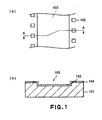
- Figure 1 is a schematic drawing of the ink jet recording head substrate, which has been completed through the step shown in Figure 2(a) to the step shown in Figure 2(c)
- Figure 1(a) is the plan view thereof
- Figure 1(b) is a sectional view thereof at a line A-A in Figure 1(a)
- Each of the drawings in Figures 2 and 3 is a sectional view of the substrate at a line comparable to the line A-A in Figure 1(b) .
- the ink jet recording head manufactured using the ink jet recording head manufacturing method in this embodiment has a substrate 101 on which a plurality of ejection pressure generation elements 102 for generating the pressure for ejecting ink (liquid) were formed.
- the substrate 101 is provided with a recess 103, which is on the obverse surface of the substrate 101, and occupies the area from the opening of the ink supply hole 110 ( Figure 3(d) , etc.) to the area next to where the ejection pressure generation elements 102 are located.
- the plurality of ejection pressure generation elements 102 are disposed at a predetermined pitch in two lines extending in the lengthwise direction of the recess 103, along the two lengthwise edges of the recess 103, one for one.
- the two lines of ejection energy generation elements 102 are offset by half the pitch relative to each other.
- the substrate 101 is also provided with a semiconductor circuit inclusive of transistors and the like for driving the ejection pressure generation elements 102, pads as electrodes for electrically connecting the recording head with the main assembly of a recording apparatus.
- these components are not shown in the drawings, in order to make the drawings easier to understand.
- the bottom surface of the recess 103 is virtually parallel to the surface areas of the substrate 101, across which the ejection pressure generation elements 101 were formed. It has the hole, in the center, created as the hole grown in the substrate by etching the substrate from the reverse side thereof to form the ink supply hole became connected to the bottom of the recess 103. Each of the two areas of the bottom surface of the recess 103 separated by this hole will become the recessed portion of the bottom surface of an ink passage, through the subsequent steps. The surface of this recessed portion and the surface of the ink supply hole 110 form a ridge 111 at where they meet.
- the ink jet recording head is provided with an orifice plate 106 which has a plurality of nozzles, each of which comprises a passage extending from the ink supply hole 110 to the corresponding ejection pressure generation element 102, and an orifice 106, the center of which aligns with that of the corresponding ejection pressure generation element 102 in terms of the direction perpendicular to the surface of the ejection pressure generation element 102.
- the provision of the recess 103 provides an ink supply passage with a bottom surface, a part of which is recessed relative to the surface area of the substrate 101, across which the plurality of ejection pressure generation elements 102 are present. Therefore, even if the OH distance has been reduced to reduce liquid droplet size, the flow resistance between the ink and ink supply passage remains relatively small, making it possible to maintain the recording speed at a relatively higher level.
- On the obverse surface (top surface in drawing), inclusive of the recess 103, of the substrate 101 is covered with the protective layer 104 resistant to the etching process for forming the ink supply hole 110.
- a piece of single crystal silicon wafer, the crystal orientation of the surface of which is ⁇ 100>, is used as the substrate 101.
- a plurality of heat generating resistors as the ejection pressure generation elements 102, the driver circuit (unshown) for driving the heat generating resistors, and the electrical pads (unshown) for exchanging signals between the ink jet recording head and the main assembly of a recording apparatus are formed on the surface of the substrate 101 with the use of one of the widely used semiconductor manufacturing processes ( Figure 2(a) ).
- a layer of resist is formed in a predetermined pattern on the obverse side of the substrate 101.
- the obverse side of the substrate 101 is etched by a reactive ion etching method which uses the above described resist layer as a mask, creating the recess 103 which extends, in terms of the width direction of the recess 103, from the area corresponding in position to the ink supply hole 110 ( Figure 3(c) , etc.), to the immediate adjacencies of the rows of the ejection pressure generation elements 102.
- the resist layer is removed ( Figure 2(b) ).
- silicon nitride (SiN) film as the protective layer 104, is formed across the obverse surface of the substrate 1, in a pattern which covers a predetermined areas ( Figure 2(c) ); the protective layer 104 is patterned to cover the entire surface of the recess 103 so that when the ink supply hole is formed, the ridge 111 ( Figure 13(d)) remains covered.
- SiN silicon nitride
- the obverse surface of the substrate 101 is solvent coated with the polymethyl-isopropenyl-ketone, that is, UV resist, which can be dissolved away later.
- the method used for this process is a spin coating method.
- This resist layer is exposed to UV light, and developed, forming the liquid passage formation pattern 105 ( Figure 3(a) ).
- This negative resist layer is exposed to a photo-mask having a predetermined pattern, and developed, removing thereby the portions of the negative resist layer corresponding in position to the orifices 106 and electrical pads ( Figure 3(b) ).
- the outward surface of the orifice plate, inclusive of the orifices 106, is coated with a nozzle protective resin 108 containing cyclized rubber, in order to protect the nozzle portions.
- the SiN film is formed across the reverse surface of the substrate 101 with the use of a plasma CVD method.
- this SiN film may be formed in advance at the same time as the formation of the protective layer 104 on the obverse surface of the substrate 101, which is shown in Figure 2(c) .
- a resist layer is formed on the SiN film on the reverse surface of the substrate 101, covering the entirety of the reverse surface except for the center area which corresponds to the center portion of the recess 103 on the front side of the substrate 101. Then, the SiN film on the reverse surface of the substrate 101 is removed by dry etching, with this resist layer functioning as a mask. Then, the resist layer is removed. As a result, a reverse surface mask layer 109 is effected, which has a hole corresponding in size and location to the opening of the ink supply hole which will be formed next.
- the reverse surface of the substrate 101 is dipped in to the mixture of nitric acid, hydrofluoric acid, and acetic acid, in order to remove the portion of the substrate 101 corresponding to the ink supply hole 110, through the hole of the reverse surface mask layer 109, using an anisotropic etching method.
- the anisotropic etching process is continued until the hole created by the etching reaches the inward surface of the protective layer 104 of the recess 103 of the substrate 101.
- the ink supply hole 110 is effected ( Figure 3(c) ).
- the portion of the protective layer 104, which has been exposed due to the formation of the ink supply hole 110, is removed by chemical dry etching.
- the nozzle protective resin layer 108 covering the orifice plate, inclusive of the nozzles is removed with xylene.
- the entirety of the substrate 101, inclusive of the elements formed thereon is subjected to ultrasonic waves while being dipped in ethyl lactate. As a result, the UV resist in the pattern of the liquid passage 105 is dissolved away ( Figure 3(d) ).
- the ink jet recording head described above can be formed by a large number at the same time, on a single piece of silicon wafer which constitutes the substrate 101.
- the silicon wafer is diced to separate the large number of the ink jet recording heads after the formation of the ink jet recording heads thereon.
- the protective layer 104 is present on the bottom surface of the recess 103 on the obverse side of the substrate 101. Therefore, the ridge 111 formed by the bottom surface and the surface of the ink supply hole 110 is not exposed to the etchant from the obverse side of the substrate. Therefore, it does not occur that etching speed suddenly increases in the adjacencies of the ridge 111; in other words, the etching process progresses at a constant speed, making it possible to highly precisely forms the ridge 111 virtually true to a predetermined specification.
- the ink jet recording head manufactured through the manufacturing method in this embodiment is provided with ink supply passages, the bottom surface of each of which is provided with a recess portion. Therefore, even though the OH distance of the head has been reduced, the flow resistance between the ink supply passage and the ink therein has not substantially increased, making it possible for the ink passage to be quickly refill with ink. Also in the case of this ink jet recording head, the ridge to be formed by the recess portion of the bottom surface of an ink passage, and the surface of the ink supply hole 110 can be precisely formed virtually true to the desired specification, making it possible to form a plurality of ink supply passages leading to nozzles, uniform in flow resistance. Therefore, all the ink passages can be reliably refilled.
- the surface of the recess 103 is covered with the protective layer 104, being prevented from being corroded by ink.
- this protective layer 104 can be given the function of preventing the portions of the lateral surfaces of the functional layers, for example, the circuit layer for driving the ejection pressure generation elements 102, exposed on recess 103 side, from being corroded by ink.
- providing the bottom wall of the ink passage with the recessed portion resulting from the recess 103 provides the bottom wall with a stepped portion, as shown in Figure 3(d) .
- the stepped portion is thought to offer the following benefit. That is, during the long span of ink jet recording head usage, air or the like sometimes enters an ink jet recording head, forming unwanted bubbles, and these unwanted bubbles are trapped by the stepped portion created by the provision of the recessed portion resulting from the recess 103.
- silicon nitride is used as the material for the protective layer 104.
- a different material resistant to the etchant for forming the ink supply hole 110 may be used in place of the silicon nitride.
- silicon oxide, silicon oxide-nitride, as well as metal such as Ta, Cu, Au, Pt, etc., alloys thereof, or organic substance such as polyamide, polyether-amide, or the like, may be used.
- the protective layer 104 may be formed so that not only does it cover the lateral and bottom walls of the recess 103, but also the ejection pressure generation elements 102 and driving circuit therefor formed on the substrate 101; in other words, the protective layer 104 may be formed to cover the entirety of the obverse side of the substrate 101, inclusive of the elements formed thereon. With such coverage by the protective layer 104 as described above, the ejection pressure generation elements 102 and driving circuit therefor can be prevented from being corroded by ink.
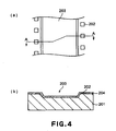
- Figure 4 is a schematic drawing of the ink jet recording head substrate in this embodiment, after the completion of the manufacturing steps from the first step to the step comparable to the step shown in Figure 2(c) ;
- Figure 4(a) is a plan view thereof, and
- Figure 4(b) is a sectional view thereof at the line A-A in Figure 4(a) .
- the recess 203 is formed by an anisotropic etching method. With the use of this etching method, the lateral walls of the recess 203 become slanted.
- the ink jet recording head manufacturing steps in this embodiment other than the step for forming the recess 203 are the same as those in the first embodiment.
- the ink jet recording head manufactured with the use of the ink jet manufacturing method in this embodiment is virtually identical to that manufactured with the use of the method in the first embodiment, except that the lateral walls of the recessed portion of each ink passage, which connect the bottom wall of the recess 203 and the surface area of the substrate, on which the ejection pressure generation elements 202 are formed, are slanted.
- the surface of this recess 203 is covered with the protective layer 204.
- the substrate is precisely etched in order to form the ridge 211 to be formed by the bottom surface of the recess 203 and the surface of the ink supply hole, virtually true to a predetermined specification, but also, to form ink passages, the recessed portion of the bottom surface of which is highly resistant to the corrosiveness of alkaline ink.
- the recess 203 be formed with the use of a chemical method, for example, the anisotropic etching method used in this embodiment, the reactive ion etching method used in the first embodiment, wet etching method, chemical dry etching method, but also a physical method such as laser processing method, or a mechanical method such as drilling or end milling may be used.
- a chemical method for example, the anisotropic etching method used in this embodiment, the reactive ion etching method used in the first embodiment, wet etching method, chemical dry etching method, but also a physical method such as laser processing method, or a mechanical method such as drilling or end milling may be used.
- the protective layer 204 can be used to seal therein the debris resulting from the formation of the recess 203, in particular, the debris generated when the substrate 201 is etched with the mechanical process to form the recess 203. Confining the debris such as those described above prevents the debris from flowing with ink during recording head usage, preventing thereby the nozzles from being plugged up by the debris.
- Figure 5 is a schematic drawing of the ink jet recording head substrate in this embodiment, after the completion of the manufacturing steps from the first step to the step comparable to the step in the first embodiment shown in Figure 2(c) ;
- Figure 5(a) is a plan view thereof, and
- Figure 5(b) is a sectional view thereof at the line A-A in Figure 5(a) .
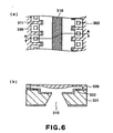
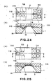
- Figure 6 is a schematic drawing of the completed ink jet recording head;
- Figure 6(a) is a horizontal sectional view thereof, and
- Figure 6(b) is the vertical sectional view thereof at the plane A-A in Figure 6(a) .
- the recess 303 in this embodiment has a plurality of rectangular appendages extending toward the ejection pressure generation elements, one for one.
- the remaining portion of the obverse surface of the substrate is shaped so that it has a plurality of appendages extending between the adjacent two appendages of the recess 303, one for one, toward the ink supply hole 310, from between the adjacent two ejection pressure generation elements aligned at a predetermined pitch.
- a recess such as the recess 303 in this embodiment can be formed by removing the portion of the substrate corresponding to the recess 303, with the use of a reactive ion etching method after forming a resist layer on the obverse surface of the substrate 301, in the above described pattern.
- the orifice plate 306 is formed so that the liquid passage walls 311 which are integral parts of the orifice plate 306, extend toward the ink supply hole 310, to the virtual ends, one for one, of the above described appendage portions of the obverse surface of the substrate, which extend toward the ink supply hole from between the adjacent two ejection pressure generation elements aligned at a predetermined pitch.
- the manufacturing steps in this embodiment can be carried out as those in the first embodiment, except that in this embodiment, the ink supply hole 310 is formed by anisotropic etching which uses water solution of TMAH.
- the recess 303 has a plurality of rectangular appendages, which extend to the immediate adjacencies of ejection pressure generation elements 302, one for one, not only effectively reducing the flow resistance of the ink supply passage, but also, making the liquid passage walls 311 long enough to effectively prevent the so-called cross talk, that is, the phenomenon that the ink ejection pressure generated in a given nozzle propagates to adjacent nozzles.
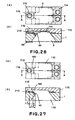
- Figure 7 is a schematic drawing of the ink jet recording head substrate in this embodiment, after the completion of the manufacturing process from the first step to the step comparable to the step in the first embodiment shown in Figure 2(c) ;
- Figure 7(a) is a plan view thereof, and
- Figure 7(b) is a vertical sectional view thereof at the line A-A in Figure 7(a) .
- the protective layer 404 is left to cover only the surface of the recess 403.
- the manufacturing steps in this embodiment other than the step for leaving the protective layer 404 in the pattern described above can be carried out as those in the first embodiment.
- the formation of the protective layer 404 make it possible to precisely etch the substrate so that the ridge 111 to be formed by the bottom surface of the recess 405 and the surface of the ink supply hole, is highly precisely formed virtually true to a predetermined specification, but also to make the recess 403 highly resistant to the corrosiveness of the alkaline ink.
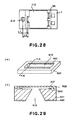
- Figure 8 is a schematic sectional view of the ink jet recording head in this embodiment, sequentially showing the ink jet recording manufacturing method in this embodiment from the first step to the step comparable to the step in the first embodiment shown in Figure 2(c) .
- a piece of single-crystal silicon wafer, the crystal orientation of the surface of which is ⁇ 100> is prepared as a substrate, that is, the substrate 501, and the recess 503 is formed ( Figure 8(b) ) in the obverse surface of the substrate 501, by removing the portion of the substrate 501, from the area corresponding to the ink supply hole to the adjacencies of the areas across which the ejection pressure generation elements 502 are to be formed, as in the case of the first embodiment.
- the driving circuit for the ejection pressure generation elements 502 are formed on the obverse surface of the substrate 501.
- SiO film which is electrically insulating, is formed as one of the functional layers of the driving circuit, in a predetermined pattern, with the use of a plasma CVD method, across the area inclusive of the recess 503.
- This SiO film is used as the protective layer 504, which is comparable in function to the protective layers in the first to fourth embodiments ( Figure 8(c) ).
- this protective layer 405 improves the level of preciseness with which the ridge 111 is formed by the surface of the ink supply hole and the bottom surface of the recess 503, by preventing the etchant from bleeding onto the obverse side of the substrate 501 while etching the substrate 501 from the reverse side to form the ink supply hole in a subsequent step. Further, the presence of this protective layer 504 makes the walls of the recess 503, that is, the recessed portion of the bottom surface of the ink passage, highly resistant to the corrosiveness of ink.
- the protective layer 504 can be formed at the same time as one or more of the functional layers of the driving circuit are formed on the substrate 501, making it possible to improve manufacturing efficiency.
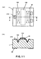
- Figures 9 - 17 are schematic drawings of the ink jet recording head in this reference example, showing the ink jet recording heads after the completion of the manufacturing steps, one for one, in the order in which the steps are carried out.
- (a) is a plan view of the ink jet recording head in this embodiment
- (b) is a vertical sectional view thereof at the line A-A in the plan view (a).
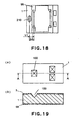
- Figure 18 is a plan view of the completed ink jet recording head shown in Figure 17 .
- the nozzle layer is not shown.
- the ink jet recording head manufactured with the use of the ink jet recording head manufacturing method in this reference example has a substrate 1, on which a plurality of heaters (electro-thermal transducer elements) 210, as ejection pressure generation elements, for heating the ink (liquid) to generate ink (liquid) ejection pressure by generating bubbles in the ink (liquid) were formed.
- a substrate 1 on which a plurality of heaters (electro-thermal transducer elements) 210, as ejection pressure generation elements, for heating the ink (liquid) to generate ink (liquid) ejection pressure by generating bubbles in the ink (liquid) were formed.
- the semiconductor circuit inclusive of transistors or the like, for driving the heaters 210, electrical pads for maintaining electrical connection between the recording head and the main assembly of a recording apparatus, they are not shown in order to make the drawings easier to understand.
- the substrate 1 is provided with an ink supply hole 110, which is a through hole.
- the heaters 110 are disposed in two lines along the edges of the ink supply hole 110, on the obverse side of the substrate. Although only three heaters 210 are shown in the drawings in order to make it easier to understand the drawings, the ink jet recording head manufacturing method in this reference example can manufacture an ink jet recording head having a much larger number of heaters 210. These heaters 210 are disposed in two straight lines, one line on each side of the ink supply hole 110, at a predetermined pitch. In terms of the direction in which the heaters 210 are aligned, the heaters 210 on one side of the ink supply hole 110 are offset by half the pitch from those on the other side.
- the nozzle layer 115 having a plurality of the nozzles.
- Each nozzle has an ink passages 107 and an orifice 116.
- the ink passage extends from the ink supply hole 110 over the heaters 210, and the orifice 116 opens at the obverse surface of the substrate 1 and is correspondent in position to one of the heaters 210.
- a silicon wafer the crystal orientation index of which is ⁇ 100>, is used as the substrate 1.
- SiNx film which functions as the obverse surface etching mask layer 2 and reverse surface etching mask 99 shown in Figure 9 , are formed to a thickness of 100 nm on the obverse and reverse surface of the substrate 1.
- a photo-resist layer is formed in a predetermined pattern on the silicon nitride film on the obverse surface of the substrate 1 with the use of a photolithographic process.
- the silicon nitride film is etched by a reactive ion etching method which uses CF 4 gas, with this photo-resist layer used as a mask.
- the photo-resist layer is peeled away, effecting thereby on the obverse surface of the substrate 1, the surface etching mask layer 2 having a pair of elongated openings as shown in Figure 9(a) .
- the pair of elongated openings are on the ink supply hole 110 side of the areas, across which two lines of heaters 210 will be formed in one of the subsequent steps, and extend in the direction of the two lines.
- the substrate 1 is etched by an anisotropic etching method with the surface etching mask 2 used as a mask, effecting thereby two grooves 100 in the obverse surface of the substrate 1.
- TMAH TMAH was used at 83°C in temperature, and 22% in concentration. The rate of etching is 0.68 ⁇ m/min.
- heaters 210 were formed in two lines, each line of the heaters 210 being on the outward side of the corresponding groove 100, as shown in Figure 10 .
- a sacrificial layer 120 is formed in the form of a rectangle which extends between the two grooves 100, in the direction of the two grooves 100, a predetermined distance beyond the lines of the heaters 210.
- the sacrificial layer 120 is formed of a substance dissolvable when creating the ink supply hole 110 by etching.
- polysilicon polycrystalline silicon
- the polysilicon film was formed as the sacrificial layer 120 across a predetermined area, in the predetermined pattern, with the use of one of the photolithographic technologies.
- the thickness of the sacrificial layer 120 was 3,000 ⁇ .
- SiOx film is formed on the surface of the substrate 1 on the obverse side, and then, a protective film (passivation film) 95 is formed by patterning as shown in Figure 11 .
- the protective film 95 covered the internal surfaces of each groove 100, and the top and lateral surfaces of the sacrificial layer 120.
- the SiNx film formed on the surface of the substrate 1 on the reverse side, that is, the obverse surface etching mask 99 was given by patterning, a hole with a predetermined size, which directly opposes the sacrificial layer 120 across the substrate 1.
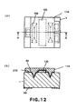
- an ink passage formation layer 114 was formed as shown in Figure 12 , which would be removed by etching in one of the subsequent steps to create the ink passages 107 ( Figure 17 ).
- the ink passage formation layer 114 comprised the center portion which covered the sacrificial layer 120 and the pair of grooves 100, and a plurality of appendages which extend from the center portion over the heaters 210, one for one, with the presence of a predetermined interval between the adjacent two appendages.
- a resin is used as the material for the ink passage formation layer 114, the depth and opening size of each groove 100 to be formed in the obverse surface of the substrate 1 can be adjusted to reduce the effect of the presence of the groove 100 upon the thickness of the ink passage formation layer 114, in order to improve the distribution of the thickness in which the ink passage formation layer 114 is formed.
- a nozzle formation layer 115 was formed on the liquid passage formation layer 114 as shown in Figure 13 . Then, the orifices 116 were made through the nozzle formation layer 115, in alignment with the heaters 210, one for one. Incidentally, the orifices 116 can be formed with the use of one of the photolithographic technologies, or the like.
- the substrate 1 was etched from the reverse side by the anisotropic etching method with the reverse surface etching mask layer 99 used as a mask, effecting thereby the groove 5 in the reverse side of the substrate 1 as shown in Figure 14 .
- the obverse and lateral sides of the substrate 1 are covered with a resinous substance such as a cyclized rubber or the like, in order to protect the nozzle formation layer 115.
- TMAH TMAH was used at 22% in concentration of and 83°C in temperature.
- the sacrificial layer 120 was easily etched through this etching process, whereas the protective layer 95 formed of SiO was resistant to this etching process, and was not etched, remaining thereby intact.
- the area of the SiOx film layer on the reverse surface of the substrate 1, which was to be removed to form the opening of the reverse surface etching mask 99, and the area of the obverse surface of the substrate 1, on which the sacrificial layer 120 was to be formed, were adjusted in position so that the opening of the groove 5, on the obverse side of the substrate 1, coincided with the bottom surface of the sacrificial layer 120, or was within the range of the sacrificial layer 120, as shown in Figure 14(b) , when forming the groove 5 by etching the substrate 1 from the reverse side.
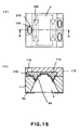
- the anisotropic etching process was continued to grow the groove 5 deeper and wider until the groove 5 reached the wall of each of the grooves 100 as shown in Figure 15 .
- the protective layer 95 was exposed from the reverse side of the substrate 1, across the areas corresponding to the inward wall of each groove 100 and the area corresponding to the sacrificial layer 120.
- the protective layer 95 that is, the film of SiOx was etched away, across the area exposed from the reverse side of the substrate 1, with the use of buffered hydrofluoric acid.
- the ink passage layer 114 is dissolved away as shown in Figure 17 . If the obverse and lateral sides of the substrate 1 were covered with a resinous substance such as a cyclized rubber or the like in order to protect the nozzle formation layer 115 as described above, this resinous substance is desired to be removed prior to the dissolving of the nozzle formation layer 115 in order to successfully and effectively remove the ink passage formation layer 114.
- a resinous substance such as a cyclized rubber or the like
- the grooves 100 which had been formed from the obverse side of the substrate 1 become fully connected to the groove 5 which had been formed from the reverse side of the substrate 1, effecting thereby the ink supply hole 110, as well as the ink passages 107 which extend to the ejection orifices 116, one for one, from the ink supply hole 110.
- the two grooves 100 whose side surfaces were inclined and which had been formed by anisotropic etching were destroyed, leaving only the portions of the protective layer 95 corresponding, one for one, to the outward surfaces of the two grooves 100.
- the position of the edges of the ink supply hole 110, on the obverse side of the substrate 1 is determined by the position of the outward edges of the two grooves 100 formed from the obverse side of the substrate 1.
- the two grooves 100 are formed from the obverse side of the substrate 1, that is, the same side of the substrate 1 as the surface of the substrate 1, on which the heaters 210 are formed. Therefore, the grooves 100 can be accurately positioned relative to the heaters 210. Therefore, the ink supply hole 110 can be accurately positioned, with ease, relative to the heaters 210.
- the obverse surface of the substrate 1 is where the semiconductor circuit is formed.
- the grooves 100 in this reference example formed in this surface were highly accurate in position and dimension, because the smaller the number of crystalline defects on a given surface, the higher the level of accuracy at which the grooves 100 can be easily formed in the given surface.
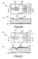
- the grooves 100 can be formed so that their edges, in other words, the edges of the opening of the ink supply hole 110, on the obverse side of the substrate 1, will be very accurately positioned relative to the substrate 1. Therefore, the distance L1 ( Figures 17 and 18 ) between the edge of the ink supply hole 110 and the center of a given heater 210 becomes very accurate.
- the size of the opening of the through hole, on the obverse side of the substrate sometimes becomes different from the predetermined one due to the crystalline defects of the substrate, deviation in the substrate thickness and orientation flat angle, deviation in the etching liquid concentration, high temperature process in some of the semiconductor manufacturing steps, etc.
- the distance between the through hole, that is, the ink supply hole, and each of the ejection pressure generation elements (which hereinafter will be referred to as CH distance) is different from a predetermined one, which makes the plurality of ejection nozzles nonuniform in one of their characteristics, that is, the refilling of the nozzles with ink, more specifically, the delivery of ink to an ejection energy generation element.
- the nonuniformity in the refilling of an ink ejection nozzle with ink significantly affects the operational characteristics, in particular, the operational frequency, of an ink jet recording head. More specifically, the longer the CH distance of a nozzle, the slower the refilling of the nozzle, being therefore lower in the operational frequency, that is, the frequency at which a nozzle is refilled with ink for the next ejection. Therefore, the operational frequency of an ink jet recording head must be adjusted to the frequency at which a nozzle which is greater in CH distance, and therefore, lower in operational frequency, can successfully operate; in other words, it must be restricted to a relatively lower frequency.
- the edge of the opening of the groove 5, on the obverse side of the substrate 1 falls within the range of the sacrificial layer 120. More specifically, the edge of the opening of the groove 5, on the obverse side of the substrate 1, which grows with the progress of the etching, coincides with the borderline between the area of the substrate 1, on the obverse side of the substrate 1, across which the sacrificial layer 120 easily dissolvable by etching was formed, and the area of the substrate 1, across which the corrosion resistant protective film 95 was formed.
- the sacrificial layer 120 functions to suppress, more specifically, compensate for, the effects of the deviation in the etching speed, preventing thereby the problems that the contour of the portion of the substrate 1 being etched for the formation of the groove 5 deviates from a straight line, or that an ink jet head manufacturing operation becomes inconsistent in the location at which the edge of the through hole being etched for the formation of the groove 5 will be located after a given length of time from the beginning of the etching process, during an ink jet recording manufacturing process.
- the growth of the groove 5 connects the groove 5 to the grooves 100 in the last stage of this step.
- the groove 5 becomes connected to the grooves 100 virtually at the same time across the entirety of its edges, because the effects of the fluctuation in the etching speed are suppressed by the function of the sacrificial layer 120 as described above.
- Each of the internal surfaces of the ink supply hole 110 effected by the merger between the groove 5 and grooves 100, parallel to the lines of the heaters 210, is slanted so that the distance between the two internal surfaces of the ink supply hole 110 is smallest between the ridge between the groove 5 and one of the grooves 100, and the ridge between the groove 5 and another groove 100.
- the ink jet recording head manufacturing method in this reference example makes it possible to highly precisely form the ridge portions between the groove 5 and grooves 100 of an ink jet recording head, which are effected by the merger between the groove 5 and grooves 100.
- the distance L2 ( Figures 14 and 10 ) from this ridge to the center of a given heater 210 becomes highly accurate, minimizing the difference among the nozzles in terms of the distance L2.
- the ink jet recording head manufacturing method in this reference example makes it possible to highly precisely form the ink supply passages which extend to the ink passages 107, one for one, from the ink supply hole 110, to a predetermined specification, minimizing thereby the difference among the nozzles, in other words, making the nozzles uniform in terms of the conductance of the liquid supply passage from the ink supply hole 110 to a nozzle, which in turn makes it possible to eject ink at a higher frequency, making it therefore possible to record at a higher speed.
- the ink jet recording head manufacturing method in this reference example can manufacture an ink jet recording head capable of recording at a higher speed.
- ink jet recording heads manufactured through the trial runs of the manufacturing method in this reference example ink could be satisfactorily ejected through all nozzles at an ejection frequency of 25 kHz, proving that they were higher than 25 kHz in terms of the upper limit of the ejection frequency.
- the area of the ink supply passage on the obverse side of the ridge effected between the groove 5 formed from the reverse side of the substrate 1 and grooves 100 formed from the obverse side of the substrate 1, as the groove 5 merges with the grooves 100, are covered with the protective layer 95, being therefore less likely to be corroded by ink, compared to the area on the obverse side of the ridge of an ink jet recording head manufactured with the use of one of the ink jet recording head manufacturing methods in accordance with the prior arts.
- the groove 5 is formed by anisotropic etching.
- the surfaces of the groove 5 have a crystal orientation index of ⁇ 111>, being therefore highly resistant to alkaline.
- the ink supply passages of the ink jet recording head manufactured by the manufacturing method in this reference example are highly corrosion resistant to ink. Therefore, even if a corrosive ink, for example, alkaline ink, is used, virtually no silicon dissolves into the ink. In fact, when the ink left for a predetermined length of time in the ink jet recording heads manufactured through the trial runs of the manufacturing method in this reference example was analyzed, silicon and the like could not be detected at a significant level; they had not dissolved into the ink by a significant amount.
- the internal surface of each of the grooves 100 formed from the obverse side of the substrate 1 is entirely covered with the protective film 95 after the formation of the grooves 100. Therefore, even if the grooves 100 are formed by isotropic wet etching, or anisotropic or isotropic dry etching, the grooves 100 are highly corrosion resistant to ink. Further, the protective film 95 can be given such a function as to protect the semiconductor circuit and the like formed on the obverse surface of the substrate 1.
- the protective film 95 is formed on the obverse side of the substrate 1 prior to the formation of the groove 5 by etching the substrate 1 from the reverse side of the substrate 1. Therefore, when the groove 5 is formed, the etching liquid does not come into contact with the obverse surface of the substrate 1, on which the semiconductor circuit is present; in other words, the anisotropic etching for forming the groove 5 can be carried out without adversely affecting the semiconductor circuit and the like.
- the above described ink jet recording head manufacturing method in this reference example is much smaller in the amount of the debris generated during the formation of the ink supply hole, compared to the ink jet head manufacturing methods in which ink supply hole is formed by sand blasting, laser processing, or the like.
- this reference example can manufacture an ink jet recording head which is highly resistant to the corrosiveness of ink, and whose nozzles are uniform in ink refill properties.
- this reference example can manufacture an ink jet recording head in which ink is reliably supplied to all nozzles by a predetermined precise amount.
- a piece of silicon wafer, the crystal orientation index of the surface of which was ⁇ 100> was used as the substrate 1.
- a piece of silicon wafer, the crystal orientation index of the surface of which is ⁇ 110> may be used as the substrate 1.
- a groove having internal surfaces with a crystal orientation index of ⁇ 111> that is, internal surfaces highly resistant to the corrosiveness of ink, can be formed from the reverse side of the substrate 1 by anisotropic etching.
- the formation of the groove 5 from the reverse side of the substrate 1 may be carried out by one of the wet etching methods which is not anisotropic.
- the ridge can be highly precisely formed true to a predetermined shape and dimension, between the grooves 100 formed from the obverse side of the substrate 1 and the groove 5 formed from the reverse side of the substrate 1.
- the grooves 100 were formed from the obverse side of the substrate 1 by the anisotropic etching.
- the grooves 100 may be formed by isotropic wet etching, isotropic dry etching, or anisotropic dry etching.
- the protective film 95 should be formed to cover the internal surfaces of the grooves as described above, so that the grooves 100 become highly resistant to the corrosiveness of ink.
- SiNx film was formed as the revers surface etching mask 99.
- SiOx film may be formed.
- the sacrificial layer 120 polycrystalline silicon film was formed.
- film, other than the polycrystalline silicon film, that can be easily dissolved by the wet etching process for forming the groove 5, may be formed.
- the sacrificial layer 120 may be formed of aluminum.
- SiOx film is formed as the protective film 95.
- a film, other than the SiOx film, that is resistant to the corrosiveness of highly alkaline chemicals, in particular, KOH and TMAH, which are used for anisotropic etching, may be used.
- a SiNx film may be formed as the protective film 95.
- both the SiOx film and SiNx film may be formed.
- film formed of polyether-amide, or the like, can be used as the protective film 95.
- Figures 19 - 27 are schematic drawings of the ink jet recording head in this reference example, showing the ink jet recording heads after the completion of the manufacturing steps, one for one, in the order in which the steps are carried out.
- (a) is a plan view of the ink jet recording head in this reference example
- (b) is a vertical sectional view thereof at the line A-A in the plan view (a).
- Figure 28 is a plan view of the completed ink jet recording head shown in Figure 27 .
- the nozzle layer is not shown.
- the ink jet recording head manufactured with the use of the ink jet recording head manufacturing method in this reference example has a substrate 1 provided with an ink supply hole 110, which is a through hole, and a plurality of heaters 210 disposed in two lines along the top edges of the ink supply hole 110, one line for each edge.
- a nozzle formation layer 115 having a plurality of the nozzles, each of which has an ejection orifice 116 positioned directly above a heater, and an ink passage 160 leading from the ink supply hole 110 to the ejection orifice 116.
- each ink passage 160 is shaped so that the portion of its bottom surface, on the ink supply hole 110 side, is slanted downward; in other words, the portion of the bottom surface of the ink passage 160, on the ink supply hole 110 side, is sloped downward toward the ink supply hole 110; in other words, it has a recessed portion.
- the size (diameter) in which ink droplets are ejected is reduced by shortening the OH distance, without substantially reducing the ejection orifice size, or while leaving the ejection orifice size as is.
- this measure not only is it possible to make it less likely for ejection orifices to be plugged up by debris, but also, to reduce the flow resistance in the ink passage extending from a heater to the corresponding ejection orifice, reducing thereby the amount of pressure required to eject ink, which in turn makes it possible to reduce heater capacity. With the reduction of heater capacity, the head temperature remains lower, reducing thereby the amount by which the water in the ink evaporates.
- each ink passage 160 is shaped so that the portion of its bottom surface, on the ink supply hole 110 side, is tilted downward toward the ink supply hole 110, reducing thereby the flow resistance in the ink passage 160.
- the flow resistance in the ink passage 160 has been reduced without reducing the length of the ink passage 160, making less likely to occur the so-called cross-talk, that is, the phenomenon that the pressure generated in a given nozzle by a 210 for ink ejection adversely affects the ink ejection from other nozzles, by vibrating the ink in the other nozzles.
- a silicon wafer the crystal orientation index of which is ⁇ 100>, is used as the substrate 1.
- SiNx film which functions as the obverse surface etching mask layer 3 and reverse surface etching mask 99 shown in Figure 19 , is formed to a thickness of 100 nm on the obverse and reverse surfaces of the substrate 1.
- a photo-resist layer is formed in a predetermined pattern on the SiNx film on the obverse surface of the substrate 1 with the use of a photolithographic process.
- the SiNx film is etched by a reactive ion etching method which uses CF 4 gas, with this photo-resist layer used as a mask.
- the photo-resist layer is peeled away, effecting thereby on the obverse surface of the substrate 1, the surface etching mask layer 3 having a predetermined pattern.
- the surface etching mask layer 3 had a plurality of openings, as shown in Figure 19(a) , which coincided in position with the bottom surfaces of the ink passages 160 ( Figure 28 ), which would be formed later.
- a plurality of short grooves 100 were formed in the obverse surface of the substrate 1 by anisotropic etching, with this surface etching mask layer 3 used as a mask.
- this surface etching mask layer 3 used as a mask.
- TMAH was used as the etching liquid, at 83°C in temperature and 22% in concentration.
- the rate of etching was 0.68 ⁇ m/min.
- heaters 210 were formed on the obverse surface of the substrate 1, one for each groove 101, on the opposite side of the groove 100, with respect to the area which corresponded in position to an ink supply hole 110 ( Figure 27 ) which would be formed later.
- a sacrificial layer 120 was formed on the obverse surface of the substrate 1, on the rectangular area between the two rows of grooves 100, which were on the inward side of the two strips of areas in which two rows of nozzles would be formed one for one.
- the sacrificial layer 120 was formed so that it extended a predetermined distance beyond both lengthwise ends of the rows of the heaters 210.
- polysilicon film (polycrystalline silicon film) was used as the sacrificial layer 120; the sacrificial layer 120 was formed in a predetermined pattern on a predetermined area of the obverse surface of the substrate 1 using one of the photolithographic technologies.
- the thickness of the sacrificial layer 120 was 3,000 ⁇ .
- SiOx film was formed on the surface of the substrate 1 on the obverse side, and then, a protective film (passivation film) 95 was formed by patterning as shown in Figure 21 .
- the protective film 95 covered the internal surfaces of each groove 100, and the top and lateral surfaces of the sacrificial layer 120.
- the SiNx film formed by deposition on the surface of the substrate 1, on the reverse side was formed by patterning into a reverse surface etching mask 99, which had a hole with a predetermined size, which directly opposed the sacrificial layer 120 across the substrate 1.
- an ink passages formation layer 114 was formed as shown in Figure 22 , which would be removed by etching, in one of the subsequent steps, to create the ink passages 160 ( Figure 27 ).
- the ink passage formation layer 114 comprised the center portion which covered the sacrificial layer 120 and a plurality of appendages which extend from the center portion over the heaters 210, one for one, with the presence of a predetermined interval between the adjacent two appendages. The base of each appendage was located closer to the center of the sacrificial layer 120 than the corresponding groove 100.
- each groove 100 was located between the theoretical walls of the corresponding ink passage 160, which would be formed later; it was located so that it would become a part of the bottom surface of the ink passage 160.
- the depth of each groove 100 was made the same as that of the groove 100 in the second reference example.
- the size of the opening of the groove 100 was smaller than that of the groove 100. Therefore, when resin was coated to form the ink passage formation layer 114, it could be more easily and uniformly coated than when resin was coated to form the ink passage layer 114 in the sixth embodiment.
- a nozzle formation layer 115 was formed on the liquid passage formation layer 114 as shown in Figure 23 . Then, the orifices 116 were made through the nozzle formation layer 115, in alignment with the heaters 210, one for one.
- the substrate 1 was etched from the reverse side by the anisotropic etching method with the reverse surface etching mask layer 99 used as a mask, effecting thereby the groove 5 in the reverse side of the substrate 1 as shown in Figure 24 .
- the obverse and lateral sides of the substrate 1 are covered with a resinous substance such as a cyclized rubber or the like, in order to protect the nozzle formation layer 115.
- TMAH TMAH was used at 22% in concentration and 83°C in temperature.
- the sacrificial layer 120 was easily dissolved away through this etching process, whereas the protective layer 95 formed of SiO was resistant to this etching process, and was not etched, remaining therefore intact.
- the anisotropic etching process was continued to grow the groove 5 until the groove 5 reached each of the grooves 100 on the obverse side of the substrate 1, as shown in Figure 25 . More specifically, the groove 5 was grown until the protective layer 95 was exposed from the reverse side of the substrate 1, across the areas corresponding to the inward wall of each groove 100.
- the protective layer 95 that is, the film of SiOx
- the protective layer 95 was etched away, as shown in Figure 27 , with the use of buffered hydrofluoric acid, across the area exposed from the reverse side of the substrate 1 due to the formation of the groove 5.
- the ink passage layer 114 was dissolved away as shown in Figure 27 . If the obverse and lateral sides of the substrate 1 had been covered with a resinous substance such as a cyclized rubber or the like in order to protect the nozzle formation layer 115 as described above, this resinous substance is desired to be removed prior to the dissolving of the nozzle formation layer 115, in order to successfully and effectively remove the ink passage formation layer 114.
- a resinous substance such as a cyclized rubber or the like
- the grooves 100 which had been formed from the obverse side of the substrate 1 merged with the groove 5 which had been formed from the reverse side of the substrate 1, effecting thereby the ink supply hole 110, as well as the ink passages 160 which extend to the ejection orifices 116, one for one, from the ink supply hole 110.
- the outward wall of each groove 100 formed in the first step on the substrate 1, on the obverse side still remained, making the portion of the bottom surface of each ink passage 160, next to the ink supply hole 110, slope downward toward the ink supply hole 110.
- this portion of the bottom surface of each ink passage 160 was covered with the protective film 95, and sloped downward to the opening of the ink supply hole 110, on the obverse side of the substrate 1. Thus, a ridge was formed between this portion of the bottom surface of each ink passage 160 and the surface of the ink supply hole 110.
- the position of the edges of the ink supply hole 110, on the obverse side of the substrate 1 is determined by the position of the outward edges of the grooves 100 formed from the obverse side of the substrate 1.
- the grooves 100 are formed from the obverse side of the substrate 1, that is, the same side of the substrate 1 as the surface of the substrate 1 on which the heaters 210 are formed. Therefore, the grooves 100 can be accurately positioned relative to the heaters 210 arranged in a predetermined pattern. Therefore, the ink supply hole 110 can be accurately positioned, with ease, relative to the heaters 210.
- the obverse surface of the substrate 1 is where the semiconductor circuit is formed.
- the grooves 100 in this reference example formed in this surface are highly accurate in position and dimension.
- the grooves 100 can be formed so that their inward edges, in other words, the inward edges of the opening of the ink supply hole 110, on the obverse side of the substrate 1, parallel to the rows of heaters 210, will be very accurately positioned relative to the substrate 1. Therefore, the distance L1' ( Figures 27 and 28 ) between the edge, on the obverse side of the substrate 1, of the sloped portion of the bottom surface of each ink passage 160, and the center of a given heater 210 becomes very accurate.
- the groove 5 was formed from the reverse side of the substrate 1 by etching, so that the edge of the opening of the groove 5, on the obverse side of the substrate 1, fell within the range of the sacrificial layer 120. Therefore, when the groove 5 was formed, the problems that the above described ridge between a given ink passage 160 and the ink supply hole 110 become misaligned due to the crystalline defects of the substrate, deviation in the thickness and orientation flat angle of the substrate 1, deviation in the etching liquid concentration, high temperature process in some of the semiconductor manufacturing steps, etc., was suppressed, that is, compensated for, by the sacrificial layer 120. Therefore, as the groove 5 was formed, all grooves 100 merged with the groove 5 all at once.
- the protective layer 95 extends to the ridge between the groove 100 and the groove 5. Therefore, the phenomenon that the ridge is disfigured due to the increase in etching rate does not occur. Therefore, the ridge between the ink supply hole 9 and each of the ink passages 160 can be highly accurately formed virtually true to a predetermined specification. Therefore, it is possible to make accurate the distance L2' between the ridge between the ink supply hole 110 and a given ink passage 160 ( Figures 27 and 28 ). Further, each ink passage 160 can be highly accurately formed, in particular, the portion of the ink passage 160, on the ink supply hole 110 side, virtually true to the predetermined specification.
- the ink jet recording head manufacturing method in this reference example makes it possible to highly accurately remove the portions of the substrate 1, which correspond in position to the portion of the ink passages 160, on the ink supply hole 110 side. Therefore, the ink passages 160 are accurately and uniformly formed, being therefore uniform in ink conductance. Further, the end portion of each ink passage 160, on the ink supply hole 110 side, is provided with the downwardly sloped bottom surface. With the provision of this structural arrangement, even if the OH distance is reduced, the flow resistance of the ink passage 160 does not increase, because the increase in flow resistance, which would have occurred due to the reduction in the OH distance, is cancelled by the provision of this structural arrangement. Therefore, ink can be ejected at a higher frequency.
- the ink jet recording head manufacturing method in this reference example can manufacture an ink jet recording head capable of recording at a higher speed.
- ink jet recording heads manufactured through trial runs of the manufacturing method in this reference example were tested, ink could be satisfactorily ejected through all nozzles at an ejection frequency of 60 kHz, proving that they were higher than 60 kHz, in the upper limit of the ejection frequency.
- the ridge between the bottom surface of each ink passage 160 and the surface of the ink supply hole 110 could be highly accurately formed, preventing thereby the occurrence of the cross-talk.
- the nozzle pitch of which was 600 dpi nozzle interval of 42.5 ⁇ m
- the downwardly sloped portion of the bottom surface of each ink passage 160 that is, the portion of the bottom surface of each ink passage, immediately next to the ridge between the bottom surface of the ink passage and the surface of the ink supply hole 110 is covered with the protective film 95, and the surfaces of the ink supply hole 110 formed by anisotropic etching has a crystal orientation index of ⁇ 111>. Therefore, this ridge between the bottom surface of the ink passage 160 and the surface of the ink supply hole 110 is highly resistant to the corrosiveness of ink, even if alkaline ink is used. Further, the sloped portion of the bottom surface of each ink passage 160 is covered with the protective film 95, being therefore highly resistant to ink.
- this reference example makes it possible to manufacture an ink jet recording head which is highly resistant to the corrosiveness of ink. If fact, when the ink left for a predetermined length of time in the ink jet recording heads manufactured through the test runs of the manufacturing method in this reference example was analyzed, silicon and the like could not be detected at a significant level; they had not dissolved into the ink by a significant amount.
- the internal surface of each of the grooves 100 formed from the obverse side of the substrate 1 is entirely covered with the protective film 95 after the formation of the grooves 100. Therefore, even if the grooves 100 are formed by isotropic wet etching, or anisotropic or isotropic dry etching, the grooves 100 are highly resistant to the corrosiveness of ink. Further, the protective film 95 can be given such a function as to protect the semiconductor circuit and the like formed on the obverse surface of the substrate 1.
- the protective film 95 is formed on the obverse side of the substrate 1 before the groove 5 is formed by etching the substrate 1 from the reverse side of the substrate 1. Therefore, when the groove 5 is formed, the etching liquid does not come into contact with the obverse surface of the substrate 1, on which the semiconductor circuit is present; in other words, the anisotropic etching for forming the groove 5 can be carried out without adversely affecting the semiconductor circuit and the like.
- the above described ink jet recording head manufacturing method in this reference example is much smaller in the amount of the debris generated during the formation of the ink supply hole, compared to the ink jet head manufacturing methods in which ink supply hole is formed by sand blasting, laser processing, or the like.
- this reference example could manufacture an ink jet recording head which was highly resistant to the corrosiveness of ink, and whose nozzles are uniform in ink refill properties.
- this reference example could manufacture an ink jet recording head in which ink was reliably supplied to all nozzles by a predetermined precise amount.
- a piece of silicon wafer, the crystal orientation index of the surface of which is ⁇ 110> may be used as the substrate 1, in place of the piece of silicon wafer, the crystal orientation index of the surface of which is ⁇ 100>.
- the method for forming the groove 5 from the reverse side of the substrate 1 may be one of the wet etching methods which are not anisotropic.
- SiOx film may be formed instead of the SiNx film.
- the sacrificial layer 120 film, other than the polycrystalline silicon film, may be formed.
- the sacrificial layer 120 may be formed of aluminum.
- the protective film 95 SiOx film, SiNx film, two-layer film comprising SiOx film and SiNx film, polyether-amide film, etc., may be used.
Description
- The present invention relates to an ink jet recording head and a manufacturing method therefor.
- Generally, an ink jet recording head used for an ink jet recording method (liquid ejection recording method) comprises: a plurality of minute holes (which hereinafter will be referred to as orifices ) from which liquid (ink) is ejected; a plurality of liquid passages leading to the plurality of orifices; and a plurality of ejection pressure generating portions disposed in the liquid passages to generate the pressure for ink ejection. In order to produce high quality images with the use of this type of ink jet recording head, it is desired that the plurality of orifices are uniform, and remain consistent, in the volume by which ink is ejected from an orifice, and the speed at which ink is ejected from an orifice. One of the recording methods capable of achieving this objective is disclosed in
Japanese Laid-open Patent Application 4-10940 - In the case of this recording method, the volume by which ink is ejected in the form of an ink droplet is mostly determined by the area size of the orifice, and the distance between the ejection pressure generation element and orifice (which hereinafter will be referred to as "OH distance"). Thus, in the case of an ink jet recording head for this type of recording method, it is desired to reduce the OH distance as much as possible in order to reduce the ink droplet size as much as possible so that an image can be recorded at as high a level of resolution as possible. Further, in order to assure that ink is ejected in the form of an ink droplet, the volume of which is true to a predetermined specification, an ink jet recording head must be accurately formed to make the OH distance true to the predetermined specification.
- One of the ink jet recording head manufacturing methods capable of making the OH distance true to the predetermined specification is disclosed in
Japanese Patent 3143307
Then, ejection orifices are created through this layer. Lastly, the dissolvable resin layer is dissolved away. -
Figure 29 is a schematic drawing of one of the ink jet recording heads produced following the above described steps;Figure 29(a) is a perspective view of the ink jet recording head, theorifice plate 606 of which formed of the above described wall formation layer has been removed, andFigure 29(b) is an enlarged sectional view of the ink jet recording head, at a line A-A inFigure 29(a) . - This ink jet recording head has a
substrate 601 on the obverse surface of which a plurality of ejectionpressure generation elements 602 are present. Thesubstrate 601 has a through hole formed, as anink supply hole 610, through thesubstrate 601, by etching thesubstrate 601 from the reverse side, with the reversesurface masking layer 609 used as a mask. The plurality of ejectionpressure generation elements 602 are arranged in two rows, at a predetermine pitch, along the lengthwise edges of the opening of theink supply hole 610, on the obverse side of thesubstrate 601, one for each edge. This ink jet recording head is of the so-called side shooter type. Therefore, theorifices 607 of theorifice plate 606 formed on thesubstrate 601 are disposed directly opposite to the top surface of the ejectionpressure generation elements 602, one for one. - Further, not only are the ink jet recording apparatuses such as the above described one required to have higher resolution and higher quality, but also higher throughput, in other words, higher ejection frequency (driving frequency). In order to raise ejection frequency, it is necessary to increase the refill speed, that is, the speed at which ink passages are refilled with ink after ink ejection. In order to increase refill speed, it is desired to reduce the flow resistance of an ink passage from an ink supply hole to an orifice.
- In the past, therefore, in order to increase ink refill speed, measures have been taken to place an ink supply hole, from which ink flows into each ink passage, as close as possible to an ejection pressure generation element. More specifically, measures have been taken to reduce an ink passage in length as well as height. However, there was a limit to the level of accuracy at which an ink supply hole could be formed. Also, in order to assure that a plurality of ink passages properly and harmoniously work, it was necessary to prevent the so-called cross-talk, that is, the phenomenon that ink ejection becomes unstable due to the propagation of the pressure generated when ejecting ink, among the plurality of nozzles. In other words, the measure of reducing the length of an ink passage had a limit of its own. Therefore, the employment of this measure was not an ultimate solution to the problem.
- There is disclosed in
Japanese Laid-open Patent Application 6-238904 - There is disclosed in
Japanese Laid-open Patent Applications 10-34928 10-95119 -
Japanese Laid-open Patent Application 6-238904 - Besides, even if an anisotropic etching method is used to form the two grooves from the obverse and reverse sides, one for one, in order to make the surfaces of the two grooves highly resistant to the corrosiveness of alkaline, more specifically, to form the two grooves so that their surfaces will have a crystal orientation index of <111>, the ridge created as the groove formed from the obverse side of the substrate merges with the groove formed from the reverse side, does not become resistant to the corrosiveness of alkaline ink, even through the surfaces of the two grooves have the crystal orientation index of <111>. Moreover, the rate at which this ridge resulting from the merging of the two surfaces with the crystal orientation index of <111> is etched by an anisotropic etching method is higher than the rate at which the two surfaces with the crystal orientation index of <111> are etched by an anisotropic etching. Therefore, it is very difficult to form this ridge true to a predetermined pattern. This problem is not limited to an anisotropic etching method. That is, even if a wet etching method is employed, the ridge resulting from the angular merging of the two surfaces is likely to be etched at a higher rate than the other portion of the substrate, making it very difficult to give the ridge the predetermined configuration.
- Further, although
Japanese Laid-open Patent Applications 10-34928 10-95119 Japanese Laid-open Patent Application 10-34928 - Further, in the case of the methods in which after a recess is formed in the obverse surface of a substrate, the member for forming nozzles, ejection pressure generation elements, semiconductor circuit, such as the circuit for driving the ejection pressure generation elements, etc., are formed, and then, an ink supply hole is formed from the reverse side of the substrate, it is necessary to prevent the nozzle formation member, semiconductor circuit, etc., from being damaged in the step in which the ink supply hole is formed. This makes impractical the usage of most of the anisotropic etching methods, which are capable of highly precisely processing the substrate for an ink jet recording head, but use highly alkaline chemicals, for example, KOH (potassium hydroxide), and TMAH (tetramethyl ammonium hydroxide). On the other hand, if sand blasting, laser etching, or the like, is used to form an ink supply hole, debris is generated, which raises the concern that the debris might plug the nozzles of an ink jet recording head, in particular, when forming an ink jet recording head having the extremely minute nozzles required in recent years.
-
US 5,729,261 discloses a thermal ink jet printhead with improved resistance to corrosive effects of ink by coating the surface of a photo-imageable polymer with an ink resistant film. - An object of the present invention is to provide an ink jet recording head, in which the height of each of the ink passages is higher in the adjacencies of the ink supply hole than in the adjacencies of the ejection pressure generation element; the edge of the ink supply hole, on the obverse side of the substrate, from which each ink passage extends, is true in configuration to a predetermined specification; and even the subordinate recess immediately next to the edge of the ink supply hole, on the obverse side of the substrate, is highly resistant to the corrosiveness of ink, an ink jet recording head manufacturing method for forming said ink jet recording head, and a substrate for said ink jet recording head.
- In the present invention , an ink jet recording head according to
claim 1 is provided for accomplishing the above described object. - Further, the recess may be formed in the area of the surface of the substrate, on which ejection pressure generation elements are present, so that a plurality of portions of the recess extend from the edges of the ink supply hole toward the area on which the ejection pressure generation elements are present. In this case, the liquid passage walls, which separate a given liquid passage from the adjacent liquid passages, may be extended on the area of the surface of the substrate, on which the ejection pressure generation elements are present, more specifically, the intervals between the adjacent two ejection pressure generation elements, and the intervals between the adjacent two subordinate recesses extended toward the ejection pressure generation elements, one for one, from the primary recess (
Figure 6(a) ). With the employment of this structural arrangement, that is, by extending the subordinate recesses to the adjacencies of the ejection pressure generation elements, not only can the ink passages be substantially reduced in flow resistance, but also, they can be increased in length enough to effectively prevent the problems that ink ejection becomes unstable due to the propagation of the pressure generated for ink ejection, among the nozzles. - The protective layer is formed so that the ejection pressure generation elements and the driving circuit therefor are covered in order to make the protective layer to prevent these components from being corroded by ink.
- Further, the protective layer may be shared by one or more of the functional layers of the driving circuit for the ejection pressure generation elements. With such an arrangement, the protective layer can be more efficiently formed.
- As the material for the protective layer, it is possible to think of various substances resistant to the wet etching for forming an ink supply hole, for example, silicon nitride, silicon oxide, silicon oxide-nitride, metallic substances such as Ta, Cu, Au, Pt, etc., alloys thereof, organic substances such as polyamide, polyether-amide, etc.
- According to another aspect of the present invention, a manufacturing method for manufacturing an ink jet recording head in accordance with the present invention is provided in claim 10.
- In the case of the above described ink jet recording head manufacturing method, as a groove to become the supply post may be formed by wet etching through a substrate from the reverse side in order to form an ink supply hole, ridges are formed by the surfaces of the groove and the bottom surface of the recess. Since the bottom surface of the recess is covered with the protective layer, it does not occur that the etching speed increases at these ridges; in other words, the etching speed remains constant even at the ridges. Therefore, the ridges do not deviate in configuration. In other words, this ink jet recording head manufacturing method can precisely form these ridges virtually true to a desired specification.
- Also in the case of the above described ink jet recording head manufacturing method, the bottom surface of the recessed portion of each ink passage from the ink supply hole to an ink nozzle, which results from the formation of the recess, may be covered with the protective film. Therefore, the ridge formed by the bottom surface of the recessed portion of each ink passage, and the surface of the ink supply hole, is highly resistant to the corrosiveness of ink. Further, if the functional layers for the driving circuit for the ejection pressure generation elements are exposed at the lateral surfaces of the recessed portion of the ink passage, this protective layer may be given the function of protecting the exposed portions of the functional layers from being corroded by ink.
- Also in the case of the ink jet recording head manufacturing method in accordance with the present invention, a dry etching method such as chemical dry etching, reactive ion etching, etc., a wet etching method such as anisotropic etching, a physical etching method such as laser processing, or a mechanical etching method such as drilling, end-milling, etc., can be used to form the recess. In any case, the protective layer is formed on the surface of the recess. Therefore, the surfaces of the recessed portion of each ink passage, resulting from the provision of the recess, is highly resistant to the corrosiveness of ink. Further, it is thought that the debris generated when the recess is formed, in particular, when a mechanical process is used to form the recess, can be confined by, or in, the protective layer to prevent the problem that while a recording head is in use, the debris is flowed with ink, and plugs the nozzles.
- Also in the case of the ink jet recording head manufacturing method in accordance with the present invention, the etching method used for etching a substrate from the reverse side thereof may be an isotropic etching method which uses nitric acid, mixture of acids, or the like, an anisotropic etching method which uses alkaline solution such as water solution of KOH or TMAH, or the like chemical etching methods.
- Further, the ink jet recording head manufacturing method may comprise a step for forming an orifice plate having orifices and liquid passages, on the surface of a substrate, on the side on which ejection pressure generation elements were formed. The orifice plate may be formed through the following steps: a step in which photosensitive resin is solvent coated, and the coated photosensitive resin is given a predetermined pattern by a photolithographic technology; and a step in which a liquid passage formation member having a liquid passage formation pattern is formed of dissolvable resin, and is covered with resin which will become the orifice plate; and a step in which the liquid passage formation member is dissolved away.
- According to another aspect the areas immediately next to the edge of the ink supply hole, on the obverse side of the substrate, may be recessed from the area of the obverse surface of the substrate, on which the ejection pressure generation elements are present, and the protective layer covers a minimum of the surface of this recessed area.
- According to another aspect, the for for ink jet recording head may comprise: an ink supply hole through which liquid is a substrate having the plurality of ejection pressure generation elements, and a groove(s) formed in the area of the surface of the substrate, which is located next to the theoretical line corresponding in position to the edge(s) of the opening of the ink supply hole which will be formed later; a sacrificial layer, which was formed on the portion of the surface of the substrate, which is next to the groove and corresponds in position to the theoretical center of the ink supply hole to be formed later, and which will be dissolved away by wet etching to form the ink supply hole; a protective layer formed on the surface of the groove and resistant to the wet etching process for forming the ink supply hole; a passivation layer formed to cover the sacrificial layer and resistant to the wet etching process for forming the ink supply hole; an etching mask layer formed on the reverse surface of the substrate, that is, the surface opposite to the surface on which the plurality of ejection pressure generation elements are present, to form the ink supply hole, and having an opening which defines the area of the reverse surface of the substrate, from which the wet etching process for forming the ink supply hole is to be started so that as the groove started from the reverse side of the substrate by the wet etching process for forming the ink supply hole grows, the inward edge, that is, the edge on the obverse side of the substrate, of the groove eventually falls within the range of the sacrificial layer.
- In the case of an ink jet recording head manufacturing method which uses the above described ink jet recording head substrate, a first groove may be formed from the reverse side of this ink jet recording head substrate, by wet etching, with the etching mask layer used as a mask. The wet etching process is continued until the end of the first groove, on the obverse side of the substrate, fully grows into the sacrificial layer and eliminates it. Then, the portion of the protective layer exposed by the growth of the first groove is removed. As a result, the first groove becomes connected to the groove(s) formed in the surface of the substrate, on which the ejection pressure generation elements are present, completing thereby the ink supply hole.
- During this process of forming the ink supply hole, the groove formed in the substrate by wet etching from the reverse side of the substrate grows past the borderline between the sacrificial layer and passivation layer. While the groove is growing in the adjacencies of the borderline, the edge of the opening of the groove, on the obverse side of the substrate, comes into contact with the borderline, being thereby straightened. In other words, even if the edge of the opening of the groove, on the obverse side of the substrate, grows slightly irregular due to the misalignment between the substrate and etching mask in terms of the relationship between the etching mask pattern and the crystal orientation of the substrate, and also, due to the deviation in the thickness of the silicon wafer, the irregularities of the edge are rectified while the groove is growing past the borderline. After being rectified at the borderline between the sacrificial layer and passivation film, the edge of the opening of the groove, on the obverse side of the substrate, expands wider, reaching thereby the groove(s) formed in the substrate from the obverse side of the substrate. As a result, a ridge(s) is formed by the portion of the protective layer, which, at this stage, constitutes the inward wall of the groove formed from the obverse side of the substrate, and the surface of the groove formed from the reverse side of the substrate. Since the ridge is between the above described portion of the protective layer and the surface of the groove formed from the reverse side of the substrate, the etching speed does not accelerate at the ridge; in other words, the etching progresses at a stable rate across the etching front. As will be evident from the above description, using an ink jet recording head substrate in accordance with the present invention makes it possible to highly precisely form the ink supply hole, so that the internal ridge of which between the groove formed from the obverse side of the substrate and the groove formed from the reverse side of the substrate becomes virtually true in configuration to a predetermined specification. Therefore, it is possible to afford a greater amount of latitude in designing the structure of the ink supply hole, and its adjacencies.
- Further, in the case of the ink jet recording head manufacturing method which employs the ink jet recording head substrate in accordance with the present invention, the edge of the ink supply hole, on the obverse side of the substrate, results from the edge of the groove formed from the obverse side of the substrate. Therefore, using this ink jet recording head manufacturing method makes it possible to exactly position the edge of the ink supply hole, on the obverse side of the substrate, relative to the other structural components, for example, the ejection pressure generation elements which are present on the surface of the substrate, on the obverse side, since the edge of the groove formed from the obverse side can be positioned directly relative to these structural components.
- As will be evident from the above description, using the ink jet recording head substrate in accordance with the present invention makes it possible to manufacture an ink jet recording head, the nozzles of which are uniform in ink passage conductance, and are quickly and reliably refilled.
- Further, the recess portion, immediately next to the edge of the ink supply hole, formed by forming a groove from the obverse side of the substrate, is covered with the protective film. Therefore, it is highly resistant to the corrosiveness of ink. Further, an anisotropic etching method, which creates a groove with a surface having a crystal orientation index of <111>, which is higher in the resistance to the corrosiveness of alkalies, is used as the etching method for forming the groove from the reverse side of the substrate. Therefore, the surface of the ink supply hole is highly resistant to the corrosiveness of ink. In other words, using the ink jet recording head substrate in accordance with the present invention makes it possible to manufacture an ink jet recording head, the entirety of which is highly resistant to the corrosiveness of ink.
- The groove(s) to be formed in the obverse surface of the ink jet recording head substrate in accordance with the present invention may be in the form of a single(or two) relatively long groove(s) which extends in the adjacencies of a plurality of rows of ejection pressure generation elements, in parallel to the rows of ejection pressure generation elements, or in the form of a plurality of short grooves, provided one for each ejection pressure generation element, and aligned in two rows parallel to the rows of ejection pressure generation elements. In the case of the latter, the walls which separate adjacent two ink passages can be extended into the areas between the adjacent two short grooves; in other words, the walls can be extended to prevent the occurrence of the cross-talk.
- Further, the protective film and passivation film may be formed so that they are in contact with each other, with no gap between them, in the adjacencies of the opening of the ink supply hole, on the obverse side of the substrate. With the provision of this structural arrangement, the etching liquid is prevented from seeping onto the obverse side of the substrate, when wet etching the substrate from the reverse side. Therefore, even if the substrate is etched from the reverse side after the formation of the semiconductor circuit layer and nozzle formation layer on the obverse surface of the substrate, these layers are not adversely affected by the etching liquid. Also, instead of a processing method, such as sand blasting or laser etching, which generates debris, which causes nozzle blockage, a highly precise processing method, such as anisotropic etching method, can be used to form the groove from the reverse side of the substrate.
- As the protective film or passivation film, inorganic film, such as SiO film and SiNx film, or laminar film comprising SiOx film and SiNx film, can be used. The protective film and passivation film may be formed of polyether-amide. The sacrificial layer can be formed of polycrystalline silicon film or aluminum. As the etching mask layer, SiOx film and SiNx film can be used. As the substrate, a wafer, the crystal orientation index of which is <100> or 110, can be used. Using such a wafer as the substrate makes it possible to form, in the substrate, a groove, the surface of which is highly resistant to the corrosiveness of alkalies, from the reverse side of the substrate by anisotropic etching.
- In the case of an ink jet recording head manufactured with the use of an ink jet recording head substrate in accordance with the present invention, the area(s) immediately next to the edge(s) of the ink supply hole is recessed. Therefore, even if the OH distance is reduced, the liquid passages remain relatively low in flow resistance, remaining therefore relatively fast in refilling speed. In other words, an ink jet recording head substrate in accordance with the present invention is suitable for forming an ink jet recording head, which employs electro-thermal transducers as ejection pressure generation elements, is required to be short in the OH distance to record highly precise images, and is required to be quickly refilled to record at a high speed.
- The ink jet recording head in accordance with the present invention can be manufactured using an ink jet recording head substrate such as the above described one. According to another aspect of the present invention, an ink jet recording head can be formed such that the surface of the area(s) between each ink passage, and the edge of the opening of the ink supply hole, on the obverse side of the substrate, is sloped downward toward the edge, and this area is covered with the protective film resistant to the wet etching process for forming the ink supply hole.
- The ink jet recording head manufacturing method in accordance with the present invention may use an ink jet recording head substrate such as the above described one. According to another aspect of the present invention, an ink jet recording head manufacturing method may comprise: a step for forming a first groove in a substrate; a step for forming a plurality of ejection pressure generation elements as ejection pressure generation portions, next to the first groove; a step for forming a sacrificial layer dissolvable by the wet etching process for forming the ink supply hole, on the opposite side of the first groove from the side on which the ejection pressure generation elements are present; a step for forming on the surface of the first groove, a protective layer resistant to the wet etching process for forming the ink supply hole; a step for forming a passivation film resistant to the wet etching process for forming the ink supply hole, to cover the sacrificial layer; a step for forming an etching mask layer, on the opposite surface of the substrate from the surface on which the ejection pressure generation elements are present; a step for forming in the substrate, a second groove, which reaches the passivation film and protective film, by wet etching the substrate from the reverse side, that is, the side opposite to the side on which the ejection pressure generation elements are present, with the etching mask used as a mask; and a step for removing the portion of the protective layer exposed by the formation of the second groove to connect the second groove to the first groove formed from the obverse side of the substrate, in order to complete the ink supply hole.
- These and other objects, features, and advantages of the present invention will become more apparent upon consideration of the following description of the preferred embodiments of the present invention, taken in conjunction with the accompanying drawings.
- In the subsequent description, Reference Examples 1 to 3 are outside the scope of the invention as claimed.
-
-
Figure 1 is a schematic drawing of the substrate of the ink jet recording head in the first embodiment of the present invention;Figure 1(a) is a plan view thereof, andFigure 1(b) is a schematic sectional view thereof, at a line A-A inFigure 1(a) . -
Figure 2 is a schematic sectional view of the ink jet recording head in the first embodiment of the present invention, sequentially showing the ink jet recording head manufacturing steps. -
Figure 3 is a schematic drawing of the ink jet recording head in the first embodiment of the present invention, showing the ink jet recording head manufacturing steps subsequent to the steps shown inFigure 2 . -
Figure 4 is a schematic drawing of the substrate of the ink jet recording head in the second embodiment of the present invention;Figure 4(a) is a plan view thereof, andFigure 4(b) is a schematic sectional view thereof, at a line A-A inFigure 4(a) . -
Figure 5 is a schematic drawing of the substrate of the ink jet recording head in the third embodiment of the present invention;Figure 5(a) is a plan view thereof, andFigure 5(b) is a schematic sectional view thereof, at a line A-A inFigure 5(a) . -
Figure 6 is a schematic drawing of the substrate of the ink jet recording head in the third embodiment of the present invention;Figure 6(a) is a horizontal sectional view thereof, andFigure 6(b) is a schematic sectional view thereof, at a line A-A inFigure 6(a) . -
Figure 7 is a schematic drawing of the substrate of the ink jet recording head in the first reference example;Figure 7(a) is a plan view thereof, andFigure 7(b) is a schematic sectional view thereof, at a line A-A inFigure 7(a) . -
Figure 8 is a schematic sectional view of the ink jet recording head in the fourth embodiment of the present invention, sequentially showing the ink jet recording head manufacturing steps. -
Figure 9 is a schematic drawing of the ink jet recording head in the second reference example, showing one of the ink jet recording head manufacturing steps;Figure 9(a) is a plan view thereof, andFigure 9(b) is a sectional view thereof at a line A-A inFigure 9(a) . -
Figure 10 is a schematic drawing of the ink jet recording head in the second reference example, showing the ink jet recording head manufacturing step immediately subsequent to the step shown inFigure 9 ;Figure 10(a) is a plan view thereof, andFigure 10(b) is a sectional view thereof at a line A-A inFigure 10(a) . -
Figure 11 is a schematic drawing of the ink jet recording head in the second reference example, showing the ink jet recording head manufacturing step immediately subsequent to the step shown infigure 10 ;Figure 11(a) is a plan view thereof, andFigure 11(b) is a sectional view thereof at a line A-A inFigure 11(a) . -
Figure 12 is a schematic drawing of the ink jet recording head in the second reference example, showing the ink jet recording head manufacturing step immediately subsequent to the step shown inFigure 11 ;Figure 12(a) is a plan view thereof, andFigure 12(b) is a sectional view thereof at a line A-A inFigure 12(a) . -
Figure 13 is a schematic drawing of the ink jet recording head in the second reference example, showing the ink jet recording head manufacturing step immediately subsequent to the step shown inFigure 12 ;Figure 13(a) is a plan view thereof, andFigure 13(b) is a sectional view thereof at a line A-A inFigure 13(a) . -
Figure 14 is a schematic drawing of the ink jet recording head in the second reference example, showing the ink jet recording head manufacturing step immediately subsequent to the step shown inFigure 13 ;Figure 14(a) is a plan view thereof, andFigure 14(b) is a sectional view thereof at a line A-A inFigure 14(a) . -
Figure 15 is a schematic drawing of the ink jet recording head in the second reference example, showing the ink jet recording head manufacturing step immediately subsequent to the step shown inFigure 14 ;Figure 15(a) is a plan view thereof, andFigure 15(b) is a sectional view thereof at a line A-A inFigure 15(a) . -
Figure 16 is a schematic drawing of the ink jet recording head in the second reference example, showing the ink jet recording head manufacturing step immediately subsequent to the step shown inFigure 15 ;Figure 16(a) is a plan view thereof, andFigure 16(b) is a sectional view thereof at a line A-A inFigure 16(a) . -
Figure 17 is a schematic drawing of the ink jet recording head in the second reference example, showing the ink jet recording head manufacturing step immediately subsequent to the step shown inFigure 16 ;Figure 17(a) is a plan view thereof, andFigure 17(b) is a sectional view thereof at a line A-A inFigure 17(a) . -
Figure 18 is a schematic plan view of the ink jet recording head in the second reference example, without showing the nozzle layer, which has been completed through the steps shown inFigures 9 - 17 . -
Figure 19 is a schematic drawing of the ink jet recording head in the third reference example, showing one of the ink jet recording head manufacturing steps;Figure 19(a) is a plan view thereof, andFigure 19(b) is a sectional view thereof at a line A-A inFigure 19(a) . -
Figure 20 is a schematic drawing of the ink jet recording head in the third reference example, showing the ink jet recording head manufacturing step immediately subsequent to the step shown inFigure 19 ;Figure 20(a) is a plan view thereof, andFigure 20(b) is a sectional view thereof at a line A-A inFigure 20(a) . -
Figure 21 is a schematic drawing of the ink jet recording head in the third reference example, showing the ink jet recording head manufacturing step immediately subsequent to the step shown infigure 20; Figure 21(a) is a plan view thereof, andFigure 21(b) is a sectional view thereof at a line A-A inFigure 21(a) . -
Figure 22 is a schematic drawing of the ink jet recording head in the third reference example, showing the ink jet recording head manufacturing step immediately subsequent to the step shown inFigure 21 ;Figure 22(a) is a plan view thereof, andFigure 22(b) is a sectional view thereof at a line A-A inFigure 22(a) . -
Figure 23 is a schematic drawing of the ink jet recording head in the third reference example, showing the ink jet recording head manufacturing step immediately subsequent to the step shown inFigure 22; Figure 23(a) is a plan view thereof, andFigure 23(b) is a sectional view thereof at a line A-A inFigure 23(a) . -
Figure 24 is a schematic drawing of the ink jet recording head in the third reference example, showing the ink jet recording head manufacturing step immediately subsequent to the step shown inFigure 23 ;Figure 24(a) is a plan view thereof, andFigure 24(b) is a sectional view thereof at a line A-A inFigure 24(a) . -
Figure 25 is a schematic drawing of the ink jet recording head in the third reference example, showing the ink jet recording head manufacturing step immediately subsequent to the step shown inFigure 24; Figure 25(a) is a plan view thereof, andFigure 25(b) is a sectional view thereof at a line A-A inFigure 25(a) . -
Figure 26 is a schematic drawing of the ink jet recording head in the third reference example, showing the ink jet recording head manufacturing step immediately subsequent to the step shown inFigure 25 ;Figure 26(a) is a plan view thereof, andFigure 26(b) is a sectional view thereof at a line A-A inFigure 26(a) . -
Figure 27 is a schematic drawing of the ink jet recording head in the third reference example, showing the ink jet recording head manufacturing step immediately subsequent to the step shown inFigure 26; Figure 27(a) is a plan view thereof, andFigure 27(b) is a sectional view thereof at a line A-A inFigure 27(a) . -
Figure 28 is a schematic plan view of the ink jet recording head in the third reference example, without showing the nozzle layer, which has been completed through the steps shown inFigures 19 - 27 . -
Figure 29 is a schematic drawing of one of the ink jet recording heads in accordance with the prior arts;Figure 29(a) is a perspective view of the ink jet recording head, without showing the orifice plate, andFigure 29(b) is a sectional view thereof, at a line A-A inFigure 29(a) . - Hereinafter, the preferred embodiments of the present invention, as well as reference examples outside the scope of the invention as claimed will be described with reference to the appended drawings.
- Referring to
Figures 1 - 3 , the ink jet recording head manufacturing method in the first embodiment of the present invention will be described.Figures 2 and3 are schematic drawings of the ink jet recording head, sequentially showing the ink jet recording head manufacturing steps, andFigure 1 is a schematic drawing of the ink jet recording head substrate, which has been completed through the step shown inFigure 2(a) to the step shown inFigure 2(c) ;Figure 1(a) is the plan view thereof, andFigure 1(b) is a sectional view thereof at a line A-A inFigure 1(a) . Each of the drawings inFigures 2 and3 is a sectional view of the substrate at a line comparable to the line A-A inFigure 1(b) . - Referring to
Figure 1(a) , the ink jet recording head manufactured using the ink jet recording head manufacturing method in this embodiment has asubstrate 101 on which a plurality of ejectionpressure generation elements 102 for generating the pressure for ejecting ink (liquid) were formed. Thesubstrate 101 is provided with arecess 103, which is on the obverse surface of thesubstrate 101, and occupies the area from the opening of the ink supply hole 110 (Figure 3(d) , etc.) to the area next to where the ejectionpressure generation elements 102 are located. The plurality of ejectionpressure generation elements 102 are disposed at a predetermined pitch in two lines extending in the lengthwise direction of therecess 103, along the two lengthwise edges of therecess 103, one for one. The two lines of ejectionenergy generation elements 102 are offset by half the pitch relative to each other. Thesubstrate 101 is also provided with a semiconductor circuit inclusive of transistors and the like for driving the ejectionpressure generation elements 102, pads as electrodes for electrically connecting the recording head with the main assembly of a recording apparatus. However, these components are not shown in the drawings, in order to make the drawings easier to understand. - Referring to
Figure 3(d) , the bottom surface of therecess 103 is virtually parallel to the surface areas of thesubstrate 101, across which the ejectionpressure generation elements 101 were formed. It has the hole, in the center, created as the hole grown in the substrate by etching the substrate from the reverse side thereof to form the ink supply hole became connected to the bottom of therecess 103. Each of the two areas of the bottom surface of therecess 103 separated by this hole will become the recessed portion of the bottom surface of an ink passage, through the subsequent steps. The surface of this recessed portion and the surface of theink supply hole 110 form aridge 111 at where they meet. The ink jet recording head is provided with anorifice plate 106 which has a plurality of nozzles, each of which comprises a passage extending from theink supply hole 110 to the corresponding ejectionpressure generation element 102, and anorifice 106, the center of which aligns with that of the corresponding ejectionpressure generation element 102 in terms of the direction perpendicular to the surface of the ejectionpressure generation element 102. - As described above, in the case of the ink supply passage in the ink jet recording head in this embodiment, the provision of the
recess 103 provides an ink supply passage with a bottom surface, a part of which is recessed relative to the surface area of thesubstrate 101, across which the plurality of ejectionpressure generation elements 102 are present. Therefore, even if the OH distance has been reduced to reduce liquid droplet size, the flow resistance between the ink and ink supply passage remains relatively small, making it possible to maintain the recording speed at a relatively higher level. On the obverse surface (top surface in drawing), inclusive of therecess 103, of thesubstrate 101 is covered with theprotective layer 104 resistant to the etching process for forming theink supply hole 110. - Next, the ink jet recording head manufacturing steps in this embodiment will be sequentially described.
- In this embodiment, a piece of single crystal silicon wafer, the crystal orientation of the surface of which is <100>, is used as the
substrate 101. In the first step, a plurality of heat generating resistors as the ejectionpressure generation elements 102, the driver circuit (unshown) for driving the heat generating resistors, and the electrical pads (unshown) for exchanging signals between the ink jet recording head and the main assembly of a recording apparatus, are formed on the surface of thesubstrate 101 with the use of one of the widely used semiconductor manufacturing processes (Figure 2(a) ). - Next, a layer of resist is formed in a predetermined pattern on the obverse side of the
substrate 101. Then, the obverse side of thesubstrate 101 is etched by a reactive ion etching method which uses the above described resist layer as a mask, creating therecess 103 which extends, in terms of the width direction of therecess 103, from the area corresponding in position to the ink supply hole 110 (Figure 3(c) , etc.), to the immediate adjacencies of the rows of the ejectionpressure generation elements 102. Thereafter, the resist layer is removed (Figure 2(b) ). - Next, silicon nitride (SiN) film, as the
protective layer 104, is formed across the obverse surface of thesubstrate 1, in a pattern which covers a predetermined areas (Figure 2(c) ); theprotective layer 104 is patterned to cover the entire surface of therecess 103 so that when the ink supply hole is formed, the ridge 111 (Figure 13(d)) remains covered. Through the above described steps, the ink jet recording head substrate having the structure which characterizes the present invention is completed (Figure 1 ). - Next, the obverse surface of the
substrate 101 is solvent coated with the polymethyl-isopropenyl-ketone, that is, UV resist, which can be dissolved away later. The method used for this process is a spin coating method. This resist layer is exposed to UV light, and developed, forming the liquid passage formation pattern 105 (Figure 3(a) ). - Next, the entirety of the obverse surface of the
substrate 101, inclusive of the surface of the liquidpassage formation pattern 105, is coated with epoxy resin of a cation polymerization type, which is negative resist, forming anorifice plate 106 which will be formed into the top wall of each ink passage, and the lateral walls between the adjacent two ink passage. This negative resist layer is exposed to a photo-mask having a predetermined pattern, and developed, removing thereby the portions of the negative resist layer corresponding in position to theorifices 106 and electrical pads (Figure 3(b) ). - Next, the outward surface of the orifice plate, inclusive of the
orifices 106, is coated with a nozzleprotective resin 108 containing cyclized rubber, in order to protect the nozzle portions. Then, the SiN film is formed across the reverse surface of thesubstrate 101 with the use of a plasma CVD method. Incidentally, this SiN film may be formed in advance at the same time as the formation of theprotective layer 104 on the obverse surface of thesubstrate 101, which is shown inFigure 2(c) . - Next, a resist layer is formed on the SiN film on the reverse surface of the
substrate 101, covering the entirety of the reverse surface except for the center area which corresponds to the center portion of therecess 103 on the front side of thesubstrate 101. Then, the SiN film on the reverse surface of thesubstrate 101 is removed by dry etching, with this resist layer functioning as a mask. Then, the resist layer is removed. As a result, a reversesurface mask layer 109 is effected, which has a hole corresponding in size and location to the opening of the ink supply hole which will be formed next. - Next, the reverse surface of the
substrate 101 is dipped in to the mixture of nitric acid, hydrofluoric acid, and acetic acid, in order to remove the portion of thesubstrate 101 corresponding to theink supply hole 110, through the hole of the reversesurface mask layer 109, using an anisotropic etching method. The anisotropic etching process is continued until the hole created by the etching reaches the inward surface of theprotective layer 104 of therecess 103 of thesubstrate 101. As a result, theink supply hole 110 is effected (Figure 3(c) ). - Next, the portion of the
protective layer 104, which has been exposed due to the formation of theink supply hole 110, is removed by chemical dry etching. Then, the nozzleprotective resin layer 108 covering the orifice plate, inclusive of the nozzles, is removed with xylene. Thereafter, the entirety of thesubstrate 101, inclusive of the elements formed thereon, is subjected to ultrasonic waves while being dipped in ethyl lactate. As a result, the UV resist in the pattern of theliquid passage 105 is dissolved away (Figure 3(d) ). - Although not shown in the drawings, the ink jet recording head described above can be formed by a large number at the same time, on a single piece of silicon wafer which constitutes the
substrate 101. When a large number of the ink jet recording heads are formed at the same time on a single piece of silicon wafer, the silicon wafer is diced to separate the large number of the ink jet recording heads after the formation of the ink jet recording heads thereon. - In the case of the above described ink jet recording head manufacturing method in this embodiment, when removing the part of the
substrate 101 from the reverse side, by the anisotropic etching method, theprotective layer 104 is present on the bottom surface of therecess 103 on the obverse side of thesubstrate 101. Therefore, theridge 111 formed by the bottom surface and the surface of theink supply hole 110 is not exposed to the etchant from the obverse side of the substrate. Therefore, it does not occur that etching speed suddenly increases in the adjacencies of theridge 111; in other words, the etching process progresses at a constant speed, making it possible to highly precisely forms theridge 111 virtually true to a predetermined specification. - As will be evident from the above explanation, the ink jet recording head manufactured through the manufacturing method in this embodiment is provided with ink supply passages, the bottom surface of each of which is provided with a recess portion. Therefore, even though the OH distance of the head has been reduced, the flow resistance between the ink supply passage and the ink therein has not substantially increased, making it possible for the ink passage to be quickly refill with ink. Also in the case of this ink jet recording head, the ridge to be formed by the recess portion of the bottom surface of an ink passage, and the surface of the
ink supply hole 110 can be precisely formed virtually true to the desired specification, making it possible to form a plurality of ink supply passages leading to nozzles, uniform in flow resistance. Therefore, all the ink passages can be reliably refilled. - Also in the case of this ink jet recording head, the surface of the
recess 103 is covered with theprotective layer 104, being prevented from being corroded by ink. Further, thisprotective layer 104 can be given the function of preventing the portions of the lateral surfaces of the functional layers, for example, the circuit layer for driving the ejectionpressure generation elements 102, exposed onrecess 103 side, from being corroded by ink. - Also in the case of the ink jet recording head manufactured using the manufacturing method in this embodiment, providing the bottom wall of the ink passage with the recessed portion resulting from the
recess 103 provides the bottom wall with a stepped portion, as shown inFigure 3(d) . The stepped portion is thought to offer the following benefit. That is, during the long span of ink jet recording head usage, air or the like sometimes enters an ink jet recording head, forming unwanted bubbles, and these unwanted bubbles are trapped by the stepped portion created by the provision of the recessed portion resulting from therecess 103. The presence of these bubbles in the adjacencies of the ejectionpressure generation elements 102 has sometimes adverse effects on ink ejection; for example, the pressure generated by the ejectionpressure generation elements 102 for ink ejection is absorbed by these unwanted bubbles. In the case of the ink jet recording head manufactured with the use of the ink jet recording head manufacturing method in this embodiment, however, these unwanted bubbles are trapped by the stepped portion of the bottom wall of the ink passage, which is away from the ejectionpressure generation elements 102. Therefore, the above described adverse effects of these unwanted bubbles are minimized. - Incidentally, in this embodiment, silicon nitride is used as the material for the
protective layer 104. However, a different material resistant to the etchant for forming theink supply hole 110 may be used in place of the silicon nitride. For example, silicon oxide, silicon oxide-nitride, as well as metal such as Ta, Cu, Au, Pt, etc., alloys thereof, or organic substance such as polyamide, polyether-amide, or the like, may be used. Further, theprotective layer 104 may be formed so that not only does it cover the lateral and bottom walls of therecess 103, but also the ejectionpressure generation elements 102 and driving circuit therefor formed on thesubstrate 101; in other words, theprotective layer 104 may be formed to cover the entirety of the obverse side of thesubstrate 101, inclusive of the elements formed thereon. With such coverage by theprotective layer 104 as described above, the ejectionpressure generation elements 102 and driving circuit therefor can be prevented from being corroded by ink. - Next, referring to
Figure 4 , the second embodiment of the present invention will be described.Figure 4 is a schematic drawing of the ink jet recording head substrate in this embodiment, after the completion of the manufacturing steps from the first step to the step comparable to the step shown inFigure 2(c) ;Figure 4(a) is a plan view thereof, andFigure 4(b) is a sectional view thereof at the line A-A inFigure 4(a) . - In this embodiment, the
recess 203 is formed by an anisotropic etching method. With the use of this etching method, the lateral walls of therecess 203 become slanted. The ink jet recording head manufacturing steps in this embodiment other than the step for forming therecess 203 are the same as those in the first embodiment. - Therefore, the ink jet recording head manufactured with the use of the ink jet manufacturing method in this embodiment is virtually identical to that manufactured with the use of the method in the first embodiment, except that the lateral walls of the recessed portion of each ink passage, which connect the bottom wall of the
recess 203 and the surface area of the substrate, on which the ejectionpressure generation elements 202 are formed, are slanted. The surface of thisrecess 203 is covered with theprotective layer 204. Therefore, not only it is possible for the substrate to be precisely etched in order to form the ridge 211 to be formed by the bottom surface of therecess 203 and the surface of the ink supply hole, virtually true to a predetermined specification, but also, to form ink passages, the recessed portion of the bottom surface of which is highly resistant to the corrosiveness of alkaline ink. - Incidentally, not only may the
recess 203 be formed with the use of a chemical method, for example, the anisotropic etching method used in this embodiment, the reactive ion etching method used in the first embodiment, wet etching method, chemical dry etching method, but also a physical method such as laser processing method, or a mechanical method such as drilling or end milling may be used. - It is thought that the
protective layer 204 can be used to seal therein the debris resulting from the formation of therecess 203, in particular, the debris generated when thesubstrate 201 is etched with the mechanical process to form therecess 203. Confining the debris such as those described above prevents the debris from flowing with ink during recording head usage, preventing thereby the nozzles from being plugged up by the debris. - Next, referring to
Figures 5 and6 , the third embodiment of the present invention will be described.Figure 5 is a schematic drawing of the ink jet recording head substrate in this embodiment, after the completion of the manufacturing steps from the first step to the step comparable to the step in the first embodiment shown inFigure 2(c) ;Figure 5(a) is a plan view thereof, andFigure 5(b) is a sectional view thereof at the line A-A inFigure 5(a) .Figure 6 is a schematic drawing of the completed ink jet recording head;Figure 6(a) is a horizontal sectional view thereof, andFigure 6(b) is the vertical sectional view thereof at the plane A-A inFigure 6(a) . - Referring to
Figure 5(a) , therecess 303 in this embodiment has a plurality of rectangular appendages extending toward the ejection pressure generation elements, one for one. Thus, after the formation of therecess 303 in the obverse surface of the substrate, the remaining portion of the obverse surface of the substrate is shaped so that it has a plurality of appendages extending between the adjacent two appendages of therecess 303, one for one, toward theink supply hole 310, from between the adjacent two ejection pressure generation elements aligned at a predetermined pitch. A recess such as therecess 303 in this embodiment can be formed by removing the portion of the substrate corresponding to therecess 303, with the use of a reactive ion etching method after forming a resist layer on the obverse surface of thesubstrate 301, in the above described pattern. - Next, referring to
Figure 6(a) , theorifice plate 306 is formed so that theliquid passage walls 311 which are integral parts of theorifice plate 306, extend toward theink supply hole 310, to the virtual ends, one for one, of the above described appendage portions of the obverse surface of the substrate, which extend toward the ink supply hole from between the adjacent two ejection pressure generation elements aligned at a predetermined pitch. - The manufacturing steps in this embodiment can be carried out as those in the first embodiment, except that in this embodiment, the
ink supply hole 310 is formed by anisotropic etching which uses water solution of TMAH. - In the case of this embodiment, the
recess 303 has a plurality of rectangular appendages, which extend to the immediate adjacencies of ejectionpressure generation elements 302, one for one, not only effectively reducing the flow resistance of the ink supply passage, but also, making theliquid passage walls 311 long enough to effectively prevent the so-called cross talk, that is, the phenomenon that the ink ejection pressure generated in a given nozzle propagates to adjacent nozzles. - Next, referring to
Figure 7 , a first reference example will be described.Figure 7 is a schematic drawing of the ink jet recording head substrate in this embodiment, after the completion of the manufacturing process from the first step to the step comparable to the step in the first embodiment shown inFigure 2(c) ;Figure 7(a) is a plan view thereof, andFigure 7(b) is a vertical sectional view thereof at the line A-A inFigure 7(a) . - Referring to
Figure 7(b) , in this reference example, theprotective layer 404 is left to cover only the surface of therecess 403. The manufacturing steps in this embodiment other than the step for leaving theprotective layer 404 in the pattern described above can be carried out as those in the first embodiment. - Also in the case of the structural arrangement in this reference example, not only does the formation of the
protective layer 404 make it possible to precisely etch the substrate so that theridge 111 to be formed by the bottom surface of the recess 405 and the surface of the ink supply hole, is highly precisely formed virtually true to a predetermined specification,, but also to make therecess 403 highly resistant to the corrosiveness of the alkaline ink. - Next, referring to
Figure 8 , the fourth embodiment of the present invention will be described.Figure 8 is a schematic sectional view of the ink jet recording head in this embodiment, sequentially showing the ink jet recording manufacturing method in this embodiment from the first step to the step comparable to the step in the first embodiment shown inFigure 2(c) . - Next, the ink jet recording head manufacturing steps in this embodiment will be described in the order in which they are carried out.
- Also in this embodiment, a piece of single-crystal silicon wafer, the crystal orientation of the surface of which is <100> (
Figure 8(a) ) is prepared as a substrate, that is, thesubstrate 501, and therecess 503 is formed (Figure 8(b) ) in the obverse surface of thesubstrate 501, by removing the portion of thesubstrate 501, from the area corresponding to the ink supply hole to the adjacencies of the areas across which the ejectionpressure generation elements 502 are to be formed, as in the case of the first embodiment. - Next, the driving circuit for the ejection
pressure generation elements 502 are formed on the obverse surface of thesubstrate 501. During this step, SiO film, which is electrically insulating, is formed as one of the functional layers of the driving circuit, in a predetermined pattern, with the use of a plasma CVD method, across the area inclusive of therecess 503. This SiO film is used as theprotective layer 504, which is comparable in function to the protective layers in the first to fourth embodiments (Figure 8(c) ). In other words, this protective layer 405 improves the level of preciseness with which theridge 111 is formed by the surface of the ink supply hole and the bottom surface of therecess 503, by preventing the etchant from bleeding onto the obverse side of thesubstrate 501 while etching thesubstrate 501 from the reverse side to form the ink supply hole in a subsequent step. Further, the presence of thisprotective layer 504 makes the walls of therecess 503, that is, the recessed portion of the bottom surface of the ink passage, highly resistant to the corrosiveness of ink. - After the formation of the driving circuit through the above described steps, the heat generating resistors as the ejection
pressure generation elements 502 are formed (Figure 8(d) ). The steps thereafter in this embodiment are the same as those in the first embodiment, and can be carried out as in the first embodiment. - In the case of this embodiment, the
protective layer 504 can be formed at the same time as one or more of the functional layers of the driving circuit are formed on thesubstrate 501, making it possible to improve manufacturing efficiency. - Referring to
Figures 9 - 18 , the ink jet recording head manufacturing method in this second reference example will be described.Figures 9 - 17 are schematic drawings of the ink jet recording head in this reference example, showing the ink jet recording heads after the completion of the manufacturing steps, one for one, in the order in which the steps are carried out. In each drawing, (a) is a plan view of the ink jet recording head in this embodiment, and (b) is a vertical sectional view thereof at the line A-A in the plan view (a).Figure 18 is a plan view of the completed ink jet recording head shown inFigure 17 . InFigure 18 , the nozzle layer is not shown. - Referring to
Figures 17 and18 , the ink jet recording head manufactured with the use of the ink jet recording head manufacturing method in this reference example has asubstrate 1, on which a plurality of heaters (electro-thermal transducer elements) 210, as ejection pressure generation elements, for heating the ink (liquid) to generate ink (liquid) ejection pressure by generating bubbles in the ink (liquid) were formed. Although there were formed on thesubstrate 1, the semiconductor circuit, inclusive of transistors or the like, for driving theheaters 210, electrical pads for maintaining electrical connection between the recording head and the main assembly of a recording apparatus, they are not shown in order to make the drawings easier to understand. - The
substrate 1 is provided with anink supply hole 110, which is a through hole. Theheaters 110 are disposed in two lines along the edges of theink supply hole 110, on the obverse side of the substrate. Although only threeheaters 210 are shown in the drawings in order to make it easier to understand the drawings, the ink jet recording head manufacturing method in this reference example can manufacture an ink jet recording head having a much larger number ofheaters 210. Theseheaters 210 are disposed in two straight lines, one line on each side of theink supply hole 110, at a predetermined pitch. In terms of the direction in which theheaters 210 are aligned, theheaters 210 on one side of theink supply hole 110 are offset by half the pitch from those on the other side. There is also on thesubstrate 1, thenozzle layer 115 having a plurality of the nozzles. Each nozzle has anink passages 107 and anorifice 116. The ink passage extends from theink supply hole 110 over theheaters 210, and theorifice 116 opens at the obverse surface of thesubstrate 1 and is correspondent in position to one of theheaters 210. - Next, the ink jet recording head manufacturing steps in this reference example will be described in the order in which they are carried out.
- In this reference example, a silicon wafer, the crystal orientation index of which is <100>, is used as the
substrate 1. First, SiNx film, which functions as the obverse surfaceetching mask layer 2 and reversesurface etching mask 99 shown inFigure 9 , are formed to a thickness of 100 nm on the obverse and reverse surface of thesubstrate 1. Then, a photo-resist layer is formed in a predetermined pattern on the silicon nitride film on the obverse surface of thesubstrate 1 with the use of a photolithographic process. Then, the silicon nitride film is etched by a reactive ion etching method which uses CF4 gas, with this photo-resist layer used as a mask. Then, the photo-resist layer is peeled away, effecting thereby on the obverse surface of thesubstrate 1, the surfaceetching mask layer 2 having a pair of elongated openings as shown inFigure 9(a) . The pair of elongated openings are on theink supply hole 110 side of the areas, across which two lines ofheaters 210 will be formed in one of the subsequent steps, and extend in the direction of the two lines. - Next, the
substrate 1 is etched by an anisotropic etching method with thesurface etching mask 2 used as a mask, effecting thereby twogrooves 100 in the obverse surface of thesubstrate 1. As the etching liquid, TMAH was used at 83°C in temperature, and 22% in concentration. The rate of etching is 0.68 µm/min. - Next,
heaters 210 were formed in two lines, each line of theheaters 210 being on the outward side of thecorresponding groove 100, as shown inFigure 10 . Further, asacrificial layer 120 is formed in the form of a rectangle which extends between the twogrooves 100, in the direction of the twogrooves 100, a predetermined distance beyond the lines of theheaters 210. Thesacrificial layer 120 is formed of a substance dissolvable when creating theink supply hole 110 by etching. In this reference example, polysilicon (polycrystalline silicon) was used as the material for thesacrificial layer 120, and the polysilicon film was formed as thesacrificial layer 120 across a predetermined area, in the predetermined pattern, with the use of one of the photolithographic technologies. The thickness of thesacrificial layer 120 was 3,000 Å. - Next, SiOx film is formed on the surface of the
substrate 1 on the obverse side, and then, a protective film (passivation film) 95 is formed by patterning as shown inFigure 11 . Theprotective film 95 covered the internal surfaces of eachgroove 100, and the top and lateral surfaces of thesacrificial layer 120. Further, the SiNx film formed on the surface of thesubstrate 1 on the reverse side, that is, the obversesurface etching mask 99, was given by patterning, a hole with a predetermined size, which directly opposes thesacrificial layer 120 across thesubstrate 1. - Next, in order to form the nozzles, an ink
passage formation layer 114 was formed as shown inFigure 12 , which would be removed by etching in one of the subsequent steps to create the ink passages 107 (Figure 17 ). The inkpassage formation layer 114 comprised the center portion which covered thesacrificial layer 120 and the pair ofgrooves 100, and a plurality of appendages which extend from the center portion over theheaters 210, one for one, with the presence of a predetermined interval between the adjacent two appendages. The interval portions of theink formation layer 104, between the adjacent pairs of the above described appendage portions of the inkpassage formation layer 104 extending from the center portion over theheaters 210, one for one, were eventually turned into the ink passage walls between the adjacent twoink passages 107. Incidentally, if a resin is used as the material for the inkpassage formation layer 114, the depth and opening size of eachgroove 100 to be formed in the obverse surface of thesubstrate 1 can be adjusted to reduce the effect of the presence of thegroove 100 upon the thickness of the inkpassage formation layer 114, in order to improve the distribution of the thickness in which the inkpassage formation layer 114 is formed. - Next, a
nozzle formation layer 115 was formed on the liquidpassage formation layer 114 as shown inFigure 13 . Then, theorifices 116 were made through thenozzle formation layer 115, in alignment with theheaters 210, one for one. Incidentally, theorifices 116 can be formed with the use of one of the photolithographic technologies, or the like. - Next, the
substrate 1 was etched from the reverse side by the anisotropic etching method with the reverse surfaceetching mask layer 99 used as a mask, effecting thereby thegroove 5 in the reverse side of thesubstrate 1 as shown inFigure 14 . Incidentally, it is desired that when forming thegroove 5 by etching thesubstrate 1 from the reverse side with the use of the anisotropic etching method, the obverse and lateral sides of thesubstrate 1 are covered with a resinous substance such as a cyclized rubber or the like, in order to protect thenozzle formation layer 115. As the etching liquid, TMAH was used at 22% in concentration of and 83°C in temperature. Thesacrificial layer 120 was easily etched through this etching process, whereas theprotective layer 95 formed of SiO was resistant to this etching process, and was not etched, remaining thereby intact. - In this reference example, the area of the SiOx film layer on the reverse surface of the
substrate 1, which was to be removed to form the opening of the reversesurface etching mask 99, and the area of the obverse surface of thesubstrate 1, on which thesacrificial layer 120 was to be formed, were adjusted in position so that the opening of thegroove 5, on the obverse side of thesubstrate 1, coincided with the bottom surface of thesacrificial layer 120, or was within the range of thesacrificial layer 120, as shown inFigure 14(b) , when forming thegroove 5 by etching thesubstrate 1 from the reverse side. - Next, the anisotropic etching process was continued to grow the
groove 5 deeper and wider until thegroove 5 reached the wall of each of thegrooves 100 as shown inFigure 15 . In other words, theprotective layer 95 was exposed from the reverse side of thesubstrate 1, across the areas corresponding to the inward wall of eachgroove 100 and the area corresponding to thesacrificial layer 120. - Next, the
protective layer 95, that is, the film of SiOx was etched away, across the area exposed from the reverse side of thesubstrate 1, with the use of buffered hydrofluoric acid. - Lastly, the
ink passage layer 114 is dissolved away as shown inFigure 17 . If the obverse and lateral sides of thesubstrate 1 were covered with a resinous substance such as a cyclized rubber or the like in order to protect thenozzle formation layer 115 as described above, this resinous substance is desired to be removed prior to the dissolving of thenozzle formation layer 115 in order to successfully and effectively remove the inkpassage formation layer 114. - With the removal of the ink
passage formation layer 114 in the final step, thegrooves 100 which had been formed from the obverse side of thesubstrate 1 become fully connected to thegroove 5 which had been formed from the reverse side of thesubstrate 1, effecting thereby theink supply hole 110, as well as theink passages 107 which extend to theejection orifices 116, one for one, from theink supply hole 110. With the removal of theprotective layer 95 across the above described area, and the removal of the inkpassage formation layer 114, the twogrooves 100 whose side surfaces were inclined and which had been formed by anisotropic etching, were destroyed, leaving only the portions of theprotective layer 95 corresponding, one for one, to the outward surfaces of the twogrooves 100. As a result, ridges were formed by the remaining portions of theprotective layer 104, which was slanted, and the surface of theink supply hole 110, which also was slanted. Thus, the area of the hole, on the obverse side of the ridge is covered with theprotective film 95. - According to the above described ink jet recording head manufacturing method in this reference example, the position of the edges of the
ink supply hole 110, on the obverse side of thesubstrate 1, is determined by the position of the outward edges of the twogrooves 100 formed from the obverse side of thesubstrate 1. Further, the twogrooves 100 are formed from the obverse side of thesubstrate 1, that is, the same side of thesubstrate 1 as the surface of thesubstrate 1, on which theheaters 210 are formed. Therefore, thegrooves 100 can be accurately positioned relative to theheaters 210. Therefore, theink supply hole 110 can be accurately positioned, with ease, relative to theheaters 210. In addition, the obverse surface of thesubstrate 1 is where the semiconductor circuit is formed. Therefore, it has only a very small number of crystalline defects. Therefore, thegrooves 100 in this reference example formed in this surface were highly accurate in position and dimension, because the smaller the number of crystalline defects on a given surface, the higher the level of accuracy at which thegrooves 100 can be easily formed in the given surface. As will be evident from the above description, according to the ink jet recording head manufacturing method in this embodiment, thegrooves 100 can be formed so that their edges, in other words, the edges of the opening of theink supply hole 110, on the obverse side of thesubstrate 1, will be very accurately positioned relative to thesubstrate 1. Therefore, the distance L1 (Figures 17 and18 ) between the edge of theink supply hole 110 and the center of a givenheater 210 becomes very accurate. - Incidentally, when forming a through hole in a substrate from the reverse side thereof with the use of an anisotropic etching method as in this reference example, the size of the opening of the through hole, on the obverse side of the substrate, sometimes becomes different from the predetermined one due to the crystalline defects of the substrate, deviation in the substrate thickness and orientation flat angle, deviation in the etching liquid concentration, high temperature process in some of the semiconductor manufacturing steps, etc. If the deviation in the size of the opening of the through hole created as the ink supply hole, on the obverse side of the substrate, happens to be in the direction perpendicular to the direction in which nozzles extend, the distance between the through hole, that is, the ink supply hole, and each of the ejection pressure generation elements (which hereinafter will be referred to as CH distance) is different from a predetermined one, which makes the plurality of ejection nozzles nonuniform in one of their characteristics, that is, the refilling of the nozzles with ink, more specifically, the delivery of ink to an ejection energy generation element. The nonuniformity in the refilling of an ink ejection nozzle with ink, such as the above described one, significantly affects the operational characteristics, in particular, the operational frequency, of an ink jet recording head. More specifically, the longer the CH distance of a nozzle, the slower the refilling of the nozzle, being therefore lower in the operational frequency, that is, the frequency at which a nozzle is refilled with ink for the next ejection. Therefore, the operational frequency of an ink jet recording head must be adjusted to the frequency at which a nozzle which is greater in CH distance, and therefore, lower in operational frequency, can successfully operate; in other words, it must be restricted to a relatively lower frequency.
- In comparison, in the case of the ink jet recording head manufacturing method in this reference example, when the
groove 5 is formed from the reverse side of thesubstrate 1 by etching as described above with reference toFigure 4 , the edge of the opening of thegroove 5, on the obverse side of thesubstrate 1, falls within the range of thesacrificial layer 120. More specifically, the edge of the opening of thegroove 5, on the obverse side of thesubstrate 1, which grows with the progress of the etching, coincides with the borderline between the area of thesubstrate 1, on the obverse side of thesubstrate 1, across which thesacrificial layer 120 easily dissolvable by etching was formed, and the area of thesubstrate 1, across which the corrosion resistantprotective film 95 was formed. In other words, according to this manufacturing method, even if the size and/or position of the opening of thegroove 5, on the obverse side of thesubstrate 1, becomes slightly different from the predetermined size and/or position due to the deviation in the speed, at which thesubstrate 1 is etched during the formation of thegroove 5, from a predetermined one, the edge of this opening temporarily coincides in position with the border line between thesacrificial layer 120 andprotective layer 95, as the opening grows. In other words, thesacrificial layer 120 functions to suppress, more specifically, compensate for, the effects of the deviation in the etching speed, preventing thereby the problems that the contour of the portion of thesubstrate 1 being etched for the formation of thegroove 5 deviates from a straight line, or that an ink jet head manufacturing operation becomes inconsistent in the location at which the edge of the through hole being etched for the formation of thegroove 5 will be located after a given length of time from the beginning of the etching process, during an ink jet recording manufacturing process. - The growth of the
groove 5 connects thegroove 5 to thegrooves 100 in the last stage of this step. During this step, thegroove 5 becomes connected to thegrooves 100 virtually at the same time across the entirety of its edges, because the effects of the fluctuation in the etching speed are suppressed by the function of thesacrificial layer 120 as described above. Each of the internal surfaces of theink supply hole 110 effected by the merger between thegroove 5 andgrooves 100, parallel to the lines of theheaters 210, is slanted so that the distance between the two internal surfaces of theink supply hole 110 is smallest between the ridge between thegroove 5 and one of thegrooves 100, and the ridge between thegroove 5 and anothergroove 100. The area on the obverse surface side of each of these ridge is covered with theprotective layer 95. Therefore, unlike when an ink jet recording head is manufactured with the use of one of the ink jet recording head manufacturing methods in accordance with the prior arts, the problem that theink supply hole 110 is not formed true to a predetermined specification because the adjacencies of the ridge between thegroove 5 andgrooves 100 are etched at a higher rate than the other portions, does not occur. As will be evident from the above description, the ink jet recording head manufacturing method in this reference example makes it possible to highly precisely form the ridge portions between thegroove 5 andgrooves 100 of an ink jet recording head, which are effected by the merger between thegroove 5 andgrooves 100. In other words, the distance L2 (Figures 14 and10 ) from this ridge to the center of a givenheater 210 becomes highly accurate, minimizing the difference among the nozzles in terms of the distance L2. - As described above, the ink jet recording head manufacturing method in this reference example makes it possible to highly precisely form the ink supply passages which extend to the
ink passages 107, one for one, from theink supply hole 110, to a predetermined specification, minimizing thereby the difference among the nozzles, in other words, making the nozzles uniform in terms of the conductance of the liquid supply passage from theink supply hole 110 to a nozzle, which in turn makes it possible to eject ink at a higher frequency, making it therefore possible to record at a higher speed. In other words, the ink jet recording head manufacturing method in this reference example can manufacture an ink jet recording head capable of recording at a higher speed. In fact, in the case of the ink jet recording heads manufactured through the trial runs of the manufacturing method in this reference example, ink could be satisfactorily ejected through all nozzles at an ejection frequency of 25 kHz, proving that they were higher than 25 kHz in terms of the upper limit of the ejection frequency. - Further, in the case of the ink jet recording head manufacturing method in this reference example, the area of the ink supply passage on the obverse side of the ridge effected between the
groove 5 formed from the reverse side of thesubstrate 1 andgrooves 100 formed from the obverse side of thesubstrate 1, as thegroove 5 merges with thegrooves 100, are covered with theprotective layer 95, being therefore less likely to be corroded by ink, compared to the area on the obverse side of the ridge of an ink jet recording head manufactured with the use of one of the ink jet recording head manufacturing methods in accordance with the prior arts. Further, in the case of the manufacturing method in this reference example, thegroove 5 is formed by anisotropic etching. Therefore, the surfaces of thegroove 5 have a crystal orientation index of <111>, being therefore highly resistant to alkaline. In addition, the ink supply passages of the ink jet recording head manufactured by the manufacturing method in this reference example are highly corrosion resistant to ink. Therefore, even if a corrosive ink, for example, alkaline ink, is used, virtually no silicon dissolves into the ink. In fact, when the ink left for a predetermined length of time in the ink jet recording heads manufactured through the trial runs of the manufacturing method in this reference example was analyzed, silicon and the like could not be detected at a significant level; they had not dissolved into the ink by a significant amount. - Further, in the case of the ink jet recording head in this reference example, the internal surface of each of the
grooves 100 formed from the obverse side of thesubstrate 1 is entirely covered with theprotective film 95 after the formation of thegrooves 100. Therefore, even if thegrooves 100 are formed by isotropic wet etching, or anisotropic or isotropic dry etching, thegrooves 100 are highly corrosion resistant to ink. Further, theprotective film 95 can be given such a function as to protect the semiconductor circuit and the like formed on the obverse surface of thesubstrate 1. - Further, in this reference example, the
protective film 95 is formed on the obverse side of thesubstrate 1 prior to the formation of thegroove 5 by etching thesubstrate 1 from the reverse side of thesubstrate 1. Therefore, when thegroove 5 is formed, the etching liquid does not come into contact with the obverse surface of thesubstrate 1, on which the semiconductor circuit is present; in other words, the anisotropic etching for forming thegroove 5 can be carried out without adversely affecting the semiconductor circuit and the like. Further, the above described ink jet recording head manufacturing method in this reference example is much smaller in the amount of the debris generated during the formation of the ink supply hole, compared to the ink jet head manufacturing methods in which ink supply hole is formed by sand blasting, laser processing, or the like. In fact, in the durability tests to which the ink jet recording heads manufactured through the trial runs of the ink jet recording head manufacturing method in this reference example were subjected, ink was reliably ejected, that is, the problem that an ink jet recording head is plugged up by debris, or the like problems, did not occur, even though the ink was ejected 109 times. - As described above, this reference example can manufacture an ink jet recording head which is highly resistant to the corrosiveness of ink, and whose nozzles are uniform in ink refill properties. In other words, this reference example can manufacture an ink jet recording head in which ink is reliably supplied to all nozzles by a predetermined precise amount.
- Incidentally, in this reference example, a piece of silicon wafer, the crystal orientation index of the surface of which was <100> was used as the
substrate 1. However, a piece of silicon wafer, the crystal orientation index of the surface of which is <110> may be used as thesubstrate 1. In the case of the latter, a groove having internal surfaces with a crystal orientation index of <111>, that is, internal surfaces highly resistant to the corrosiveness of ink, can be formed from the reverse side of thesubstrate 1 by anisotropic etching. The formation of thegroove 5 from the reverse side of thesubstrate 1 may be carried out by one of the wet etching methods which is not anisotropic. Also in this case, the ridge can be highly precisely formed true to a predetermined shape and dimension, between thegrooves 100 formed from the obverse side of thesubstrate 1 and thegroove 5 formed from the reverse side of thesubstrate 1. - Also in this reference example, the
grooves 100 were formed from the obverse side of thesubstrate 1 by the anisotropic etching. However, thegrooves 100 may be formed by isotropic wet etching, isotropic dry etching, or anisotropic dry etching. In any case, theprotective film 95 should be formed to cover the internal surfaces of the grooves as described above, so that thegrooves 100 become highly resistant to the corrosiveness of ink. - Also in this reference example, SiNx film was formed as the revers surface etching
mask 99. However, SiOx film may be formed. As for thesacrificial layer 120, polycrystalline silicon film was formed. However, film, other than the polycrystalline silicon film, that can be easily dissolved by the wet etching process for forming thegroove 5, may be formed. For example, thesacrificial layer 120 may be formed of aluminum. - Also in this reference example, SiOx film is formed as the
protective film 95. A film, other than the SiOx film, that is resistant to the corrosiveness of highly alkaline chemicals, in particular, KOH and TMAH, which are used for anisotropic etching, may be used. More concretely, instead of the SiOx film, a SiNx film may be formed as theprotective film 95. Further, both the SiOx film and SiNx film may be formed. Further, film formed of polyether-amide, or the like, can be used as theprotective film 95. - Next, referring to
Figures 19 - 28 , the ink jet recording head manufacturing method in the third reference example will be described.Figures 19 - 27 are schematic drawings of the ink jet recording head in this reference example, showing the ink jet recording heads after the completion of the manufacturing steps, one for one, in the order in which the steps are carried out. In each drawing, (a) is a plan view of the ink jet recording head in this reference example, and (b) is a vertical sectional view thereof at the line A-A in the plan view (a).Figure 28 is a plan view of the completed ink jet recording head shown inFigure 27 . InFigure 18 , the nozzle layer is not shown. In these drawings, the portions of the ink jet recording head similar to those in the first embodiment are given the same referential symbols as those given in the second reference example. Also in these drawings, in order to make the drawings easier to understand, only three nozzles are shown, and the semiconductor circuit, inclusive of transistors and the like for driving the heaters, formed on thesubstrate 1, and the pads formed, as electrodes for electrically connecting the recording head with the main assembly of a recording apparatus, on thesubstrate 1, are not shown in the drawings, as they were not in the drawings related to the second reference example. - Referring to
Figures 27 and28 , the ink jet recording head manufactured with the use of the ink jet recording head manufacturing method in this reference example has asubstrate 1 provided with anink supply hole 110, which is a through hole, and a plurality ofheaters 210 disposed in two lines along the top edges of theink supply hole 110, one line for each edge. There is also on thesubstrate 1, anozzle formation layer 115 having a plurality of the nozzles, each of which has anejection orifice 116 positioned directly above a heater, and anink passage 160 leading from theink supply hole 110 to theejection orifice 116. In the case of the ink jet recording head in this reference example, eachink passage 160 is shaped so that the portion of its bottom surface, on theink supply hole 110 side, is slanted downward; in other words, the portion of the bottom surface of theink passage 160, on theink supply hole 110 side, is sloped downward toward theink supply hole 110; in other words, it has a recessed portion. - Incidentally, in recent years, technologies for outputting high quality images by reducing the size in which ink droplets are ejected have been developed in the field of an ink jet recording head. As the methods for reducing the size in which ink droplets are ejected, reducing the size of an ejection orifice, and shortening the OH distance, can be listed. However, reducing the ejection orifice size creates the problem that an ejection orifice is likely to be plugged with debris. In order to prevent this problem, not only is it necessary to extremely carefully clean the head components, but also, the areas in which heads are manufactured, which substantially increases head cost. Thus, from the standpoint of head manufacturing efficiency, it is desired that the size (diameter) in which ink droplets are ejected is reduced by shortening the OH distance, without substantially reducing the ejection orifice size, or while leaving the ejection orifice size as is. With the employment of this measure, not only is it possible to make it less likely for ejection orifices to be plugged up by debris, but also, to reduce the flow resistance in the ink passage extending from a heater to the corresponding ejection orifice, reducing thereby the amount of pressure required to eject ink, which in turn makes it possible to reduce heater capacity. With the reduction of heater capacity, the head temperature remains lower, reducing thereby the amount by which the water in the ink evaporates. Therefore, it is possible to prevent the phenomenon that while a given ejection orifice is inactive, the ink in the adjacencies of the orifice increases in viscosity, due to the evaporation of the water in the ink, becoming therefore harder to eject.
- However, if the OH distance of an ink jet recording head such as those the preceding embodiments and reference examples, in which
ejection orifices 116 are disposed directly opposite to theheaters 210, one for one, is simply reduced, theink passages 160 become smaller in vertical dimension, reducing thereby the speed at which the nozzles are refilled with ink. This definitely lowers the upper limit of the operational frequency of the ink jet recording head. - In comparison, in the case of the ink jet recording head in this reference example, manufactured with the use of the ink jet recording head manufacturing method in this reference example, each
ink passage 160 is shaped so that the portion of its bottom surface, on theink supply hole 110 side, is tilted downward toward theink supply hole 110, reducing thereby the flow resistance in theink passage 160. Thus, even if the OH distance has been reduced, the above described refill speed has not been adversely affected, and therefore, the upper limit of the operational frequency of the recording head remained unaffected; it is at a higher level. Also in the case of this structural arrangement, the flow resistance in theink passage 160 has been reduced without reducing the length of theink passage 160, making less likely to occur the so-called cross-talk, that is, the phenomenon that the pressure generated in a given nozzle by a 210 for ink ejection adversely affects the ink ejection from other nozzles, by vibrating the ink in the other nozzles. - Next, the ink jet recording head manufacturing steps in this reference example will be described in the order in which they are carried out.
- In this reference example, a silicon wafer, the crystal orientation index of which is <100>, is used as the
substrate 1. First, SiNx film, which functions as the obverse surfaceetching mask layer 3 and reversesurface etching mask 99 shown inFigure 19 , is formed to a thickness of 100 nm on the obverse and reverse surfaces of thesubstrate 1. Then, a photo-resist layer is formed in a predetermined pattern on the SiNx film on the obverse surface of thesubstrate 1 with the use of a photolithographic process. Then, the SiNx film is etched by a reactive ion etching method which uses CF4 gas, with this photo-resist layer used as a mask. Then, the photo-resist layer is peeled away, effecting thereby on the obverse surface of thesubstrate 1, the surfaceetching mask layer 3 having a predetermined pattern. In this reference example, the surfaceetching mask layer 3 had a plurality of openings, as shown inFigure 19(a) , which coincided in position with the bottom surfaces of the ink passages 160 (Figure 28 ), which would be formed later. - Next, a plurality of
short grooves 100 were formed in the obverse surface of thesubstrate 1 by anisotropic etching, with this surfaceetching mask layer 3 used as a mask. Thus, there was onegroove 100 for every area of the obverse surface of thesubstrate 1, which corresponded in position to the bottom surface of anink passage 160 which would be formed later. For this step of forming the plurality ofgrooves 100 by an anisotropic etching, TMAH was used as the etching liquid, at 83°C in temperature and 22% in concentration. The rate of etching was 0.68 µm/min. - Next,
heaters 210 were formed on the obverse surface of thesubstrate 1, one for eachgroove 101, on the opposite side of thegroove 100, with respect to the area which corresponded in position to an ink supply hole 110 (Figure 27 ) which would be formed later. Then, asacrificial layer 120 was formed on the obverse surface of thesubstrate 1, on the rectangular area between the two rows ofgrooves 100, which were on the inward side of the two strips of areas in which two rows of nozzles would be formed one for one. Thesacrificial layer 120 was formed so that it extended a predetermined distance beyond both lengthwise ends of the rows of theheaters 210. In this reference example, polysilicon film (polycrystalline silicon film) was used as thesacrificial layer 120; thesacrificial layer 120 was formed in a predetermined pattern on a predetermined area of the obverse surface of thesubstrate 1 using one of the photolithographic technologies. The thickness of thesacrificial layer 120 was 3,000 Å. - Next, SiOx film was formed on the surface of the
substrate 1 on the obverse side, and then, a protective film (passivation film) 95 was formed by patterning as shown inFigure 21 . Theprotective film 95 covered the internal surfaces of eachgroove 100, and the top and lateral surfaces of thesacrificial layer 120. Further, the SiNx film formed by deposition on the surface of thesubstrate 1, on the reverse side, was formed by patterning into a reversesurface etching mask 99, which had a hole with a predetermined size, which directly opposed thesacrificial layer 120 across thesubstrate 1. - Next, in order to form the nozzles, an ink
passages formation layer 114 was formed as shown inFigure 22 , which would be removed by etching, in one of the subsequent steps, to create the ink passages 160 (Figure 27 ). In this reference example, the inkpassage formation layer 114 comprised the center portion which covered thesacrificial layer 120 and a plurality of appendages which extend from the center portion over theheaters 210, one for one, with the presence of a predetermined interval between the adjacent two appendages. The base of each appendage was located closer to the center of thesacrificial layer 120 than thecorresponding groove 100. In other words, eachgroove 100 was located between the theoretical walls of thecorresponding ink passage 160, which would be formed later; it was located so that it would become a part of the bottom surface of theink passage 160. Incidentally, in this reference example, the depth of eachgroove 100 was made the same as that of thegroove 100 in the second reference example. However, the size of the opening of thegroove 100 was smaller than that of thegroove 100. Therefore, when resin was coated to form the inkpassage formation layer 114, it could be more easily and uniformly coated than when resin was coated to form theink passage layer 114 in the sixth embodiment. - Next, a
nozzle formation layer 115 was formed on the liquidpassage formation layer 114 as shown inFigure 23 . Then, theorifices 116 were made through thenozzle formation layer 115, in alignment with theheaters 210, one for one. - Next, the
substrate 1 was etched from the reverse side by the anisotropic etching method with the reverse surfaceetching mask layer 99 used as a mask, effecting thereby thegroove 5 in the reverse side of thesubstrate 1 as shown inFigure 24 . Incidentally, it is desired that when forming thegroove 5 by etching thesubstrate 1 from the reverse side with the use of the anisotropic etching method, the obverse and lateral sides of thesubstrate 1 are covered with a resinous substance such as a cyclized rubber or the like, in order to protect thenozzle formation layer 115. As the etching liquid, TMAH was used at 22% in concentration and 83°C in temperature. Thesacrificial layer 120 was easily dissolved away through this etching process, whereas theprotective layer 95 formed of SiO was resistant to this etching process, and was not etched, remaining therefore intact. - In this reference example, an arrangement was made so that when forming the
groove 5 by etching thesubstrate 1 from the reverse side, the opening, on the obverse side of thesubstrate 1, of thegroove 5 fell within the range of thesacrificial layer 120 as shown inFigure 24(b) . - Next, the anisotropic etching process was continued to grow the
groove 5 until thegroove 5 reached each of thegrooves 100 on the obverse side of thesubstrate 1, as shown inFigure 25 . More specifically, thegroove 5 was grown until theprotective layer 95 was exposed from the reverse side of thesubstrate 1, across the areas corresponding to the inward wall of eachgroove 100. - Next, from the reverse side of the
substrate 1, theprotective layer 95, that is, the film of SiOx, was etched away, as shown inFigure 27 , with the use of buffered hydrofluoric acid, across the area exposed from the reverse side of thesubstrate 1 due to the formation of thegroove 5. - Lastly, the
ink passage layer 114 was dissolved away as shown inFigure 27 . If the obverse and lateral sides of thesubstrate 1 had been covered with a resinous substance such as a cyclized rubber or the like in order to protect thenozzle formation layer 115 as described above, this resinous substance is desired to be removed prior to the dissolving of thenozzle formation layer 115, in order to successfully and effectively remove the inkpassage formation layer 114. - With the removal of the ink
passage formation layer 114 in the final step, thegrooves 100 which had been formed from the obverse side of thesubstrate 1 merged with thegroove 5 which had been formed from the reverse side of thesubstrate 1, effecting thereby theink supply hole 110, as well as theink passages 160 which extend to theejection orifices 116, one for one, from theink supply hole 110. After the removal of theprotective layer 95 across the above described area, and the removal of the inkpassage formation layer 114, the outward wall of eachgroove 100 formed in the first step on thesubstrate 1, on the obverse side, still remained, making the portion of the bottom surface of eachink passage 160, next to theink supply hole 110, slope downward toward theink supply hole 110. As will be evident from the above description, this portion of the bottom surface of eachink passage 160 was covered with theprotective film 95, and sloped downward to the opening of theink supply hole 110, on the obverse side of thesubstrate 1. Thus, a ridge was formed between this portion of the bottom surface of eachink passage 160 and the surface of theink supply hole 110. - According to the above described ink jet recording head manufacturing method in this reference example, the position of the edges of the
ink supply hole 110, on the obverse side of thesubstrate 1, is determined by the position of the outward edges of thegrooves 100 formed from the obverse side of thesubstrate 1. Further, thegrooves 100 are formed from the obverse side of thesubstrate 1, that is, the same side of thesubstrate 1 as the surface of thesubstrate 1 on which theheaters 210 are formed. Therefore, thegrooves 100 can be accurately positioned relative to theheaters 210 arranged in a predetermined pattern. Therefore, theink supply hole 110 can be accurately positioned, with ease, relative to theheaters 210. In addition, the obverse surface of thesubstrate 1 is where the semiconductor circuit is formed. Therefore, it has only a very small number of crystalline defects. Therefore, thegrooves 100 in this reference example formed in this surface are highly accurate in position and dimension. As will be evident from the above description, according to the ink jet recording head manufacturing method in this reference example, thegrooves 100 can be formed so that their inward edges, in other words, the inward edges of the opening of theink supply hole 110, on the obverse side of thesubstrate 1, parallel to the rows ofheaters 210, will be very accurately positioned relative to thesubstrate 1. Therefore, the distance L1' (Figures 27 and28 ) between the edge, on the obverse side of thesubstrate 1, of the sloped portion of the bottom surface of eachink passage 160, and the center of a givenheater 210 becomes very accurate. - Incidentally, also in the case of the manufacturing method in this reference example, the
groove 5 was formed from the reverse side of thesubstrate 1 by etching, so that the edge of the opening of thegroove 5, on the obverse side of thesubstrate 1, fell within the range of thesacrificial layer 120. Therefore, when thegroove 5 was formed, the problems that the above described ridge between a givenink passage 160 and theink supply hole 110 become misaligned due to the crystalline defects of the substrate, deviation in the thickness and orientation flat angle of thesubstrate 1, deviation in the etching liquid concentration, high temperature process in some of the semiconductor manufacturing steps, etc., was suppressed, that is, compensated for, by thesacrificial layer 120. Therefore, as thegroove 5 was formed, allgrooves 100 merged with thegroove 5 all at once. - Further, the
protective layer 95 extends to the ridge between thegroove 100 and thegroove 5. Therefore, the phenomenon that the ridge is disfigured due to the increase in etching rate does not occur. Therefore, the ridge between the ink supply hole 9 and each of theink passages 160 can be highly accurately formed virtually true to a predetermined specification. Therefore, it is possible to make accurate the distance L2' between the ridge between theink supply hole 110 and a given ink passage 160 (Figures 27 and28 ). Further, eachink passage 160 can be highly accurately formed, in particular, the portion of theink passage 160, on theink supply hole 110 side, virtually true to the predetermined specification. - As described above, the ink jet recording head manufacturing method in this reference example makes it possible to highly accurately remove the portions of the
substrate 1, which correspond in position to the portion of theink passages 160, on theink supply hole 110 side. Therefore, theink passages 160 are accurately and uniformly formed, being therefore uniform in ink conductance. Further, the end portion of eachink passage 160, on theink supply hole 110 side, is provided with the downwardly sloped bottom surface. With the provision of this structural arrangement, even if the OH distance is reduced, the flow resistance of theink passage 160 does not increase, because the increase in flow resistance, which would have occurred due to the reduction in the OH distance, is cancelled by the provision of this structural arrangement. Therefore, ink can be ejected at a higher frequency. In other words, the ink jet recording head manufacturing method in this reference example can manufacture an ink jet recording head capable of recording at a higher speed. In fact, when ink jet recording heads manufactured through trial runs of the manufacturing method in this reference example were tested, ink could be satisfactorily ejected through all nozzles at an ejection frequency of 60 kHz, proving that they were higher than 60 kHz, in the upper limit of the ejection frequency. In comparison, when a head which was identical in structure to the head in this reference example, except that the bottom surface of each of their ink passages, on the ink supply hole side, was not sloped downward, was tested for ejection frequency, it was 45 kHz, proving that the provision of the above described sloped surface could raise the upper limit for the ejection frequency of an ink jet recording head. - Further, in the case of the ink jet recording head manufacturing method in this reference example, the ridge between the bottom surface of each
ink passage 160 and the surface of theink supply hole 110 could be highly accurately formed, preventing thereby the occurrence of the cross-talk. In fact, when an ink jet recording head, which was manufactured through a test run of the manufacturing method in this embodiment, and the nozzle pitch of which was 600 dpi (nozzle interval of 42.5 µm) was test, it was confirmed that the cross-talk did not occur. - Also in this reference example, the downwardly sloped portion of the bottom surface of each
ink passage 160, that is, the portion of the bottom surface of each ink passage, immediately next to the ridge between the bottom surface of the ink passage and the surface of theink supply hole 110 is covered with theprotective film 95, and the surfaces of theink supply hole 110 formed by anisotropic etching has a crystal orientation index of <111>. Therefore, this ridge between the bottom surface of theink passage 160 and the surface of theink supply hole 110 is highly resistant to the corrosiveness of ink, even if alkaline ink is used. Further, the sloped portion of the bottom surface of eachink passage 160 is covered with theprotective film 95, being therefore highly resistant to ink. As will be evident from the above description, this reference example makes it possible to manufacture an ink jet recording head which is highly resistant to the corrosiveness of ink. If fact, when the ink left for a predetermined length of time in the ink jet recording heads manufactured through the test runs of the manufacturing method in this reference example was analyzed, silicon and the like could not be detected at a significant level; they had not dissolved into the ink by a significant amount. - Further, in the case of the ink jet recording head in this reference example, the internal surface of each of the
grooves 100 formed from the obverse side of thesubstrate 1 is entirely covered with theprotective film 95 after the formation of thegrooves 100. Therefore, even if thegrooves 100 are formed by isotropic wet etching, or anisotropic or isotropic dry etching, thegrooves 100 are highly resistant to the corrosiveness of ink. Further, theprotective film 95 can be given such a function as to protect the semiconductor circuit and the like formed on the obverse surface of thesubstrate 1. - Further, in this reference example, the
protective film 95 is formed on the obverse side of thesubstrate 1 before thegroove 5 is formed by etching thesubstrate 1 from the reverse side of thesubstrate 1. Therefore, when thegroove 5 is formed, the etching liquid does not come into contact with the obverse surface of thesubstrate 1, on which the semiconductor circuit is present; in other words, the anisotropic etching for forming thegroove 5 can be carried out without adversely affecting the semiconductor circuit and the like. Further, the above described ink jet recording head manufacturing method in this reference example is much smaller in the amount of the debris generated during the formation of the ink supply hole, compared to the ink jet head manufacturing methods in which ink supply hole is formed by sand blasting, laser processing, or the like. In fact, in the durability tests to which the ink jet recording heads manufactured through the trial runs of the ink jet recording head manufacturing method in this reference example were subjected, ink was reliably ejected, that is, the problem that an ink jet recording head is plugged up by debris, or the like problems, did not occur, even though the ink was ejected 109 times. - As described above, this reference example could manufacture an ink jet recording head which was highly resistant to the corrosiveness of ink, and whose nozzles are uniform in ink refill properties. In other words, this reference example could manufacture an ink jet recording head in which ink was reliably supplied to all nozzles by a predetermined precise amount.
- Incidentally, also in this reference example, a piece of silicon wafer, the crystal orientation index of the surface of which is <110> may be used as the
substrate 1, in place of the piece of silicon wafer, the crystal orientation index of the surface of which is <100>. Further, the method for forming thegroove 5 from the reverse side of thesubstrate 1 may be one of the wet etching methods which are not anisotropic. As the reverse surfaceetching mask layer 99, SiOx film may be formed instead of the SiNx film. As for thesacrificial layer 120, film, other than the polycrystalline silicon film, may be formed. For example, thesacrificial layer 120 may be formed of aluminum. As for theprotective film 95, SiOx film, SiNx film, two-layer film comprising SiOx film and SiNx film, polyether-amide film, etc., may be used.
Claims (18)
- An ink jet recording head, comprising:a supply port for receiving liquid from an outside;an ejection outlet (107) for ejecting the liquid;a liquid flow path from the supply port to the ejection outlet; andan ejection energy generating element (102) for generating energy to eject the liquid, said ejection energy generating element being disposed at a part of the liquid flow path and arranged on a substrate (101) including a silicon part;wherein the supply port (110) is formed as a through-opening in said substrate;said ink jet recording head being characterizedby a recessed portion formed in the silicon part of the substrate on a side where the ejection energy generation element is provided, the recessed portion extending from an edge of the supply port to a neighbourhood of the ejection energy generation element and having a depth which increases toward the supply port from an ejection energy generation element side; andby a protection layer (104) continuously provided on a portion of the substrate surface constituting the recessed portion and extending from the edge of the supply port over the ejection energy generation element (102) and over a driving circuit for said ejection energy generation element.
- The ink jet recording head according to Claim 1, wherein the substrate is made of monocrystalline silicon.
- The ink jet recording head according to Claim 1 or 2, wherein a crystal orientation plane of the substrate is <100> or <110>.
- The ink jet recording head according to any one of Claims 1 to 3, wherein the protection layer has an anti-corrosion property against alkali.
- The ink jet recording head according to any one of Claims 1 to 4, comprising a plurality of such said ejection energy generation elements, a plurality of such ejection outlets and a plurality of such liquid flow paths, wherein the recessed portion has a part extending, for respective said ejection energy generation elements, from the edge of the supply port to a portion where said ejection energy generation elements are formed, in the surface on which the ejection energy generation elements are formed.
- The ink jet recording head according to Claim 5, wherein flow passage walls defining the liquid flow paths extend to a region of the recess portion between portions where the flow passages extend toward the ejection energy generation element.
- The ink jet recording head according to any one of Claims 1 to 6, wherein the protection layer (104) is common for one or plurality of function layers in a driving circuit for the ejection energy generation element.
- The ink jet recording head according to any one of Claims 1 to 7, wherein the protection layer (104) is made of silicon nitride, silicon oxide, silicon oxide-nitride, Ta, Cu, Au, Pt or Ta, or an alloy comprising Cu, Au or Pt, polyamide or polyetheramide.
- The ink jet recording head according to any one of Claims 1 to 8, wherein the ejection energy generation element (102) is an electrothermal transducer element.
- A method for manufacturing an ink jet recording head including
a substrate provided with an ejection energy generating element for generating energy for ejecting liquid,
a supply port for receiving liquid from an outside provided as a through-opening in the substrate,
an ejection outlet for ejecting the liquid, and
a liquid flow path, in fluid communication with the ejection outlet, for directing liquid supplied from the supply port to the ejection outlet, the ejection energy generating element being disposed at a part of the liquid flow path,
said method comprising the steps of:forming a recessed portion (103) in the surface of the substrate (101) having the ejection energy generation element (102) from a portion where the supply port is to be formed to a neighbourhood of a portion where the ejection energy generation element is formed or to be formed;coating a portion of the substrate surface constituting the recessed portion (103) and extending from where the edge of the supply port is to be formed over the ejection energy generation element (102) and over a driving circuit for said ejection energy generation element, with a protection layer (104) having an anti-corrosion property against wet etching for forming the supply port; andforming, by wet etching, the supply port (110) connecting with the recessed portion where the protection layer is formed. - A method according to Claim 10, wherein the recessed portion (103) is formed by dry etching, wet etching, laser machining or machining.
- A method according to Claim 11, where the recessed portion (103) is formed by chemical dry etching, reactive ion etching, crystal anisotropic etching, drill machining or end mill machining.
- A method according to any one of Claims 10 to 12, further comprising the steps of:forming a mask layer (109) for wet etching for forming the supply port (109) on a surface opposite to the surface of the substrate (101) having the ejection energy generation element (102), wherein said mask layer has a predetermined pattern having an opening such that a groove (110) formed by wet etching in a surface which is opposite to the surface of the substrate having the ejection energy generation element opens within a region where the recessed portion (103) is formed in the surface having the ejection energy generation element;forming by wet etching said groove (110) extending from the opening of the mask layer to the protection layer, the groove becoming the supply port; andremoving a portion of the protection layer which is exposed to inside of the groove.
- A method according to Claim 13, wherein the etching for the surface opposite to the surface of the substrate (101) having the ejection energy generation element (102), is isotropic etching with nitric acid or mixed acid, or crystal anisotropic etching with alkaline solution.
- A method according to Claim 14, wherein the etching for the surface opposite to the surface of the substrate (101) having the ejection energy generation element (102), is crystal anisotropic etching with KOH or TMAH aqueous solution.
- A method according to any one of Claims 10 to 15, further comprising a step of forming an orifice plate (106) for constituting the ejection outlet (107) and the liquid flow path on the surface of the substrate (101) having the ejection energy generation element (102).
- A method according to Claim 16, wherein the orifice plate (106) is made by solvent coating of a photosensitive resin material and patterning it through a photolithography.
- A method according to Claim 16, wherein the orifice plate (106) is provided by forming a section bar of an elutable resin material with a pattern corresponding to a formation pattern of the liquid flow path, coating the section bar with a resin material constituting the orifice plate, and then eluting the section bar.
Applications Claiming Priority (4)
| Application Number | Priority Date | Filing Date | Title |
|---|---|---|---|
| JP2002379638A JP4261904B2 (en) | 2002-12-27 | 2002-12-27 | Method for manufacturing substrate for ink jet recording head, and method for manufacturing ink jet recording head |
| JP2002379594A JP2004209708A (en) | 2002-12-27 | 2002-12-27 | Inkjet recording head, its manufacturing method, and base for inkjet recording head used for the manufacture |
| JP2002379638 | 2002-12-27 | ||
| JP2002379594 | 2002-12-27 |
Publications (2)
| Publication Number | Publication Date |
|---|---|
| EP1433609A1 EP1433609A1 (en) | 2004-06-30 |
| EP1433609B1 true EP1433609B1 (en) | 2011-03-02 |
Family
ID=32473752
Family Applications (1)
| Application Number | Title | Priority Date | Filing Date |
|---|---|---|---|
| EP03029888A Expired - Fee Related EP1433609B1 (en) | 2002-12-27 | 2003-12-29 | Ink jet recording head, manufacturing method therefor, and substrate for ink jet recording head manufacture |
Country Status (5)
| Country | Link |
|---|---|
| US (2) | US7063799B2 (en) |
| EP (1) | EP1433609B1 (en) |
| KR (1) | KR20040060816A (en) |
| CN (1) | CN100355573C (en) |
| DE (1) | DE60336203D1 (en) |
Families Citing this family (27)
| Publication number | Priority date | Publication date | Assignee | Title |
|---|---|---|---|---|
| JP4522086B2 (en) * | 2003-12-15 | 2010-08-11 | キヤノン株式会社 | Beam, beam manufacturing method, ink jet recording head including beam, and ink jet recording head manufacturing method |
| JP2005205889A (en) * | 2003-12-26 | 2005-08-04 | Canon Inc | Inkjet recording head manufacturing method and inkjet recording head manufactured by the method |
| GB2410464A (en) * | 2004-01-29 | 2005-08-03 | Hewlett Packard Development Co | A method of making an inkjet printhead |
| US7429335B2 (en) * | 2004-04-29 | 2008-09-30 | Shen Buswell | Substrate passage formation |
| JP2006130868A (en) * | 2004-11-09 | 2006-05-25 | Canon Inc | Inkjet recording head and its manufacturing method |
| JP4241605B2 (en) * | 2004-12-21 | 2009-03-18 | ソニー株式会社 | Method for manufacturing liquid discharge head |
| JP4641440B2 (en) * | 2005-03-23 | 2011-03-02 | キヤノン株式会社 | Ink jet recording head and method of manufacturing the ink jet recording head |
| JP4766658B2 (en) * | 2005-05-10 | 2011-09-07 | キヤノン株式会社 | Liquid discharge head and manufacturing method thereof |
| US7637013B2 (en) * | 2005-08-23 | 2009-12-29 | Canon Kabushiki Kaisha | Method of manufacturing ink jet recording head |
| JP4854336B2 (en) * | 2006-03-07 | 2012-01-18 | キヤノン株式会社 | Manufacturing method of substrate for inkjet head |
| US7566949B2 (en) * | 2006-04-28 | 2009-07-28 | International Business Machines Corporation | High performance 3D FET structures, and methods for forming the same using preferential crystallographic etching |
| US8562845B2 (en) * | 2006-10-12 | 2013-10-22 | Canon Kabushiki Kaisha | Ink jet print head and method of manufacturing ink jet print head |
| KR20080060003A (en) | 2006-12-26 | 2008-07-01 | 삼성전자주식회사 | Method for manufacturing ink-jet print head |
| KR20080086306A (en) * | 2007-03-22 | 2008-09-25 | 삼성전자주식회사 | Method for manufacturing ink-jet print head |
| US7855151B2 (en) | 2007-08-21 | 2010-12-21 | Hewlett-Packard Development Company, L.P. | Formation of a slot in a silicon substrate |
| US7881594B2 (en) * | 2007-12-27 | 2011-02-01 | Stmicroeletronics, Inc. | Heating system and method for microfluidic and micromechanical applications |
| JP5361231B2 (en) * | 2008-03-26 | 2013-12-04 | キヤノン株式会社 | Ink jet recording head and electronic device |
| JP5335396B2 (en) * | 2008-12-16 | 2013-11-06 | キヤノン株式会社 | Method for manufacturing ink jet recording head |
| US8012773B2 (en) * | 2009-06-11 | 2011-09-06 | Canon Kabushiki Kaisha | Method for manufacturing liquid discharge head |
| JP4659898B2 (en) | 2009-09-02 | 2011-03-30 | キヤノン株式会社 | Manufacturing method of substrate for liquid discharge head |
| CN102079503B (en) * | 2009-11-26 | 2012-08-29 | 中芯国际集成电路制造(上海)有限公司 | Etching method of silicon substrate forming MEMS (Micro Electro Mechanical System) device |
| CN102348155B (en) * | 2010-07-30 | 2014-02-05 | 上海丽恒光微电子科技有限公司 | Micro-electromechanical microphone and manufacturing method thereof |
| US8435805B2 (en) * | 2010-09-06 | 2013-05-07 | Canon Kabushiki Kaisha | Method of manufacturing a substrate for liquid ejection head |
| CN102693909A (en) * | 2011-03-23 | 2012-09-26 | 中芯国际集成电路制造(上海)有限公司 | Molding method of three-dimensional thin-film on silicon chip |
| US9263586B2 (en) | 2014-06-06 | 2016-02-16 | Taiwan Semiconductor Manufacturing Company, Ltd. | Quantum well fin-like field effect transistor (QWFinFET) having a two-section combo QW structure |
| CN109179314A (en) * | 2018-10-24 | 2019-01-11 | 西南交通大学 | Based on hydrofluoric acid/nitric acid mixed solution friction induction nanoprocessing method |
| JP7317521B2 (en) * | 2019-02-28 | 2023-07-31 | キヤノン株式会社 | ULTRA FINE BUBBLE GENERATOR AND ULTRA FINE BUBBLE GENERATION METHOD |
Family Cites Families (17)
| Publication number | Priority date | Publication date | Assignee | Title |
|---|---|---|---|---|
| US4216477A (en) * | 1978-05-10 | 1980-08-05 | Hitachi, Ltd. | Nozzle head of an ink-jet printing apparatus with built-in fluid diodes |
| JP2783647B2 (en) | 1990-04-27 | 1998-08-06 | キヤノン株式会社 | Liquid ejection method and recording apparatus using the method |
| JPH0412859A (en) * | 1990-04-28 | 1992-01-17 | Canon Inc | Liquid jetting method, recording head using the method and recording apparatus using the method |
| US5317346A (en) * | 1992-03-04 | 1994-05-31 | Hewlett-Packard Company | Compound ink feed slot |
| US5387314A (en) | 1993-01-25 | 1995-02-07 | Hewlett-Packard Company | Fabrication of ink fill slots in thermal ink-jet printheads utilizing chemical micromachining |
| JP3143307B2 (en) * | 1993-02-03 | 2001-03-07 | キヤノン株式会社 | Method of manufacturing ink jet recording head |
| US5729261A (en) * | 1996-03-28 | 1998-03-17 | Xerox Corporation | Thermal ink jet printhead with improved ink resistance |
| JP3652022B2 (en) | 1996-07-23 | 2005-05-25 | キヤノン株式会社 | Ink jet recording head and method of manufacturing ink jet recording head |
| JPH1095119A (en) * | 1996-09-25 | 1998-04-14 | Canon Inc | Liquid discharge head and manufacture thereof |
| DE69730667T2 (en) * | 1996-11-11 | 2005-09-22 | Canon K.K. | A method of making a via, use of this method of making a silicon substrate having such a via, or apparatus with that substrate, methods of making an inkjet printhead, and use of this method of making an inkjet printhead |
| JPH10230611A (en) * | 1997-02-19 | 1998-09-02 | Canon Inc | Liquid ejection recording head and manufacture thereof |
| JP3647365B2 (en) * | 1999-08-24 | 2005-05-11 | キヤノン株式会社 | Substrate unit for liquid discharge head, method for manufacturing the same, liquid discharge head, cartridge, and image forming apparatus |
| JP4632386B2 (en) * | 2000-12-21 | 2011-02-16 | キヤノン株式会社 | Liquid discharge recording head |
| US6517735B2 (en) * | 2001-03-15 | 2003-02-11 | Hewlett-Packard Company | Ink feed trench etch technique for a fully integrated thermal inkjet printhead |
| US6715859B2 (en) | 2001-06-06 | 2004-04-06 | Hewlett -Packard Development Company, L.P. | Thermal ink jet resistor passivation |
| US6698868B2 (en) * | 2001-10-31 | 2004-03-02 | Hewlett-Packard Development Company, L.P. | Thermal drop generator for ultra-small droplets |
| US6627467B2 (en) * | 2001-10-31 | 2003-09-30 | Hewlett-Packard Development Company, Lp. | Fluid ejection device fabrication |
-
2003
- 2003-12-26 CN CNB2003101247770A patent/CN100355573C/en not_active Expired - Fee Related
- 2003-12-27 KR KR1020030098021A patent/KR20040060816A/en not_active Application Discontinuation
- 2003-12-29 EP EP03029888A patent/EP1433609B1/en not_active Expired - Fee Related
- 2003-12-29 US US10/745,608 patent/US7063799B2/en not_active Expired - Fee Related
- 2003-12-29 DE DE60336203T patent/DE60336203D1/en not_active Expired - Lifetime
-
2006
- 2006-04-25 US US11/410,104 patent/US7753495B2/en not_active Expired - Fee Related
Also Published As
| Publication number | Publication date |
|---|---|
| KR20040060816A (en) | 2004-07-06 |
| CN100355573C (en) | 2007-12-19 |
| US20040174407A1 (en) | 2004-09-09 |
| US20060191862A1 (en) | 2006-08-31 |
| CN1515413A (en) | 2004-07-28 |
| EP1433609A1 (en) | 2004-06-30 |
| DE60336203D1 (en) | 2011-04-14 |
| US7063799B2 (en) | 2006-06-20 |
| US7753495B2 (en) | 2010-07-13 |
Similar Documents
| Publication | Publication Date | Title |
|---|---|---|
| EP1433609B1 (en) | Ink jet recording head, manufacturing method therefor, and substrate for ink jet recording head manufacture | |
| EP0609011B1 (en) | Method for manufacturing a thermal ink-jet print head | |
| US7380915B2 (en) | Ink jet recording head and producing method therefor | |
| US7833608B2 (en) | Beam, ink jet recording head having beams, and method for manufacturing ink jet recording head having beams | |
| US8057017B2 (en) | Ink jet recording head with ink supply ports having a cross-section with varying width | |
| US8267503B2 (en) | Ink jet recording head and manufacturing method therefor | |
| US8141987B2 (en) | Ink jet recording head, manufacturing method thereof, and electron device | |
| JP4656670B2 (en) | Liquid discharge head and method of manufacturing liquid discharge head | |
| JP5224771B2 (en) | Manufacturing method of recording head substrate | |
| US7018015B2 (en) | Substrate and method of forming substrate for fluid ejection device | |
| US7377629B2 (en) | Liquid discharge head with filter structure | |
| US20040067446A1 (en) | Ink jet printheads and methods therefor | |
| EP1236574B1 (en) | Forming method of ink jet print head substrate and ink jet print head substrate, and manufacturing method of ink jet print head and ink jet print head | |
| US20040238485A1 (en) | Substrate processing method and ink jet recording head substrate manufacturing method | |
| EP0661158B1 (en) | Ink jet printing | |
| KR101426176B1 (en) | Method of manufacturing substrate for liquid discharge head | |
| JP2007136875A (en) | Substrate for inkjet recording head | |
| US7871531B2 (en) | Method of manufacturing liquid ejection head | |
| JP2004209708A (en) | Inkjet recording head, its manufacturing method, and base for inkjet recording head used for the manufacture | |
| JP2005144782A (en) | Method for manufacturing inkjet recording head | |
| JP4261904B2 (en) | Method for manufacturing substrate for ink jet recording head, and method for manufacturing ink jet recording head | |
| JP2008120003A (en) | Inkjet recording head and manufacturing method for substrate for the head | |
| JP2007253473A (en) | Inkjet recording head |
Legal Events
| Date | Code | Title | Description |
|---|---|---|---|
| PUAI | Public reference made under article 153(3) epc to a published international application that has entered the european phase |
Free format text: ORIGINAL CODE: 0009012 |
|
| AK | Designated contracting states |
Kind code of ref document: A1 Designated state(s): AT BE BG CH CY CZ DE DK EE ES FI FR GB GR HU IE IT LI LU MC NL PT RO SE SI SK TR |
|
| AX | Request for extension of the european patent |
Extension state: AL LT LV MK |
|
| 17P | Request for examination filed |
Effective date: 20041230 |
|
| AKX | Designation fees paid |
Designated state(s): DE FR GB IT |
|
| 17Q | First examination report despatched |
Effective date: 20070115 |
|
| GRAP | Despatch of communication of intention to grant a patent |
Free format text: ORIGINAL CODE: EPIDOSNIGR1 |
|
| GRAS | Grant fee paid |
Free format text: ORIGINAL CODE: EPIDOSNIGR3 |
|
| GRAA | (expected) grant |
Free format text: ORIGINAL CODE: 0009210 |
|
| AK | Designated contracting states |
Kind code of ref document: B1 Designated state(s): DE FR GB IT |
|
| REG | Reference to a national code |
Ref country code: GB Ref legal event code: FG4D |
|
| REF | Corresponds to: |
Ref document number: 60336203 Country of ref document: DE Date of ref document: 20110414 Kind code of ref document: P |
|
| REG | Reference to a national code |
Ref country code: DE Ref legal event code: R096 Ref document number: 60336203 Country of ref document: DE Effective date: 20110414 |
|
| PLBE | No opposition filed within time limit |
Free format text: ORIGINAL CODE: 0009261 |
|
| STAA | Information on the status of an ep patent application or granted ep patent |
Free format text: STATUS: NO OPPOSITION FILED WITHIN TIME LIMIT |
|
| 26N | No opposition filed |
Effective date: 20111205 |
|
| REG | Reference to a national code |
Ref country code: DE Ref legal event code: R097 Ref document number: 60336203 Country of ref document: DE Effective date: 20111205 |
|
| PG25 | Lapsed in a contracting state [announced via postgrant information from national office to epo] |
Ref country code: IT Free format text: LAPSE BECAUSE OF FAILURE TO SUBMIT A TRANSLATION OF THE DESCRIPTION OR TO PAY THE FEE WITHIN THE PRESCRIBED TIME-LIMIT Effective date: 20110302 |
|
| REG | Reference to a national code |
Ref country code: FR Ref legal event code: ST Effective date: 20120831 |
|
| PGFP | Annual fee paid to national office [announced via postgrant information from national office to epo] |
Ref country code: GB Payment date: 20121219 Year of fee payment: 10 |
|
| PG25 | Lapsed in a contracting state [announced via postgrant information from national office to epo] |
Ref country code: FR Free format text: LAPSE BECAUSE OF NON-PAYMENT OF DUE FEES Effective date: 20120102 |
|
| PGFP | Annual fee paid to national office [announced via postgrant information from national office to epo] |
Ref country code: DE Payment date: 20121231 Year of fee payment: 10 |
|
| REG | Reference to a national code |
Ref country code: DE Ref legal event code: R119 Ref document number: 60336203 Country of ref document: DE |
|
| GBPC | Gb: european patent ceased through non-payment of renewal fee |
Effective date: 20131229 |
|
| REG | Reference to a national code |
Ref country code: DE Ref legal event code: R119 Ref document number: 60336203 Country of ref document: DE Effective date: 20140701 |
|
| PG25 | Lapsed in a contracting state [announced via postgrant information from national office to epo] |
Ref country code: DE Free format text: LAPSE BECAUSE OF NON-PAYMENT OF DUE FEES Effective date: 20140701 |
|
| PG25 | Lapsed in a contracting state [announced via postgrant information from national office to epo] |
Ref country code: GB Free format text: LAPSE BECAUSE OF NON-PAYMENT OF DUE FEES Effective date: 20131229 |