EP1434529B1 - Skin lesion exciser and skin-closure device therefor - Google Patents
Skin lesion exciser and skin-closure device therefor Download PDFInfo
- Publication number
- EP1434529B1 EP1434529B1 EP20020763795 EP02763795A EP1434529B1 EP 1434529 B1 EP1434529 B1 EP 1434529B1 EP 20020763795 EP20020763795 EP 20020763795 EP 02763795 A EP02763795 A EP 02763795A EP 1434529 B1 EP1434529 B1 EP 1434529B1
- Authority
- EP
- European Patent Office
- Prior art keywords
- skin
- lesion
- blade
- excision
- staple
- Prior art date
- Legal status (The legal status is an assumption and is not a legal conclusion. Google has not performed a legal analysis and makes no representation as to the accuracy of the status listed.)
- Expired - Lifetime
Links
- 206010040882 skin lesion Diseases 0.000 title claims abstract description 40
- 231100000444 skin lesion Toxicity 0.000 title claims abstract description 39
- 230000003902 lesion Effects 0.000 claims abstract description 69
- 230000004044 response Effects 0.000 claims abstract description 4
- 238000000034 method Methods 0.000 abstract description 8
- 210000003491 skin Anatomy 0.000 description 54
- 239000004033 plastic Substances 0.000 description 6
- 238000012216 screening Methods 0.000 description 5
- 208000000453 Skin Neoplasms Diseases 0.000 description 4
- 239000000463 material Substances 0.000 description 4
- 201000000849 skin cancer Diseases 0.000 description 4
- 230000035876 healing Effects 0.000 description 3
- 229910000811 surgical stainless steel Inorganic materials 0.000 description 3
- 241001465754 Metazoa Species 0.000 description 2
- 238000001574 biopsy Methods 0.000 description 2
- 230000006835 compression Effects 0.000 description 2
- 238000007906 compression Methods 0.000 description 2
- 230000000994 depressogenic effect Effects 0.000 description 2
- 210000004207 dermis Anatomy 0.000 description 2
- 210000002615 epidermis Anatomy 0.000 description 2
- 230000007246 mechanism Effects 0.000 description 2
- 238000007388 punch biopsy Methods 0.000 description 2
- 230000001960 triggered effect Effects 0.000 description 2
- 206010000591 Acrochordon Diseases 0.000 description 1
- 206010002091 Anaesthesia Diseases 0.000 description 1
- 239000004606 Fillers/Extenders Substances 0.000 description 1
- NNJVILVZKWQKPM-UHFFFAOYSA-N Lidocaine Chemical compound CCN(CC)CC(=O)NC1=C(C)C=CC=C1C NNJVILVZKWQKPM-UHFFFAOYSA-N 0.000 description 1
- 206010028980 Neoplasm Diseases 0.000 description 1
- 208000007256 Nevus Diseases 0.000 description 1
- 239000004677 Nylon Substances 0.000 description 1
- 230000009471 action Effects 0.000 description 1
- 230000006978 adaptation Effects 0.000 description 1
- 238000001949 anaesthesia Methods 0.000 description 1
- 230000037005 anaesthesia Effects 0.000 description 1
- 230000003444 anaesthetic effect Effects 0.000 description 1
- 230000036592 analgesia Effects 0.000 description 1
- 230000003466 anti-cipated effect Effects 0.000 description 1
- 238000013459 approach Methods 0.000 description 1
- 201000011510 cancer Diseases 0.000 description 1
- 230000008859 change Effects 0.000 description 1
- 239000002537 cosmetic Substances 0.000 description 1
- 230000007547 defect Effects 0.000 description 1
- 230000001419 dependent effect Effects 0.000 description 1
- 238000001514 detection method Methods 0.000 description 1
- 201000010099 disease Diseases 0.000 description 1
- 208000037265 diseases, disorders, signs and symptoms Diseases 0.000 description 1
- 238000011156 evaluation Methods 0.000 description 1
- 238000002474 experimental method Methods 0.000 description 1
- 229960004194 lidocaine Drugs 0.000 description 1
- 230000014759 maintenance of location Effects 0.000 description 1
- 230000013011 mating Effects 0.000 description 1
- 238000007431 microscopic evaluation Methods 0.000 description 1
- 229920001778 nylon Polymers 0.000 description 1
- 230000001575 pathological effect Effects 0.000 description 1
- 230000000717 retained effect Effects 0.000 description 1
- 239000007787 solid Substances 0.000 description 1
- 238000001356 surgical procedure Methods 0.000 description 1
- 239000010966 surgical stainless steel Substances 0.000 description 1
- 239000003356 suture material Substances 0.000 description 1
- 210000003813 thumb Anatomy 0.000 description 1
- 230000002747 voluntary effect Effects 0.000 description 1
Images


Classifications
-
- A—HUMAN NECESSITIES
- A61—MEDICAL OR VETERINARY SCIENCE; HYGIENE
- A61B—DIAGNOSIS; SURGERY; IDENTIFICATION
- A61B17/00—Surgical instruments, devices or methods, e.g. tourniquets
- A61B17/32—Surgical cutting instruments
- A61B17/3209—Incision instruments
- A61B17/32093—Incision instruments for skin incisions
-
- A—HUMAN NECESSITIES
- A61—MEDICAL OR VETERINARY SCIENCE; HYGIENE
- A61B—DIAGNOSIS; SURGERY; IDENTIFICATION
- A61B10/00—Other methods or instruments for diagnosis, e.g. instruments for taking a cell sample, for biopsy, for vaccination diagnosis; Sex determination; Ovulation-period determination; Throat striking implements
- A61B10/02—Instruments for taking cell samples or for biopsy
- A61B10/0233—Pointed or sharp biopsy instruments
-
- A—HUMAN NECESSITIES
- A61—MEDICAL OR VETERINARY SCIENCE; HYGIENE
- A61B—DIAGNOSIS; SURGERY; IDENTIFICATION
- A61B17/00—Surgical instruments, devices or methods, e.g. tourniquets
- A61B17/064—Surgical staples, i.e. penetrating the tissue
- A61B17/0644—Surgical staples, i.e. penetrating the tissue penetrating the tissue, deformable to closed position
-
- A—HUMAN NECESSITIES
- A61—MEDICAL OR VETERINARY SCIENCE; HYGIENE
- A61B—DIAGNOSIS; SURGERY; IDENTIFICATION
- A61B17/00—Surgical instruments, devices or methods, e.g. tourniquets
- A61B17/068—Surgical staplers, e.g. containing multiple staples or clamps
-
- A—HUMAN NECESSITIES
- A61—MEDICAL OR VETERINARY SCIENCE; HYGIENE
- A61B—DIAGNOSIS; SURGERY; IDENTIFICATION
- A61B17/00—Surgical instruments, devices or methods, e.g. tourniquets
- A61B17/30—Surgical pincettes without pivotal connections
-
- A—HUMAN NECESSITIES
- A61—MEDICAL OR VETERINARY SCIENCE; HYGIENE
- A61B—DIAGNOSIS; SURGERY; IDENTIFICATION
- A61B17/00—Surgical instruments, devices or methods, e.g. tourniquets
- A61B17/32—Surgical cutting instruments
-
- A—HUMAN NECESSITIES
- A61—MEDICAL OR VETERINARY SCIENCE; HYGIENE
- A61B—DIAGNOSIS; SURGERY; IDENTIFICATION
- A61B17/00—Surgical instruments, devices or methods, e.g. tourniquets
- A61B17/32—Surgical cutting instruments
- A61B17/3205—Excision instruments
-
- A—HUMAN NECESSITIES
- A61—MEDICAL OR VETERINARY SCIENCE; HYGIENE
- A61B—DIAGNOSIS; SURGERY; IDENTIFICATION
- A61B17/00—Surgical instruments, devices or methods, e.g. tourniquets
- A61B17/064—Surgical staples, i.e. penetrating the tissue
- A61B17/0643—Surgical staples, i.e. penetrating the tissue with separate closing member, e.g. for interlocking with staple
-
- A—HUMAN NECESSITIES
- A61—MEDICAL OR VETERINARY SCIENCE; HYGIENE
- A61B—DIAGNOSIS; SURGERY; IDENTIFICATION
- A61B17/00—Surgical instruments, devices or methods, e.g. tourniquets
- A61B17/08—Wound clamps or clips, i.e. not or only partly penetrating the tissue ; Devices for bringing together the edges of a wound
-
- A—HUMAN NECESSITIES
- A61—MEDICAL OR VETERINARY SCIENCE; HYGIENE
- A61B—DIAGNOSIS; SURGERY; IDENTIFICATION
- A61B17/00—Surgical instruments, devices or methods, e.g. tourniquets
- A61B17/32—Surgical cutting instruments
- A61B17/3205—Excision instruments
- A61B17/32053—Punch like cutting instruments, e.g. using a cylindrical or oval knife
-
- A—HUMAN NECESSITIES
- A61—MEDICAL OR VETERINARY SCIENCE; HYGIENE
- A61B—DIAGNOSIS; SURGERY; IDENTIFICATION
- A61B17/00—Surgical instruments, devices or methods, e.g. tourniquets
- A61B17/32—Surgical cutting instruments
- A61B17/3209—Incision instruments
- A61B17/3211—Surgical scalpels, knives; Accessories therefor
-
- A—HUMAN NECESSITIES
- A61—MEDICAL OR VETERINARY SCIENCE; HYGIENE
- A61B—DIAGNOSIS; SURGERY; IDENTIFICATION
- A61B10/00—Other methods or instruments for diagnosis, e.g. instruments for taking a cell sample, for biopsy, for vaccination diagnosis; Sex determination; Ovulation-period determination; Throat striking implements
- A61B10/02—Instruments for taking cell samples or for biopsy
- A61B2010/0208—Biopsy devices with actuators, e.g. with triggered spring mechanisms
-
- A—HUMAN NECESSITIES
- A61—MEDICAL OR VETERINARY SCIENCE; HYGIENE
- A61B—DIAGNOSIS; SURGERY; IDENTIFICATION
- A61B17/00—Surgical instruments, devices or methods, e.g. tourniquets
- A61B2017/00743—Type of operation; Specification of treatment sites
- A61B2017/00747—Dermatology
- A61B2017/00761—Removing layer of skin tissue, e.g. wrinkles, scars or cancerous tissue
-
- A—HUMAN NECESSITIES
- A61—MEDICAL OR VETERINARY SCIENCE; HYGIENE
- A61B—DIAGNOSIS; SURGERY; IDENTIFICATION
- A61B17/00—Surgical instruments, devices or methods, e.g. tourniquets
- A61B17/064—Surgical staples, i.e. penetrating the tissue
- A61B2017/0641—Surgical staples, i.e. penetrating the tissue having at least three legs as part of one single body
-
- A—HUMAN NECESSITIES
- A61—MEDICAL OR VETERINARY SCIENCE; HYGIENE
- A61B—DIAGNOSIS; SURGERY; IDENTIFICATION
- A61B17/00—Surgical instruments, devices or methods, e.g. tourniquets
- A61B17/08—Wound clamps or clips, i.e. not or only partly penetrating the tissue ; Devices for bringing together the edges of a wound
- A61B2017/081—Tissue approximator
-
- A—HUMAN NECESSITIES
- A61—MEDICAL OR VETERINARY SCIENCE; HYGIENE
- A61B—DIAGNOSIS; SURGERY; IDENTIFICATION
- A61B17/00—Surgical instruments, devices or methods, e.g. tourniquets
- A61B17/12—Surgical instruments, devices or methods, e.g. tourniquets for ligaturing or otherwise compressing tubular parts of the body, e.g. blood vessels, umbilical cord
- A61B17/122—Clamps or clips, e.g. for the umbilical cord
- A61B2017/1225—Clamps or clips, e.g. for the umbilical cord for clipping and cutting in a single operation
Abstract
Description
- This application is related to United States Provisional Applications Nos.
60/326,254 filed October 1, 2001 60/332,276 filed November 14,2001 60/357,520 filed February 15, 2002 - The present invention relates to the excision of skin tags, moles, lesions and other types of discrete patches or points on the skin (herein collectively referred to as lesions) from a human or animal.
- In 1996, the Center for Disease Control estimated that approximately 2 million skin lesions were excised (from humans) per year in the United States. This estimate was based on voluntary reporting by several centers and is most likely an underestimate of the actual number of skin lesions excised. In that same year, it was estimated that approximately 8 million skin lesions were excised (again, from humans) per year in industrialized nations worldwide.
- The current medical practice model for treatment of skin cancer involves preliminary screening of skin lesions. This requires surgical excision of the skin lesion typically done in the office of a plastic surgeon. Alternative methods by which dermatologists can biopsy lesions in screening for cancer include shaving small segments for microscopic analysis, or punch biopsy. A punch biopsy involves coring out a small sample of the skin lesion and then leaving the skin defect open with a covering bandage. Because it is such a small sample, no skin closure is used.
- When an individual identifies a mole or skin lesion that he or she wishes excised, either for cosmetic purposes or screening for skin cancer, the first approach is often a visit to the family practice physician or internist. At that time, evaluation of the lesion is performed and if necessary, referral to the dermatologist or plastic surgeon is given.
- Plastic surgeons or other physicians performing surgical excision typically prepare and drape the area, inject the area locally with an anesthetic such as lidocaine, and then perform a surgical excision using a scalpel. The skin is re-approximated and closed using suture material, which is sewn and then tied.
- These methods of skin lesion excision can be awkward, time consuming and inconvenient. Often patients fail to follow up with screening for skin lesions because of the inconvenience and fear of surgical procedures even though minor. A device of simply and effectively excising skin lesions while the underlying skin is simultaneously reapproximated and closed is highly desirable. Patients would then be more likely to follow through with the procedures and derive greater satisfaction overall. This would also lead to earlier detection of skin cancer when it is more easily treated.
- In accordance with the present invention, devices are provided by which skin lesions are excised safely and effectively with substantially simultaneous closure of the skin. The excision and closure of the excision site through use of the present invention could change the paradigm for screening and treatment of skin cancer in the industrialized world.
- The inventive devices are quick and easy to manipulate, and the method of using them requires only a minimum of local anaesthesia or analgesia for patient comfort. The methods could be performed in the office of the internist or family practice physician where the patient initially presents and often by a physician extender, such as a nurse practitioner, under the supervision and guidance of the physician.
- Through use of the present invention, it would be unnecessary for patients to make a secondary appointment with another physician for examination and potential excision of the lesion. The usual 30-minute procedure could be reduced to 2 or 3 minutes using the present invention. Moreover, the excised lesion may be easily retrieved from the inventive device and submitted for pathologic examination.
Various aspects of the present invention are defined in the independent claims. Some preferred features are defined in the dependent claims. - The present invention provides a skin lesion exciser including a moving blade, wherein excision of a skin lesion placed in proximity to the blade is effected by movement of the blade against the skin, a moving engagement portion, wherein the blade and the engagement portion have coincident movement, and a skin-closure device having an open condition prior to excision of the skin lesion, and a closed condition in which the device holds the skin closed after excision of the skin lesion. The device is in engagement with the engagement portion during movement of the blade, and the device is moved from its open to its closed condition in response to movement of the engagement portion. The excision of the skin lesion and the closure of the skin are substantially simultaneous.
- The above-mentioned and other features and advantages of this invention, and the manner of attaining them, will become more apparent and the invention itself will be better understood by reference to the following description of embodiments of the invention taken in conjunction with the accompanying drawings, wherein:
-
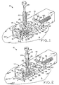
Figure 1 is an oblique view of a first embodiment of the inventive device positioned against the skin of the patient and in a first state, prior to lesion excision, with the forceps retracted; -
Figure 2 shows the device ofFigure 1 in a second, sequential state, prior to lesion excision, with the forceps extended and capturing the lesion to be excised; -
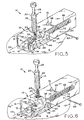
Figure 3 shows the device ofFigure 1 in a third, sequential state, prior to lesion excision, with the forceps shown in a lesion-pulling position and the safety pin removed; -
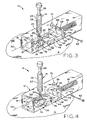
Figure 4 shows the device ofFigure 1 in a fourth, sequential state, during lesion excision, with the staple partially closed through the skin surrounding the lesion; -
Figure 5 shows the device ofFigure 1 in a fifth, , sequential state, during lesion excision, with the staple more fully closed; -
Figure 6 shows the device ofFigure 1 in a sixth, sequential state, after lesion excision, with the staple fully closed, the forceps being withdrawn from the device and removing the lesion from the skin; -
Figure 7 shows the device ofFigure 1 in a seventh, sequential state, after lesion excision, the device housing being removed from the skin, the forceps holding the excised lesion fully removed from the device housing; -
Figure 8 is an enlarged fragmentary sectional view of the exciser ofFigure 1 along line 8-8, showing the staple retention feature of the housing and the position of a lesion to be excised from the skin; -
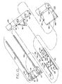
Figure 9 is an oblique view of a second embodiment of the inventive device located on the skin of the patient, assembled and in a first, open position; -
Figure 10 is a view of the component parts of the device ofFigure 9 in a disassembled state; -
Figure 1 is an oblique view of the first applicator block of the device ofFigure 9 , with the male staple half inserted therein; -
Figure 12 is an oblique view of the second applicator block of the device ofFigure 9 , with the female staple half inserted therein; -
Figure 13 is an oblique view of the blade assembly of the device ofFigure 9 ; -
Figure 14 is an oblique view of the blade assembly ofFigure 13 fitted to the second applicator block ofFigure 12 ; -
Figure 15 is a view of the male and female staple halves ofFigures 11 and 12 , respectively, shown interfitted; -
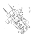
Figure 16 shows the device ofFigure 9 in a first state, prior to lesion excision; -
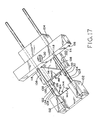
Figure 17 shows the device ofFigure 9 in a second, sequential state, prior to lesion excision and during interfitting of the staple halves; -
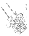
Figure 18 shows the device ofFigure 9 in a third, sequential state, prior to lesion excision but after closure of the staple; -
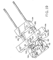
Figure 19 shows the device ofFigure 9 in a forth, sequential state, during lesion excision; -
Figure 20 shows the device ofFigure 9 in a fifth, sequential state, upon lesion excision; -
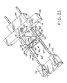
Figure 21 shows the device ofFigure 9 in a sixth, sequential state, after upon completion of the excision and during partial release of the closed staple from the device. - Corresponding reference characters indicate corresponding parts throughout the several views. The exemplifications set out herein illustrate various embodiments of the invention and such exemplifications are not to be construed as limiting the scope of the invention in any manner.
-
Figure 1 shows exciser 10, a first embodiment of the present invention which includesbase assembly 12 andseparable forceps assembly 14. It is envisioned that exciser 10 may be a single use device, all or part of which may be discarded after a lesion has been excised therewith. -
Base assembly 12 includes transparent, elongate plastic housing orframe 16 which, as shown, has the shape of a parallelepiped. It is envisioned, however, thathousing 16 may be of any suitable shape. The lower side ofhousing 16, that side which, in use, lies against skin S of the patient, is provided with rectangularfirst aperture 18 which frames lesion L to be excised. At a location directly oppositefirst aperture 18, the upper side ofhousing 16 is provided with circularsecond aperture 20 into which the end ofcylindrical body 22 offorceps assembly 14 is inserted. -
Forceps assembly 14 further includes forceps ortweezers 24 having a pair of elongate, separable, somewhat flexible arms which are retractable into and extendable from the interior ofcylindrical forceps body 22, andspring 26 which acts to urgetweezers 24 into theinterior body 22.Forceps assembly 14 is also provided withplunger 28 which, when depressed with the thumb, urgestweezers 24 out ofbody 22 against the action ofspring 26, the extended tweezers urged into an open position in which its arms are spread. Release ofplunger 28 allowsspring 26 to forcetweezers 24 upwardly and intobody 22, closing the tweezers. Those of ordinary skill in the art will recognize thatforceps assembly 14 may include a mechanism similar to slender, elongate tools commonly used by mechanics for grasping small parts such as screws and nuts, for example, which have been dropped into hard to reach places. Such grasping tools typically employ spring-biased tweezers which are opened by depression of a plunger, as described above. Alternatively,forceps assembly 14 may include a mechanism (not shown) by which tweezers 24 are similarly extended from a body and opened, or retracted into the body and closed, by turning a screw threaded into the body, the tip of the screw attached to the tweezers inside the body. As a further, unshown alternative,second aperture 20 may be enlarged, orhousing 16 otherwise adequately fashioned to allow the lesion to be manually captured with an ordinary pair of tweezers or forceps. - Disposed inside
housing 16, adjacent tofirst aperture 18, is a skin-closure device which may be made of a surgical stainless steel or a suitable plastic material:Unitary staple 30, in its opened condition, is somewhat V-shaped, having a pair of distant, splayed straight legs, 32 and 34, each having an end integrally connected tocentral portion 36 which extends between one end of the legs. The free end oflegs barbs Staple 30 may be lightly adhered to the inside surface ofhousing 16 to help maintain its position prior to being closed. - The interfacing, or inward sides of
legs pins 42 which extend therefrom and which, when the staple is closed, are alternating relative to the legs from which they extend. When the staple is closed, and pins 42 extend through the skin below the excision site, the pointed free end of eachpin 42 abuts or is at least proximal the inward side of the opposite leg. It is to be understood thatstaple 30, and/or any of the other skin-closure devices or staples described further herein below, are exemplary embodiments which may be adapted for use with the inventive excisers. It is envisioned that other types of skin-closure devices which serve to close or maintain closed the skin at the lesion excision site may also be in accordance with the present invention, and such devices or the use thereof fall within the scope of the present invention. -
Housing 16 is provided with inverted U-shaped clip 43 (Figure 8 ) which is integrally molded or otherwise attached thereto at the edge of rectangularfirst aperture 18nearest blade assembly 44.Clip 43 surrounds three sides of staplecentral portion 36 to prevent its movement longitudinally ofhousing 16 when engaged by the blade assembly, as disclosed further below. Notably, the opening ofclip 43 is located overfirst aperture 18 such that, upon removal ofbase assembly 12 from the skin of the patient after excision of the lesion,closed staple 30 may exit the housing with clearance between itscentral portion 36 and the adjacent edge offirst aperture 18. Note that excisers and skin-closure devices of different sizes may be provided to accommodate the excision various sized lesions and closure of skin at the excision site. - Also disposed within
housing 16 isblade assembly 44 which includessurgical steel blade 46 fixed between wedges or hammers 48 and 50.Hammers blade assembly 44 and are provided withsurfaces longitudinal axis 55 ofhousing 16. As will be described further hereinbelow, during actuation ofexciser 10, hammers 48 and 50 andblade 46 move coincidentally such that surfaces 52 and 54 slidably engagelegs legs blade 46. Notably, the sharp edge ofblade 46 is located adjacent tosurfaces legs axis 55 are squeezed together bysurfaces clip 43 is located well beneathblade 46 so that the clip will not interfere with the blade's movement. -
Blade assembly 44 further includesblock 56 to which hammers 48 and 50 andblade 46 are attached.Block 56 is provided withpost 58 which extends vertically and hole 60 (Figures 3-7 ) which extends laterally.Base assembly 12 is also provided with removableelongate safety pin 62 which, prior to actuation ofexciser 10, extends intohole 60 and throughhole 64 inhousing 16. -
Compression spring 66 is provided insidehousing 16, and has one end fixed relative to the housing; the other end abutsblock 56.Spring 66 thus urgesblade assembly 44 from its cocked position alongaxis 55 towardstaple 30. Withsafety pin 62 installed,blade assembly 44 is retained in its cocked position against the force ofcompression spring 66 and may not be inadvertently actuated or triggered. Withsafety pin 62 installed,blade assembly 44 thus may not be slidably moved withinhousing 16 alongaxis 55.Base assembly 12 also provided withplunger 68 which extends through the lateral wall ofhousing 16 and hashead 70, the depression of which triggersblade assembly 44 oncesafety pin 62 has been removed. -
Plunger 68 is provided with J-shaped latching end or hook 72 which, in the blade assembly cocked position, partially surroundspost 58, the free end ofhook 72 extending laterally in a direction perpendicular toaxis 55 and abutting the post. Depression ofplunger head 70 moves plunger 68 laterally such thatpost 58 is no longer captured withinhook 72 and, withsafety pin 62 removed,spring 66 will then immediately forceblade assembly 44 to move alongaxis 55 toward the lesion andstaple 30. - The operation of
exciser 10 will now be described with sequential reference toFigures 1-7 . Thebody 16 ofbase assembly 12 is placed against skin S of the patient such that lesion L to be excised is framed byaperture 18, andsafety pin 62 is removed. Referring toFigure 2 ,plunger 28 offorceps assembly 14 is depressed againstspring 26 andtweezers 24 are extended into the interior ofhousing 16 and expand. The free ends oftweezers 24, which may be serrated for enhanced gripping ability, acquire or grab the lesion and, with reference toFigure 3 ,plunger 28 is released. Under the influence ofspring 26, tweezers 24 are at least partially retracted intocylindrical body 22 and pull the lesion upwardly throughaperture 18.Parallel lines body 16, andblade 46 lies and moves in aplane containing lines - Because
body 16 is transparent, the doctor or nurse practitioner can establish the desired elevated position of the lesion byfirst sighting lines forceps assembly 14, if and as necessary, such that perimeter P of lesion L, which may be irregularly shaped, is pulled to a position above the superposed lines, as best shown inFigure 8 . So positioned, the lesion will, after actuation of the blade assembly, be placed in proximity toblade 46 which cuts the skin located outside lesion perimeter P. In adjustingforceps assembly 14, itsbody 22 may be moved relative tobase assembly housing 16, or itsplunger 28 may be pulled further upward, drawingtweezers 24 further intobody 22. Alternatively, as mentioned above, the lesion may be captured manually using an ordinary pair of tweezers or forceps and appropriately positioned prior to triggeringblade assembly 44. As a further alternative, the lesion may be captured with a skin hook (not shown) and appropriately positioned prior to triggering the blade. - Once the lesion is in its desired position within
housing 16,blade assembly 44 is triggered by depression ofplunger head 70. In immediate response to the free end ofplunger hook 72 sliding clear ofblock post 58,blade assembly 44 quickly moves alongaxis 55.Blade 46 passes below the free ends oftweezers 24 and through the skin outside of lesion perimeter P, slicing the lesion from the skin whilestaple 30 simultaneously closes the skin at a location below the excision site. During closure ofstaple 30, assurfaces hammers close legs staple legs - Referring to
Figures 5 and 6 , the flat interfacing and parallel surfaces ofhammers central portion 36 ofstaple 30 fits closely therebetween and when barbed ends 38 and 40 of the staple become interlocked, the staple will assume a rectangular shape which is smaller than the periphery of rectangularfirst aperture 18. Afterblade assembly 44 has traveled its entire distance alongaxis 55, the lesion will be fully excised from the skin andstaple 30 is completely closed.Base assembly 12 may then be removed from the patient's skin,closed staple 30 passing throughfirst aperture 18.Forceps assembly 14, still gripping the excised lesion, may then be withdrawn fromhole 20 ofhousing 16. InFigure 7 ,forceps assembly 14 is shown having been completely and separably withdrawn frombase assembly 12 with the excised lesion captured between the ends oftweezers 24. The excised lesion may then be discarded or sent to a laboratory for biopsy or other analysis as appropriate. - It is envisioned that after approximately four days the excision wound will have sufficiently healed that
staple 30 may be removed.Staple 30 may be removed by cutting it, perhaps at itscentral portion 36, and peeling itslegs pins 42 therefrom. - Referring now to
Figures 9-21 , there is shown exciser 100, a second embodiment of the present invention which was prototyped and successfully used in animal experiments. -
Exciser 100 comprisesfirst applicator block 102 andsecond applicator block 104. Disposed between the applicator blocks isblade assembly 106.Guide rods 108 are fixed withinbores 110 provided infirst applicator block 102 and slidably extend throughbores 112 insecond applicator block 104. First and second applicator blocks 102 and 104 may be made of a polymeric material such as nylon, for example. -
Blade assembly 106 comprisesblock portion 114 andblade 116.Block portion 114 is made of a material similar to that of applicator blocks 102,104, andblade 116 is surgical steel or suitable plastic material, likeblade 46 offirst embodiment exciser 10.Blade 116 is attached to blockportion 114 through means offastener 120 or by any other suitable means.Guide rods 108 slidably extend throughbores 118 provided in bladeassembly block portion 114. - The basic components of
exciser 100 and its associated skin-closure device are shown inFigure 10 . Two-part staple 122 comprises interfittingmale half 124 andfemale half 126. Malestaple half 124 comprises a pair ofparallel rod portions 128, and femalestaple half 126 comprises a pair of similarly spacedparallel tube portions 130.Rod portions 128 each include extendingportion 132 and pointed engagingportion 134.Tube portions 130 each include extendingportion 136 and engagingportion 138. As further described hereinbelow, each solid engagingportion 134 of the male staple half slidably and interferingly engages its mating hollow engagingportion 138 of femalestaple half 124 during closure of the staple. When staple halves 124 and 126 are separated or less than fully seated,staple 122 is in its open condition, and when staple halves 124 and 126 are fully engaged,staple 122 is in its closed condition. The interference fit between engagingportions staple 122 remains in its closed condition after excision of the lesion. - Extending between and fixed to
rod portions 128 of malestaple half 124 iselongate leg 140, and extending between and fixed totube portions 130 of femalestaple half 126 iselongate leg 142. When fitted intoexciser 100, or whenstaple 122 is closed,legs tube portions legs pins 144, which correspond topins 42 offirst embodiment exciser 10 shown inFigures 1 through 8 .Pins 144 extend in the longitudinal directions of engagingportions staple 122 is closed, the pins of the male and female staple halves are misaligned such that they alternate along the legs, and the pointed tips of the pins of one staple half are in close proximity to the leg of the opposite staple half. Notably, whenstaple 122 is closed as shown inFigure 15 , engagingportions 134 of malestaple half 124 extend beyond the engagingportion 138 of femalestaple half 126 and into the female staple halfs tubular extendingportions 136. The distance betweenparallel legs staple 122 is closed may be limited by the length of female staplehalf engaging portion 138 relative to itsleg 142, i.e., the ends of engagingportions 136abut leg 140, thereby minimizing the distance between the staple legs. - Referring again to
Figure 9 , it can be seen that prior to excision of lesion L from skin S, extendingportions holes portions 132 of malestaple half 124, and the male staple half is slid intofirst applicator block 102 until the interfacing surfaces of the first applicator block andleg 140 abut. Similarly, extendingportions 136 of femalestaple half 126 are slidably received inholes 148 provided insecond applicator block 104, with the interfacing surfaces of the second applicator block andleg 142 abutting. -
Figures 9 and16 show exciser 100 loaded with astaple 122 and in its open condition, in whichlegs exciser 100 is placed onto skin S of the patient. Perimeter P of lesion L to be excised is framed betweenlegs engaging portions 134 of the malestaple half 124. Is it again noted that excisers and staples of different sizes may be provided to accommodate the excision various sized lesions and closure of the excision site. During operation ofexciser 100,first applicator block 102 is held stationary relative to the patient's skin andsecond applicator block 104 andblade assembly 106 are moved relative tofirst applicator block 102 alongguide rods 108. - Lesion L to be excised with
exciser 100 may be pulled away from skin S through a means of ordinary tweezers or forceps (not shown). Alternatively, the lesion may be captured and pulled away from the skin with a skin hook (not shown). Lesion L is pulled throughexciser 100, between the staple legs and the engaging portions of the male staple half, to an extent which places its perimeter P on the side of the plane defined byblade 116 opposite that on whichstaple 122 is located. This ensures that the entire lesion, and not just a portion thereof, will be excised byblade 116 and the staple will close the skin beneath the excision site by pinching together, betweenproximate legs staple 122 into an elliptical shape, and the dermis of the skin, rather than merely the epidermis is brought into and held in abutting contact by the closed staple to promote faster healing. - Referring to
Figures 16-20 , the sequence of movements ofexciser 100 and its staple halves are shown sequentially. Prior to the cutting of the skin byblade 116, it can be seen (Figures 16-18 ), thatplanar blade 116 overliesflat surface 150 ofsecond applicator block 104 and thus cannot begin cutting engagement with the patient's skin untilblade assembly 106 is moved relative tosecond applicator block 104 alongguide rods 108. -
Figure 17 shows thesecond applicator block 104 andblade assembly 106 having been moved together alongguide rods 108 towardfirst applicator block 102 such that engagingportions staple 122 has begun prior to any cutting byblade 116. -
Figure 18 shows that further movement ofsecond applicator block 104 andblade assembly 106 together alongguide rods 108 towardfirst applicator block 102 has completely closedstaple 122, applicator blocks 102 and 104 being in their closest proximity to each other. Notably, unlikefirst embodiment exciser 10, in which excision of the lesion and closure of the excision site are done substantially simultaneously,exciser 100 completely closesstaple 122 prior to any cutting byblade 116. Lesion L, which had previously been pulled outwardly away from the rest of the patient's skin by ordinary tweezers or forceps, is held in place such that its perimeter P is above the plane defined byflat blade 116 by the staple.Pins 144, which pierce the skin, support the lesion above the plane defined byflat blade 116; but the lesion may still be grasped by the tweezers or forceps for easy handling after excision. - Referring to
Figure 19 , it can be seen that movement ofblade assembly 106 relative tosecond applicator block 104 alongguide rods 108 and towardfirst applicator block 102forces blade 116 over the closed staple and through the patient's skin, preferably outside of the perimeter of the lesion. Here it can be seen that asblade 116 is moved, it is received inrecess 152 formed infirst applicator block 102. - Referring to
Figure 20 ,exciser 100 is shown in a position in which the lesion has been completely severed and perhaps removed from the excision site by the tweezers or forceps. In this position, the interfacing surfaces offirst applicator block 102 and bladeassembly block portion 114 abut, and further movement ofblade assembly 106 alongguide rods 108 away fromsecond applicator block 104 is prevented. - Finally, with reference to
Figure 21 ,blade assembly 106 is reversely slid alongguide rods 108 back to its initial position relative tosecond applicator block 104, andsecond applicator block 104 andblade assembly 106 are held together.First applicator block 102 is moved away fromsecond applicator block 104 andblade assembly 106, withdrawingguide rods 108 therefrom. Extendingportions 132 ofstaple 122 are withdrawn fromholes 146 infirst applicator block 102. The position ofstaple 122 of course remains stationary relative to skinS. Extending portions 136 ofstaple 122 are then withdrawn fromholes 148 insecond applicator block 104 and the exciser completely removed from the patient. The extending portions ofstaple 122 may then be trimmed to reduce the size of the staple. As noted above, it is anticipated thatstaple 122 would remain in place for approximately four days while the excision site heals, after which the staple halves may be separated by pulling them apart, overcoming the interference fit between the engagingportions - While the present invention has been described as having exemplary structures and methods, the present invention can be further modified scope of this disclosure. This application is therefore intended to cover any variations, uses, or adaptations of the invention which fall within the limits of the appended claims.
Claims (10)
- A skin lesion exciser (10,100) comprising:a base assembly(12);a moving blade (46, 242), disposed within the base assembly (12), wherein excision of a skin lesion placed in proximity to said blade (46, 242) is effected by movement of said blade (46, 242) against the skin;an aperture (18) defined by the base assembly (12) and adapted to frame the skin lesion;a moving engagement portion (48, 50), wherein said blade (46) and said engagement portion (48, 50)have coincident movement; anda skin-closure device (30, 122)having an open condition prior to excision of the skin lesion, and a closed condition in which said skin-closure device (30, 122) holds the skin closed after excision of the skin lesion, said skin-closure device (30, 122) being in engagement with said engagement portion (48,50) during movement of said blade (46), said skin-closure device (30, 122) being moved from its said open to its said closed condition in response to movement of said engagement portion (48,50), whereby the excision of the skin lesion and the closure of the skin are substantially simultaneous.
- The skin lesion exciser (10,100) of claim 1, wherein said blade (46, 242) is a single blade.
- The skin lesion exciser (100) of claim 1, wherein said blade is one of two blades (242) which are moved toward each other during excision of the lesion from the skin.
- The skin lesion exciser (10,100) of claim 1, further comprising integral forceps (220) with which the lesion is grasped.
- The skin lesion exciser (10,100) of claim 1, further comprising separable forceps (14) with which the lesion is grasped.
- The skin lesion exciser (10,100) of claim 1, wherein said skin-closure device (30) comprises a pair of legs (32, 34) which are moved toward each other as said skin-closure device (30, 122) is moved from its said open condition to its said closed condition.
- The skin lesion exciser (10) of claim 6, wherein said skin-closure device (30) is unitary.
- The skin lesion exciser (100) of claim 6, wherein said skin-closure device (122) is comprised of two separate pieces (124, 126), each device piece (124, 126) including one of said device legs (140, 142), said device pieces (124, 126) being connected to each other in said device closed condition.
- The skin lesion exciser (100) of claim 8, wherein said device pieces (124, 126) are interference-fitted together in said device closed condition.
- The skin lesion exciser (10,100) of claim 1, wherein said skin-closure device (30, 122) includes skin-piercing portions (42,144) which protrude through the skin in said device closed condition, whereby said skin-closure device (30, 122) is secured to the closed skin.
Applications Claiming Priority (7)
| Application Number | Priority Date | Filing Date | Title |
|---|---|---|---|
| US32625401P | 2001-10-01 | 2001-10-01 | |
| US326254P | 2001-10-01 | ||
| US33227601P | 2001-11-14 | 2001-11-14 | |
| US332276P | 2001-11-14 | ||
| US35752002P | 2002-02-15 | 2002-02-15 | |
| US357520P | 2002-02-15 | ||
| PCT/US2002/031037 WO2003028563A2 (en) | 2001-10-01 | 2002-09-30 | Skin lesion exciser and skin-closure device therefor |
Publications (2)
| Publication Number | Publication Date |
|---|---|
| EP1434529A2 EP1434529A2 (en) | 2004-07-07 |
| EP1434529B1 true EP1434529B1 (en) | 2009-09-23 |
Family
ID=27406448
Family Applications (1)
| Application Number | Title | Priority Date | Filing Date |
|---|---|---|---|
| EP20020763795 Expired - Lifetime EP1434529B1 (en) | 2001-10-01 | 2002-09-30 | Skin lesion exciser and skin-closure device therefor |
Country Status (11)
| Country | Link |
|---|---|
| US (1) | US7806907B2 (en) |
| EP (1) | EP1434529B1 (en) |
| JP (1) | JP4156514B2 (en) |
| AT (1) | ATE443480T1 (en) |
| AU (1) | AU2002327785B2 (en) |
| CA (1) | CA2460949C (en) |
| DE (1) | DE60233810D1 (en) |
| IL (1) | IL160958A0 (en) |
| MX (1) | MXPA04002966A (en) |
| WO (1) | WO2003028563A2 (en) |
| ZA (1) | ZA200402461B (en) |
Families Citing this family (14)
| Publication number | Priority date | Publication date | Assignee | Title |
|---|---|---|---|---|
| WO2003028563A2 (en) | 2001-10-01 | 2003-04-10 | The Cleveland Clinic Foundation | Skin lesion exciser and skin-closure device therefor |
| US7513902B2 (en) * | 2001-10-01 | 2009-04-07 | The Cleveland Clinic Foundation | Skin lesion exciser and skin-closure device therefor |
| US7799042B2 (en) | 2004-05-13 | 2010-09-21 | The Cleveland Clinic Foundation | Skin lesion exciser and skin-closure device therefor |
| RU2008116614A (en) * | 2005-09-26 | 2009-11-10 | Конинклейке Филипс Электроникс Н.В. (Nl) | SUBSTANCE SAMPLING AND / OR SUBSTANCE DELIVERY THROUGH SKIN |
| US20070232954A1 (en) * | 2006-04-04 | 2007-10-04 | Harris Jeffrey P | Automated skin biopsy device |
| CA2835126C (en) * | 2011-05-10 | 2019-06-11 | Minhhia Ngan Le | Methods and apparatus for securing a medical clamp to a patient |
| US8556915B2 (en) * | 2011-05-26 | 2013-10-15 | Derm Instruments & Innovations Llc | Skin removal instrument |
| WO2014210565A2 (en) | 2013-06-28 | 2014-12-31 | Le Duc Hong | Catheter anchoring device and method |
| US9993230B2 (en) | 2014-08-21 | 2018-06-12 | Seton Healthcare Family | Shave biopsy devices and related methods |
| CN105997193B (en) * | 2016-07-27 | 2018-10-09 | 中国人民解放军第三军医大学第二附属医院 | Medical spring forceps |
| WO2018119480A1 (en) * | 2016-12-23 | 2018-06-28 | Cedars-Sinai Medical Center | Devices and methods for performing skin biopsies |
| JP6844842B2 (en) * | 2017-03-08 | 2021-03-17 | 学校法人 芝浦工業大学 | Medical forceps and medical forceps system |
| CN112137686B (en) * | 2020-09-24 | 2021-09-10 | 青岛市城阳区人民医院 | Scab removing device for burn department |
| CN114027939B (en) * | 2021-11-22 | 2023-05-23 | 中国人民解放军空军军医大学 | Wart body cutting device for dermatology |
Family Cites Families (60)
| Publication number | Priority date | Publication date | Assignee | Title |
|---|---|---|---|---|
| US363538A (en) | 1887-05-24 | Suegical | ||
| US2156351A (en) * | 1938-08-08 | 1939-05-02 | Paul Gertrude | Child's feeding bowl |
| US2994321A (en) | 1958-02-26 | 1961-08-01 | Mueller & Company V | Punch |
| US3391690A (en) | 1965-04-05 | 1968-07-09 | Armao Thomas Anthony | Biopsy instrument including tissue heating or cooling means and method of use |
| US3373742A (en) | 1965-09-02 | 1968-03-19 | United Carr Inc | Bandage fastener and assembly |
| US3353531A (en) | 1965-10-22 | 1967-11-21 | Armao Thomas Anthony | Biopsy instrument with specimen lifting means |
| US3323208A (en) | 1965-11-08 | 1967-06-06 | Jr James S Hurley | Simultaneous clamping and cutting means |
| US3520306A (en) | 1967-11-08 | 1970-07-14 | Johnson & Johnson | Wound closure |
| SU314382A1 (en) | 1970-05-04 | 1973-08-28 | Б. А. Смирнов, В. Л. Рынков, Н. Д. Лукичев , Э. И. Аксенова Всесоюзный научно исследовательский институт хирургической аппаратуры , инструментов | |
| US3857140A (en) | 1973-02-28 | 1974-12-31 | Rubricius J | Detachable bandage clasp |
| US4399810A (en) | 1979-11-28 | 1983-08-23 | Samuels Peter B | Skin clip and applier |
| DE3111996A1 (en) * | 1981-03-26 | 1982-10-14 | Lee, George S., 90021 Los Angeles, Calif. | Skin clip and device for applying such a clip |
| US4465071A (en) | 1981-10-26 | 1984-08-14 | Samuels Peter B | Method of applying skin clips |
| DK103483A (en) * | 1982-04-15 | 1983-10-16 | Ethicon Inc | SILICONE COATED SURGICAL PAPER |
| US4467805A (en) * | 1982-08-25 | 1984-08-28 | Mamoru Fukuda | Skin closure stapling device for surgical procedures |
| US4682598A (en) * | 1984-08-23 | 1987-07-28 | Dan Beraha | Vasectomy instrument |
| US4651753A (en) | 1984-10-12 | 1987-03-24 | Jayco Pharmaceuticals | Endoscopic multiple biopsy instrument |
| US5127915A (en) * | 1984-10-29 | 1992-07-07 | Mattson Philip D | Surgical instrument for severing and clamping an umbilical cord |
| US4610251A (en) | 1985-04-19 | 1986-09-09 | Kumar Sarbjeet S | Surgical staple |
| US4671280A (en) * | 1985-05-13 | 1987-06-09 | Ethicon, Inc. | Surgical fastening device and method for manufacture |
| US4754756A (en) | 1986-12-12 | 1988-07-05 | Shelanski Morris V | Dermatome |
| US4815468A (en) | 1987-01-09 | 1989-03-28 | Annand David S | Sutureless closure |
| CA1303934C (en) | 1987-11-03 | 1992-06-23 | David T. Green | Fascia clip |
| US4943295A (en) | 1988-07-13 | 1990-07-24 | Hartlaub Thaddeus J | Surgical cutting tool |
| IN177831B (en) * | 1989-07-13 | 1997-02-22 | Nat Res Dev | |
| DE3941108C1 (en) | 1989-12-13 | 1991-06-27 | Richard Wolf Gmbh, 7134 Knittlingen, De | |
| US5213907A (en) | 1990-10-09 | 1993-05-25 | Diamond Technologies Company | Nickel-cobalt-boron-alloy deposited on a substrate |
| US5104394A (en) * | 1990-11-05 | 1992-04-14 | Knoepfler Dennis J | Automatic stapler for laparoscopic procedure with selective cutter and suction irrigator |
| US5133730A (en) | 1991-05-15 | 1992-07-28 | International Technidyne Corporation | Disposable-retractable finger stick device |
| US5190560A (en) | 1991-06-20 | 1993-03-02 | Woods John B | Instrument for ligation and castration |
| US5176703A (en) | 1991-10-30 | 1993-01-05 | Peterson Meldon L | Sutureless closure for a skin wound or incision |
| CA2088883A1 (en) * | 1992-02-13 | 1993-08-14 | David T. Green | Endoscopic ligating instrument |
| US5209755A (en) * | 1992-06-05 | 1993-05-11 | Stella Abrahan | Dermal exciser |
| US5258012A (en) | 1992-06-30 | 1993-11-02 | Ethicon, Inc. | Surgical fasteners |
| US5358510A (en) | 1993-01-26 | 1994-10-25 | Ethicon, Inc. | Two part surgical fastener |
| JP2630197B2 (en) | 1993-04-28 | 1997-07-16 | 株式会社ニッショー | Blood suction device |
| US5624451A (en) | 1993-10-18 | 1997-04-29 | American Safety Razor | Flexible blade for removing skin lesions |
| US5423857A (en) | 1993-11-02 | 1995-06-13 | Ethicon, Inc. | Three piece surgical staple |
| US5425741A (en) | 1993-12-17 | 1995-06-20 | Autogenics | Tissue cutting die |
| US5425740A (en) | 1994-05-17 | 1995-06-20 | Hutchinson, Jr.; William B. | Endoscopic hernia repair clip and method |
| AU2818895A (en) * | 1994-06-10 | 1996-01-05 | University Of Massachusetts Medical Center | Safety lock needle |
| US5628759A (en) | 1994-09-29 | 1997-05-13 | American Safety Razor Company | Flexible surgical razor |
| US5674234A (en) | 1994-09-29 | 1997-10-07 | American Safety Razor Company | Flexible surgical razor |
| US5555892A (en) | 1994-11-14 | 1996-09-17 | Tipton; Clyde C. | Biopsy shaver |
| US5620452A (en) * | 1994-12-22 | 1997-04-15 | Yoon; Inbae | Surgical clip with ductile tissue penetrating members |
| US6015417A (en) | 1996-01-25 | 2000-01-18 | Reynolds, Jr.; Walker | Surgical fastener |
| US5842999A (en) | 1996-07-31 | 1998-12-01 | C.R. Bard, Inc. | Automated tissue sampling device |
| US6811555B1 (en) | 1996-09-16 | 2004-11-02 | Origin Medsystems, Inc. | Method and apparatus for performing anastomosis with eversion of tissue edges and joining of exposed intima of the everted tissue |
| US5868763A (en) | 1996-09-16 | 1999-02-09 | Guidant Corporation | Means and methods for performing an anastomosis |
| US5931847A (en) | 1997-01-09 | 1999-08-03 | Ethicon Endo-Surgery, Inc. | Surgical cutting instrument with improved cutting edge |
| US5985217A (en) | 1997-07-17 | 1999-11-16 | The Regents Of The University Of California | Microfabricated instrument for tissue biopsy and analysis |
| US6146399A (en) | 1997-10-08 | 2000-11-14 | Lee; Scott S. | Tissue cutting clamp apparatus |
| US6106542A (en) * | 1998-01-23 | 2000-08-22 | Microsurgical Laboratories, Inc. | Surgical forceps |
| WO2000056227A1 (en) | 1999-03-19 | 2000-09-28 | By-Pass, Inc. | Advanced closure device |
| US6126615A (en) | 1998-07-10 | 2000-10-03 | Allen; Michael E | Sutureless guided skin biopsy system |
| US6758824B1 (en) | 2000-11-06 | 2004-07-06 | Suros Surgical Systems, Inc. | Biopsy apparatus |
| US7211101B2 (en) | 2000-12-07 | 2007-05-01 | Abbott Vascular Devices | Methods for manufacturing a clip and clip |
| US6719777B2 (en) | 2000-12-07 | 2004-04-13 | Integrated Vascular Systems, Inc. | Closure device and methods for making and using them |
| US6623510B2 (en) | 2000-12-07 | 2003-09-23 | Integrated Vascular Systems, Inc. | Closure device and methods for making and using them |
| WO2003028563A2 (en) | 2001-10-01 | 2003-04-10 | The Cleveland Clinic Foundation | Skin lesion exciser and skin-closure device therefor |
-
2002
- 2002-09-30 WO PCT/US2002/031037 patent/WO2003028563A2/en active Application Filing
- 2002-09-30 IL IL16095802A patent/IL160958A0/en unknown
- 2002-09-30 MX MXPA04002966A patent/MXPA04002966A/en unknown
- 2002-09-30 CA CA 2460949 patent/CA2460949C/en not_active Expired - Fee Related
- 2002-09-30 JP JP2003531904A patent/JP4156514B2/en not_active Expired - Fee Related
- 2002-09-30 AT AT02763795T patent/ATE443480T1/en not_active IP Right Cessation
- 2002-09-30 US US10/261,155 patent/US7806907B2/en not_active Expired - Fee Related
- 2002-09-30 AU AU2002327785A patent/AU2002327785B2/en not_active Ceased
- 2002-09-30 EP EP20020763795 patent/EP1434529B1/en not_active Expired - Lifetime
- 2002-09-30 DE DE60233810T patent/DE60233810D1/en not_active Expired - Lifetime
-
2004
- 2004-03-29 ZA ZA2004/02461A patent/ZA200402461B/en unknown
Also Published As
| Publication number | Publication date |
|---|---|
| DE60233810D1 (en) | 2009-11-05 |
| US7806907B2 (en) | 2010-10-05 |
| CA2460949C (en) | 2008-12-16 |
| IL160958A0 (en) | 2004-08-31 |
| WO2003028563A3 (en) | 2003-08-07 |
| AU2002327785B2 (en) | 2006-06-01 |
| ATE443480T1 (en) | 2009-10-15 |
| WO2003028563A2 (en) | 2003-04-10 |
| US20030078596A1 (en) | 2003-04-24 |
| JP4156514B2 (en) | 2008-09-24 |
| EP1434529A2 (en) | 2004-07-07 |
| ZA200402461B (en) | 2005-06-29 |
| MXPA04002966A (en) | 2005-06-20 |
| JP2005504580A (en) | 2005-02-17 |
| CA2460949A1 (en) | 2003-04-10 |
Similar Documents
| Publication | Publication Date | Title |
|---|---|---|
| EP1744680B1 (en) | Skin lesion exciser and skin-closure device therefor | |
| US7799042B2 (en) | Skin lesion exciser and skin-closure device therefor | |
| EP1434529B1 (en) | Skin lesion exciser and skin-closure device therefor | |
| US5015252A (en) | Surgical forceps with suture cutters | |
| USRE38776E1 (en) | Surgical biopsy instrument | |
| US8540646B2 (en) | Biopsy and sutureless device | |
| US8936557B2 (en) | Punch biopsy device | |
| CA2650013A1 (en) | Biopsy punch | |
| AU2002327785A1 (en) | Skin lesion exciser and skin-closure device therefor | |
| JP4628637B2 (en) | Biopsy equipment | |
| US20160151085A1 (en) | Biopsy Tool | |
| JP6745359B2 (en) | Skin biopsy sample collection device | |
| US20150057572A1 (en) | Biopsy and sutureless device | |
| JP5775866B2 (en) | Medical instruments | |
| US11559326B2 (en) | Disposable circumcision apparatus and method of use of this apparatus | |
| US20170055960A1 (en) | Blade Holder | |
| TR2021015546A2 (en) | SELF-BLADE PUNCH TYPE TISSUE SECTION APPARATUS |
Legal Events
| Date | Code | Title | Description |
|---|---|---|---|
| PUAI | Public reference made under article 153(3) epc to a published international application that has entered the european phase |
Free format text: ORIGINAL CODE: 0009012 |
|
| 17P | Request for examination filed |
Effective date: 20040323 |
|
| AK | Designated contracting states |
Kind code of ref document: A2 Designated state(s): AT BE BG CH CY CZ DE DK EE ES FI FR GB GR IE IT LI LU MC NL PT SE SK TR |
|
| AX | Request for extension of the european patent |
Extension state: AL LT LV MK RO SI |
|
| 17Q | First examination report despatched |
Effective date: 20080611 |
|
| GRAP | Despatch of communication of intention to grant a patent |
Free format text: ORIGINAL CODE: EPIDOSNIGR1 |
|
| GRAC | Information related to communication of intention to grant a patent modified |
Free format text: ORIGINAL CODE: EPIDOSCIGR1 |
|
| GRAS | Grant fee paid |
Free format text: ORIGINAL CODE: EPIDOSNIGR3 |
|
| GRAA | (expected) grant |
Free format text: ORIGINAL CODE: 0009210 |
|
| AK | Designated contracting states |
Kind code of ref document: B1 Designated state(s): AT BE BG CH CY CZ DE DK EE ES FI FR GB GR IE IT LI LU MC NL PT SE SK TR |
|
| REG | Reference to a national code |
Ref country code: GB Ref legal event code: FG4D |
|
| REG | Reference to a national code |
Ref country code: CH Ref legal event code: EP |
|
| REG | Reference to a national code |
Ref country code: IE Ref legal event code: FG4D |
|
| REF | Corresponds to: |
Ref document number: 60233810 Country of ref document: DE Date of ref document: 20091105 Kind code of ref document: P |
|
| PG25 | Lapsed in a contracting state [announced via postgrant information from national office to epo] |
Ref country code: FI Free format text: LAPSE BECAUSE OF FAILURE TO SUBMIT A TRANSLATION OF THE DESCRIPTION OR TO PAY THE FEE WITHIN THE PRESCRIBED TIME-LIMIT Effective date: 20090923 Ref country code: SE Free format text: LAPSE BECAUSE OF FAILURE TO SUBMIT A TRANSLATION OF THE DESCRIPTION OR TO PAY THE FEE WITHIN THE PRESCRIBED TIME-LIMIT Effective date: 20090923 |
|
| NLV1 | Nl: lapsed or annulled due to failure to fulfill the requirements of art. 29p and 29m of the patents act | ||
| PG25 | Lapsed in a contracting state [announced via postgrant information from national office to epo] |
Ref country code: CY Free format text: LAPSE BECAUSE OF FAILURE TO SUBMIT A TRANSLATION OF THE DESCRIPTION OR TO PAY THE FEE WITHIN THE PRESCRIBED TIME-LIMIT Effective date: 20090923 |
|
| PG25 | Lapsed in a contracting state [announced via postgrant information from national office to epo] |
Ref country code: ES Free format text: LAPSE BECAUSE OF FAILURE TO SUBMIT A TRANSLATION OF THE DESCRIPTION OR TO PAY THE FEE WITHIN THE PRESCRIBED TIME-LIMIT Effective date: 20100103 Ref country code: CZ Free format text: LAPSE BECAUSE OF FAILURE TO SUBMIT A TRANSLATION OF THE DESCRIPTION OR TO PAY THE FEE WITHIN THE PRESCRIBED TIME-LIMIT Effective date: 20090923 Ref country code: PT Free format text: LAPSE BECAUSE OF FAILURE TO SUBMIT A TRANSLATION OF THE DESCRIPTION OR TO PAY THE FEE WITHIN THE PRESCRIBED TIME-LIMIT Effective date: 20100125 Ref country code: EE Free format text: LAPSE BECAUSE OF FAILURE TO SUBMIT A TRANSLATION OF THE DESCRIPTION OR TO PAY THE FEE WITHIN THE PRESCRIBED TIME-LIMIT Effective date: 20090923 Ref country code: MC Free format text: LAPSE BECAUSE OF NON-PAYMENT OF DUE FEES Effective date: 20090930 |
|
| REG | Reference to a national code |
Ref country code: CH Ref legal event code: PL |
|
| PG25 | Lapsed in a contracting state [announced via postgrant information from national office to epo] |
Ref country code: SK Free format text: LAPSE BECAUSE OF FAILURE TO SUBMIT A TRANSLATION OF THE DESCRIPTION OR TO PAY THE FEE WITHIN THE PRESCRIBED TIME-LIMIT Effective date: 20090923 |
|
| PG25 | Lapsed in a contracting state [announced via postgrant information from national office to epo] |
Ref country code: AT Free format text: LAPSE BECAUSE OF FAILURE TO SUBMIT A TRANSLATION OF THE DESCRIPTION OR TO PAY THE FEE WITHIN THE PRESCRIBED TIME-LIMIT Effective date: 20090923 Ref country code: BE Free format text: LAPSE BECAUSE OF FAILURE TO SUBMIT A TRANSLATION OF THE DESCRIPTION OR TO PAY THE FEE WITHIN THE PRESCRIBED TIME-LIMIT Effective date: 20090923 |
|
| PG25 | Lapsed in a contracting state [announced via postgrant information from national office to epo] |
Ref country code: NL Free format text: LAPSE BECAUSE OF FAILURE TO SUBMIT A TRANSLATION OF THE DESCRIPTION OR TO PAY THE FEE WITHIN THE PRESCRIBED TIME-LIMIT Effective date: 20090923 Ref country code: IE Free format text: LAPSE BECAUSE OF NON-PAYMENT OF DUE FEES Effective date: 20090930 Ref country code: DK Free format text: LAPSE BECAUSE OF FAILURE TO SUBMIT A TRANSLATION OF THE DESCRIPTION OR TO PAY THE FEE WITHIN THE PRESCRIBED TIME-LIMIT Effective date: 20090923 |
|
| PLBE | No opposition filed within time limit |
Free format text: ORIGINAL CODE: 0009261 |
|
| STAA | Information on the status of an ep patent application or granted ep patent |
Free format text: STATUS: NO OPPOSITION FILED WITHIN TIME LIMIT |
|
| 26N | No opposition filed |
Effective date: 20100624 |
|
| PG25 | Lapsed in a contracting state [announced via postgrant information from national office to epo] |
Ref country code: GR Free format text: LAPSE BECAUSE OF FAILURE TO SUBMIT A TRANSLATION OF THE DESCRIPTION OR TO PAY THE FEE WITHIN THE PRESCRIBED TIME-LIMIT Effective date: 20091224 Ref country code: LI Free format text: LAPSE BECAUSE OF NON-PAYMENT OF DUE FEES Effective date: 20090930 Ref country code: CH Free format text: LAPSE BECAUSE OF NON-PAYMENT OF DUE FEES Effective date: 20090930 |
|
| PGFP | Annual fee paid to national office [announced via postgrant information from national office to epo] |
Ref country code: DE Payment date: 20100930 Year of fee payment: 9 |
|
| PG25 | Lapsed in a contracting state [announced via postgrant information from national office to epo] |
Ref country code: BG Free format text: LAPSE BECAUSE OF FAILURE TO SUBMIT A TRANSLATION OF THE DESCRIPTION OR TO PAY THE FEE WITHIN THE PRESCRIBED TIME-LIMIT Effective date: 20090930 |
|
| PG25 | Lapsed in a contracting state [announced via postgrant information from national office to epo] |
Ref country code: LU Free format text: LAPSE BECAUSE OF NON-PAYMENT OF DUE FEES Effective date: 20090930 |
|
| PG25 | Lapsed in a contracting state [announced via postgrant information from national office to epo] |
Ref country code: TR Free format text: LAPSE BECAUSE OF FAILURE TO SUBMIT A TRANSLATION OF THE DESCRIPTION OR TO PAY THE FEE WITHIN THE PRESCRIBED TIME-LIMIT Effective date: 20090923 |
|
| PGFP | Annual fee paid to national office [announced via postgrant information from national office to epo] |
Ref country code: GB Payment date: 20110826 Year of fee payment: 10 Ref country code: FR Payment date: 20110901 Year of fee payment: 10 |
|
| PGFP | Annual fee paid to national office [announced via postgrant information from national office to epo] |
Ref country code: IT Payment date: 20110915 Year of fee payment: 10 |
|
| GBPC | Gb: european patent ceased through non-payment of renewal fee |
Effective date: 20120930 |
|
| REG | Reference to a national code |
Ref country code: FR Ref legal event code: ST Effective date: 20130531 |
|
| PG25 | Lapsed in a contracting state [announced via postgrant information from national office to epo] |
Ref country code: GB Free format text: LAPSE BECAUSE OF NON-PAYMENT OF DUE FEES Effective date: 20120930 Ref country code: DE Free format text: LAPSE BECAUSE OF NON-PAYMENT OF DUE FEES Effective date: 20130403 |
|
| PG25 | Lapsed in a contracting state [announced via postgrant information from national office to epo] |
Ref country code: FR Free format text: LAPSE BECAUSE OF NON-PAYMENT OF DUE FEES Effective date: 20121001 Ref country code: IT Free format text: LAPSE BECAUSE OF NON-PAYMENT OF DUE FEES Effective date: 20120930 |
|
| REG | Reference to a national code |
Ref country code: DE Ref legal event code: R119 Ref document number: 60233810 Country of ref document: DE Effective date: 20130403 |