EP1437151A1 - Automatically retractable safety syringe - Google Patents
Automatically retractable safety syringe Download PDFInfo
- Publication number
- EP1437151A1 EP1437151A1 EP20030000746 EP03000746A EP1437151A1 EP 1437151 A1 EP1437151 A1 EP 1437151A1 EP 20030000746 EP20030000746 EP 20030000746 EP 03000746 A EP03000746 A EP 03000746A EP 1437151 A1 EP1437151 A1 EP 1437151A1
- Authority
- EP
- European Patent Office
- Prior art keywords
- retracting
- inwardly
- plunger
- needle
- disposed
- Prior art date
- Legal status (The legal status is an assumption and is not a legal conclusion. Google has not performed a legal analysis and makes no representation as to the accuracy of the status listed.)
- Granted
Links
Images


Classifications
-
- A—HUMAN NECESSITIES
- A61—MEDICAL OR VETERINARY SCIENCE; HYGIENE
- A61M—DEVICES FOR INTRODUCING MEDIA INTO, OR ONTO, THE BODY; DEVICES FOR TRANSDUCING BODY MEDIA OR FOR TAKING MEDIA FROM THE BODY; DEVICES FOR PRODUCING OR ENDING SLEEP OR STUPOR
- A61M5/00—Devices for bringing media into the body in a subcutaneous, intra-vascular or intramuscular way; Accessories therefor, e.g. filling or cleaning devices, arm-rests
- A61M5/178—Syringes
- A61M5/31—Details
- A61M5/32—Needles; Details of needles pertaining to their connection with syringe or hub; Accessories for bringing the needle into, or holding the needle on, the body; Devices for protection of needles
- A61M5/3205—Apparatus for removing or disposing of used needles or syringes, e.g. containers; Means for protection against accidental injuries from used needles
- A61M5/321—Means for protection against accidental injuries by used needles
- A61M5/322—Retractable needles, i.e. disconnected from and withdrawn into the syringe barrel by the piston
- A61M5/3234—Fully automatic needle retraction, i.e. in which triggering of the needle does not require a deliberate action by the user
-
- A—HUMAN NECESSITIES
- A61—MEDICAL OR VETERINARY SCIENCE; HYGIENE
- A61M—DEVICES FOR INTRODUCING MEDIA INTO, OR ONTO, THE BODY; DEVICES FOR TRANSDUCING BODY MEDIA OR FOR TAKING MEDIA FROM THE BODY; DEVICES FOR PRODUCING OR ENDING SLEEP OR STUPOR
- A61M5/00—Devices for bringing media into the body in a subcutaneous, intra-vascular or intramuscular way; Accessories therefor, e.g. filling or cleaning devices, arm-rests
- A61M5/178—Syringes
- A61M5/31—Details
- A61M5/32—Needles; Details of needles pertaining to their connection with syringe or hub; Accessories for bringing the needle into, or holding the needle on, the body; Devices for protection of needles
- A61M5/34—Constructions for connecting the needle, e.g. to syringe nozzle or needle hub
- A61M5/347—Constructions for connecting the needle, e.g. to syringe nozzle or needle hub rotatable, e.g. bayonet or screw
-
- A—HUMAN NECESSITIES
- A61—MEDICAL OR VETERINARY SCIENCE; HYGIENE
- A61M—DEVICES FOR INTRODUCING MEDIA INTO, OR ONTO, THE BODY; DEVICES FOR TRANSDUCING BODY MEDIA OR FOR TAKING MEDIA FROM THE BODY; DEVICES FOR PRODUCING OR ENDING SLEEP OR STUPOR
- A61M5/00—Devices for bringing media into the body in a subcutaneous, intra-vascular or intramuscular way; Accessories therefor, e.g. filling or cleaning devices, arm-rests
- A61M5/50—Devices for bringing media into the body in a subcutaneous, intra-vascular or intramuscular way; Accessories therefor, e.g. filling or cleaning devices, arm-rests having means for preventing re-use, or for indicating if defective, used, tampered with or unsterile
- A61M5/5013—Means for blocking the piston or the fluid passageway to prevent illegal refilling of a syringe
- A61M5/502—Means for blocking the piston or the fluid passageway to prevent illegal refilling of a syringe for blocking the piston
-
- A—HUMAN NECESSITIES
- A61—MEDICAL OR VETERINARY SCIENCE; HYGIENE
- A61M—DEVICES FOR INTRODUCING MEDIA INTO, OR ONTO, THE BODY; DEVICES FOR TRANSDUCING BODY MEDIA OR FOR TAKING MEDIA FROM THE BODY; DEVICES FOR PRODUCING OR ENDING SLEEP OR STUPOR
- A61M5/00—Devices for bringing media into the body in a subcutaneous, intra-vascular or intramuscular way; Accessories therefor, e.g. filling or cleaning devices, arm-rests
- A61M5/50—Devices for bringing media into the body in a subcutaneous, intra-vascular or intramuscular way; Accessories therefor, e.g. filling or cleaning devices, arm-rests having means for preventing re-use, or for indicating if defective, used, tampered with or unsterile
- A61M5/5066—Means for preventing re-use by disconnection of piston and piston-rod
Definitions
- the present invention relates to an automatically retractable safety syringe, more particularly to a syringe designed to be operated by single hand and to have an automatically retractable needle assembly not allowing for reuse.
- the invention intends to avoid the above-mentioned needle stick injuries and shortcomings of the prior art safety syringe.
- the primary objective of the present invention is to provide a syringe designed to be operated by single hand, to have an automatically retractable needle assembly not allowing for reuse;
- the said automatically retractable safety syringe comprises a needle assembly with a cannula, a needle hub and a rubber O-ring thereof, a needle cap, a retracting spring, a breakable plunger, a plunger rubber gasket and a medicine barrel; in accordance with the structure of the said automatically retractable safety syringe of the present invention, since the breakable plunger is assembled inside the medicine barrel, after being pushed all the way to the end, it is forced to break automatically into two parts for reducing it's length so as to provide enough space for the retracting spring to drive the needle assembly moving along the sliding passages to accomplish the automatically retracting action.
- a needle assembly thereof has a cannula (80) and a needle hub (20) with one end thereof used for receiving the cannula (80) to fitly penetrate through its center; the circumference at the other end is disposed with an annular rubber gasket groove (25) and the convex torus thereof is disposed as a check plate (26) toward one end of an retracting spring (40); a plurality of concave positioning slots (22) are disposed in a proper area at two ends of the needle hub (20) to connect a plurality of proceeding slopes (24) tapered upwardly, a plurality of rotating slide passages (23) concaved inwardly and slanted for rotation as well as to connect a plurality of communicating slide passages (21) concaved inwardly to form an U-shaped slide passage for the needle assembly to make retracting action; a needle hub rubber gasket (30) is used for making a tight seal; an annular retracting spring (40) compresses and expands
- the retaining hook (71) of the medicine barrel (70) of the present invention retains into the positioning slot (22) of the needle hub (20) to prevent the needle assembly from retracting inwardly due to the tension of the spring (40), as shown in FIG. 4A; one end of the long inwardly retracting rod (62) connects to one end of the hollow receiving rod (66) to form the breakable area (63) in an annular or annular block shape, as shown in FIG. 4B; the annular convex ring (73) controls and positions the bottom check ring (64) and the fastening annular groove (65), as shown in FIG. 4C; referring to FIGS.
- the retracting spring (40) has a compressed space; the needle hub (20) is positioned and the convex ring (73) is clipped at the bottom check ring (64); the breakable inwardly retracting plunger (60) is forced inwardly; the retaining hook (71) moves along the proceeding slope (24) to reach the rotating slide passage (23); the retracting spring (40) reaches the limit; the breakable inwardly retracting plunger (60) breaks into two parts; the fastening annular groove (65) fitly clips to the convex ring (73); as shown in FIGS.
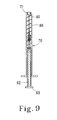
- FIG. 9 indicates the completely destructive state of the plunger (60) of the present invention.
- the retracting spring (40) is first placed through the convex ring (73) of the inner barrel (72), then one end of the needle assembly penetrates through the retracting spring (40); the check plate (26) on the other end stops one end of the retracting spring (40); the positioning slot (22) of the needle hub (20) is positioned and clipped to the retaining hook (71); the area of the retracting spring (40) is in a halfway compressed state; then the breakable inwardly retracting plunger (60) and the plunger rubber gasket (50) retain with a retaining hole (51) via the rubber clip head (61); finally, two sets are assembled and the needle cap (10) is covered onto the retaining hook (71) to finish the assembly.
- the present invention In accordance with the structure of the said automatically retractable safety syringe of the present invention, after the breakable inwardly retracting plunger assembled inside the medicine barrel is pushed all the way to the end, it is forced to break automatically into two parts for reducing it's length so as to provide enough space for the retracting spring to drive the needle assembly moving along the sliding passages for accomplishing the action of automatic retraction; therefore the present invention has less parts and thereby requires lower manufacturing cost; furthermore, the application is simple and safe; the present invention can be manufactured as an automatically retractable safety syringe in a smaller volume.
Abstract
Description
- The present invention relates to an automatically retractable safety syringe, more particularly to a syringe designed to be operated by single hand and to have an automatically retractable needle assembly not allowing for reuse.
- Nowadays, since syringes have been widely used to inject medicine all around the world, needle sticking related injuries occur quite often; the sequelae caused by this kind of accident should not be overlooked because more than twenty kinds of diseases are infected through blood transmission, for example, HIV-1 (AIDS), Hepatitis B and C; it requires a considerable society cost for handling the follow-ups after injury accidents. The prior art safety syringe is usually operated manually by both hands; although the manufacturing cost thereof is low, its application is inconvenient and not safe enough either.
- The invention intends to avoid the above-mentioned needle stick injuries and shortcomings of the prior art safety syringe.
- This technical problem is solved by a syringe according to
claim 1. Further embodiments of the invention are set forth in the claims. - The primary objective of the present invention is to provide a syringe designed to be operated by single hand, to have an automatically retractable needle assembly not allowing for reuse; the said automatically retractable safety syringe comprises a needle assembly with a cannula, a needle hub and a rubber O-ring thereof, a needle cap, a retracting spring, a breakable plunger, a plunger rubber gasket and a medicine barrel; in accordance with the structure of the said automatically retractable safety syringe of the present invention, since the breakable plunger is assembled inside the medicine barrel, after being pushed all the way to the end, it is forced to break automatically into two parts for reducing it's length so as to provide enough space for the retracting spring to drive the needle assembly moving along the sliding passages to accomplish the automatically retracting action.
- To enable a further understanding of the structural features and the technical contents of the present invention, the brief description of the drawings below is followed by the detailed description of the preferred embodiment. In the drawings:
- Figure 1
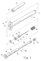
- is an exploded drawing of the present invention.
- Figure 2
- is an enlarged drawing of a needle head of the present invention.
- Figure 3
- is a lateral view and exploded drawing of the present invention.
- Figure 4
- is a lateral view and cross-sectional drawing of the present invention.
- Figure 4A
- is a partially enlarged drawing of the present invention.
- Figure 4B
- is another partially enlarged drawing of the present invention.
- Figure 4C
- is also another partially enlarged drawing of the present invention.
- Figure 5
- is a drawing of the application of the present invention.
- Figure 6
- is another drawing of the application of the present invention.
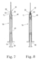
- Figure 7
- is a drawing of the retracting action of the needle assembly of the present invention.
- Figure 8
- is another drawing of the retracting action of the needle assembly of the present invention.
- Figure 9
- is a drawing of the present invention in a destructive state.
- As indicated in FIGS. 1, the exploded drawings of the present invention, a needle assembly thereof has a cannula (80) and a needle hub (20) with one end thereof used for receiving the cannula (80) to fitly penetrate through its center; the circumference at the other end is disposed with an annular rubber gasket groove (25) and the convex torus thereof is disposed as a check plate (26) toward one end of an retracting spring (40); a plurality of concave positioning slots (22) are disposed in a proper area at two ends of the needle hub (20) to connect a plurality of proceeding slopes (24) tapered upwardly, a plurality of rotating slide passages (23) concaved inwardly and slanted for rotation as well as to connect a plurality of communicating slide passages (21) concaved inwardly to form an U-shaped slide passage for the needle assembly to make retracting action; a needle hub rubber gasket (30) is used for making a tight seal; an annular retracting spring (40) compresses and expands to retract the needle assembly; a plunger rubber gasket (50) is also used for making a tight seal; a breakable inwardly retracting plunger (60) is disposed with a long inwardly retracting rod (62) with one end disposed with a rubber clip head (61) to clip the plunger rubber gasket (50) and the other end thereof connected to one end of a hollow receiving rod (66) to form a breakable area (63) in an annular or annular block shape; the other end of the hollow receiving rod (66) is disposed with a push grip (67); an annular bottom check ring (64) is disposed in a proper area at the said two ends for controlling the bottom position of the syringe; an annular fastening annular groove (65) controls and fastens the breakable inwardly retracting plunger (60) to break into two parts and rotate with the needle assembly for completing inwardly retraction; the center of the hollow receiving rod (66) has a space for receiving the inwardly retracting rod (62); one end of a medicine barrel (70) is disposed with a plurality of slightly resilient retaining hook (71) pointing to the center for cooperating with the U-shape of the needle hub; the other end is disposed with a handle lug (74); the aperture of one end of a communicating inner barrel (72) is smaller than that of the inner barrel (72) to form a check ring for stopping the other end of the retracting spring (40); the other end of the said inner barrel (72) is disposed with an annular convex ring (73) for controlling and positioning the bottom check ring (64) and the fastening annular groove (65); the said inner barrel (72) has the space for receiving the needle assembly, the retracting spring (40), the breakable inwardly retracting plunger (60) and the plunger rubber gasket (50) thereof; a needle cap (10) covers to guard the needle assembly and fitly clips unto the retaining hook (71) of the medicine barrel (70); when the needle cap (10) is not separated from the retaining hook (71) of the medicine barrel (70), the retaining hook (71) does not eject for the needle assembly to retract.
- As indicated in FIGS. 2 to 4C, the retaining hook (71) of the medicine barrel (70) of the present invention retains into the positioning slot (22) of the needle hub (20) to prevent the needle assembly from retracting inwardly due to the tension of the spring (40), as shown in FIG. 4A; one end of the long inwardly retracting rod (62) connects to one end of the hollow receiving rod (66) to form the breakable area (63) in an annular or annular block shape, as shown in FIG. 4B; the annular convex ring (73) controls and positions the bottom check ring (64) and the fastening annular groove (65), as shown in FIG. 4C; referring to FIGS. 5 and 6, the retracting spring (40) has a compressed space; the needle hub (20) is positioned and the convex ring (73) is clipped at the bottom check ring (64); the breakable inwardly retracting plunger (60) is forced inwardly; the retaining hook (71) moves along the proceeding slope (24) to reach the rotating slide passage (23); the retracting spring (40) reaches the limit; the breakable inwardly retracting plunger (60) breaks into two parts; the fastening annular groove (65) fitly clips to the convex ring (73); as shown in FIGS. 7 and 8, after the breakable inwardly retracting plunger (60) breaks into two parts, the retracting spring (40) starts to expand to drive the needle hub (20) to rotate and detach completely from the retaining hook (71) along the communicating slide passage (21) till the needle assembly retracts all the way into the inner barrel (72); FIG. 9 indicates the completely destructive state of the plunger (60) of the present invention.
- To assemble the present invention of an automatically retractable safety syringe, the retracting spring (40) is first placed through the convex ring (73) of the inner barrel (72), then one end of the needle assembly penetrates through the retracting spring (40); the check plate (26) on the other end stops one end of the retracting spring (40); the positioning slot (22) of the needle hub (20) is positioned and clipped to the retaining hook (71); the area of the retracting spring (40) is in a halfway compressed state; then the breakable inwardly retracting plunger (60) and the plunger rubber gasket (50) retain with a retaining hole (51) via the rubber clip head (61); finally, two sets are assembled and the needle cap (10) is covered onto the retaining hook (71) to finish the assembly.
- In accordance with the structure of the said automatically retractable safety syringe of the present invention, after the breakable inwardly retracting plunger assembled inside the medicine barrel is pushed all the way to the end, it is forced to break automatically into two parts for reducing it's length so as to provide enough space for the retracting spring to drive the needle assembly moving along the sliding passages for accomplishing the action of automatic retraction; therefore the present invention has less parts and thereby requires lower manufacturing cost; furthermore, the application is simple and safe; the present invention can be manufactured as an automatically retractable safety syringe in a smaller volume.
- It is of course to be understood that the embodiment described herein is merely illustrative of the principles of the invention and that a wide variety of modifications thereto may be effected by persons skilled in the art without departing from the scope of the invention as set forth in the claims.
Claims (4)
- An automatically retractable safety syringe to be adopted for injecting medicine comprises: a needle cannula (80) as well as a rotary and movable needle hub (20); a retracting spring (40) expands to receive a needle assembly in the interior space for storing kinetic energy; a breakable inwardly retracting plunger (60) is capable of breaking into two parts; a plunger rubber gasket (50) is used for making a tight seal; a needle hub rubber gasket (30) is also used for making a tight seal; a needle cap (10) is used for covering and guarding the needle assembly as well as clipping onto a retaining hook of a medicine barrel (70); when the needle cap (10) is not separated from the retaining hook (71) of the medicine barrel, the retaining hook is not able to eject and the needle assembly cannot retract either; an internal body (72) of the medicine barrel (70) has the space for action of the needle assembly, the retracting spring (40), the breakable inwardly retracting plunger (60) and the plunger rubber gasket; characterized in that when the retracting spring area is over the halfway retracting state, the breakable inwardly retracting plunger (60) drives the needle assembly and presses the retracting spring (40) to a proper area; after the breakable inwardly retracting plunger (60) breaks into two parts, the retracting spring (40) starts to expand to drive the needle assembly to rotate along the preset sliding passage for accomplishing the automatically retracting action.
- An automatically retracting safety syringe according to claim 1, characterized in that one end of the needle hub (20) receives the needle cannula (80) fitly penetrating the center thereof for flowing the medicine; the circumference of the other end is disposed with an annular rubber gasket groove (25); the said convex torus is disposed as a check plate (26) at one end of an retracting spring (40); a plurality of concave positioning slots (22) are disposed in a proper area at two ends of the needle hub (20) to connect a plurality of proceeding slopes (24) tapered upwards, a plurality of rotating slide passages (23) concaved inwardly and slanted for rotation as well as to connect a plurality of communicating slide passages (21) concaved inwardly to form at least more than two U-shaped slide passages for the needle assembly to make retracting action;
- An automatically retracting safety syringe according to claim 1 or 2, characterized in that a breakable inwardly retracting plunger (60) is disposed with a long inwardly retracting rod (62) with one end thereof disposed with a rubber clip head (61) to clip with the plunger rubber gasket (50) and the other end thereof connected to one end of a hollow receiving rod (66) to form a breakable cutting edge area in an annular or annular block shape; the other end of the hollow receiving rod (66) is disposed with a push grip (67); an annular bottom check ring (64) is disposed in a proper area at the said two ends for controlling the bottom position of the syringe; an annular fastening annular groove (65) controls and fastens the breakable inwardly retracting plunger (60) to break into two parts and rotate with the needle assembly for completing inwardly retraction; the center of the circumference of the hollow receiving rod (66) has a space for receiving the inwardly retracting rod (62).
- An automatically retracting safety syringe according to claim 1, 2 or 3, characterized in that one end of the cylindrical medicine barrel (70) is disposed with a plurality of slightly resilient retaining hooks (71) pointing to the center of the circumference for cooperating with the U-shape of the needle hub (20); the other end is disposed with a handle lug (74); the aperture of one end of a communicating inner barrel (72) is smaller than that of the inner barrel (72) to form a check ring for stopping the other end of the retracting spring (40); the other end of the said inner barrel (72) is disposed with an annular convex ring (73) for controlling and positioning the bottom check ring (64) and the fastening annular groove (65); the said inner barrel (72) has the space for receiving the needle assembly, the retracting spring (40), the breakable inwardly retracting plunger (60) and the plunger rubber gasket (50) thereof.
Priority Applications (8)
| Application Number | Priority Date | Filing Date | Title |
|---|---|---|---|
| DE60306090T DE60306090T2 (en) | 2003-01-13 | 2003-01-13 | Safety syringe with automatic retractable needle |
| AT03000746T ATE329642T1 (en) | 2003-01-13 | 2003-01-13 | SAFETY SYRINGE WITH AUTOMATIC EXTRACTABLE NEEDLE |
| PT03000746T PT1437151E (en) | 2003-01-13 | 2003-01-13 | AUTOMATICALLY RETRACTABLE SAFETY SYRINGE |
| EP03000746A EP1437151B8 (en) | 2003-01-13 | 2003-01-13 | Automatically retractable safety syringe |
| DK03000746T DK1437151T3 (en) | 2003-01-13 | 2003-01-13 | Safety sprayer with automatic retraction |
| ES03000746T ES2266647T3 (en) | 2003-01-13 | 2003-01-13 | SECURITY SYRINGE WITH AUTOMATIC REMOVAL. |
| SI200330418T SI1437151T1 (en) | 2003-01-13 | 2003-01-13 | Automatically retractable safety syringe |
| CY20061101303T CY1106440T1 (en) | 2003-01-13 | 2006-09-13 | AUTOMATICALLY RETRACTABLE SAFETY SYRINGE |
Applications Claiming Priority (1)
| Application Number | Priority Date | Filing Date | Title |
|---|---|---|---|
| EP03000746A EP1437151B8 (en) | 2003-01-13 | 2003-01-13 | Automatically retractable safety syringe |
Publications (3)
| Publication Number | Publication Date |
|---|---|
| EP1437151A1 true EP1437151A1 (en) | 2004-07-14 |
| EP1437151B1 EP1437151B1 (en) | 2006-06-14 |
| EP1437151B8 EP1437151B8 (en) | 2006-10-25 |
Family
ID=32479920
Family Applications (1)
| Application Number | Title | Priority Date | Filing Date |
|---|---|---|---|
| EP03000746A Expired - Lifetime EP1437151B8 (en) | 2003-01-13 | 2003-01-13 | Automatically retractable safety syringe |
Country Status (8)
| Country | Link |
|---|---|
| EP (1) | EP1437151B8 (en) |
| AT (1) | ATE329642T1 (en) |
| CY (1) | CY1106440T1 (en) |
| DE (1) | DE60306090T2 (en) |
| DK (1) | DK1437151T3 (en) |
| ES (1) | ES2266647T3 (en) |
| PT (1) | PT1437151E (en) |
| SI (1) | SI1437151T1 (en) |
Families Citing this family (1)
| Publication number | Priority date | Publication date | Assignee | Title |
|---|---|---|---|---|
| DE102007008597A1 (en) * | 2007-02-19 | 2008-08-21 | Primojex Gmbh | Fluid injecting system for use through or into epidermis or corium of human skin, has mounting device protecting ampoule body of syringe, and injection device axially adjusting ampoule piston corresponding to given pressure profile |
Citations (5)
| Publication number | Priority date | Publication date | Assignee | Title |
|---|---|---|---|---|
| FR2653667A1 (en) * | 1989-11-02 | 1991-05-03 | Floquet Nicole | Syringe which can be used only once and which provides automatic protection of the needle after injection and locking |
| GB2243552A (en) * | 1990-03-21 | 1991-11-06 | Transfertec Limited | Improvements in or relating to single-use syringes |
| US5605544A (en) * | 1996-02-12 | 1997-02-25 | Tsao; Chien-Hua | Safety injector with returnable needle |
| US6096005A (en) * | 1989-07-11 | 2000-08-01 | Mdc Investment Holdings, Inc. | Retractable needle medical devices |
| EP1166809A1 (en) * | 2000-06-29 | 2002-01-02 | Becton, Dickinson and Company | Hypodermic syringe with selectively retractable needle |
-
2003
- 2003-01-13 EP EP03000746A patent/EP1437151B8/en not_active Expired - Lifetime
- 2003-01-13 AT AT03000746T patent/ATE329642T1/en active
- 2003-01-13 DK DK03000746T patent/DK1437151T3/en active
- 2003-01-13 PT PT03000746T patent/PT1437151E/en unknown
- 2003-01-13 SI SI200330418T patent/SI1437151T1/en unknown
- 2003-01-13 DE DE60306090T patent/DE60306090T2/en not_active Expired - Lifetime
- 2003-01-13 ES ES03000746T patent/ES2266647T3/en not_active Expired - Lifetime
-
2006
- 2006-09-13 CY CY20061101303T patent/CY1106440T1/en unknown
Patent Citations (5)
| Publication number | Priority date | Publication date | Assignee | Title |
|---|---|---|---|---|
| US6096005A (en) * | 1989-07-11 | 2000-08-01 | Mdc Investment Holdings, Inc. | Retractable needle medical devices |
| FR2653667A1 (en) * | 1989-11-02 | 1991-05-03 | Floquet Nicole | Syringe which can be used only once and which provides automatic protection of the needle after injection and locking |
| GB2243552A (en) * | 1990-03-21 | 1991-11-06 | Transfertec Limited | Improvements in or relating to single-use syringes |
| US5605544A (en) * | 1996-02-12 | 1997-02-25 | Tsao; Chien-Hua | Safety injector with returnable needle |
| EP1166809A1 (en) * | 2000-06-29 | 2002-01-02 | Becton, Dickinson and Company | Hypodermic syringe with selectively retractable needle |
Also Published As
| Publication number | Publication date |
|---|---|
| SI1437151T1 (en) | 2006-12-31 |
| PT1437151E (en) | 2006-10-31 |
| ES2266647T3 (en) | 2007-03-01 |
| EP1437151B8 (en) | 2006-10-25 |
| EP1437151B1 (en) | 2006-06-14 |
| DE60306090T2 (en) | 2007-01-11 |
| DE60306090D1 (en) | 2006-07-27 |
| DK1437151T3 (en) | 2006-10-16 |
| ATE329642T1 (en) | 2006-07-15 |
| CY1106440T1 (en) | 2011-10-12 |
Similar Documents
| Publication | Publication Date | Title |
|---|---|---|
| AU2002223385B2 (en) | An automatically retractable safety syringe | |
| US8758296B2 (en) | Safety syringes | |
| US5342308A (en) | Single-use syringe with retractable needle | |
| US5935104A (en) | Safety medical syringe with retractable needle | |
| US6210369B1 (en) | Automatic injector | |
| US4908023A (en) | Syringe assembly | |
| US8523810B2 (en) | Single-use pneumatic safety syringe providing gas-driven needle retraction | |
| EP0551421B1 (en) | Safety syringe with retractable needle | |
| US4378015A (en) | Automatic injecting syringe | |
| JP2549820B2 (en) | Syringe with needle isolation structure | |
| US5114410A (en) | Disposable hypodermic syringe | |
| US9125996B2 (en) | Liquid injection instrument | |
| US6221052B1 (en) | Retracting needle syringe | |
| JPH03502421A (en) | hypodermic syringe | |
| BG61026B1 (en) | Hypodermic syringe | |
| WO1998020923A1 (en) | Syringe with retractable needle assembly | |
| JP2006519042A5 (en) | ||
| US6616640B2 (en) | Syringe with plunger anti-detachment mechanism | |
| US7544180B2 (en) | Safety syringes | |
| EP1437151A1 (en) | Automatically retractable safety syringe | |
| US4909795A (en) | Non-reusable syringe | |
| KR100648361B1 (en) | Automatically retractable safety syringe | |
| RU43460U1 (en) | SAFE SYRINGE WITH AUTOMATIC BEND |
Legal Events
| Date | Code | Title | Description |
|---|---|---|---|
| PUAI | Public reference made under article 153(3) epc to a published international application that has entered the european phase |
Free format text: ORIGINAL CODE: 0009012 |
|
| AK | Designated contracting states |
Kind code of ref document: A1 Designated state(s): AT BE BG CH CY CZ DE DK EE ES FI FR GB GR HU IE IT LI LU MC NL PT SE SI SK TR |
|
| AX | Request for extension of the european patent |
Extension state: AL LT LV MK RO |
|
| 17P | Request for examination filed |
Effective date: 20040618 |
|
| 17Q | First examination report despatched |
Effective date: 20040729 |
|
| AKX | Designation fees paid |
Designated state(s): AT BE BG CH CY CZ DE DK EE ES FI FR GB GR HU IE IT LI LU MC NL PT SE SI SK TR |
|
| GRAP | Despatch of communication of intention to grant a patent |
Free format text: ORIGINAL CODE: EPIDOSNIGR1 |
|
| GRAS | Grant fee paid |
Free format text: ORIGINAL CODE: EPIDOSNIGR3 |
|
| RAP1 | Party data changed (applicant data changed or rights of an application transferred) |
Owner name: MEDICALCHAIN INTERNATIONAL CORP. |
|
| RIN1 | Information on inventor provided before grant (corrected) |
Inventor name: MEDICALCHAIN INTERNATIONAL CORP. |
|
| GRAA | (expected) grant |
Free format text: ORIGINAL CODE: 0009210 |
|
| AK | Designated contracting states |
Kind code of ref document: B1 Designated state(s): AT BE BG CH CY CZ DE DK EE ES FI FR GB GR HU IE IT LI LU MC NL PT SE SI SK TR |
|
| PG25 | Lapsed in a contracting state [announced via postgrant information from national office to epo] |
Ref country code: IT Free format text: LAPSE BECAUSE OF FAILURE TO SUBMIT A TRANSLATION OF THE DESCRIPTION OR TO PAY THE FEE WITHIN THE PRESCRIBED TIME-LIMIT;WARNING: LAPSES OF ITALIAN PATENTS WITH EFFECTIVE DATE BEFORE 2007 MAY HAVE OCCURRED AT ANY TIME BEFORE 2007. THE CORRECT EFFECTIVE DATE MAY BE DIFFERENT FROM THE ONE RECORDED. Effective date: 20060614 |
|
| REG | Reference to a national code |
Ref country code: GB Ref legal event code: FG4D |
|
| REG | Reference to a national code |
Ref country code: CH Ref legal event code: EP |
|
| REG | Reference to a national code |
Ref country code: IE Ref legal event code: FG4D |
|
| REF | Corresponds to: |
Ref document number: 60306090 Country of ref document: DE Date of ref document: 20060727 Kind code of ref document: P |
|
| REG | Reference to a national code |
Ref country code: CH Ref legal event code: NV Representative=s name: PATENTS & TECHNOLOGY SURVEYS SA |
|
| REG | Reference to a national code |
Ref country code: SE Ref legal event code: TRGR |
|
| REG | Reference to a national code |
Ref country code: DK Ref legal event code: T3 |
|
| RIN2 | Information on inventor provided after grant (corrected) |
Inventor name: LIAO. CHIN-FU |
|
| REG | Reference to a national code |
Ref country code: PT Ref legal event code: SC4A Effective date: 20060907 |
|
| REG | Reference to a national code |
Ref country code: GR Ref legal event code: EP Ref document number: 20060403228 Country of ref document: GR |
|
| REG | Reference to a national code |
Ref country code: EE Ref legal event code: FG4A Ref document number: E000630 Country of ref document: EE Effective date: 20060914 |
|
| ET | Fr: translation filed | ||
| REG | Reference to a national code |
Ref country code: ES Ref legal event code: FG2A Ref document number: 2266647 Country of ref document: ES Kind code of ref document: T3 |
|
| PLBE | No opposition filed within time limit |
Free format text: ORIGINAL CODE: 0009261 |
|
| STAA | Information on the status of an ep patent application or granted ep patent |
Free format text: STATUS: NO OPPOSITION FILED WITHIN TIME LIMIT |
|
| 26N | No opposition filed |
Effective date: 20070315 |
|
| REG | Reference to a national code |
Ref country code: HU Ref legal event code: AG4A Ref document number: E001984 Country of ref document: HU |
|
| PG25 | Lapsed in a contracting state [announced via postgrant information from national office to epo] |
Ref country code: TR Free format text: LAPSE BECAUSE OF FAILURE TO SUBMIT A TRANSLATION OF THE DESCRIPTION OR TO PAY THE FEE WITHIN THE PRESCRIBED TIME-LIMIT Effective date: 20060614 |
|
| PGFP | Annual fee paid to national office [announced via postgrant information from national office to epo] |
Ref country code: EE Payment date: 20100125 Year of fee payment: 8 Ref country code: IE Payment date: 20100125 Year of fee payment: 8 Ref country code: LU Payment date: 20100122 Year of fee payment: 8 Ref country code: MC Payment date: 20100120 Year of fee payment: 8 |
|
| PGFP | Annual fee paid to national office [announced via postgrant information from national office to epo] |
Ref country code: CY Payment date: 20091230 Year of fee payment: 8 Ref country code: SI Payment date: 20100104 Year of fee payment: 8 Ref country code: SK Payment date: 20100108 Year of fee payment: 8 |
|
| PGFP | Annual fee paid to national office [announced via postgrant information from national office to epo] |
Ref country code: BG Payment date: 20100126 Year of fee payment: 8 |
|
| PGFP | Annual fee paid to national office [announced via postgrant information from national office to epo] |
Ref country code: GR Payment date: 20100120 Year of fee payment: 8 |
|
| REG | Reference to a national code |
Ref country code: CH Ref legal event code: PFA Owner name: MEDICALCHAIN INTERNATIONAL CORP. Free format text: MEDICALCHAIN INTERNATIONAL CORP.#413, MINGSHUEI RD JUNGSHAN CHIU#TAIPEI, TAIWAN 104 (TW) -TRANSFER TO- MEDICALCHAIN INTERNATIONAL CORP.#413, MINGSHUEI RD JUNGSHAN CHIU#TAIPEI, TAIWAN 104 (TW) |
|
| PG25 | Lapsed in a contracting state [announced via postgrant information from national office to epo] |
Ref country code: MC Free format text: LAPSE BECAUSE OF NON-PAYMENT OF DUE FEES Effective date: 20110131 |
|
| REG | Reference to a national code |
Ref country code: SK Ref legal event code: MM4A Ref document number: E 1172 Country of ref document: SK Effective date: 20110113 |
|
| REG | Reference to a national code |
Ref country code: EE Ref legal event code: MM4A Ref document number: E000630 Country of ref document: EE Effective date: 20110131 |
|
| REG | Reference to a national code |
Ref country code: IE Ref legal event code: MM4A |
|
| REG | Reference to a national code |
Ref country code: SI Ref legal event code: KO00 Effective date: 20110902 |
|
| PG25 | Lapsed in a contracting state [announced via postgrant information from national office to epo] |
Ref country code: EE Free format text: LAPSE BECAUSE OF NON-PAYMENT OF DUE FEES Effective date: 20110131 |
|
| PG25 | Lapsed in a contracting state [announced via postgrant information from national office to epo] |
Ref country code: CY Free format text: LAPSE BECAUSE OF NON-PAYMENT OF DUE FEES Effective date: 20110113 Ref country code: GR Free format text: LAPSE BECAUSE OF NON-PAYMENT OF DUE FEES Effective date: 20110802 Ref country code: SK Free format text: LAPSE BECAUSE OF NON-PAYMENT OF DUE FEES Effective date: 20110113 Ref country code: SI Free format text: LAPSE BECAUSE OF NON-PAYMENT OF DUE FEES Effective date: 20110114 |
|
| PG25 | Lapsed in a contracting state [announced via postgrant information from national office to epo] |
Ref country code: IE Free format text: LAPSE BECAUSE OF NON-PAYMENT OF DUE FEES Effective date: 20110113 |
|
| PG25 | Lapsed in a contracting state [announced via postgrant information from national office to epo] |
Ref country code: LU Free format text: LAPSE BECAUSE OF NON-PAYMENT OF DUE FEES Effective date: 20110113 |
|
| PG25 | Lapsed in a contracting state [announced via postgrant information from national office to epo] |
Ref country code: BG Free format text: LAPSE BECAUSE OF NON-PAYMENT OF DUE FEES Effective date: 20111231 |
|
| REG | Reference to a national code |
Ref country code: FR Ref legal event code: PLFP Year of fee payment: 14 |
|
| REG | Reference to a national code |
Ref country code: FR Ref legal event code: PLFP Year of fee payment: 15 |
|
| PGFP | Annual fee paid to national office [announced via postgrant information from national office to epo] |
Ref country code: NL Payment date: 20170124 Year of fee payment: 15 |
|
| PGFP | Annual fee paid to national office [announced via postgrant information from national office to epo] |
Ref country code: SE Payment date: 20170125 Year of fee payment: 15 Ref country code: FR Payment date: 20170124 Year of fee payment: 15 Ref country code: FI Payment date: 20170120 Year of fee payment: 15 Ref country code: CH Payment date: 20170125 Year of fee payment: 15 Ref country code: DE Payment date: 20170131 Year of fee payment: 15 |
|
| PGFP | Annual fee paid to national office [announced via postgrant information from national office to epo] |
Ref country code: GB Payment date: 20170125 Year of fee payment: 15 Ref country code: PT Payment date: 20170104 Year of fee payment: 15 Ref country code: BE Payment date: 20170124 Year of fee payment: 15 Ref country code: CZ Payment date: 20170102 Year of fee payment: 15 Ref country code: HU Payment date: 20161229 Year of fee payment: 15 Ref country code: AT Payment date: 20170120 Year of fee payment: 15 Ref country code: DK Payment date: 20170125 Year of fee payment: 15 |
|
| PGFP | Annual fee paid to national office [announced via postgrant information from national office to epo] |
Ref country code: ES Payment date: 20170124 Year of fee payment: 15 Ref country code: IT Payment date: 20170125 Year of fee payment: 15 |
|
| REG | Reference to a national code |
Ref country code: DE Ref legal event code: R119 Ref document number: 60306090 Country of ref document: DE |
|
| REG | Reference to a national code |
Ref country code: DK Ref legal event code: EBP Effective date: 20180131 |
|
| REG | Reference to a national code |
Ref country code: SE Ref legal event code: EUG |
|
| REG | Reference to a national code |
Ref country code: CH Ref legal event code: PL |
|
| REG | Reference to a national code |
Ref country code: NL Ref legal event code: MM Effective date: 20180201 |
|
| REG | Reference to a national code |
Ref country code: AT Ref legal event code: MM01 Ref document number: 329642 Country of ref document: AT Kind code of ref document: T Effective date: 20180113 |
|
| GBPC | Gb: european patent ceased through non-payment of renewal fee |
Effective date: 20180113 |
|
| PG25 | Lapsed in a contracting state [announced via postgrant information from national office to epo] |
Ref country code: FR Free format text: LAPSE BECAUSE OF NON-PAYMENT OF DUE FEES Effective date: 20180131 Ref country code: SE Free format text: LAPSE BECAUSE OF NON-PAYMENT OF DUE FEES Effective date: 20180114 Ref country code: DE Free format text: LAPSE BECAUSE OF NON-PAYMENT OF DUE FEES Effective date: 20180801 Ref country code: FI Free format text: LAPSE BECAUSE OF NON-PAYMENT OF DUE FEES Effective date: 20180113 Ref country code: HU Free format text: LAPSE BECAUSE OF NON-PAYMENT OF DUE FEES Effective date: 20180114 Ref country code: PT Free format text: LAPSE BECAUSE OF NON-PAYMENT OF DUE FEES Effective date: 20180713 |
|
| REG | Reference to a national code |
Ref country code: FR Ref legal event code: ST Effective date: 20180928 |
|
| REG | Reference to a national code |
Ref country code: BE Ref legal event code: MM Effective date: 20180131 |
|
| PG25 | Lapsed in a contracting state [announced via postgrant information from national office to epo] |
Ref country code: CH Free format text: LAPSE BECAUSE OF NON-PAYMENT OF DUE FEES Effective date: 20180131 Ref country code: LI Free format text: LAPSE BECAUSE OF NON-PAYMENT OF DUE FEES Effective date: 20180131 Ref country code: BE Free format text: LAPSE BECAUSE OF NON-PAYMENT OF DUE FEES Effective date: 20180131 Ref country code: NL Free format text: LAPSE BECAUSE OF NON-PAYMENT OF DUE FEES Effective date: 20180201 Ref country code: CZ Free format text: LAPSE BECAUSE OF NON-PAYMENT OF DUE FEES Effective date: 20180113 Ref country code: GB Free format text: LAPSE BECAUSE OF NON-PAYMENT OF DUE FEES Effective date: 20180113 Ref country code: AT Free format text: LAPSE BECAUSE OF NON-PAYMENT OF DUE FEES Effective date: 20180113 |
|
| PG25 | Lapsed in a contracting state [announced via postgrant information from national office to epo] |
Ref country code: DK Free format text: LAPSE BECAUSE OF NON-PAYMENT OF DUE FEES Effective date: 20180131 |
|
| PG25 | Lapsed in a contracting state [announced via postgrant information from national office to epo] |
Ref country code: IT Free format text: LAPSE BECAUSE OF NON-PAYMENT OF DUE FEES Effective date: 20180113 |
|
| REG | Reference to a national code |
Ref country code: ES Ref legal event code: FD2A Effective date: 20190730 |
|
| PG25 | Lapsed in a contracting state [announced via postgrant information from national office to epo] |
Ref country code: ES Free format text: LAPSE BECAUSE OF NON-PAYMENT OF DUE FEES Effective date: 20180114 |