TECHNICAL FIELD
The invention relates generally to the field of biopolymers and more particularly
to an apparatus and method for control of the movement of a biopolymer during
translocation of a nanopore.
BACKGROUND
Manipulating matter at the nanometre (nm) scale is important for many electronic,
chemical and biological advances (See Li et al., "Ion beam sculpting at nanometer length
scales", Nature, 412: 166-169, 2001). A number of sequencing techniques have been
proposed at the micrometer and nanometer scale in response to the human genome
project. These techniques have been largely developed to help characterize and
understand expression of genes in vivo. A popular technique uses micro arrays and
hybridization of cDNA to determine the presence or absence of a particular target gene.
A target gene and probe are exposed in solution and bind if relative hybridization
sequences match. Hybridization is indicative of the presence of the sequence or target
gene. A dye may be employed with the target or probe to then determine existence and
efficiency of hybridizations. The technique has been extended for use in determining the
presence of single nucleotide polymorphism (SNP'S) in target cDNA. Micro arrays
provide the promise of being able to accurately and concurrently screen for a variety of
diseases in a particular patient. Theoretically, a patient should be able to enter a hospital,
have blood taken, DNA extracted and genes sequenced. The sequencing methods provide
for a genetic blue print of the individual. This provides patient specific information to
doctors regarding susceptibility towards disease or existence of genetic abnormalities. A
few major drawbacks of the micro array technique concern difficulty in manufacturing as
well as the long time for effective hybridizations between probe and target (generally
overnight to maintain high specificity). In addition, the large amounts of genomic DNA
in a patient would require an inordinate amount of time and work. Therefore, new
techniques are now being explored to more quickly sequence biopolymers. Systems that
are on the nanoscale are both effective on resources (limited materials), but also may
more closely mimic the processes already present in living cells (i.e. translocation
processes). Therefore, nanopore technology has become a fundamental field area of
interest to molecular biologists and biochemists alike.
It has been demonstrated that a voltage gradient can drive single-stranded
biopolymers through a transmembrane channel, or nanopore (See Kasianowicz et al.,
"Characterization of individual polynucleotide molecules using a membrane channel",
Proc. Natl. Acad. Sci. USA, 93: 13770-13773, 1996). During the translocation process,
the extended biopolymer molecule will block a substantial portion of the otherwise open
nanopore channel. This blockage leads to a decrease in the ionic current flow of the
buffer solution through the nanopore during the biopolymer translocation. The passage of
a single biopolymer can be monitored by recording the translocation duration and the
blockage current, yielding plots with predictable stochastic sensing patterns. From the
uniformly controlled translocation conditions, the lengths of the individual biopolymers
can be determined from the translocation time. Furthermore, the differing physical and
chemical properties of the individual bases of the biopolymer strand can in principle
generate a measurable and reproducible modulation of the blockage current that allows an
identification of the specific base sequence of the translocating biopolymer.
Another method for detecting a biopolymer translocating through a nanopore has
been proposed. This technique is based upon quantum mechanical tunneling currents
through the portion of the translocating strand as it passes between a pair of electrodes.
Measuring the magnitude of the tunneling current would be an electronic method of
detecting the presence of a translocating biopolymer, and if the conditions were
adequately controlled and the measurements sufficiently sensitive, the sequence of
constituent bases could also be determined. One of the primary motivations for this
approach is that typical tunneling currents in scanning tunneling microscopes are on the
order of 1-10 nanoamps, which is two to three orders of magnitude larger than the ionic
currents observed during polymer translocation of 2 nanometer nanopores, as described
above (See Kasianowicz et al., "Characterization of individual polynucleotide molecules
using a membrane channel", Proc. Natl. Acad. Sci. USA, 93: 13770-13773, 1996).
Both of the techniques described above have major implementation challenges for
detecting biopolymer translocation, characterizing the length of a stand, and ultimately
performing sequencing of the constituent bases of the biopolymer. One of the primary
difficulties is that the biopolymer is not constrained to pass through the center of the
nanopore. Thus, there is an intrinsic variability between different translocation events, as
well as potential variability during a single translocation as the possibility of lateral
movement within the nanopore is assumed. The effects of this lateral displacement can be
manifested in a number of ways for the two detection schemes described above.
For the first detection scheme that consists of measuring the magnitude of the
reduced ionic current flow during translocation, lateral displacement of the translocating
biopolymer can have two significant effects. First, if the biopolymer is moved away from
the center of the nanopore, interactions with the walls of the nanopore itself would cause
additional drag, causing the speed of the translocation to decrease. This variability would
cause the measurement of the biopolymer length determined from the calibrated
translocation time to be in error. In fact, it is not inconceivable that the translocating
biopolymer could move far enough off the nanopore center that it could actually bind
intermittently along the walls of the pore channel, either through molecular interactions
or purely conformational binding of the biopolymer strand. The second significant effect
that a lateral displacement of the translocating molecule would have is the potential
change in the ionic blockage current. It is well known that the shape of an aperture can
have significant effects on hydrodynamic flow. It is also self-evident that these effects
become even more significant in the molecular flow regime, where the molecular size is
on the order of the aperture. For this reason, it is expected that lateral displacement within
the nanopore of the translocating biopolymer will cause significant variability in the
magnitude of the measured ionic blockage current, making more difficult the job of
differentiating the various bases by their blocking efficiencies, as described above.
For the second detection scheme, which consists of measuring quantum
mechanical tunneling currents through the portion of the translocating biopolymer as it
passes between a pair of electrodes, lateral displacement of the translocating strand can
have two significant effects. As described for the first detection scheme, if the
biopolymer is moved away from the center of the nanopore, interactions with the walls of
the nanopore itself would cause additional drag, causing the speed of the translocation to
decrease. This variability would cause the measurement of the biopolymer length
determined from the calibrated translocation time to be in error. Secondly, it is well
known that the tunneling current has an exponential dependence upon the height and
width of the quantum mechanical potential barrier to the tunneling process. This
dependence implies an extreme sensitivity to the precise location in the pore of the
translocating molecule. Both steric attributes and physical proximity to the tunneling
electrode could cause changes in magnitude of the tunneling current which would be far
in excess of the innate differences expected between base-types under ideal conditions.
For this reason, it is expected that lateral displacement within the nanopore of the
translocating biopolymer will cause significant variability in the magnitude of the
measured tunneling current, making more difficult the job of differentiating the various
bases by their tunneling characteristics, as described above.
For all these reasons, variability of the lateral position of a biopolymer
translocating a nanopore can cause significant problems, regardless of the detection
scheme. A method of controlling the dynamics of the translocation process would
provide many advantages over the present situation. These and other problems with the
prior art processes and designs are obviated by the present invention. The references cited
in this application infra and supra, are hereby incorporated in this application by
reference. However, cited references or art are not admitted to be prior art to this
application.
SUMMARY OF THE INVENTION
The invention provides a method and apparatus for controlling movement of a
biopolymer through a nanopore. The apparatus of the invention comprises a first
electrode, a second electrode adjacent to the first electrode, a third electrode adjacent to
the second electrode and a fourth electrode adjacent to the third electrode. The first
electrode and third electrodes are in electrical connection and define a first set of
electrodes. The second electrode and the fourth electrode are in electrical connection and
define a second set of electrodes. A DC voltage and radio frequency voltage is applied to
the first set of electrodes, while an opposite DC voltage and phase shifted radio frequency
voltage is applied to the second set of electrodes to produce an electric field between the
first set of electrodes and the second set of electrodes. The electric field that is created is
used to control movement of a biopolymer as it translocates through a nanopore. A
plurality of electrodes or sets of electrodes may be used with the present invention. The
electrodes may be positioned in a variety of arrangements or locations to define the
nanopore or an optional substrate may be employed that comprises at least one nanopore.
The invention also provides a method for controlling the movement of a
biopolymer through a nanopore, comprising applying a DC voltage and radio frequency
voltage to a first set of electrodes, applying an opposite DC voltage and phase shifted
radio frequency voltage to a second set of electrodes to produce an electric field between
the first set of electrodes and the second set of electrodes to control movement of a
biopolymer as it translocates through a nanopore. The method may comprise the use of
one or more sets of electrodes or substrates.
BRIEF DESCRIPTION OF THE FIGURES
The invention is described in detail below with reference to the following figures:
DETAILED DESCRIPTION OF THE INVENTION
Before describing the present invention in detail, it is to be understood that this
invention is not limited to specific compositions, method steps, or equipment, as such
may vary. It is also to be understood that the terminology used herein is for the purpose
of describing particular embodiments only, and is not intended to be limiting. Methods
recited herein may be carried out in any order of the recited events that are logically
possible, as well as the recited order of events. Furthermore, where a range of values is
provided, it is understood that every intervening value, between the upper and lower limit
of that range and any other stated or intervening value in that stated range is encompassed
within the invention. Also, it is contemplated that any optional feature of the inventive
variations described may be set forth and claimed independently, or in combination with
any one or more of the features described herein.
Unless defined otherwise below, all technical and scientific terms used herein have
the same meaning as commonly understood by one of ordinary skill in the art to which
this invention belongs. Still, certain elements are defined herein for the sake of clarity.
It must be noted that, as used in this specification and the appended claims, the
singular forms "a", "an" and "the" include plural referents unless the context clearly
dictates otherwise. Thus, for example, reference to "a biopolymer" includes more than
one biopolymer, and reference to "a voltage source " includes more than one voltage
source. In describing and claiming the present invention, the following terminology will
be used in accordance with the definitions set out below.
A "biopolymer" is a polymer of one or more types of repeating units.
Biopolymers are typically found in biological systems and particularly include
polysaccharides (such as carbohydrates), peptides (which term is used to include
polypeptides and proteins) and biopolymers as well as their analogs such as those
compounds composed of or containing amino acid analogs or non-amino acid groups, or
nucleotide analogs or non-nucleotide groups. This includes biopolymers in which the
conventional backbone has been replaced with a non-naturally occurring or synthetic
backbone, and nucleic acids (or synthetic or naturally occurring analogs) in which one or
more of the conventional bases has been replaced with a group (natural or synthetic)
capable of participating in hydrogen bonding interactions, such as Watson-Crick type,
Wobble type and the like. Biopolymers include single or multiple stranded
configurations, where one or more of the strands may or may not be completely aligned
with another.
A "nucleotide" refers to a sub-unit of a nucleic acid and has a phosphate group, a 5
carbon sugar and a nitrogen containing base, as well as functional analogs (whether
synthetic or naturally occurring) of such sub-units which in the polymer form (as a
biopolymer) can hybridize with naturally occurring biopolymers in a sequence specific
manner analogous to that of two naturally occurring biopolymers. Biopolymers include
DNA (including cDNA), RNA, oligonucleotides, and PNA and other biopolymers as
described in U.S. Patent No. 5,948,902 and references cited therein (all of which are also
incorporated herein by reference), regardless of the source. An "oligonucleotide"
generally refers to a nucleotide multimer of about 10 to 100 nucleotides in length, while a
"biopolymer" includes a nucleotide multimer having any number of nucleotides. A
"biomonomer" references a single unit, which can be linked with the same or other
biomonomers to form a biopolymer (e.g., a single amino acid or nucleotide with two
linking groups one or both of which may have removable protecting groups).
The term "substrate" or "substrate surface" are synonymous and refer to the
material an electrode may be attached, comprise or be embedded in.
The term "movement" shall have broad based meaning. The term shall include
lateral, forward, backward, linear and sideways advancements or displacements of a
biopolymer or portions of a biopolymer through a nanopore.
The term "in" refers to being "within" and/or a portion that may also be exterior
to. For instance, a biopolymer "in" a nanopore may mean that the whole biopolymer is
within the opening of the nanopore or only a small portion of the biopolymer is located
near the nanopore with a substantial portion protruding exterior to the nanopore.
The term "nanopore" refers to any pore or hole between at least a pair of
electrodes or a hole in a solid substrate. Nanopores can range in size and can range from
1 nm to around 300 nm. Most effective nanopores have been roughly 2-20 nm.
The term "translocation" or to "translocate" refers to movement from one side to
another, or movement in a defined direction.
The term "portion" or "portion of a biopolymer" refers to a part, subunit,
monomeric unit, portion of a monomeric unit, atom, portion of an atom, cluster of atoms,
charge or charged unit.
The term "adjacent " refers to anything that is near, next to or adjoining. For
instance, a nanopore may be near an electrode, it may be next to the electrode, or it may
be adjoining the electrode. This would include spacing in linear, two-dimensional and
three-dimensional space.
Referring now to FIGS. 1-2, the present invention provides a biopolymer
translocation apparatus 1 that is capable of preventing lateral movement of a biopolymer
5 translocating a nanpore 3. The biopolymer translocation apparatus 1 comprises a first
electrode 7, a second electrode 8, a third electrode 9, a fourth electrode 10 and a first
voltage source 11. The second electrode 8 is adjacent to the first electrode 7. The third
electrode 9 is adjacent to the second electrode 8 and the fourth electrode 10 is adjacent to
the third electrode 9. The first electrode 7 and the third electrode 9 define a first set of
electrodes and are electrically connected. The second electrode 8 and the fourth electrode
10 define a second set of electrodes and are electrically connected. The present invention
may employ a plurality of electrodes or sets of electrodes as further discussed below.
The first electrode 7, second electrode 8, third electrode 9 and fourth electrode 10
are positioned to define the nanpore 3. Optional substrate 12 may also comprise the
nanopore 3. The first electrode 7, the second electrode 8, the third electrode 9 and the
fourth electrode 10 may be positioned or deposited on, or comprise a portion of the
optional substrate 12.
The substrate 12 may have a top surface 17 and a bottom surface 19. The
substrate 12 may comprise a variety of materials known in the art for designing
nanopores. Such materials may comprise silicon, silica, solid-state material such as Si3N4,
carbon based materials, plastics, metals, or other materials known in the art for etching or
fabricating semiconductor or electrically conducting materials. The substrate 12 may
comprise various shapes and sizes. However, it must be large enough and of sufficient
width to be capable of forming the nanopore 3 through it.
The first electrode 7, the second electrode 8, the third electrode 9 and the fourth
electrode 10 may comprise a variety of electrically conductive materials. Such materials
include electrically conductive metals and alloys of tin, copper, zinc, iron, magnesium,
cobalt, nickel, and vanadium. Other materials well known in the art that provide for
electrical conduction may also be employed. When the first electrode 7 is deposited on or
comprises a portion of the substrate 12, it may be positioned in any location relative to
the second electrode 8 and the fourth electrode 10. The electrodes 7, 8, 9 and 10 may be
designed in a variety of shapes and sizes.
The first voltage source 11 is electrically connected to the first electrode 7, the
second electrode 8, the third electrode 9 and the fourth electrode 10. In certain
embodiments each of the electrodes may be spaced along a longitudinal axis with a direct
current (DC) voltage and a superimposed radio frequency (RF) potential. The first
electrode 7 and the third electrode 9 are connected and define a first set of electrodes and
are at the same DC and RF potential, while the second electrode 8 and the fourth
electrode 10 are electrically connected and define a second set of electrodes with an
opposite DC voltage and RF potential phase shifted by 180 degrees. The invention should
not be interpreted to be limited to two sets of electrodes. Other sets of electrodes or a
plurality of sets of electrodes would be possible with the present invention. For instance,
if the apparatus comprises a set of e.g. four, six, eight or more electrodes, a different
design may be employed. For instance, an RF voltage Vcosωτ of amplitude V and
frequency ω/2π is applied to the first electrode 7, with alternate electrodes having equal
amplitude and opposite phase. However, if the apparatus has four electrodes as discussed
above, it can be optionally operated by applying voltages of U+Vcosωτ and
- [U+Vcosωτ] to alternate electrodes as is well known in the art for quadrupole mass
filters. In that embodiment, U is a DC voltage. U, V and ω are chosen for given
dimensions and biopolymer mass to charge ratio ranges in the manner commonly known
in the art for quadrupole mass filters.
As previously described, the nanopore 3 may be positioned anywhere on the
substrate 12. The nanopore may range in size from Inm to as large as 300 nm. In most
cases, effective nanopores for identifying and sequencing biopolymers would be in the
range of around 2-20 nms. These size nanopores are just large enough to allow for
tranlocation of a biopolymer. The nanopore 3 may be created using any methods well
known in the art. For instance, the nanopore 3, may be sculpted in the substrate 12, using
ion argon beam sputtering, etching, photolithography, or other methods and techniques
well known in the art.
The biopolymer 5 may comprise a variety of shapes, sizes and materials. For
instance, the biopolymer 5 may be a nucleotide, biopolymer, protein, peptide, amino acid,
nucleic acid, nucleoside, carbohydrate, glycan, lipid, sphingolipid, proteoglycan,
antibody, etc.. The shape or size of the molecule is not important, but it must be capable
of tanslocation through the nanopore 3. For instance, both single stranded and double
stranded RNA and DNA may be used as a biopolymer 5. In addition, the biopolymer 5
may contain groups or functional groups that are charged. Furthermore, metals or
materials may be added, doped or intercalated within the biopolymer 5 to provide a net
dipole, a charge or allow for conductivity through the biomolecule.
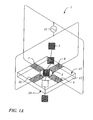
Referring now to FIG. 1A, a first embodiment of the invention is depicted. The
first electrode 7, the second electrode 8, the third electrode 9 and the fourth electrode 10
are all positioned on the top surface 17 of the substrate 12 adjacent to the nanopore 3. The
electrode 7 is positioned adjacent to the electrode 8. The electrode 8 is positioned
adjacent to the electrode 9. The electrode 9 is positioned adjacent to the electrode 10.
Each of the electrodes 7-10 is positioned in the same plane adjacent to the nanopore 3.
As described above, the electrode 7 and the electrode 9 are electrically connected to
define a first set of electrodes. In addition, the electrode 8 and the electrode 10 are
electrically connected to define a second set of electrodes.
Referring now to FIG. 1B, a second embodiment of the invention is shown. In this
embodiment of the invention, additional electrodes are employed on substrate 12. The
additional electrodes include a fifth electrode 7', a sixth electrode 8' adjacent to the fifth
electrode 7', a seventh electrode 9' adjacent to the sixth electrode 8' and an eighth
electrode 10' adjacent to the seventh electrode 9'. Electrodes 7', 8', 9' and 10' may
comprise, be part of or be attached to the substrate 12. In this embodiment of the
invention electrodes 7',8', 9' and 10'are positioned on the bottom surface 19 of substrate
12 adjacent to the nanopore 3, wherein each of said electrodes is positioned adjacent to
said nanopore 3 to create a quadrupole field through the length of said nanopore 3. The
first electrode 7 is electrically connected to the fifth electrode 7'. The second electrode 8
is electrically connected to the sixth electrode 8'. The third electrode 9 is electrically
connected to the seventh electrode 9'. The fourth electrode 10 is electrically connected to
the eighth electrode 10'. Similar to the design above, the electrodes 7,7' are electrically
connected to the 9,9' electrodes to define a first set of electrodes. In addition, the 8,8' and
10, 10' electrodes are electrically connected to define a second set of electrodes.
Referring now to FIGS. 2A and 2B, further embodiments of the present invention
are depicted. These embodiments are similar to FIGS. 1A and 1B, but contain a second
voltage source 15 coupled to a current measuring device 13 for monitoring quantum
tunneling through opposing electrodes and for detection of portions of the biopolymer 5.
The second voltage source 15 and current measuring device 13 may be used to monitor
quantum tunneling in either a static voltage or ramped voltage mode.
Having now described the apparatus of the invention in detail, a discussion of the
method is now in order. The method of the present invention provides a method for
controlling the lateral movement of a biopolymer as it translocates a nanopore. The
method comprises applying a DC voltage and radio frequency voltage to a first set of
electrodes, applying an opposite DC voltage and phase shifted radio frequency voltage to
a second set of electrodes to produce an electric field between the first set of electrodes
and the second set of electrodes, and controlling the movement of a biopolymer using the
electric field as the biopolymer translocates a nanopore. How the actual apparatus and
method prevent the lateral movement of a biopolymer will now be described in greater
detail.
It is well known that an RF-quadrupole field can be used to focus and guide a
charged particle along a specified propagation direction. A typical application of this
phenomenon is in the area of mass spectrometry, where devices employing RF-quadrupole
fields guide particles of specified charge-to-mass ratios down a propagation
channel, and cause particles of different charge-to-mass ratios to be expelled from this
region. The specified charge-to-mass ratio is determined by the geometry and parameters
of the RF-field. In a typical device, four rods form a quadrupole field in cross-section. As
described further in the Appendix, for appropriate parameter choice, the RF field
produces an effective potential that tends to force the charged particle toward the central
axis. If there are not dissipative effects, the particle travels down this axis with an
oscillatory transverse motion under the effects of the transverse effective harmonic
potential. If there are dissipative effects, as the particle travels down the propagation axis,
the transverse oscillations are damped out, and the trajectory smoothly settles on the axis.
It is possible to exploit this physical phenomenon to control biopolymers that are
translocating a nanopore, and smoothly guide them to the center of the pore. FIGS. 1-2
show the apparatus of the present invention that is used to implement this effect. The set
of four electrodes is used to create an approximate quadrupole field in the nanopore
opening. The RF-field parameters (to be discussed later) are chosen to guide particles
with the charge-to-mass ratio of the biopolymers. The effective potential generated
provides a continuous force guiding the translocating strand to the center of the nanopore.
This mitigates the set of problems catalogued above. In particular, restriction of lateral
movement allows an unimpeded uniform translocation, as well as symmetric and
controlled tunneling current environment. It should be noted that optionally, a DC
tunneling voltage can be superimposed upon an opposing pair of electrodes that
contribute to generating the quadrupole field.
A physical system that consists of a charged bipolymer strand passing through an
RF quadruple field, which is of limited extent in the propagation direction, is clearly
different from the physical systems described by the prior art. However, it is equally clear
that the physical mechanisms generating the effective restoring forces that guide the
moving particle toward the axis are the same. Equations (A6) and (A7) in the Appendix
describe the transverse forces on the charged particle or a segment of a charged
biopolymer strand. For the single particle, it describes the transverse forces as it travels
down the length of the device. For the biopolymer, it describes the restoring force
exhibited on the moving strand at a fixed spatial point.
Equation (A10) can be used to estimate the RF-voltage parameters required to
have the effective forces generate net focusing for a biopolymer strand. Assuming that
the DC voltage is zero (a u = 0), it is seen from the stability plot (FIG. 4), that it is
required that qu < 0.91 to have stable trajectories, or net focusing
0.91 > qu = 4e mr 2 0Ω2 V
where e is the electronic charge, m is the effective mass of the relevant portion of the
biopolymer strand, r0 is the radius of the quadrupole aperture, Ω and V are the angular
frequency and amplitude of the RF voltage, respectively. The current nanopores would
support an r0 of approximately 10 angstroms. A typical nucleotide base has a mass of
roughly 400 amu, although the effective mass for a base that is part of a continuous
strand would be significantly larger, and depend upon the rigidity of the total structure.
For estimation purposes it will be assumed that the effective mass is approximately five
times that of an individual base. With these parameter values, the requirement for
stability (focusing) as expressed in the equation (1) is given by
V F 2 < 2 × 10⁻¹⁰
where V is given in volts and F is the RF frequency in MHz. For an applied RF frequency
of 1.0 GHz, the quadruple would tend to guide the polynucleotide strand toward the
center of the nanopore for an RF voltage amplitude satisfying the constraint
V ≤ 200 µ V.
The RF-voltage parameters are achievable for the configurations previously described.
The present invention is designed to obviate the previously discussed problems. When
operated in the guiding (stable) mode, the quadrupole fields force the biopolymer toward
the center of the nanopore. This mitigates the problem of non-uniform translocation
events due to intermittent interaction of the biopolymer with the nanopore walls. It also
greatly improves the detection of the portion of the biopolymer being analyzed by
minimizing the effects of variable ionic current flow due to random changes in the shape
of the partially blocked pore. These random changes are largely due to lateral offsets of
the biopolymer during translocation. For an electron tunneling detection scheme,
confining the biopolymer to the center of the nanopore will eliminate the potentially large
swings in the magnitude of the measured current by minimizing the variability of the
proximity of the biopolymer to the tunneling electrodes.
Another use of the present invention quadrupole structure is based upon operating
the quadrupole with parameters chosen to have the strand dynamics to be in the unstable
regime, as defined in FIG. 4. For the parameters specified in the example described
above, this would correspond to adjusting the amplitude of the RF-voltage above the
level of the equation (3), i.e.
V > 200 µV.
For this voltage, the lateral motion of the translocating biopolymer would be
unstable, forcing it away from the center of the nanopore. For appropriate parameter
choices, this would "pin" the biopolymer against the wall of the nanopore. Depending
upon the structure of the nanopore walls, this could cause the translocation process to be
halted in a controlled fashion. This ability to stop and resume translocation of the
biopolymer in a controlled way has a number of useful applications. It could be used to
slow down the rate of translocation, allowing more time for the base detection
measurements. It could also be used to hold a portion of the biopolymer in place while
the measurement was allowed to focus on one particular portion of the biopolymer.
Although the invention is shown in FIG. 1 and FIG. 2, the invention is not limited
to these particular embodiments. Other embodiments and structures are possible. For
instance, the electrodes may have any generalized shape that produces approximate
quadruple fields in the nanopore. Also, to increase the length of the region over which
the quadrupole -biopolymer interaction occurs, multiple electrode sets can be employed.
For example, electrode sets can be used on both sides of the nanopore, causing the
quadrupole field to be more accurately maintained over the entire length of the nanopore.
Additionally, higher multipole fields can be used, such as octupole fields. These
embodiments have stability diagrams similar to the one described above and can be
exploited in similar ways. This is the case even if the stability diagrams of these
embodiments are less sharply defined.
Example 1
An example of the described device could be fabricated using techniques known
to those skilled in the art. For instance, the nanopore can be made in a thin (500 nm)
freestanding silicon nitride (SiN3) membrane supported on a silicon frame. Using a
focused Ion Beam (FIB) machine, a single initial pore of roughly 500 nM diameter can be
created in the membrane. Then, illumination of the pore region with a beam of 3 KeV
Argon ion sputters material and slowly closes the hole to the desired dimension of
roughly 2 nM in diameter (See Li et al., Nature, 412: 166-169, 2001). Metal electrodes
are formed by patterning and evaporation, or other deposition means, to generate the
quadrupole structure. Wire bonding to the metal electrodes allows connection to the RF
voltage source. The RF voltage source has the modest requirements of several hundred
microvolts at a frequency of 1.0 GHz.
Example 2
A second example of the present invention would be similar to the first, however,
and additional set of four electrodes are deposited on the opposing face of the substrate.
The second set of electrodes are wired bonded in parallel to the RF voltage source,
allowing coherent generation of the quadruple fields over the length of the nanopore.
APPENDIX
In order to understand the use of RF-quadrupole fields to control polymer
translocation through a nanopore, it is best to review the phenomenon in a related and
familiar system. In the first section of the Appendix, RF-quadrupole basics are reviewed
and discussed in terms of traditional mass spectrometry applications. In the second
section, the intuitive underpinnings of the physical effects are explained by analogy to an
optical system consisting of alternating focusing and de-focusing lenses. In the third
section, the RF-quadrupole effective potential is derived.
A1. RF-quadrupole basics
A typical RF-quadrupole application in the area of mass spectrometry employs a
set of four parallel rod electrodes. The quadrupole fields are translationally invariant
along the direction of the ion trajectories. In cross section, the shapes of the equipotential
surfaces can be easily determined. The cross sectional two dimensional potentials have
the form
= 0 r 2 0 (x 2 - y 2)
where the definitions of the parameters are given in the Figure 3. The fields are uniform
along the z-axis, except for the regions near the end of the rods, which will be neglected
for this discussion.
The force on an ion with mass
m and charge
e from these fields is given by
which has the component form
where a "dot" denotes differentiation with respect to time. If the applied potential is
generalized to
include DC and RF components
0 = U - Vcos (Ωt),
then the equations of motion become
These equations can be written in a canonical form, defining ξ = Ω
t/2,
∂2 u ∂ξ2 + (au - 2qu cos(2ξ)) u = 0
which is recognized as the standard form of the much-studied Mathieu equation. For
u =
x
ax = 8 e mr 2 0Ω2 U
qx = 4e mr 2 0Ω2 V
and for
u =
y
ay = -8e mr 2 0Ω2 U
qy = -4e mr 2 0Ω2 V. Detailed discussions of the solutions of equation (A8) can be found in the
literature (See Morse and Freshbach, Methods of Theoretical Physics," McGraw-Hill,
New York (1953). For certain ranges of the parameters au and qu the solutions are
oscillatory and stable, and for the other regions the solutions are unstable, exhibiting
exponential growth with time. Figure 4 shows the stable and unstable ranges of the
parameters for equation (A8) in the region near the origin of parameter space. It is clear
that, depending upon the voltages U and V, the RF frequency Ω, the field scale factor r0,
and the ion charge-to-mass ratio e/m, the ions will have stable (propagating) or unstable
(non-propagating) trajectories as they travel down the RF-quadrupole device. This
physical effect is exploited in mass spectrometry, to make instruments that selectively
pass specified charge-to-mass ratio ions. The devices are tuned to the desired charge-to-mass
ration by the adjustment of any combination of the voltage parameters.
A2. Physical basis of RF-Quadrupole operation and ion trajectories
At first glance, it may seem surprising that the Mathieu equation has solutions that
are oscillatory and stable. Specifically, looking at one of the component dynamical
equations for an ion in the quadrupole f
ields
for V>U, it is clearly seen that the restoring field is alternately positive (focusing) and
negative (de-focusing). It is not obvious that for certain parameter choices the final effect
can be net focusing.
To understand how this alternating focusing/de-focusing field of an RF-quadrupole
can give stable and focused trajectories is best accomplished by investigating
an analogous optical system. It is well known that a system of alternately focusing
(converging) and de-focusing (diverging) lenses can create an optical structure that
focuses and guides and optical beam. A property of lenses is that the refractive focusing
(de-focusing) of a converging (diverging) lens is proportional to the distance of the ray
from the optical propagation axis. As a result, a wide beam incident on a series of
alternately focusing and defocusing lenses is strongly refracted toward the propagation
axis as it passes through the first converging lens. As it passes through the next lens,
which is diverging, it is less strongly refracted away from the propagation axis because
its offset is relatively smaller than what it was as it passed through the first lens.
Similarly, it passes through the next lens, which is converging, it is more strongly
refracted back toward the propagation axis than it was refracted away from the
propagation axis by the previous lens because its offset is now relatively larger. It is clear
that the net effect of this optical system is focusing of the input beam for appropriately
chosen lenses and separations.
A3. RF-guadrupole effective potential
To gain further insight into the dynamics of the Mathieu equation,
∂ 2 u ∂ξ2 + (au - 2qu cos(2ξ)) u = 0,
It is instructive to generate solutions by numerical integration for a range of parameters
within the stability region. A typical solution has the form shown in Figure 5. The motion
has two fundamental components. There is a smaller faster component which is at the
frequency of the RF-drive voltage, referred to as the "micromotion" and a larger slower
component which is reflective of the interaction of the ion with the time-averaged
effective potential, referred to as the "macromotion." Denoting the micromotion
component by 8 and the macromotion component by R, the displacement takes the form
u ≡ R + δ.
It is assumed that δ « R, but dδ / dt » dR / dt. Plugging equation (A 15) into (A 14), and keeping only the
leading terms
d 2δ d 2ξ = - (au - 2qu cos(2ξ)) R.
For au « qu, and R approximately constant over a period of the RF,
δ = - qu 2 cos(2ξ) R,
which implies
u ≈ R - qu 2 cos (2ξ) R.
The Mathieu equation (A14) becomes
Averaging equation (A19) over a period of the RF-drive yields
which can be written in real units as
Equation (A21) describes the effective dynamics for the time-averaged macromotion of an ion in
an RF-guadrupole field. Its solutions are simple harmonic functions, in response to an effective
potential which generates a harmonic restoring force. This effective restoring force pulls the ions
toward the axis of symmetry at the center of the quadruple field region.