EP1445047A2 - A method for spray forming metal deposits - Google Patents
A method for spray forming metal deposits Download PDFInfo
- Publication number
- EP1445047A2 EP1445047A2 EP04100341A EP04100341A EP1445047A2 EP 1445047 A2 EP1445047 A2 EP 1445047A2 EP 04100341 A EP04100341 A EP 04100341A EP 04100341 A EP04100341 A EP 04100341A EP 1445047 A2 EP1445047 A2 EP 1445047A2
- Authority
- EP
- European Patent Office
- Prior art keywords
- spray
- spraying
- metal particles
- temperature
- value
- Prior art date
- Legal status (The legal status is an assumption and is not a legal conclusion. Google has not performed a legal analysis and makes no representation as to the accuracy of the status listed.)
- Granted
Links
- 238000000034 method Methods 0.000 title claims abstract description 40
- 229910052751 metal Inorganic materials 0.000 title claims abstract description 37
- 239000002184 metal Substances 0.000 title claims abstract description 37
- 238000009718 spray deposition Methods 0.000 title claims abstract description 20
- 238000005507 spraying Methods 0.000 claims abstract description 50
- 239000002923 metal particle Substances 0.000 claims abstract description 38
- 230000002045 lasting effect Effects 0.000 claims abstract description 4
- 239000007921 spray Substances 0.000 claims description 58
- 239000000758 substrate Substances 0.000 claims description 30
- 239000000919 ceramic Substances 0.000 claims description 14
- 239000000463 material Substances 0.000 abstract description 8
- 239000007789 gas Substances 0.000 description 7
- 238000005266 casting Methods 0.000 description 3
- -1 i.e. Substances 0.000 description 3
- 239000002002 slurry Substances 0.000 description 3
- IJGRMHOSHXDMSA-UHFFFAOYSA-N Atomic nitrogen Chemical compound N#N IJGRMHOSHXDMSA-UHFFFAOYSA-N 0.000 description 2
- 229910000881 Cu alloy Inorganic materials 0.000 description 2
- 238000000889 atomisation Methods 0.000 description 2
- 230000015572 biosynthetic process Effects 0.000 description 2
- 238000010891 electric arc Methods 0.000 description 2
- 230000008018 melting Effects 0.000 description 2
- 238000002844 melting Methods 0.000 description 2
- 238000007750 plasma spraying Methods 0.000 description 2
- 239000000843 powder Substances 0.000 description 2
- 230000037303 wrinkles Effects 0.000 description 2
- 229910000838 Al alloy Inorganic materials 0.000 description 1
- 229910001369 Brass Inorganic materials 0.000 description 1
- 229910000906 Bronze Inorganic materials 0.000 description 1
- 229910000975 Carbon steel Inorganic materials 0.000 description 1
- RYGMFSIKBFXOCR-UHFFFAOYSA-N Copper Chemical compound [Cu] RYGMFSIKBFXOCR-UHFFFAOYSA-N 0.000 description 1
- 239000004593 Epoxy Substances 0.000 description 1
- 229910001128 Sn alloy Inorganic materials 0.000 description 1
- 229910000831 Steel Inorganic materials 0.000 description 1
- HCHKCACWOHOZIP-UHFFFAOYSA-N Zinc Chemical compound [Zn] HCHKCACWOHOZIP-UHFFFAOYSA-N 0.000 description 1
- 229910001297 Zn alloy Inorganic materials 0.000 description 1
- 230000001133 acceleration Effects 0.000 description 1
- 230000001154 acute effect Effects 0.000 description 1
- 229910052782 aluminium Inorganic materials 0.000 description 1
- 239000004411 aluminium Substances 0.000 description 1
- XAGFODPZIPBFFR-UHFFFAOYSA-N aluminium Chemical compound [Al] XAGFODPZIPBFFR-UHFFFAOYSA-N 0.000 description 1
- 239000010951 brass Substances 0.000 description 1
- 239000010974 bronze Substances 0.000 description 1
- 239000010962 carbon steel Substances 0.000 description 1
- 239000011248 coating agent Substances 0.000 description 1
- 238000000576 coating method Methods 0.000 description 1
- 239000002131 composite material Substances 0.000 description 1
- 239000010949 copper Substances 0.000 description 1
- KUNSUQLRTQLHQQ-UHFFFAOYSA-N copper tin Chemical compound [Cu].[Sn] KUNSUQLRTQLHQQ-UHFFFAOYSA-N 0.000 description 1
- 230000003247 decreasing effect Effects 0.000 description 1
- 230000008021 deposition Effects 0.000 description 1
- 238000005474 detonation Methods 0.000 description 1
- 238000001035 drying Methods 0.000 description 1
- 238000005516 engineering process Methods 0.000 description 1
- QFXZANXYUCUTQH-UHFFFAOYSA-N ethynol Chemical group OC#C QFXZANXYUCUTQH-UHFFFAOYSA-N 0.000 description 1
- 239000000945 filler Substances 0.000 description 1
- 238000010304 firing Methods 0.000 description 1
- 238000005242 forging Methods 0.000 description 1
- 239000000446 fuel Substances 0.000 description 1
- 229910001092 metal group alloy Inorganic materials 0.000 description 1
- 150000002739 metals Chemical class 0.000 description 1
- 239000000203 mixture Substances 0.000 description 1
- 229910052757 nitrogen Inorganic materials 0.000 description 1
- 239000002245 particle Substances 0.000 description 1
- 238000005096 rolling process Methods 0.000 description 1
- 238000000926 separation method Methods 0.000 description 1
- 239000010935 stainless steel Substances 0.000 description 1
- 229910001220 stainless steel Inorganic materials 0.000 description 1
- 239000010959 steel Substances 0.000 description 1
- 238000010257 thawing Methods 0.000 description 1
- 238000010290 vacuum plasma spraying Methods 0.000 description 1
- 238000003466 welding Methods 0.000 description 1
- 239000011701 zinc Substances 0.000 description 1
- 229910052725 zinc Inorganic materials 0.000 description 1
Images

Classifications
-
- B—PERFORMING OPERATIONS; TRANSPORTING
- B22—CASTING; POWDER METALLURGY
- B22F—WORKING METALLIC POWDER; MANUFACTURE OF ARTICLES FROM METALLIC POWDER; MAKING METALLIC POWDER; APPARATUS OR DEVICES SPECIALLY ADAPTED FOR METALLIC POWDER
- B22F3/00—Manufacture of workpieces or articles from metallic powder characterised by the manner of compacting or sintering; Apparatus specially adapted therefor ; Presses and furnaces
- B22F3/115—Manufacture of workpieces or articles from metallic powder characterised by the manner of compacting or sintering; Apparatus specially adapted therefor ; Presses and furnaces by spraying molten metal, i.e. spray sintering, spray casting
-
- C—CHEMISTRY; METALLURGY
- C23—COATING METALLIC MATERIAL; COATING MATERIAL WITH METALLIC MATERIAL; CHEMICAL SURFACE TREATMENT; DIFFUSION TREATMENT OF METALLIC MATERIAL; COATING BY VACUUM EVAPORATION, BY SPUTTERING, BY ION IMPLANTATION OR BY CHEMICAL VAPOUR DEPOSITION, IN GENERAL; INHIBITING CORROSION OF METALLIC MATERIAL OR INCRUSTATION IN GENERAL
- C23C—COATING METALLIC MATERIAL; COATING MATERIAL WITH METALLIC MATERIAL; SURFACE TREATMENT OF METALLIC MATERIAL BY DIFFUSION INTO THE SURFACE, BY CHEMICAL CONVERSION OR SUBSTITUTION; COATING BY VACUUM EVAPORATION, BY SPUTTERING, BY ION IMPLANTATION OR BY CHEMICAL VAPOUR DEPOSITION, IN GENERAL
- C23C4/00—Coating by spraying the coating material in the molten state, e.g. by flame, plasma or electric discharge
- C23C4/12—Coating by spraying the coating material in the molten state, e.g. by flame, plasma or electric discharge characterised by the method of spraying
Definitions
- This invention generally relates to methods for producing prototype tools and in particular to methods for spray forming metal deposits.
- Spray forming has become an accepted technique for producing prototype tooling, i.e., dies and moulds, in substantially less time than needed to make prototype tooling conventionally.
- the typical spray forming technique includes the following steps: (1) casting a ceramic substrate containing a spraying pattern about a mould containing a master pattern of the tool to be produced; (2) preheating the ceramic substrate; (3) spraying metal particles onto the substrate containing the spraying pattern; (4) allowing the sprayed metal particles to form a metal deposit having the general shape of the master pattern; and (5) separating the metal deposit from the ceramic substrate.
- thermal gradients can form across the thin shell.
- the formation of thermal gradients can be largely attributed to the following factors: (1) the difference between the temperature of the spraying pattern and the deposited metal particles, and (2) the superior insulating properties of the ceramic substrate.
- the ceramic substrate is preheated to about 250°C.
- the temperature of the thin shell and spraying pattern can typically reach temperatures of about 350°C. The significant amount of heat associated with these temperatures is not dissipated through the ceramic substrate due to its superior insulating properties. Most of the heat generated by the sprayed metal particles is contained in the metal deposit.
- the significant thermal gradients can cause the thin shell to separate from the spraying pattern, causing surface imperfections, i.e., wrinkles and/or cracks, in the metal deposit.
- the surface imperfections have to be corrected with additional processing steps so that the metal deposit is suitable for prototype tooling.
- a welding material can be (1) welded onto the surface imperfection, and (2) ground to reflect the general shape characteristics of the master pattern.
- the surface imperfection can be smoothed and filled with a filler material, i.e., metal filled epoxy. In some cases, the surface imperfections are so extreme that the metal deposit is unsuitable for prototype tooling and must be scrapped.
- a method for spray forming metal deposits characterised in that the method comprises providing a substrate having a spraying pattern for receiving sprayed metal particles, spraying metal particles onto the spraying pattern to form a metal deposit on the spraying pattern for at least a first spray period and controlling the spraying step during the first spray period so that the temperature of the deposited metal particles increase at an average rate of less than or equal to about 15°C per minute.
- the substrate may be comprised of a ceramic substrate.
- the controlling of the spraying step during the first spray period comprises using at least one thermal gun to spray metal particles.
- the current supplied to the at least one thermal spray gun may be increased from a first ampere value towards a second ampere value during the first spray period.
- the first ampere value may be about 150 amperes and the second ampere value may be about 220 amperes.
- the at least one thermal spray gun may be fed with wire and the wire feed rate of the at least one thermal spray gun may be increased from a first value to a second value during the first spray period.
- the first value may be about 6.75kg of wire per hour and the second value may be about 10kg of wire per hour.
- the first spray period may last until the temperature of the deposited metal particles is at or about a steady state temperature.
- the steady state temperature may be about 330°C to about 370°C.
- the method may further comprise spraying metal particles onto the metal deposit for at least a second spray period lasting longer than the first spray period and being conducted at about the steady state temperature.
- the first spray period may last until the thickness of the metal deposit is about 1 millimetre thick.
- One embodiment of the present invention provides a method comprising at least three basic steps: (a) providing a substrate having a spraying pattern for receiving sprayed metal particles, (b) spraying metal particles onto the spraying pattern to form a metal deposit on the spraying pattern for at least a first spray period, the first spray period lasting until the temperature of the deposited metal particles reaches a steady state temperature, and (c) controlling the spraying step during the first spray period so that the temperature of the deposited metal particles increases at an average rate of less than or equal to about 15°C per minute.
- the substrate 12, shown schematically in Figure 1 is preferably a ceramic substrate produced using a freeze-casting process.
- One typical freeze-casting process includes the following steps: (1) pouring a slurry into the mould containing a master pattern, (2) lowering the temperature of the slurry to freeze the slurry and form the ceramic substrate containing the spraying pattern, (3) extracting the substrate from the mould, (4) thawing the ceramic substrate, and (5) drying the ceramic substrate during the firing cycle. After completing step (5), the spraying pattern is ready to receive sprayed metal particles.
- metal particles are sprayed onto the spraying pattern using spray forming.
- materials suitable for being sprayed using spray forming include, but are not limited to, pure metals, i.e., zinc, aluminium, and copper, and metal alloys, i.e., tin alloys, zinc alloys, aluminium alloys, copper alloys, bronze, steel, brass, and stainless steel.
- a particularly preferred material for spray forming is 0.8 carbon steel, available from Praxir Surface Technologies of Indianapolis, Indiana. It should be understood that spray forming can refer to any technique used to deposit metal particles upon a substrate.
- Spray forming techniques that can be used in accord with the present invention include, but are not limited to spray-rolling, spray-forging, centrifugal spray-casting, spray-casting, spray-peening, splat-coating, particle composite deposition, roller atomizing, modified arc spray, and modified plasma-spraying.
- thermal spray gun(s) 14 are preferably utilized to spray metal particles 16 onto the spraying pattern of substrate 12.
- Thermal spray gun 14 can be of the oxy-acetylene flame type in which a wire or powder metal is fed there into, a plasma-type into which powder metal is fed, or preferably one or two wire arc type, in which the tip of the wires is fed into the arc.
- high-energy plasma-spraying, vacuum plasma-spraying, detonation, and high-velocity oxy-fuel techniques can be utilized.
- an electric arc is generated in a zone between two consumable wire electrodes; as the electrodes melt, the arc is maintained by continuously feeding the electrodes into the arc zone.
- the metal at the electrode tips is atomized by a blast of generally cold compressed gas. The atomized metal is then propelled by the gas jet to a substrate forming a deposit thereon.
- a single wire is fed either through the central axis of the torch or is fed at an acute angle into a plasma stream that is generated internally within the torch.
- the thickness of the wire used in the typical spray forming operation is preferably in the range of about 1.6 to 3.2mm and most preferably about 1.6mm.
- the single wire acts as a consumable electrode that is fed into the arc chamber.
- the arc is established between the cathode of the plasma torch and the single wire as an anode, thereby melting the tip of the wire.
- Gas is fed into the arc chamber, coaxially to the cathode, where it is expanded by the electric arc to cause a highly heated gas stream (carrying metal droplets from the electrode tip) to flow through the nozzle.
- a further higher temperature gas flow may be used to shroud or surround the spray of molten metal so that droplets are subjected to further atomization and acceleration.
- wire arc torch guns may be utilized that use a transferred-arc plasma whereby an initial arc is struck between a cathode and a nozzle surrounding the cathode; the plasma created from such arc is transferred to a secondary anode (outside the gun nozzle) in the form of a single or double wire feedstock causing melting of the tip of such wire feedstock.
- a thermal spray gun 14 has a gun tip 18 which is oriented along an axis 20 perpendicular to the general planar extent of the base of the freeze-case substrate.
- the thermal spray gun 14 has a power supply 22 that can be operated at about 30 volts and a current of about 50 amperes to about 350 amperes.
- Thermal spray gun 14 is supplied with a high pressure gas from their respective supplies consisting of nitrogen, air, or a mixture thereof, at a pressure of about 275kPa to about 827kPa (40 to about 120 p.s.i). The gas is used to affect the atomization of the wire droplets.
- the metal particles are sprayed onto the spraying pattern for at least a first spray period and a second spray period.
- the first spray period begins when spraying beings and lasts until the temperature of the deposited metal particles reaches about a steady state temperature.
- the second spray period begins when the temperature of the deposited metal particles reaches about the steady state temperature and lasts until spraying ends.
- the temperature of the deposited metal is at or near the steady state temperature during the second spray period. For the majority of the total spray period, the temperature of the deposited metal particles is at or near the steady state temperature.
- the steady state temperature is preferably between about 330°C and 370°C, and most preferably about 350°C.
- substrate 12 Prior to spraying the metal particles onto the spraying pattern, substrate 12 can be pre-heated to affect suitable adhesion characteristics.
- the ceramic substrate can be preheated to about 250°C.
- the adhesion of the sprayed metal particles onto the spraying pattern depends on the temperature of the deposited metal particles. The temperature of the deposited metal particles is largely dependant upon the operating parameters (i.e., supplied amperage or wire feed rate) of thermal spray gun(s).
- the spray step is controlled during the first spray period to minimize surface imperfections.
- Figure 2 is a graph that depicts the temperature of the deposited metal particles as a function of spraying time for two different spray forming processes A and B.
- Process A is a prior art process that commonly leads to surface imperfections.
- Process B is an example of an improved process that minimizes surface imperfections.
- Curve A of Figure 2 depicts the temperature of the deposited metal particles as a function of spraying time for process A.
- the operating parameters of the thermal spray gun(s) are set to achieve a desired ramp rate for the initial metal deposit.
- the amperage of the thermal gun(s) can be set to about 170 amperes, or alternatively, the wire feed rate can be set to about 7.7kg per hour (17 pounds/hour). It should be understood that the amperes and feed rates can vary depending on several parameters, i.e., substrate size, amount of guns, spray pattern geometry, pre-heat temperature, and deposit efficiency.
- the operating parameters of the thermal spray gun(s) are adjusted to increase the deposited metal temperature to the steady state temperature.
- the amperage of the thermal gun(s) can be adjusted from about 170 amperes to about 220 amperes, or alternatively, the wire feed rate can be adjusted from about 6.75 to 10kg per hour (15 pounds/hour to about 22 pounds/hour).
- the first spray period begins at about point C and ends at about point D, and lasts about 5 minutes.
- the second spray period begins at about point D and lasts until the spraying process is completed.
- Process A can produce surface imperfections in the metal deposit during the initial stages of spraying due to the significant stress created by significant thermal gradients across the metal deposit. Correcting the surface imperfections can require additional process steps in order to make the deposit suitable for prototype tooling. In extreme cases, the surface imperfections are so severe that the metal deposit is scrapped.
- Curve B depicts the temperature of the deposited metal particles as a function of spraying time for a preferred embodiment of the present invention.
- the operating parameters of the thermal spray gun(s) are set to achieve a desired ramp rate for the initial metal deposit.
- the amperage of the thermal gun(s) can be set to about 150 amperes, or alternatively, the wire feed rate can be set to about 6.75kg per hour (15 pounds/hour).
- the amperage of the thermal gun(s) can be adjusted from about 150 amperes to about 220 amperes, or alternatively, the wire feed rate can be adjusted from about 6.75 to 10kg per hour (15 pounds/hour to about 22 pounds/hour).
- the first spray period begins at about point C and ends at about point E, and lasts about 10 minutes. Therefore, the average ramp rate for the first spray period is about 10°C per minute of spraying time.
- a second spray period starts at point E and continues until the desired thickness of material has been deposited which normally is longer than the time taken to reach the steady state temperature. Material is then deposited at the steady state temperature until the required thickness is achieved.
- the average ramp rate of the first spray period can be about 15°C per minute in order to reduce the occurrences of surface imperfections depending on operating conditions.
- the ranges of operating parameter ramping values, i.e., amperes and wire feed rates, to deliver the ramp rates suitable for minimizing surface imperfections can vary depending on several parameters, i.e., substrate size, amount of guns, spray pattern geometry, preheating temperature, and deposit efficiency. It will be further understood that the spraying process could continue until a predetermined thickness of material such as 1 mm has been deposited on the substrate rather than when a steady state temperature has been reached.
Abstract
Description
- This invention generally relates to methods for producing prototype tools and in particular to methods for spray forming metal deposits.
- Spray forming has become an accepted technique for producing prototype tooling, i.e., dies and moulds, in substantially less time than needed to make prototype tooling conventionally. The typical spray forming technique includes the following steps: (1) casting a ceramic substrate containing a spraying pattern about a mould containing a master pattern of the tool to be produced; (2) preheating the ceramic substrate; (3) spraying metal particles onto the substrate containing the spraying pattern; (4) allowing the sprayed metal particles to form a metal deposit having the general shape of the master pattern; and (5) separating the metal deposit from the ceramic substrate.
- During the early stages of the spraying step, a thin shell of sprayed metal is deposited onto the spraying pattern. Significant thermal gradients can form across the thin shell. The formation of thermal gradients can be largely attributed to the following factors: (1) the difference between the temperature of the spraying pattern and the deposited metal particles, and (2) the superior insulating properties of the ceramic substrate. Typically, the ceramic substrate is preheated to about 250°C. During the initial stages of the spraying step, the temperature of the thin shell and spraying pattern can typically reach temperatures of about 350°C. The significant amount of heat associated with these temperatures is not dissipated through the ceramic substrate due to its superior insulating properties. Most of the heat generated by the sprayed metal particles is contained in the metal deposit.
- The significant thermal gradients can cause the thin shell to separate from the spraying pattern, causing surface imperfections, i.e., wrinkles and/or cracks, in the metal deposit. After separating the metal deposit from the ceramic substrate, the surface imperfections have to be corrected with additional processing steps so that the metal deposit is suitable for prototype tooling. For example, a welding material can be (1) welded onto the surface imperfection, and (2) ground to reflect the general shape characteristics of the master pattern. As another example, the surface imperfection can be smoothed and filled with a filler material, i.e., metal filled epoxy. In some cases, the surface imperfections are so extreme that the metal deposit is unsuitable for prototype tooling and must be scrapped.
- It is an object of this invention to provide an improved method for spray forming metal deposits that minimizes the formation of surface imperfections.
- According to the invention there is provided a method for spray forming metal deposits characterised in that the method comprises providing a substrate having a spraying pattern for receiving sprayed metal particles, spraying metal particles onto the spraying pattern to form a metal deposit on the spraying pattern for at least a first spray period and controlling the spraying step during the first spray period so that the temperature of the deposited metal particles increase at an average rate of less than or equal to about 15°C per minute.
- The substrate may be comprised of a ceramic substrate.
- The controlling of the spraying step during the first spray period comprises using at least one thermal gun to spray metal particles.
- The current supplied to the at least one thermal spray gun may be increased from a first ampere value towards a second ampere value during the first spray period.
- The first ampere value may be about 150 amperes and the second ampere value may be about 220 amperes.
- The at least one thermal spray gun may be fed with wire and the wire feed rate of the at least one thermal spray gun may be increased from a first value to a second value during the first spray period.
- The first value may be about 6.75kg of wire per hour and the second value may be about 10kg of wire per hour.
- The first spray period may last until the temperature of the deposited metal particles is at or about a steady state temperature.
- The steady state temperature may be about 330°C to about 370°C.
- The method may further comprise spraying metal particles onto the metal deposit for at least a second spray period lasting longer than the first spray period and being conducted at about the steady state temperature.
- Alternatively, the first spray period may last until the thickness of the metal deposit is about 1 millimetre thick.
- The invention will now be described by way of example with reference to the accompanying drawing of which:-
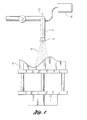
- Figure 1 is a schematic illustration of an apparatus used in a spray forming process of the present invention; and
- Figure 2 is a graph that depicts the temperature of deposited metal particles as a function of spraying time for two different spray forming processes (A) and (B).
-
- As required, detailed embodiments of the present invention are disclosed herein. However, it is to be understood that the disclosed embodiments are merely exemplary of the invention that may be embodied in various and alternative forms. The figures are not necessarily to scale and some features may be exaggerated or minimized to show details of particular components. Therefore, specific structural and functional details disclosed herein are not to be interpreted as limiting, but merely as a representative basis for the claims and/or as a representative basis for teaching one skilled in the art to variously employ the present invention.
- One embodiment of the present invention provides a method comprising at least three basic steps: (a) providing a substrate having a spraying pattern for receiving sprayed metal particles, (b) spraying metal particles onto the spraying pattern to form a metal deposit on the spraying pattern for at least a first spray period, the first spray period lasting until the temperature of the deposited metal particles reaches a steady state temperature, and (c) controlling the spraying step during the first spray period so that the temperature of the deposited metal particles increases at an average rate of less than or equal to about 15°C per minute.
- The
substrate 12, shown schematically in Figure 1, is preferably a ceramic substrate produced using a freeze-casting process. One typical freeze-casting process includes the following steps: (1) pouring a slurry into the mould containing a master pattern, (2) lowering the temperature of the slurry to freeze the slurry and form the ceramic substrate containing the spraying pattern, (3) extracting the substrate from the mould, (4) thawing the ceramic substrate, and (5) drying the ceramic substrate during the firing cycle. After completing step (5), the spraying pattern is ready to receive sprayed metal particles. - In accordance with a preferred embodiment of the present invention, metal particles are sprayed onto the spraying pattern using spray forming. Examples of materials suitable for being sprayed using spray forming include, but are not limited to, pure metals, i.e., zinc, aluminium, and copper, and metal alloys, i.e., tin alloys, zinc alloys, aluminium alloys, copper alloys, bronze, steel, brass, and stainless steel. A particularly preferred material for spray forming is 0.8 carbon steel, available from Praxir Surface Technologies of Indianapolis, Indiana. It should be understood that spray forming can refer to any technique used to deposit metal particles upon a substrate. Spray forming techniques that can be used in accord with the present invention include, but are not limited to spray-rolling, spray-forging, centrifugal spray-casting, spray-casting, spray-peening, splat-coating, particle composite deposition, roller atomizing, modified arc spray, and modified plasma-spraying.
- As shown schematically in Figure 1, one or more thermal spray gun(s) 14 are preferably utilized to spray
metal particles 16 onto the spraying pattern ofsubstrate 12.Thermal spray gun 14 can be of the oxy-acetylene flame type in which a wire or powder metal is fed there into, a plasma-type into which powder metal is fed, or preferably one or two wire arc type, in which the tip of the wires is fed into the arc. In addition, high-energy plasma-spraying, vacuum plasma-spraying, detonation, and high-velocity oxy-fuel techniques can be utilized. - In a two wire arc spray gun, an electric arc is generated in a zone between two consumable wire electrodes; as the electrodes melt, the arc is maintained by continuously feeding the electrodes into the arc zone. The metal at the electrode tips is atomized by a blast of generally cold compressed gas. The atomized metal is then propelled by the gas jet to a substrate forming a deposit thereon.
- In a single wire arc apparatus, a single wire is fed either through the central axis of the torch or is fed at an acute angle into a plasma stream that is generated internally within the torch. The thickness of the wire used in the typical spray forming operation is preferably in the range of about 1.6 to 3.2mm and most preferably about 1.6mm. The single wire acts as a consumable electrode that is fed into the arc chamber. The arc is established between the cathode of the plasma torch and the single wire as an anode, thereby melting the tip of the wire. Gas is fed into the arc chamber, coaxially to the cathode, where it is expanded by the electric arc to cause a highly heated gas stream (carrying metal droplets from the electrode tip) to flow through the nozzle. A further higher temperature gas flow may be used to shroud or surround the spray of molten metal so that droplets are subjected to further atomization and acceleration.
- Yet still other wire arc torch guns may be utilized that use a transferred-arc plasma whereby an initial arc is struck between a cathode and a nozzle surrounding the cathode; the plasma created from such arc is transferred to a secondary anode (outside the gun nozzle) in the form of a single or double wire feedstock causing melting of the tip of such wire feedstock.
- In the preferred embodiment shown in Figure 1, a
thermal spray gun 14 has agun tip 18 which is oriented along anaxis 20 perpendicular to the general planar extent of the base of the freeze-case substrate. Thethermal spray gun 14 has apower supply 22 that can be operated at about 30 volts and a current of about 50 amperes to about 350 amperes.Thermal spray gun 14 is supplied with a high pressure gas from their respective supplies consisting of nitrogen, air, or a mixture thereof, at a pressure of about 275kPa to about 827kPa (40 to about 120 p.s.i). The gas is used to affect the atomization of the wire droplets. - According to a preferred embodiment of the present invention, the metal particles are sprayed onto the spraying pattern for at least a first spray period and a second spray period. The first spray period begins when spraying beings and lasts until the temperature of the deposited metal particles reaches about a steady state temperature. The second spray period begins when the temperature of the deposited metal particles reaches about the steady state temperature and lasts until spraying ends. The temperature of the deposited metal is at or near the steady state temperature during the second spray period. For the majority of the total spray period, the temperature of the deposited metal particles is at or near the steady state temperature. The steady state temperature is preferably between about 330°C and 370°C, and most preferably about 350°C.
- Prior to spraying the metal particles onto the spraying pattern,
substrate 12 can be pre-heated to affect suitable adhesion characteristics. For instance, the ceramic substrate can be preheated to about 250°C. In addition to the preheating temperature, the adhesion of the sprayed metal particles onto the spraying pattern depends on the temperature of the deposited metal particles. The temperature of the deposited metal particles is largely dependant upon the operating parameters (i.e., supplied amperage or wire feed rate) of thermal spray gun(s). - According to a preferred embodiment, the spray step is controlled during the first spray period to minimize surface imperfections. Figure 2 is a graph that depicts the temperature of the deposited metal particles as a function of spraying time for two different spray forming processes A and B. Process A is a prior art process that commonly leads to surface imperfections. Process B is an example of an improved process that minimizes surface imperfections.
- Curve A of Figure 2 depicts the temperature of the deposited metal particles as a function of spraying time for process A. At point C on curve A, the operating parameters of the thermal spray gun(s) are set to achieve a desired ramp rate for the initial metal deposit. For example, the amperage of the thermal gun(s) can be set to about 170 amperes, or alternatively, the wire feed rate can be set to about 7.7kg per hour (17 pounds/hour). It should be understood that the amperes and feed rates can vary depending on several parameters, i.e., substrate size, amount of guns, spray pattern geometry, pre-heat temperature, and deposit efficiency. Before reaching point D on curve A, the operating parameters of the thermal spray gun(s) are adjusted to increase the deposited metal temperature to the steady state temperature. For example, the amperage of the thermal gun(s) can be adjusted from about 170 amperes to about 220 amperes, or alternatively, the wire feed rate can be adjusted from about 6.75 to 10kg per hour (15 pounds/hour to about 22 pounds/hour).
- The first spray period begins at about point C and ends at about point D, and lasts about 5 minutes. The second spray period begins at about point D and lasts until the spraying process is completed.
- Process A can produce surface imperfections in the metal deposit during the initial stages of spraying due to the significant stress created by significant thermal gradients across the metal deposit. Correcting the surface imperfections can require additional process steps in order to make the deposit suitable for prototype tooling. In extreme cases, the surface imperfections are so severe that the metal deposit is scrapped.
- It has been discovered that by increasing the spraying time necessary to reach the steady state temperature relative to the prior art, surface imperfections can be minimized. In other words, the rate at which the temperature of the deposited metal increases over spraying time is decreased. The adjustment greatly reduces the amount of separation, and therefore the amount of cracks and wrinkles that form during the initial stages of the spray forming process.
- Curve B depicts the temperature of the deposited metal particles as a function of spraying time for a preferred embodiment of the present invention. At point C on curve B, the operating parameters of the thermal spray gun(s) are set to achieve a desired ramp rate for the initial metal deposit. For example, the amperage of the thermal gun(s) can be set to about 150 amperes, or alternatively, the wire feed rate can be set to about 6.75kg per hour (15 pounds/hour). Before reaching point E on curve B, i.e., reaching the steady state temperature, the amperage of the thermal gun(s) can be adjusted from about 150 amperes to about 220 amperes, or alternatively, the wire feed rate can be adjusted from about 6.75 to 10kg per hour (15 pounds/hour to about 22 pounds/hour). The first spray period begins at about point C and ends at about point E, and lasts about 10 minutes. Therefore, the average ramp rate for the first spray period is about 10°C per minute of spraying time.
- A second spray period starts at point E and continues until the desired thickness of material has been deposited which normally is longer than the time taken to reach the steady state temperature. Material is then deposited at the steady state temperature until the required thickness is achieved.
- It should be understood that the average ramp rate of the first spray period can be about 15°C per minute in order to reduce the occurrences of surface imperfections depending on operating conditions. It should be understood that the ranges of operating parameter ramping values, i.e., amperes and wire feed rates, to deliver the ramp rates suitable for minimizing surface imperfections can vary depending on several parameters, i.e., substrate size, amount of guns, spray pattern geometry, preheating temperature, and deposit efficiency. It will be further understood that the spraying process could continue until a predetermined thickness of material such as 1 mm has been deposited on the substrate rather than when a steady state temperature has been reached.
- While the best mode for carrying out the invention has been described in detail, those familiar with the art to which this invention relates will recognize various alternative designs and embodiments for practicing the invention as defined by the following claims.
Claims (11)
- A method for spray forming metal deposits characterised in that the method comprises providing a substrate (12) having a spraying pattern for receiving sprayed metal particles (16), spraying metal particles (16) onto the spraying pattern to form a metal deposit on the spraying pattern for at least a first spray period and controlling the spraying step during the first spray period so that the temperature of the deposited metal particles increase at an average rate of less than or equal to about 15°C per minute.
- A method as claimed claim 1 wherein the substrate is comprised of a ceramic substrate (12).
- A method as claimed claim 1 or in claim 2 wherein the controlling of the spraying step during the first spray period comprises using at least one thermal gun (14) to spray metal particles.
- A method as claimed claim 3 wherein the current supplied to the at least one thermal spray gun (14) is increased from a first ampere value towards a second ampere value during the first spray period.
- A method as claimed claim 4 wherein the first ampere value is about 150 amperes and the second ampere value is about 220 amperes.
- A method as claimed in any of claims 3 to 5 wherein the at least one thermal spray gun (14) is fed with wire and the wire feed rate of the at least one thermal spray gun (14) is increased from a first value to a second value during the first spray period.
- A method as claimed claim 6 wherein the first value is about 6.75kg of wire per hour and the second value is about 10kg of wire per hour.
- A method as claimed in any of claims 1 to 7 wherein the first spray period lasts until the temperature of the deposited metal particles is at or about a steady state temperature.
- A method as claimed claim 8 wherein the steady state temperature is about 330°C to about 370°C.
- A method as claimed claim 8 or in claim 9 wherein the method further comprises spraying metal particles onto the metal deposit for at least a second spray period lasting longer than the first spray period and being conducted at about the steady state temperature.
- A method as claimed in any of claims 1 to 7 wherein the first spray period lasts until the thickness of the metal deposit is about 1 millimetre thick.
Applications Claiming Priority (2)
| Application Number | Priority Date | Filing Date | Title |
|---|---|---|---|
| US10/248,692 US6777035B1 (en) | 2003-02-10 | 2003-02-10 | Method for spray forming metal deposits |
| US248692 | 2003-02-10 |
Publications (3)
| Publication Number | Publication Date |
|---|---|
| EP1445047A2 true EP1445047A2 (en) | 2004-08-11 |
| EP1445047A3 EP1445047A3 (en) | 2006-05-24 |
| EP1445047B1 EP1445047B1 (en) | 2019-06-19 |
Family
ID=32654174
Family Applications (1)
| Application Number | Title | Priority Date | Filing Date |
|---|---|---|---|
| EP04100341.9A Expired - Lifetime EP1445047B1 (en) | 2003-02-10 | 2004-01-30 | A method for spray forming metal deposits |
Country Status (2)
| Country | Link |
|---|---|
| US (1) | US6777035B1 (en) |
| EP (1) | EP1445047B1 (en) |
Cited By (1)
| Publication number | Priority date | Publication date | Assignee | Title |
|---|---|---|---|---|
| CN103600072A (en) * | 2012-12-26 | 2014-02-26 | 机械科学研究总院先进制造技术研究中心 | Multi-metal liquid injection deposition material-increase manufacturing device |
Families Citing this family (7)
| Publication number | Priority date | Publication date | Assignee | Title |
|---|---|---|---|---|
| US20060269685A1 (en) * | 2005-05-31 | 2006-11-30 | Honeywell International, Inc. | Method for coating turbine engine components with high velocity particles |
| GB2447486A (en) * | 2007-03-14 | 2008-09-17 | Sandvik Osprey Ltd | A brazing piece comprising a composite material including an inorganic flux |
| US20090026175A1 (en) * | 2007-07-26 | 2009-01-29 | Honeywell International, Inc. | Ion fusion formation process for large scale three-dimensional fabrication |
| US8287966B2 (en) * | 2007-10-10 | 2012-10-16 | GM Global Technology Operations LLC | Spray cast mixed-material vehicle closure panels |
| US9205488B2 (en) * | 2011-06-30 | 2015-12-08 | Persimmon Technologies Corporation | Structured magnetic material having domains with insulated boundaries |
| US9162290B2 (en) * | 2013-04-04 | 2015-10-20 | Caterpillar Inc. | Center spacer between workpiece and dead center of machine tool |
| CN103894610B (en) * | 2014-04-18 | 2017-03-01 | 机械科学研究总院先进制造技术研究中心 | A kind of controllable temperature forming platform system |
Citations (4)
| Publication number | Priority date | Publication date | Assignee | Title |
|---|---|---|---|---|
| US5952056A (en) * | 1994-09-24 | 1999-09-14 | Sprayform Holdings Limited | Metal forming process |
| US6155330A (en) * | 1998-11-04 | 2000-12-05 | Visteon Global Technologies, Inc. | Method of spray forming metal deposits using a metallic spray forming pattern |
| US6257309B1 (en) * | 1998-11-04 | 2001-07-10 | Ford Global Technologies, Inc. | Method of spray forming readily weldable and machinable metal deposits |
| US6329022B1 (en) * | 1997-07-28 | 2001-12-11 | Volkswagen Ag | Connecting rod with a high strength bearing layer |
Family Cites Families (3)
| Publication number | Priority date | Publication date | Assignee | Title |
|---|---|---|---|---|
| GB9016985D0 (en) | 1990-08-02 | 1990-09-19 | Sprayforming Dev Ltd | An improved method of producing tools and dies |
| US5718863A (en) | 1992-11-30 | 1998-02-17 | Lockheed Idaho Technologies Company | Spray forming process for producing molds, dies and related tooling |
| US6805188B2 (en) * | 2001-04-18 | 2004-10-19 | Ford Global Technologies, Llc | Method and arrangement for heat treatment before the execution of sprayform techniques |
-
2003
- 2003-02-10 US US10/248,692 patent/US6777035B1/en not_active Expired - Lifetime
-
2004
- 2004-01-30 EP EP04100341.9A patent/EP1445047B1/en not_active Expired - Lifetime
Patent Citations (4)
| Publication number | Priority date | Publication date | Assignee | Title |
|---|---|---|---|---|
| US5952056A (en) * | 1994-09-24 | 1999-09-14 | Sprayform Holdings Limited | Metal forming process |
| US6329022B1 (en) * | 1997-07-28 | 2001-12-11 | Volkswagen Ag | Connecting rod with a high strength bearing layer |
| US6155330A (en) * | 1998-11-04 | 2000-12-05 | Visteon Global Technologies, Inc. | Method of spray forming metal deposits using a metallic spray forming pattern |
| US6257309B1 (en) * | 1998-11-04 | 2001-07-10 | Ford Global Technologies, Inc. | Method of spray forming readily weldable and machinable metal deposits |
Cited By (2)
| Publication number | Priority date | Publication date | Assignee | Title |
|---|---|---|---|---|
| CN103600072A (en) * | 2012-12-26 | 2014-02-26 | 机械科学研究总院先进制造技术研究中心 | Multi-metal liquid injection deposition material-increase manufacturing device |
| CN103600072B (en) * | 2012-12-26 | 2016-12-28 | 机械科学研究总院先进制造技术研究中心 | Many metal liquids jet deposition increases material and manufactures equipment |
Also Published As
| Publication number | Publication date |
|---|---|
| EP1445047A3 (en) | 2006-05-24 |
| US6777035B1 (en) | 2004-08-17 |
| EP1445047B1 (en) | 2019-06-19 |
| US20040157001A1 (en) | 2004-08-12 |
Similar Documents
| Publication | Publication Date | Title |
|---|---|---|
| EP1092497B1 (en) | Method for repairing spray-formed steel tooling | |
| EP2236211A1 (en) | Plasma transfer wire arc thermal spray system | |
| US3064114A (en) | Apparatus and process for spraying molten metal | |
| US6470954B2 (en) | Method of spray forming readily weldable and machinable metal deposits | |
| KR920005786B1 (en) | Thermal spray coating having improved addherence low residual stress and improved resistance to spalling and method for producing same | |
| JPH07317595A (en) | Covering method of automobile engine cylinder | |
| JPH0474423B2 (en) | ||
| EP1445047B1 (en) | A method for spray forming metal deposits | |
| JPH02177284A (en) | Manufacture of ignition plug electrode | |
| US20140154422A1 (en) | Plasma spraying process | |
| US6155330A (en) | Method of spray forming metal deposits using a metallic spray forming pattern | |
| US6810939B2 (en) | Spray formed articles made of boron steel and method for making the same | |
| Talib et al. | Thermal spray coating technology: A review | |
| US6308765B1 (en) | Method of making tools having a core die and a cavity die | |
| TWI677589B (en) | A preparation method of sputtering target | |
| EP1092496B1 (en) | Method for repairing steel spray-formed tooling with TIG welding process | |
| US6358466B1 (en) | Thermal sprayed composite melt containment tubular component and method of making same | |
| US20130011569A1 (en) | Method and device for arc spraying | |
| US6833165B2 (en) | Thermally sprayed coatings | |
| CN112280336B (en) | Anti-oxidation coating material for high-temperature large-deformation steel and preparation method thereof | |
| GB2294227A (en) | The production of an article using a thermal spray technique | |
| US20150060413A1 (en) | Wire alloy for plasma transferred wire arc coating processes | |
| JPH0139993B2 (en) | ||
| CN115003850A (en) | Method and apparatus for metal coating of bore walls | |
| JPS6315343B2 (en) |
Legal Events
| Date | Code | Title | Description |
|---|---|---|---|
| PUAI | Public reference made under article 153(3) epc to a published international application that has entered the european phase |
Free format text: ORIGINAL CODE: 0009012 |
|
| AK | Designated contracting states |
Kind code of ref document: A2 Designated state(s): AT BE BG CH CY CZ DE DK EE ES FI FR GB GR HU IE IT LI LU MC NL PT RO SE SI SK TR |
|
| AX | Request for extension of the european patent |
Extension state: AL LT LV MK |
|
| PUAL | Search report despatched |
Free format text: ORIGINAL CODE: 0009013 |
|
| AK | Designated contracting states |
Kind code of ref document: A3 Designated state(s): AT BE BG CH CY CZ DE DK EE ES FI FR GB GR HU IE IT LI LU MC NL PT RO SE SI SK TR |
|
| AX | Request for extension of the european patent |
Extension state: AL LT LV MK |
|
| RIC1 | Information provided on ipc code assigned before grant |
Ipc: B22F 3/115 20060101ALI20060401BHEP Ipc: C23C 4/12 20060101AFI20060401BHEP |
|
| 17P | Request for examination filed |
Effective date: 20061023 |
|
| AKX | Designation fees paid |
Designated state(s): DE FR GB |
|
| 17Q | First examination report despatched |
Effective date: 20091221 |
|
| STAA | Information on the status of an ep patent application or granted ep patent |
Free format text: STATUS: EXAMINATION IS IN PROGRESS |
|
| GRAP | Despatch of communication of intention to grant a patent |
Free format text: ORIGINAL CODE: EPIDOSNIGR1 |
|
| STAA | Information on the status of an ep patent application or granted ep patent |
Free format text: STATUS: GRANT OF PATENT IS INTENDED |
|
| INTG | Intention to grant announced |
Effective date: 20190130 |
|
| GRAS | Grant fee paid |
Free format text: ORIGINAL CODE: EPIDOSNIGR3 |
|
| GRAA | (expected) grant |
Free format text: ORIGINAL CODE: 0009210 |
|
| STAA | Information on the status of an ep patent application or granted ep patent |
Free format text: STATUS: THE PATENT HAS BEEN GRANTED |
|
| AK | Designated contracting states |
Kind code of ref document: B1 Designated state(s): DE FR GB |
|
| REG | Reference to a national code |
Ref country code: GB Ref legal event code: FG4D |
|
| REG | Reference to a national code |
Ref country code: DE Ref legal event code: R096 Ref document number: 602004054061 Country of ref document: DE |
|
| REG | Reference to a national code |
Ref country code: DE Ref legal event code: R097 Ref document number: 602004054061 Country of ref document: DE |
|
| PLBE | No opposition filed within time limit |
Free format text: ORIGINAL CODE: 0009261 |
|
| STAA | Information on the status of an ep patent application or granted ep patent |
Free format text: STATUS: NO OPPOSITION FILED WITHIN TIME LIMIT |
|
| 26N | No opposition filed |
Effective date: 20200603 |
|
| PGFP | Annual fee paid to national office [announced via postgrant information from national office to epo] |
Ref country code: GB Payment date: 20221214 Year of fee payment: 20 Ref country code: FR Payment date: 20221216 Year of fee payment: 20 |
|
| PGFP | Annual fee paid to national office [announced via postgrant information from national office to epo] |
Ref country code: DE Payment date: 20221215 Year of fee payment: 20 |
|
| P01 | Opt-out of the competence of the unified patent court (upc) registered |
Effective date: 20230620 |
|
| REG | Reference to a national code |
Ref country code: DE Ref legal event code: R071 Ref document number: 602004054061 Country of ref document: DE |
|
| REG | Reference to a national code |
Ref country code: GB Ref legal event code: PE20 Expiry date: 20240129 |