EP1446334B1 - Low profile inflatable package protection system - Google Patents
Low profile inflatable package protection system Download PDFInfo
- Publication number
- EP1446334B1 EP1446334B1 EP02798447A EP02798447A EP1446334B1 EP 1446334 B1 EP1446334 B1 EP 1446334B1 EP 02798447 A EP02798447 A EP 02798447A EP 02798447 A EP02798447 A EP 02798447A EP 1446334 B1 EP1446334 B1 EP 1446334B1
- Authority
- EP
- European Patent Office
- Prior art keywords
- inflatable
- perimeter
- layer
- layers
- spaced
- Prior art date
- Legal status (The legal status is an assumption and is not a legal conclusion. Google has not performed a legal analysis and makes no representation as to the accuracy of the status listed.)
- Expired - Lifetime
Links
- 238000004806 packaging method and process Methods 0.000 claims abstract description 47
- 239000012530 fluid Substances 0.000 claims 4
- 239000010410 layer Substances 0.000 description 96
- 230000002093 peripheral effect Effects 0.000 description 29
- 239000003779 heat-resistant material Substances 0.000 description 10
- 238000007789 sealing Methods 0.000 description 5
- 230000000694 effects Effects 0.000 description 4
- 230000015572 biosynthetic process Effects 0.000 description 3
- 238000010276 construction Methods 0.000 description 3
- 230000007423 decrease Effects 0.000 description 3
- 239000000463 material Substances 0.000 description 2
- 230000004048 modification Effects 0.000 description 2
- 238000012986 modification Methods 0.000 description 2
- 230000037361 pathway Effects 0.000 description 2
- 238000003466 welding Methods 0.000 description 2
- 230000000996 additive effect Effects 0.000 description 1
- 238000002788 crimping Methods 0.000 description 1
- 230000003247 decreasing effect Effects 0.000 description 1
- 239000000945 filler Substances 0.000 description 1
- 238000002347 injection Methods 0.000 description 1
- 239000007924 injection Substances 0.000 description 1
- 239000005022 packaging material Substances 0.000 description 1
- 239000003973 paint Substances 0.000 description 1
- 239000013047 polymeric layer Substances 0.000 description 1
- 238000004904 shortening Methods 0.000 description 1
- 239000011800 void material Substances 0.000 description 1
Images


Classifications
-
- B—PERFORMING OPERATIONS; TRANSPORTING
- B32—LAYERED PRODUCTS
- B32B—LAYERED PRODUCTS, i.e. PRODUCTS BUILT-UP OF STRATA OF FLAT OR NON-FLAT, e.g. CELLULAR OR HONEYCOMB, FORM
- B32B21/00—Layered products comprising a layer of wood, e.g. wood board, veneer, wood particle board
- B32B21/04—Layered products comprising a layer of wood, e.g. wood board, veneer, wood particle board comprising wood as the main or only constituent of a layer, which is next to another layer of the same or of a different material
- B32B21/08—Layered products comprising a layer of wood, e.g. wood board, veneer, wood particle board comprising wood as the main or only constituent of a layer, which is next to another layer of the same or of a different material of synthetic resin
-
- B—PERFORMING OPERATIONS; TRANSPORTING
- B65—CONVEYING; PACKING; STORING; HANDLING THIN OR FILAMENTARY MATERIAL
- B65D—CONTAINERS FOR STORAGE OR TRANSPORT OF ARTICLES OR MATERIALS, e.g. BAGS, BARRELS, BOTTLES, BOXES, CANS, CARTONS, CRATES, DRUMS, JARS, TANKS, HOPPERS, FORWARDING CONTAINERS; ACCESSORIES, CLOSURES, OR FITTINGS THEREFOR; PACKAGING ELEMENTS; PACKAGES
- B65D81/00—Containers, packaging elements, or packages, for contents presenting particular transport or storage problems, or adapted to be used for non-packaging purposes after removal of contents
- B65D81/02—Containers, packaging elements, or packages, for contents presenting particular transport or storage problems, or adapted to be used for non-packaging purposes after removal of contents specially adapted to protect contents from mechanical damage
- B65D81/05—Containers, packaging elements, or packages, for contents presenting particular transport or storage problems, or adapted to be used for non-packaging purposes after removal of contents specially adapted to protect contents from mechanical damage maintaining contents at spaced relation from package walls, or from other contents
- B65D81/051—Containers, packaging elements, or packages, for contents presenting particular transport or storage problems, or adapted to be used for non-packaging purposes after removal of contents specially adapted to protect contents from mechanical damage maintaining contents at spaced relation from package walls, or from other contents using pillow-like elements filled with cushioning material, e.g. elastic foam, fabric
- B65D81/052—Containers, packaging elements, or packages, for contents presenting particular transport or storage problems, or adapted to be used for non-packaging purposes after removal of contents specially adapted to protect contents from mechanical damage maintaining contents at spaced relation from package walls, or from other contents using pillow-like elements filled with cushioning material, e.g. elastic foam, fabric filled with fluid, e.g. inflatable elements
-
- Y—GENERAL TAGGING OF NEW TECHNOLOGICAL DEVELOPMENTS; GENERAL TAGGING OF CROSS-SECTIONAL TECHNOLOGIES SPANNING OVER SEVERAL SECTIONS OF THE IPC; TECHNICAL SUBJECTS COVERED BY FORMER USPC CROSS-REFERENCE ART COLLECTIONS [XRACs] AND DIGESTS
- Y10—TECHNICAL SUBJECTS COVERED BY FORMER USPC
- Y10S—TECHNICAL SUBJECTS COVERED BY FORMER USPC CROSS-REFERENCE ART COLLECTIONS [XRACs] AND DIGESTS
- Y10S206/00—Special receptacle or package
- Y10S206/821—Stacking member
-
- Y—GENERAL TAGGING OF NEW TECHNOLOGICAL DEVELOPMENTS; GENERAL TAGGING OF CROSS-SECTIONAL TECHNOLOGIES SPANNING OVER SEVERAL SECTIONS OF THE IPC; TECHNICAL SUBJECTS COVERED BY FORMER USPC CROSS-REFERENCE ART COLLECTIONS [XRACs] AND DIGESTS
- Y10—TECHNICAL SUBJECTS COVERED BY FORMER USPC
- Y10T—TECHNICAL SUBJECTS COVERED BY FORMER US CLASSIFICATION
- Y10T428/00—Stock material or miscellaneous articles
- Y10T428/13—Hollow or container type article [e.g., tube, vase, etc.]
- Y10T428/1334—Nonself-supporting tubular film or bag [e.g., pouch, envelope, packet, etc.]
-
- Y—GENERAL TAGGING OF NEW TECHNOLOGICAL DEVELOPMENTS; GENERAL TAGGING OF CROSS-SECTIONAL TECHNOLOGIES SPANNING OVER SEVERAL SECTIONS OF THE IPC; TECHNICAL SUBJECTS COVERED BY FORMER USPC CROSS-REFERENCE ART COLLECTIONS [XRACs] AND DIGESTS
- Y10—TECHNICAL SUBJECTS COVERED BY FORMER USPC
- Y10T—TECHNICAL SUBJECTS COVERED BY FORMER US CLASSIFICATION
- Y10T428/00—Stock material or miscellaneous articles
- Y10T428/13—Hollow or container type article [e.g., tube, vase, etc.]
- Y10T428/1352—Polymer or resin containing [i.e., natural or synthetic]
Definitions
- valve 32 may be formed with third layer 34 connected to an outer surface 35 of first layer 14.
- second layer 16 is connected to surface 37 of first layer 14 opposite the outer surface 35 of first layer 14.
- edge 36 of third layer 34 is sealed relative to the edge of first layer 14 along perimeter heat seal segment 18a.
- a heat seal further connects edges 40 and 42 of third layer 34 to first layer 14.
- Edge 44 of third layer 34 is sealed relative to first layer 14 with the exception of the small peripheral section 20 that defines an inflation medium inlet, as previously described.
- FIG. 14 A second alternative embodiment of system 100 is shown in FIG. 14. As shown in FIG. 14, system 100 is in a deflated state. Each heat seal 110 that separates adjacent cells 102 is provided with a central cut 130 that extends between seal 108 and seal 112. This central cut 130 permits each cell 102 to individually reduce in width W as cells 102 are inflated, such that a gap between adjacent cells 102 forms along cut 130. Thus, cut 130 relieves the strain along seal 108 and prevents header 104 from buckling.
Abstract
Description
- The present invention generally relates to inflatable packaging. In particular, the present invention relates to low profile inflatable packaging systeins with improved perimeter protection, integrity and inflatability.
- Inflatable packaging systems having opposing inflatable members sealed relative to one another to form an envelope like package are known to provide protection for relatively flat items being shipped or otherwise transported. The known inflatable packaging systems, however, do not provide ample perimeter protection for such items. There is a need for an inflatable envelope-like packaging system with improved perimeter protection.
- Check valves for a single inflatable member are known. Also known are inflatable packaging systems having multiple inflatable cells. There is a continuing need for check valves that can be easily incorporated into each inflatable cell of a multiple cell packaging system to ensure the integrity of the packaging system in the event of a leak in one region of the packaging.
- Inflatable packaging systems having multiple cells that extend transverse from a common inflation header are subject to inflation difficulties. As the cells fill with inflation medium, the width of each cell decreases. The additive effect of multiple cells inflating and decreasing in width causes a strain on the seal separating the cells from the inflation header. The result of this strain is a buckling of the inflation header that can inhibit or even prevent an inflation medium from traveling to cells distant from the point of buckling. There is a need for a multi-cell inflatable packaging system that improves the flow path for an inflation medium through a header to the multiple cells.
- Further from JP 11 236075 A an air bag is known which has a gas injection port in communication with the outside air which is partitioned into a plurality of small air bags formed side by side which are alternatingly fed with air from two directions.
- The air bag has the disadvantage, that in case a breach occur in one area of the air bag the integrity of the entire system is lost.
- The inflatable member of the present invention has all the features of
claim 1 and, more generally is comprised of first and second film layers that overly one another and are sealed relative to one another about their respective perimeters with the exception of a gap that allows for the introduction of an inflation medium into an interior defined between the first and second film layers. A fill valve is connected within the gap. The first and second film layers are further interconnected by a first seal that is spaced from and extends around a portion of the perimeter. This first seal defines a perimeter inflatable channel, with a first section of the perimeter channel in communication with the fill valve. A plurality of separate inflatable cells are formed between the first section of the perimeter channel and a second section of the perimeter channel by a plurality of spaced second seals of the first and second film layers. The plurality of spaced second seals extend transversely from a portion of the first seal along the first section of the perimeter channel. Each cell of the plurality of inflatable cells communicates with the first section of the perimeter channel. -
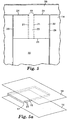
- FIG. 1 is a top schematic view of an inflatable member of the present invention.
- FIG. 2 is an exploded perspective view of the film layer orientation for the inflatable member of FIG. 1.
- FIG. 2a is a cross-sectional view of the inflatable member of FIG. 1 taken along
line 2a-2a of FIG. 1. - FIG. 3 is a top schematic view of an alternative embodiment of the inflatable member of the present invention.
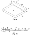
- FIG. 4 is an exploded perspective view of the film layer orientation for the inflatable member of FIG. 3.
- FIG. 4a is a cross-sectional view of the inflatable member of FIG. 3 taken along
line 4a-4a of FIG. 3. - FIG. 5 is an enlarged cutaway view of an inflatable cell of the inflatable member of the present invention with an alternative valve configuration.
- FIG. 5a is an exploded perspective view of the film layer orientation for forming the valve of FIG. 5.
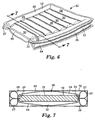
- FIG. 6 is a perspective view of a packaging system formed from two inflatable members of FIG. 1.
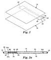
- FIG. 7 is a cross-sectional view of the packaging system of FIG. 6 taken along line 7-7 of FIG. 6.
- FIG. 8 is a schematic end view of an alternative packaging system configuration formed from two inflatable members of the present invention.
- FIG. 9 is a schematic cross-sectional view of the alternative packaging system of FIG. 8.
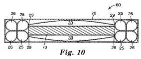
- FIG. 10 is a cross-sectional view of the packaging system of FIG. 6 with enhanced perimeter protection.
- FIG. 11 is an enlarged schematic cutaway view of a segment of the inflatable member of FIG. 1 incorporating pleats in the peripheral inflatable chamber.
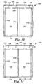
- FIG. 12 is a partial top schematic view of an alternative multi-cell packaging system of the present invention
- FIG. 13 is a first alternative embodiment of the packaging system of FIG. 12.
- FIG. 14 is a second alternative embodiment of the packaging system of FIG. 12.
- FIGS. 15 and 16 are cross-sectional views of alternate constructions of the packaging systems of FIGS. 12-14 utilizing a one way valve of FIGS. 5-5a.
- While the above-identified drawing figures set forth preferred embodiments of the invention, other embodiments are also contemplated, as noted in the discussion. In all cases, this disclosure presents the present invention by way of representation and not limitation. It should be understood that numerous other modifications and embodiments can be devised by those skilled in the art which fall within the scope and spirit of the principles of this invention. It should be specifically noted that the figures have not been drawn to scale as it has been necessary to enlarge certain portions for clarity. Throughout the embodiments, like reference numerals are used for like elements.
-
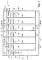
Packaging system 10 of the present invention is generally shown in FIG. 1.Packaging system 10 is comprised of aninflatable member 12 formed of overlaying first andsecond layers 14 and 16 (See FIG. 2) of a flexible polymeric material. Opposing peripheral edge surfaces oflayers perimeter heat seal 18. A smallperipheral section 20 oflayers check valve 22, such as is commonly known in the art. Suitable check valves are disclosed, for example, in U.S. Patent Nos. 4,917,646 and 5,711,691. - Spaced from
perimeter heat seal 18 along three sides ofinflatable member 12, aheat seal 24interconnects layers inflatable chamber 26 ofinflatable member 12, withinflation valve 22 communicating with afirst section 27 ofinflatable chamber 26.Layers heat seals 28, which extends betweenheat seal segments inflatable cells 30 ofinflatable member 12 ofpackaging system 10. Eachinflatable cell 30 communicates withfirst section 27 ofinflatable chamber 26, such as via an interruption ofheat seal segment 24a. - As further shown in FIGS. 1-2a, in one preferred embodiment,
inflatable cells 30 and asecond section 29 of peripheralinflatable chamber 26 include a oneway valve system 32 to retain air in the respective cell and/or chamber oncepackaging system 10 is inflated. Oneway valve 32 is formed by connecting a third polymeric layer 34 (shown in FIGS. 2-2a) tofirst layer 14 with a series of heat seals which will be further described herein. - In one preferred embodiment,
valve 32 is formed by positioningthird layer 34 betweenfirst layer 14 andsecond layer 16.Third layer 34 has a length, defined byedges second layers third layer 34 has a width, defined byopposing end edges second layers spacing edge 36 ofthird layer 34 from peripheralheat seal segment 18a.Edge 36 is then sealed relative tofirst layer 14 andsecond layer 16 byheat seal segment 24a.Heat seal segment 24a completely sealsedge 36 ofthird layer 34 tosecond layer 16. At intervals corresponding to eachinflatable cell 30 andsecond section 29 ofinflatable chamber 26, however, one of the opposing surfaces of eitherfirst layer 14 orthird layer 34 is treated with a heat resistant material (e.g., ink or paint) alongheat seal segment 24a to prevent heat sealing at the treated sites and thereby defineair inlets 38. -
Edge 40 ofthird layer 34 is connected tofirst layer 14 by a heat seal that spans inflatable cells 30 (interrupted byoutlets 48 as described below). Opposing end edges 42 and 44 ofthird layer 34 are interconnected by heat seal tofirst layer 14 andsecond layer 16 along the perimeterheat seal segments Third layer 34 is further connected tofirst layer 14 with a series of heat welds 46 which are generally parallel to and spaced fromheat seal segment 24a and edge 40 ofthird layer 34. One of the opposing surfaces of eitherthird layer 34 orfirst layer 14 is further treated with heat resistant material to prevent welding ofthird layer 34 andfirst layer 14 at discreet locations along eachheat weld 46 to create a serpentine-like flow path for an inflation medium frominlets 38. Each serpentine-like flow path terminates at anoutlet 48 that communicates with an interior ofinflatable member 12.Outlets 48 are formed by treating a portion of eitherfirst layer 14 orthird layer 34 adjacent to edge 40 with a heat resistant material, as previously described. -
Inflatable member 12 ofpackaging system 10 is inflated by applying air throughinflation valve 22. Thefirst section 27 of peripheralinflatable chamber 26 communicates withvalve 32 viainlet 38. Air flows from peripheralinflatable chamber 26 through eachinlet 38 and the respective serpentine flow path defined by segmented heat welds 46 and enters eachinflatable cell 30 andsection 29 of peripheralinflatable chamber 26 viaoutlets 48. Asinflatable cells 30 andsection 29 of peripheralinflatable chamber 26 achieve their maximum inflation, the internal pressure ofinflatable cell 30 andinflatable chamber 26 causes opposing surfaces ofthird layer 34 andfirst layer 14 to tightly bear against one another and thereby prevent air from escapinginflatable cell 30 and peripheralinflatable chamber 26. - As shown in FIGS. 3- 4a, in an alternative embodiment,
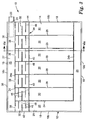
valve 32 may be formed withthird layer 34 connected to anouter surface 35 offirst layer 14. In this embodiment,second layer 16 is connected to surface 37 offirst layer 14 opposite theouter surface 35 offirst layer 14. As shown in FIGS. 3- 4a, edge 36 ofthird layer 34 is sealed relative to the edge offirst layer 14 along perimeterheat seal segment 18a. A heat seal further connectsedges third layer 34 tofirst layer 14.Edge 44 ofthird layer 34 is sealed relative tofirst layer 14 with the exception of the smallperipheral section 20 that defines an inflation medium inlet, as previously described. -
Second layer 16 is dimensioned to have a length defined by perimeterheat seal segments heat seal segment 24a and perimeterheat seal segment 18d. The perimeter edges ofsecond layer 16 are connected tofirst layer 14 byheat seal segments Heat seal segment 24a also connectsfirst layer 14 andthird layer 34, withinlets 38 being formed by treating a portion of eitherfirst layer 14 orthird layer 34 with a heat resistant material at intervals corresponding to eachcell 30 to prevent sealing of adjacent surfaces offirst layer 14 andthird layer 34 whenheat seal segment 24a is formed. Heat welds 46, as described relative to FIG. 1, interconnectthird layer 34 tofirst layer 14 to form the serpentine flow path ofvalve 32.Outlets 48, however, in the embodiment shown in FIG. 3, are formed by an opening throughfirst layer 14 near the end of the serpentine flow path, as shown in FIG. 4a. As previously described, wheninflatable cells 30 andsection 29 of peripheralinflatable chamber 26 achieve their maximum inflation, the internal pressure ofinflatable cell 30 andinflatable chamber 26 causes opposing surfaces ofthird layer 34 andfirst layer 14 to tightly bear against one another and thereby prevent air from escapinginflatable cell 30 and peripheralinflatable chamber 26. - FIG. 5 depicts an alternative embodiment of one
way valve 32 for use withpackaging system 10. FIG. 5 is an enlarged cutaway view of one ofinflatable cells 30. As shown in FIGS. 5 and 5a, the alternative configuration ofvalve 32 consists of a pair of film layers 15 and 17 positioned betweenfirst layer 14 andsecond layer 16.Layers valve 32 are sealed relative to one another and to first andsecond layers layers zone 19 to prevent heat sealing and thereby define an air inlet ofvalve 32. Heat seals 21 further interconnect layers 15 and 17 to define aflow path 23 in communication withinflatable cell 30. Opposingedges 25 oflayers inflatable chamber 26 is allowed to enterflow path 23 ofvalve 32 via the inlet defined byzone 19. Air flowing throughpathway 23 entersinflatable cell 30. Wheninflatable cell 30 reaches maximum inflation, air pressure withininflatable cell 30 urges layers 15 and 17 tight against one another to prevent air from escaping throughair pathway 23 and thereby maintaininflatable cell 30 in an inflated state. - One-
way valve 32 provides integrity toinflatable member 12 ofpackaging system 10 by ensuring that an isolated air leak in one region ofinflatable member 12 will not result in a complete catastrophic failure ofpackaging system 10.Inflatable member 12 ofpackaging system 10 may be also be used, however, without oneway valve 32.Packaging system 10 is a simple yet elegant inflatable packaging material capable of a variety of uses. For example, breakable or fragile articles can be placed between multiple sections ofinflatable member 12. Further, sections ofinflatable member 12 can be sized to line the inner walls of a shipping box to isolate fragile contents from the outer box wall. A further and more novel use ofinflatable member 12 will be described herein by reference to FIGS. 6-9. - FIG. 6 is a perspective view of a particularly advantageous application of
inflatable member 12 to form an inflatablepackage protection system 60 for shipping of low profile, fragile items.System 60 is generally comprised of anupper section 62 ofinflatable member 12 and alower section 64 ofinflatable member 12.System 60 is formed by vertically aligning the peripheral edges ofsections sections Interconnected sections open end 66 permitting access of a low profile item betweensections system 60 is shown in an inflated state, it is to be understood that items requiring protection for shipping or storage are inserted throughopening 66 and positioned betweensections system 60 is in a deflated state. Eachsection inflation valve 22, as previously described relative to FIG. 1. Inflation ofinflatable cells 30 causes opposing inner surfaces ofsections system 60 so as to securely hold the item within the pocket defined betweensections inflatable chambers 26 ofsections system 60 is fitted within a shipping box or container. - FIG. 7 is a sectional view of
system 60 taken essentially along line 7-7 shown in FIG. 6 and further positioned within ashipping container 70. As shown in FIG. 7,section 62 ofinflatable member 12 is interconnected tosection 64 ofinflatable member 12 by heat welding opposing surfaces ofsections cell 30 orchamber 26,section 27 ofchamber 26 ofsection 62 is positioned on one side ofsystem 60, whilesection 27 ofchamber 26 ofsection 64 is positioned on the other side ofsystem 60.Sections inflatable chambers 26 ofsystem 60 provide significant corner and edge protection for an item while maintaining a low profile and maximizing interior pocket size. Anitem 78 thus secured withinsystem 60 is protected on its top and bottom byinflatable cells 30 and about its periphery by inflatableperipheral chambers 26.System 60 thereby provides a low profile inflatable package protection system that cushions fragile, low profile items, such as picture frames, china plates, or laptop computers and spaces such items from the walls of ashipping container 70, as shown in FIG. 7. - FIG. 8 is an end view of an alternative embodiment of
packaging system 60. The embodiment ofpackaging system 60 shown in FIG. 8 differs from that shown in FIGS. 6 and 7 in that opposing surfaces of peripheralinflatable chambers 26 ofsections inflatable member 12 adjacent to heatseal 18. The resulting configuration ofpackaging system 60 thereby incorporates agreater pocket area 80 to accommodate larger items. - The particular interconnection of opposing
sections inflatable chamber 26 are interconnected along a zone of adhesion generally referred to byreference numeral 82. In one embodiment,adhesion zone 82 generally extends fromheat seal 18 to a distance that generally corresponds to the radius of peripheralinflatable chamber 26 wheninflatable member 12 is fully inflated. This in turn results in greater spacing betweenheat seal 24 ofinflatable member 12 formingsection 62 andheat seal 24 ofinflatable member 12 formingsection 64, which in turn results in alarger pocket 80 ofpackaging system 60. In alternative embodiments, the size ofpocket 80 can be adjusted by varying the location ofadhesion zone 82. Locating adhesion zone closer to heatseal 24 results in asmaller pocket 80, and conversely, locatingadhesion zone 82 closer to heatseal 18 results in alarger pocket 80.Packaging system 60 formed in the manner shown in FIGS. 8 and 9 thereby is able to accommodate items of various dimensions. Furthermore, it is possible to allowinflatable member 12 ofsection 62 to communicate withinflatable member 12 ofsection 64 by providing aninflation hole 22a (shown in dotted lines in FIG. 9) betweenrespective sections 26 ofsections 62 and 64 (and any additional sections of inflatable member 12) alongadhesion zone 82. The employment ofinflation hole 22a permits multiple sections ofinflatable member 12 to be inflated by asingle inflation valve 22 associated with one of theinflatable members 12. - FIG. 10 is a cross-section view of another embodiment of the
packaging system 60 in which perimeter protection is further enhanced by the formation of secondaryperimeter inflation zones 25 adjacent to peripheralinflatable chambers 26.Perimeter inflation zones 25 are formed by anadditional heat seal 29 of eachlayer heat seal 24. Segments oflayers 14 and/or 16 corresponding to heatseal 29 are treated with a heat resistant material alongheat seal 29 in the manner previously described sufficient to form gaps inheat seal 29 and thereby allow the inflation medium to fillinflatable cells 30 andperimeter inflation zones 25.Perimeter inflation zones 25 combined with peripheralinflatable chambers 26 increase the edge distance ofitem 78 fromshipping container 70 and provide enhanced cushioning for the perimeter edges of fragile items. - FIG. 11 is an enlarged cutaway view of a segment of an
inflatable member 12 relative toinflatable cell 30 and that portion of peripheralinflatable chamber 26 extending transverse toinflatable cells 30. FIG. 11 depicts a modification to the formation of peripheralinflatable chamber 26 to minimize buckling ofinflatable chamber 26 wheninflatable member 12 is fully inflated. Ascells 30 ofinflatable member 12 inflate, the length L ofinflatable member 12 decreases. In response to this decrease in length,inflatable chamber 26 has a tendency to buckle or crimp at one or more locations along the length L ofinflatable member 12, which can causeinflatable member 12 to curl along its length. To compensate for this buckling or crimping effect ofinflatable chamber 26, one ormore pleats 90 are formed by a V-shaped heat weld of the opposing surfaces offirst layer 14 andsecond layer 16 alongheat seal segments heat seal 18 to apoint 92 that is sufficiently spaced fromheat seal 24 to allow air to flow through peripheralinflatable chamber 26.Pleats 90 aid in adjusting for the reduction in length ofinflatable member 12 upon full inflation so as to maintain a more uniform peripheral shape at regions ofinflatable chamber 26 prone to buckling. It is to be appreciated that the number and size of pleats may be varied to accommodate varying lengths and sizes ofinflatable member 12. - While a novel packaging system has been described herein to be comprised of two, interconnected sections of
inflatable members 12, it is intended to be understood that other packaging systems having two or more pocket openings may be formed by interconnecting three or more sections ofinflatable members 12 employing the teachings herein. Sections ofinflatable members 12 may be arranged and interconnected in a manner to orient the pocket openings on a common end of the packaging system. Alternatively, the interconnection of sections ofinflatable members 12 may be located to vary the orientation of each pocket opening defined between two contiguous sections ofinflatable members 12. - FIG. 12 is a partial top view of an alternative
multi-cell packaging system 100, which is formed from two film layers in a manner similar tosystem 10 of FIG. 1. As shown in FIG. 12,system 100 comprises a plurality ofinflatable cells 102 each of which communicates with a common air passageway orheader 104 viainlets 105.Header 104 is formed by a firstedge heat seal 106 and a spaced, generallyparallel heat seal 108, which interconnect the two film layers.Header 104 is open at one end to permit the introduction of an inflation medium, such as air. Alternatively,header 104 can communicate with a filler valve (not shown) which is similar tovalve 22 of FIG. 1. The width ofheader 104 may be varied along the length ofsystem 100 to facilitate inflation ofcells 102 downstream from the initial introduction of an inflation medium into theheader 104, in which case heat seals 106 and 108 will not be parallel. -
Inlets 105 are formed by treating sections of the inner surfaces of the two film layers whereheat seal 108 is to be made with a heat resistant material, in the manner previously described.Cells 102 are formed by spaced and generallyparallel heat seals 110, which extend from and are transverse to heatseal 108, and by a secondedge heat seal 112 that is generally parallel to thefirst edge seal 106. While only twocells 102 are shown in FIG. 12, it is to be understood thatsystem 100 may comprise any desirable number of cells.Cells 102 may be inflated in a particular order, i.e., last to first, or first to last, by varying the width ofinlets 105 of eachcell 102. Inflation medium will flow through wider inlets first.Inlets 105 may vary in width by as little as 0.0125 inch to see this effect. - As the number of cells in
system 100 increase, the ability to inflatedownstream cells 102 can be significantly impacted as theinitial cells 102 inflate and shorten the length L ofsystem 100. This shortening ofsystem 100 due to inflation ofcells 102 causes a strain alongseal 108, which causes a buckling or creasing of the header that can lead to a blockage of air flow to downstream cells. To alleviate this buckling tendency, in one preferred embodiment, eachcell 102 is formed to include a pair ofheat seals 114 that extend at an angle betweenheat seals 110 andheat seal 108 adjacent to an intersection ofseals area 116, which is then cut out and removed to form a void betweenadjacent cells 102 near theheader 104. These cut outs relieve the strain alongseal 108 and sufficiently reduce buckling of the header to ensure adequate air flow through the header todownstream cells 102 ofsystem 100. - As shown in FIG. 13, a first alternative embodiment of
system 100 is demonstrated that reduces the buckling effect of the header upon inflation ofcells 102. According to the embodiment of FIG. 13, heat seals 110bisect heat seal 108. Each segment ofheat seal 108 is then provided with aslit 120, which isolates the inflation induced dimensional changes ofcells 102 fromheader 104 and alleviates the buckling effect alongseal 108. - A second alternative embodiment of
system 100 is shown in FIG. 14. As shown in FIG. 14,system 100 is in a deflated state. Eachheat seal 110 that separatesadjacent cells 102 is provided with acentral cut 130 that extends betweenseal 108 andseal 112. Thiscentral cut 130 permits eachcell 102 to individually reduce in width W ascells 102 are inflated, such that a gap betweenadjacent cells 102 forms alongcut 130. Thus, cut 130 relieves the strain alongseal 108 and preventsheader 104 from buckling. - Each
cell 102 ofsystem 100 may also incorporate a one way valve, like oneway valve 32 described relative to FIGS. 1-5a. In such an event, individualinflated cells 102 can be severed fromsystem 100 without destroying the continuity ofsystem 100, such as by extendingcut 130 beyondseals system 100 can have a length defined by any desirable number ofcells 102 to accommodate objects of differing sizes.System 100 can be inflated and wrapped around an object that is to be shipped in a shipping container or box. Once inflated, additionalindividual cells 102 can be separated fromsystem 100 and used to fill any remaining voids in the shipping container.System 100 may, for example, be formed in a roll of a plurality ofcells 102. A desired number ofcells 102 may be selected and severed from the roll, resulting in aheader 104 that is unsealed, as shown in FIG. 14. In such an event, the gap G betweenseal 106 and seal 108 at one end of theheader 104 is either permanently closed with a heat seal, or temporarily closed with a clamp prior to inflation of the selectedcells 102. - FIGS. 15 and 16 are cross-sectional views of
system 100 which incorporate a oneway valve 32 previously described relative to FIGS. 5-5a. As shown in FIGS. 15 and 16, theheader 104 is formed bylayers valve 32, which may, as shown in FIGS. 15 and 16 be a continuous sheet of material. In FIG. 15, layers 14 and 16 are shown heat sealed tolayers heat seal 108. A heat resistant material, such as heatresistant material layer 140 onlayer 15, is applied at the location ofinlets 105 to prevent sealing oflayers layers header 104. Heatresistant material layer 142 is applied to layer 15 and/or 17 alongheader 104 to prevent sealing oflayers header 104. The embodiment of FIG. 15 may be utilized with any of the embodiments ofsystem 100 shown in FIGS. 12-14, while the embodiment of FIG. 16 is particularly suited for use with the embodiment ofsystem 100 shown in FIG. 14. The embodiments of FIGS. 15 and 16 enable the formation of a header and oneway valve 32 in one construction which can subsequently be combined with a construction corresponding toinflatable cells 102 to formsystem 100 of any desired length. - Although the present invention has been described with reference to preferred embodiments, workers skilled in the art will recognize that changes may be made in form and detail without departing from the spirit and scope of the invention. Also, various permutations of the present invention are possible by exchanging corresponding features of the various embodiments.
Claims (14)
- A multi-chambered inflatable member (12) comprising:overlying first and second film layers (14, 16) connected together around a perimeter of the first and second layers by a perimeter seal (18) except for a gap sufficient in size to allow an inflation medium to be introduced into an interior defined between the first and second film layers, a perimeter inflatable channel (26) formed by a first seal between the first and second film layers adjacent to a portion of the perimeter, the perimeter channel in fluid communication with a fill valve sealingly connected to the first and second film layers in the gap, a plurality of separate inflatable cells (30, 102) between first and second sections of the perimeter channel, each cell being in fluid communication with the first section of the perimeter channel (26), the plurality of inflatable cells formed by plurality of spaced second seals extending from and transverse to the first seal of the first section of the perimeter channel (26), and a third film layer (34) between the first and second film layers, the third layer (34) having a length defined by first and second spaced edges (36, 40) and a width defined by third and fourth spaced edges (42, 44), the first edge sealingly connected to the first film layer (14) generally coincident with the first seal, the second edge being sealingly connected to the first film layer (14), the third and fourth edges sealingly connected to the first and second film layers (14, 16) generally coincident with the perimeter seal (18), the third film layer (34) further being connected to the first layer (14) along the plurality of spaced second seals.
- The inflatable member of claim 1 wherein the first and second layers (14, 16) comprise first and second edges that define a length of the inflatable member (12) and third and fourth edges that define a width of the inflatable member (12), the perimeter inflatable channel (26) extending along the first, second and third edges of the inflatable member (12).
- The inflatable member of claim 2 wherein one of the plurality of inflatable cells extends along the fourth edge of the inflatable member (12).
- The inflatable member of claim 1 and further comprising:means for defining a one way inflation medium flow path from the perimeter inflatable channel to each of the plurality of inflatable cells.
- The inflatable member of claim 1 and further comprising:means associated with the third film layer (34) for defining a serpentine flow path for an inflation medium from the perimeter channel (26) to each of the plurality of inflatable cells.
- The inflatable member of claim 5 wherein the means for defining a serpentine flow path comprises:an inlet (38, 105) defined between the first layer (14) and the third layer (34) along the first edge (36);a first heat seal segment between the first and third layers extending partially across one of the plurality of inflatable cells (30) in a first direction from one of the plurality of spaced second seals, the first heat seal segment being spaced from and generally parallel to the first edge (36) of the third layer (34); anda second heat seal segment between the first and third layers extending partially across the one of the plurality of inflatable cells (30) in a second direction opposite the first direction from another one of the plurality of spaced second seals, the second heat seal segment being spaced from and generally parallel to the first heat seal segment; andan outlet (48) defined between the first layer (14) and the third layer (34) along the second edge (40).
- The inflatable member of claim 5 wherein the means for defining a serpentine flow path comprises:an inlet (38, 105) defined between the first layer (14) and the third layer (34) along the first edge (36);a first passageway between the first layer (14) and the third layer (34), the first passageway extending between a pair of the plurality of spaced second seals, the first passageway being in communication with the inlet (38, 105);a second passageway between the first layer (14) and the third layer (34), the second passageway extending between the pair of the plurality of spaced second seals adjacent to the first passageway;an opening (66) between the first and second passageways; andan outlet associated with the second passageway, the outlet in communication with each inflatable cell.
- The inflatable member of claim 1 and further comprising:overlying third and fourth film layers between the first and second film layers, the third and fourth layers having a length defined by first and second spaced edges and a width defined by third and fourth spaced edges, the third and fourth layers being sealingly connected to a the first and second film layers, respectively, generally coincident with the first seal and the plurality of spaced second seals, wherein the first edge of the third and fourth layers is generally vertically aligned with the first seal, the opposing surfaces of the third and fourth layers being connected together along the first edge with the exception of a portion of the first edge, the portion defining an inlet in communication with the first section of the perimeter channel, the opposing surfaces of the third and fourth layers further being connected together by a pair of spaced heat welds extending from the first edge to the second edge, the pair of spaced heat welds defining a passageway in communication with the inlet and each of the plurality of inflatable cells.
- A multi-chambered inflatable packaging system (10, 60, 100) comprising:first and second inflatable members (12), wherein each inflatable member comprises overlying first and second film layers (14, 16) connected together around a perimeter of the first and second layers by a perimeter seal (18) except for a gap sufficient in size to allow an inflation medium to be introduced into an interior defined between the first and second film layers, a perimeter inflatable channel (26) formed by a first seal between the first and second film layers adjacent to a portion of the perimeter, the perimeter channel in fluid communication with the gap, a fill valve sealingly connected to the first and second film layers in the gap, a plurality of separate inflatable cells (30, 102) between first and second sections of the perimeter channel, each cell being in fluid communication with the first section of the perimeter channel (26), the plurality of inflatable cells formed by plurality of spaced second seals extending from and transverse to the first seal of the first section of the perimeter channel (26); a third film layer (34) between the first and second film layers, the third layer (34) having a length defined by first and second spaced edges (36, 40) and a width defined by third and fourth spaced edges (42, 44), the first edge sealingly connected to the first film layer (14) generally coincident with the first seal, the second edge being sealingly connected to the first film layer (14), the third and fourth edges sealingly connected to the first and second film layers (14, 16) generally coincident with the perimeter seal (18), the third film layer (34) further being connected to the first layer (14) along the plurality of spaced second seals wherein the first and second inflatable members (12) are interconnected adjacent to the respective perimeter inflatable channels (26) so as to define a pocket therebetween, at least a portion of the perimeter of the first and second layers remaining unconnected to permit access of an object into the pocket.
- The packaging system of claim 9 wherein the first section of the perimeter channel (26) of the first inflatable member is positioned adjacent to the second section of the perimeter channel of the second inflatable member.
- The packaging system of claim 9 wherein the first and second inflatable members (12) are connected along the respective first seals.
- The packaging system of claim 9 wherein the first and second inflatable members are connected adjacent to the perimeter seals of the first and second inflatable members.
- The packaging system of claim 9 and further comprising a third inflatable member interconnected to one of the first and second inflatable members adjacent to the respective perimeter channels (26) so as to define a second pocket therebetween.
- The packaging system of claim 12 wherein the first and second inflatable members are connected along a zone of adhesion (82), and wherein the respective facing film layers of the first and second inflatable members within the zone of adhesion (82) are configured to define a communication hole, the communication hole permitting communication between the first and second inflatable members.
Applications Claiming Priority (3)
| Application Number | Priority Date | Filing Date | Title |
|---|---|---|---|
| US33218501P | 2001-11-16 | 2001-11-16 | |
| US332185P | 2001-11-16 | ||
| PCT/US2002/036987 WO2003043903A1 (en) | 2001-11-16 | 2002-11-15 | Low profile inflatable package protection system |
Publications (2)
| Publication Number | Publication Date |
|---|---|
| EP1446334A1 EP1446334A1 (en) | 2004-08-18 |
| EP1446334B1 true EP1446334B1 (en) | 2006-02-15 |
Family
ID=23297085
Family Applications (3)
| Application Number | Title | Priority Date | Filing Date |
|---|---|---|---|
| EP02798447A Expired - Lifetime EP1446334B1 (en) | 2001-11-16 | 2002-11-15 | Low profile inflatable package protection system |
| EP02791244A Expired - Lifetime EP1444147B1 (en) | 2001-11-16 | 2002-11-15 | One-way valve for inflatable package |
| EP02803657A Expired - Lifetime EP1463673B1 (en) | 2001-11-16 | 2002-11-15 | Inflatable packaging system |
Family Applications After (2)
| Application Number | Title | Priority Date | Filing Date |
|---|---|---|---|
| EP02791244A Expired - Lifetime EP1444147B1 (en) | 2001-11-16 | 2002-11-15 | One-way valve for inflatable package |
| EP02803657A Expired - Lifetime EP1463673B1 (en) | 2001-11-16 | 2002-11-15 | Inflatable packaging system |
Country Status (7)
| Country | Link |
|---|---|
| US (4) | US6978893B2 (en) |
| EP (3) | EP1446334B1 (en) |
| JP (3) | JP2005509568A (en) |
| AT (3) | ATE308467T1 (en) |
| AU (3) | AU2002366049A1 (en) |
| DE (3) | DE60209259T2 (en) |
| WO (3) | WO2003043903A1 (en) |
Families Citing this family (133)
| Publication number | Priority date | Publication date | Assignee | Title |
|---|---|---|---|---|
| US7338069B2 (en) * | 2004-04-02 | 2008-03-04 | Automotive Technologies International, Inc. | Airbags with internal valves |
| JP3862536B2 (en) * | 2001-10-02 | 2006-12-27 | 三洋エンジニアリング株式会社 | Packaging structure |
| JP2005509568A (en) * | 2001-11-16 | 2005-04-14 | スリーエム イノベイティブ プロパティズ カンパニー | One-way valve for inflatable package |
| MXPA04008909A (en) | 2002-03-12 | 2005-09-08 | Inflatable Packaging Inc | Inflatable dunnage bag with protected inflator valve. |
| WO2004022449A1 (en) * | 2002-09-04 | 2004-03-18 | Sun A. Kaken Co., Ltd. | Cushioning packaging body containing packaged article, and method and device for manufacturing the packaging body |
| US20050006271A1 (en) * | 2003-06-05 | 2005-01-13 | Noriyuki Nakagawa | Packaging |
| TWM246317U (en) * | 2003-11-19 | 2004-10-11 | Camry Packing Ind Ltd | Air packing bag |
| JP4512375B2 (en) * | 2004-01-08 | 2010-07-28 | 株式会社リコー | Gas bag type packaging material for office equipment and office equipment and packaging method |
| TWM249912U (en) * | 2004-02-18 | 2004-11-11 | Camry Packing Ind Ltd | A valve of air packing bag |
| TWM252680U (en) * | 2004-03-01 | 2004-12-11 | Camry Packing Ind Ltd | Air packing bag having film valve |
| WO2005090197A1 (en) * | 2004-03-24 | 2005-09-29 | Chi Yin Mak | Packaging device and method |
| US7000767B2 (en) * | 2004-05-26 | 2006-02-21 | Air-Paq, Inc. | Structure of air-packing device having improved shock absorbing capability |
| US7897219B2 (en) | 2004-06-01 | 2011-03-01 | Automated Packaging Systems, Inc. | Web and method for making fluid filled units |
| ES2608877T3 (en) | 2004-06-01 | 2017-04-17 | Automated Packaging Systems, Inc | Band and procedure to perform fluid-filled units |
| US20060093763A1 (en) * | 2004-06-30 | 2006-05-04 | Yasusumi Tanaka | Gas hermetic bag packaging material and advertisement medium |
| US7165677B2 (en) * | 2004-08-10 | 2007-01-23 | Air-Paq, Inc. | Structure of air-packing device |
| US20060045392A1 (en) * | 2004-08-16 | 2006-03-02 | Roger Bannister | Transversely sealed container |
| US7254932B2 (en) * | 2004-11-18 | 2007-08-14 | Air-Paq, Inc. | Multi-purpose air-packing method and system |
| WO2006058172A2 (en) * | 2004-11-24 | 2006-06-01 | Built Ny, Inc. | Carry device |
| US20060185998A1 (en) * | 2005-01-29 | 2006-08-24 | Mcgrail Daniel | Inflatable shipping device and method of forming and using same |
| US7735643B2 (en) * | 2005-01-29 | 2010-06-15 | David Sanches | Inflatable shipping device and method of forming and using same |
| US7621104B2 (en) * | 2005-01-31 | 2009-11-24 | Sealed Air Corporation (Us) | Inflatable mailer, apparatus and method for preparing the same |
| US7482051B2 (en) * | 2005-04-11 | 2009-01-27 | Air-Paq, Inc. | Structure of inflatable air-packing device having check valve and multiple air bubbles |
| US7131805B1 (en) * | 2005-04-22 | 2006-11-07 | Coors Global Properties, Inc. | Inflatable cargo cover and method of covering cargo |
| US20090217997A1 (en) * | 2005-05-04 | 2009-09-03 | Alan Feinerman | Thin welded sheets fluid pathway |
| US7862870B2 (en) * | 2005-05-06 | 2011-01-04 | Pregis Innovative Packaging, Inc. | Films for inflatable cushions |
| US7445117B2 (en) * | 2005-09-19 | 2008-11-04 | Air-Paq, Inc. | Structure of air-packing device |
| US20080256901A1 (en) * | 2005-10-24 | 2008-10-23 | Reynolds Foil Inc, D/B/A Reynolds Consumer Products Company | Polymeric package with resealable closure and valve, and methods |
| JP4684079B2 (en) | 2005-10-25 | 2011-05-18 | 東洋自動機株式会社 | Bag with airbag, method for manufacturing the same, method for enclosing gas in bag with airbag, and method for packaging bag with airbag |
| AT503164B1 (en) * | 2006-02-10 | 2007-11-15 | Mam Babyartikel | FREEZE BAG |
| DE202006002934U1 (en) * | 2006-02-23 | 2006-04-20 | Leadpak Industrial Co., Ltd. | Inflatable packaging bag |
| US7448495B2 (en) * | 2006-02-24 | 2008-11-11 | Bbs Licensing, Inc. | Impact resistant cushion for electronic equipment with diagonal corner support and carrying cases including the same |
| US7422109B2 (en) * | 2006-04-25 | 2008-09-09 | Air-Paq, Inc. | Structure of air-packing device |
| TW200812877A (en) * | 2006-09-07 | 2008-03-16 | Yao-Sin Liao | Heterogeneous compound substrate for gas sealing member |
| TWM310867U (en) * | 2006-11-24 | 2007-05-01 | Yao-Sin Liao | Air-sealed body equipped with cut-hole type air check valve, and the cut-hole type air check valve |
| US7857514B2 (en) | 2006-12-12 | 2010-12-28 | Reynolds Foil Inc. | Resealable closures, polymeric packages and systems and methods relating thereto |
| US20080175522A1 (en) * | 2007-01-18 | 2008-07-24 | Chin-Hsin Chuang | Packing bag having a drawing structure |
| US7972063B1 (en) * | 2007-02-20 | 2011-07-05 | Quarter Moon Properties, LLC | Inflatable beverage insulator |
| TWM327855U (en) * | 2007-08-23 | 2008-03-01 | Chieh-Hua Liao | Air-sealing body structure of multi-stage gripping type |
| EP2209614B1 (en) | 2007-10-31 | 2015-08-19 | Automated Packaging Systems, Inc. | Web and method for making fluid filled units |
| CN101430480A (en) * | 2007-11-06 | 2009-05-13 | 鸿富锦精密工业(深圳)有限公司 | Camera case |
| WO2009088757A1 (en) * | 2007-12-31 | 2009-07-16 | 3M Innovative Properties Company | Medical dressing with edge port and methods of use |
| US20110127189A1 (en) * | 2008-01-04 | 2011-06-02 | Liao, Chieh Hua | Bendable multi-sectional cushioning cover bag |
| TW200930632A (en) * | 2008-01-04 | 2009-07-16 | Chieh-Hua Liao | Foldable multi-section buffer packaging bag |
| US7631762B2 (en) * | 2008-01-30 | 2009-12-15 | Chieh Hua LIAO | Hammock-type vibration-absorbing air sheath |
| CN101549774B (en) * | 2008-03-31 | 2013-09-18 | 上海尼禄国际贸易有限公司 | Air packing device and production method thereof |
| EP2265234A4 (en) * | 2008-04-04 | 2011-08-31 | 3M Innovative Properties Co | Medical dressings with valve and kits containing same |
| US9981722B2 (en) * | 2008-05-16 | 2018-05-29 | Joseph Carcamo | Hinged inflatable surfboard cover |
| CN102131715B (en) | 2008-08-25 | 2013-01-02 | 因蒂斯航空股份有限公司 | Air bag with continuous heat resistance material |
| US20100215293A1 (en) | 2008-08-25 | 2010-08-26 | Indis Air Corp | Air bag with pressurization space |
| US8272510B2 (en) * | 2008-10-22 | 2012-09-25 | Sealed Air Corporation (Us) | Inflatable structure for packaging and associated apparatus and method |
| US9085405B2 (en) | 2008-10-22 | 2015-07-21 | Sealed Air Corporation (Us) | Inflatable structure for packaging and associated apparatus and methods |
| US9004758B2 (en) * | 2008-10-22 | 2015-04-14 | Sealed Air Corporation (Us) | Inflatable structure for packaging and associated apparatus and method |
| KR101256701B1 (en) * | 2009-01-05 | 2013-04-19 | 오계술 | Packaging device filled with air |
| NL1036607C2 (en) * | 2009-02-20 | 2010-08-24 | Heijden Nederland Verpakking B V V D | INFLATABLE PACKAGING. |
| US9205622B2 (en) | 2009-02-27 | 2015-12-08 | Automated Packaging Systems, Inc. | Web and method for making fluid filled units |
| US8568029B2 (en) * | 2009-05-05 | 2013-10-29 | Sealed Air Corporation (Us) | Inflatable mailer, apparatus, and method for making the same |
| EP2442770B1 (en) * | 2009-06-16 | 2016-03-30 | 3M Innovative Properties Company | Conformable medical dressing with self supporting substrate |
| CN104960772B (en) * | 2009-08-14 | 2017-10-20 | 上海艾尔贝包装科技发展有限公司 | A kind of air-packing device and its application method with transverse air valves |
| JP5595718B2 (en) * | 2009-11-26 | 2014-09-24 | 克敏 吉房 | Air cell cushioning material |
| GB2477495A (en) * | 2010-02-01 | 2011-08-10 | Sky Packaging Ltd | Inflatable cushions |
| WO2011105999A1 (en) * | 2010-02-24 | 2011-09-01 | Michael Baines | Packaging materials and methods |
| US9623622B2 (en) | 2010-02-24 | 2017-04-18 | Michael Baines | Packaging materials and methods |
| US8201690B1 (en) * | 2010-06-04 | 2012-06-19 | Gess Larry C | End user filled protective packaging with self-sealing air bubbles |
| US8215487B1 (en) * | 2010-10-30 | 2012-07-10 | Gess Larry C | Inflatable packaging with self-sealing air bubbles |
| US8192120B1 (en) | 2010-10-30 | 2012-06-05 | Gess Larry C | Self-sealing inflatable dunnage bag |
| US20130248527A1 (en) * | 2010-12-09 | 2013-09-26 | Food Cradle ApS | Packaging system for food articles |
| AU2012278849B2 (en) | 2011-07-07 | 2016-12-22 | Automated Packaging Systems, Inc. | Air cushion inflation machine |
| US8459915B1 (en) | 2011-09-22 | 2013-06-11 | Ivex Protective Packaging, Inc. | End user filled self-sealing inflatable dunnage bag |
| US8372507B1 (en) * | 2011-09-24 | 2013-02-12 | Ivex Protective Packaging, Inc. | End user filled protective packaging with self-sealing air bubbles |
| WO2013088372A1 (en) | 2011-12-12 | 2013-06-20 | Bag Pack (B.P.) Ltd. | Inflated package, precursor and method |
| TW201323755A (en) | 2011-12-15 | 2013-06-16 | Air Bag Packing Co Ltd | Nonlinear stop valve structure |
| JP6015031B2 (en) * | 2012-03-02 | 2016-10-26 | 凸版印刷株式会社 | Cushioning material |
| JP2013189237A (en) * | 2012-03-15 | 2013-09-26 | Toshiko Takenaka | Packing material and packing method |
| WO2013169684A1 (en) | 2012-05-07 | 2013-11-14 | The Procter & Gamble Company | Flexible containers having a decoration panel |
| CN104284778B (en) | 2012-05-07 | 2017-12-29 | 宝洁公司 | Flexible material for flexible container |
| CN104284844B (en) * | 2012-05-07 | 2017-10-24 | 宝洁公司 | Flexible container |
| ITEN20120004A1 (en) * | 2012-07-30 | 2014-01-31 | Giuseppe Dainotti | "PRESSURIZED SYSTEM" INFLATABLE CUSHIONS FOR PACKAGING |
| CN104603021B (en) | 2012-08-06 | 2019-08-06 | 宝洁公司 | The method for manufacturing flexible container |
| CN103662407B (en) * | 2012-09-07 | 2015-08-12 | 苏州亚比斯复合材料有限公司 | A kind of mouth blows formula air sealing body |
| CN103029892A (en) * | 2012-12-17 | 2013-04-10 | 上海艾尔贝包装科技发展有限公司 | Exhaust bag and manufacture method thereof |
| US8978693B2 (en) | 2013-01-28 | 2015-03-17 | Windcatcher Technology LLC | Inflation valve allowing for rapid inflation and deflation of an inflatable object |
| MX2015011259A (en) | 2013-03-15 | 2016-02-03 | Automated Packaging Syst Inc | On-demand inflatable packaging. |
| US9969136B2 (en) | 2013-04-19 | 2018-05-15 | Sealed Air Corporation (Us) | Inflatable pouches |
| WO2014190172A1 (en) * | 2013-05-22 | 2014-11-27 | Gess Larry C | Inflatable protective packaging with self-sealing fill channel |
| WO2014199368A1 (en) | 2013-06-12 | 2014-12-18 | Bag Pack (B.P.) Ltd. | Inflator device and method for inflatable packaging |
| US9321236B2 (en) | 2013-06-25 | 2016-04-26 | Sealed Air Corporation (Us) | Automated inflation device |
| BR112016002170A2 (en) | 2013-08-01 | 2017-08-01 | Procter & Gamble | improvements in tactile interaction with film packaging with air-bearing structural support volumes |
| JP2016525050A (en) | 2013-08-01 | 2016-08-22 | ザ プロクター アンド ギャンブル カンパニー | Method for forming flexible container |
| US9688459B2 (en) | 2013-08-01 | 2017-06-27 | The Procter & Gamble Company | Disposable flexible containers having surface elements |
| MX371013B (en) | 2013-08-01 | 2020-01-10 | Procter & Gamble | Flexible containers having improved seam and methods of making the same. |
| EP3066021B1 (en) | 2013-11-06 | 2018-02-14 | The Procter and Gamble Company | Flexible containers and methods of forming the same |
| CN105705431B (en) | 2013-11-06 | 2018-02-23 | 宝洁公司 | Flexible container and the method for forming the flexible container |
| CN105764808A (en) * | 2013-11-06 | 2016-07-13 | 宝洁公司 | Easy-to-empty flexible containers |
| RU2016112351A (en) | 2013-11-06 | 2017-12-11 | Дзе Проктер Энд Гэмбл Компани | Elastic containers and methods for their manufacture |
| JP2016534949A (en) | 2013-11-06 | 2016-11-10 | ザ プロクター アンド ギャンブル カンパニー | A container having a product volume and a stand-off structure connected thereto |
| CA2927199C (en) * | 2013-11-06 | 2019-06-18 | The Procter & Gamble Company | Flexible containers having flexible valves |
| JP2016540702A (en) | 2013-11-06 | 2016-12-28 | ザ プロクター アンド ギャンブル カンパニー | Flexible container for use with short shelf life products and method for facilitating the distribution of flexible containers |
| US9850046B2 (en) * | 2013-11-06 | 2017-12-26 | The Procter & Gamble Company | Flexible containers with vent systems |
| WO2015069821A1 (en) | 2013-11-06 | 2015-05-14 | The Procter & Gamble Company | Flexible containers and methods of making the same |
| CA2931243A1 (en) | 2013-11-21 | 2015-05-28 | Automated Packaging Systems, Inc. | Air cushion inflation machine |
| US9637275B2 (en) | 2014-01-30 | 2017-05-02 | Reusable Solutions Group, Inc. | Reusable shipping container with integrated content protection |
| JP6445281B2 (en) | 2014-09-01 | 2018-12-26 | 克敏 吉房 | Gas cushion material |
| US10112741B2 (en) | 2014-11-10 | 2018-10-30 | Pregis Innovative Packaging Llc | Inflatable packaging with adhesive seals |
| JP2017537853A (en) | 2014-12-19 | 2017-12-21 | ザ プロクター アンド ギャンブル カンパニー | Flexible container lineup |
| US20160176583A1 (en) | 2014-12-19 | 2016-06-23 | The Procter & Gamble Company | Flexible Containers with Easily Variable Sizing |
| CN107000912B (en) | 2014-12-19 | 2018-12-04 | 宝洁公司 | It is easy to change the flexible container of size |
| CN105292768B (en) * | 2014-12-31 | 2019-02-22 | 聂会平 | Fluid container and its shut-off valve and manufacturing method |
| CN104724393B (en) * | 2015-03-06 | 2017-09-22 | 王兴明 | A kind of air bag of the inflation road without hot trace |
| CN107848684B (en) | 2015-04-10 | 2019-10-18 | 宝洁公司 | Flexible container with corrugated turning |
| WO2016164681A1 (en) | 2015-04-10 | 2016-10-13 | The Procter & Gamble Company | Flexible containers with intermediate bottom members |
| US9896253B2 (en) | 2015-04-10 | 2018-02-20 | The Procter & Gamble Company | Flexible containers with reinforcing seals |
| EP3280656B1 (en) | 2015-04-10 | 2019-07-24 | The Procter and Gamble Company | Flexible containers with product dispensing visibility |
| CN107406184B (en) | 2015-04-10 | 2019-07-12 | 宝洁公司 | Flexible container with integral dispensing jet pipe |
| US10850907B2 (en) * | 2015-06-17 | 2020-12-01 | Shanghai Air-Paq Composite Material Co., Ltd. | Air-filling packaging apparatus |
| US11013678B2 (en) | 2015-06-29 | 2021-05-25 | The Procter & Gamble Company | Multi-component skin care product |
| BR112017028461A2 (en) | 2015-06-30 | 2018-08-28 | Procter & Gamble | flexible containers with removable portions |
| US10457457B2 (en) | 2016-04-26 | 2019-10-29 | The Procter & Gamble Company | Flexible containers with bottom support structure |
| US10183785B2 (en) | 2016-04-26 | 2019-01-22 | The Proctor & Gamble Company | Flexible containers with venting structure |
| CN108001855A (en) * | 2016-11-02 | 2018-05-08 | 上海艾尔贝包装科技发展有限公司 | Valveless film air bag and preparation method thereof and aerating device |
| CN110198832B (en) | 2017-02-21 | 2021-07-09 | 宝洁公司 | Method for making an open-celled flexible container |
| CN110225865B (en) | 2017-02-22 | 2021-12-31 | 宝洁公司 | Method of making a flexible container having a structural support frame |
| US20180257836A1 (en) | 2017-03-08 | 2018-09-13 | The Procter & Gamble Company | Flexible containers with graphics of rigid containers |
| US20180297725A1 (en) | 2017-03-24 | 2018-10-18 | The Procter & Gamble Company | Methods of opening flexible containers |
| US10836528B2 (en) | 2017-04-27 | 2020-11-17 | The Procter & Gamble Company | Methods of sealing flexible containers with expansion materials |
| US10640247B2 (en) | 2017-04-27 | 2020-05-05 | The Procter & Gamble Company | Methods of adding expansion material to flexible containers |
| US20190352033A1 (en) * | 2018-05-16 | 2019-11-21 | The Procter & Gamble Company | Method of Performing a Task in Registration With a Seal In Materials and Flexible Containers Made By Method |
| US11338975B2 (en) * | 2018-05-16 | 2022-05-24 | The Procter & Gamble Company | Container blanks for flexible packages and methods of making flexible packages |
| CN108820554B (en) * | 2018-06-12 | 2019-08-16 | 安徽农之源生态农业有限公司 | A kind of pot flowers transport case |
| US11851260B2 (en) * | 2018-07-23 | 2023-12-26 | Pregis Innovative Packaging Llc | Automatic protective packaging inflator |
| CN110159909A (en) * | 2019-06-28 | 2019-08-23 | 李凯 | The multi-purpose inflation thin slice of one kind |
| US11649101B2 (en) * | 2019-09-24 | 2023-05-16 | Steven Michael Stack, JR. | System and method of manufacture for fluid container with check valve |
| DE202021103292U1 (en) * | 2021-06-18 | 2021-06-28 | Wolfgang Franzmann | Device for protecting a sail |
Family Cites Families (54)
| Publication number | Priority date | Publication date | Assignee | Title |
|---|---|---|---|---|
| BE637711A (en) | ||||
| US611585A (en) * | 1898-09-27 | Pneumatic mattress | ||
| US3038593A (en) * | 1959-01-02 | 1962-06-12 | Andrew A Root | Means for packaging articles |
| DE1141941B (en) | 1960-11-23 | 1962-12-27 | Jean Melzer | Elastic packaging material |
| DE1486391A1 (en) | 1964-08-26 | 1969-12-18 | Psg Plastik Sack Gmbh | Cushion-shaped plastic valve bag |
| FR1443340A (en) | 1965-05-12 | 1966-06-24 | Loubier D C P | Plastic packaging, especially for fragile items |
| GB1179466A (en) | 1967-03-03 | 1970-01-28 | Fenbridge Products Ltd | Inflatable Containers |
| US3523563A (en) | 1967-09-26 | 1970-08-11 | Louis Mirando | Integrally formed self-sealing valve having additionally integral means to render valve airtight |
| FR2067530A5 (en) * | 1969-11-06 | 1971-08-20 | Normos Norbert | |
| FR2291114A2 (en) * | 1974-11-12 | 1976-06-11 | Normos Norbert | Pneumatic inflatable wedge for securing packed articles - has annular inflatable sacks successively filled |
| US4190158A (en) * | 1975-09-15 | 1980-02-26 | Ambrose Charles J | Container for delicate articles |
| US4044867A (en) | 1976-06-03 | 1977-08-30 | Fisher Robert J | Inflatable luggage |
| DE7625311U1 (en) * | 1976-08-12 | 1977-01-20 | Mead Corp | Folding sleeve for bottles arranged in two rows |
| US4262801A (en) | 1977-03-24 | 1981-04-21 | Avery John R | Container for fragile articles |
| DE2824397A1 (en) | 1977-06-10 | 1978-12-21 | Weber Jean Pierre | THERMAL INSULATING CONTAINER |
| US4240556A (en) | 1978-02-23 | 1980-12-23 | Field Andrew Stewart | Inflatable package and method of manufacture |
| US4155453A (en) | 1978-02-27 | 1979-05-22 | Ono Dan D | Inflatable grip container |
| US4847126A (en) | 1982-07-01 | 1989-07-11 | Hiroshi Yamashiro | Elongated plastic material |
| US4551874A (en) * | 1982-12-16 | 1985-11-12 | Nitto Kohki Co., Ltd. | Pneumatic massage mat |
| US4551379A (en) * | 1983-08-31 | 1985-11-05 | Kerr Stanley R | Inflatable packaging material |
| US4597244A (en) | 1984-07-27 | 1986-07-01 | M & D Balloons, Inc. | Method for forming an inflated wrapping |
| US4705085A (en) * | 1985-12-09 | 1987-11-10 | Brown Dwight C | Inflatable beverage insulator |
| JP2717107B2 (en) * | 1986-04-09 | 1998-02-18 | レピノワ、ドミニック | Bag-shaped article holding device |
| FR2602175A1 (en) | 1986-08-01 | 1988-02-05 | Sevylor International | Method for manufacturing an inflatable enclosure, such as an airbed (pneumatic mattress), and inflatable enclosure, especially an airbed (pneumatic mattress), thus obtained |
| US4872558A (en) | 1987-08-25 | 1989-10-10 | Pharo Daniel A | Bag-in-bag packaging system |
| US4874093A (en) | 1987-08-25 | 1989-10-17 | Pharo Daniel A | Clam-like packaging system |
| US4918904A (en) | 1987-08-25 | 1990-04-24 | Pharo Daniel A | Method for forming clam-like packaging system |
| US4949530A (en) * | 1987-08-25 | 1990-08-21 | Pharo Daniel A | Method for forming bag-in-bag packaging system |
| US4793123A (en) | 1987-11-16 | 1988-12-27 | Pharo Daniel A | Rolled-up packaging system and method |
| FR2625172B1 (en) | 1987-12-24 | 1990-04-20 | Apple Computer France | PACKAGING WITH AIR BAGS |
| US4917646A (en) | 1988-08-17 | 1990-04-17 | Kieves G | Self-sealing valve, a self-sealing, non-latex balloon, and a method for producing such a balloon |
| GB8903613D0 (en) | 1989-02-17 | 1989-04-05 | Caldwell Kenneth | Improvements to inflated cushions and mattresses |
| US5042663A (en) | 1989-05-05 | 1991-08-27 | Richard Heinrich | Joinable inflatable bladders for packaging |
| DE3922802A1 (en) | 1989-07-11 | 1991-01-24 | Becker Rolf | INFLATABLE FILM BAG, ESPECIALLY FOR PACKAGING PURPOSES AND METHOD FOR THE PRODUCTION THEREOF |
| JPH04215927A (en) | 1990-05-04 | 1992-08-06 | Puff Pac Ind Inc | Package system |
| EP0512187B1 (en) * | 1991-05-03 | 1995-07-26 | Michel Chappuis | Cushioning element for packaging articles and apparatus for the manufacturing of a cushioning element |
| US5445274A (en) | 1991-12-10 | 1995-08-29 | Pharo; Daniel A. | Inflatable package insert |
| US5272856A (en) | 1992-07-30 | 1993-12-28 | Air Packaging Technologies, Inc. | Packaging device that is flexible, inflatable and reusable and shipping method using the device |
| US5263587A (en) * | 1992-08-31 | 1993-11-23 | Plastic Development, Inc. | Inflatable packaging pouch |
| US5427830A (en) * | 1992-10-14 | 1995-06-27 | Air Packaging Technologies, Inc. | Continuous, inflatable plastic wrapping material |
| DE4322289C1 (en) | 1993-07-05 | 1994-07-21 | Dieter Schulmeyer | Flow control valve with self holding setting for preset time delay |
| JPH07165266A (en) * | 1993-12-10 | 1995-06-27 | Hitachi Electron Service Co Ltd | Gas injected inflating type paper-made package cushioning material and production thereof |
| JPH0834478A (en) * | 1994-05-18 | 1996-02-06 | Idemitsu Petrochem Co Ltd | Air bubble bag and its manufacture |
| US5447235A (en) | 1994-07-18 | 1995-09-05 | Air Packaging Technologies, Inc. | Bag with squeeze valve and method for packaging an article therein |
| US5588532A (en) * | 1994-09-15 | 1996-12-31 | Air Packaging Technologies, Inc. | Self-sealing inflatable bag and method for packaging an article therein |
| JPH0912061A (en) * | 1995-06-29 | 1997-01-14 | Kawakami Sangyo Kk | Packaging cushion and apparatus for its production |
| US5711691A (en) | 1996-05-13 | 1998-01-27 | Air Packaging Technologies, Inc. | Self-closing and self-sealing valve device for use with inflatable structures |
| JPH11236075A (en) | 1998-02-20 | 1999-08-31 | Hitachi Electronics Service Co Ltd | Gas filled type cushioning material and transportation bag provided with cushioning material |
| US6283296B1 (en) * | 1998-12-29 | 2001-09-04 | Air Packaging Technologies, Inc. | Quilted inflatable packaging device |
| US6455836B1 (en) | 2000-04-25 | 2002-09-24 | Agilent Technologies, Inc. | Metallic optical barrier for photo-detector array is also interconnecting electrode |
| JP2002037341A (en) | 2000-07-21 | 2002-02-06 | Yamagata Gravure Co Ltd | Article packaging bag and manufacturing method therefor |
| KR100377326B1 (en) | 2001-03-29 | 2003-03-26 | 함의신 | Multi cell tube and manufacturing method |
| JP2002373471A (en) | 2001-06-15 | 2002-12-26 | Denon Ltd | Optical disk player |
| JP2005509568A (en) * | 2001-11-16 | 2005-04-14 | スリーエム イノベイティブ プロパティズ カンパニー | One-way valve for inflatable package |
-
2002
- 2002-11-15 JP JP2003545550A patent/JP2005509568A/en active Pending
- 2002-11-15 AU AU2002366049A patent/AU2002366049A1/en not_active Abandoned
- 2002-11-15 JP JP2003545552A patent/JP4116559B2/en not_active Expired - Fee Related
- 2002-11-15 AT AT02803657T patent/ATE308467T1/en not_active IP Right Cessation
- 2002-11-15 DE DE60209259T patent/DE60209259T2/en not_active Expired - Fee Related
- 2002-11-15 JP JP2003545551A patent/JP2005509569A/en active Pending
- 2002-11-15 WO PCT/US2002/036987 patent/WO2003043903A1/en active IP Right Grant
- 2002-11-15 EP EP02798447A patent/EP1446334B1/en not_active Expired - Lifetime
- 2002-11-15 US US10/295,625 patent/US6978893B2/en not_active Expired - Lifetime
- 2002-11-15 US US10/295,356 patent/US7168566B2/en not_active Expired - Lifetime
- 2002-11-15 EP EP02791244A patent/EP1444147B1/en not_active Expired - Lifetime
- 2002-11-15 AT AT02798447T patent/ATE317808T1/en not_active IP Right Cessation
- 2002-11-15 AU AU2002363932A patent/AU2002363932A1/en not_active Abandoned
- 2002-11-15 EP EP02803657A patent/EP1463673B1/en not_active Expired - Lifetime
- 2002-11-15 WO PCT/US2002/036527 patent/WO2003043901A1/en active IP Right Grant
- 2002-11-15 US US10/295,092 patent/US6913803B2/en not_active Expired - Lifetime
- 2002-11-15 AT AT02791244T patent/ATE359973T1/en not_active IP Right Cessation
- 2002-11-15 AU AU2002365970A patent/AU2002365970A1/en not_active Abandoned
- 2002-11-15 DE DE60207112T patent/DE60207112T2/en not_active Expired - Fee Related
- 2002-11-15 WO PCT/US2002/036986 patent/WO2003043902A1/en active IP Right Grant
- 2002-11-15 DE DE60219663T patent/DE60219663T2/en not_active Expired - Fee Related
-
2005
- 2005-07-13 US US11/180,182 patent/US7168567B2/en not_active Expired - Lifetime
Also Published As
| Publication number | Publication date |
|---|---|
| US20030094394A1 (en) | 2003-05-22 |
| DE60207112T2 (en) | 2006-07-20 |
| US7168566B2 (en) | 2007-01-30 |
| US7168567B2 (en) | 2007-01-30 |
| EP1444147A1 (en) | 2004-08-11 |
| US20030096068A1 (en) | 2003-05-22 |
| DE60209259T2 (en) | 2006-11-02 |
| ATE308467T1 (en) | 2005-11-15 |
| DE60219663D1 (en) | 2007-05-31 |
| WO2003043903A1 (en) | 2003-05-30 |
| WO2003043901A1 (en) | 2003-05-30 |
| EP1446334A1 (en) | 2004-08-18 |
| DE60207112D1 (en) | 2005-12-08 |
| EP1444147B1 (en) | 2007-04-18 |
| US6913803B2 (en) | 2005-07-05 |
| JP2005509570A (en) | 2005-04-14 |
| AU2002365970A1 (en) | 2003-06-10 |
| AU2002366049A1 (en) | 2003-06-10 |
| EP1463673B1 (en) | 2005-11-02 |
| ATE317808T1 (en) | 2006-03-15 |
| US6978893B2 (en) | 2005-12-27 |
| EP1463673A1 (en) | 2004-10-06 |
| JP2005509568A (en) | 2005-04-14 |
| AU2002363932A1 (en) | 2003-06-10 |
| ATE359973T1 (en) | 2007-05-15 |
| US20050247592A1 (en) | 2005-11-10 |
| JP2005509569A (en) | 2005-04-14 |
| DE60209259D1 (en) | 2006-04-20 |
| DE60219663T2 (en) | 2007-12-20 |
| US20030094395A1 (en) | 2003-05-22 |
| WO2003043902A1 (en) | 2003-05-30 |
| JP4116559B2 (en) | 2008-07-09 |
Similar Documents
| Publication | Publication Date | Title |
|---|---|---|
| EP1446334B1 (en) | Low profile inflatable package protection system | |
| US5427830A (en) | Continuous, inflatable plastic wrapping material | |
| WO1996040571B1 (en) | Self-sealing inflatable bag | |
| AU707252B2 (en) | Self-sealing inflatable bag | |
| EP2824040B1 (en) | Air bag packaging arrangement, a method for manufacturing the same, and self-adhesive checking valve | |
| US5862914A (en) | Inflatable package for protecting an article | |
| US5755328A (en) | Flutter valve assembly for inflatable packaging and the like | |
| US7481252B2 (en) | Structure of check valve for air-packing device | |
| US10173822B2 (en) | Air bag packaging arrangement and self-adhesive checking valve | |
| US11834247B2 (en) | Fluid container with check valve | |
| CN214453490U (en) | Heat sealing line for buffering gas column | |
| EP1976772A1 (en) | Structure of air-packing device | |
| US20040062840A1 (en) | Pressure relief valve for food product packages | |
| MXPA97009685A (en) | Inflatable bag auto sella |
Legal Events
| Date | Code | Title | Description |
|---|---|---|---|
| PUAI | Public reference made under article 153(3) epc to a published international application that has entered the european phase |
Free format text: ORIGINAL CODE: 0009012 |
|
| 17P | Request for examination filed |
Effective date: 20040519 |
|
| AK | Designated contracting states |
Kind code of ref document: A1 Designated state(s): AT BE BG CH CY CZ DE DK EE ES FI FR GB GR IE IT LI LU MC NL PT SE SK TR |
|
| AX | Request for extension of the european patent |
Extension state: AL LT LV MK RO SI |
|
| 17Q | First examination report despatched |
Effective date: 20041220 |
|
| GRAP | Despatch of communication of intention to grant a patent |
Free format text: ORIGINAL CODE: EPIDOSNIGR1 |
|
| GRAS | Grant fee paid |
Free format text: ORIGINAL CODE: EPIDOSNIGR3 |
|
| GRAA | (expected) grant |
Free format text: ORIGINAL CODE: 0009210 |
|
| AK | Designated contracting states |
Kind code of ref document: B1 Designated state(s): AT BE BG CH CY CZ DE DK EE ES FI FR GB GR IE IT LI LU MC NL PT SE SK TR |
|
| PG25 | Lapsed in a contracting state [announced via postgrant information from national office to epo] |
Ref country code: IT Free format text: LAPSE BECAUSE OF FAILURE TO SUBMIT A TRANSLATION OF THE DESCRIPTION OR TO PAY THE FEE WITHIN THE PRESCRIBED TIME-LIMIT;WARNING: LAPSES OF ITALIAN PATENTS WITH EFFECTIVE DATE BEFORE 2007 MAY HAVE OCCURRED AT ANY TIME BEFORE 2007. THE CORRECT EFFECTIVE DATE MAY BE DIFFERENT FROM THE ONE RECORDED. Effective date: 20060215 Ref country code: CH Free format text: LAPSE BECAUSE OF FAILURE TO SUBMIT A TRANSLATION OF THE DESCRIPTION OR TO PAY THE FEE WITHIN THE PRESCRIBED TIME-LIMIT Effective date: 20060215 Ref country code: AT Free format text: LAPSE BECAUSE OF FAILURE TO SUBMIT A TRANSLATION OF THE DESCRIPTION OR TO PAY THE FEE WITHIN THE PRESCRIBED TIME-LIMIT Effective date: 20060215 Ref country code: SK Free format text: LAPSE BECAUSE OF FAILURE TO SUBMIT A TRANSLATION OF THE DESCRIPTION OR TO PAY THE FEE WITHIN THE PRESCRIBED TIME-LIMIT Effective date: 20060215 Ref country code: LI Free format text: LAPSE BECAUSE OF FAILURE TO SUBMIT A TRANSLATION OF THE DESCRIPTION OR TO PAY THE FEE WITHIN THE PRESCRIBED TIME-LIMIT Effective date: 20060215 Ref country code: FI Free format text: LAPSE BECAUSE OF FAILURE TO SUBMIT A TRANSLATION OF THE DESCRIPTION OR TO PAY THE FEE WITHIN THE PRESCRIBED TIME-LIMIT Effective date: 20060215 Ref country code: BE Free format text: LAPSE BECAUSE OF FAILURE TO SUBMIT A TRANSLATION OF THE DESCRIPTION OR TO PAY THE FEE WITHIN THE PRESCRIBED TIME-LIMIT Effective date: 20060215 Ref country code: NL Free format text: LAPSE BECAUSE OF FAILURE TO SUBMIT A TRANSLATION OF THE DESCRIPTION OR TO PAY THE FEE WITHIN THE PRESCRIBED TIME-LIMIT Effective date: 20060215 |
|
| REG | Reference to a national code |
Ref country code: GB Ref legal event code: FG4D Ref country code: CH Ref legal event code: EP |
|
| REG | Reference to a national code |
Ref country code: IE Ref legal event code: FG4D |
|
| REF | Corresponds to: |
Ref document number: 60209259 Country of ref document: DE Date of ref document: 20060420 Kind code of ref document: P |
|
| PG25 | Lapsed in a contracting state [announced via postgrant information from national office to epo] |
Ref country code: SE Free format text: LAPSE BECAUSE OF FAILURE TO SUBMIT A TRANSLATION OF THE DESCRIPTION OR TO PAY THE FEE WITHIN THE PRESCRIBED TIME-LIMIT Effective date: 20060515 Ref country code: BG Free format text: LAPSE BECAUSE OF FAILURE TO SUBMIT A TRANSLATION OF THE DESCRIPTION OR TO PAY THE FEE WITHIN THE PRESCRIBED TIME-LIMIT Effective date: 20060515 Ref country code: DK Free format text: LAPSE BECAUSE OF FAILURE TO SUBMIT A TRANSLATION OF THE DESCRIPTION OR TO PAY THE FEE WITHIN THE PRESCRIBED TIME-LIMIT Effective date: 20060515 |
|
| PG25 | Lapsed in a contracting state [announced via postgrant information from national office to epo] |
Ref country code: ES Free format text: LAPSE BECAUSE OF FAILURE TO SUBMIT A TRANSLATION OF THE DESCRIPTION OR TO PAY THE FEE WITHIN THE PRESCRIBED TIME-LIMIT Effective date: 20060526 |
|
| PG25 | Lapsed in a contracting state [announced via postgrant information from national office to epo] |
Ref country code: PT Free format text: LAPSE BECAUSE OF FAILURE TO SUBMIT A TRANSLATION OF THE DESCRIPTION OR TO PAY THE FEE WITHIN THE PRESCRIBED TIME-LIMIT Effective date: 20060717 |
|
| NLV1 | Nl: lapsed or annulled due to failure to fulfill the requirements of art. 29p and 29m of the patents act | ||
| REG | Reference to a national code |
Ref country code: CH Ref legal event code: PL |
|
| ET | Fr: translation filed | ||
| PG25 | Lapsed in a contracting state [announced via postgrant information from national office to epo] |
Ref country code: IE Free format text: LAPSE BECAUSE OF NON-PAYMENT OF DUE FEES Effective date: 20061115 |
|
| PG25 | Lapsed in a contracting state [announced via postgrant information from national office to epo] |
Ref country code: MC Free format text: LAPSE BECAUSE OF NON-PAYMENT OF DUE FEES Effective date: 20061130 |
|
| PLBE | No opposition filed within time limit |
Free format text: ORIGINAL CODE: 0009261 |
|
| STAA | Information on the status of an ep patent application or granted ep patent |
Free format text: STATUS: NO OPPOSITION FILED WITHIN TIME LIMIT |
|
| 26N | No opposition filed |
Effective date: 20061116 |
|
| PG25 | Lapsed in a contracting state [announced via postgrant information from national office to epo] |
Ref country code: CZ Free format text: LAPSE BECAUSE OF FAILURE TO SUBMIT A TRANSLATION OF THE DESCRIPTION OR TO PAY THE FEE WITHIN THE PRESCRIBED TIME-LIMIT Effective date: 20060215 Ref country code: GR Free format text: LAPSE BECAUSE OF FAILURE TO SUBMIT A TRANSLATION OF THE DESCRIPTION OR TO PAY THE FEE WITHIN THE PRESCRIBED TIME-LIMIT Effective date: 20060516 |
|
| PG25 | Lapsed in a contracting state [announced via postgrant information from national office to epo] |
Ref country code: EE Free format text: LAPSE BECAUSE OF FAILURE TO SUBMIT A TRANSLATION OF THE DESCRIPTION OR TO PAY THE FEE WITHIN THE PRESCRIBED TIME-LIMIT Effective date: 20060215 |
|
| PG25 | Lapsed in a contracting state [announced via postgrant information from national office to epo] |
Ref country code: TR Free format text: LAPSE BECAUSE OF FAILURE TO SUBMIT A TRANSLATION OF THE DESCRIPTION OR TO PAY THE FEE WITHIN THE PRESCRIBED TIME-LIMIT Effective date: 20060215 Ref country code: LU Free format text: LAPSE BECAUSE OF NON-PAYMENT OF DUE FEES Effective date: 20061115 |
|
| PG25 | Lapsed in a contracting state [announced via postgrant information from national office to epo] |
Ref country code: CY Free format text: LAPSE BECAUSE OF FAILURE TO SUBMIT A TRANSLATION OF THE DESCRIPTION OR TO PAY THE FEE WITHIN THE PRESCRIBED TIME-LIMIT Effective date: 20060215 |
|
| PGFP | Annual fee paid to national office [announced via postgrant information from national office to epo] |
Ref country code: IT Payment date: 20081125 Year of fee payment: 7 |
|
| PGFP | Annual fee paid to national office [announced via postgrant information from national office to epo] |
Ref country code: FR Payment date: 20081117 Year of fee payment: 7 |
|
| PGFP | Annual fee paid to national office [announced via postgrant information from national office to epo] |
Ref country code: DE Payment date: 20081223 Year of fee payment: 7 |
|
| PGFP | Annual fee paid to national office [announced via postgrant information from national office to epo] |
Ref country code: GB Payment date: 20081128 Year of fee payment: 7 |
|
| GBPC | Gb: european patent ceased through non-payment of renewal fee |
Effective date: 20091115 |
|
| REG | Reference to a national code |
Ref country code: FR Ref legal event code: ST Effective date: 20100730 |
|
| PG25 | Lapsed in a contracting state [announced via postgrant information from national office to epo] |
Ref country code: FR Free format text: LAPSE BECAUSE OF NON-PAYMENT OF DUE FEES Effective date: 20091130 |
|
| PG25 | Lapsed in a contracting state [announced via postgrant information from national office to epo] |
Ref country code: DE Free format text: LAPSE BECAUSE OF NON-PAYMENT OF DUE FEES Effective date: 20100601 |
|
| PG25 | Lapsed in a contracting state [announced via postgrant information from national office to epo] |
Ref country code: GB Free format text: LAPSE BECAUSE OF NON-PAYMENT OF DUE FEES Effective date: 20091115 |
|
| PG25 | Lapsed in a contracting state [announced via postgrant information from national office to epo] |
Ref country code: IT Free format text: LAPSE BECAUSE OF NON-PAYMENT OF DUE FEES Effective date: 20091115 |