EP1447576A1 - Plastic nut for a construction unit exhibiting a break-through - Google Patents
Plastic nut for a construction unit exhibiting a break-through Download PDFInfo
- Publication number
- EP1447576A1 EP1447576A1 EP04002892A EP04002892A EP1447576A1 EP 1447576 A1 EP1447576 A1 EP 1447576A1 EP 04002892 A EP04002892 A EP 04002892A EP 04002892 A EP04002892 A EP 04002892A EP 1447576 A1 EP1447576 A1 EP 1447576A1
- Authority
- EP
- European Patent Office
- Prior art keywords
- walls
- component
- plastic nut
- screw
- snap hooks
- Prior art date
- Legal status (The legal status is an assumption and is not a legal conclusion. Google has not performed a legal analysis and makes no representation as to the accuracy of the status listed.)
- Granted
Links
- 238000010276 construction Methods 0.000 title 1
- 230000001747 exhibiting effect Effects 0.000 title 1
- 230000003313 weakening effect Effects 0.000 claims description 19
- 238000005452 bending Methods 0.000 abstract description 2
- 230000009467 reduction Effects 0.000 abstract 2
- 230000015572 biosynthetic process Effects 0.000 description 1
- 239000012141 concentrate Substances 0.000 description 1
- 230000000694 effects Effects 0.000 description 1
- 239000000463 material Substances 0.000 description 1
- 238000012986 modification Methods 0.000 description 1
- 230000004048 modification Effects 0.000 description 1
- 238000007789 sealing Methods 0.000 description 1
Images

Classifications
-
- F—MECHANICAL ENGINEERING; LIGHTING; HEATING; WEAPONS; BLASTING
- F16—ENGINEERING ELEMENTS AND UNITS; GENERAL MEASURES FOR PRODUCING AND MAINTAINING EFFECTIVE FUNCTIONING OF MACHINES OR INSTALLATIONS; THERMAL INSULATION IN GENERAL
- F16B—DEVICES FOR FASTENING OR SECURING CONSTRUCTIONAL ELEMENTS OR MACHINE PARTS TOGETHER, e.g. NAILS, BOLTS, CIRCLIPS, CLAMPS, CLIPS OR WEDGES; JOINTS OR JOINTING
- F16B37/00—Nuts or like thread-engaging members
- F16B37/04—Devices for fastening nuts to surfaces, e.g. sheets, plates
- F16B37/06—Devices for fastening nuts to surfaces, e.g. sheets, plates by means of welding or riveting
- F16B37/062—Devices for fastening nuts to surfaces, e.g. sheets, plates by means of welding or riveting by means of riveting
- F16B37/065—Devices for fastening nuts to surfaces, e.g. sheets, plates by means of welding or riveting by means of riveting by deforming the material of the nut
- F16B37/067—Devices for fastening nuts to surfaces, e.g. sheets, plates by means of welding or riveting by means of riveting by deforming the material of the nut the material of the nut being deformed by a threaded member generating axial movement of the threaded part of the nut, e.g. blind rivet type
-
- F—MECHANICAL ENGINEERING; LIGHTING; HEATING; WEAPONS; BLASTING
- F16—ENGINEERING ELEMENTS AND UNITS; GENERAL MEASURES FOR PRODUCING AND MAINTAINING EFFECTIVE FUNCTIONING OF MACHINES OR INSTALLATIONS; THERMAL INSULATION IN GENERAL
- F16B—DEVICES FOR FASTENING OR SECURING CONSTRUCTIONAL ELEMENTS OR MACHINE PARTS TOGETHER, e.g. NAILS, BOLTS, CIRCLIPS, CLAMPS, CLIPS OR WEDGES; JOINTS OR JOINTING
- F16B37/00—Nuts or like thread-engaging members
-
- F—MECHANICAL ENGINEERING; LIGHTING; HEATING; WEAPONS; BLASTING
- F16—ENGINEERING ELEMENTS AND UNITS; GENERAL MEASURES FOR PRODUCING AND MAINTAINING EFFECTIVE FUNCTIONING OF MACHINES OR INSTALLATIONS; THERMAL INSULATION IN GENERAL
- F16B—DEVICES FOR FASTENING OR SECURING CONSTRUCTIONAL ELEMENTS OR MACHINE PARTS TOGETHER, e.g. NAILS, BOLTS, CIRCLIPS, CLAMPS, CLIPS OR WEDGES; JOINTS OR JOINTING
- F16B13/00—Dowels or other devices fastened in walls or the like by inserting them in holes made therein for that purpose
- F16B13/12—Separate metal or non-separate or non-metal dowel sleeves fastened by inserting the screw, nail or the like
- F16B13/124—Separate metal or non-separate or non-metal dowel sleeves fastened by inserting the screw, nail or the like fastened by inserting a threaded element, e.g. screw or bolt
-
- F—MECHANICAL ENGINEERING; LIGHTING; HEATING; WEAPONS; BLASTING
- F16—ENGINEERING ELEMENTS AND UNITS; GENERAL MEASURES FOR PRODUCING AND MAINTAINING EFFECTIVE FUNCTIONING OF MACHINES OR INSTALLATIONS; THERMAL INSULATION IN GENERAL
- F16B—DEVICES FOR FASTENING OR SECURING CONSTRUCTIONAL ELEMENTS OR MACHINE PARTS TOGETHER, e.g. NAILS, BOLTS, CIRCLIPS, CLAMPS, CLIPS OR WEDGES; JOINTS OR JOINTING
- F16B19/00—Bolts without screw-thread; Pins, including deformable elements; Rivets
- F16B19/04—Rivets; Spigots or the like fastened by riveting
- F16B19/08—Hollow rivets; Multi-part rivets
- F16B19/10—Hollow rivets; Multi-part rivets fastened by expanding mechanically
- F16B19/1027—Multi-part rivets
- F16B19/1036—Blind rivets
- F16B19/1045—Blind rivets fastened by a pull - mandrel or the like
- F16B19/1054—Blind rivets fastened by a pull - mandrel or the like the pull-mandrel or the like being frangible
-
- F—MECHANICAL ENGINEERING; LIGHTING; HEATING; WEAPONS; BLASTING
- F16—ENGINEERING ELEMENTS AND UNITS; GENERAL MEASURES FOR PRODUCING AND MAINTAINING EFFECTIVE FUNCTIONING OF MACHINES OR INSTALLATIONS; THERMAL INSULATION IN GENERAL
- F16B—DEVICES FOR FASTENING OR SECURING CONSTRUCTIONAL ELEMENTS OR MACHINE PARTS TOGETHER, e.g. NAILS, BOLTS, CIRCLIPS, CLAMPS, CLIPS OR WEDGES; JOINTS OR JOINTING
- F16B19/00—Bolts without screw-thread; Pins, including deformable elements; Rivets
- F16B19/04—Rivets; Spigots or the like fastened by riveting
- F16B19/08—Hollow rivets; Multi-part rivets
- F16B19/10—Hollow rivets; Multi-part rivets fastened by expanding mechanically
- F16B19/1027—Multi-part rivets
- F16B19/1036—Blind rivets
- F16B19/1045—Blind rivets fastened by a pull - mandrel or the like
- F16B19/1072—Blind rivets fastened by a pull - mandrel or the like the pull-mandrel or the like comprising a thread and being rotated with respect to the rivet, thereby mechanically expanding and fastening the rivet
-
- F—MECHANICAL ENGINEERING; LIGHTING; HEATING; WEAPONS; BLASTING
- F16—ENGINEERING ELEMENTS AND UNITS; GENERAL MEASURES FOR PRODUCING AND MAINTAINING EFFECTIVE FUNCTIONING OF MACHINES OR INSTALLATIONS; THERMAL INSULATION IN GENERAL
- F16B—DEVICES FOR FASTENING OR SECURING CONSTRUCTIONAL ELEMENTS OR MACHINE PARTS TOGETHER, e.g. NAILS, BOLTS, CIRCLIPS, CLAMPS, CLIPS OR WEDGES; JOINTS OR JOINTING
- F16B37/00—Nuts or like thread-engaging members
- F16B2037/007—Nuts or like thread-engaging members with a blind hole
-
- F—MECHANICAL ENGINEERING; LIGHTING; HEATING; WEAPONS; BLASTING
- F16—ENGINEERING ELEMENTS AND UNITS; GENERAL MEASURES FOR PRODUCING AND MAINTAINING EFFECTIVE FUNCTIONING OF MACHINES OR INSTALLATIONS; THERMAL INSULATION IN GENERAL
- F16B—DEVICES FOR FASTENING OR SECURING CONSTRUCTIONAL ELEMENTS OR MACHINE PARTS TOGETHER, e.g. NAILS, BOLTS, CIRCLIPS, CLAMPS, CLIPS OR WEDGES; JOINTS OR JOINTING
- F16B37/00—Nuts or like thread-engaging members
- F16B37/005—Nuts or like thread-engaging members into which threads are cut during screwing
Definitions
- the invention relates to a plastic nut for receiving on a a breakthrough component that has a receiving hole for a screw serving nut piece can be inserted into the opening and for System on one side of the component with a flange and for system on the secure the other side of the component with the plastic nut on the component Snap hook is provided, the one hand in a relaxed position in its radial Expansion correspond to the internal dimension of the opening, on the other hand, the receiving hole cover and spread out when inserting the screw face the component.
- a plastic nut is in the German Publication DE 197 28 988 A1, Figures 16a to d, shown and described.
- the invention is based, the plastic nut explained above to be designed so that by tightening the screwed into the nut Screw the plastic nut so tight on both sides with respect to the component Is brought that the distance between the flange and Snap hooks reduced to the thickness of the component and thus the plastic nut can be attached to components of different thickness.
- the solution according to the invention is that in addition to the snap hook Spreading extending walls are arranged which extend from the flange to Extend nut piece and one in its central area and in the direction of expansion have such weakening of their wall thickness that at Tighten the screw by bending the walls to weaken the Place the flange and the snap hooks on both sides of the component.
- the foldable walls result in a tightening of the screw
- the snap hooks approach the component until finally the one Flange on one side of the component and the snap hooks on the other Side of the component, with the plastic nut in relation to the component a defined location is given.
- This is particularly important in the event that attach another component with the screw on the plastic nut is, which then also has a defined position to the component and maintains. Tightening the screw allows the walls to buckle Weakening an adjustment of the plastic nut to different thicknesses of a for example given by a plate component, this buckling all the more turns out stronger, the thinner the component in question. It can be done through the Kinking the walls also achieve the effect of kinking to some extent folded parts of the walls align the location the nut piece in relation to the snap hooks or the flange, which gives the kinked walls an additional function.
- the weakening of the walls can be done individually or several times in the Provide walls.
- the walls are designed in such a way that the Walls each have several weakenings, which alternately on the Snap hooks facing and facing away are arranged. While dressing the screw thus results in a meandering kink in the Walls, creating a particularly large range of difference in distance between flange and snap hook on the one hand and thickness of the component on the other hand can be bridged.
- the mother piece is appropriately designed so that the receiving hole for the Screw in the area of the walls and in the area of the nut as a threaded hole is trained. This allows the two when inserting a screw Push the snap hook relatively slightly outwards against its spring tension, until then the screw in the area of the nut piece on the threaded hole strikes and in this area its thread when turning the screw further ausfurcht.
- the threaded hole can be an open hole on both sides or a blind hole be trained. In the latter case, this can be done in order to achieve a special sealing may be appropriate.
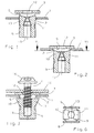
- the plastic nut is on average along the line I-I of Figure 4a shown, which is inserted into the component 1, which has the opening 2 for it.
- the plastic nut has the flange 3, which is in contact with the component 1 is determined when the plastic nut is fully inserted into component 1 is (see Figure 2).
- the flange 3 can be seen in FIGS. 4 and 5 Walls 5 and 6 or 7 and 8 connected to the nut piece 9, from which in The two snap hooks 10 and 11 grow out towards the flange 3, which are shown in their relaxed position as shown in FIG which they can be pushed through in the opening 2 of the component 1.
- Figure 3 shows the fully pushed through the opening 2 Screw 4, the two snap hooks when screwed into the nut piece 9 10 and 11 has pushed outwards, so with the flange 3 Apply facing surfaces to component 1.
- Figure 3 serves the plastic nut with the screw 4 screwed into it, on the Component 1 to attach the other component 14, which when tightening the Screw 4 is pressed from the head 15 to the flange 3.
- the nut piece 9 according to FIG. 3 still has the compared to FIGS. 1 and 2 Special feature that the screw hole 16 according to FIG. 3 is a Blind hole.
- FIGS. 5a and 5b is a modification compared to Figures 4a and 4b.
- Figures 5a and 5b namely the walls 7 and 8 with a weakening 18 in their central area provided, due to which the walls 7 and 8 inwards, ie towards snap on the snap hooks 10, 11, as shown in Figure 5b.
- the kink direction determined by the position of the weakening 17 or 18 is thereby to explain that in addition to the weakening, that is, in the corresponding thin part of the walls 5, 6 and 7, 8 a significant pressure concentration when Tightening the screw 4 results in the ones running in the material of the walls Print lines either to one side or to the other side of the Walls converge and concentrate there, with the pressure of each an oblique direction that corresponds to this pressure and thus a direction of buckling given is.
- 7a and 7b is a plastic nut in which the Walls 19, 20 each have two weakenings 21 and 22, of which the Attenuations 21 on the side facing away from the snap hooks 10, 11 and the Attenuations 22 are arranged on the side facing the snap hooks 10, 11 are.
- the result is a meandering shape Buckling of the walls 19 and 20, which creates a correspondingly large tolerance range can be bridged with this plastic nut.
Abstract
Description
Die Erfindung bezieht sich auf eine Kunststoffmutter zur Aufnahme an einem einen Durchbruch aufweisenden Bauteil, die mit einem ein Aufnahmeloch für eine Schraube dienenden Mutterstück in den Durchbruch einsteckbar ist und zur Anlage an der einen Seite des Bauteils mit einem Flansch und zur Anlage an der anderen Seite des Bauteils mit die Kunststoffmutter am Bauteil sichernden Schnapphaken versehen ist, die in entspannter Lage einerseits in ihrer radialen Ausdehnung dem Innenmaß des Durchbruchs entsprechen, andererseits das Aufnahmeloch überdecken und beim Einsetzen der Schraube ausspreizen und sich dem Bauteil gegenüberstellen. Eine derartige Kunststoffmutter ist in der deutschen Offenlegungsschrift DE 197 28 988 A1, Figuren 16a bis d, dargestellt und beschrieben.The invention relates to a plastic nut for receiving on a a breakthrough component that has a receiving hole for a screw serving nut piece can be inserted into the opening and for System on one side of the component with a flange and for system on the secure the other side of the component with the plastic nut on the component Snap hook is provided, the one hand in a relaxed position in its radial Expansion correspond to the internal dimension of the opening, on the other hand, the receiving hole cover and spread out when inserting the screw face the component. Such a plastic nut is in the German Publication DE 197 28 988 A1, Figures 16a to d, shown and described.
Der Erfindung liegt die Aufgabe zugrunde, die vorstehend erläuterte Kunststoffmutter so zu gestalten, dass durch Anziehen der in das Mutterstück eingedrehten Schraube die Kunststoffmutter beidseitig in Bezug auf das Bauteil derart fest zur Anlage gebracht wird, dass sich dabei der Abstand zwischen Flansch und Schnapphaken auf die Dicke des Bauteils verringert und damit die Kunststoffmutter an Bauteilen unterschiedlicher Dicke angebracht werden kann.The invention is based, the plastic nut explained above to be designed so that by tightening the screwed into the nut Screw the plastic nut so tight on both sides with respect to the component Is brought that the distance between the flange and Snap hooks reduced to the thickness of the component and thus the plastic nut can be attached to components of different thickness.
Die erfindungsgemäße Lösung besteht darin, dass neben den Schnapphaken in Ausspreizrichtung verlaufende Wände angeordnet sind, die sich vom Flansch zum Mutterstück erstrecken und eine in ihrem mittleren Bereich und in Ausspreizrichtung verlaufende derartige Schwächung ihrer Wandstärke besitzen, dass beim Anziehen der Schraube durch Knicken der Wände an der Schwächung sich der Flansch und die Schnapphaken beidseitig an dem Bauteil anlegen.The solution according to the invention is that in addition to the snap hook Spreading extending walls are arranged which extend from the flange to Extend nut piece and one in its central area and in the direction of expansion have such weakening of their wall thickness that at Tighten the screw by bending the walls to weaken the Place the flange and the snap hooks on both sides of the component.
Durch die ausknickbaren Wände ergibt sich beim Anziehen der Schraube eine Annäherung der Schnapphaken an das Bauteil, bis schließlich einerseits der Flansch an der einen Seite des Bauteils und die Schnapphaken an der anderen Seite des Bauteils anliegen, womit der Kunststoffmutter in Bezug auf das Bauteil eine definierte Lage gegeben wird. Dies ist insbesondere für den Fall wichtig, dass mit der Schraube an der Kunststoffmutter ein weiteres Bauelement anzubringen ist, das dann ebenfalls eine definierte Lage zu dem Bauteil besitzt und beibehält. Bei diesem Anziehen der Schraube ermöglicht das Knicken der Wände an deren Schwächung eine Anpassung der Kunststoffmutter an verschiedene Dicken eines beispielsweise durch eine Platte gegebenen Bauteils, wobei diese Knickung umso stärker ausfällt, je dünner das betreffende Bauteil ist. Dabei lässt sich durch die Knickung der Wände zusätzlich der Effekt erzielen, durch die bei der Knickung gewissermaßen zusammengefalteten Teile der Wände eine Ausrichtung der Lage des Mutterstücks in Bezug auf die Schnapphaken bzw. den Flansch zu bewirken, wodurch den geknickten Wänden eine zusätzliche Funktion zukommt.The foldable walls result in a tightening of the screw The snap hooks approach the component until finally the one Flange on one side of the component and the snap hooks on the other Side of the component, with the plastic nut in relation to the component a defined location is given. This is particularly important in the event that attach another component with the screw on the plastic nut is, which then also has a defined position to the component and maintains. Tightening the screw allows the walls to buckle Weakening an adjustment of the plastic nut to different thicknesses of a for example given by a plate component, this buckling all the more turns out stronger, the thinner the component in question. It can be done through the Kinking the walls also achieve the effect of kinking to some extent folded parts of the walls align the location the nut piece in relation to the snap hooks or the flange, which gives the kinked walls an additional function.
Einerseits kann man die Schwächung der Wände auf deren den Schnapphaken zugewandten Seite anordnen. In diesem Falle knicken die Wände nach außen aus, also von den Schnapphaken weg, wobei sich die Schwächung von den Schnapphaken entfernt. Die auswärts geknickten Wandteile geben dem die Schraube aufnehmenden Mutterstück bei deren Verdrehung einen zusätzlichen Widerstand, so dass die innere Stabilität der Kunststoffmutter, durch erschwerte Verdrehbarkeit des Mutterstücks gegenüber dem Flansch erheblich vergrößert wird.On the one hand you can see the weakening of the walls on their snap hooks Arrange the facing side. In this case the walls buckle outwards So away from the snap hooks, whereby the weakening of the snap hooks away. The wall parts bent outwards give the screw holder Nut piece when twisting an additional resistance, so that the internal stability of the plastic nut, due to difficult rotatability the nut piece is significantly enlarged compared to the flange.
Andererseits ist es auch möglich, die Schwächung der Wände so zu legen, dass diese auf deren den Schnapphaken abgewandten Seite angeordnet ist. In diesem Falle knicken die Wände nach innen aus, also in Richtung auf die Schnapphaken und legen sich an diese an, so dass bei dieser Gestaltung den Schnapphaken und dem Mutterstück eine Zentrierung gegenüber dem Flansch gegeben wird.On the other hand, it is also possible to set the weakening of the walls in such a way that this is arranged on the side facing away from the snap hook. In this Trap fold the walls inwards, i.e. towards the snap hooks and put on this so that with this design the snap hook and the nut piece is given a centering with respect to the flange.
Die Schwächung der Wände kann man jeweils einzeln als auch mehrfach in den Wänden vorsehen. Im letzteren Falle gestaltet man die Wände derart, dass die Wände jeweils mehrere Schwächungen aufweisen, die abwechselnd auf der den Schnapphaken zugewandten und abgewandten Seite angeordnet sind. Beim Anziehen der Schraube ergibt sich damit eine mäanderförmige Knickung in den Wänden, wodurch ein besonders großer Bereich der Unterschiedlichkeit des Abstands zwischen Flansch und Schnapphaken einerseits und Dicke des Bauteils andererseits überbrückt werden kann.The weakening of the walls can be done individually or several times in the Provide walls. In the latter case, the walls are designed in such a way that the Walls each have several weakenings, which alternately on the Snap hooks facing and facing away are arranged. While dressing the screw thus results in a meandering kink in the Walls, creating a particularly large range of difference in distance between flange and snap hook on the one hand and thickness of the component on the other hand can be bridged.
Das Mutterstück gestaltet man zweckmäßig so, dass das Aufnahmeloch für die Schraube im Bereich der Wände und im Bereich des Mutterstücks als Gewindeloch ausgebildet ist. Hierdurch lassen sich beim Einführen einer Schraube die beiden Schnapphaken entgegen ihrer Federspannung relativ leicht nach außen wegdrücken, bis dann die Schraube im Bereich des Mutterstücks auf das Gewindeloch auftrifft und sich in diesem Bereich sein Gewinde beim Weiterdrehen der Schraube ausfurcht.The mother piece is appropriately designed so that the receiving hole for the Screw in the area of the walls and in the area of the nut as a threaded hole is trained. This allows the two when inserting a screw Push the snap hook relatively slightly outwards against its spring tension, until then the screw in the area of the nut piece on the threaded hole strikes and in this area its thread when turning the screw further ausfurcht.
Das Gewindeloch kann dabei als beidseitig offenes Loch oder auch als Sackloch ausgebildet sein. Im letzteren Falle kann dies aus Gründen der Erzielung einer besonderen Abdichtung zweckmäßig sein.The threaded hole can be an open hole on both sides or a blind hole be trained. In the latter case, this can be done in order to achieve a special sealing may be appropriate.
In den Figuren sind Ausführungsbeispiele der Erfindung dargestellt. Es zeigen:
Figur 1- einen Schnitt durch die Kunststoffmutter, der durch die Schnapphaken in Axialrichtung der Kunststoffmutter verläuft, und zwar beim Einführen in den Durchbruch eines Bauteils;
Figur 2- die gleiche Kunststoffmutter in einer Position vollständig durch den Durchbruch hindurchgeführt;
Figur 3- die Kunststoffmutter in der Position gemäß
Figur 2 mit eingedrehter Schraube, wobei die Schnapphaken ausgespreizt sind, aber noch nicht an dem Bauteil anliegen. - Figur 4a
- die Kunststoffmutter gemäß
Figur 2 um 90° gedreht, wobei der Schnitt durch die Wände verläuft, an deren Innenseite die Schwächung angeordnet ist; - Figur 4b
- die Kunststoffmutter gemäß Figur 4a mit nach außen geknickten Wänden bei fest angezogener Schraube;
- Figur 5a
- eine Kunststoffmutter ähnlich derjenigen gemäß Figur 4a, jedoch mit an der Außenseite der Wände angeordneter Schwächung;
- Figur 5b
- die Kunststoffmutter gemäß Figur 5a mit nach innen eingeknickten Wänden bei angezogener Schraube;
Figur 6- einen Schnitt längs der Linie VI-VI aus
Figur 2; - Figur 7a
- eine Kunststoffmutter mit zwei aufeinanderfolgenden Schwächungen in jeder Wand, die abwechselnd auf der den Schnapphaken zugewandten und abgewandten Seite liegen;
- Figur 7b
- die Kunststoffmutter gemäß Figur 7a mit nach innen und außen mäanderförmig abgeknickten Wänden bei angezogener Schraube.
- Figure 1
- a section through the plastic nut, which runs through the snap hooks in the axial direction of the plastic nut, namely when inserted into the opening of a component;
- Figure 2
- the same plastic nut is fully inserted through the opening in one position;
- Figure 3
- the plastic nut in the position according to FIG. 2 with the screw turned in, the snap hooks being spread out but not yet in contact with the component.
- Figure 4a
- the plastic nut according to Figure 2 rotated by 90 °, the section running through the walls, on the inside of which the weakening is arranged;
- Figure 4b
- the plastic nut according to Figure 4a with walls bent outwards when the screw is tightened;
- Figure 5a
- a plastic nut similar to that according to Figure 4a, but with a weakening arranged on the outside of the walls;
- Figure 5b
- the plastic nut according to Figure 5a with walls bent inwards when the screw is tightened;
- Figure 6
- a section along the line VI-VI of Figure 2;
- Figure 7a
- a plastic nut with two consecutive weakenings in each wall, alternately on the side facing the snap hooks and facing away;
- Figure 7b
- the plastic nut according to Figure 7a with meandering walls bent inwards and outwards when the screw is tightened.
In der Figur 1 ist die Kunststoffmutter im Schnitt längs der Linie I-I aus Figur 4a
dargestellt, die in das Bauteil 1 eingesetzt ist, das dafür den Durchbruch 2 aufweist.
Die Kunststoffmutter besitzt den Flansch 3, der zur Anlage an dem Bauteil
1 bestimmt ist, wenn die Kunststoffmutter vollständig in das Bauteil 1 eingesetzt
ist (siehe Figur 2). Der Flansch 3 ist über die aus den Figuren 4 und 5 ersichtlichen
Wände 5 und 6 bzw. 7 und 8 mit dem Mutterstück 9 verbunden, aus dem in
Richtung auf den Flansch 3 die beiden Schnapphaken 10 und 11 herauswachsen,
die gemäß der Darstellung in Figur 1 in ihrer entspannten Lage gezeigt sind, in
der sie in dem Durchbruch 2 des Bauteils 1 hindurchgeschoben werden können.
Wegen der einander nach innen zugewandten Lage der Schnapphaken 10 und 11
behindern diese dabei das Hindurchführen der Kunststoffmutter durch den Durchbruch
2 nicht, so dass bei vollständigem Hindurchführen der Kunststoffmutter
diese die in der Figur 2 dargestellte Lage erreicht, in der der Flansch 3 zur Anlage
an dem Bauteil 1 kommt. Die Kunststoffmutter weist zur Aufnahme einer Schraube
4 (siehe Figur 3) auf der Seite des Flansches 3 das Durchgangsloch 12 und auf
der Seite des Mutterstücks 9 das Gewindeloch 13 auf. Eine einzudrehende
Schraube 4 lässt sich gemäß Figur 3 mit ihrem Gewindeteil durch das Durchgangsloch
12 hindurchschieben, bis der Gewindeanfang auf das Gewindeloch 13
trifft, von wo aus dann die Schraube 4 vorzugsweise unter Furchen eines Gewindes
eingedreht werden kann.In Figure 1, the plastic nut is on average along the line I-I of Figure 4a
shown, which is inserted into the
Figur 3 zeigt die durch den Durchbruch 2 vollständig hindurchgeschobene
Schraube 4, die bei ihrem Eindrehen in das Mutterstück 9 die beiden Schnapphaken
10 und 11 nach außen weggedrückt hat, die sich so mit ihren dem Flansch 3
zugewandten Flächen an das Bauteil 1 anlegen. Gemäß der Darstellung in Figur 3
dient die Kunststoffmutter mit der in sie eingedrehten Schraube 4 dazu, an dem
Bauteil 1 das weitere Bauelement 14 zu befestigen, das beim Anziehen der
Schraube 4 von deren Kopf 15 an den Flansch 3 angedrückt wird.Figure 3 shows the fully pushed through the
Das Mutterstück 9 gemäß Figur 3 weist gegenüber den Figuren 1 und 2 noch die
Besonderheit auf, dass es sich bei dem Schraubenloch 16 gemäß Figur 3 um ein
Sackloch handelt. The
Wie in den Figuren 4a und b dargestellt, werden bei dem vorstehend beschriebenen
Anziehen der Schraube 4 die beiden Wände 5 und 6 geknickt, und zwar wegen
ihrer in ihrem mittleren Bereich und auf der den Schnapphaken 10, 11 zugewandten
Seite angeordneten Schwächung 17 (siehe Figur 4a) nach außen hin, wie
es in der Figur 4b dargestellt ist. Aufgrund dieser Gestaltung der Kunststoffmutter
hat diese beim Anziehen der Schraube 4 einen Toleranzbereich überschritten, der
durch die Knickung der Wände 5 und 6 bestimmt ist und der sich deutlich aus
einem Vergleich der Figuren 4a und 4b ergibt. Dieser Toleranzbereich entspricht
dem Unterschied zwischen dem Abstand von Flansch 3 zu den Schnapphaken 10
und 11 gegenüber der Dicke des Bauteils 1.As shown in Figures 4a and b, the above described
Tightening the
Bei der Darstellung gemäß den Figuren 5a und 5b handelt es sich um eine Abwandlung
gegenüber den Figuren 4a und 4b. Gemäß den Figuren 5a und 5b sind
nämlich die Wände 7 und 8 mit einer Schwächung 18 in ihrem mittleren Bereich
versehen, aufgrund deren dessen die Wände 7 und 8 nach innen, also in Richtung
auf die Schnapphaken 10, 11 knicken, wie dies in Figur 5b dargestellt ist.The illustration according to FIGS. 5a and 5b is a modification
compared to Figures 4a and 4b. According to Figures 5a and 5b
namely the
Die durch die Lage der Schwächung 17 bzw. 18 bestimmte Knickrichtung ist dadurch
zu erklären, dass sich neben der Schwächung, also in dem entsprechend
dünnen Teil der Wände 5, 6 bzw. 7, 8 eine erhebliche Druckkonzentration beim
Anziehen der Schraube 4 ergibt, so dass die in dem Material der Wände verlaufenden
Drucklinien entweder nach der einen Seite oder nach der anderen Seite der
Wände zusammenlaufen und sich dort konzentrieren, womit dem Druck jeweils
eine entsprechend diesem Druck verlaufende Schrägrichtung und damit Knickrichtung
gegeben ist.The kink direction determined by the position of the weakening 17 or 18 is thereby
to explain that in addition to the weakening, that is, in the corresponding
thin part of the
Bei den Figuren 7a und 7b handelt es sich um eine Kunststoffmutter, bei der die
Wände 19, 20 jeweils zwei Schwächungen 21 und 22 aufweisen, von denen die
Schwächungen 21 auf der den Schnapphaken 10, 11 abgewandten Seite und die
Schwächungen 22 auf der den Schnapphaken 10, 11 zugewandten Seite angeordnet
sind. Bei Eindrehen der Schraube 4 ergibt sich daher eine mäanderförmige
Knickung der Wände 19 und 20, wodurch ein entsprechend großer Toleranzbereich
mit dieser Kunststoffmutter überbrückt werden kann.7a and 7b is a plastic nut in which the
Claims (6)
Applications Claiming Priority (2)
| Application Number | Priority Date | Filing Date | Title |
|---|---|---|---|
| DE10305610 | 2003-02-11 | ||
| DE10305610A DE10305610A1 (en) | 2003-02-11 | 2003-02-11 | Plastic nut for mounting on a component with a breakthrough |
Publications (2)
| Publication Number | Publication Date |
|---|---|
| EP1447576A1 true EP1447576A1 (en) | 2004-08-18 |
| EP1447576B1 EP1447576B1 (en) | 2005-10-26 |
Family
ID=32668018
Family Applications (1)
| Application Number | Title | Priority Date | Filing Date |
|---|---|---|---|
| EP04002892A Expired - Lifetime EP1447576B1 (en) | 2003-02-11 | 2004-02-10 | Plastic nut for a construction unit exhibiting a break-through |
Country Status (9)
| Country | Link |
|---|---|
| US (1) | US7014405B2 (en) |
| EP (1) | EP1447576B1 (en) |
| JP (1) | JP2004245415A (en) |
| KR (1) | KR20040073358A (en) |
| CN (1) | CN1521412A (en) |
| AT (1) | ATE307985T1 (en) |
| BR (1) | BRPI0400177A (en) |
| DE (2) | DE10305610A1 (en) |
| ES (1) | ES2247567T3 (en) |
Cited By (4)
| Publication number | Priority date | Publication date | Assignee | Title |
|---|---|---|---|---|
| EP1767793A2 (en) * | 2005-09-23 | 2007-03-28 | HILTI Aktiengesellschaft | Mounting device for the attachment of solar panels with an assembly rail |
| EP1918596A1 (en) * | 2006-11-03 | 2008-05-07 | Herbert Schruff | Blind rivet and use thereof |
| EP2960531A1 (en) * | 2014-06-27 | 2015-12-30 | Bollhoff Otalu S.A. | Crimping piece on a support, device comprising such a piece and methods of manufacturing such a part and such a device |
| WO2017034875A1 (en) * | 2015-08-27 | 2017-03-02 | Alcoa Inc. | Fastener locking members |
Families Citing this family (19)
| Publication number | Priority date | Publication date | Assignee | Title |
|---|---|---|---|---|
| DE10235799A1 (en) * | 2002-08-05 | 2004-03-04 | Ejot Gmbh & Co. Kg | Plastic nut for attachment to a component |
| EP1746293A1 (en) * | 2005-07-20 | 2007-01-24 | Joseph Talpe | Fixing device for hollow frames and plate surfaces |
| WO2007074352A1 (en) * | 2005-12-29 | 2007-07-05 | Infineon Technologies Ag | Electronic component and a method of fabricating an electronic component |
| CA2540628A1 (en) * | 2006-01-17 | 2007-07-17 | Cobra Fixations Cie Ltee - Cobra Anchors Co. Ltd. | Plastic anchor for drywall, plaster, brick, concrete, etc. |
| DE202006002173U1 (en) | 2006-02-10 | 2007-06-21 | Ejot Gmbh & Co. Kg | In a breakthrough of a metal plate usable mother part |
| GB2449291B (en) * | 2007-05-17 | 2013-01-23 | Legrand Electric Ltd | Technique for securing components together |
| CA2697092C (en) * | 2007-07-20 | 2016-06-14 | Henkel Ag & Co. Kgaa | Molded polymeric spacing devices |
| EP2216554B1 (en) * | 2009-02-06 | 2012-04-18 | Fairchild Fasteners Europe - Camloc GmbH | Disposable casing |
| DE102010023992A1 (en) * | 2010-06-16 | 2011-12-22 | Volkswagen Ag | Arrangement for fastening plastic bumper at supporting component of vehicle body of motor car, has screw bolt comprising thread outer dimension, which is larger than dimension of hole at plastic bumper |
| EP2551531B1 (en) * | 2011-07-25 | 2017-03-22 | Faurecia Interieur Industrie | Attachment device for fixing on a plate having a hole and assembly comprising such an attachment device |
| DE102013202723B4 (en) | 2013-02-20 | 2023-04-20 | Bayerische Motoren Werke Aktiengesellschaft | mounting assembly |
| KR20170040544A (en) * | 2015-10-05 | 2017-04-13 | 삼성전자주식회사 | Inner case for refrigerator and manufacturing method of the same |
| CN107509353A (en) * | 2016-06-14 | 2017-12-22 | 伊姆西公司 | Bar and the fixing device that is used cooperatively with frame for frame |
| CN109952441B (en) * | 2016-08-12 | 2022-09-30 | 伊利诺斯工具制品有限公司 | Rivet fastener assembly |
| DE102017107162A1 (en) | 2017-04-04 | 2018-10-04 | Eberspächer Exhaust Technology GmbH & Co. KG | mounting assembly |
| US10927876B1 (en) * | 2017-11-02 | 2021-02-23 | Robert Rosebrugh | Rivet nut fastener |
| CN110465737B (en) | 2018-05-09 | 2023-11-21 | 杨百翰大学 | System and method for friction bit engagement |
| US11268557B2 (en) | 2018-10-10 | 2022-03-08 | Illinois Tool Works Inc. | Rivet fastener assembly and method of use thereof |
| CN109630936A (en) * | 2018-12-29 | 2019-04-16 | 贵派电器股份有限公司 | A kind of anti-vibration lamp |
Citations (2)
| Publication number | Priority date | Publication date | Assignee | Title |
|---|---|---|---|---|
| US3343441A (en) * | 1965-04-01 | 1967-09-26 | United Carr Inc | Self-securing fastener |
| DE19728988A1 (en) * | 1997-07-07 | 1999-01-14 | Ejot Verbindungstech Gmbh & Co | Plastic nut joining plates together |
Family Cites Families (9)
| Publication number | Priority date | Publication date | Assignee | Title |
|---|---|---|---|---|
| US3313083A (en) * | 1963-05-29 | 1967-04-11 | Tinnerman Products Inc | Deformable plastic fastener |
| JPS5514359A (en) * | 1978-07-18 | 1980-01-31 | Nifco Inc | Panel fitting instrument |
| ES255417Y (en) | 1979-01-25 | 1982-10-16 | PERFECTED FASTENING DEVICE. | |
| US4312612A (en) * | 1979-05-31 | 1982-01-26 | United Packages Limited | Screw fixing device |
| US5078561A (en) * | 1990-11-08 | 1992-01-07 | Illinois Tools Works, Inc. | Plastic expansion nut |
| US5690454A (en) * | 1992-11-23 | 1997-11-25 | Dry Dock Industries, Inc. | Anchoring retainer for threaded fasteners |
| JP2599730Y2 (en) * | 1993-08-02 | 1999-09-20 | ポップリベット・ファスナー株式会社 | Carpet clips |
| DE59701255D1 (en) | 1996-09-25 | 2000-04-20 | Ejot Verbindungstech Gmbh & Co | PLASTIC NUT FOR CONNECTING PANEL-LIKE PARTS |
| JP2000329121A (en) * | 1999-05-19 | 2000-11-28 | Nippon Pop Rivets & Fasteners Ltd | Screw grommet |
-
2003
- 2003-02-11 DE DE10305610A patent/DE10305610A1/en not_active Withdrawn
-
2004
- 2004-02-04 BR BR0400177-0A patent/BRPI0400177A/en not_active Application Discontinuation
- 2004-02-10 CN CNA2004100053039A patent/CN1521412A/en active Pending
- 2004-02-10 DE DE502004000111T patent/DE502004000111D1/en not_active Expired - Lifetime
- 2004-02-10 ES ES04002892T patent/ES2247567T3/en not_active Expired - Lifetime
- 2004-02-10 JP JP2004033227A patent/JP2004245415A/en active Pending
- 2004-02-10 AT AT04002892T patent/ATE307985T1/en not_active IP Right Cessation
- 2004-02-10 EP EP04002892A patent/EP1447576B1/en not_active Expired - Lifetime
- 2004-02-11 KR KR1020040009075A patent/KR20040073358A/en not_active Application Discontinuation
- 2004-02-11 US US10/775,105 patent/US7014405B2/en not_active Expired - Lifetime
Patent Citations (2)
| Publication number | Priority date | Publication date | Assignee | Title |
|---|---|---|---|---|
| US3343441A (en) * | 1965-04-01 | 1967-09-26 | United Carr Inc | Self-securing fastener |
| DE19728988A1 (en) * | 1997-07-07 | 1999-01-14 | Ejot Verbindungstech Gmbh & Co | Plastic nut joining plates together |
Cited By (12)
| Publication number | Priority date | Publication date | Assignee | Title |
|---|---|---|---|---|
| EP1767793A2 (en) * | 2005-09-23 | 2007-03-28 | HILTI Aktiengesellschaft | Mounting device for the attachment of solar panels with an assembly rail |
| EP1767793A3 (en) * | 2005-09-23 | 2012-09-19 | HILTI Aktiengesellschaft | Mounting device for the attachment of solar panels with an assembly rail |
| EP1918596A1 (en) * | 2006-11-03 | 2008-05-07 | Herbert Schruff | Blind rivet and use thereof |
| US7901171B2 (en) | 2006-11-03 | 2011-03-08 | Herbert Schruff | Blind fastener and method |
| EP2960531A1 (en) * | 2014-06-27 | 2015-12-30 | Bollhoff Otalu S.A. | Crimping piece on a support, device comprising such a piece and methods of manufacturing such a part and such a device |
| FR3022962A1 (en) * | 2014-06-27 | 2016-01-01 | Bollhoff Otalu Sa | CRIMPING PIECE ON A SUPPORT, DEVICE COMPRISING SUCH A PART AND METHODS OF MANUFACTURING SUCH A PART AND SUCH A DEVICE |
| FR3049665A1 (en) * | 2014-06-27 | 2017-10-06 | Bollhoff Otalu Sa | CRIMPING PIECE ON A SUPPORT, DEVICE COMPRISING SUCH A PART AND METHODS OF MANUFACTURING SUCH A PART AND SUCH A DEVICE |
| US9903402B2 (en) | 2014-06-27 | 2018-02-27 | Bollhoff Otalu S.A. | Piece to be crimped on a support, device comprising such a piece and methods for manufacturing such a piece and such a device |
| WO2017034875A1 (en) * | 2015-08-27 | 2017-03-02 | Alcoa Inc. | Fastener locking members |
| CN106481635A (en) * | 2015-08-27 | 2017-03-08 | 美铝公司 | Securing member locking component |
| US10215218B2 (en) | 2015-08-27 | 2019-02-26 | Arconic Inc. | Fastener locking members |
| US10683887B2 (en) | 2015-08-27 | 2020-06-16 | Arconic Inc. | Fastener locking members |
Also Published As
| Publication number | Publication date |
|---|---|
| EP1447576B1 (en) | 2005-10-26 |
| US7014405B2 (en) | 2006-03-21 |
| KR20040073358A (en) | 2004-08-19 |
| DE10305610A1 (en) | 2004-08-19 |
| JP2004245415A (en) | 2004-09-02 |
| BRPI0400177A (en) | 2004-12-28 |
| CN1521412A (en) | 2004-08-18 |
| ES2247567T3 (en) | 2006-03-01 |
| DE502004000111D1 (en) | 2005-12-01 |
| US20040156694A1 (en) | 2004-08-12 |
| ATE307985T1 (en) | 2005-11-15 |
Similar Documents
| Publication | Publication Date | Title |
|---|---|---|
| EP1447576B1 (en) | Plastic nut for a construction unit exhibiting a break-through | |
| DE808510C (en) | Insert body for screwing into components and for receiving a machine screw | |
| DE10357844B4 (en) | fastening system | |
| EP1767719A2 (en) | Fixing device for fastening solar panels to a C-shaped mounting rail | |
| DE10034968B4 (en) | mounting clip | |
| EP3478975B1 (en) | Clip with a head and a shank extending from the head along a longitudinal axis | |
| DE4444467C2 (en) | Self-tapping screw | |
| WO2009097842A1 (en) | Plug-in device | |
| DE102009024264A1 (en) | Fastener i.e. nut, for screwing-on threaded bolt, has borehole with attachment areas, which exhibit inner diameters adapted to different standard thread diameters of threaded bolt, respectively | |
| DE102012208482A1 (en) | fastening device | |
| DE102006005784A1 (en) | Medical syringe with a dual purpose finger support that is configured to also act as a quality assurance marking, with its removal causing damage to the syringe body and or the finger support | |
| DE102008036386B4 (en) | Pipe clamp and profile element for a pipe clamp | |
| DE20312075U1 (en) | Device with two hollow profiles held together by a connecting screw and tool for this | |
| EP1039043B1 (en) | Sanitary fitting with a nut for its fixing | |
| DE202008007378U1 (en) | screw clip | |
| EP1195548B1 (en) | Pipe clamp | |
| DE102006052379A1 (en) | Screw for tightening cable and pipe, has screw head which is formed by cap, divided into screw head section and target breaking section by circular groove, where screw head section is connected with shaft by fastening unit | |
| DE60007247T2 (en) | Bracket with screw fastening for conveyor belt | |
| EP3372916B1 (en) | System for reversibly attaching an element of air conditioning and ventilation assembly | |
| DE202010009496U1 (en) | Captive held screw | |
| DE102018122701A1 (en) | Holder system for attaching a container to a vehicle | |
| DE10304514A1 (en) | Fixing part for a hose clamp | |
| DE2905753C2 (en) | ||
| DE102014104597A1 (en) | fastener | |
| DE4021245A1 (en) | TURN-IN AND / OR FOLD-IN FASTENER FOR FIXING PROFILE PARTS |
Legal Events
| Date | Code | Title | Description |
|---|---|---|---|
| PUAI | Public reference made under article 153(3) epc to a published international application that has entered the european phase |
Free format text: ORIGINAL CODE: 0009012 |
|
| AK | Designated contracting states |
Kind code of ref document: A1 Designated state(s): AT BE BG CH CY CZ DE DK EE ES FI FR GB GR HU IE IT LI LU MC NL PT RO SE SI SK TR |
|
| AX | Request for extension of the european patent |
Extension state: AL LT LV MK |
|
| 17P | Request for examination filed |
Effective date: 20040730 |
|
| 17Q | First examination report despatched |
Effective date: 20040915 |
|
| GRAP | Despatch of communication of intention to grant a patent |
Free format text: ORIGINAL CODE: EPIDOSNIGR1 |
|
| AKX | Designation fees paid |
Designated state(s): AT BE BG CH CY CZ DE DK EE ES FI FR GB GR HU IE IT LI LU MC NL PT RO SE SI SK TR |
|
| GRAS | Grant fee paid |
Free format text: ORIGINAL CODE: EPIDOSNIGR3 |
|
| GRAA | (expected) grant |
Free format text: ORIGINAL CODE: 0009210 |
|
| AK | Designated contracting states |
Kind code of ref document: B1 Designated state(s): AT BE BG CH CY CZ DE DK EE ES FI FR GB GR HU IE IT LI LU MC NL PT RO SE SI SK TR |
|
| PG25 | Lapsed in a contracting state [announced via postgrant information from national office to epo] |
Ref country code: CZ Free format text: LAPSE BECAUSE OF FAILURE TO SUBMIT A TRANSLATION OF THE DESCRIPTION OR TO PAY THE FEE WITHIN THE PRESCRIBED TIME-LIMIT Effective date: 20051026 Ref country code: FI Free format text: LAPSE BECAUSE OF FAILURE TO SUBMIT A TRANSLATION OF THE DESCRIPTION OR TO PAY THE FEE WITHIN THE PRESCRIBED TIME-LIMIT Effective date: 20051026 Ref country code: IE Free format text: LAPSE BECAUSE OF FAILURE TO SUBMIT A TRANSLATION OF THE DESCRIPTION OR TO PAY THE FEE WITHIN THE PRESCRIBED TIME-LIMIT Effective date: 20051026 Ref country code: SI Free format text: LAPSE BECAUSE OF FAILURE TO SUBMIT A TRANSLATION OF THE DESCRIPTION OR TO PAY THE FEE WITHIN THE PRESCRIBED TIME-LIMIT Effective date: 20051026 Ref country code: SK Free format text: LAPSE BECAUSE OF FAILURE TO SUBMIT A TRANSLATION OF THE DESCRIPTION OR TO PAY THE FEE WITHIN THE PRESCRIBED TIME-LIMIT Effective date: 20051026 Ref country code: RO Free format text: LAPSE BECAUSE OF FAILURE TO SUBMIT A TRANSLATION OF THE DESCRIPTION OR TO PAY THE FEE WITHIN THE PRESCRIBED TIME-LIMIT Effective date: 20051026 Ref country code: NL Free format text: LAPSE BECAUSE OF FAILURE TO SUBMIT A TRANSLATION OF THE DESCRIPTION OR TO PAY THE FEE WITHIN THE PRESCRIBED TIME-LIMIT Effective date: 20051026 |
|
| REG | Reference to a national code |
Ref country code: GB Ref legal event code: FG4D Free format text: NOT ENGLISH |
|
| REG | Reference to a national code |
Ref country code: CH Ref legal event code: EP Ref country code: CH Ref legal event code: NV Representative=s name: A. BRAUN, BRAUN, HERITIER, ESCHMANN AG PATENTANWAE |
|
| GBT | Gb: translation of ep patent filed (gb section 77(6)(a)/1977) |
Effective date: 20051026 |
|
| REG | Reference to a national code |
Ref country code: IE Ref legal event code: FG4D Free format text: LANGUAGE OF EP DOCUMENT: GERMAN |
|
| REF | Corresponds to: |
Ref document number: 502004000111 Country of ref document: DE Date of ref document: 20051201 Kind code of ref document: P |
|
| PG25 | Lapsed in a contracting state [announced via postgrant information from national office to epo] |
Ref country code: GR Free format text: LAPSE BECAUSE OF FAILURE TO SUBMIT A TRANSLATION OF THE DESCRIPTION OR TO PAY THE FEE WITHIN THE PRESCRIBED TIME-LIMIT Effective date: 20060126 Ref country code: SE Free format text: LAPSE BECAUSE OF FAILURE TO SUBMIT A TRANSLATION OF THE DESCRIPTION OR TO PAY THE FEE WITHIN THE PRESCRIBED TIME-LIMIT Effective date: 20060126 Ref country code: BG Free format text: LAPSE BECAUSE OF FAILURE TO SUBMIT A TRANSLATION OF THE DESCRIPTION OR TO PAY THE FEE WITHIN THE PRESCRIBED TIME-LIMIT Effective date: 20060126 Ref country code: DK Free format text: LAPSE BECAUSE OF FAILURE TO SUBMIT A TRANSLATION OF THE DESCRIPTION OR TO PAY THE FEE WITHIN THE PRESCRIBED TIME-LIMIT Effective date: 20060126 |
|
| PG25 | Lapsed in a contracting state [announced via postgrant information from national office to epo] |
Ref country code: AT Free format text: LAPSE BECAUSE OF NON-PAYMENT OF DUE FEES Effective date: 20060210 |
|
| PG25 | Lapsed in a contracting state [announced via postgrant information from national office to epo] |
Ref country code: MC Free format text: LAPSE BECAUSE OF NON-PAYMENT OF DUE FEES Effective date: 20060228 Ref country code: LU Free format text: LAPSE BECAUSE OF NON-PAYMENT OF DUE FEES Effective date: 20060228 Ref country code: BE Free format text: LAPSE BECAUSE OF NON-PAYMENT OF DUE FEES Effective date: 20060228 |
|
| REG | Reference to a national code |
Ref country code: ES Ref legal event code: FG2A Ref document number: 2247567 Country of ref document: ES Kind code of ref document: T3 |
|
| PG25 | Lapsed in a contracting state [announced via postgrant information from national office to epo] |
Ref country code: PT Free format text: LAPSE BECAUSE OF FAILURE TO SUBMIT A TRANSLATION OF THE DESCRIPTION OR TO PAY THE FEE WITHIN THE PRESCRIBED TIME-LIMIT Effective date: 20060327 |
|
| NLV1 | Nl: lapsed or annulled due to failure to fulfill the requirements of art. 29p and 29m of the patents act | ||
| PG25 | Lapsed in a contracting state [announced via postgrant information from national office to epo] |
Ref country code: HU Free format text: LAPSE BECAUSE OF FAILURE TO SUBMIT A TRANSLATION OF THE DESCRIPTION OR TO PAY THE FEE WITHIN THE PRESCRIBED TIME-LIMIT Effective date: 20060427 |
|
| REG | Reference to a national code |
Ref country code: IE Ref legal event code: FD4D |
|
| ET | Fr: translation filed | ||
| PLBE | No opposition filed within time limit |
Free format text: ORIGINAL CODE: 0009261 |
|
| STAA | Information on the status of an ep patent application or granted ep patent |
Free format text: STATUS: NO OPPOSITION FILED WITHIN TIME LIMIT |
|
| 26N | No opposition filed |
Effective date: 20060727 |
|
| BERE | Be: lapsed |
Owner name: EJOT G.M.B.H. & CO. KG Effective date: 20060228 |
|
| PGFP | Annual fee paid to national office [announced via postgrant information from national office to epo] |
Ref country code: CH Payment date: 20080129 Year of fee payment: 5 |
|
| PGFP | Annual fee paid to national office [announced via postgrant information from national office to epo] |
Ref country code: IT Payment date: 20080227 Year of fee payment: 5 |
|
| REG | Reference to a national code |
Ref country code: CH Ref legal event code: PFA Owner name: EJOT GMBH & CO. KG Free format text: EJOT GMBH & CO. KG#UNTERE BIENHECKE#57334 BAD LAASPHE (DE) -TRANSFER TO- EJOT GMBH & CO. KG#UNTERE BIENHECKE#57334 BAD LAASPHE (DE) |
|
| PG25 | Lapsed in a contracting state [announced via postgrant information from national office to epo] |
Ref country code: EE Free format text: LAPSE BECAUSE OF FAILURE TO SUBMIT A TRANSLATION OF THE DESCRIPTION OR TO PAY THE FEE WITHIN THE PRESCRIBED TIME-LIMIT Effective date: 20051026 |
|
| PG25 | Lapsed in a contracting state [announced via postgrant information from national office to epo] |
Ref country code: CY Free format text: LAPSE BECAUSE OF FAILURE TO SUBMIT A TRANSLATION OF THE DESCRIPTION OR TO PAY THE FEE WITHIN THE PRESCRIBED TIME-LIMIT Effective date: 20051026 |
|
| PGFP | Annual fee paid to national office [announced via postgrant information from national office to epo] |
Ref country code: ES Payment date: 20090317 Year of fee payment: 6 |
|
| PGFP | Annual fee paid to national office [announced via postgrant information from national office to epo] |
Ref country code: GB Payment date: 20090204 Year of fee payment: 6 |
|
| REG | Reference to a national code |
Ref country code: CH Ref legal event code: PL |
|
| PG25 | Lapsed in a contracting state [announced via postgrant information from national office to epo] |
Ref country code: LI Free format text: LAPSE BECAUSE OF NON-PAYMENT OF DUE FEES Effective date: 20090228 Ref country code: CH Free format text: LAPSE BECAUSE OF NON-PAYMENT OF DUE FEES Effective date: 20090228 |
|
| PGFP | Annual fee paid to national office [announced via postgrant information from national office to epo] |
Ref country code: TR Payment date: 20100204 Year of fee payment: 7 |
|
| GBPC | Gb: european patent ceased through non-payment of renewal fee |
Effective date: 20100210 |
|
| REG | Reference to a national code |
Ref country code: ES Ref legal event code: FD2A Effective date: 20110329 |
|
| PG25 | Lapsed in a contracting state [announced via postgrant information from national office to epo] |
Ref country code: GB Free format text: LAPSE BECAUSE OF NON-PAYMENT OF DUE FEES Effective date: 20100210 Ref country code: IT Free format text: LAPSE BECAUSE OF NON-PAYMENT OF DUE FEES Effective date: 20090210 |
|
| PG25 | Lapsed in a contracting state [announced via postgrant information from national office to epo] |
Ref country code: ES Free format text: LAPSE BECAUSE OF NON-PAYMENT OF DUE FEES Effective date: 20110316 |
|
| PG25 | Lapsed in a contracting state [announced via postgrant information from national office to epo] |
Ref country code: ES Free format text: LAPSE BECAUSE OF NON-PAYMENT OF DUE FEES Effective date: 20100211 |
|
| PG25 | Lapsed in a contracting state [announced via postgrant information from national office to epo] |
Ref country code: TR Free format text: LAPSE BECAUSE OF NON-PAYMENT OF DUE FEES Effective date: 20110210 |
|
| PGFP | Annual fee paid to national office [announced via postgrant information from national office to epo] |
Ref country code: FR Payment date: 20140227 Year of fee payment: 11 |
|
| REG | Reference to a national code |
Ref country code: FR Ref legal event code: ST Effective date: 20151030 |
|
| PG25 | Lapsed in a contracting state [announced via postgrant information from national office to epo] |
Ref country code: FR Free format text: LAPSE BECAUSE OF NON-PAYMENT OF DUE FEES Effective date: 20150302 |
|
| PGFP | Annual fee paid to national office [announced via postgrant information from national office to epo] |
Ref country code: DE Payment date: 20180227 Year of fee payment: 15 |
|
| REG | Reference to a national code |
Ref country code: DE Ref legal event code: R119 Ref document number: 502004000111 Country of ref document: DE |
|
| PG25 | Lapsed in a contracting state [announced via postgrant information from national office to epo] |
Ref country code: DE Free format text: LAPSE BECAUSE OF NON-PAYMENT OF DUE FEES Effective date: 20190903 |