EP1448037A2 - Power module and method for producing the same - Google Patents
Power module and method for producing the same Download PDFInfo
- Publication number
- EP1448037A2 EP1448037A2 EP03026187A EP03026187A EP1448037A2 EP 1448037 A2 EP1448037 A2 EP 1448037A2 EP 03026187 A EP03026187 A EP 03026187A EP 03026187 A EP03026187 A EP 03026187A EP 1448037 A2 EP1448037 A2 EP 1448037A2
- Authority
- EP
- European Patent Office
- Prior art keywords
- terminal
- resin
- external connection
- connector
- waterproof
- Prior art date
- Legal status (The legal status is an assumption and is not a legal conclusion. Google has not performed a legal analysis and makes no representation as to the accuracy of the status listed.)
- Withdrawn
Links
Images


Classifications
-
- B—PERFORMING OPERATIONS; TRANSPORTING
- B60—VEHICLES IN GENERAL
- B60R—VEHICLES, VEHICLE FITTINGS, OR VEHICLE PARTS, NOT OTHERWISE PROVIDED FOR
- B60R16/00—Electric or fluid circuits specially adapted for vehicles and not otherwise provided for; Arrangement of elements of electric or fluid circuits specially adapted for vehicles and not otherwise provided for
- B60R16/02—Electric or fluid circuits specially adapted for vehicles and not otherwise provided for; Arrangement of elements of electric or fluid circuits specially adapted for vehicles and not otherwise provided for electric constitutive elements
- B60R16/023—Electric or fluid circuits specially adapted for vehicles and not otherwise provided for; Arrangement of elements of electric or fluid circuits specially adapted for vehicles and not otherwise provided for electric constitutive elements for transmission of signals between vehicle parts or subsystems
- B60R16/0238—Electrical distribution centers
-
- H—ELECTRICITY
- H05—ELECTRIC TECHNIQUES NOT OTHERWISE PROVIDED FOR
- H05K—PRINTED CIRCUITS; CASINGS OR CONSTRUCTIONAL DETAILS OF ELECTRIC APPARATUS; MANUFACTURE OF ASSEMBLAGES OF ELECTRICAL COMPONENTS
- H05K3/00—Apparatus or processes for manufacturing printed circuits
- H05K3/22—Secondary treatment of printed circuits
- H05K3/28—Applying non-metallic protective coatings
- H05K3/284—Applying non-metallic protective coatings for encapsulating mounted components
-
- H—ELECTRICITY
- H05—ELECTRIC TECHNIQUES NOT OTHERWISE PROVIDED FOR
- H05K—PRINTED CIRCUITS; CASINGS OR CONSTRUCTIONAL DETAILS OF ELECTRIC APPARATUS; MANUFACTURE OF ASSEMBLAGES OF ELECTRICAL COMPONENTS
- H05K7/00—Constructional details common to different types of electric apparatus
- H05K7/02—Arrangements of circuit components or wiring on supporting structure
- H05K7/026—Multiple connections subassemblies
-
- H—ELECTRICITY
- H05—ELECTRIC TECHNIQUES NOT OTHERWISE PROVIDED FOR
- H05K—PRINTED CIRCUITS; CASINGS OR CONSTRUCTIONAL DETAILS OF ELECTRIC APPARATUS; MANUFACTURE OF ASSEMBLAGES OF ELECTRICAL COMPONENTS
- H05K2201/00—Indexing scheme relating to printed circuits covered by H05K1/00
- H05K2201/03—Conductive materials
- H05K2201/0332—Structure of the conductor
- H05K2201/0388—Other aspects of conductors
- H05K2201/0397—Tab
-
- H—ELECTRICITY
- H05—ELECTRIC TECHNIQUES NOT OTHERWISE PROVIDED FOR
- H05K—PRINTED CIRCUITS; CASINGS OR CONSTRUCTIONAL DETAILS OF ELECTRIC APPARATUS; MANUFACTURE OF ASSEMBLAGES OF ELECTRICAL COMPONENTS
- H05K2203/00—Indexing scheme relating to apparatus or processes for manufacturing printed circuits covered by H05K3/00
- H05K2203/11—Treatments characterised by their effect, e.g. heating, cooling, roughening
- H05K2203/1147—Sealing or impregnating, e.g. of pores
-
- H—ELECTRICITY
- H05—ELECTRIC TECHNIQUES NOT OTHERWISE PROVIDED FOR
- H05K—PRINTED CIRCUITS; CASINGS OR CONSTRUCTIONAL DETAILS OF ELECTRIC APPARATUS; MANUFACTURE OF ASSEMBLAGES OF ELECTRICAL COMPONENTS
- H05K3/00—Apparatus or processes for manufacturing printed circuits
- H05K3/10—Apparatus or processes for manufacturing printed circuits in which conductive material is applied to the insulating support in such a manner as to form the desired conductive pattern
- H05K3/20—Apparatus or processes for manufacturing printed circuits in which conductive material is applied to the insulating support in such a manner as to form the desired conductive pattern by affixing prefabricated conductor pattern
- H05K3/202—Apparatus or processes for manufacturing printed circuits in which conductive material is applied to the insulating support in such a manner as to form the desired conductive pattern by affixing prefabricated conductor pattern using self-supporting metal foil pattern
-
- Y—GENERAL TAGGING OF NEW TECHNOLOGICAL DEVELOPMENTS; GENERAL TAGGING OF CROSS-SECTIONAL TECHNOLOGIES SPANNING OVER SEVERAL SECTIONS OF THE IPC; TECHNICAL SUBJECTS COVERED BY FORMER USPC CROSS-REFERENCE ART COLLECTIONS [XRACs] AND DIGESTS
- Y10—TECHNICAL SUBJECTS COVERED BY FORMER USPC
- Y10T—TECHNICAL SUBJECTS COVERED BY FORMER US CLASSIFICATION
- Y10T29/00—Metal working
- Y10T29/49—Method of mechanical manufacture
- Y10T29/4935—Heat exchanger or boiler making
Definitions
- This invention relates to a power module in which a power circuit section including a bus bar and a semiconductor device is disposed through an insulation layer on a heat radiation member.
- This invention also relates to a method for producing the power module, and more particularly relates to a power module that can be used as, for example, a power distributor for a vehicle for distributing an electrical power to a plurality of electronic units from a common power source on a vehicle, and to a method for producing the power module.
- junction box which constitutes a power circuit section in which a plurality of bus bar boards are laminated, and a fuse and a relay switch are incorporated on the boards.
- junction box contains the power circuit section described above in a casing having a lower casing member and an upper casing member.
- the upper and lower casing members are coupled to each other in a waterproofing manner, thereby waterproofing an interior of the casing.
- a power module in which a semiconductor switching device, such as an FET (field-effect transistor), is disposed between an input terminal and an output terminal.
- a power circuit section is arranged on a circuit arrangement surface of a heat radiation member in order to remove a heat generated from the semiconductor.
- Japanese Patent Public Disclosure No. HEI 11-204700 discloses that a semiconductor or the like in a central part of a circuit is transfer-molded or potted with a resin. However, even if this is a purpose for waterproof, an additional waterproof treatment must be done to prevent a short circuit between terminals projecting upwardly from a periphery of a circuit. An efficiency of production will be lowered in association with increase of such fine steps. It is impossible to easily and surely waterproof the entire power module.
- an object of the present invention is to provide a power module in which a simple structure can effectively waterproof an entire power module as well as a connector, and to provide a method for producing the power module.
- one embodiment of the present invention provides a power module, wherein a power circuit section including a plurality of bus bars is disposed through an insulation layer on a circuit arrangement surface of a heat radiation member.
- the power module includes an external connection terminal formed by folding up an end of each of the bus bars from the circuit arrangement surface, an enclosure wall member disposed on the heat radiation member to surround the power circuit section including the external connection terminal, a connector housing including an external connection connector, and a waterproof layer formed within the enclosure wall member so that at least a part of the power circuit section and the terminal through-hole are sealed.
- the external connection connector includes a bottom portion provided with a terminal through-hole and a hood that surrounds the external connection terminal. The external connection terminal is inserted into and projects through the terminal through-hole toward the opposite side from the circuit arrangement surface.
- the external connection connector can be coupled to another connector together with the external connection terminal.
- the waterproof layer is formed within the enclosure wall member and the waterproof layer seals at least a part of the power circuit section, it is possible to effectively waterproof the power circuit section. Furthermore, the waterproof layer also seals the terminal through-hole. Because the terminal through-hole in the connector housing is sealed by utilizing the waterproof layer that seals the power circuit section, it is possible to waterproof the external connection terminal including the terminal through-hole by a simple structure, and it is also possible to effectively waterproof a whole of the power module as well as the connector.
- the waterproof layer is preferably formed by filling an inside of the enclosure wall member with a liquid waterproof resin, flowing a part of the waterproof resin through the terminal through-hole into the connector housing, and solidifying the waterproof resin. According to this structure, it is possible to seal at least a part of the power circuit section and the terminal through-hole merely by filling the inside of the enclosure wall member with the waterproof resin, thereby enhancing an efficiency of production.
- the connector housing may be separated away from the enclosure wall member, the connector housing is preferably integrated with the enclosure wall member.
- the connector housing is provided in a bottom wall, except a connector contact surface on which a distal end of another connector contacts, with a resin reservoir recess depressed toward the heat radiation member.
- the terminal through-hole is formed in the resin reservoir recess.
- a top surface of the waterproof layer is disposed within the resin reservoir recess. According to this structure, because the top surface of the waterproof layer is disposed within the resin reservoir recess, it is possible to surely seal the terminal through-hole, thereby waterproofing the external connection terminal including the terminal through-hole.
- the top surface of the waterproof layer is disposed within the resin reservoir recess depressed from the connector contact surface, it is possible to dispose the waterproof layer at a fitting position by contacting a distal end surface of another connector with the connector contact surface without contacting the waterproof layer with another connector. Accordingly, in the case where the waterproof layer that projects into the connector housing so as to seal the terminal through-hole connects another connector, the waterproof layer will not interfere with another element. For example, even if the waterproof layer is made of a resin having a certain viscosity, the waterproof layer will not stick to another connector, or will not form a film on a part of the external connection terminal to be inserted into another connector, thereby avoiding a contact failure.
- the number of the terminal through-hole provided in the resin reservoir recess is not limited.
- the resin reservoir recess may be provided every terminal through-hole.
- a plurality of terminal through-holes may be provided in the resin reservoir recess. According to this structure, because the plural terminal through-holes are provided in the resin reservoir recess, the top surface of the waterproof layer for sealing the respective terminal through-holes will become uniform. It is possible to prevent water from entering into some terminal through-holes.
- a method for producing a power module in accordance with various embodiments of the present invention includes arranging on a circuit arrangement surface of a heat radiation member a power circuit section, attaching closely to the circuit arrangement surface an enclosure wall member that surrounds the power circuit section including the external connection terminal;, forming an external connection connector adapted to be coupled to another connector through the external connection terminal, and forming a waterproof layer for sealing at least a part of the power circuit section and for sealing the terminal through-hole.
- the waterproof layer can be formed by filling a space enclosed by the enclosure wall member with a liquid waterproof resin, flowing the waterproof resin into the connector housing to a given level, and solidifying the waterproof resin.
- the power circuit section includes a plurality of bus bars and an external connection terminal formed by folding up an end of at least one of the bus bars.
- the external connection connector can be coupled to another connector through the external connection terminal that is inserted into the terminal through-hole in a connector housing.
- the connector housing includes a bottom portion provided with the terminal through-hole into which the external connection terminal is inserted and a hood that surrounds the external connection terminal that projects through the terminal through-hole toward the opposite side from the circuit arrangement surface.
- the waterproof layer is formed to seal at least a part of the power circuit section by filling the space enclosed by the enclosure wall member with the liquid waterproof resin and solidifying it, it is possible to waterproof the power circuit section.
- a part of the waterproof resin flows through the terminal through-hole into the connector housing, and because the waterproof resin in the connector housing forms the waterproof layer that seals the terminal through-hole, it is not necessary to add a step for waterproofing the connector housing.
- a simple waterproof for connector will enhance an efficiency of production. Because the waterproof resin in a liquid form is used, the resin can flow into every corner in the enclosure wall member and connector housing, thereby forming a complete waterproof layer.
- the enclosure wall member integrated with the connector housing is attached to the circuit arrangement surface in the second and third steps (e.g., enclosure wall forming-step and connector forming-step).
- the enclosure wall member integrated with the connector housing is attached to the circuit arrangement surface, it is possible to carry out the enclosure wall forming-step and the connector forming-step simultaneously, thereby enhancing an efficiency of production.
- the enclosure wall member has a seal member for a resin on an end surface opposed to the heat radiation member.
- the enclosure wall member is attached to the circuit arrangement surface in the second step so that the seal member for a resin contacts the circuit arrangement surface closely. According to this construction, even if there is a clearance between the enclosure wall member and the heat radiation member, the seal member for resin closes the clearance and the liquid waterproof resin can be prevented from flowing out from the clearance. Accordingly, it is possible to surely form the waterproof layer within the enclosure wall member including the connector housing by filling them with a given amount of waterproof resin.
- the third step uses, as a connector housing forming the external connection connector, a connector housing provided in a bottom wall, except a connector contact surface on which a distal end of another connector contacts, with a resin reservoir recess that is depressed toward the heat radiation member and is provide with a terminal through-hole.
- the fourth step waterproof layer forming-step
- the top surface of the waterproof layer is positioned in the resin reservoir recess, it is possible to surely seal the terminal through-hole and to waterproof the external connection terminal including the terminal through-hole. Furthermore, it is possible to precisely dispose the waterproof layer at the fitting position by contacting the distal end surface of another connector with the connector contact surface without contacting the waterproof layer with another connector.
- a size and a depth of the resin reservoir recess are not limited. It is preferable to determine them in consideration of a height and the like of the power circuit section.
- the third step uses, as a connector housing forming the external connection connector, a connector housing in which a bottom surface of the resin reservoir recess is set to be higher than an upper end of the leg-like terminal upon filling of the waterproof resin, preferably.
- the power circuit section including the leg-like terminal of the electronic parts when the terminal through-hole is sealed.
- a little amount of waterproof resin can effectively waterproof a whole of the power module.
- the power circuit section including the leg-like terminal of the electronic parts can be waterproofed. This indicates a reference of a filling amount of waterproof resin.
- the third step uses preferably, as a connector housing forming the external connection connector, a connector housing in which an upper edge of the resin reservoir recess is set to be higher than an upper end of the electronic parts upon filling of the waterproof resin.
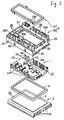
- Figure 1 is an exploded perspective view of an embodiment of a power module in accordance with the present invention
- Figure 2 is an exploded perspective view of the power module taken from a bottom side of Figure 1, illustrating an enclosure wall member, a seal member for a resin, and a heat radiation member;
- Figure 3 is a partially enlarged plan view of the enclosure wall member in the power module
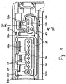
- Figure 4 is a cross section of the enclosure wall member taken along line IV-IV in Figure 3;
- Figure 5 is a perspective view of an FET, illustrating the FET whose leg-like terminals are sealed with a waterproof resin.
- a power module that distributes an electrical power supplied from a common power source on a vehicle or the like to a plurality of electrical loads is described here.
- the present invention is not limited to this power module but can be generally applied to a power module having a heat radiation member and required for waterproof.
- FIG 1 is an exploded perspective view of an embodiment of a power module in accordance with the present invention.
- the power module comprises a power circuit section 1 including a plurality of bus bars 10, a heat radiation member 2 on which the power circuit section 1 is arranged through an insulation layer 5, and a casing 3 for covering the power circuit section 1.
- the casing 3 and heat radiation member 2 are coupled to each other with a seal member 4 for a resin being disposed in the casing 3 to be clamped between them. Under this condition, a waterproof resin is filled in the coupled casing and heat radiation member to form a waterproof layer 6.
- the power circuit section 1 includes: a bus bar assembly plate 11 in which a plurality of bus bars 10 are arranged within a given polygon area (rectangle area in this embodiment), with ends of the bus bars 10 projecting from the same plane in a given pattern (right and left side edges in Figure 1); a plurality ofFETs (field-effect transistors) or semiconductor switching devices 12 interposed between bus bars 10 for input and output terminals; and a control circuit board 13 mounted on one side (front side in Figure 1) of the bus bar assembly plate 11 for controlling a switching operation of the FETs 12.
- the respective FETs 12 are mounted on both bus bar assembly plate 11 and control circuit board 13 to form an electrical connection.
- the power circuit section 1 directly interconnects the bus bar assembly plate 11 and the control circuit board 13 to each other and the respective FETs 12 are electrically connected to them, it is possible to form the power circuit section 1 into a compact size, in particular, in a thickness direction.
- an end of a given bus bar 10 in the bus bar assembly plate 11 is folded up into a given shape to form an external connection terminal 14.
- ends of the bus bars 10, which project from the right and left side edges of the substantially rectangular area on which the bus bars 10 are arranged are folded up substantially in the vertical direction to form the external connection terminals 14.
- These external connection terminals 14 serve as, for example, input terminals to be connected to a common power source on a vehicle, output terminals to be connected to electronic units, or signal input terminals to which a control signal is applied to control a switching operation of the FETs 12.
- the FETs 12 have a substantially rectangular parallelepiped configuration. Each FET 12 is provided on the side surfaces with a plurality of leg-like terminals 12a (two terminals on each side surface in this embodiment). These terminals 12a are electrically connected to the bus bar assembly plate 11 and control circuit board 13. In more detail, a source terminal and a drain terminal of the FET 12 are connected to the bus bar 10 while a gate terminal of the FET 12 is connected to the control circuit board 13.
- the control circuit board 13 includes, for example, a usual printed board. In this embodiment, a thin sheet-like board is used. Through-holes 15 are provided in given positions on the control circuit board 13 (see Figure 5). Each FET 12 is mounted through each through-hole 15 on the bus bar 10.
- bus bar assembly 11 It is possible to change a shape of the bus bar assembly 11 and an arrangement pattern of the bus bars 10, if desired. It is also possible to use another electronic part having a leg-like terminal, such as a relay, an LSI (large-scale integrated circuit), a thyristor or the like in addition to or in lieu of the FET 12. Furthermore, it is possible to arrange the control circuit board 13 above the FET 12.
- the heat radiation member 2 is made of a material having a good heat conductivity, such as an aluminum base metal or the like and is formed into a substantially rectangle in plan view.
- the heat radiation member 2 has a flat circuit arrangement surface 2a at a front side.
- a plurality of heat radiation fins 20 are disposed on the right and left sides (in Figure 2) of a bottom surface of the heat radiation member 2 and extend downwardly.
- a circuit arrangement area is provided on the circuit arrangement surface 2a to support the power circuit section 1.
- the insulation layer 5 is disposed on the circuit arrangement surface 2a to extend over the circuit arrangement area.
- the insulation layer 5 is thermally connected to the heat radiation member 2.
- the insulation layer 5 is formed by applying an adhesive having a high insulation property to the circuit arrangement surface 2a and drying it.
- an adhesive could be include an epoxy base resin, a silicone base adhesive or the like.
- an insulation sheet may be adhered to the circuit arrangement surface 2a.
- the insulation layer 5 is formed by applying an adhesive composing an epoxy base resin having high insulation and good heat conductivity to the circuit arrangement surface 2a.
- the heat radiation fins 20 may be omitted. Alternatively, heat radiation pins may be used in place of the heat radiation fins 20 to project from a side opposite from the circuit arrangement surface 2a.
- the heat radiation fins 20, the heat radiation pins, or the like may be provided on their surfaces with fine grooves to increase their surface areas, thereby enhancing an efficiency of heat radiation.
- the casing 3 is made of an insulation material. As shown in Figures 1 and 2, the casing 3 includes tube-like enclosure wall member 30 and a lid 31 for closing an upper opening 32 in the enclosure wall member 30.
- the enclosure wall member 30, as shown in Figures 1, 2, and 4 includes a wall body 33 whose lower end surface extends along a peripheral edge of the circuit arrangement surface 2a, a skirt 34 that extends downwardly from a periphery of the wall body 33 to cover a peripheral side surface of the heat radiation member 2, and a seal member 4 for a resin provided on the lower end surface of the wall body 33.
- the enclosure wall member 30 can surrounds the power circuit section 1 or the circuit arrangement area of the heat radiation member 2.
- the wall body 33 has a configuration that surrounds the circuit arrangement area of the heat radiation member 2. As shown in Figure 4, the wall body 33 includes a first vertical wall portion 33a, a horizontal wall portion 33b extending inwardly from an end edge of the first vertical wall portion 33a, and a second vertical wall portion 33c extending further upwardly (in a direction opposite from the heat radiation member 2) from an end of the horizontal wall portion 33b.
- the first vertical wall portion 33a is provided in a whole lower end surface with a seal member fitting-groove 35.
- the seal member fitting-groove 35 surrounds the circuit arrangement area of the circuit arrangement surface 2a.
- the seal member 4 for a resin is fitted in the seal member fitting-groove 35.
- a cross sectional shape of the seal member fitting-groove 35 is not limited. In the present embodiment, the seal member fitting-groove 35 is formed into a U-shape in cross section.
- a height of the wall body 33 is greater than that of at least the leg-like terminal 12a of the FET 12 mounted on the power circuit section 1.
- the height of the wall body 33 is greater than those of the respective electronic parts.
- the wall body 33 can surrounds the power circuit section 1 including the respective electronic parts (FETs 12 in this embodiment). In the present invention, the wall body 33 is higher than the FETs 12.
- the wall body 33 is provided so that the upper end opening 32 is opposed to the circuit arrangement area on the circuit arrangement surface 2a. After the enclosure wall member 30 is attached to the heat radiation member 2, the power circuit section 1 disposed on the heat radiation member 2 can be seen through the upper end opening 32.
- the upper end opening 32 is used when the waterproof resin is filled within the enclosure wall member 30.
- the upper end opening 32 serves as a window for an operation of pushing the power circuit section 1 onto the heat radiation member 2 when the power circuit section 1 is connected to the heat radiation member 2.
- the connector housing 36 is integrated with the wall body 33.
- the connector housing 36 includes a bottom portion having terminal through-holes 37 into which the external connection terminals 14 of the power circuit section 1 are inserted, and hoods 38 that surrounds a plurality of external connection terminals 14 projecting through the terminal through-holes 37 in a direction opposite from the circuit arrangement surface 2a.
- the connector housing 36 together with the external connection terminal 14 include an external connection connector adapted to be connected to another connector.
- the connector housing 36 is provided on a bottom with the horizontal wall portion 33b.
- the terminal through-holes 37 are provided in the horizontal wall portion 33b at the opposite sides of the upper end opening 32.
- the external connection terminal 14 of the power circuit section 1 is inserted through the terminal through-hole 37 into the horizontal wall portion 33b.
- the horizontal wall portion 33b is provided on an upper surface with the plural hoods 38 extending toward a direction opposite from the heat radiation member 2 to surround the plural terminal through-holes 37.
- the hoods 38 and horizontal wall position 33b around the terminal through-holes 37 constitute the connector housing 36.
- the connector housings 36 are arranged on the right and left sides of the upper end opening 32 along the longitudinal direction of the wall body 33.
- One or more external connection terminals 14 project into the connector housing 36.
- the connector housing 36 and the one or more external connection terminals 14 constitute the external connection connector that can be connected to another connector.
- the terminal through-hole 37 is formed into a crisscross or a flat shape in cross section.
- a waterproof resin described after can easily pass the terminal through-holes 37 and can flow into the connector housings 36 while keeping an alignment of the terminals 14.
- the shape of the terminal through-hole 37 is not limited. If the terminal through-hole 37 is formed larger than a shape in cross section of the external connection terminal 14, the waterproof resin will easily flow into the connector housing 36. The alignment of the external connection terminals 14 can be obtained, if the terminal through-hole 37 partially overreaches the corresponding cross section of the external connection terminal 14.
- the connector housing 36 is provided in a bottom wall, except a connector contact surface 36a on which a distal end of another connector contacts, with a resin reservoir recess 39 depressed below (toward the heat radiation member 2) the connector contact surface 36a.
- the terminal through-holes 37 are provided in the area in which the resin reservoir recess 39 is formed.
- a resin insertion hole 40 is provided in the inside of the wall body 33 from the resin reservoir recess 39, in particular, the underside of the horizontal wall portion 33b in some connector housings 36.
- the resin reservoir recess 39 reserves the waterproof resin through the terminal through-holes 37.
- a waterproof layer 6 described after is formed in the resin reservoir recess 39 to prevent water from entering the terminal through-hole 37, thereby effectively preventing a short circuit of the power circuit section 1.
- the waterproof resin overflows through the terminal through-holes 37 into the resin reservoir recess 39.
- the resin insertion hole 40 serves to assist in and promote a flow of the waterproof resin from the terminal through-holes 37.
- the waterproof resin flows through the resin insertion hole 40 into the resin reservoir recess 39.
- a shape in plan view and a size of the resin reservoir recess 39 are not limited. However, it is preferable to space an outer peripheral edge of the resin reservoir recess 39 away from the terminal through-holes 37 at a given distance in a plan view. The reason why the outer peripheral edge of the resin reservoir recess 39 is spaced away from the terminal through-holes 37 at a given distance in a plan view is to fill the waterproof resin around the terminal through-holes 37 sufficiently.
- a plurality of terminal through-holes 37 is provided in the resin reservoir recess 39. However, only one terminal through-hole 37 may be provided in the resin reservoir recess 39. In the case where the plural terminal through-holes 37 are provided in the resin reservoir recess 39, as shown in Figure 3, all of the terminal through-holes 37 in the connector housing 36 may be provided in the resin reservoir recess 39 or some of the terminal through-holes 37 may be provided in the resin reservoir recess 39. Even if a plurality of terminal through-holes 37 are provided in the resin reservoir recess 39, a rib is provided between the terminal through-holes 37 and the resin reservoir recesses 39 adjacent the opposite sides of the rib may be communicated with each other.
- a height to a bottom of the resin reservoir recess 39 is set to be greater than a height of an upper edge of the leg-like terminal 12a of the FET 12 upon filling the waterproof resin. That is, the height to the bottom of the resin reservoir recess 39 with respect to the circuit arrangement surface 2a is set to be greater than the upper edge of the leg-like terminal 12a of the FET 12 with respect to the circuit arrangement surface 2a. Accordingly, when the waterproof resin overflows through the resin insertion hole 40 into the resin reservoir recess 39, the leg-like terminal 12a of the FET 12 is sealed within the wall body 33, as shown in Figure 5.
- the height to the bottom of the resin reservoir recess 39 is set to be substantially equal to the height of the FET 12.
- a height to the upper edge of the resin reservoir recess 39 is set to be greater than the height of the FET 12.
- a drainage hole 36c is provided in the horizontal wall portion 33b within the outwardly extending portion 36b of the connector housing 36.
- the drainage hole 36c opens at the outside of the resin seal member 4 and at the side of the heat radiation member 2.
- the drainage hole 36c serves to drain water reserved in the connector housing 36. The water drained from the drainage hole 36c flows through a drainage passage 50 defined between the heat radiation member 2 and the enclosure wall member 30 to the outside.
- the second vertical wall portion 33c is provided in a lower portion with a drainage notch 51 ( Figure 1).
- the water drainage notch 51 is disposed at the same level as or above a surface of the waterproof layer 6.
- the horizontal wall portion 33b is provided on a rear side with a stop projection 52 for stopping the bus bars 10 constituting the external connection terminals 14.
- the skirt 34 is formed into a frame-like configuration surrounding a periphery of the heat radiation member 2.
- a pair of opposed sidewalls of the skirt 34 are formed into projections and depressions corresponding to the heat radiation fins 20.
- the skirt 34 is provided with latch pawls 53 for engaging portions corresponding to the heat radiation member 2.
- the latch pawls 53 firmly couple the enclosure wall member 30 and the heat radiation member 2 to each other.
- the lid 31 is formed into a plate-like configuration corresponding to the upper end opening 32 of the enclosure wall member 30.
- the lid 31 is attached to the enclosure wall member 30 by engagement means (not shown). Although the lid 31 may be omitted, if desired, it will be preferable to provide the lid 31 to avoid a exposure of an interior of the enclosure wall member 30 and to protect the power circuit section 1 from an external impact.
- the seal member 4 for a resin is formed into an annular configuration that surrounds the circuit arrangement area.
- the seal member 4 for a resin serves to prevent the waterproof resin from leaking out from the enclosure wall member 30 until a liquid waterproof resin described after is solidified. Accordingly, the seal member 4 is not required for durability for a long term and can be made of an inexpensive material.
- a material of the seal member 4 is not limited. However, it is preferable to select a material having elasticity (for example, a foam rubber having closed cells) to surely close a clearance between the wall body 33 and the heat radiation member 2.
- a material of the seal member 4 is not limited. A chloroprene rubber or the like will be preferable in view of cost efficiency, general versatility, workability, or the like.
- waterproof layer 6 is explained in connection with a method for producing a power module described after, an explanation of the waterproof layer 6 is omitted here. Next, a method for producing a power module will be explained below.
- a method for producing a power module includes steps of forming the power circuit section 1 and heat radiation member 2 (a power circuit section forming step and a heat radiation member forming step) and steps of forming the enclosure wall member 30 (e.g., an enclosure wall forming-step and a connector housing forming step).
- the seal member 4 for a resin is closely fitted in the seal member fitting-groove 35 in the enclosure wall member 30.
- the power circuit section 1 is attached to the enclosure wall member 30 with the external connection terminals 14 being inserted into the terminal through-holes 37. It is possible to keep an alignment of the external connection terminals 14 by attaching the power circuit section 1 to the enclosure wall member 30 beforehand.
- the same adhesive as that of forming the insulation layer 5 is applied to the circuit arrangement area on the heat radiation member 2.
- the seal member 4 for a resin is closely contacted with the circuit arrangement surface 2a to surround the circuit arrangement area of the heat radiation member 2.
- the enclosure wall member 30, to which the power circuit section 1 is attached, is attached to the heat radiation member 2. Then, the power circuit section 1 is joined to the circuit arrangement area on the circuit arrangement surface 2a of the heat radiation member 2 by means of the adhesive.
- the latch pawls 53 of the skirt 34 engage the heat radiation member 2 to secure the enclosure wall member 30 to the heat radiation member 2.
- the enclosure wall member 30 may be secured to the heat radiation member 2 by mechanical fastening means such as screws, bolts, or the like, chemical means such as an adhesive, or well known attaching means. In the case where the waterproof resin having an adhesive property is used, the enclosure wall member 30 may be attached to the heat radiation member 2 temporarily.
- the same adhesive as that of forming the insulation layer 5 e.g., an adhesive composing an epoxy base resin in the present embodiment
- Another adhesive such as an adhesive having a high heat conductivity may be used.
- the adhesive must form the insulation layer 5 surely. Even if a pinhole is generated in the insulation layer 5 upon forming it, the adhesive for adhering the power circuit section 1 to the heat radiation member 2 embeds the pinhole by an applying work of the adhesive and forms a part of the insulation layer 5. Consequently, the power circuit section 1 is completely insulated from the heat radiation member 2.
- the bus bars 10 disposed on the rear side of the power circuit section 1 are embedded in the adhesive by pressing the power circuit section 1 to join the section 1 to the heat radiation member 2. Consequently, it is possible to prevent a short circuit between the bus bars 10 and to enhance heat conductivity between the power circuit section 1 and the heat radiation member 2.
- the power circuit section 1 is arranged on the circuit arrangement area on the circuit arrangement surface 2a of the heat radiation member 2 (e.g., a circuit arrangement step).
- the enclosure wall member 30 surrounds the circuit arrangement area on the circuit arrangement surface 2a of the heat radiation member 2 including the power circuit section 1 to form an enclosure wall.
- This enclosure wall serves as a bank for the waterproof resin (an enclosure wall forming-step). After performing the enclosure wall forming-step and the circuit arrangement step, a given amount of liquid waterproof resin is filled into a space enclosed by the enclosure wall member 30 and is solidified to form the waterproof layer 6.
- the heat radiation member 2, to which the enclosure wall member 30 and power circuit section 1 are attached is set so that the circuit arrangement surface 2a is faced upwardly.
- the liquid waterproof resin is filled through the upper end opening 32 of the enclosure wall member 30 into the space surrounded by the enclosure wall member 30.
- the waterproof resin is filled into the space until the respective electronic parts (FETs 12) are sealed.
- an amount of waterproof resin is set so that the waterproof resin overflows through the terminal through-holes 37 and resin insertion holes 40 into the connector housing 36 and reaches a given height in the resin reservoir recess 39.
- the bus bar assembly 11 including the base portions of the external connection terminals 14 and the control circuit board 13 are dipped in the waterproof resin.
- the seal member 4 for a resin surrounds the circuit arrangement area, the liquid waterproof resin does not leak out from a clearance between the heat radiation member 2 and the enclosure wall member 30.
- a kind of the waterproof resin is not limited to a special material so long as it has a waterproof property.
- the waterproof resin in a liquid form flows into every corner in the enclosure wall member 30, thereby obtaining a complete seal. If the waterproof resin is used which has certain elasticity and shape retainability after being solidified, it will not affect the FETs 12 and solders.
- a silicone base resin will be preferable in view of electrical insulation as well as heat resistance and cold resistance.
- the waterproof resin having a good adhesive property can omit an applying work of a primer or the like and simplify a work.
- the waterproof resin having a good heat conductive property can promote heat radiation from the waterproof layer 6 as well as the heat radiation member 2, thereby enhancing heat radiation.
- the waterproof layer 6 seals at least a part of the power circuit section 1 within the enclosure wall member 30 and seals the terminal through-holes 37.
- the lid 31 is attached to the enclosure wall member 30 so that the lid 31 covers the upper end opening 32 in the enclosure wall member 30. Because the attachment structure has been described above, an explanation of it will be omitted here. Thus, the power module can be produced.
- the waterproof layer 6 is formed within the enclosure wall member 30 and the waterproof layer 6 seals the bus bar assembly 11 except the external connection terminals 14 of the power circuit section 1, the respective electronic parts such as the FETs 12 and the control circuit board 13, it is possible to effectively waterproof the power circuit section 1. Furthermore, the waterproof layer 6 seals the terminal through-holes 37. Because the terminal through-holes 37 in the connector housing 36 are sealed by utilizing the waterproof layer 6 that seals the power circuit section 1, a simple structure can seal the external connection terminals 14 including the terminal through-holes 37 and can also seal a whole of the power module as well as the connector.
- the connector housing 36 is provided in a bottom portion with the resin reservoir recess 39 and the top surface of the waterproof layer 6 is disposed within the resin reservoir recess 39, it is possible to surely seal the terminal through-holes 37, and to waterproof the external connection terminals 14 including the terminal through-holes 37. Furthermore, because the top surface of the waterproof layer 6 is disposed within the resin reservoir recess 39, it is possible to eliminate a failure upon connection of another connector.
- the waterproof layer 6 formed in the connector housing 36 to seal the terminal through-holes 37 projects from the bottom surface (the horizontal wall portion 33b) of the connector housing 36.
- the waterproof layer 6 will interfere with the distal end of another connector.
- the distal end of another connector contacts with the connector contact surface 36a to be positioned, thereby keeping the connection.
- the waterproof resin is composed of a silicone base resin that has a certain viscosity after being solidified as in the case of the present embodiment, it is possible to avoid problems in which the waterproof resin forming the waterproof layer sticks to another connector, or any layer is generated on a part of the external connection terminal 14 to cause a contact failure.
- the waterproof layer 6 is formed to seal a part of the power circuit section 1 by filling the liquid waterproof resin into the space enclosed by the enclosure wall member 30 and solidifying the resin, it is possible to waterproof the power circuit section 1. Because a part of the waterproof resin flows through the terminal through-holes 37 into the connector housing 36 and the waterproof layer 6 is formed in the connector housing 36 so that the waterproof resin seals the terminal through-holes 37, it is not necessary to add a step of waterproofing the connector and to effectively waterproof a whole of the power module as well as the connector. Furthermore, because the connector can be easily waterproofed, an efficiency of production can be enhanced.
- the height of the bottom surface of the resin reservoir recess 39 is set to be substantially equal to the height of the FET 12, it is possible to seal the power circuit section 1 including the FET 12 when the terminal through-holes 37 are sealed and to waterproof a whole of the power module by a small amount of waterproof resin. Furthermore, when the waterproof resin flows in the resin reservoir recess 39, the waterproof resin will seal the power circuit section 1 including the FETs 12, thereby making a reference for a filling amount of waterproof resin. Because the upper edge of the resin reservoir recess 39 is set to be higher than the upper end of the FET 12, it is possible to seal a whole of the FET 12 by the waterproof layer 6. Under the condition, the waterproof resin will not overflow out of the resin reservoir recess 39. Accordingly, it is possible to keep the connection between the connector housing and another connector while waterproofing a whole of the power module.
- the order of the respective steps is not limited to the above embodiments in which the circuit arrangement step and the enclosure wall forming-step are performed simultaneously.
- the enclosure wall forming-step may follow the circuit arrangement step.
- the enclosure wall forming-step is performed simultaneously with the circuit arrangement step, it will be easier to position the power circuit section 1, thereby enhancing an efficiency of production.
- the connector housing is integrated with the enclosure wall member 30 and the connector forming-step and the enclosure wall forming-step are performed simultaneously.
- the connector housing 36 may be produced independent of the enclosure wall member 30 or may be integrated with the lid 31. It is necessary to dispose a bottom portion of the connector housing 36 below an upper edge of the enclosure wall member 30.
- a shape of the power module is not limited to the shape disclosed in the above embodiment but it may be any shape.
- the waterproof resin is selected from a thermoplastic resin and the waterproof layer 6 is formed when the waterproof resin is solidified.
- a method of forming the waterproof layer 6 is not limited to this manner. Solidifying the waterproof resin naturally while leaving the waterproof resin for a long period in time may form the waterproof layer 6.
Abstract
Description
Claims (13)
- A power module wherein a power circuit section (1) including a plurality of bus bars (10) is disposed upon an insulation layer (5) on a circuit arrangement surface (2a) of a heat radiation member (2), comprising:an external connection terminal (14) formed by folding up an end of each of said bus bars from said circuit arrangement surface;an enclosure wall member (30) disposed on said heat radiation member to surround said power circuit section including said external connection terminal;a connector housing (36) constituting an external connection connector that includes a bottom portion and a hood (38), said bottom portion being provided with a terminal through-hole (37) into which said external connection terminal (14) is inserted, said hood (38) surrounding said external connection terminal (14) that projects through said terminal through-hole (37) toward the opposite side from said circuit arrangement surface, said external connection connector being adapted to be coupled to another connector together with said external connection terminal; anda waterproof layer (6) formed within said enclosure wall member so that at least a part of said power circuit section is sealed and said terminal through-hole (37) is sealed.
- A power module according to Claim 1, wherein said waterproof layer (6) is formed by filling an inside of said enclosure wall member (30) with a liquid waterproof resin, flowing a part of said waterproof resin through said terminal through-hole (37) into said connector housing (36), and solidifying said waterproof resin.
- A power module according to Claim 1 or 2, wherein said connector housing (36) is integrated with said enclosure wall member (33).
- A power module according to one of the foregoing claims, wherein said connector housing (36) is provided in a bottom wall, except a connector contact surface on which a distal end of another connector contacts, with a resin reservoir recess (39) open toward said heat radiation member (2), wherein said terminal through-hole (37) is formed in said resin reservoir recess (39), and wherein a top surface of said waterproof layer is positioned within said resin reservoir recess.
- A power module according to Claim 4, wherein a plurality of terminal through-holes (37) are provided in said resin reservoir recess (39).
- A power module according to any of the foregoing claims, wherein said enclosure wall member (30) comprises a seal member (4) for a resin on an end surface opposed to said heat radiation member (2) so that said seal member (4) is contacted closely with said circuit arrangement surface (2a).
- A method for producing a power module, comprising:arranging on a circuit arrangement surface (2a) of a heat radiation member (2) a power circuit section (1) including a plurality of bus bars (10) and an external connection terminal (14) formed by folding up an end of at least one of said bus bars;attaching closely to said circuit arrangement surface an enclosure wall member (30) that surrounds said power circuit section (1) including said external connection terminal (14);forming an external connection connector adapted to be coupled to another connector through said external connection terminal (14) that is inserted into a terminal through-hole (37) in a connector housing (36), said connector housing including a bottom portion and a hood (38), said bottom portion being provided with said terminal through-hole (37) into which said external connection terminal (14) is inserted, and said hood (38) surrounding said external connection terminal (14) that projects through said terminal through-hole toward the opposite side from said circuit arrangement surface; andforming a waterproof layer (6) for sealing at least a part of said power circuit section (1) and for sealing said terminal through-hole (37) by filling a space enclosed by said enclosure wall member (30) with a liquid waterproof resin, flowing said waterproof resin into said connector housing (36) to a given level, and solidifying said waterproof resin.
- A method for producing a power module according to Claim 7, wherein said enclosure wall member (30) integrated with said connector housing (36) is attached to said circuit arrangement surface (2a) in said second and third steps.
- A method for producing a power module according to Claim 7 or 8, wherein said enclosure wall member (30) comprises a seal member (4) for a resin on an end surface opposed to said heat radiation member (2), and wherein said enclosure wall member (30) is attached to said circuit arrangement surface (2a) in the second step so that said seal member (4) for a resin is contacted closely with said circuit arrangement surface (2a).
- A method for producing a power module according to any of claims 7 through 9, wherein the forming step uses, as a connector housing (36) forming said external connection connector, a connector housing provided in a bottom wall, except a connector contact surface on which a distal end of another connector contacts, with a resin reservoir recess (39) that is open toward said heat radiation member (2) and is provided with said terminal through-hole (37), and wherein the fourth step fills said resin reservoir recess (39) with said waterproof resin until a top surface of said waterproof layer reaches a given level in said resin reservoir recess (39).
- A method for producing a power module according to Claim 10, wherein the third step uses, as a connector housing (36) forming said external connection connector, a connector housing provided in a bottom wall, except a connector contact surface on which a distal end of another connector contacts, with a resin reservoir recess (39) that is open toward said heat radiation member (2) and is provided with said terminal through-hole (37), and wherein the fourth step fills said resin reservoir recess (39) with said waterproof resin until a top surface of said waterproof layer reaches a given level in said resin reservoir recess (39).
- A method for producing a power module according to any of claims 7 through 11, wherein the arranging step uses, as a power circuit section (1) to be arranged on a circuit arrangement area, a power circuit section including one or more electronic parts (12) having a leg-like terminal (12a), and wherein the third step uses, as a connector housing (36) forming said external connection connector, a connector housing in which a bottom surface of said resin reservoir recess (39) is set to be higher than an upper end of said leg-like terminal (12a) upon filling of said waterproof resin.
- A method for producing a power module according to any of claims 7 through 12, wherein the forming step uses, as a connector housing (36) forming said external connection connector, a connector housing in which an upper edge of said resin reservoir recess (39) is set to be higher than an upper end of said electronic parts (12) upon filling of said waterproof resin.
Applications Claiming Priority (2)
| Application Number | Priority Date | Filing Date | Title |
|---|---|---|---|
| JP2003036469A JP4155048B2 (en) | 2003-02-14 | 2003-02-14 | Power module and manufacturing method thereof |
| JP2003036469 | 2003-02-14 |
Publications (2)
| Publication Number | Publication Date |
|---|---|
| EP1448037A2 true EP1448037A2 (en) | 2004-08-18 |
| EP1448037A3 EP1448037A3 (en) | 2008-02-06 |
Family
ID=32677632
Family Applications (1)
| Application Number | Title | Priority Date | Filing Date |
|---|---|---|---|
| EP03026187A Withdrawn EP1448037A3 (en) | 2003-02-14 | 2003-11-17 | Power module and method for producing the same |
Country Status (3)
| Country | Link |
|---|---|
| US (1) | US7035105B2 (en) |
| EP (1) | EP1448037A3 (en) |
| JP (1) | JP4155048B2 (en) |
Cited By (4)
| Publication number | Priority date | Publication date | Assignee | Title |
|---|---|---|---|---|
| CN103313508A (en) * | 2012-03-12 | 2013-09-18 | 矢崎总业株式会社 | Electronic component board and production method of the same |
| CN106797113A (en) * | 2014-10-15 | 2017-05-31 | 株式会社美姿把 | The manufacture method of controller and controller |
| TWI677273B (en) * | 2018-01-18 | 2019-11-11 | 飛宏科技股份有限公司 | Waterproof structure for preventing water from penetrating into electronic products and waterproof annular ring |
| US20210291766A1 (en) * | 2020-03-19 | 2021-09-23 | Ellenberger & Poensgen Gmbh | Power distributor of an electrical system of a motor vehicle |
Families Citing this family (42)
| Publication number | Priority date | Publication date | Assignee | Title |
|---|---|---|---|---|
| JP2004221256A (en) * | 2003-01-14 | 2004-08-05 | Auto Network Gijutsu Kenkyusho:Kk | Circuit assembly and its manufacturing method |
| DE112005001446T5 (en) * | 2004-06-24 | 2007-05-31 | Kabushiki Kaisha Yaskawa Denki, Kitakyushu | motor control |
| JP4466256B2 (en) * | 2004-07-29 | 2010-05-26 | アイシン・エィ・ダブリュ株式会社 | Electronic control unit for automatic transmission |
| US7633008B2 (en) | 2005-03-08 | 2009-12-15 | Autonetworks Technologies, Ltd. | Electrical connection box |
| JP2006303106A (en) * | 2005-04-19 | 2006-11-02 | Denso Corp | Electronic circuit device |
| JP2006325356A (en) * | 2005-05-20 | 2006-11-30 | Auto Network Gijutsu Kenkyusho:Kk | Electrical connection box |
| JP4594198B2 (en) * | 2005-09-02 | 2010-12-08 | 株式会社オートネットワーク技術研究所 | Electrical junction box |
| US7393236B2 (en) | 2005-09-02 | 2008-07-01 | Gm Global Technology Operations, Inc. | Integrated thermal and electrical connection system for power devices |
| JP2007165588A (en) * | 2005-12-14 | 2007-06-28 | Omron Corp | Power module structure, and solid-state relay using same |
| US7593235B2 (en) * | 2006-07-20 | 2009-09-22 | Power Integrations, Inc. | Thermal conduit |
| JP4694514B2 (en) * | 2007-02-08 | 2011-06-08 | トヨタ自動車株式会社 | Semiconductor device cooling structure |
| JP4385058B2 (en) * | 2007-05-07 | 2009-12-16 | 三菱電機株式会社 | Electronic control unit |
| US7773379B2 (en) * | 2007-10-23 | 2010-08-10 | Tyco Electronics Corporation | Module assembly having heat transfer plate |
| JP4986053B2 (en) * | 2007-11-07 | 2012-07-25 | 住友電装株式会社 | Electrical junction box |
| JP2009124874A (en) * | 2007-11-15 | 2009-06-04 | Sumitomo Wiring Syst Ltd | Electrical junction box |
| DE102008040501A1 (en) * | 2008-07-17 | 2010-01-21 | Robert Bosch Gmbh | Improved heat dissipation from a control unit |
| US8027168B2 (en) * | 2008-08-13 | 2011-09-27 | Delphi Technologies, Inc. | Electrical center with vertical power bus bar |
| US8248809B2 (en) * | 2008-08-26 | 2012-08-21 | GM Global Technology Operations LLC | Inverter power module with distributed support for direct substrate cooling |
| TW201032029A (en) * | 2009-02-24 | 2010-09-01 | Acbel Polytech Inc | Detachable heat dissipating package structure for intermediate bus converter (IBC) |
| DE102009029476B4 (en) * | 2009-09-15 | 2012-11-08 | Lisa Dräxlmaier GmbH | Electronic device for switching currents and manufacturing method for the same |
| US8169779B2 (en) * | 2009-12-15 | 2012-05-01 | GM Global Technology Operations LLC | Power electronics substrate for direct substrate cooling |
| JP5538019B2 (en) * | 2010-03-25 | 2014-07-02 | 新電元工業株式会社 | Connector unit and electronic circuit device |
| JP5257554B2 (en) * | 2010-04-19 | 2013-08-07 | トヨタ自動車株式会社 | Electronic component housing member and power conversion device |
| US8446733B2 (en) | 2010-11-24 | 2013-05-21 | Lear Corporation | Printed circuit board connection assembly |
| JP2013098273A (en) * | 2011-10-31 | 2013-05-20 | Auto Network Gijutsu Kenkyusho:Kk | Circuit structure |
| JP6044109B2 (en) * | 2012-05-09 | 2016-12-14 | 三菱電機株式会社 | High voltage part potting structure and high voltage part potting method |
| JP6210449B2 (en) * | 2013-04-12 | 2017-10-11 | パナソニックIpマネジメント株式会社 | Lighting device |
| JP6213329B2 (en) * | 2014-03-24 | 2017-10-18 | 株式会社オートネットワーク技術研究所 | Power distribution board |
| JP6355994B2 (en) * | 2014-07-09 | 2018-07-11 | 株式会社ユーシン | Waterproof structure of control device |
| JP6287659B2 (en) * | 2014-07-22 | 2018-03-07 | 株式会社オートネットワーク技術研究所 | Circuit structure |
| WO2016060046A1 (en) * | 2014-10-15 | 2016-04-21 | 株式会社ミツバ | Controller and method for manufacturing controller |
| JP6281707B2 (en) * | 2014-10-23 | 2018-02-21 | 住友電装株式会社 | Electrical junction box |
| CN104319982B (en) * | 2014-11-04 | 2016-09-07 | 国家电网公司 | A kind of power equipment cabinet attachment means |
| JP6287815B2 (en) * | 2014-12-24 | 2018-03-07 | 株式会社オートネットワーク技術研究所 | Method for manufacturing circuit structure |
| US9293870B1 (en) * | 2015-03-10 | 2016-03-22 | Continental Automotive Systems, Inc. | Electronic control module having a cover allowing for inspection of right angle press-fit pins |
| US9781850B1 (en) * | 2016-05-25 | 2017-10-03 | Continental Automotive Systems, Inc. | Press-fit contact window cover retention |
| JP6852513B2 (en) * | 2017-03-30 | 2021-03-31 | 株式会社オートネットワーク技術研究所 | Circuit equipment |
| US10103478B1 (en) * | 2017-06-23 | 2018-10-16 | Amazon Technologies, Inc. | Water resistant connectors with conductive elements |
| FR3076175B1 (en) * | 2017-12-22 | 2020-01-10 | Valeo Siemens Eautomotive France Sas | REMOTE WALL ELECTRICAL EQUIPMENT |
| US11088066B2 (en) * | 2018-03-19 | 2021-08-10 | Tactotek Oy | Multilayer structure and related method of manufacture for electronics |
| JP7208757B2 (en) * | 2018-10-03 | 2023-01-19 | 川崎重工業株式会社 | Control device |
| JP7127498B2 (en) * | 2018-11-09 | 2022-08-30 | 住友電装株式会社 | Heat dissipation material and electric connection box |
Citations (5)
| Publication number | Priority date | Publication date | Assignee | Title |
|---|---|---|---|---|
| EP0547877A2 (en) | 1991-12-16 | 1993-06-23 | Mitsubishi Denki Kabushiki Kaisha | Semiconductor power module |
| US5646827A (en) | 1991-05-31 | 1997-07-08 | Nippondenso Co., Ltd. | Electronic device having a plurality of circuit boards arranged therein |
| JPH11204700A (en) | 1998-01-19 | 1999-07-30 | Hitachi Ltd | Power module integrating heat radiating fin |
| US6282092B1 (en) | 1998-06-12 | 2001-08-28 | Shindengen Electric Manufacturing Co., Ltd. | Electronic circuit device and method of fabricating the same |
| JP2002344177A (en) | 2001-05-17 | 2002-11-29 | Denso Corp | Electronic device |
Family Cites Families (3)
| Publication number | Priority date | Publication date | Assignee | Title |
|---|---|---|---|---|
| JPS6261856A (en) * | 1985-09-12 | 1987-03-18 | Yazaki Corp | Wiring device assembled with functions for automobile |
| US4899256A (en) * | 1988-06-01 | 1990-02-06 | Chrysler Motors Corporation | Power module |
| DE69129407T2 (en) * | 1991-07-10 | 1998-11-19 | Samsung Electronics Co Ltd | Movable monitor |
-
2003
- 2003-02-14 JP JP2003036469A patent/JP4155048B2/en not_active Expired - Fee Related
- 2003-10-24 US US10/691,502 patent/US7035105B2/en not_active Expired - Fee Related
- 2003-11-17 EP EP03026187A patent/EP1448037A3/en not_active Withdrawn
Patent Citations (5)
| Publication number | Priority date | Publication date | Assignee | Title |
|---|---|---|---|---|
| US5646827A (en) | 1991-05-31 | 1997-07-08 | Nippondenso Co., Ltd. | Electronic device having a plurality of circuit boards arranged therein |
| EP0547877A2 (en) | 1991-12-16 | 1993-06-23 | Mitsubishi Denki Kabushiki Kaisha | Semiconductor power module |
| JPH11204700A (en) | 1998-01-19 | 1999-07-30 | Hitachi Ltd | Power module integrating heat radiating fin |
| US6282092B1 (en) | 1998-06-12 | 2001-08-28 | Shindengen Electric Manufacturing Co., Ltd. | Electronic circuit device and method of fabricating the same |
| JP2002344177A (en) | 2001-05-17 | 2002-11-29 | Denso Corp | Electronic device |
Cited By (7)
| Publication number | Priority date | Publication date | Assignee | Title |
|---|---|---|---|---|
| CN103313508A (en) * | 2012-03-12 | 2013-09-18 | 矢崎总业株式会社 | Electronic component board and production method of the same |
| CN103313508B (en) * | 2012-03-12 | 2016-01-27 | 矢崎总业株式会社 | Substrate for electronic elements and manufacture method thereof |
| CN106797113A (en) * | 2014-10-15 | 2017-05-31 | 株式会社美姿把 | The manufacture method of controller and controller |
| US10117341B2 (en) | 2014-10-15 | 2018-10-30 | Mitsuba Corporation | Controller and manufacturing method thereof |
| TWI677273B (en) * | 2018-01-18 | 2019-11-11 | 飛宏科技股份有限公司 | Waterproof structure for preventing water from penetrating into electronic products and waterproof annular ring |
| US20210291766A1 (en) * | 2020-03-19 | 2021-09-23 | Ellenberger & Poensgen Gmbh | Power distributor of an electrical system of a motor vehicle |
| US11653450B2 (en) * | 2020-03-19 | 2023-05-16 | Ellenberger & Poensgen Gmbh | Power distributor of an electrical system of a motor vehicle |
Also Published As
| Publication number | Publication date |
|---|---|
| JP2004248426A (en) | 2004-09-02 |
| US20040160731A1 (en) | 2004-08-19 |
| EP1448037A3 (en) | 2008-02-06 |
| US7035105B2 (en) | 2006-04-25 |
| JP4155048B2 (en) | 2008-09-24 |
Similar Documents
| Publication | Publication Date | Title |
|---|---|---|
| US7035105B2 (en) | Power module and method for producing the same | |
| US6911598B2 (en) | Casing unit for circuit assembly and method for producing the circuit assembly | |
| US7099155B2 (en) | Distribution unit and electric connection box including the same | |
| US6924985B2 (en) | Method of waterproofing power circuit section and power module having power circuit section | |
| US7736158B2 (en) | Electrical junction box with a decreased height size and waterproof function | |
| EP1806960B1 (en) | Electronic device | |
| US7749134B2 (en) | Control module | |
| JP4682762B2 (en) | Electronic device, lighting device, and lighting fixture | |
| JP4002427B2 (en) | Method for manufacturing circuit structure | |
| JP2005080370A (en) | Circuit configuration and manufacturing method of waterproofed circuit configuration | |
| US20050257950A1 (en) | Electrical connection box and manufacturing method thereof | |
| JP2004088989A (en) | Method for waterproofing power circuit section | |
| JP4059097B2 (en) | Circuit structure | |
| JP4110995B2 (en) | Circuit structure and inspection method thereof | |
| JP4197970B2 (en) | Power distribution unit and electrical junction box including the power distribution unit | |
| JP4146332B2 (en) | Waterproof structure of electronic unit | |
| JPS62208696A (en) | Electronic controller housing case | |
| JP4150962B2 (en) | Waterproof structure of electrical unit | |
| JP2004031417A (en) | Water-proof method for power-circuit unit | |
| JP2004260959A (en) | Waterproof structure of electric connection box | |
| JP3917473B2 (en) | Power module | |
| JP2006013273A (en) | Semiconductor device | |
| JP4686264B2 (en) | Electrical junction box | |
| WO2022264814A1 (en) | Electrical junction box | |
| JPH0623254U (en) | PCB fixing structure |
Legal Events
| Date | Code | Title | Description |
|---|---|---|---|
| PUAI | Public reference made under article 153(3) epc to a published international application that has entered the european phase |
Free format text: ORIGINAL CODE: 0009012 |
|
| 17P | Request for examination filed |
Effective date: 20031205 |
|
| AK | Designated contracting states |
Kind code of ref document: A2 Designated state(s): AT BE BG CH CY CZ DE DK EE ES FI FR GB GR HU IE IT LI LU MC NL PT RO SE SI SK TR |
|
| AX | Request for extension of the european patent |
Extension state: AL LT LV MK |
|
| PUAL | Search report despatched |
Free format text: ORIGINAL CODE: 0009013 |
|
| AK | Designated contracting states |
Kind code of ref document: A3 Designated state(s): AT BE BG CH CY CZ DE DK EE ES FI FR GB GR HU IE IT LI LU MC NL PT RO SE SI SK TR |
|
| AX | Request for extension of the european patent |
Extension state: AL LT LV MK |
|
| AKX | Designation fees paid |
Designated state(s): DE FR |
|
| 17Q | First examination report despatched |
Effective date: 20100707 |
|
| STAA | Information on the status of an ep patent application or granted ep patent |
Free format text: STATUS: THE APPLICATION IS DEEMED TO BE WITHDRAWN |
|
| 18D | Application deemed to be withdrawn |
Effective date: 20160601 |