EP1450331B1 - Method of displaying position of aircraft in display device for air traffic control - Google Patents
Method of displaying position of aircraft in display device for air traffic control Download PDFInfo
- Publication number
- EP1450331B1 EP1450331B1 EP02802057A EP02802057A EP1450331B1 EP 1450331 B1 EP1450331 B1 EP 1450331B1 EP 02802057 A EP02802057 A EP 02802057A EP 02802057 A EP02802057 A EP 02802057A EP 1450331 B1 EP1450331 B1 EP 1450331B1
- Authority
- EP
- European Patent Office
- Prior art keywords
- aircraft
- marks
- traffic control
- air traffic
- mark
- Prior art date
- Legal status (The legal status is an assumption and is not a legal conclusion. Google has not performed a legal analysis and makes no representation as to the accuracy of the status listed.)
- Expired - Lifetime
Links
Images


Classifications
-
- G—PHYSICS
- G08—SIGNALLING
- G08G—TRAFFIC CONTROL SYSTEMS
- G08G5/00—Traffic control systems for aircraft, e.g. air-traffic control [ATC]
- G08G5/0047—Navigation or guidance aids for a single aircraft
- G08G5/0052—Navigation or guidance aids for a single aircraft for cruising
-
- G—PHYSICS
- G08—SIGNALLING
- G08G—TRAFFIC CONTROL SYSTEMS
- G08G5/00—Traffic control systems for aircraft, e.g. air-traffic control [ATC]
- G08G5/0017—Arrangements for implementing traffic-related aircraft activities, e.g. arrangements for generating, displaying, acquiring or managing traffic information
- G08G5/0026—Arrangements for implementing traffic-related aircraft activities, e.g. arrangements for generating, displaying, acquiring or managing traffic information located on the ground
-
- G—PHYSICS
- G08—SIGNALLING
- G08G—TRAFFIC CONTROL SYSTEMS
- G08G5/00—Traffic control systems for aircraft, e.g. air-traffic control [ATC]
- G08G5/0073—Surveillance aids
- G08G5/0078—Surveillance aids for monitoring traffic from the aircraft
Definitions
- the present invention relates to a method for displaying aircraft positions in a display system for air traffic control, which is capable of visually grasping the flight status of aircraft under air traffic control on a display screen, and which is particularly appropriate for the surveillance and the air traffic control of the flight status of multiple aircraft that come close to each other within a safety distance.
- a conventional surveillance radar system based on air traffic control information obtained from various kinds of radars, multiple range rings indicating a distance from a reference point on a runway on a ground surface, the symbols indicating aircraft under air traffic control, the data tag indicating the data including the flight number, the velocity and the altitude of the aircraft, and a lead line indicating relationships between the symbol and the data tag are displayed in two dimensions on a display screen, while the displayed status is renewed at certain cycles (scan cycles). And a controller has watched the display position of a symbol and learned the contents of a data tag to perform air traffic control.
- the position of aircraft which actually exists in three dimensions, is displayed in a visually recognizable form by a symbol only in terms of position in an XY plane.
- the position of the aircraft in a Z axis direction i.e., the altitude of the aircraft is displayed by a numerical value. Therefore, when the controller performs air traffic control work, he or she needs to combine the visually recognizable symbol and the altitude represented by the numerical value so as to image the flight status of the aircraft and needs to perform required air traffic control work, imaging the flight status. He or she needs to have a great deal of experience and make much effort before he or she can accurately image the flight status based on the position of the symbol and the numerical value.
- When multiple aircraft exist in an air traffic control area there is a possibility that he or she incorrectly images the flight status since he or she bears a heavy burden. There is a possibility that his or her incorrect image causes near miss or midair collision.
- JP-A-2000-155900 Some technologies to avoid the occurrence of near miss or midair collision of aircraft are listed in JP-A-2000-155900, which is to predict the approach to the ground or collision with an aircraft. More specifically, three-dimensional elevation data of the terrain of an air traffic control area are stored, an estimated arrival range of the aircraft is set up based on the position and the velocity vector of the aircraft, a finite difference vector is found based on the position of the aircraft and the elevation data, and it is determined based on the finite difference vector and the velocity vector of the aircraft whether the above-mentioned elevation data are in the estimated arrival range of the above-mentioned aircraft.
- 3D three dimensions
- a method for displaying aircraft positions which is characterized in that the method comprises displaying a terrain apparently in three dimensions on a display screen based on topographic data corresponding to an air space under air traffic control; finding three-dimensional positions of aircrafts based on position data and altitude data of the respective aircrafts contained in air traffic control information obtained about the air space under air traffic control, and displaying aircraft marks indicating the respective aircrafts at positions on the display screen so as to correspond to the three-dimensional positions of the respective aircrafts; finding an inter-distance between two neighboring aircraft, and determining whether the distance found is shorter than a preset threshold value; and displaying a surveillance instruction mark apparently in three dimensions on the display screen, the surveillance instruction mark comprising a triangle having three apexes, the three apexes comprising the aircraft marks of the two neighboring aircraft and a point having a specific relationship with the aircraft marks, when it is determined that the distance found is shorter than the threshold value.
- any one of (a) a mark comprising a triangle having three apexes, which comprise the aircraft marks corresponding to the two neighboring aircraft, and a position that is apart from one of the aircraft marks along a vertical line extending perpendicular to the one aircraft toward a ground surface of the terrain by a distance corresponding to an altitude difference between both aircraft on the display screen; (b) a mark comprising a triangle having three apexes, which comprise both aircraft marks, and a projection point of one of the aircraft marks projected onto the ground surface of the terrain; and (c) a mark comprising a composition of two triangles, one of which has three apexes comprising one of the aircraft marks, and projection points of both aircraft marks projected onto the ground surface of the terrain, and the other of which has three apexes comprising the other aircraft mark, and the projection points of both aircraft marks projected onto the ground surface of the terrain.
- the method according to the first aspect is characterized in that the surveillance instruction mark is one of (a) a mark comprising a triangle having three apexes, which comprise the aircraft marks corresponding to the two neighboring aircrafts, and a position that is apart from one of the aircraft marks along a vertical line extending perpendicular to the one aircraft toward a ground surface by a distance corresponding to an altitude difference between both aircrafts on the display screen; (b) a mark comprising a triangle having three apexes, which comprise both aircraft marks, and a projection point of one of the aircraft marks projected onto the ground surface; and (c) a mark comprising a composition of two triangles, one of which has three apexes comprising one of the aircraft marks, and projection points of both aircraft marks projected onto the ground surface of the terrain, and the other of which has three apexes comprising the other aircraft mark, and the projection points of both aircraft marks projected onto the ground surface of the terrain.
- the method according to the first or second aspect is characterized in that the method further comprises finding the distance between the two neighboring aircraft based on the position data and the altitude data with respect to the two neighboring aircraft; and displaying the surveillance instruction mark with different display properties according to which one of multiple stages of the distance ranges indicating a degree of approach is applied to, when the aircraft distance between the aircraft is shorter than the threshold value.
- the method according to the third aspect is characterized in that the display properties of the surveillance instruction mark are set so as to have stronger appeal as the degree of approach between both aircrafts increases.
- the method according to the first, second, third or fourth aspect is characterized in that travel directions and ground speeds of the two neighboring aircraft are indicated by vectors based on travel direction data and ground speed data contained in the air traffic control information transmitted from the two neighboring aircraft, the vectors extending from the respective aircraft marks in the respective travel directions and having graduations.
- the method according to the first, second, third, fourth or fifth aspect is characterized in that the vertical lines extending from the respective aircraft marks onto the ground surface of the terrain are painted in different colors to see whether each of the aircraft is ascending or descending.
- the method according to the first, second, third, fourth or fifth aspect is characterized in that the vertical lines extending from the respective aircraft marks onto the ground surface of the terrain are painted in different colors to see whether each of the aircraft is ascending or descending, and that ground speed levels of the aircrafts are indicated by different thicknesses of the vertical lines.
- the method according to any one of the first to seventh aspects is characterized in that the aircraft marks are stored as reduced stereoscopic models, which have respective sizes proportional to sizes of the respective aircraft; and the aircraft marks of the respective aircraft are displayed by the reduced stereoscopic models of the respective aircraft based on call signs contained in the air traffic control information obtained about the air space under air traffic control.
- the method according to the eighth aspect is characterized in that the reduced stereoscopic models are displayed so as to have attitudes accorded with respective travel directions based on travel direction data contained in the air traffic control information or based on respective travel directions determined based on respective flight trajectories of the aircraft obtained by processing the air traffic control information.
- a method which is characterized in that the method comprises 1) displaying a terrain apparently in three dimensions on a display screen based on topographic data corresponding to an air space under air traffic control; 2) finding three-dimensional positions of respective aircrafts based on position data and altitude data of the respective aircraft contained in air traffic control information obtained about the air space under air traffic control, and displaying aircraft marks indicating the respective aircrafts at positions on the display screen so as to correspond to the three-dimensional positions of the respective aircrafts; 3) finding a distance between two neighboring aircraft, and determining whether the distance between two aircraft found is shorter than a threshold value preset as a safety distance; 4) displaying a surveillance instruction mark and a warning mark apparently in three dimensions on the display screen when it is determined that the distance between two aircraft found is shorter than the threshold value, wherein the surveillance instruction mark comprises a triangle having three apexes, which comprise the aircraft marks corresponding to the two neighboring aircraft, and a position that
- the determination of whether the inter-aircraft distance is shorter than the threshold value in the tenth aspect is characterized to be performed so that when it is determined that the inter-aircraft distance is shorter than the threshold value, a triangle is formed so as to have three apexes comprising the aircraft marks corresponding to the two neighboring aircraft, and a position that is apart from one of the aircraft marks along a vertical line extending perpendicular to the one aircraft toward the ground surface of the terrain by the distance corresponding to the altitude difference between both aircraft on the display screen, and that a triangular pyramid is displayed as a warning mark when protective ranges for both aircraft after a certain period of time are supposed to be overlapped each other according to flight prediction performed based on flight trajectories and flight conditions of the two neighboring aircraft, the warning mark connecting the three apexes of the triangle and a point in an overlapped range for both aircrafts.
- the method according to any one of the first to eleventh aspects is characterized in that the aircraft marks are displayed in an interpolated way by displaying the aircraft marks on the display screen based on latest air traffic control information obtained about the respective aircrafts, following by performing processing of interpolation by making use of flight trajectory information of the respective aircraft until obtaining next air traffic control information.
- the method according to the twelfth aspect is characterized in that when display has been renewed based on the latest air traffic control information, the aircraft marks are displayed not only in the interpolated way but also in a emphatic way for recognition of renewal.
- an aircraft position display system generally comprises a data processing unit 1, a display unit 3 provided on a control console 2, and an input unit 4 connected to the display unit as shown in Fig. 1.
- the data processing unit 1 includes an air traffic control information collection unit 100, a control unit 200 for processing collected air traffic control information for the purpose of accomplishing a desired purpose and for performing control operation, and a storage unit 300 for storing data originally prepared, data to be inputted from outside and data as a result of data processing by the control unit 200, respectively.
- the air traffic control information collection unit 100 collects air traffic control information containing certain data, including the call sign (flight name), the current position, the travel direction and the ground speed of an aircraft existing in an air traffic control area (air space).
- Collection of the air traffic control information may be performed by inputting data obtained from a known traffic control radar system into the air traffic control information collection unit 100 as disclosed in JP-A-8-110380, JP-A-9-304526, JP-A-11-174150 and JP-A-2001-148100, or instead by inputting data obtained by a combination of a radar system as disclosed in JP-A-9-5432 and a GPS (Global Positioning System) into the air traffic control information collection unit 100.
- a known traffic control radar system into the air traffic control information collection unit 100 as disclosed in JP-A-8-110380, JP-A-9-304526, JP-A-11-174150 and JP-A-2001-148100, or instead by inputting data obtained by a combination of a radar system as disclosed in JP-A-9-5432 and a GPS (Global Positioning System) into the air traffic control information collection unit 100.
- GPS Global Positioning System
- each of aircrafts is provided with a GPS and a responder, and each of the aircrafts replies with data, including the call sign, the travel direction and the ground speed of the aircraft, added to the position data and the altitude data obtained from the GPS in response to an interrogation from a ground station (control station), the replied data may be inputted into the air traffic control information collection unit 100.
- the storage unit 300 has a system program for accomplishing the functions of the aircraft position display system stored therein and includes an air traffic control information memory 301 for storing control data collected by the air traffic control information collection unit 100, a topographic data memory 302 for storing topographic data of an airport and its surrounding area, an aircraft mark memory 303 for storing three-dimensional images of aircraft marks (symbols) symbolically showing the aircrafts, a distance between aircraft data memory 304, a reference data memory 305 and a surveillance instruction mark memory 306.
- an air traffic control information memory 301 for storing control data collected by the air traffic control information collection unit 100
- a topographic data memory 302 for storing topographic data of an airport and its surrounding area
- an aircraft mark memory 303 for storing three-dimensional images of aircraft marks (symbols) symbolically showing the aircrafts
- a distance between aircraft data memory 304 a reference data memory 305
- Air traffic control information which has been collected by the air traffic control information collection unit 100, is stored in the air traffic control information memory 301 for each flight number of each aircraft. Since the air traffic control information is inputted from, e.g., the traffic control radar system at certain intervals (scan cycles), air traffic control information inputted in a certain period of time and the latest air traffic control information renewed with respect to aircraft existing in an area under air traffic control are stored in the air traffic control information memory 301.
- The.latest air traffic control information is utilized as the current position data (X, Y, Z), the current travel direction data and the current ground speed data of the aircraft existing in the area.
- the air traffic control information in the certain period of time is utilized for analysis of flight trajectory data and, if needed, for flight prediction.
- the topographic data memory 302 has a three-dimensional reduced model space of the terrain of the area under air traffic control (such as an airport and a surrounding area within about 100 Km of it) stored as an image data therein.
- the image data may be arbitrarily changed according to an airport to apply the present invention.
- the three-dimensional reduced model space means a stereoscopic model space, which is provided by showing the actual space surrounding an airport in a reduced scale for display on the display unit 3.
- each of the aircraft marks to be stored in the aircraft mark memory 303 may be formed from, e.g., a recognizable dot, a sign of X or a sign of ⁇ , each of the aircraft marks are formed as a reduced stereoscopic model having a size proportional to the size of the corresponding aircraft in a preferred embodiment of the present invention.
- the actual sizes of aircraft may be classified into multiple kinds, such as a large size, a medium size and a small size, and the reduced stereoscopic models showing aircraft marks may be shown by using reduced stereoscopic models symbolically showing the sizes of respective kinds of aircrafts.
- the aircraft mark memory 303 has the call signs and the identification codes of the reduced stereoscopic models of the respective aircrafts stored so as to be mapped each other therein.
- the aircraft mark of an aircraft is shown in a reduced stereoscopic model, which has a size proportional to the actual size of the aircraft or has a shape symbolically showing the size of the aircraft.
- the distance between two aircraft data memory 304 serves to temporarily store the distance between two neighboring aircrafts, when the distance between two aircraft is found by calculation as stated later.
- the safety distance is defined according to the flight frequency or the degree of congestion in the area surrounding each airport and ranges from RNP4 (4 miles) to RNP10 (10 miles) at the present stage.
- the reference data memory 305 has a threshold value as the reference stored therein to determine whether the distance between two aircraft is shorter than the safety distance.
- reference data are stored for determination of multiple stages according to the degree of approach between both aircraft when the distance between two aircraft is shorter than the threshold value: e.g., Stage 1 in the case of a small approach (wherein the distance between both aircraft is from 8 to not shorter than 5 miles for instance), Stage 2 in the case of medium approach (wherein the distance between two aircraft is from shorter than 5 miles to not shorter than 2 miles for instance), and Stage 3 in the case of a great approach (wherein the distance between two aircraft is shorter than 2 miles for instance).
- Stage 1 in the case of a small approach (wherein the distance between both aircraft is from 8 to not shorter than 5 miles for instance)
- Stage 2 in the case of medium approach (wherein the distance between two aircraft is from shorter than 5 miles to not shorter than 2 miles for instance)
- Stage 3 in the case of a great approach (wherein the distance between two aircraft is shorter than 2 miles for instance).
- the surveillance instruction mark memory 306 has surveillance instruction marks stored therein so that a surveillance instruction mark, which is prepared in the processing of surveillance instruction mark preparation, can be displayed on the display unit 3 as stated later when the distance between two aircraft is shorter than the safety distance.
- the control unit 200 includes a 3D graphic engine section 201, a graphic engine section 202, an image composition section 203, an operation section 204, an initial setup section 205 and a display control section 206, each of which is made of software.
- the control unit 200 performs search in the air traffic control information memory 301 at certain periods to ascertain whether air traffic control information is stored. If in the affirmative, the control unit provides the air traffic control information to the 3D graphic engine section 201.
- the 3D graphic engine section 201 has three functions of preparation of three-dimensional images for displaying the positions of aircrafts with an aircraft marks (symbols) by using the latest air traffic control information for the respective aircraft stored in the air traffic control information memory 301, preparation of a three-dimensional map for displaying the terrain surrounding an airport by using the topographic data, and preparation of a surveillance instruction mark wherein the surveillance instruction mark is prepared in order that the positions of two aircrafts within the safe distance and changing relative statuses between the aircraft are displayed to draw a controller's attention.
- aircraft marks symbols
- the 3D graphic engine section 201 obtains relevant calls sign in the air traffic control information given from the air traffic control information memory 301 through the control unit 200, reads aircraft marks from the aircraft mark memory 303 by using the identification codes corresponding to the call signs, and prepares aircraft marks, each of which is formed from a reduced stereoscopic model having a size proportional to the size of the aircraft or a reduced stereoscopic model symbolically showing the kind of the aircraft in terms of size.
- the 3D graphic engine section 201 When the reduced stereoscopic model of a aircraft mark has a form symbolically showing the kind of the aircraft in terms of size, the 3D graphic engine section 201 has a relevant call sign inputted thereto and prepares an aircraft mark forming from a reduced stereoscopic model corresponding to the kind of the aircraft in terms of size by using the identification code corresponding to the call sign.
- the 3D graphic engine section 201 is configured to perform the preparation of aircraft marks so that the direction (attitude) of the aircraft marks corresponding to respective aircrafts are displayed so as to accord with the travel directions of the respective aircraft on a display screen based on the travel direction data contained in the air traffic control information.
- the graphic engine section 202 is connected to the 3D graphic engine section 201.
- the graphic engine section 202 converts the three-dimensional images of aircraft marks, a terrain and a surveillance instruction mark prepared by the 3D graphic engine section into computer image data for two-dimensional display in order that the converted images are displayed on the display screen of the display unit 3 so as to correspond to the positions of the aircrafts.
- the image composition section 203 serves to perform composition by overwriting, on a map data, the image data of aircraft marks and a surveillance mark or a warning mark stated later, which are obtained from the graphic engine section 202.
- the display control section 206 in the control unit 200 is connected to the display unit 3, which displays an airport control image in three dimensions based on composition of the image data of the aircraft marks and the topographic data.
- the composite data as the two-dimensional display data, which have been obtained by the image composition section 203, are provided to the display unit 3 to be displayed under the control of the display control section 206.
- the control unit 200 has the initial setup section 205 housed therein to set the rotation angle of display on the display screen by the display unit 206 at start.
- the rotation angle is set at an initial set value, and the terrain surrounding an airport is displayed on the display unit 3 based on the image data outputted from the graphic engine section 202 while the aircraft marks are displayed at certain coordinate positions in the displayed terrain.
- the display unit 3 has the input unit 4 comprising a visual point change unit provided thereto and in the vicinity thereof and is connected to the control unit 200.
- the visual point change unit is configured to be capable of specifying a rotation angle parameter by, e.g., a keyboard or a trackball.
- a controller performs manipulation to change the rotation angle on the display screen at an arbitrary time by modifying the rotation angle, when an image composed by the image composition section 203 is displayed on the display unit 3. In other words, it is possible to change the display state (angle) in a three-dimensional image for airport control according to visual point changing manipulation at the visual point change unit.
- the operation section 204 performs calculation processing for calculating the distance between aircrafts existing in the area under air traffic control, first determination processing for determining by comparison with the threshold value whether the distance between two aircraft calculated is smaller than the safety distance, and second determination processing wherein, when the distance between two aircraft is determined as being shorter than the safety distance, it is determined which one of Stage 1, Stage 2 and Stage 3 the degree of approach is applied to.
- the operation section has a calculation processing function for calculating the distance between two aircraft, a first determination processing function for determining whether the calculated value is longer or shorter than the threshold value and a second determination processing function for determining the degree of approach when the calculated value is less than the threshold value.
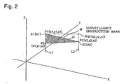
- the difference in altitude between the two aircraft (z1-z2) is found based on these position data at first place, and the position data (x1, y1, z2) of a position P3, which is apart from the position of one of the aircraft (e.g., A1) by the distance corresponding to the difference in altitude (z1-z2) between the two aircraft (A1, A2) along the perpendicular line L1 perpendicularly extending from the one aircraft to the ground surface, is prepared at the second place.
- the position that is lowered from the position P1 of the aircraft A1 having a higher altitude by the difference in altitude along the perpendicular line L1 as in the example shown in Fig. 2 is defined as P3
- the position that is raised from the position P2 of the aircraft A2 having a lower altitude by the difference in altitude along the perpendicular line L2 as shown dotted lines in Fig. 2 may be defined as P3.
- a triangle is prepared so as to have P1 (x1, y1, z1), P2 (x2, y2, z2) and P3 (x1, y1, z2), or P1 (x1, y1, z1), P2 (x2, y2, z2) and P3 (x2, y2, z1) as three apexes.
- D (x1 - x2) 2 + (y1 - y2) 2 + (z1 - z2) 2
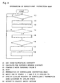
- the operation section 108 compares the value of D as the distance between aircraft with the threshold value T set and stored in the reference data storage 305 as the first determination processing function (S3). When D is smaller than T, the operation section outputs a caution signal, which is inputted in the 3D graphic engine section 201.
- the 3D graphic engine section 201 performs the preparation of a surveillance instruction mark wherein the surveillance instruction mark (M in Fig. 2) is prepared so as to comprise a triangle having the three apexes at the coordinate positions P1, P2 and P3 corresponding to the triangle (x1, y1, z2) having the three apexes at the coordinate positions P1, P2 and P3, which in turn correspond to the position data (x1, y1, z1), (x2, y2, z2) and (x1, y1, z2) relevant to the caution signal (S5).
- the surveillance instruction mark thus prepared is stored in the surveillance instruction mark memory 306.
- the operation section 108 subsequently performs the second determination processing function to determine which one of Stages 1 to 3 indicating the degree of approach the value D of the distance between two aircraft is applied to (S6), outputs either one of a signal indicating Stage 1, a signal indicating Stage 2 and a signal indicating Stage 3 according to applied Stage and generates a specific signal specifying a display property according to the outputted stage signal so as to be capable of easily distinguishing which one of stages the surveillance instruction mark is applied to (S7), and outputs the specific signal to the graphic engine section 202 (S8).
- a display property, which has small appeal to, e.g., a controller watching the display screen, is specified since it is a stage wherein the two aircraft have made a small approach and the degree of danger is still low.
- a display property, which has relatively greater appeal to, e.g. the controller is specified since it is a stage wherein the two aircraft have made a medium approach and the degree of danger is slightly higher.
- a display property, which has greater appeal to, e.g. the controller is specified since it is a stage wherein the two aircrafts have made a great approach and the degree of danger is higher.
- the display control section 206 displays the surveillance instruction mark M having a certain display property on the display screen based on the specific signal.
- Stage 3 it is preferable from the viewpoint of ensuring attention that the surveillance instruction mark M is flickered or that a beep is generated from a speaker (not shown) attached to the display unit 3.
- the identification codes corresponding to relevant call signs contained in the collected air traffic control information are read from the aircraft mark memory 303, and the aircraft are displayed with aircraft marks S3 and S4, which comprise reduced stereoscopic models having sizes corresponding to the identification codes.
- the 3D graphic engine section 201 Based on the travel direction data contained in the collected air traffic control information, the 3D graphic engine section 201 performs image processing to display the aircraft marks in such attitudes so as to accord with the actual travel directions of the respective aircrafts.
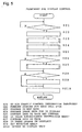
- the air traffic control information collection unit 100 When the system starts, it is first checked whether the air traffic control information collection unit 100 has air traffic control information inputted therein or not (S21). Whenever air traffic control information is newly inputted, the newly inputted information is stored in the air traffic control information memory 301 for each call sign to accumulate the air traffic control information for a certain period of time (S22).
- relevant topographic data are read from the topographic data memory 302, and the 3D graphic engine section 201 prepares 3D map data based on the relevant topographic data (S23). Subsequently, based on the air traffic control information stored in the air traffic control information memory 301, the 3D graphic engine section 201 performs processing of preparation of image data for 3D display in order to display the aircraft marks at positions on the display screen so as to correspond to the actual positions of the aircrafts (S24).
- the reduced stereoscopic models having sizes corresponding to the sizes of the aircrafts are read from the air traffic control information memory 301, and the attitudes (directions) of the reduced stereoscopic models are determined so as to accord with the travel directions contained in the air traffic control information.
- the graphic engine section 202 converts the 3D map data and the image data for 3D display of the aircraft marks into two-dimensional data for two-dimensional display on the display unit 3 and overwrites the aircraft marks on the map data to compose both data (S25).
- the surveillance instruction mark memory 306 is accessed to check whether there is the prepared surveillance instruction mark or not (S26). When there is the surveillance instruction mark, the surveillance instruction mark is also overwritten on the two-dimensional data to be composed (S27). It is checked whether the input unit 3 of the control desk 3 is manipulated to input a change in display or not (S28). When there is the surveillance instruction mark, this processing is immediately performed. When there is no surveillance instruction mark, this processing is performed after composition of the data.
- the display control section 206 provides the display unit 3 with the data for screen display outputted from the graphic engine section 202 with a rotation angle specified by the initial setup section 205 being maintained (S210).
- the data for screen display outputted from the graphic engine section 202 is set at the inputted rotation angle for screen display in accordance with the manipulation (S29) and is outputted to the display unit 3 (S210).
- aircraft marks S5 to S9 which are represented by reduced stereoscopic models having sizes proportional to the sizes of the respective aircrafts, are displayed at positions corresponding to the actual positions of the respective aircrafts with certain angles to the ground surface in the background showing an airport and its surrounding space represented apparently in three dimensions on the display screen 3' of the display unit 3 so that the attitudes of the aircraft marks accord with the travel directions of the respective aircraft.
- the operation section 204 is provided with a function of Kalman Filter to find the estimated arrival position of an aircraft at the next scan time with respect to the current position of the aircraft based on the air traffic control information stored in the period from the latest scan cycle to the scan cycle several times before with respect to the aircraft in the air traffic control information memory 301, i.e., the flight trajectory data.
- the aircraft mark for the aircraft is apparently repeatedly displayed in a section from the display position for the current position of the aircraft to the display position for the estimated arrival position at the next scan time by being displayed in a successively or intermittently staggered fashion in the section until the aircraft mark based on the air traffic control information at the next scan time is displayed.
- surveillance instruction marks M1 and M2 are displayed in the section between aircraft A6 and A7 and in the section between aircrafts A8 and P9 since the distance between the aircrafts A6 and A7 and the distance between the aircrafts A8 and P9 are shorter than the safety distance, respectively.
- the vertical side of the triangle indicating one of the surveillance instruction marks extends perpendicularly from the aircraft mark for the one of the aircraft (A6 or A9).
- the surveillance instruction marks it is obviously understandable for one of the neighboring pair of aircraft to have a higher altitude than the other (A7 or A8), and it is possible to easily estimate the degree of the altitude difference based on the length of the vertical side.
- the relative positional relationship is displayed by a surveillance instruction mark M, which has different display properties according to the degree of approach.
- the surveillance instruction mark exhibits a display property having greater appeal.
- Air traffic control information is sequentially inputted at certain cycles.
- the surveillance instruction mark varies momentarily and dynamically in terms of shape and display mode according to the positions, the altitudes and the travel directions, and a change in the relative positional relationship with respect to two aircrafts displayed at both ends of an upper side of the surveillance instruction mark displayed on the display screen.
- the surveillance instruction mark M3 is not formed in a triangle shape but a single straight line since both aircrafts have an almost equal altitude.
- the straight line is thin, the straight line is inferior in terms of visibility.
- the processing of preparation of the surveillance instruction mark is performed so that the straight line is enough thick to have sufficient visibility.
- the display property of the surveillance instruction mark changes in such a way so as to gradually increase a controller's attention. Conversely, when aircrafts are flying in directions of being apart from each other, the display property of the surveillance instruction mark changes in such a way so as to gradually decrease the controller's attention.
- the controller can grasp the flight status of respective aircraft comprehensively and visually from the display screen.
- a surveillance instruction mark is displayed, he or she can adequately determine whether air control is needed on not, paying his or her attention to the changing status of the surveillance instruction mark.
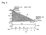
- the surveillance instruction mark requiring severe surveillance and its surrounding area can be displayed in enlargement as shown in Fig. 4. It is possible to change the rate of enlargement by making the pushing time of the cursor key longer or shorter.
- Fig. 4 Although other display contents are omitted in Fig. 4 for simply showing a basic portion, aircraft data including call signs, altitudes and ground speeds, are displayed in data tags DT in the vicinity of the display positions for the respective aircraft marks S3 and S4 as usual. By clicking a data tag DT with the cursor key, it is possible to use a well-known surveillance radar system provided outside the system to transmit a required flight control command to the relevant aircraft.
- the relative positional relationship between two aircrafts is represented by the surveillance instruction mark M, M1 or M2.
- the altitude difference between both aircraft is obvious at a glance in comparison with a case wherein the surveillance instruction mark is represented by a trapezoid, which connects four points: two projection points of both aircrafts projected onto the ground surface and the two aircraft marks of the aircrafts.
- the surveillance instruction mark has an advantage to be capable of making the altitude difference of both aircrafts clear even when the altitude difference is small.
- the surveillance instruction mark may be displayed in different kinds of compositions and display patterns as shown in Figs. 7(a), 7(b) and 7(c) as examples.
- the mode shown in Fig. 7(a), which has been stated, is a case wherein the surveillance instruction mark is a mark Ma comprising a triangle having, as three apexes, the aircraft marks S1 and S2 corresponding to two neighboring aircrafts A1 and A2, and the position P3 that is apart from one of the aircraft marks along the vertical line PL extending perpendicular to the one aircraft toward the ground surface of the terrain by a distance corresponding to the altitude difference between both aircraft on the display screen.
- the surveillance instruction mark is a mark Ma comprising a triangle having, as three apexes, the aircraft marks S1 and S2 corresponding to two neighboring aircrafts A1 and A2, and the position P3 that is apart from one of the aircraft marks along the vertical line PL extending perpendicular to the one aircraft toward the ground surface of the terrain by a distance corresponding to the altitude difference between both aircraft on the display screen.
- the surveillance instruction mark is a mark Mb comprising a triangle having, as three apexes, both aircraft marks S1 and S2, and the projection point ep1 (or ep2) of one of the aircraft marks S1 (or S2) projected onto the ground surface of the terrain.
- the surveillance instruction mark is a mark Mb comprising a triangle having, as three apexes, both aircraft marks S1 and S2, and the projection point ep1 (or ep2) of one of the aircraft marks S1 (or S2) projected onto the ground surface of the terrain.
- the surveillance instruction mark is a mark Mc comprising a composition of two triangles, one of which has, as three apexes, one of the aircraft marks S1, and the projection points ep21 and ep2 of both aircraft marks projected onto the ground surface of the terrain, and the other of which has, as three apexes, the other aircraft mark S2, and the projection points ep1 and ep2 of both aircraft marks projected onto the ground surface of the terrain.
- the surveillance instruction mark is a mark Mc comprising a composition of two triangles, one of which has, as three apexes, one of the aircraft marks S1, and the projection points ep21 and ep2 of both aircraft marks projected onto the ground surface of the terrain, and the other of which has, as three apexes, the other aircraft mark S2, and the projection points ep1 and ep2 of both aircraft marks projected onto the ground surface of the terrain.
- the surveillance instruction mark may be a mark Mb' comprising a composition of two triangles, one of which has, as three apexes, both aircraft marks S1 and S2, and the projection point ep1 of one of the aircraft marks S1 projected onto the ground surface of the terrain, and the other of which has, as three apexes, both aircraft marks and the projection point ep2 of the other aircraft mark S2 projected onto the ground surface of the terrain.
- the surveillance instruction mark is not a triangle shape but a straight line as indicated by a symbol S1 in Fig. 7(a).
- This mode is inferior in terms of visibility when the two aircrafts are closer to each other.
- the shape of the surveillance instruction mark is changing as shown in Figs. 7 (a)(1), 7 (a)(2) and 7 (a) (3) when the degree of approach between the two aircraft becomes greater, this mode has a disadvantage in that a controller pays lesser attention since the displayed area is reduced as the degree of approach increases.
- the surveillance instruction mark becomes a straight line because of an equal altitude as shown in Fig. 7(a), it is preferable that the straight line is thicker to improve visibility.
- the modes shown in Figs. 7(b) and (c) have an advantage in that even if two aircraft have an equal altitude, the surveillance instruction mark does not lose a triangle shape, and that even if the degree of approach increases as shown in Figs. 7(b)(1), 7(b)(2) and 7(b)(3), and 7(c)(1), 7(c)(2) and 7(c)(3), the controller can continuously pay attention.
- the surveillance instruction mark is displayed irrespective of the flight directions of respective aircrafts since the initial stage wherein neighboring aircrafts have come into the distance under surveillance.
- a controller who watches the display screen has to pay equal attention to all surveillance instruction marks displayed even in a case wherein he or she can pay less attention by recognizing the flight directions of aircrafts with a surveillance instruction mark applied thereto.
- the representation provided by the system is supposed to be one of the reasons for his or her fatigue.
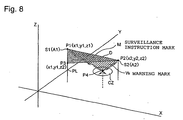
- Fig. 8 shows another embodiment according to the present invention wherein it is possible to eliminate the disadvantage caused by displaying only the surveillance instruction mark as stated earlier.
- a warning mark having a specific shape is displayed on the display screen to provide a warning so as to reliably recognize an increased risk of collision in a case wherein after a surveillance instruction mark has been displayed because of two neighboring aircraft entering a distance to be under surveillance, it is determined that the protective air spaces for both aircrafts conflict each other.
- the surveillance instruction mark comprises a triangle having, as three apexes, the aircraft marks S1 and S2 corresponding to two neighboring aircraft A1 and A2, and the position P3 that is apart from one of the aircraft mark along the vertical line PL extending perpendicular to the one aircraft toward the ground surface by a distance corresponding to the altitude difference between both aircrafts on the display screen as in the example shown in Fig. 2, flight prediction up to lapse of a certain period of time is performed based on the flight trajectories and the flight conditions.
- a point of mark is formed in the conflicted range, and a warning mark W, which comprises a triangle having the point of mark and both aircraft marks as three apexes, is displayed apparently in three dimensions on the display screen 3'.
- Fig. 9 shows a schematic view of flight prediction in a case wherein it is supposed that two aircrafts A1 and A2 have entered a distance to be under surveillance.
- Positions P-3, P-2 and P-1 are examples of positions that are plotted three cycles earlier (-t3, -t2 and -t1) than the current position P0 of an aircraft Ax. These series of position data show the flight trajectories.
- the operation section 204 performs prediction by calculating estimated arrival positions P1, P2 to P5 and further after lapse of each of the scan periods at t1, t2 to t5 and later with respect to the current position P0 based on the flight trajectories and the flight conditions given with respect to the respective aircraft.
- the operation section outputs a conflict prediction signal containing the position data of the overlapped air spaces to provide the signal to the 3D graphic engine section 201.
- the 3D graphic engine section 201 forms a point P4 in a conflict zone CZ on the display screen corresponding to the overlapped air spaces as shown in Fig. 8.
- the 3D graphic engine section generates a triangle, i.e., a warning mark W having the point P4 and the aircraft marks S1 and S2 of both aircrafts as three apexes.
- the warning mark W in addition to the surveillance instruction mark M is displayed on the display screen 3' as shown in Fig. 8. Since aircraft, the flight directions of which are crossing, are provided with the warning mark W formed with a triangle having a point in the conflict-predicted air space (CZ) and both aircraft marks as the apexes (P4, P1, P2) as stated earlier, the warning mark W is clearly displayed even when both aircraft have an equal altitude. Accordingly, it is possible to effectively prevent a controller from overlooking the warning mark W.
- each of the surveillance instruction mark and the warning mark is displayed as a single straight line. Although it is supposed that such a case would not actually occur, it is possible to avoid an error in visual recognition by making the straight lines thicker and flicking the straight lines.
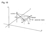
- the shape shown in Fig. 10 may be adopted in addition to the triangle stated earlier.
- a triangle is created so as to have, as three apexes, the aircraft marks S1 and S2 corresponding to two neighboring aircrafts, and the position P3 that is apart from one of the aircraft mark along the vertical line extending perpendicular to the one aircraft toward the ground surface of the terrain by a distance corresponding to the altitude difference between both aircrafts on the display screen.
- flight prediction is performed based on the flight trajectories and the flight conditions, and when the protective air spaces for both aircrafts conflict each other, a triangular pyramid is created so as to connect a point P4 in the conflicted range and the three apexes of the triangle and is utilized as the warning mark W.
- the air traffic control information contains ground speed data and travel direction data in some cases.
- the air traffic control information about one aircraft is collected and stored at certain cycles while the aircraft exists in an air space under air traffic control. It is preferable that the flight trajectory of each of aircraft is formed by making use of these data, and that a combination of the flight trajectory and a velocity indicating vector DV having graduations at certain intervals showing speeds is displayed so as to extend behind an aircraft mark S.
- a combination of the flight trajectory and a velocity indicating vector DV having graduations at certain intervals showing speeds is displayed so as to extend behind an aircraft mark S.
- the terrain of an air space under air traffic control is displayed apparently in three dimensions on the display screen
- the aircraft marks of aircraft existing in the air space are displayed apparently in three dimensions on the display screen so as to correspond to the three-dimensional positions of the aircraft
- two neighboring aircraft, the distance between which is determined to be shorter than a distance to be under surveillance is provided with a surveillance instruction mark having a certain shape apparently in three dimensions on the display screen.
- the display property of a surveillance instruction mark is set so as to have stronger appeal as the degree of approach between both aircrafts increases.
- multiple surveillance instruction marks are displayed, it is possible to perform effective surveillance work by giving priority to two aircrafts having a high risk. Accordingly, it is effective to avoid an accident.
- respective aircraft marks are displayed so as to be accompanied by velocity indicating vectors. Accordingly, it is easy to perform the flight prediction of aircraft, which are closer to each other than the safety distance. Since the surveillance work can be performed with an increase or decrease in the degree of danger between two aircraft being predicted, it is possible to reduce the mental burden of a controller.
- respective aircraft marks are displayed so as to be accompanied by velocity indicating vectors
- the vertical lines from the aircrafts are painted in different colors to see whether each of the aircraft is ascending or descending
- the ground speeds of the aircraft are shown by differences in the thicknesses of the vertical lines. Accordingly, it is effective to more precisely determine the degree of danger between two aircrafts existing within a distance to be under surveillance.
- the aircraft mark of an aircraft can be displayed by a reduced stereoscopic model corresponding to the size of the aircraft based on a call sign contained in the air traffic control information obtained with respect to an air space under air traffic control. Since a controller can visually recognize the size of the aircraft only by watching the aircraft mark displayed on the display screen, he or she can perform adequate surveillance work, which is suited for the size of the aircraft.
- the attitude of a reduced stereoscopic model showing the aircraft mark is displayed so as to accord with the travel direction. Accordingly, it is possible to momentarily and visually recognize the flight direction of the aircraft only by watching the aircraft mark on the display screen. It is also possible to prevent a controller from issuing a wrong control command due to misrecognition in terms of the flight direction.
- the occurrence of conflict is predicted, and a warning mark is displayed. Accordingly, it is possible to invite a controller' attention more effectively and reliably than a case wherein a surveillance instruction mark is displayed only when the aircrafts are closer to each other than the safe distance.
- a warning mark is displayed so as to have a triangular pyramid shape, which is superior to the triangle warning mark in the tenth aspect in terms of visibility.
- the display positions of an aircraft mark from the current scan time to the next scan time can be stored and displayed. It is possible to effectively avoid misunderstanding of a flight status, which can be created because the aircraft mark is failed to be displayed momentarily under the influence of the scan cycle.
Description
Claims (13)
- A method for displaying aircraft positions, the method comprising the steps
displaying a terrain apparently in three dimensions on a display screen based on topographic data corresponding to an air space under air traffic control;
finding three-dimensional positions of respective aircraft based on position data and altitude data of the respective aircraft contained in air traffic control information obtained about the air space under air traffic control, and displaying aircraft marks indicating the respective aircraft at positions on the display screen so as to correspond to the three-dimensional positions of the respective aircraft;
finding a distance between two neighboring aircraft, and determining whether the distance between two aircraft found is shorter than a safety distance; and
displaying a surveillance instruction mark apparently in three dimensions on the display screen, the surveillance instruction mark comprising a triangle having three apexes, the three apexes comprising the aircraft marks of the two neighboring aircraft and a position having a specific relationship with the aircraft marks, when it is determined that the distance between two aircraft found is shorter than the safety distance. - The method according to Claim 1, characterized in that the surveillance instruction mark is one of (a) a mark comprising a triangle having three apexes, which comprise the aircraft marks corresponding to the two neighboring aircraft, and a position that is apart from one of the aircraft marks along a vertical line extending perpendicularly to the one aircraft toward a ground surface by a distance corresponding to an altitude difference between both aircraft on the display screen; (b) a mark comprising a triangle having three apexes, which comprise both aircraft marks, and a projection point of one of the aircraft marks projected onto the ground surface; and (c) a mark comprising a composition of two triangles, one of which has three apexes comprising one of the aircraft marks, and projection points of both aircraft marks projected onto the ground surface of the terrain, and the other of which has three apexes comprising the other aircraft mark, and the projection points of both aircraft marks projected onto the ground surface of the terrain.
- The method according to Claim 1 or 2, characterized in that the method further comprises finding the inter-aircraft distance between the two neighboring aircraft based on the position data and the altitude data with respect to the two neighboring aircraft; and displaying the surveillance instruction mark with different display properties according to which one of multiple stages of distance ranges indicating a degree of approach is applied to, when the distance between two aircraft is shorter than the defined safety distance.
- The method according to Claim 3, characterized in that the display properties of the surveillance instruction mark are set so as to have stronger appeal as the degree of approach between both aircraft increases.
- The method according to Claim 1, 2, 3 or 4, characterized in that travel directions and ground speeds of the two neighboring aircraft are indicated by vectors based on travel direction data and ground speed data contained in the air traffic control information transmitted from the two neighboring aircraft, the vectors extending from the respective aircraft marks in the respective travel directions and having graduations.
- The method according to Claim 1, 2, 3, 4 or 5, characterized in that the vertical lines extending from the respective aircraft marks onto the ground surface of the terrain are painted in different colors to see whether each of the aircraft is ascending or descending.
- The method according to Claims 6, characterized in that ground speed levels of the aircraft are indicated by different thicknesses of the vertical lines.
- The method according to any one of Claims 1 to 7, characterized in that the aircraft marks are stored as reduced stereoscopic models, which have respective sizes proportional to sizes of the respective aircraft; and the aircraft marks of the respective aircraft are displayed by the reduced stereoscopic models of the respective aircraft based on call signs contained in the air traffic control information obtained about the air space under air traffic control.
- The method according to Claim 8, characterized in that the reduced stereoscopic models are displayed so as to have attitudes accorded with respective travel directions based on travel direction data contained in the air traffic control information or based on respective travel directions determined based on respective flight trajectories of the aircraft obtained by processing the air traffic control information.
- A method for displaying aircraft positions according to claim 1
further comprising the step of displaying a warning mark apparently in three dimensions on the display screen when it is determined that the distance between two aircraft found is shorter than the safety distance, wherein one of the three apexes of the triangle of the surveillance instruction mark comprises a position that is apart from one of the aircraft marks along a vertical line extending perpendicularly to the one aircraft toward a ground surface by a distance corresponding to an altitude difference between both aircraft on the display screen, and wherein the warning mark comprises a triangle having three apexes, which comprise a point in an overlapped range and both aircraft marks, when estimated arrival ranges of both aircraft after a certain period of time are supposed to be overlapped on each other according to a prediction of flight up to lapse of the certain period of time, which is performed based on flight trajectories and flight conditions of the two neighboring aircraft. - A method for displaying aircraft positions according to claim 1, wherein one of the three apexes of the triangle comprises a position that is apart from one of the aircraft marks along a vertical line extending perpendicularly to the one aircraft toward the ground surface of the terrain by the distance corresponding to the altitude difference between both aircraft on the display screen, the method further comprising the step of displaying a triangular pyramid as a warning mark in a three-dimension-like way when estimated arrival ranges for both aircraft after a certain period of time are supposed to be overlapped on each other according to a flight prediction performed based on flight trajectories and flight conditions of the two neighboring aircraft, the warning mark connecting the three apexes of the triangle and a point in an overlapped range for both aircraft.
- The method according to any one of Claims 1 to 11, characterized in that the aircraft marks are displayed in an interpolated way by displaying the aircraft marks on the display screen based on latest air traffic control information obtained about the respective aircraft, following by performing processing of interpolated display by making use of flight trajectories of the respective aircraft until obtaining next air traffic control information.
- The method according to Claim 12, characterized in that, when display has been renewed based on the latest air traffic control information, the aircraft marks are displayed in a stressed way for recognition of renewal.
Applications Claiming Priority (3)
| Application Number | Priority Date | Filing Date | Title |
|---|---|---|---|
| JP2001325991A JP3579685B2 (en) | 2001-10-24 | 2001-10-24 | Aircraft position display method in display device for air traffic control |
| JP2001325991 | 2001-10-24 | ||
| PCT/JP2002/011001 WO2003036585A1 (en) | 2001-10-24 | 2002-10-23 | Method of displaying position of aircraft in display device for air traffic control |
Publications (3)
| Publication Number | Publication Date |
|---|---|
| EP1450331A1 EP1450331A1 (en) | 2004-08-25 |
| EP1450331A4 EP1450331A4 (en) | 2005-05-25 |
| EP1450331B1 true EP1450331B1 (en) | 2005-12-28 |
Family
ID=19142451
Family Applications (1)
| Application Number | Title | Priority Date | Filing Date |
|---|---|---|---|
| EP02802057A Expired - Lifetime EP1450331B1 (en) | 2001-10-24 | 2002-10-23 | Method of displaying position of aircraft in display device for air traffic control |
Country Status (6)
| Country | Link |
|---|---|
| US (1) | US7030780B2 (en) |
| EP (1) | EP1450331B1 (en) |
| JP (1) | JP3579685B2 (en) |
| DE (1) | DE60208438T2 (en) |
| HK (1) | HK1071627A1 (en) |
| WO (1) | WO2003036585A1 (en) |
Cited By (1)
| Publication number | Priority date | Publication date | Assignee | Title |
|---|---|---|---|---|
| US7965227B2 (en) | 2006-05-08 | 2011-06-21 | Era Systems, Inc. | Aircraft tracking using low cost tagging as a discriminator |
Families Citing this family (66)
| Publication number | Priority date | Publication date | Assignee | Title |
|---|---|---|---|---|
| US7889133B2 (en) * | 1999-03-05 | 2011-02-15 | Itt Manufacturing Enterprises, Inc. | Multilateration enhancements for noise and operations management |
| US7667647B2 (en) | 1999-03-05 | 2010-02-23 | Era Systems Corporation | Extension of aircraft tracking and positive identification from movement areas into non-movement areas |
| US7777675B2 (en) | 1999-03-05 | 2010-08-17 | Era Systems Corporation | Deployable passive broadband aircraft tracking |
| US7612716B2 (en) * | 1999-03-05 | 2009-11-03 | Era Systems Corporation | Correlation of flight track data with other data sources |
| US7782256B2 (en) | 1999-03-05 | 2010-08-24 | Era Systems Corporation | Enhanced passive coherent location techniques to track and identify UAVs, UCAVs, MAVs, and other objects |
| US7570214B2 (en) * | 1999-03-05 | 2009-08-04 | Era Systems, Inc. | Method and apparatus for ADS-B validation, active and passive multilateration, and elliptical surviellance |
| US8203486B1 (en) | 1999-03-05 | 2012-06-19 | Omnipol A.S. | Transmitter independent techniques to extend the performance of passive coherent location |
| US8446321B2 (en) | 1999-03-05 | 2013-05-21 | Omnipol A.S. | Deployable intelligence and tracking system for homeland security and search and rescue |
| US7576695B2 (en) * | 1999-03-05 | 2009-08-18 | Era Systems Corporation | Multilateration enhancements for noise and operations management |
| US7739167B2 (en) | 1999-03-05 | 2010-06-15 | Era Systems Corporation | Automated management of airport revenues |
| US7908077B2 (en) | 2003-06-10 | 2011-03-15 | Itt Manufacturing Enterprises, Inc. | Land use compatibility planning software |
| US7779361B2 (en) * | 2004-02-09 | 2010-08-17 | Malmstrom R Dean | Change-alarmed, integrated console apparatus and method |
| WO2006101417A1 (en) * | 2005-03-24 | 2006-09-28 | Zakrytoe Aktsionernoe Obschestvo 'volga-Dnepr Airlines' | Aircraft cockpit (variants) |
| US7330147B2 (en) * | 2005-04-21 | 2008-02-12 | Honeywell International Inc. | System and method for ground proximity warning with enhanced obstacle depiction |
| EP1911675A4 (en) * | 2005-06-08 | 2010-12-08 | Toshio Tsuyuki | Navigation system |
| JP4590559B2 (en) * | 2005-06-21 | 2010-12-01 | 沖電気工業株式会社 | Human interface device for ordering and spacing in air traffic control consoles |
| US7286062B2 (en) * | 2005-06-29 | 2007-10-23 | Honeywell International, Inc. | Perspective view conformal traffic targets display |
| DE102005035746B4 (en) * | 2005-07-29 | 2010-02-18 | Siemens Ag | Method for determining a relative position of a mobile unit by comparing scans of an environment and mobile unit |
| GB2433796A (en) | 2005-12-23 | 2007-07-04 | Nats Plc | Air traffic control system |
| GB2433795A (en) * | 2005-12-23 | 2007-07-04 | Nats | Air traffic control system |
| US20070222665A1 (en) * | 2006-03-07 | 2007-09-27 | Koeneman Robert L | Airborne Situational Awareness System |
| JP2007272642A (en) * | 2006-03-31 | 2007-10-18 | Nec Corp | Radar display device and display method for airport traffic control tower |
| WO2007115359A1 (en) * | 2006-04-10 | 2007-10-18 | Windbidco Pty Ltd | Display system for controlling aircraft traffic and method |
| GB0613054D0 (en) | 2006-06-30 | 2006-08-09 | Nats En Route Plc | Air traffic control |
| GB0613055D0 (en) | 2006-06-30 | 2006-08-09 | Nats En Route Plc | Air traffic control |
| JP4821529B2 (en) * | 2006-09-19 | 2011-11-24 | 富士ゼロックス株式会社 | Image display apparatus and program |
| US20080198157A1 (en) * | 2007-02-16 | 2008-08-21 | Honeywell International, Inc. | Target zone display system and method |
| JP4998354B2 (en) * | 2008-03-31 | 2012-08-15 | 日本電気株式会社 | Display device for control tower, aircraft display method and display control program used for display device for control tower |
| US8094188B1 (en) * | 2008-04-01 | 2012-01-10 | Rockwell Collins, Inc. | System, apparatus, and method for enhancing the image presented on an aircraft display unit through location highlighters |
| US8089375B1 (en) * | 2008-06-09 | 2012-01-03 | Rockwell Collins, Inc. | Head-up display/synthetic vision system predicted flight path depiction |
| FR2933523B1 (en) * | 2008-07-01 | 2014-04-18 | Airbus France | METHOD AND DEVICE FOR ASSISTING THE DRIVING OF A VEHICLE, IN PARTICULAR AN AIRCRAFT, FOR THE AVOIDANCE OF OBSTACLES |
| FR2936309B1 (en) * | 2008-09-22 | 2010-11-05 | Airbus France | METHOD FOR MONITORING THE FLIGHT OF AN AIRCRAFT |
| US8032268B2 (en) * | 2008-09-29 | 2011-10-04 | Honeywell International Inc. | Methods and systems for indicating whether an aircraft is below a minimum altitude criterion for a sector |
| US8849477B2 (en) * | 2008-10-14 | 2014-09-30 | Honeywell International Inc. | Avionics display system and method for generating three dimensional display including error-compensated airspace |
| US8040258B2 (en) * | 2009-04-07 | 2011-10-18 | Honeywell International Inc. | Enhanced situational awareness system and method |
| US8362925B2 (en) * | 2009-05-05 | 2013-01-29 | Honeywell International Inc. | Avionics display system and method for generating flight information pertaining to neighboring aircraft |
| JP5535604B2 (en) * | 2009-12-11 | 2014-07-02 | 三菱重工業株式会社 | Control display system, method and program |
| FR2955687B1 (en) * | 2010-01-26 | 2017-12-08 | Airbus Operations Sas | SYSTEM AND METHOD FOR MANAGING ALARM SOUND MESSAGES IN AN AIRCRAFT |
| FR2958759B1 (en) * | 2010-04-09 | 2012-11-16 | Airbus Operations Sas | METHOD AND DEVICE FOR RECLAIMING THE POSITION OF AN AIRCRAFT ON A FLIGHT |
| DE102010023162A1 (en) * | 2010-06-09 | 2011-12-15 | Valeo Schalter Und Sensoren Gmbh | A method for assisting a driver of a motor vehicle when parking in a parking space, Fahrerassistzeinrichtung and motor vehicle |
| US8554457B2 (en) * | 2010-07-15 | 2013-10-08 | Passur Aerospace, Inc. | System and method for airport surface management |
| US9761148B2 (en) * | 2010-08-03 | 2017-09-12 | Honeywell International Inc. | Airborne separation assurance system and required time of arrival function cooperation |
| US8731810B2 (en) * | 2010-12-10 | 2014-05-20 | The Boeing Company | Aircraft path conformance monitoring |
| US8736465B2 (en) * | 2011-01-17 | 2014-05-27 | L-3 Communications Avionics Systems, Inc. | Aircraft traffic display |
| US8797189B2 (en) | 2011-03-22 | 2014-08-05 | Mitsubishi Heavy Industries, Ltd. | Control display system, method, and program |
| CN102184647B (en) * | 2011-05-11 | 2013-10-23 | 四川九洲空管科技有限责任公司 | Solution for aerial target conflict |
| CN102184646B (en) * | 2011-05-11 | 2013-03-20 | 四川九洲空管科技有限责任公司 | Conflict detection method for aerial target |
| DE102011112619A1 (en) | 2011-09-08 | 2013-03-14 | Eads Deutschland Gmbh | Selection of objects in a three-dimensional virtual scenario |
| KR101193115B1 (en) * | 2011-10-07 | 2012-10-19 | 한국항공우주산업 주식회사 | Three dimention digital map system |
| RU2510082C2 (en) * | 2012-02-06 | 2014-03-20 | Федеральное государственное военное образовательное учреждение высшего профессионального образования "Военный авиационный инженерный университет" (г. Воронеж) Министерства обороны Российской Федерации | Method of controlling distance between lead aircraft and trail aircraft during flight on route with altitude separation |
| JP5971466B2 (en) * | 2012-05-08 | 2016-08-17 | 日本電気株式会社 | Flight path display system, method and program |
| WO2014027432A1 (en) | 2012-08-14 | 2014-02-20 | Necソフト株式会社 | Graph-drawing device and graph-drawing method |
| US9667947B2 (en) | 2013-02-25 | 2017-05-30 | The United States of America represented by the Secretary of the Air Force | Stereoscopic 3-D presentation for air traffic control digital radar displays |
| US8788125B1 (en) * | 2013-07-30 | 2014-07-22 | Rockwell Collins, Inc. | Object symbology generating system, device, and method |
| JP2015049226A (en) * | 2013-09-04 | 2015-03-16 | 日本電気株式会社 | Radar information processing device and radar information processing method |
| JP6288665B2 (en) * | 2013-09-12 | 2018-03-07 | 国立研究開発法人宇宙航空研究開発機構 | Landing judgment support system, landing judgment support method, and landing judgment support program |
| CN105580062A (en) * | 2013-09-19 | 2016-05-11 | 日本电气方案创新株式会社 | Movement-state presentation device, and movement-state presentation method |
| US9536435B1 (en) * | 2015-07-13 | 2017-01-03 | Double Black Aviation Technology L.L.C. | System and method for optimizing an aircraft trajectory |
| JP2017130133A (en) * | 2016-01-22 | 2017-07-27 | 日本電気株式会社 | Aircraft monitoring device and aircraft monitoring method |
| JP6194382B1 (en) * | 2016-03-18 | 2017-09-06 | 株式会社Subaru | Flight obstacle display device, flight obstacle display method, and flight obstacle display program |
| US9997078B2 (en) * | 2016-09-09 | 2018-06-12 | Garmin International, Inc. | Obstacle determination and display system |
| US10332409B2 (en) * | 2016-09-27 | 2019-06-25 | Rockwell Collins, Inc. | Midair collision threat detection and assessment using visual information |
| WO2018220745A1 (en) * | 2017-05-31 | 2018-12-06 | 三菱電機株式会社 | Monitoring device |
| CN111133333A (en) * | 2017-09-22 | 2020-05-08 | 古野电气株式会社 | Radar device and target tracking method |
| KR102083805B1 (en) * | 2018-06-15 | 2020-03-03 | 인하대학교 산학협력단 | Air traffic control system and method using 3D audio signal |
| TWI727466B (en) * | 2019-10-18 | 2021-05-11 | 長榮大學 | Drone display image |
Family Cites Families (14)
| Publication number | Priority date | Publication date | Assignee | Title |
|---|---|---|---|---|
| JPS5753670A (en) * | 1980-09-18 | 1982-03-30 | Hitachi Ltd | Forecast display device for moving target |
| JPH02154183A (en) * | 1988-12-06 | 1990-06-13 | Ishikawajima Harima Heavy Ind Co Ltd | Predicting and display method for flying object position |
| CA2017331A1 (en) | 1989-06-30 | 1990-12-31 | Jerry W. Huff | Three-dimensional perspective plan-view format for situation awareness displays |
| US5179377A (en) * | 1990-12-31 | 1993-01-12 | Honeywell Inc. | Tcas view display format with horizontal trend |
| US5657009A (en) * | 1991-10-31 | 1997-08-12 | Gordon; Andrew A. | System for detecting and viewing aircraft-hazardous incidents that may be encountered by aircraft landing or taking-off |
| JP3009003B2 (en) * | 1991-11-18 | 2000-02-14 | 日本電気株式会社 | Control data display system |
| JP2836684B2 (en) | 1992-07-14 | 1998-12-14 | 三菱電機株式会社 | Radar signal display |
| US5636123A (en) * | 1994-07-15 | 1997-06-03 | Rich; Richard S. | Traffic alert and collision avoidance coding system |
| JPH08110380A (en) | 1994-10-11 | 1996-04-30 | Nec Corp | Flight track three dimensional display system |
| JP2901914B2 (en) * | 1996-03-18 | 1999-06-07 | 株式会社コミュータヘリコプタ先進技術研究所 | Aircraft collision prevention device and aircraft collision prevention system |
| JP2830843B2 (en) | 1996-05-15 | 1998-12-02 | 日本電気株式会社 | 3D information display method for terminal control |
| US6021374A (en) * | 1997-10-09 | 2000-02-01 | Mcdonnell Douglas Corporation | Stand alone terrain conflict detector and operating methods therefor |
| JP2937243B2 (en) * | 1998-01-19 | 1999-08-23 | 日本電気株式会社 | Flight status display method |
| JP3225934B2 (en) * | 1998-11-20 | 2001-11-05 | 日本電気株式会社 | Ground collision prediction method and apparatus in air traffic control, and computer-readable recording medium |
-
2001
- 2001-10-24 JP JP2001325991A patent/JP3579685B2/en not_active Expired - Lifetime
-
2002
- 2002-10-23 EP EP02802057A patent/EP1450331B1/en not_active Expired - Lifetime
- 2002-10-23 DE DE60208438T patent/DE60208438T2/en not_active Expired - Lifetime
- 2002-10-23 WO PCT/JP2002/011001 patent/WO2003036585A1/en active IP Right Grant
-
2004
- 2004-04-26 US US10/831,298 patent/US7030780B2/en not_active Expired - Lifetime
-
2005
- 2005-02-25 HK HK05101642A patent/HK1071627A1/en not_active IP Right Cessation
Cited By (1)
| Publication number | Priority date | Publication date | Assignee | Title |
|---|---|---|---|---|
| US7965227B2 (en) | 2006-05-08 | 2011-06-21 | Era Systems, Inc. | Aircraft tracking using low cost tagging as a discriminator |
Also Published As
| Publication number | Publication date |
|---|---|
| JP2003132499A (en) | 2003-05-09 |
| US7030780B2 (en) | 2006-04-18 |
| EP1450331A4 (en) | 2005-05-25 |
| HK1071627A1 (en) | 2005-07-22 |
| JP3579685B2 (en) | 2004-10-20 |
| WO2003036585A1 (en) | 2003-05-01 |
| DE60208438T2 (en) | 2006-08-03 |
| EP1450331A1 (en) | 2004-08-25 |
| DE60208438D1 (en) | 2006-02-02 |
| US20050035898A1 (en) | 2005-02-17 |
Similar Documents
| Publication | Publication Date | Title |
|---|---|---|
| EP1450331B1 (en) | Method of displaying position of aircraft in display device for air traffic control | |
| US5448233A (en) | Airborne obstacle collision avoidance apparatus | |
| CN104376744B (en) | For providing the display system and method that indicate the display of required arrival time | |
| EP3309519B1 (en) | Aircraft system and corresponding method for displaying wind shear | |
| EP3492387B1 (en) | Systems and methods for generating avionic displays including forecast sonic boom tolerance threshold exceedance symbology | |
| WO1986002761A1 (en) | System for displaying warning zone or menacing aircraft in an apparatus for preventing collision on aircraft | |
| CN116710976A (en) | Autonomous vehicle system for intelligent on-board selection of data for training a remote machine learning model | |
| US10854091B2 (en) | Energy management visualization methods and systems | |
| CN112419788A (en) | Unmanned aerial vehicle detection system and related presentation method | |
| EP3401892A1 (en) | Display system and method for indicating a time-based requirement | |
| EP3657131A1 (en) | Waypoint list presentation methods and systems | |
| WO2022154995A1 (en) | Methods and system for constructing data representation for use in assisting autonomous vehicles navigate intersections | |
| JP2901914B2 (en) | Aircraft collision prevention device and aircraft collision prevention system | |
| CN101033957B (en) | Method and device for predicting high and displaying same | |
| JP2822962B2 (en) | Intersection guidance device | |
| US11200749B2 (en) | Systems and methods of augmented reality visualization based on sensor data | |
| RU2373116C1 (en) | Method to indicate mid-air collision threat and warning instructions | |
| US10565882B1 (en) | Vertical situation display past and projected path depiction | |
| JP2919735B2 (en) | Aircraft map display device | |
| EP4000982A1 (en) | Systems and methods of augmented reality visualization based on sensor data | |
| EP4209756A1 (en) | Comparative vertical profile displays | |
| JPH04315084A (en) | Ground crash prevention system for aircraft | |
| JP2001266297A (en) | Alarm system and method for detecting approach to dangerous area for navigation object |
Legal Events
| Date | Code | Title | Description |
|---|---|---|---|
| PUAI | Public reference made under article 153(3) epc to a published international application that has entered the european phase |
Free format text: ORIGINAL CODE: 0009012 |
|
| 17P | Request for examination filed |
Effective date: 20040524 |
|
| AK | Designated contracting states |
Kind code of ref document: A1 Designated state(s): AT BE BG CH CY CZ DE DK EE ES FI FR GB GR IE IT LI LU MC NL PT SE SK TR |
|
| A4 | Supplementary search report drawn up and despatched |
Effective date: 20050408 |
|
| RIC1 | Information provided on ipc code assigned before grant |
Ipc: 7G 08G 5/04 A |
|
| GRAP | Despatch of communication of intention to grant a patent |
Free format text: ORIGINAL CODE: EPIDOSNIGR1 |
|
| REG | Reference to a national code |
Ref country code: HK Ref legal event code: DE Ref document number: 1071627 Country of ref document: HK |
|
| GRAS | Grant fee paid |
Free format text: ORIGINAL CODE: EPIDOSNIGR3 |
|
| GRAA | (expected) grant |
Free format text: ORIGINAL CODE: 0009210 |
|
| AK | Designated contracting states |
Kind code of ref document: B1 Designated state(s): AT BE BG CH CY CZ DE DK EE ES FI FR GB GR IE IT LI LU MC NL PT SE SK TR |
|
| PG25 | Lapsed in a contracting state [announced via postgrant information from national office to epo] |
Ref country code: IT Free format text: LAPSE BECAUSE OF FAILURE TO SUBMIT A TRANSLATION OF THE DESCRIPTION OR TO PAY THE FEE WITHIN THE PRESCRIBED TIME-LIMIT;WARNING: LAPSES OF ITALIAN PATENTS WITH EFFECTIVE DATE BEFORE 2007 MAY HAVE OCCURRED AT ANY TIME BEFORE 2007. THE CORRECT EFFECTIVE DATE MAY BE DIFFERENT FROM THE ONE RECORDED. Effective date: 20051228 Ref country code: AT Free format text: LAPSE BECAUSE OF FAILURE TO SUBMIT A TRANSLATION OF THE DESCRIPTION OR TO PAY THE FEE WITHIN THE PRESCRIBED TIME-LIMIT Effective date: 20051228 Ref country code: SK Free format text: LAPSE BECAUSE OF FAILURE TO SUBMIT A TRANSLATION OF THE DESCRIPTION OR TO PAY THE FEE WITHIN THE PRESCRIBED TIME-LIMIT Effective date: 20051228 Ref country code: CZ Free format text: LAPSE BECAUSE OF FAILURE TO SUBMIT A TRANSLATION OF THE DESCRIPTION OR TO PAY THE FEE WITHIN THE PRESCRIBED TIME-LIMIT Effective date: 20051228 Ref country code: CH Free format text: LAPSE BECAUSE OF FAILURE TO SUBMIT A TRANSLATION OF THE DESCRIPTION OR TO PAY THE FEE WITHIN THE PRESCRIBED TIME-LIMIT Effective date: 20051228 Ref country code: LI Free format text: LAPSE BECAUSE OF FAILURE TO SUBMIT A TRANSLATION OF THE DESCRIPTION OR TO PAY THE FEE WITHIN THE PRESCRIBED TIME-LIMIT Effective date: 20051228 |
|
| REG | Reference to a national code |
Ref country code: GB Ref legal event code: FG4D |
|
| REG | Reference to a national code |
Ref country code: CH Ref legal event code: EP |
|
| REG | Reference to a national code |
Ref country code: IE Ref legal event code: FG4D |
|
| REF | Corresponds to: |
Ref document number: 60208438 Country of ref document: DE Date of ref document: 20060202 Kind code of ref document: P |
|
| PG25 | Lapsed in a contracting state [announced via postgrant information from national office to epo] |
Ref country code: GR Free format text: LAPSE BECAUSE OF FAILURE TO SUBMIT A TRANSLATION OF THE DESCRIPTION OR TO PAY THE FEE WITHIN THE PRESCRIBED TIME-LIMIT Effective date: 20060328 Ref country code: BG Free format text: LAPSE BECAUSE OF FAILURE TO SUBMIT A TRANSLATION OF THE DESCRIPTION OR TO PAY THE FEE WITHIN THE PRESCRIBED TIME-LIMIT Effective date: 20060328 Ref country code: DK Free format text: LAPSE BECAUSE OF FAILURE TO SUBMIT A TRANSLATION OF THE DESCRIPTION OR TO PAY THE FEE WITHIN THE PRESCRIBED TIME-LIMIT Effective date: 20060328 |
|
| REG | Reference to a national code |
Ref country code: SE Ref legal event code: TRGR |
|
| PG25 | Lapsed in a contracting state [announced via postgrant information from national office to epo] |
Ref country code: ES Free format text: LAPSE BECAUSE OF FAILURE TO SUBMIT A TRANSLATION OF THE DESCRIPTION OR TO PAY THE FEE WITHIN THE PRESCRIBED TIME-LIMIT Effective date: 20060408 |
|
| PG25 | Lapsed in a contracting state [announced via postgrant information from national office to epo] |
Ref country code: PT Free format text: LAPSE BECAUSE OF FAILURE TO SUBMIT A TRANSLATION OF THE DESCRIPTION OR TO PAY THE FEE WITHIN THE PRESCRIBED TIME-LIMIT Effective date: 20060529 |
|
| ET | Fr: translation filed | ||
| REG | Reference to a national code |
Ref country code: CH Ref legal event code: PL |
|
| PG25 | Lapsed in a contracting state [announced via postgrant information from national office to epo] |
Ref country code: IE Free format text: LAPSE BECAUSE OF NON-PAYMENT OF DUE FEES Effective date: 20061023 |
|
| PG25 | Lapsed in a contracting state [announced via postgrant information from national office to epo] |
Ref country code: MC Free format text: LAPSE BECAUSE OF NON-PAYMENT OF DUE FEES Effective date: 20061031 |
|
| PLBE | No opposition filed within time limit |
Free format text: ORIGINAL CODE: 0009261 |
|
| REG | Reference to a national code |
Ref country code: HK Ref legal event code: GR Ref document number: 1071627 Country of ref document: HK |
|
| STAA | Information on the status of an ep patent application or granted ep patent |
Free format text: STATUS: NO OPPOSITION FILED WITHIN TIME LIMIT |
|
| 26N | No opposition filed |
Effective date: 20060929 |
|
| REG | Reference to a national code |
Ref country code: IE Ref legal event code: MM4A |
|
| PG25 | Lapsed in a contracting state [announced via postgrant information from national office to epo] |
Ref country code: EE Free format text: LAPSE BECAUSE OF FAILURE TO SUBMIT A TRANSLATION OF THE DESCRIPTION OR TO PAY THE FEE WITHIN THE PRESCRIBED TIME-LIMIT Effective date: 20051228 |
|
| PG25 | Lapsed in a contracting state [announced via postgrant information from national office to epo] |
Ref country code: LU Free format text: LAPSE BECAUSE OF NON-PAYMENT OF DUE FEES Effective date: 20061023 Ref country code: TR Free format text: LAPSE BECAUSE OF FAILURE TO SUBMIT A TRANSLATION OF THE DESCRIPTION OR TO PAY THE FEE WITHIN THE PRESCRIBED TIME-LIMIT Effective date: 20051228 |
|
| PG25 | Lapsed in a contracting state [announced via postgrant information from national office to epo] |
Ref country code: CY Free format text: LAPSE BECAUSE OF FAILURE TO SUBMIT A TRANSLATION OF THE DESCRIPTION OR TO PAY THE FEE WITHIN THE PRESCRIBED TIME-LIMIT Effective date: 20051228 |
|
| REG | Reference to a national code |
Ref country code: FR Ref legal event code: PLFP Year of fee payment: 15 |
|
| REG | Reference to a national code |
Ref country code: DE Ref legal event code: R082 Ref document number: 60208438 Country of ref document: DE Representative=s name: SCHAEFER PATENT- UND RECHTSANWAELTE, DE |
|
| REG | Reference to a national code |
Ref country code: FR Ref legal event code: PLFP Year of fee payment: 16 |
|
| REG | Reference to a national code |
Ref country code: FR Ref legal event code: CA Effective date: 20180105 |
|
| REG | Reference to a national code |
Ref country code: FR Ref legal event code: PLFP Year of fee payment: 17 |
|
| PGFP | Annual fee paid to national office [announced via postgrant information from national office to epo] |
Ref country code: NL Payment date: 20211020 Year of fee payment: 20 |
|
| PGFP | Annual fee paid to national office [announced via postgrant information from national office to epo] |
Ref country code: SE Payment date: 20211020 Year of fee payment: 20 Ref country code: DE Payment date: 20211020 Year of fee payment: 20 Ref country code: FI Payment date: 20211021 Year of fee payment: 20 Ref country code: GB Payment date: 20211022 Year of fee payment: 20 |
|
| PGFP | Annual fee paid to national office [announced via postgrant information from national office to epo] |
Ref country code: IT Payment date: 20211028 Year of fee payment: 20 Ref country code: FR Payment date: 20211021 Year of fee payment: 20 Ref country code: BE Payment date: 20211020 Year of fee payment: 20 |
|
| REG | Reference to a national code |
Ref country code: DE Ref legal event code: R071 Ref document number: 60208438 Country of ref document: DE |
|
| REG | Reference to a national code |
Ref country code: NL Ref legal event code: MK Effective date: 20221022 |
|
| REG | Reference to a national code |
Ref country code: GB Ref legal event code: PE20 Expiry date: 20221022 |
|
| REG | Reference to a national code |
Ref country code: BE Ref legal event code: MK Effective date: 20221023 |
|
| REG | Reference to a national code |
Ref country code: SE Ref legal event code: EUG |
|
| PG25 | Lapsed in a contracting state [announced via postgrant information from national office to epo] |
Ref country code: GB Free format text: LAPSE BECAUSE OF EXPIRATION OF PROTECTION Effective date: 20221022 |