EP1452726A1 - High speed fuel injector - Google Patents
High speed fuel injector Download PDFInfo
- Publication number
- EP1452726A1 EP1452726A1 EP04002380A EP04002380A EP1452726A1 EP 1452726 A1 EP1452726 A1 EP 1452726A1 EP 04002380 A EP04002380 A EP 04002380A EP 04002380 A EP04002380 A EP 04002380A EP 1452726 A1 EP1452726 A1 EP 1452726A1
- Authority
- EP
- European Patent Office
- Prior art keywords
- spool
- intensifier
- chamber
- passage
- fuel
- Prior art date
- Legal status (The legal status is an assumption and is not a legal conclusion. Google has not performed a legal analysis and makes no representation as to the accuracy of the status listed.)
- Withdrawn
Links
Images


Classifications
-
- F—MECHANICAL ENGINEERING; LIGHTING; HEATING; WEAPONS; BLASTING
- F02—COMBUSTION ENGINES; HOT-GAS OR COMBUSTION-PRODUCT ENGINE PLANTS
- F02M—SUPPLYING COMBUSTION ENGINES IN GENERAL WITH COMBUSTIBLE MIXTURES OR CONSTITUENTS THEREOF
- F02M59/00—Pumps specially adapted for fuel-injection and not provided for in groups F02M39/00 -F02M57/00, e.g. rotary cylinder-block type of pumps
- F02M59/02—Pumps specially adapted for fuel-injection and not provided for in groups F02M39/00 -F02M57/00, e.g. rotary cylinder-block type of pumps of reciprocating-piston or reciprocating-cylinder type
- F02M59/10—Pumps specially adapted for fuel-injection and not provided for in groups F02M39/00 -F02M57/00, e.g. rotary cylinder-block type of pumps of reciprocating-piston or reciprocating-cylinder type characterised by the piston-drive
- F02M59/105—Pumps specially adapted for fuel-injection and not provided for in groups F02M39/00 -F02M57/00, e.g. rotary cylinder-block type of pumps of reciprocating-piston or reciprocating-cylinder type characterised by the piston-drive hydraulic drive
-
- F—MECHANICAL ENGINEERING; LIGHTING; HEATING; WEAPONS; BLASTING
- F02—COMBUSTION ENGINES; HOT-GAS OR COMBUSTION-PRODUCT ENGINE PLANTS
- F02M—SUPPLYING COMBUSTION ENGINES IN GENERAL WITH COMBUSTIBLE MIXTURES OR CONSTITUENTS THEREOF
- F02M47/00—Fuel-injection apparatus operated cyclically with fuel-injection valves actuated by fluid pressure
- F02M47/04—Fuel-injection apparatus operated cyclically with fuel-injection valves actuated by fluid pressure using fluid, other than fuel, for injection-valve actuation
- F02M47/046—Fluid pressure acting on injection-valve in the period of injection to open it
-
- F—MECHANICAL ENGINEERING; LIGHTING; HEATING; WEAPONS; BLASTING
- F02—COMBUSTION ENGINES; HOT-GAS OR COMBUSTION-PRODUCT ENGINE PLANTS
- F02M—SUPPLYING COMBUSTION ENGINES IN GENERAL WITH COMBUSTIBLE MIXTURES OR CONSTITUENTS THEREOF
- F02M51/00—Fuel-injection apparatus characterised by being operated electrically
- F02M51/06—Injectors peculiar thereto with means directly operating the valve needle
- F02M51/061—Injectors peculiar thereto with means directly operating the valve needle using electromagnetic operating means
- F02M51/0614—Injectors peculiar thereto with means directly operating the valve needle using electromagnetic operating means characterised by arrangement of electromagnets or fixed armature
- F02M51/0617—Injectors peculiar thereto with means directly operating the valve needle using electromagnetic operating means characterised by arrangement of electromagnets or fixed armature having two or more electromagnets
-
- F—MECHANICAL ENGINEERING; LIGHTING; HEATING; WEAPONS; BLASTING
- F02—COMBUSTION ENGINES; HOT-GAS OR COMBUSTION-PRODUCT ENGINE PLANTS
- F02M—SUPPLYING COMBUSTION ENGINES IN GENERAL WITH COMBUSTIBLE MIXTURES OR CONSTITUENTS THEREOF
- F02M57/00—Fuel-injectors combined or associated with other devices
- F02M57/02—Injectors structurally combined with fuel-injection pumps
- F02M57/022—Injectors structurally combined with fuel-injection pumps characterised by the pump drive
- F02M57/025—Injectors structurally combined with fuel-injection pumps characterised by the pump drive hydraulic, e.g. with pressure amplification
Definitions
- the present invention relates to a fuel injector for an internal combustion engine.
- Fuel injectors are used to introduce pressurized fuel into the combustion chamber of an internal combustion engine.
- Figure 1 shows a fuel injection system 10 of the prior art.
- the injection system includes a nozzle 12 that is coupled to a fuel port 14 through an intensifier chamber 16.
- the intensifier chamber 16 contains an intensifier piston 18 which reduces the volume of the chamber 16 and increases the pressure of the fuel therein.
- the pressurized fuel is released into a combustion chamber through the nozzle 12.
- the intensifier piston 18 is stroked by a working fluid that is controlled by a poppet valve 20.
- the working fluid enters the valve through port 22.
- the poppet valve 20 is coupled to a solenoid 24 which can be energized to pull the valve into an open position.
- the solenoid 24 opens the poppet valve 20
- the working fluid applies a pressure to the intensifier piston 18.
- the pressure of the working fluid moves the piston 18 and pressurizes the fuel.
- springs 26 and 28 return the poppet valve 20 and the intensifier piston 18 back to the original positions.
- Spring return fuel injectors are relatively slow because of the slow response time of the poppet valve return spring. Additionally, the spring rate of the spring generates an additional force which must be overcome by the solenoid. Consequently the solenoid must be provided with enough current to overcome the spring force and the inertia of the valve. Higher currents generate additional heat and degrade the life and performance of the solenoid. Furthermore, the spring rate of the springs may change because of creep and fatigue. The change in spring rate will create varying results over the life of the injector.
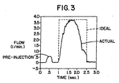
- the graph of Figure 3 shows an ideal fuel injection rate for a fuel injector.
- the fuel curve should ideally be square so that the combustion chamber receives an optimal amount of fuel.
- Actual fuel injection curves have been found to be less than ideal, thereby contributing to the inefficiency of the engine. It is desirable to provide a high speed fuel injector that will supply a more optimum fuel curve than fuel injectors in the prior art.
- the poppet valve constantly strikes the valve seat during the fuel injection cycles of the injector. Eventually the seat and the poppet valve will wear, so that the valve is not properly seated within the valve chamber. Improper valve seating may result in an early release of the working fluid into the intensifier chamber, causing the injector to prematurely inject fuel into the combustion chamber. It would be desirable to provide an injector valve that did not create wear between the working fluid control valve and the associated valve seat of the injector.
- the present invention is a fuel injector which has a double solenoid three-way or four-way spool valve that controls the flow of a working fluid that is used to move an intensifier piston of the injector.
- the fuel injector includes a nozzle which is in fluid communication with a fuel port through a pressure chamber.
- the pressure chamber contains an intensifier piston which can move to decrease the volume of the chamber and increase the pressure of the fuel.
- the pressurized fuel is discharged into the combustion chamber of an engine through the nozzle of the injector.
- the spool valve is moved by a pair of solenoids between a first position and a second position. Movement of the spool valve provides fluid communication between the intensifier piston and the working fluid ports of the injector, so that the working fluid strokes the intensifier piston. It has been found that the solenoid control valve of the present invention is very responsive and provides a more optimal fuel curve than injectors in the prior art. Additionally, the spool valve moves between bearing surfaces of a valve housing that are separate from the valve seats of the working fluid ports, thereby reducing wear on the seats and insuring a repeatable operation of the control valve.
- Figures 4 and 5 show a fuel injector 50 of the present invention.
- the fuel injector 50 is typically mounted to an engine block and injects a controlled pressurized volume of fuel into a combustion chamber (not shown).
- the injector 50 of the present invention is typically used to inject diesel fuel into a compression ignition engine, although it is to be understood that the injector could also be used in a spark ignition engine or any other system that requires the injection of a fluid.
- the fuel injector 10 has an injector housing 52 that is typically constructed from a plurality of individual parts.
- the housing 52 includes an outer casing 54 that contains block members 56, 58, and 60.
- the outer casing 54 has a fuel port 64 that is coupled to a fuel pressure chamber 66 by a fuel passage 68.
- a first check valve 70 is located within fuel passage 68 to prevent a reverse flow of fuel from the pressure chamber 66 to the fuel port 64.
- the pressure chamber 26 is coupled to a nozzle 72 through fuel passage 74.
- a second check valve 76 is located within the fuel passage 74 to prevent a reverse flow of fuel from the nozzle 72 to the pressure chamber 66.
- the flow of fuel through the nozzle 72 is controlled by a needle valve 78 that is biased into a closed position by spring 80 located within a spring chamber 81.
- the needle valve 78 has a shoulder 82 above the location where the passage 74 enters the nozzle 78. When fuel flows into the passage 74 the pressure of the fuel applies a force on the shoulder 82. The shoulder force lifts the needle valve 78 away from the nozzle openings 72 and allows fuel to be discharged from the injector 50.
- a passage 83 may be provided between the spring chamber 81 and the fuel passage 68 to drain any fuel that leaks into the chamber 81.
- the drain passage 83 prevents the build up of a hydrostatic pressure within the chamber 81 which could create a counteractive force on the needle valve 78 and degrade the performance of the injector 10.
- the volume of the pressure chamber 66 is varied by an intensifier piston 84.
- the intensifier piston 84 extends through a bore 86 of block 60 and into a first intensifier chamber 88 located within an upper valve block 90.
- the piston 84 includes a shaft member 92 which has a shoulder 94 that is attached to a head member 96.
- the shoulder 94 is retained in position by clamp 98 that fits within a corresponding groove 100 in the head member 96.
- the head member 96 has a cavity which defines a second intensifier chamber 102.
- the first intensifier chamber 88 is in fluid communication with a first intensifier passage 104 that extends through block 90.
- the second intensifier chamber 102 is in fluid communication with a second intensifier passage 106.
- the block 90 also has a supply working passage 108 that is in fluid communication with a supply working port 110.
- the supply port is typically coupled to a system that supplies a working fluid which is used to control the movement of the intensifier piston 84.
- the working fluid is typically a hydraulic fluid that circulates in a closed system separate from the fuel. Alternatively the fuel could also be used as the working fluid.
- Both the outer body 54 and block 90 have a number of outer grooves 112 which typically retain O-rings (not shown) that seal the injector 10 against the engine block. Additionally, block 62 and outer shell 54 may be sealed to block 90 by O-ring 114.
- Block 60 has a passage 116 that is in fluid communication with the fuel port 64.
- the passage 116 allows any fuel that leaks from the pressure chamber 66 between the block 62 and piston 84 to be drained back into the fuel port 64.
- the passage 116 prevents fuel from leaking into the first intensifier chamber 88.
- the flow of working fluid into the intensifier chambers 88 and 102 can be controlled by a four-way solenoid control valve 118.
- the control valve 118 has a spool 120 that moves within a valve housing 122.
- the valve housing 122 has openings connected to the passages 104, 106 and 108 and a drain port 124.
- the spool 120 has an inner chamber 126 and a pair of spool ports that can be coupled to the drain ports 124.
- the spool 120 also has an outer groove 132.
- the ends of the spool 120 have openings 134 which provide fluid communication between the inner chamber 126 and the valve chamber 134 of the housing 122. The openings 134 maintain the hydrostatic balance of the spool 120.
- the valve spool 120 is moved between the first position shown in Fig. 4 and a second position shown in Fig. 5, by a first solenoid 138 and a second solenoid 140.
- the solenoids 138 and 140 are typically coupled to a controller which controls the operation of the injector.
- the first solenoid 138 When the first solenoid 138 is energized, the spool 120 is pulled to the first position, wherein the first groove 132 allows the working fluid to flow from the supply working passage 108 into the first intensifier chamber 88, and the fluid flows from the second intensifier chamber 102 into the inner chamber 126 and out the drain port 124.
- the spool 120 When the second solenoid 140 is energized the spool 120 is pulled to the second position, wherein the first groove 132 provides fluid communication between the supply working passage 108 and the second intensifier chamber 102, and between the first intensifier chamber 88 and the drain port 124.
- the groove 132 and passages 128 are preferably constructed so that the initial port is closed before the final port is opened. For example, when the spool 120 moves from the first position to the second position, the portion of the spool adjacent to the groove 132 initially blocks the first passage 104 before the passage 128 provides fluid communication between the first passage 104 and the drain port 124. Delaying the exposure of the ports, reduces the pressure surges in the system and provides an injector which has more predictable firing points on the fuel injection curve.
- the spool 120 typically engages a pair of bearing surfaces 142 in the valve housing 122.
- Both the spool 120 and the housing 122 are preferably constructed from a magnetic material such as a hardened 52100 or 440c steel, so that the hystersis of the material will maintain the spool 120 in either the first or second position.
- the hystersis allows the solenoids to be de-energized after the spool 120 is pulled into position.
- the control valve operates in a digital manner, wherein the spool 120 is moved by a defined pulse that is provided to the appropriate solenoid. Operating the valve in a digital manner reduces the heat generated by the coils and increases the reliability and life of the injector.
- the first solenoid 138 is energized and pulls the spool 120 to the first position, so that the working fluid flows from the supply port 110 into the first intensifier chamber 88 and from the second intensifier chamber 102 into the drain port 124.
- the flow of working fluid into the intensifer chamber 88 moves the piston 84 and increases the volume of chamber 66.
- the increase in the chamber 66 volume decreases the chamber pressure and draws fuel into the chamber 66 from the fuel port 64.
- Power to the first solenoid 138 is terminated when the spool 120 reaches the first position.
- the second solenoid 140 When the chamber 66 is filled with fuel, the second solenoid 140 is energized to pull the spool 120 into the second position. Power to the second solenoid 140 is terminated when the spool reaches the second position. The movement of the spool 120 allows working fluid to flow into the second intensifier chamber 102 from the supply port 110 and from the first intensifier chamber 88 into the drain port 124.
- the head 96 of the intensifier piston 96 has an area much larger than the end of the piston 84, so that the pressure of the working fluid generates a force that pushes the intensifier piston 84 and reduces the volume of the pressure chamber 66.
- the stroking cycle of the intensifier piston 84 increases the pressure of the fuel within the pressure chamber 66.
- the pressurized fuel is discharged from the injector through the nozzle 72.
- the fuel is typically introduced to the injector at a pressure between 1000-2000 psi.
- the piston has a head to end ratio of approximately 10:1, wherein the pressure of the fuel discharged by the injector is between 10,000-20,000 psi.
- the double solenoid spool valve of the present invention provide a fuel injector which can more precisely discharge fuel into the combustion chamber of the engine than injectors of the prior art.
- the increase in accuracy provides a fuel injector that more closely approximates the square fuel curve shown in the graph of Fig. 3.
- the high speed solenoid control valves can also accurately supply the pre-discharge of fuel shown in the graph.
- Figure 6 shows an alternate embodiment of a fuel injector of the present invention which does not have a return spring for the needle valve.
- the supply working passage 108 is coupled to a nozzle return chamber 150 by passage 152.
- the needle valve 78 is biased into the closed position by the pressure of the working fluid in the return chamber 150.
- the intensifier piston 84 is stroked, the pressure of the fuel is much greater than the pressure of the working fluid, so that the fuel pressure pushes the needle valve 78 away from the nozzle openings 72.
- the intensifier piston 84 returns to the original position, the pressure of the working fluid within the return chamber 150 moves the needle valve 78 and closes the nozzle 72.
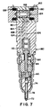
- Figure 7 shows an injector 160 controlled by a three-way control valve 162.
- the first passage 108 is connected to a drain port 164 in block 90, and the intensifier piston 84 has a return spring 166 which biases the piston 84 away from the needle valve 78. Movement of the spool 168 provides fluid communication between the second passage 106 and either the supply port 110 or the drain port 124.
- the second passage 106 When the spool 168 is in the second position, the second passage 106 is in fluid communication with the supply passage 108, wherein the pressure within the second intensifier chamber 102 pushes the intensifier piston 84 and pressurized fuel is ejected from the injector 160.
- the fluid within the first intensifier chamber 88 flows through the drain port 164 and the spring 166 is deflected to a compressed state.
- the second passage 106 is in fluid communication with the drain port 124 and the second intensifier chamber 102 no longer receives pressurized working fluid from the supply port 110.
- the force of the spring 166 moves the intensifier piston 84 back to the original position.
- the fluid within the second intensifier chamber 102 flows through the drain port 124.
- Both the three-way and four-way control valves have inner chambers 126 that are in fluid communication with the valve chamber 132 through spool openings 134, and the drain ports 124 through ports 130.
- the ports inner chamber and openings insure that any fluid pressure within the Valve chamber is applied equally to both ends of the spool.
- the equal fluid pressure balances the spool so that the solenoids do not have to overcome the fluid pressure within the valve chamber when moving between positions. Hydrostatic pressure will counteract the pull of the solenoids, thereby requiring more current for the solenoids to switch the valve.
- the solenoids of the present control valve thus have lower power requirements and generate less heat than injectors of the prior art, which must supply additional power to overcome any hydrostatic pressure within the valve.
- the balanced spool also provides a control valve that has a faster response time, thereby increasing the duration interval of the maximum amount of fuel emitted by the injector. Increasing the maximum fuel duration time provides a fuel injection curve that is more square and more approximates an ideal curve.
- the ends of the spool 120 may have concave surfaces 170 that extend from an outer rim to openings 134 in the spool 120.
- the concave surfaces 170 function as a reservoir that collects any working fluid that leaks into the gaps between the valve housing 122 and the end of the spool.
- the concave surfaces significantly reduce any hydrostatic pressure that may build up at the ends of the spool 120.
- the annular rim at the ends of the spool 120 should have an area sufficient to provide enough hysteris between the spool and housing to maintain the spool in position after the solenoid has been de-energized.
Abstract
Description
- The present invention relates to a fuel injector for an internal combustion engine.
- Fuel injectors are used to introduce pressurized fuel into the combustion chamber of an internal combustion engine. Figure 1 shows a
fuel injection system 10 of the prior art. The injection system includes anozzle 12 that is coupled to afuel port 14 through anintensifier chamber 16. Theintensifier chamber 16 contains anintensifier piston 18 which reduces the volume of thechamber 16 and increases the pressure of the fuel therein. The pressurized fuel is released into a combustion chamber through thenozzle 12. - The
intensifier piston 18 is stroked by a working fluid that is controlled by apoppet valve 20. The working fluid enters the valve throughport 22. Thepoppet valve 20 is coupled to asolenoid 24 which can be energized to pull the valve into an open position. As shown in Figure 2, when thesolenoid 24 opens thepoppet valve 20, the working fluid applies a pressure to theintensifier piston 18. The pressure of the working fluid moves thepiston 18 and pressurizes the fuel. When thesolenoid 24 is deenergized,springs poppet valve 20 and theintensifier piston 18 back to the original positions. - Spring return fuel injectors are relatively slow because of the slow response time of the poppet valve return spring. Additionally, the spring rate of the spring generates an additional force which must be overcome by the solenoid. Consequently the solenoid must be provided with enough current to overcome the spring force and the inertia of the valve. Higher currents generate additional heat and degrade the life and performance of the solenoid. Furthermore, the spring rate of the springs may change because of creep and fatigue. The change in spring rate will create varying results over the life of the injector.
- Conventional fuel injectors typically incorporate a mechanical feature which determines the shape of the fuel curve. Mechanical rate shapers are relatively inaccurate and are susceptible to wear and fatigue. Additionally, fuel leakage into the spring chambers of the nozzle and the intensifier may create a hydrostatic pressure that will degrade the performance of the valve.
- The graph of Figure 3 shows an ideal fuel injection rate for a fuel injector. To improve the efficiency of the engine, it is desirable to pre-inject fuel into the combustion chamber before the main discharge of fuel. As shown in phantom, the fuel curve should ideally be square so that the combustion chamber receives an optimal amount of fuel. Actual fuel injection curves have been found to be less than ideal, thereby contributing to the inefficiency of the engine. It is desirable to provide a high speed fuel injector that will supply a more optimum fuel curve than fuel injectors in the prior art.
- As shown in Figs. 1 and 2, the poppet valve constantly strikes the valve seat during the fuel injection cycles of the injector. Eventually the seat and the poppet valve will wear, so that the valve is not properly seated within the valve chamber. Improper valve seating may result in an early release of the working fluid into the intensifier chamber, causing the injector to prematurely inject fuel into the combustion chamber. It would be desirable to provide an injector valve that did not create wear between the working fluid control valve and the associated valve seat of the injector.
- The present invention is a fuel injector which has a double solenoid three-way or four-way spool valve that controls the flow of a working fluid that is used to move an intensifier piston of the injector. The fuel injector includes a nozzle which is in fluid communication with a fuel port through a pressure chamber. The pressure chamber contains an intensifier piston which can move to decrease the volume of the chamber and increase the pressure of the fuel. The pressurized fuel is discharged into the combustion chamber of an engine through the nozzle of the injector.
- The spool valve is moved by a pair of solenoids between a first position and a second position. Movement of the spool valve provides fluid communication between the intensifier piston and the working fluid ports of the injector, so that the working fluid strokes the intensifier piston. It has been found that the solenoid control valve of the present invention is very responsive and provides a more optimal fuel curve than injectors in the prior art. Additionally, the spool valve moves between bearing surfaces of a valve housing that are separate from the valve seats of the working fluid ports, thereby reducing wear on the seats and insuring a repeatable operation of the control valve.
- The objects and advantages of the present invention will become more readily apparent to those ordinarily skilled in the art after reviewing the following detailed description and accompanying drawings, wherein:
- Figure 1 is a cross-sectional view of a fuel injector of the prior art;
- Figure 2 is a cross-sectional view similar to Fig. 1, showing the fuel injector injecting fuel;
- Figure 3 is a graph showing the ideal and actual fuel injection curves for a fuel injector;
- Figure 4 is a cross-sectional view of a fuel injector with a four-way control valve that has a spool valve in a first position;
- Figure 5 is a cross-sectional view of the fuel injector with the spool valve in a second position;
- Figure 6 is an alternate embodiment of the fuel . injector of Fig. 4;
- Figure 7 is a cross-sectional view of an alternate embodiment of a fuel injector which has a three-way control valve.
-
- Referring to the drawings more particularly by reference numbers, Figures 4 and 5 show a
fuel injector 50 of the present invention. Thefuel injector 50 is typically mounted to an engine block and injects a controlled pressurized volume of fuel into a combustion chamber (not shown). Theinjector 50 of the present invention is typically used to inject diesel fuel into a compression ignition engine, although it is to be understood that the injector could also be used in a spark ignition engine or any other system that requires the injection of a fluid. - The
fuel injector 10 has aninjector housing 52 that is typically constructed from a plurality of individual parts. Thehousing 52 includes anouter casing 54 that containsblock members outer casing 54 has afuel port 64 that is coupled to afuel pressure chamber 66 by afuel passage 68. Afirst check valve 70 is located withinfuel passage 68 to prevent a reverse flow of fuel from thepressure chamber 66 to thefuel port 64. Thepressure chamber 26 is coupled to anozzle 72 throughfuel passage 74. Asecond check valve 76 is located within thefuel passage 74 to prevent a reverse flow of fuel from thenozzle 72 to thepressure chamber 66. - The flow of fuel through the
nozzle 72 is controlled by aneedle valve 78 that is biased into a closed position byspring 80 located within a spring chamber 81. Theneedle valve 78 has ashoulder 82 above the location where thepassage 74 enters thenozzle 78. When fuel flows into thepassage 74 the pressure of the fuel applies a force on theshoulder 82. The shoulder force lifts theneedle valve 78 away from thenozzle openings 72 and allows fuel to be discharged from theinjector 50. - A
passage 83 may be provided between the spring chamber 81 and thefuel passage 68 to drain any fuel that leaks into the chamber 81. Thedrain passage 83 prevents the build up of a hydrostatic pressure within the chamber 81 which could create a counteractive force on theneedle valve 78 and degrade the performance of theinjector 10. - The volume of the
pressure chamber 66 is varied by anintensifier piston 84. Theintensifier piston 84 extends through abore 86 ofblock 60 and into afirst intensifier chamber 88 located within anupper valve block 90. Thepiston 84 includes ashaft member 92 which has ashoulder 94 that is attached to ahead member 96. Theshoulder 94 is retained in position byclamp 98 that fits within a correspondinggroove 100 in thehead member 96. Thehead member 96 has a cavity which defines asecond intensifier chamber 102. - The
first intensifier chamber 88 is in fluid communication with afirst intensifier passage 104 that extends throughblock 90. Likewise, thesecond intensifier chamber 102 is in fluid communication with asecond intensifier passage 106. - The
block 90 also has asupply working passage 108 that is in fluid communication with asupply working port 110. The supply port is typically coupled to a system that supplies a working fluid which is used to control the movement of theintensifier piston 84. The working fluid is typically a hydraulic fluid that circulates in a closed system separate from the fuel. Alternatively the fuel could also be used as the working fluid. Both theouter body 54 and block 90 have a number ofouter grooves 112 which typically retain O-rings (not shown) that seal theinjector 10 against the engine block. Additionally, block 62 andouter shell 54 may be sealed to block 90 by O-ring 114. -
Block 60 has apassage 116 that is in fluid communication with thefuel port 64. Thepassage 116 allows any fuel that leaks from thepressure chamber 66 between theblock 62 andpiston 84 to be drained back into thefuel port 64. Thepassage 116 prevents fuel from leaking into thefirst intensifier chamber 88. - The flow of working fluid into the
intensifier chambers solenoid control valve 118. Thecontrol valve 118 has aspool 120 that moves within avalve housing 122. Thevalve housing 122 has openings connected to thepassages drain port 124. Thespool 120 has aninner chamber 126 and a pair of spool ports that can be coupled to thedrain ports 124. Thespool 120 also has anouter groove 132. The ends of thespool 120 haveopenings 134 which provide fluid communication between theinner chamber 126 and thevalve chamber 134 of thehousing 122. Theopenings 134 maintain the hydrostatic balance of thespool 120. - The
valve spool 120 is moved between the first position shown in Fig. 4 and a second position shown in Fig. 5, by afirst solenoid 138 and asecond solenoid 140. Thesolenoids first solenoid 138 is energized, thespool 120 is pulled to the first position, wherein thefirst groove 132 allows the working fluid to flow from thesupply working passage 108 into thefirst intensifier chamber 88, and the fluid flows from thesecond intensifier chamber 102 into theinner chamber 126 and out thedrain port 124. When thesecond solenoid 140 is energized thespool 120 is pulled to the second position, wherein thefirst groove 132 provides fluid communication between thesupply working passage 108 and thesecond intensifier chamber 102, and between thefirst intensifier chamber 88 and thedrain port 124. - The
groove 132 andpassages 128 are preferably constructed so that the initial port is closed before the final port is opened. For example, when thespool 120 moves from the first position to the second position, the portion of the spool adjacent to thegroove 132 initially blocks thefirst passage 104 before thepassage 128 provides fluid communication between thefirst passage 104 and thedrain port 124. Delaying the exposure of the ports, reduces the pressure surges in the system and provides an injector which has more predictable firing points on the fuel injection curve. - The
spool 120 typically engages a pair of bearingsurfaces 142 in thevalve housing 122. Both thespool 120 and thehousing 122 are preferably constructed from a magnetic material such as a hardened 52100 or 440c steel, so that the hystersis of the material will maintain thespool 120 in either the first or second position. The hystersis allows the solenoids to be de-energized after thespool 120 is pulled into position. In this respect the control valve operates in a digital manner, wherein thespool 120 is moved by a defined pulse that is provided to the appropriate solenoid. Operating the valve in a digital manner reduces the heat generated by the coils and increases the reliability and life of the injector. - In operation, the
first solenoid 138 is energized and pulls thespool 120 to the first position, so that the working fluid flows from thesupply port 110 into thefirst intensifier chamber 88 and from thesecond intensifier chamber 102 into thedrain port 124. The flow of working fluid into theintensifer chamber 88 moves thepiston 84 and increases the volume ofchamber 66. The increase in thechamber 66 volume decreases the chamber pressure and draws fuel into thechamber 66 from thefuel port 64. Power to thefirst solenoid 138 is terminated when thespool 120 reaches the first position. - When the
chamber 66 is filled with fuel, thesecond solenoid 140 is energized to pull thespool 120 into the second position. Power to thesecond solenoid 140 is terminated when the spool reaches the second position. The movement of thespool 120 allows working fluid to flow into thesecond intensifier chamber 102 from thesupply port 110 and from thefirst intensifier chamber 88 into thedrain port 124. - The
head 96 of theintensifier piston 96 has an area much larger than the end of thepiston 84, so that the pressure of the working fluid generates a force that pushes theintensifier piston 84 and reduces the volume of thepressure chamber 66. The stroking cycle of theintensifier piston 84 increases the pressure of the fuel within thepressure chamber 66. The pressurized fuel is discharged from the injector through thenozzle 72. The fuel is typically introduced to the injector at a pressure between 1000-2000 psi. In the preferred embodiment, the piston has a head to end ratio of approximately 10:1, wherein the pressure of the fuel discharged by the injector is between 10,000-20,000 psi. - After the fuel is discharged from the injector the
first solenoid 138 is again energized to pull thespool 120 to the first position and the cycle is repeated. It has been found that the double solenoid spool valve of the present invention provide a fuel injector which can more precisely discharge fuel into the combustion chamber of the engine than injectors of the prior art. The increase in accuracy provides a fuel injector that more closely approximates the square fuel curve shown in the graph of Fig. 3. The high speed solenoid control valves can also accurately supply the pre-discharge of fuel shown in the graph. - Figure 6 shows an alternate embodiment of a fuel injector of the present invention which does not have a return spring for the needle valve. In this embodiment the
supply working passage 108 is coupled to anozzle return chamber 150 bypassage 152. Theneedle valve 78 is biased into the closed position by the pressure of the working fluid in thereturn chamber 150. When theintensifier piston 84 is stroked, the pressure of the fuel is much greater than the pressure of the working fluid, so that the fuel pressure pushes theneedle valve 78 away from thenozzle openings 72. When theintensifier piston 84 returns to the original position, the pressure of the working fluid within thereturn chamber 150 moves theneedle valve 78 and closes thenozzle 72. - Figure 7 shows an
injector 160 controlled by a three-way control valve 162. In this embodiment, thefirst passage 108 is connected to adrain port 164 inblock 90, and theintensifier piston 84 has areturn spring 166 which biases thepiston 84 away from theneedle valve 78. Movement of thespool 168 provides fluid communication between thesecond passage 106 and either thesupply port 110 or thedrain port 124. - When the
spool 168 is in the second position, thesecond passage 106 is in fluid communication with thesupply passage 108, wherein the pressure within thesecond intensifier chamber 102 pushes theintensifier piston 84 and pressurized fuel is ejected from theinjector 160. The fluid within thefirst intensifier chamber 88 flows through thedrain port 164 and thespring 166 is deflected to a compressed state. When thespool 168 is pulled by thefirst solenoid 138 back to the first position, thesecond passage 106 is in fluid communication with thedrain port 124 and thesecond intensifier chamber 102 no longer receives pressurized working fluid from thesupply port 110. The force of thespring 166 moves theintensifier piston 84 back to the original position. The fluid within thesecond intensifier chamber 102 flows through thedrain port 124. - Both the three-way and four-way control valves have
inner chambers 126 that are in fluid communication with thevalve chamber 132 throughspool openings 134, and thedrain ports 124 throughports 130. The ports inner chamber and openings insure that any fluid pressure within the Valve chamber is applied equally to both ends of the spool. The equal fluid pressure balances the spool so that the solenoids do not have to overcome the fluid pressure within the valve chamber when moving between positions. Hydrostatic pressure will counteract the pull of the solenoids, thereby requiring more current for the solenoids to switch the valve. The solenoids of the present control valve thus have lower power requirements and generate less heat than injectors of the prior art, which must supply additional power to overcome any hydrostatic pressure within the valve. The balanced spool also provides a control valve that has a faster response time, thereby increasing the duration interval of the maximum amount of fuel emitted by the injector. Increasing the maximum fuel duration time provides a fuel injection curve that is more square and more approximates an ideal curve. - As shown in Fig. 4, the ends of the
spool 120 may haveconcave surfaces 170 that extend from an outer rim toopenings 134 in thespool 120. Theconcave surfaces 170 function as a reservoir that collects any working fluid that leaks into the gaps between thevalve housing 122 and the end of the spool. The concave surfaces significantly reduce any hydrostatic pressure that may build up at the ends of thespool 120. The annular rim at the ends of thespool 120 should have an area sufficient to provide enough hysteris between the spool and housing to maintain the spool in position after the solenoid has been de-energized. - While certain exemplary embodiments have been described and shown in the accompanying drawings, it is to be understood that such embodiments are merely illustrative of and not restrictive on the broad invention, and that this invention not be limited to the specific constructions and arrangements shown and described, since various other modifications may occur to those ordinarily skilled in the art.
Claims (28)
- An upper fuel injector unit coupled to a lower fuel injector unit that has a nozzle coupled to a fuel port that receives a fuel, comprising:a housing that has a supply working port and a return working port for receiving and releasing a working fluid;an intensifier that moves from a return position and a power position, wherein said intensifier increases a fuel pressure to the nozzle when in the power position, said intensifier being adjacent to a first intensifier chamber and a second intensifier chamber;a spool that moves between a first position and a second position, said spool being operatively connected to said working fluid ports and said intensifier chambers so that said first intensifier chamber is in fluid communication with said supply working port and said second intensifier chamber is in fluid communication with said return working port when said spool is in said first position, wherein said first intensifier chamber is pressurized and said intensifier moves to the return position, and said first intensifier chamber is in fluid communication with said return working port and said second intensifier chamber is in fluid communication with said supply working port when said spool is in said second position, wherein said second intensifier chamber is pressurized and said intensifier moves to the power position; and,solenoid means for moving said spool between said first position and said second position.
- The upper fuel unit injector unit as recited in claim 1, wherein said solenoid means includes a first solenoid that moves said spool from said second position to said first position, and a second solenoid that moves said spool from said second position to said first position.
- The upper fuel unit injector as recited in claim 1, wherein the working fluid is also the fuel.
- The upper fuel unit injector as recited in claim 1, wherein said housing has a supply working passage between said supply working port and said spool, a return working passage between said return working port and said spool, a first intensifier passage between said first intensifier chamber and said spool valve and a second intensifier passage between said second intensifier chamber and said spool, said spool having a first groove that provides fluid communication between said supply working passage and said first intensifier passage when said spool is in said first position and fluid communication between said supply working passage and said second intensifier passage when said spool is in said second position, said spool also having a pair of passages and an internal chamber that provide fluid communication between said second intensifier passage and said return working passage when said spool is in said first position, and fluid communication between said first intensifier passage and said return working passage when said spool is in said second position.
- The upper fuel injector unit as recited in claim 1, further comprising a valve housing which has a pair of bearing surfaces, said spool being cylindrical in shape with a pair opposite ends that engage said bearing surface and an outer longitudinal wall between said ends which contain the groove and the passages.
- The upper fuel injector unit as recited in claim 5, wherein said valve housing and said spool are constructed from a steel.
- The upper fuel injector unit as recited in claim 4, wherein said spool moves within a valve chamber of a valve housing, said spool having a pair of opening that provide fluid communication between said inner chamber and said valve chamber.
- A fuel injector, comprising:a housing that has a fuel port for receiving a fuel, a supply working port and a return working port for receiving and releasing a working fluid, said housing further having a supply working passage between said supply working port and said spool valve, a return working passage in fluid communication with said return working port, a first intensifier passage in fluid communication with said first intensifier chamber and a second intensifier passage in fluid communication with said second intensifier chamber;a nozzle that discharges the fuel from said housing;an intensifier that moves from a return position and a power position, wherein said intensifier increases a fuel pressure to the nozzle when in the power position, said intensifier being adjacent to a first intensifier chamber and a second intensifier chamber;a spool that moves between a first position and a second position, said spool having a first groove that provides fluid communication between said supply working passage and said first intensifier passage when said spool valve is in said first position and fluid communication between said supply working passage and said second intensifier passage when said spool is in said second position, said spool also having a pair of passages and an internal chamber that provide fluid communication between said second intensifier passage and said return working passage when said spool is in said first position, and fluid communication between said first intensifier passage and said return working passage when said spool is in said second position, wherein said first intensifier chamber is pressurized and said intensifier moves to the return position when said spool is in the first position and said second intensifier chamber is pressurized and said intensifier moves to the power position when said spool is in the second position;a first solenoid operatively connected to said spool to move said spool from said second position to said first position; and,a second solenoid operatively connected to said spool valve to move said spool from said first position to said second position.
- The fuel injector as recited in claim 8, further comprising a valve housing which has a pair of bearing surfaces, said spool being cylindrical in shape with a pair opposite ends that engage said bearing surface and an outer longitudinal wall between said ends which contain the groove and the passages.
- The fuel injector as recited in claim 8, wherein said spool moves within a valve chamber of a valve housing, said spool having a pair of opening that provide fluid communication between said inner chamber and said valve chamber.
- The fuel injector as recited in claim 8, wherein said housing has a passage that provides fluid communication between said fuel port and a spring chamber which houses a spring that biases said nozzle.
- The fuel injector as recited in claim 8, wherein said housing has a passage that provides fluid communication between said supply working passage and a nozzle return chamber.
- The fuel injector as recited in claim 9, wherein said valve housing and said spool are constructed from a magnetic steel.
- The fuel injector as recited in claim 8, wherein the working fluid is also the fuel.
- An upper fuel injector unit coupled to a lower fuel injector unit that has a nozzle coupled to a fuel port that receives a fuel, comprising:a housing that has a supply working port and a return working port for receiving and releasing a working fluid;an intensifier that moves from a return position and a power position, wherein said intensifier increases a fuel pressure to the nozzle when in the power position, said intensifier being adjacent to a spring chamber and an intensifier chamber, said spring chamber being in fluid communication with said return working port;a spring within said spring chamber, said spring biases said intensifier to the return position;a spool that moves between a first position and a second position, said spool being operatively connected to said working fluid ports and said intensifier chambers so that intensifier chamber is in fluid communication with said return working port when said spool is in said first position, wherein said spring moves said intensifier to the return position, and said intensifier chamber is in fluid communication with said supply working port when said spool is in said second position, wherein said second intensifier chamber is pressurized and said intensifier moves to the power position; and,solenoid means for moving said spool between said first position and said second position.
- The upper fuel injector unit as recited in claim 15, wherein said solenoid means includes a first solenoid that moves said spool from said second position to said first position, and a second solenoid that moves said spool from said second position to said first position.
- The upper fuel injector unit as recited in claim 15, wherein the working fluid is also the fuel.
- The upper fuel injector unit as recited in claim 15, wherein said housing has a supply working passage connected to said supply working port and said spool, a return working passage connected to said return working port and said spool, a first intensifier passage connected to said spring chamber and said return working port and a second intensifier passage connected to said second intensifier chamber and said spool, said spool having a groove that provides fluid communication between said supply working passage and said intensifier passage when said spool is in said first position and fluid communication between said intensifier passage and said return working passage when said spool is in said second position.
- The upper fuel injector unit as recited in claim 15, further comprising a valve housing which has a pair of bearing surfaces, said spool being cylindrical in shape with a pair opposite ends that engage said bearing surface and an outer longitudinal wall between said ends which contain the groove and the passages.
- The upper fuel injector unit as recited in claim 19, wherein said valve housing and said spool are constructed from a magnetic steel.
- The upper fuel injector unit as recited in claim 18, wherein said spool moves within a valve chamber of a valve housing, said spool having a pair of opening that provide fluid communication between said inner chamber and said valve chamber.
- A fuel injector, comprising:a housing that has a fuel port for receiving a fuel, a supply working port and a return working port for receiving and releasing a working fluid, said housing further having a supply working passage between said supply working port and said spool valve, a return working passage in fluid communication with said return working port, a first intensifier passage in fluid communication with said first intensifier chamber and a second intensifier passage in fluid communication with said second intensifier chamber;a nozzle that discharges the fuel from said housing;an intensifier that moves from a return position and a power position, wherein said intensifier increases a fuel pressure to the nozzle when in the power position, said intensifier being adjacent to a spring chamber and an intensifier chamber, said spring chamber being in fluid communication with said return working port;a spring within said spring chamber, said spring biases said intensifier to the return position;a spool that moves between a first position and a second position, said spool having a groove that provides fluid communication between said return working passage and said intensifier passage when said spool valve is in said first position, wherein said spring moves said intensifier to the return position, and said intensifier chamber is in fluid communication with said supply working port when said spool is in said second position, wherein said intensifier chamber is pressurized and said intensifier moves to the power position when said spool;a first solenoid operatively connected to said spool to move said spool from said second position to said first position; and,a second solenoid operatively connected to said spool valve to move said spool from said first position to said second position.
- The fuel injector as recited in claim 22, further comprising a valve housing which has a pair of bearing surfaces, said spool being cylindrical in shape with a pair opposite ends that engage said bearing surface and an outer longitudinal wall between said ends which contain the groove and the passages.
- The fuel injector as recited in claim 22, wherein said spool moves within a valve chamber of a valve housing, said spool having a pair of opening that provide fluid communication between said inner chamber and said valve chamber.
- The fuel injector as recited in claim 22, wherein said housing has a passage that provides fluid communication between said fuel port and a spring chamber which houses a spring that biases said nozzle.
- The fuel injector as recited in claim 22, wherein said housing has a passage that provides fluid communication between said supply working passage and a nozzle return chamber.
- The fuel injector as recited in claim 23, wherein said valve housing and said spool are constructed from a magnetic steel.
- The fuel injector as recited in claim 22, wherein the working fluid is also the fuel.
Applications Claiming Priority (1)
| Application Number | Priority Date | Filing Date | Title |
|---|---|---|---|
| EP95925466A EP0835376B1 (en) | 1995-06-30 | 1995-06-30 | High speed fuel injector |
Related Parent Applications (1)
| Application Number | Title | Priority Date | Filing Date |
|---|---|---|---|
| EP95925466A Division EP0835376B1 (en) | 1995-06-30 | 1995-06-30 | High speed fuel injector |
Publications (1)
| Publication Number | Publication Date |
|---|---|
| EP1452726A1 true EP1452726A1 (en) | 2004-09-01 |
Family
ID=32749081
Family Applications (1)
| Application Number | Title | Priority Date | Filing Date |
|---|---|---|---|
| EP04002380A Withdrawn EP1452726A1 (en) | 1995-06-30 | 1995-06-30 | High speed fuel injector |
Country Status (1)
| Country | Link |
|---|---|
| EP (1) | EP1452726A1 (en) |
Cited By (1)
| Publication number | Priority date | Publication date | Assignee | Title |
|---|---|---|---|---|
| EP3919734A1 (en) * | 2020-06-02 | 2021-12-08 | Pratt & Whitney Canada Corp. | Fuel injection system for aircraft engine |
Citations (7)
| Publication number | Priority date | Publication date | Assignee | Title |
|---|---|---|---|---|
| US2967545A (en) * | 1957-07-01 | 1961-01-10 | Schmidt Franz Josef | Magnetically actuated slide valves |
| US4182492A (en) * | 1978-01-16 | 1980-01-08 | Combustion Research & Technology, Inc. | Hydraulically operated pressure amplification system for fuel injectors |
| US4279385A (en) * | 1978-02-11 | 1981-07-21 | Robert Bosch Gmbh | High pressure fuel injection apparatus for internal combustion engines |
| US4392612A (en) * | 1982-02-19 | 1983-07-12 | General Motors Corporation | Electromagnetic unit fuel injector |
| US4605166A (en) * | 1985-02-21 | 1986-08-12 | Stanadyne, Inc. | Accumulator injector |
| US4979674A (en) * | 1988-05-10 | 1990-12-25 | Diesel Kiki Co., Ltd. | Fuel injector |
| US5108070A (en) * | 1990-03-28 | 1992-04-28 | Mitsubishi Denki Kabushiki Kaisha | Flow control solenoid valve apparatus |
-
1995
- 1995-06-30 EP EP04002380A patent/EP1452726A1/en not_active Withdrawn
Patent Citations (7)
| Publication number | Priority date | Publication date | Assignee | Title |
|---|---|---|---|---|
| US2967545A (en) * | 1957-07-01 | 1961-01-10 | Schmidt Franz Josef | Magnetically actuated slide valves |
| US4182492A (en) * | 1978-01-16 | 1980-01-08 | Combustion Research & Technology, Inc. | Hydraulically operated pressure amplification system for fuel injectors |
| US4279385A (en) * | 1978-02-11 | 1981-07-21 | Robert Bosch Gmbh | High pressure fuel injection apparatus for internal combustion engines |
| US4392612A (en) * | 1982-02-19 | 1983-07-12 | General Motors Corporation | Electromagnetic unit fuel injector |
| US4605166A (en) * | 1985-02-21 | 1986-08-12 | Stanadyne, Inc. | Accumulator injector |
| US4979674A (en) * | 1988-05-10 | 1990-12-25 | Diesel Kiki Co., Ltd. | Fuel injector |
| US5108070A (en) * | 1990-03-28 | 1992-04-28 | Mitsubishi Denki Kabushiki Kaisha | Flow control solenoid valve apparatus |
Cited By (1)
| Publication number | Priority date | Publication date | Assignee | Title |
|---|---|---|---|---|
| EP3919734A1 (en) * | 2020-06-02 | 2021-12-08 | Pratt & Whitney Canada Corp. | Fuel injection system for aircraft engine |
Similar Documents
| Publication | Publication Date | Title |
|---|---|---|
| US5460329A (en) | High speed fuel injector | |
| US6257499B1 (en) | High speed fuel injector | |
| US6575126B2 (en) | Solenoid actuated engine valve for an internal combustion engine | |
| US6161770A (en) | Hydraulically driven springless fuel injector | |
| US5638781A (en) | Hydraulic actuator for an internal combustion engine | |
| US6868831B2 (en) | Fuel injector with controlled high pressure fuel passage | |
| EP1080303B1 (en) | Fuel injector having differential piston for pressurizing fuel | |
| US5485957A (en) | Fuel injector with an internal pump | |
| MXPA02002198A (en) | Fuel injector assembly and internal combustion engine including same. | |
| US6845926B2 (en) | Fuel injector with dual control valve | |
| JPH06241144A (en) | Fuel injection device for internal combustion engine | |
| US5651501A (en) | Fluid damping of a valve assembly | |
| JPH1089189A (en) | Valve assembly provided with combined seat parts and fuel injector using it | |
| EP0835376B1 (en) | High speed fuel injector | |
| EP0736686A1 (en) | Fuel injection pump control | |
| EP1452726A1 (en) | High speed fuel injector | |
| JPH06100297B2 (en) | Fluid control valve | |
| WO2004020813A1 (en) | Fuel injector having an expansion tank accumulator | |
| JPS6029830B2 (en) | Internal combustion engine fuel injection system | |
| JPH11515069A (en) | High speed fuel injector | |
| JPS6038049Y2 (en) | Pump nozzle for internal combustion engine | |
| JPS6143228A (en) | Electrohydraulic control device of internal-combustion engine |
Legal Events
| Date | Code | Title | Description |
|---|---|---|---|
| PUAI | Public reference made under article 153(3) epc to a published international application that has entered the european phase |
Free format text: ORIGINAL CODE: 0009012 |
|
| 17P | Request for examination filed |
Effective date: 20040207 |
|
| AC | Divisional application: reference to earlier application |
Ref document number: 0835376 Country of ref document: EP Kind code of ref document: P |
|
| AK | Designated contracting states |
Kind code of ref document: A1 Designated state(s): DE FR IT |
|
| AX | Request for extension of the european patent |
Extension state: AL LT LV MK |
|
| AKX | Designation fees paid |
Designated state(s): DE FR IT |
|
| 17Q | First examination report despatched |
Effective date: 20070306 |
|
| STAA | Information on the status of an ep patent application or granted ep patent |
Free format text: STATUS: THE APPLICATION IS DEEMED TO BE WITHDRAWN |
|
| 18D | Application deemed to be withdrawn |
Effective date: 20070717 |