EP1460932B1 - A minimally-invasive system and method for monitoring analyte levels - Google Patents
A minimally-invasive system and method for monitoring analyte levels Download PDFInfo
- Publication number
- EP1460932B1 EP1460932B1 EP02805953A EP02805953A EP1460932B1 EP 1460932 B1 EP1460932 B1 EP 1460932B1 EP 02805953 A EP02805953 A EP 02805953A EP 02805953 A EP02805953 A EP 02805953A EP 1460932 B1 EP1460932 B1 EP 1460932B1
- Authority
- EP
- European Patent Office
- Prior art keywords
- patient
- electrode
- active electrode
- active
- analyte
- Prior art date
- Legal status (The legal status is an assumption and is not a legal conclusion. Google has not performed a legal analysis and makes no representation as to the accuracy of the status listed.)
- Expired - Lifetime
Links
Images


Classifications
-
- A—HUMAN NECESSITIES
- A61—MEDICAL OR VETERINARY SCIENCE; HYGIENE
- A61B—DIAGNOSIS; SURGERY; IDENTIFICATION
- A61B5/00—Measuring for diagnostic purposes; Identification of persons
- A61B5/14—Devices for taking samples of blood ; Measuring characteristics of blood in vivo, e.g. gas concentration within the blood, pH-value of blood
- A61B5/1405—Devices for taking blood samples
-
- A—HUMAN NECESSITIES
- A61—MEDICAL OR VETERINARY SCIENCE; HYGIENE
- A61B—DIAGNOSIS; SURGERY; IDENTIFICATION
- A61B5/00—Measuring for diagnostic purposes; Identification of persons
- A61B5/145—Measuring characteristics of blood in vivo, e.g. gas concentration, pH value; Measuring characteristics of body fluids or tissues, e.g. interstitial fluid, cerebral tissue
- A61B5/1486—Measuring characteristics of blood in vivo, e.g. gas concentration, pH value; Measuring characteristics of body fluids or tissues, e.g. interstitial fluid, cerebral tissue using enzyme electrodes, e.g. with immobilised oxidase
- A61B5/14865—Measuring characteristics of blood in vivo, e.g. gas concentration, pH value; Measuring characteristics of body fluids or tissues, e.g. interstitial fluid, cerebral tissue using enzyme electrodes, e.g. with immobilised oxidase invasive, e.g. introduced into the body by a catheter or needle or using implanted sensors
-
- A—HUMAN NECESSITIES
- A61—MEDICAL OR VETERINARY SCIENCE; HYGIENE
- A61B—DIAGNOSIS; SURGERY; IDENTIFICATION
- A61B5/00—Measuring for diagnostic purposes; Identification of persons
- A61B5/145—Measuring characteristics of blood in vivo, e.g. gas concentration, pH value; Measuring characteristics of body fluids or tissues, e.g. interstitial fluid, cerebral tissue
- A61B5/14532—Measuring characteristics of blood in vivo, e.g. gas concentration, pH value; Measuring characteristics of body fluids or tissues, e.g. interstitial fluid, cerebral tissue for measuring glucose, e.g. by tissue impedance measurement
-
- A—HUMAN NECESSITIES
- A61—MEDICAL OR VETERINARY SCIENCE; HYGIENE
- A61B—DIAGNOSIS; SURGERY; IDENTIFICATION
- A61B5/00—Measuring for diagnostic purposes; Identification of persons
- A61B5/145—Measuring characteristics of blood in vivo, e.g. gas concentration, pH value; Measuring characteristics of body fluids or tissues, e.g. interstitial fluid, cerebral tissue
- A61B5/14546—Measuring characteristics of blood in vivo, e.g. gas concentration, pH value; Measuring characteristics of body fluids or tissues, e.g. interstitial fluid, cerebral tissue for measuring analytes not otherwise provided for, e.g. ions, cytochromes
-
- A—HUMAN NECESSITIES
- A61—MEDICAL OR VETERINARY SCIENCE; HYGIENE
- A61M—DEVICES FOR INTRODUCING MEDIA INTO, OR ONTO, THE BODY; DEVICES FOR TRANSDUCING BODY MEDIA OR FOR TAKING MEDIA FROM THE BODY; DEVICES FOR PRODUCING OR ENDING SLEEP OR STUPOR
- A61M5/00—Devices for bringing media into the body in a subcutaneous, intra-vascular or intramuscular way; Accessories therefor, e.g. filling or cleaning devices, arm-rests
- A61M5/14—Infusion devices, e.g. infusing by gravity; Blood infusion; Accessories therefor
- A61M5/158—Needles for infusions; Accessories therefor, e.g. for inserting infusion needles, or for holding them on the body
-
- A—HUMAN NECESSITIES
- A61—MEDICAL OR VETERINARY SCIENCE; HYGIENE
- A61M—DEVICES FOR INTRODUCING MEDIA INTO, OR ONTO, THE BODY; DEVICES FOR TRANSDUCING BODY MEDIA OR FOR TAKING MEDIA FROM THE BODY; DEVICES FOR PRODUCING OR ENDING SLEEP OR STUPOR
- A61M5/00—Devices for bringing media into the body in a subcutaneous, intra-vascular or intramuscular way; Accessories therefor, e.g. filling or cleaning devices, arm-rests
- A61M5/14—Infusion devices, e.g. infusing by gravity; Blood infusion; Accessories therefor
- A61M5/168—Means for controlling media flow to the body or for metering media to the body, e.g. drip meters, counters ; Monitoring media flow to the body
- A61M5/172—Means for controlling media flow to the body or for metering media to the body, e.g. drip meters, counters ; Monitoring media flow to the body electrical or electronic
- A61M5/1723—Means for controlling media flow to the body or for metering media to the body, e.g. drip meters, counters ; Monitoring media flow to the body electrical or electronic using feedback of body parameters, e.g. blood-sugar, pressure
-
- A—HUMAN NECESSITIES
- A61—MEDICAL OR VETERINARY SCIENCE; HYGIENE
- A61M—DEVICES FOR INTRODUCING MEDIA INTO, OR ONTO, THE BODY; DEVICES FOR TRANSDUCING BODY MEDIA OR FOR TAKING MEDIA FROM THE BODY; DEVICES FOR PRODUCING OR ENDING SLEEP OR STUPOR
- A61M5/00—Devices for bringing media into the body in a subcutaneous, intra-vascular or intramuscular way; Accessories therefor, e.g. filling or cleaning devices, arm-rests
- A61M5/14—Infusion devices, e.g. infusing by gravity; Blood infusion; Accessories therefor
- A61M5/158—Needles for infusions; Accessories therefor, e.g. for inserting infusion needles, or for holding them on the body
- A61M2005/1581—Right-angle needle-type devices
Definitions
- the present invention relates to a minimally-invasive system and method for monitoring analyte levels in a patient. More particularly, the present invention relates to a system and method employing a device which includes a micro probe functioning as an active electrode and a auxiliary electrode surrounding at least a portion of the active electrode, arranged to be placed against the skin of a patient to detect analyte levels in the patient with minimal pain and damage to the patient's skin.
- Some people having mild diabetes can regulate their blood glucose levels through diet. However, people having moderate or severe forms of diabetes must take insulin to sustain acceptable blood glucose levels.
- miniaturized glucose sensing needles have been developed over the past several years.
- These types of devices typically include a metal substrate with an enzyme as an active electrode and an adjacent metal substrate that serve as the return and reference electrodes.
- the enzyme typically glucose oxidase, catalyzes the oxidation of glucose, and the byproducts of the reaction are measured electrochemically at the active electrode.
- the electrochemical measurement is affected by imposing an electrical potential between the active and the counter/reference (auxiliary) electrodes. At a particular potential, electric current begins to flow as a consequence of the chemical reaction at the electrodes.
- the current is related to the concentration of the electro-active species, which is in turn governed by the amount of glucose in the test medium.
- the test medium is capillary blood; in the case of implantable electrodes, the medium is tissue.
- These devices are typically macroscopic or, in other words, more than 200 microns in diameter and often a centimeter or more in length. Accordingly, these devices are invasive, because they can penetrate the skin up to one centimeter deep. Additionally, these devices typically employ conventional needles, wires and multi-layer plastic substrates which require complicated multi-step manufacturing processes that are both time consuming and expensive. Examples of known glucose sensing devices are described in U.S. Patent Nos. 4,953,552 , 5,680,858 and 5,820,570 , and in PCT publication WO 98/46124 .
- the active electrode area increases the current response of the system. Especially in the case of the implantable system, the active electrode area is small - often ten-fold smaller than strip-based electrodes. Furthermore, the active and return/reference electrodes often share the same substrate - further limiting the available active area.
- One advantage of the invention described herein is that the return electrode is separated from the active electrode substrate and can be positioned on the surface of the skin, at least partially surrounding the minimally-invasive working electrode. This configuration allows maximum usage of the active electrode, and it permits the use of a large external return electrode. Both aspects improve the signal and performance of the system, while maintaining the small minimally invasive, pain-free format of the design.
- WO 96/14026 discloses a liquid delivery device comprising a housing having a lower surface for application to the skin of a subject and having a reservoir and a gas generation chamber therein separated by a displaceable membrane. Gas generated by an electrolytic cell under the control of a microprocessor causes the gas generation chamber to expand and the reservoir to contract, thereby discharging a liquid drug, such as insulin, from the reservoir via a hollow delivery needle extending from the lower surface.
- the delivery needle and a sensor needle both extend from the lower surface a sufficient distance so as to penetrate through the epidermis and into the dermis when the housing is pressed against the skin.
- the sensor needle has an enzymatic coating for the detection of an analyte, such as glucose in the subject's plasma.
- the delivery needle is made of platinum-iridium and a current passes between the needles and a potentiostat circuit according to the amount of glucose detected.
- a reference electrode which rests against the subject's skin increases the accuracy of the glucose measurement.
- EP 0 964 060 A2 discloses a measurement device facilitating accurate quantitation of a substrate from a trace amount of sample.
- the method uses an analysis element comprising a pair of electrodes for electrochemically quantitating reaction between a substrate in a sample and an oxidoreductase.
- One of the electrodes of the analysis element is a membrane formed on an inner wall of a cylindrical hollow space having an opening and the other is a needle. The needle electrode is projected temporarily external to the hollow space to puncture a subject and the resultant sample is collected from the subject.
- the device of the invention is defined by the features in independent claim 1 and the method of the invention is defined by the features in independent claim 19.
- the present invention relates to a system and method for detecting an analyte component, such as glucose, in a patient.
- the system and method employ a device comprising an active electrode optionally coated with a substance, such as glucose oxidase, and a counter-electrode that is configured to surround at least a portion of the active electrode.
- the configuration of the counter and active electrode improves the current flow through the device and increases the sensitivity of the device.
- the active electrode may have a portion thereof adjacent to a substance, for example, glucose oxidase, and a length such that when the device is placed against the patient's skin, the active electrode is adapted to pass through the stratum corneum of the patient, preferably to a depth at which few nerve endings reside, to enable the analyte in the patient to be electrochemically detected, either directly or, for example, by reaction with a substance on the portion of the active electrode to produce an electrochemically detectable species.
- the auxiliary electrode is configured to surround at skin when the device is placed against the patient's skin.
- the active electrode extends beyond a base portion of the device to a length suitable to access the analyte, and the auxiliary electrode is coupled to a surface of the base portion proximate to that from which the active electrode extends.
- the active electrode is further adapted to have applied to its electric potential to measure a reaction between the analyte in the patient and the substance adjacent to the active electrode.
- the device can further include a reference electrode, disposed at a distance from the active electrode less than or equal to a distance between the active electrode and any portion of the auxiliary electrode, or adjacent to the active electrode, or integral with the auxiliary electrode, so that the reference electrode acts as a reference potential for the electrical potential applied to the active electrode.
- the reference electrode can thus be used to compensate for changes in resistivity of the skin which can effect the accuracy of the device.
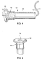
- Fig. 1 illustrates an example of a analyte detecting device according to an embodiment of the present invention
- Fig. 2 is a detailed view of the distal end of the analyte detecting device shown in Fig. 1 ;
- Fig. 3 is a cross-sectional view of the analyte detecting device shown in Fig. 1 ;
- Fig. 4 is an exemplary electrical schematic of the components employed in or used in conjunction with the analyte detecting device shown in Fig. 1 ;
- Fig. 5 is detailed view of an example of an active electrode employed in the analyte detecting device shown in Fig. 1 ;
- Fig. 6 is a detailed cross-sectional view of a portion of the active electrode shown in Fig. 5 ;
- Fig. 7 illustrates an example of the manner in which the analyte detecting device shown in Fig. 1 is used on a patient;
- Fig. 8 is a graph showing an example of the relationship between current passing through the device shown in Fig. 1 and the glucose concentration in the environment in which the active electrode is inserted;
- Fig. 9 illustrates an example of an analyte detecting device, as shown in Fig. 1 , having a reference electrode;
- Fig. 10 is an example of an analyte detecting device according to another embodiment of the present invention.
- Fig. 11 is an example of a strip of active electrodes for the analyte detecting device according to a further embodiment of the present invention.
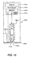
- Fig. 12 illustrates a cross-sectional view of another example of a analyte detecting device as shown in Fig. 1 modified to include an active electrode dispenser according to another embodiment of the present invention
- Figs. 1-6 illustrate an analyte detecting device 100 according to an embodiment of the present invention.
- the device 100 includes a base portion 102 which employs an active electrode 104 and an auxiliary electrode and or in combination therewith, a reference electrode 106 which are described in more detail below.
- the terms counter or reference electrode include combinations thereof as is known in the art.
- the base portion 102 is connected to a housing 108 that extends along the lengthwise direction of the device 100.
- the base portion 102 and housing 108 can therefore act as the base of the device 100 that can be held during operation as described in more detail below.
- the base portion 102 can be fixed or pivotable with respect to the axis of active electrode 104 to any angle, by various means, for example, by constructing base portion 102 from an elastic material or providing a joint such that the active electrode can be inserted at a angle less than or about 90 degrees when the auxiliary electrode 106 is positioned substantially parallel and adjacent to the skin of a patient.
- the active electrode 104 may be located along the axial center or substantially along the axial center of the device 100.
- an auxiliary electrode 106 which may be circular or substantially circular, extends entirely around the active electrode 104.
- Active electrode may alternatively be automatically or manually extendable from the base portion 102 either manually or by mechanical means to insert at least a portion of active electrode 104 through the stratum corneum at any angle greater than zero up to about 90 degrees relative to the surface of the skin to which it is applied.
- the auxiliary electrode 106 can be made entirely of, or be combinations thereof, of any suitable base material, either conductive or non-conductive, such a silicon, plastic, or a metal, or optionally a non-conductive material coated with a conductive material, such as gold, platinum, graphite, palladium, or the like, including thin metal foils or films or metal foils or films supported on plastic, paper, or other flexible material.
- the auxiliary electrode 106 can extend around the entire circumference of the base portion 102 of the device 100 as shown in Figs. 1 and 2 , or can extend along any suitable portion of the circumference of the base portion 102 so as to encircle the active electrode 104 either entirely or partially.
- the auxiliary electrode 106 can also be divided into several semicircular or arcuate shapes.
- the auxiliary electrode 106 need not be circular, but can be any suitable shape such as square, rectangular, oval, or can be any suitable pattern of electrodes.
- the auxiliary electrode 106 can be configured as to contain adjacent to at least a portion of the surface, a conductive gel material or any other suitable conductive material or device.
- Auxiliary electrode 106 can be of suitable construction to provide for conforming closely and or securely to the skin, including the use of adhesive means generally know in the art.
- Auxiliary electrode 106 also includes an abrasive surface which can slightly abrade the surface of the patient's skin, as well as the stratum corneum, to thus establish better electrical contact with the patient.
- the auxiliary electrode 106 can be configured to be minimally invasive to the patient's skin as is the active electrode 104.
- FIG. 3 An exemplary device is shown in Fig. 3 , whereby the active electrode 104 may be coupled to a conductor 110 that extends along the hollow interiors of the base portion 102 and housing 108 of the device 100, while auxiliary electrode 106 is coupled to a conductor 112 that also extends along the hollow interiors of the base portion 102 and housing 108 of the device 100.
- the base portion 102 and housing 108 of the device 100 may be flat or of open-structure to lie substantially flat.
- Conductors 110 or 112 are electrically insulated from each other.
- An exemplary device as illustrated schematically in Fig. 4 , has the active electrode 104 and the counter-electrode 106 coupled to a voltage generating device, such as a potentiostat 114, and a current detector 116, the purposes of which are described in more detail below.
- the active electrode 104 can have a tab portion 118 and a probe portion 120.
- the tab portion 118 can be square-shaped or substantially square-shaped having a width of 1 mm or about 1 mm and a length of 1 mm or about 1 mm.
- the probe portion 120 can have a length ranging from at or about 20 ⁇ m to at or about 5000 ⁇ m.
- the length of the probe portion 120 is preferably small, for example, at or about 100-2000 ⁇ m, so as to be minimally invasive when inserted in the patient's skin as described in more detail below.
- the diameter of the tip of probe 120 is substantially small, for example 100-250 ⁇ m or less.
- the active electrode 104 need not have the configuration shown in Fig. 5 , but rather, can be shaped as a needle, microlance, microneedle, or have any other suitable shape to provide access through the stratum corneum.
- the active electrode 104 can be disposable, that is, used once and replaced with another fresh active electrode 104.
- the active electrode 104 can be removably coupled to the conductor via, for example, a socket arrangement (not shown) so that after use, the active electrode 104 can be removed from the device 100 by hand or through the use of an instrument, and discarded.
- the device 100 can be configured with an ejection tool (not shown) which ejects the active electrode 104. Once the used active electrode 104 has been removed or ejected, another active electrode 104 can be inserted into the device 100.
- the device 100 can be configured with a supply of active electrodes 104, which can be selectably fed to an active location such as that shown in Fig. 1 , and then discarded after use.
- the auxiliary electrode 106 can be reusable or disposable.
- the device 100 can be configured with a retractable mechanism (not shown) that can be controlled to extend the active electrode 104 from the distal end of the device 100 so that the active electrode 104 can enter the patient's stratum corneum when the distal end of the device is placed against the patient's skin as can be appreciated by one skilled in the art.
- the retractable mechanism can further be controlled to retract the active electrode 104 back into an opening in the distal end of the device 100 after use.
- the retractable mechanism can be configured as an ejection mechanism to eject the active electrode 104 after use so that a fresh active electrode 104 can be installed.
- Fig. 6 is a cross-sectional view of a portion of an exemplary probe portion 120 of the active electrode 104 as shown in Fig. 5 .
- the probe portion 120 is made of a base material 122, such a silicon substrate, stainless steel, plastic, or any other suitable material.
- the base material 122 is coated with a conductor, such as platinum, gold, graphite, palladium, or any other suitable material 124.
- the base material 122 can be sputter-coated with platinum to form the conductive layer 124.
- a substance 126 adjacent to at least a portion of 124 for example, glucose oxidase containing layer 126, is applied to the conductive layer 124 in an immobilization matrix as illustrated.
- the glucose oxidase can be dissolved in aqueous media and dispensed onto conductive layer 124 followed by exposure to glutaraldehyde solution, and allow to dry. Upon drying, the glucose oxidase enzyme becomes cross-linked on the surface of the base material 122. Or the enzyme can be immobilized by spin coating an aqueous solution of enzyme and a UV crosslinkable polyvinyl alcohol modified polymer. An interference film 128 can then be applied over the glucose oxidase layer 126 as shown. Glucose oxidase enzyme immobilization methods and interference films for reducing extraneous signal from electro-active species found in biological fluids are well known in the art. Additionally, mediators can be included in the layer 126 as is known in the art.
- the active electrode 104 can be coated with differed types or combinations of enzymes, such as glucose oxidase, dehydrogenase, lactate dehydrogenase, and so on, and can use non-enzymatic molecular recognition chemicals capable of redox chemistry, otherwise known as electrochemically responsive receptors, to detect different types of components in the patient, all of which are known in the art. It is also noted that the active electrode 104 can be substantially free of any substance or enzyme as taught by Jung, S. K. et al., Analytical Chemistry, 71: 3642-3649 (1999 ); Gorski et al., J. Electroanalytical Chem. 425 (1-2): 191-199 (1997 ); and Zen et al., Analyst, 125 (12): 2169-2172 (2000 ).
- enzymes such as glucose oxidase, dehydrogenase, lactate dehydrogenase, and so on
- non-enzymatic molecular recognition chemicals capable of redox
- the device 100 can be used to measure electrochemically active components such as electrolytes, oxygen, nitric oxide, lactate, insulin, neurotransmitters, drugs, and other analytes in the patient's body, as well as other characteristics such as the pH level in the patient's blood, the patient's temperature, resistance of the patient's skin, and so on.
- the reaction that occurs on the active electrode 104 can thus be a direct measure of electro-active species such as oxygen, nitric oxide, and so on, or the reaction can rely on enzymes to enable electrochemical detection such as glucose oxidase, glucose dehydrogenase, lactate dehydrogenase, as discussed above.
- analyte includes electrochemically active species present in the patient as well as electrochemically active reaction products or by-products of species present in the patient with substances in layer 126.
- the device 100 can be configured with many types of materials, such as metals, ceramics, or plastics, and the electronics shown in Fig. 4 can be integrated into the device 100, if desired. Additionally, device 100 can be integrated with any drug delivery device. Drug delivery devices include infusion, pump, transdermal, syringe, gas-assisted particle injectors, electroporation, intra- and interdermal injection devices for introducing liquid, particles, suspensions, emulsions, nanoparticles, micelles, liposomes and the like. Additionally, device 100 can be integrated with any drug delivery device to provide "closed-loop" control of monitoring and delivery of drugs, nucleic acids, or proteins.
- the active electrode 104 and auxiliary electrode 106 can be brought into contact with the surface of a patient's skin 130, such as the surface of the patient's arm.
- the active electrode 104 By extending active electrode 104 from the base portion 102 either with mild pressure or by way of mechanical means, the active electrode 104 will pass through the stratum corneum of the patient's skin 130, while the auxiliary electrode 106 will rest on the surface of the patient's skin 130.
- a plurality of active electrodes 104 are provided suitable for indexing sequentially within the base portion 102 and auxiliary electrode 106 for use followed by storage of used active electrodes for ease and save disposal thereof. Indexing of the plurality of electrodes is achieved using mechanical means suitable for such manipulation as known in the art.
- the active electrode 104 or the substance adjacent thereto electrochemically interacts with analyte in the tissue, or blood or interstitial fluid thus providing a detectable signal.
- the substance is glucose oxidase and the analyte is glucose
- the device 100 is placed against the skin and active electrode 100 is passed through the stratum corneum to a depth sufficient to access the analyte, the following electrochemical reaction occurs:
- oxygen is converted to hydrogen peroxide (H 2 O 2 ) in the absence of mediators.
- the potentiostat 114 (see Fig. 4 ) can then be controlled to apply a potential to the active electrode 104 to place the active electrode 104 at an effective electric potential relative to the electrical potential of the patient's skin and preferably relative to the electrical potential of the auxiliary electrode 106.
- effective electric potential it is understood to mean a potential suitable to oxidize any or all of the electrochemically active analyte or species, for example, hydrogen peroxide generated by the glucose-glucose oxidase reaction set forth above, and induce a measurable electrical current to flow through the device 100 and, in particular, through the patient's skin 130 between the active electrode 104 and auxiliary electrode 106.
- the effective electric potential as is known in the art, is dependent on the metal substrate 124 chosen.
- the applied effective potential may be applied in a variety of ways as required by the specific application, including but not limited to ramped, stepped, pulsed, programmed pulse, and combinations thereof.
- the magnitude of this current is related to the concentration of glucose in the patient. As shown, for example, in the graph of Fig. 8 , the magnitude of current increases as the glucose level increases.
- Current detector 116 can monitor the current that is flowing thought the device 100.
- the current detector can be coupled to a controller (not shown), such as a microcomputer, which interprets the current in accordance with the graph shown in Fig. 8 to determine glucose level in the patient's blood.
- the detector can be configured as is known in the art to measure current or charge directly, or derivatives thereof.
- the active electrode 104 must be maintained at a specific electrical potential relative to the surrounding medium, for example, the patient's skin. This potential is typically within the range from at or about - 0.6 V to at or about +0.6 V, depending on the electrochemistry of the analyte at the active electrode 104 and the nature of the metal substrate 124.
- auxiliary electrode 106 is separated from the active electrode 104 by a certain distance (e.g., up to about 1 centimeter), a voltage drop (an "IR" drop) occurs between the active electrode 104 and the auxiliary electrode 106 due to the resistance of the patient's skin between these electrodes when the device 100 is applied to the patient's skin. Furthermore, because this IR drop varies due to a multitude of skin conditions and characteristics of the electrodes 104 and 106, the auxiliary electrode 106 may not be suitable as a reference potential for the electrical potential applied to the active electrode 104.
- the device 100 can include a reference electrode 132 positioned near to or adjacent the active electrode 104, so that the reference electrode 132 is in the electric field that is generated between the active electrode 104 and auxiliary electrode 106.
- This reference electrode 132 is electrically coupled to the power supply.
- the reference electrode can be integral with and electrically isolated from either the active electrode or the auxiliary electrode.
- the tip portion of probe 120 of the active electrode 104 See Figs. 5 and 6 ) can have the reference electrode adjacent to the active electrode on one side only or side by side on the same side, provided they are electrically isolated (from active electrode).
- the reference electrode 132 is positioned close to the active electrode 104 and thus, only a slight amount of the patient's skin is present between these electrodes when the device 100 is placed on the patient's skin 130, there is only a negligible IR drop between the active electrode 104 and the reference electrode 132 due to the patient's skin 130. Furthermore, since the IR drop is negligible, variations in skin conditions have little overall effect on the magnitude of this IR drop, thus ensuring that the correct electrical potential is being applied to the active electrode 104 during the measurement.
- the probe portion 120 of the active electrode 104 can have the glucose oxidase coating on one side only, and an electrically isolated conductive coating on the other side to enable that side of the active electrode 104 to act as the reference electrode.
- the device 100 can have any suitable shape.
- the device can have a cylindrical shape as does device 100-1, and can include multiple active electrodes 104-1, as well as one or more reference electrodes 132-1, surrounded by an auxiliary electrode 106-1.
- the multiple active electrodes 104-1 can be coated with different types or concentrations of enzymes as discussed above (or with none at all) to simultaneously detect different types of components or parameters as discussed above.
- each different active electrode 104-1 is coupled, for example, to a respective input of a processor (not shown), or are otherwise discernable by the processor, so that the processor can interpret the different measurements.
- the device 100 and its variations discussed above can be combined with a drug or medicament or medication delivery device, such as an insulin delivery device (not shown), which would automatically deliver the appropriate amount of insulin to the patient to correct the patient's blood glucose level.
- a drug or medicament or medication delivery device such as an insulin delivery device (not shown)
- the device 100 and its variations can communicate with another instrument to recommend an action by the instrument or to adjust the action of an instrument.
- the device 100 and its variations can include a memory for storing information such as readings obtained by the device 100, or information provided by other instruments.
- the device 100 and its variations can be wearable like a watch or bracelet so that it can operation as a continuous or substantially continuous monitoring system.
- the probe portion 120 active electrode 104 can also be coated with a sorbent coating so that when the active electrode 104 comes in contact with the fluid in the patient's skin 130, it immediately captures the fluid and therefore it does not have to reside in the patient's skin for a long period of time to take a reading.
- the active electrode 104 can be further configured as a hollow lumen, and the substance adjacent to the active electrode, such as for example glucose oxidase, can be placed inside the lumen. In this configuration, multiple openings can be placed in the lumen to allow free and rapid penetration of the component of interest (e.g., glucose) in the patient's skin 130 to enter the lumen. In this lumen configuration, selective layers can be placed over the openings or as a coating over the device 100 to prevent interfering species, such as ascorbate, urate, and acetaminophen, from encountering the active electrode 104.
- interfering species such as ascorbate, urate, and acetaminophen
- multiple active electrodes 104-2 can be configured along a strip 105-2, which can be employed in an alternative configuration of the device 100-2 as shown in Fig. 12 . That is, the device 100-3 can be configured as a dispenser for dispensing a plurality of active electrodes 104-2. As indicated, the strip 105-2 of active electrodes 104-2 can be loaded into the device 100-2 so that the device 100-2 thus contains a plurality of active electrodes 104-2 that can be fed sequentially as needed to provide a sterile, disposable component capable of storing the microprobes after use to minimize accidental injury.
- the device 100-2 further includes an auxiliary electrode 106-2 which can be similar to the auxiliary electrodes discussed above.
- the device 100-2 can further include a power supply 107-2 for providing an electrical potential across the active electrodes 104-2 and the auxiliary electrode 106-2.
- the active electrodes 104-2 can be coupled to the strip 105-2 that is capable of conducting current from the anode of the power supply 107-2 to the active electrodes 104-2.
- a cartridge changing button (not shown) can be pressed to rotate the strip 105-2 about pulleys 109-2 to place another active electrode 104-2 at the active location 111-2 for taking a reading.
- the device 100-2 further includes a memory 113-2 for storing readings that have been taken in the manner described above for device 100, a display 115-2 for displaying the readings, and a controller 117-2 for controlling the operations of the power supply 107-2, memory 113-2, display 115-2 and any of the other components discussed above.
- the device 100-2 also includes an active electrode extender shown schematically as item 119-2 in Fig. 12 , which can be controlled to extend and retract the active electrode 104-2 out from and into the device 100-2, respectively, for use.
- the extender 119-2 can further be configured to eject the active electrode 104-2 after use as can be appreciated by one skilled in the art.
- the auxiliary electrode 106-2 can be similarly extendable and retractable.
- each active electrode 104-2 can be configured to have a portion which acts as the active electrode, and another portion, electrically isolated from the active electrode portion, that acts as a reference electrode like reference electrode 132 discussed above.
- the strip 105-2 can be divided into two electrically isolated sections, one of which contacting the active portion of the active electrodes 104-2 and the other contacting the reference electrode portion of the active electrodes 104-2.
- the pulleys 109-2 can likewise be segregated to conduct separate paths of current to the separate portions of the strip 105-2 and thus, to the active and control portions of the active electrodes 104-2. The controller 115-2 can thus distinguish from the currents flowing through the active and control portions of the active electrode 104-2.
- the device 100-2 can be configured to perform all the functions discussed above with regard to device 100 discussed above, to detect all of the components as discussed above. Also, the device 100-2 can be configured to communicate with another instrument to recommend an action by the instrument or to adjust the action of an instrument. Furthermore, the device 100-2 can be wearable like a watch or bracelet so that it can operation as a continuous or substantially continuous monitoring system.
Abstract
Description
- The present invention relates to a minimally-invasive system and method for monitoring analyte levels in a patient. More particularly, the present invention relates to a system and method employing a device which includes a micro probe functioning as an active electrode and a auxiliary electrode surrounding at least a portion of the active electrode, arranged to be placed against the skin of a patient to detect analyte levels in the patient with minimal pain and damage to the patient's skin.
- People having diabetes must monitor their blood glucose level on a regular basis to assure that their blood glucose level remains within normal limits necessary to maintain a healthy living condition. Low glucose levels, known as hypoglycemia, can cause mental confusion and, in more extreme instances, coma and ultimately death. On the other hand, high blood glucose levels, known as hyperglycemia, can cause chronic symptoms such frequent urination and thirst, and if sustained over long periods of time, can result in damage to blood vessels, eyes, kidneys and other organs of the body.
- Some people having mild diabetes can regulate their blood glucose levels through diet. However, people having moderate or severe forms of diabetes must take insulin to sustain acceptable blood glucose levels.
- Conventional methods of monitoring blood glucose levels directly monitor the concentration of glucose in a small sample of blood taken from the person. Accordingly, if the person wishes to test his or her blood glucose level, the person can use a small needle or lance to puncture, for example his or her fingertip and drain a droplet of blood into the sampling device. However, this invasive method is painful to the person. Moreover, precautions must be taken sterilize the area in which the puncture is made, as well as the puncturing instrument, so that a pathogen is not introduced into the person's bloodstream. These methods can also be somewhat messy and unsanitary, and somewhat time consuming.
- As an alternative to the conventional invasive techniques, miniaturized glucose sensing needles have been developed over the past several years. These types of devices typically include a metal substrate with an enzyme as an active electrode and an adjacent metal substrate that serve as the return and reference electrodes. The enzyme, typically glucose oxidase, catalyzes the oxidation of glucose, and the byproducts of the reaction are measured electrochemically at the active electrode. The electrochemical measurement is affected by imposing an electrical potential between the active and the counter/reference (auxiliary) electrodes. At a particular potential, electric current begins to flow as a consequence of the chemical reaction at the electrodes. The current is related to the concentration of the electro-active species, which is in turn governed by the amount of glucose in the test medium. In the case of conventional glucose strips, the test medium is capillary blood; in the case of implantable electrodes, the medium is tissue.
- These devices are typically macroscopic or, in other words, more than 200 microns in diameter and often a centimeter or more in length. Accordingly, these devices are invasive, because they can penetrate the skin up to one centimeter deep. Additionally, these devices typically employ conventional needles, wires and multi-layer plastic substrates which require complicated multi-step manufacturing processes that are both time consuming and expensive. Examples of known glucose sensing devices are described in
U.S. Patent Nos. 4,953,552 ,5,680,858 and5,820,570 , and inPCT publication WO 98/46124 - Maximizing the active electrode area increases the current response of the system. Especially in the case of the implantable system, the active electrode area is small - often ten-fold smaller than strip-based electrodes. Furthermore, the active and return/reference electrodes often share the same substrate - further limiting the available active area. One advantage of the invention described herein is that the return electrode is separated from the active electrode substrate and can be positioned on the surface of the skin, at least partially surrounding the minimally-invasive working electrode. This configuration allows maximum usage of the active electrode, and it permits the use of a large external return electrode. Both aspects improve the signal and performance of the system, while maintaining the small minimally invasive, pain-free format of the design.
- Accordingly, a need exists for an improved minimally invasive system for monitoring analyte levels in patients.
WO 96/14026
EP 0 964 060 A2 - The device of the invention is defined by the features in independent claim 1 and the method of the invention is defined by the features in independent claim 19.
The present invention relates to a system and method for detecting an analyte component, such as glucose, in a patient. The system and method employ a device comprising an active electrode optionally coated with a substance, such as glucose oxidase, and a counter-electrode that is configured to surround at least a portion of the active electrode. The configuration of the counter and active electrode improves the current flow through the device and increases the sensitivity of the device. When the device and method are used to detect the analyte of a patient, the active electrode may have a portion thereof adjacent to a substance, for example, glucose oxidase, and a length such that when the device is placed against the patient's skin, the active electrode is adapted to pass through the stratum corneum of the patient, preferably to a depth at which few nerve endings reside, to enable the analyte in the patient to be electrochemically detected, either directly or, for example, by reaction with a substance on the portion of the active electrode to produce an electrochemically detectable species. As stated above, the auxiliary electrode is configured to surround at skin when the device is placed against the patient's skin. The active electrode extends beyond a base portion of the device to a length suitable to access the analyte, and the auxiliary electrode is coupled to a surface of the base portion proximate to that from which the active electrode extends. The active electrode is further adapted to have applied to its electric potential to measure a reaction between the analyte in the patient and the substance adjacent to the active electrode. The device can further include a reference electrode, disposed at a distance from the active electrode less than or equal to a distance between the active electrode and any portion of the auxiliary electrode, or adjacent to the active electrode, or integral with the auxiliary electrode, so that the reference electrode acts as a reference potential for the electrical potential applied to the active electrode. The reference electrode can thus be used to compensate for changes in resistivity of the skin which can effect the accuracy of the device. - These and other features and advantages of the present invention will be more readily appreciated from the following detailed description when read in conjunction with the appended drawings, in which:
-
Fig. 1 illustrates an example of a analyte detecting device according to an embodiment of the present invention; -
Fig. 2 is a detailed view of the distal end of the analyte detecting device shown inFig. 1 ; -
Fig. 3 is a cross-sectional view of the analyte detecting device shown inFig. 1 ; -
Fig. 4 is an exemplary electrical schematic of the components employed in or used in conjunction with the analyte detecting device shown inFig. 1 ; -
Fig. 5 is detailed view of an example of an active electrode employed in the analyte detecting device shown inFig. 1 ; -
Fig. 6 is a detailed cross-sectional view of a portion of the active electrode shown inFig. 5 ; -
Fig. 7 illustrates an example of the manner in which the analyte detecting device shown inFig. 1 is used on a patient; -
Fig. 8 is a graph showing an example of the relationship between current passing through the device shown inFig. 1 and the glucose concentration in the environment in which the active electrode is inserted; -
Fig. 9 illustrates an example of an analyte detecting device, as shown inFig. 1 , having a reference electrode; -
Fig. 10 is an example of an analyte detecting device according to another embodiment of the present invention; -
Fig. 11 is an example of a strip of active electrodes for the analyte detecting device according to a further embodiment of the present invention; and -
Fig. 12 illustrates a cross-sectional view of another example of a analyte detecting device as shown inFig. 1 modified to include an active electrode dispenser according to another embodiment of the present invention -
Figs. 1-6 illustrate ananalyte detecting device 100 according to an embodiment of the present invention. As shown inFig. 1 , thedevice 100 includes abase portion 102 which employs anactive electrode 104 and an auxiliary electrode and or in combination therewith, areference electrode 106 which are described in more detail below. As used herein, the terms counter or reference electrode include combinations thereof as is known in the art. Thebase portion 102 is connected to ahousing 108 that extends along the lengthwise direction of thedevice 100. Thebase portion 102 andhousing 108 can therefore act as the base of thedevice 100 that can be held during operation as described in more detail below. Thebase portion 102 can be fixed or pivotable with respect to the axis ofactive electrode 104 to any angle, by various means, for example, by constructingbase portion 102 from an elastic material or providing a joint such that the active electrode can be inserted at a angle less than or about 90 degrees when theauxiliary electrode 106 is positioned substantially parallel and adjacent to the skin of a patient. - As shown in exemplary
Figs. 1-3 theactive electrode 104 may be located along the axial center or substantially along the axial center of thedevice 100. Also, anauxiliary electrode 106, which may be circular or substantially circular, extends entirely around theactive electrode 104. Active electrode may alternatively be automatically or manually extendable from thebase portion 102 either manually or by mechanical means to insert at least a portion ofactive electrode 104 through the stratum corneum at any angle greater than zero up to about 90 degrees relative to the surface of the skin to which it is applied. Theauxiliary electrode 106 can be made entirely of, or be combinations thereof, of any suitable base material, either conductive or non-conductive, such a silicon, plastic, or a metal, or optionally a non-conductive material coated with a conductive material, such as gold, platinum, graphite, palladium, or the like, including thin metal foils or films or metal foils or films supported on plastic, paper, or other flexible material. Theauxiliary electrode 106 can extend around the entire circumference of thebase portion 102 of thedevice 100 as shown inFigs. 1 and 2 , or can extend along any suitable portion of the circumference of thebase portion 102 so as to encircle theactive electrode 104 either entirely or partially. Theauxiliary electrode 106 can also be divided into several semicircular or arcuate shapes. Alternatively, theauxiliary electrode 106 need not be circular, but can be any suitable shape such as square, rectangular, oval, or can be any suitable pattern of electrodes. Furthermore, theauxiliary electrode 106 can be configured as to contain adjacent to at least a portion of the surface, a conductive gel material or any other suitable conductive material or device.Auxiliary electrode 106 can be of suitable construction to provide for conforming closely and or securely to the skin, including the use of adhesive means generally know in the art.Auxiliary electrode 106 also includes an abrasive surface which can slightly abrade the surface of the patient's skin, as well as the stratum corneum, to thus establish better electrical contact with the patient. Furthermore, theauxiliary electrode 106 can be configured to be minimally invasive to the patient's skin as is theactive electrode 104. - An exemplary device is shown in
Fig. 3 , whereby theactive electrode 104 may be coupled to aconductor 110 that extends along the hollow interiors of thebase portion 102 andhousing 108 of thedevice 100, whileauxiliary electrode 106 is coupled to aconductor 112 that also extends along the hollow interiors of thebase portion 102 andhousing 108 of thedevice 100. Alternatively, thebase portion 102 andhousing 108 of thedevice 100 may be flat or of open-structure to lie substantially flat.Conductors Fig. 4 , has theactive electrode 104 and the counter-electrode 106 coupled to a voltage generating device, such as apotentiostat 114, and acurrent detector 116, the purposes of which are described in more detail below. - As shown in
Fig. 5 , theactive electrode 104 can have atab portion 118 and aprobe portion 120. In this example, thetab portion 118 can be square-shaped or substantially square-shaped having a width of 1 mm or about 1 mm and a length of 1 mm or about 1 mm. Theprobe portion 120 can have a length ranging from at or about 20 µm to at or about 5000 µm. However, the length of theprobe portion 120 is preferably small, for example, at or about 100-2000 µm, so as to be minimally invasive when inserted in the patient's skin as described in more detail below. In addition, the diameter of the tip ofprobe 120 is substantially small, for example 100-250µm or less. Also, theactive electrode 104 need not have the configuration shown inFig. 5 , but rather, can be shaped as a needle, microlance, microneedle, or have any other suitable shape to provide access through the stratum corneum. - Furthermore, the
active electrode 104 can be disposable, that is, used once and replaced with another freshactive electrode 104. In other words, theactive electrode 104 can be removably coupled to the conductor via, for example, a socket arrangement (not shown) so that after use, theactive electrode 104 can be removed from thedevice 100 by hand or through the use of an instrument, and discarded. Alternatively, thedevice 100 can be configured with an ejection tool (not shown) which ejects theactive electrode 104. Once the usedactive electrode 104 has been removed or ejected, anotheractive electrode 104 can be inserted into thedevice 100. - Also, as discussed in more detail below with regard to
Figs. 11 and12 , thedevice 100 can be configured with a supply ofactive electrodes 104, which can be selectably fed to an active location such as that shown inFig. 1 , and then discarded after use. Likewise, theauxiliary electrode 106 can be reusable or disposable. In addition, thedevice 100 can be configured with a retractable mechanism (not shown) that can be controlled to extend theactive electrode 104 from the distal end of thedevice 100 so that theactive electrode 104 can enter the patient's stratum corneum when the distal end of the device is placed against the patient's skin as can be appreciated by one skilled in the art. The retractable mechanism can further be controlled to retract theactive electrode 104 back into an opening in the distal end of thedevice 100 after use. Alternatively, the retractable mechanism can be configured as an ejection mechanism to eject theactive electrode 104 after use so that a freshactive electrode 104 can be installed. -
Fig. 6 is a cross-sectional view of a portion of anexemplary probe portion 120 of theactive electrode 104 as shown inFig. 5 . As illustrated, theprobe portion 120 is made of abase material 122, such a silicon substrate, stainless steel, plastic, or any other suitable material. Thebase material 122 is coated with a conductor, such as platinum, gold, graphite, palladium, or any othersuitable material 124. For example, thebase material 122 can be sputter-coated with platinum to form theconductive layer 124. Asubstance 126 adjacent to at least a portion of 124, for example, glucoseoxidase containing layer 126, is applied to theconductive layer 124 in an immobilization matrix as illustrated. For example, the glucose oxidase can be dissolved in aqueous media and dispensed ontoconductive layer 124 followed by exposure to glutaraldehyde solution, and allow to dry. Upon drying, the glucose oxidase enzyme becomes cross-linked on the surface of thebase material 122. Or the enzyme can be immobilized by spin coating an aqueous solution of enzyme and a UV crosslinkable polyvinyl alcohol modified polymer. Aninterference film 128 can then be applied over theglucose oxidase layer 126 as shown. Glucose oxidase enzyme immobilization methods and interference films for reducing extraneous signal from electro-active species found in biological fluids are well known in the art. Additionally, mediators can be included in thelayer 126 as is known in the art. - It is also noted that the
active electrode 104 can be coated with differed types or combinations of enzymes, such as glucose oxidase, dehydrogenase, lactate dehydrogenase, and so on, and can use non-enzymatic molecular recognition chemicals capable of redox chemistry, otherwise known as electrochemically responsive receptors, to detect different types of components in the patient, all of which are known in the art. It is also noted that theactive electrode 104 can be substantially free of any substance or enzyme as taught by Jung, S. K. et al., Analytical Chemistry, 71: 3642-3649 (1999); Gorski et al., J. Electroanalytical Chem. 425 (1-2): 191-199 (1997); and Zen et al., Analyst, 125 (12): 2169-2172 (2000). - For example, the
device 100 can be used to measure electrochemically active components such as electrolytes, oxygen, nitric oxide, lactate, insulin, neurotransmitters, drugs, and other analytes in the patient's body, as well as other characteristics such as the pH level in the patient's blood, the patient's temperature, resistance of the patient's skin, and so on. The reaction that occurs on theactive electrode 104 can thus be a direct measure of electro-active species such as oxygen, nitric oxide, and so on, or the reaction can rely on enzymes to enable electrochemical detection such as glucose oxidase, glucose dehydrogenase, lactate dehydrogenase, as discussed above. It is understood that the term analyte includes electrochemically active species present in the patient as well as electrochemically active reaction products or by-products of species present in the patient with substances inlayer 126. Also, thedevice 100 can be configured with many types of materials, such as metals, ceramics, or plastics, and the electronics shown inFig. 4 can be integrated into thedevice 100, if desired. Additionally,device 100 can be integrated with any drug delivery device. Drug delivery devices include infusion, pump, transdermal, syringe, gas-assisted particle injectors, electroporation, intra- and interdermal injection devices for introducing liquid, particles, suspensions, emulsions, nanoparticles, micelles, liposomes and the like. Additionally,device 100 can be integrated with any drug delivery device to provide "closed-loop" control of monitoring and delivery of drugs, nucleic acids, or proteins. - The operation of the
device 100 will now be described. As shown inFig. 7 , when thedevice 100 is used to detect the analyte of interest in the patient, theactive electrode 104 andauxiliary electrode 106 can be brought into contact with the surface of a patient'sskin 130, such as the surface of the patient's arm. By extendingactive electrode 104 from thebase portion 102 either with mild pressure or by way of mechanical means, theactive electrode 104 will pass through the stratum corneum of the patient'sskin 130, while theauxiliary electrode 106 will rest on the surface of the patient'sskin 130. It is noted that since the length of theactive electrode 104 is 100-2000µm, theactive electrode 104 will only penetrate minimally into the patent'sskin 130, and will reduce or eliminate substantially the tendency of the patient to bleed, nor will it contact the nerve endings in the patient'sskin 130 to cause the patient discomfort. In an alternative embodiment, a plurality ofactive electrodes 104 are provided suitable for indexing sequentially within thebase portion 102 andauxiliary electrode 106 for use followed by storage of used active electrodes for ease and save disposal thereof. Indexing of the plurality of electrodes is achieved using mechanical means suitable for such manipulation as known in the art. - Once through the stratum corneum, the
active electrode 104 or the substance adjacent thereto electrochemically interacts with analyte in the tissue, or blood or interstitial fluid thus providing a detectable signal. For example, when the substance is glucose oxidase and the analyte is glucose, when thedevice 100 is placed against the skin andactive electrode 100 is passed through the stratum corneum to a depth sufficient to access the analyte, the following electrochemical reaction occurs:
- As can be appreciated by one skilled in the art, in accordance with the above reaction, oxygen is converted to hydrogen peroxide (H2O2) in the absence of mediators. The potentiostat 114 (see
Fig. 4 ) can then be controlled to apply a potential to theactive electrode 104 to place theactive electrode 104 at an effective electric potential relative to the electrical potential of the patient's skin and preferably relative to the electrical potential of theauxiliary electrode 106. By effective electric potential, it is understood to mean a potential suitable to oxidize any or all of the electrochemically active analyte or species, for example, hydrogen peroxide generated by the glucose-glucose oxidase reaction set forth above, and induce a measurable electrical current to flow through thedevice 100 and, in particular, through the patient'sskin 130 between theactive electrode 104 andauxiliary electrode 106. The effective electric potential, as is known in the art, is dependent on themetal substrate 124 chosen. The applied effective potential may be applied in a variety of ways as required by the specific application, including but not limited to ramped, stepped, pulsed, programmed pulse, and combinations thereof. - The magnitude of this current is related to the concentration of glucose in the patient. As shown, for example, in the graph of
Fig. 8 , the magnitude of current increases as the glucose level increases.Current detector 116 can monitor the current that is flowing thought thedevice 100. The current detector can be coupled to a controller (not shown), such as a microcomputer, which interprets the current in accordance with the graph shown inFig. 8 to determine glucose level in the patient's blood. The detector can be configured as is known in the art to measure current or charge directly, or derivatives thereof. - It is further noted that variations in the condition of the patient's
skin 130 can possibly affect the accuracy of the readings, because such variations can alter the level of current flow. As discussed in the example above, theactive electrode 104 must be maintained at a specific electrical potential relative to the surrounding medium, for example, the patient's skin. This potential is typically within the range from at or about - 0.6 V to at or about +0.6 V, depending on the electrochemistry of the analyte at theactive electrode 104 and the nature of themetal substrate 124. Because theauxiliary electrode 106 is separated from theactive electrode 104 by a certain distance (e.g., up to about 1 centimeter), a voltage drop (an "IR" drop) occurs between theactive electrode 104 and theauxiliary electrode 106 due to the resistance of the patient's skin between these electrodes when thedevice 100 is applied to the patient's skin. Furthermore, because this IR drop varies due to a multitude of skin conditions and characteristics of theelectrodes auxiliary electrode 106 may not be suitable as a reference potential for the electrical potential applied to theactive electrode 104. - Accordingly, as shown by way of example in
Fig. 9 , thedevice 100 can include areference electrode 132 positioned near to or adjacent theactive electrode 104, so that thereference electrode 132 is in the electric field that is generated between theactive electrode 104 andauxiliary electrode 106. Thisreference electrode 132 is electrically coupled to the power supply. However, the reference electrode can be integral with and electrically isolated from either the active electrode or the auxiliary electrode. For example, the tip portion ofprobe 120 of the active electrode 104 (SeeFigs. 5 and 6 ) can have the reference electrode adjacent to the active electrode on one side only or side by side on the same side, provided they are electrically isolated (from active electrode). Because thereference electrode 132 is positioned close to theactive electrode 104 and thus, only a slight amount of the patient's skin is present between these electrodes when thedevice 100 is placed on the patient'sskin 130, there is only a negligible IR drop between theactive electrode 104 and thereference electrode 132 due to the patient'sskin 130. Furthermore, since the IR drop is negligible, variations in skin conditions have little overall effect on the magnitude of this IR drop, thus ensuring that the correct electrical potential is being applied to theactive electrode 104 during the measurement. For example, theprobe portion 120 of the active electrode 104 (seeFigs. 5 and 6 ) can have the glucose oxidase coating on one side only, and an electrically isolated conductive coating on the other side to enable that side of theactive electrode 104 to act as the reference electrode. - It is further noted that additional variations to the
device 100 discussed above can be made. For example, thedevice 100 can have any suitable shape. As shown inFig. 10 , the device can have a cylindrical shape as does device 100-1, and can include multiple active electrodes 104-1, as well as one or more reference electrodes 132-1, surrounded by an auxiliary electrode 106-1. By employing multiple active electrodes 104-1, a plurality of parallel measurements can be taken, thus increasing the overall signal strength of the measurements without increasing pain to the patient. Alternatively, the multiple active electrodes 104-1 can be coated with different types or concentrations of enzymes as discussed above (or with none at all) to simultaneously detect different types of components or parameters as discussed above. In this arrangement, each different active electrode 104-1 is coupled, for example, to a respective input of a processor (not shown), or are otherwise discernable by the processor, so that the processor can interpret the different measurements. - In addition, the
device 100 and its variations discussed above can be combined with a drug or medicament or medication delivery device, such as an insulin delivery device (not shown), which would automatically deliver the appropriate amount of insulin to the patient to correct the patient's blood glucose level. In other words, thedevice 100 and its variations can communicate with another instrument to recommend an action by the instrument or to adjust the action of an instrument. Thedevice 100 and its variations can include a memory for storing information such as readings obtained by thedevice 100, or information provided by other instruments. Furthermore, thedevice 100 and its variations can be wearable like a watch or bracelet so that it can operation as a continuous or substantially continuous monitoring system. - The
probe portion 120active electrode 104 can also be coated with a sorbent coating so that when theactive electrode 104 comes in contact with the fluid in the patient'sskin 130, it immediately captures the fluid and therefore it does not have to reside in the patient's skin for a long period of time to take a reading. Theactive electrode 104 can be further configured as a hollow lumen, and the substance adjacent to the active electrode, such as for example glucose oxidase, can be placed inside the lumen. In this configuration, multiple openings can be placed in the lumen to allow free and rapid penetration of the component of interest (e.g., glucose) in the patient'sskin 130 to enter the lumen. In this lumen configuration, selective layers can be placed over the openings or as a coating over thedevice 100 to prevent interfering species, such as ascorbate, urate, and acetaminophen, from encountering theactive electrode 104. - As shown in
Fig. 11 , multiple active electrodes 104-2 can be configured along a strip 105-2, which can be employed in an alternative configuration of the device 100-2 as shown inFig. 12 . That is, the device 100-3 can be configured as a dispenser for dispensing a plurality of active electrodes 104-2. As indicated, the strip 105-2 of active electrodes 104-2 can be loaded into the device 100-2 so that the device 100-2 thus contains a plurality of active electrodes 104-2 that can be fed sequentially as needed to provide a sterile, disposable component capable of storing the microprobes after use to minimize accidental injury. The device 100-2 further includes an auxiliary electrode 106-2 which can be similar to the auxiliary electrodes discussed above. The device 100-2 can further include a power supply 107-2 for providing an electrical potential across the active electrodes 104-2 and the auxiliary electrode 106-2. - That is, as indicated, the active electrodes 104-2 can be coupled to the strip 105-2 that is capable of conducting current from the anode of the power supply 107-2 to the active electrodes 104-2. A cartridge changing button (not shown) can be pressed to rotate the strip 105-2 about pulleys 109-2 to place another active electrode 104-2 at the active location 111-2 for taking a reading. The device 100-2 further includes a memory 113-2 for storing readings that have been taken in the manner described above for
device 100, a display 115-2 for displaying the readings, and a controller 117-2 for controlling the operations of the power supply 107-2, memory 113-2, display 115-2 and any of the other components discussed above. The device 100-2 also includes an active electrode extender shown schematically as item 119-2 inFig. 12 , which can be controlled to extend and retract the active electrode 104-2 out from and into the device 100-2, respectively, for use. The extender 119-2 can further be configured to eject the active electrode 104-2 after use as can be appreciated by one skilled in the art. The auxiliary electrode 106-2 can be similarly extendable and retractable. - It is also noted that each active electrode 104-2 can be configured to have a portion which acts as the active electrode, and another portion, electrically isolated from the active electrode portion, that acts as a reference electrode like
reference electrode 132 discussed above. In this arrangement, the strip 105-2 can be divided into two electrically isolated sections, one of which contacting the active portion of the active electrodes 104-2 and the other contacting the reference electrode portion of the active electrodes 104-2. The pulleys 109-2 can likewise be segregated to conduct separate paths of current to the separate portions of the strip 105-2 and thus, to the active and control portions of the active electrodes 104-2. The controller 115-2 can thus distinguish from the currents flowing through the active and control portions of the active electrode 104-2. - In addition, the device 100-2 can be configured to perform all the functions discussed above with regard to
device 100 discussed above, to detect all of the components as discussed above. Also, the device 100-2 can be configured to communicate with another instrument to recommend an action by the instrument or to adjust the action of an instrument. Furthermore, the device 100-2 can be wearable like a watch or bracelet so that it can operation as a continuous or substantially continuous monitoring system. - Although only a few exemplary embodiments of this invention have been described in detail above, those skilled in the art will readily appreciate that many modifications are possible in the exemplary embodiments without materially departing from the novel teachings and advantages of this invention. Accordingly, all such modifications are intended to be included within the scope of this invention as defined in the following claims.
Claims (29)
- A device (100) for detecting at least one analyte in a patient, comprising:at least one active electrode (104), said active electrode having a length in the range of 100 - 2000 µm for passing through the stratum corneum to access said analyte to enable the electrochemical detection of said analyte;an auxiliary electrode (106) configured to at least partially surround said active electrode, and adapted to contact patient's skin when the device is placed against said patient, wherein said device further includes a base portion (102) integral with said auxiliary electrode;characterized in thatsaid active electrode is retractable into said base portion and extendable beyond said base portion for accessing said analyte, andsaid auxiliary electrode (106) has an abrasive surface which is adapted to contact and abrade the patient's skin.
- A device (100) as claimed in claim 1, wherein:said auxiliary electrode (106) is adapted to pass into the stratum corneum when contacting said patient's skin.
- A device (100) as claimed in claim 1 or 2, further comprising:a data storage, adapted to store information pertaining to said at least one analyte or said patient.
- A device (100) as claimed in one of claims 1-3, further comprising:a communication device, adapted to communicate information between said device and an external device.
- A device (100) as claimed in one of claims 1-4, wherein:said device is adapted for wearing by said patient for a duration of time.
- A device (100) as claimed in one of claims 1-5, wherein:said device is further adapted to detect at least one parameter of said patient, such that said length of said active electrode (104) enables said active electrode to pass through the stratum corneum to said depth sufficient to access a component to enable the electrochemical detection of said parameter; andsaid at least one analyte and said at least one parameter includes at least one of the following:electrolytes, oxygen, nitric oxide, lactate, insulin, neurotransmitters, at least one drug, pH level in the patient's blood, the patient's temperature, resistance of the patient's skin, glucose oxidase, glucose dehydrogenase and lactate dehydrogenase.
- A device (100) as claimed in one of claims 1-6, further comprising a plurality of said active electrodes.
- A device (100) as claimed in one of claims 1-7, wherein:said auxiliary electrode (106) is configured to entirely surround said active electrode (104).
- A device (100) as claimed in one of claims 1-8, wherein:said auxiliary electrode (106) is coupled to at least a portion of the surface of said base portion (102) proximate to that from which said active electrode (104) extends.
- A device (100) as claimed in one of claims 1-9, wherein:said analyte is electrochemically active.
- A device (100) as claimed in one of claims 1-10, wherein:said analyte is selected from nitric oxide, neurotransmitters, insulin, and oxygen.
- A device (100) as claimed in one of claims 1-11, wherein:said active electrode (104) is selected from antimony, ruthenium, rhodium, platinum, palladium, graphite, gold, and oxides thereof.
- A device (100) as claimed in one of claims 1-12, further comprising:at least one reference electrode (132), disposed at a distance from said active electrode (104) equal to or less than a distance between said active electrode and any portion of said auxiliary electrode (106), said reference electrode being adapted to provide a reference potential for said electric potential applied to said active electrode.
- A device (100) as claimed in one of claims 1-13, further comprising:a plurality of active electrodes adapted to be positioned for use in a sequential manner.
- A device (100) as claimed in one of claims 1-14, further comprising:a substance delivery device integral therewith.
- A device (100) as claimed in claim 15, wherein:said device and said delivery device are adapted to communicate with each other to control administration of the substance that said delivery device delivers to said patient.
- A device (100) as claimed in claim 15, wherein:said active electrode (104) is further adapted to have an electric potential applied thereto to enable reaction between said analyte in said patient andsaid substance (126) to produce at least one electrochemically active product.
- A device (100) as claimed in claim 15, wherein:said substance (126) is selected from glucose oxidases, glucose dehydrogenases, and electrochemically responsive receptors.
- A method for detecting at least one analyte in a patient, comprising:placing a device (100) against the skin of said patient, said device having at least one active electrode (104), said active electrode having a length in the range of 100-2000 µm for passing through the stratum corneum of said patient to access said analyte,said device having an auxiliary electrode (106) configured to at least partially surround said active electrode, said auxiliary electrode being adapted to contact said patient's skin when said device is placed against said patient;applying a potential to said active electrode; andmeasuring current or charge from the electrochemical reaction of said analyte and said active electrode, or measuring current based on said reaction of said analyte in said patient and said substance,wherein said device (100) further includes a base portion (102) integral with said auxiliary electrode (106);characterized in thatsaid method further includes retracting said active electrode into said base portion and extending said active electrode (104) beyond said base portion for accessing said component, andsaid auxiliary electrode has an abrasive surface which is adapted to contact and abrade the patient's skin.
- A method as claimed in claim 19, wherein:said measuring is selected from integrated current, derivative of current, and derivative of charge.
- A method as claimed in claim 19 or 20, wherein:said applying an electric potential to said active electrode (104) is selected from ramped, stepped, pulsed, programmed pulse and combinations thereof.
- A method as claimed in one of claims 19-21, wherein said applying step comprises:adjusting the amount of said electrical potential applied to said active electrode (104) with reference to a reference electrode (132) of said device wherein said reference electrode (132) is disposed at a distance equal to or less than between said active electrode and any portion of said auxiliary electrode (106).
- A method as claimed in one of claims 19-22, wherein:said auxiliary electrode is adapted to pass into the stratum corneum when contacting said patient's skin.
- A method as claimed in one of claims 19-23, further comprising:storing information pertaining to said component.
- A method as claimed in one of claims 19-24, further comprising:communicating information between said device and an external device.
- A method as claimed in one of claims 19-25, further comprising:wearing said device on said patient for a duration of time.
- A method as claimed in one of claims 19-26, wherein:said device includes a plurality of said active electrodes; andsaid method includes performing said placing, applying and measuring steps using said plurality of active electrodes.
- A method as claimed in one of claims 19-27, further comprising:enabling said device and a delivery device to communicate with each other to control administration of a substance that said delivery device delivers to said patient.
- A method as claimed in one of claims 19-28, wherein said analyte includes one of the following:an electrolyte, oxygen, nitric oxide, lactate, insulin, neurotransmitters, a drug, pH level in the patient's blood, a component indicative of the patient's temperature, a component indicative of resistance of the patient's skin, glucose oxidase, glucose dehydrogenase and lactate dehydrogenase.
Applications Claiming Priority (3)
| Application Number | Priority Date | Filing Date | Title |
|---|---|---|---|
| US24506 | 2001-12-21 | ||
| US10/024,506 US6952604B2 (en) | 2001-12-21 | 2001-12-21 | Minimally-invasive system and method for monitoring analyte levels |
| PCT/US2002/040303 WO2003055384A1 (en) | 2001-12-21 | 2002-12-17 | A minimally-invasive system and method for monitoring analyte levels |
Publications (2)
| Publication Number | Publication Date |
|---|---|
| EP1460932A1 EP1460932A1 (en) | 2004-09-29 |
| EP1460932B1 true EP1460932B1 (en) | 2011-06-29 |
Family
ID=21820933
Family Applications (1)
| Application Number | Title | Priority Date | Filing Date |
|---|---|---|---|
| EP02805953A Expired - Lifetime EP1460932B1 (en) | 2001-12-21 | 2002-12-17 | A minimally-invasive system and method for monitoring analyte levels |
Country Status (12)
| Country | Link |
|---|---|
| US (2) | US6952604B2 (en) |
| EP (1) | EP1460932B1 (en) |
| JP (1) | JP4373217B2 (en) |
| KR (1) | KR100945901B1 (en) |
| CN (1) | CN100391400C (en) |
| AT (1) | ATE514373T1 (en) |
| AU (2) | AU2002357280A1 (en) |
| BR (1) | BRPI0215201B8 (en) |
| CA (1) | CA2471430C (en) |
| ES (1) | ES2368559T3 (en) |
| WO (1) | WO2003055384A1 (en) |
| ZA (1) | ZA200404608B (en) |
Families Citing this family (231)
| Publication number | Priority date | Publication date | Assignee | Title |
|---|---|---|---|---|
| US7657297B2 (en) * | 2004-05-03 | 2010-02-02 | Dexcom, Inc. | Implantable analyte sensor |
| US6001067A (en) | 1997-03-04 | 1999-12-14 | Shults; Mark C. | Device and method for determining analyte levels |
| US6862465B2 (en) | 1997-03-04 | 2005-03-01 | Dexcom, Inc. | Device and method for determining analyte levels |
| US7192450B2 (en) | 2003-05-21 | 2007-03-20 | Dexcom, Inc. | Porous membranes for use with implantable devices |
| US8527026B2 (en) | 1997-03-04 | 2013-09-03 | Dexcom, Inc. | Device and method for determining analyte levels |
| US6036924A (en) | 1997-12-04 | 2000-03-14 | Hewlett-Packard Company | Cassette of lancet cartridges for sampling blood |
| US6391005B1 (en) | 1998-03-30 | 2002-05-21 | Agilent Technologies, Inc. | Apparatus and method for penetration with shaft having a sensor for sensing penetration depth |
| US8974386B2 (en) | 1998-04-30 | 2015-03-10 | Abbott Diabetes Care Inc. | Analyte monitoring device and methods of use |
| US9066695B2 (en) | 1998-04-30 | 2015-06-30 | Abbott Diabetes Care Inc. | Analyte monitoring device and methods of use |
| US8480580B2 (en) | 1998-04-30 | 2013-07-09 | Abbott Diabetes Care Inc. | Analyte monitoring device and methods of use |
| US8465425B2 (en) | 1998-04-30 | 2013-06-18 | Abbott Diabetes Care Inc. | Analyte monitoring device and methods of use |
| US6175752B1 (en) | 1998-04-30 | 2001-01-16 | Therasense, Inc. | Analyte monitoring device and methods of use |
| US6949816B2 (en) | 2003-04-21 | 2005-09-27 | Motorola, Inc. | Semiconductor component having first surface area for electrically coupling to a semiconductor chip and second surface area for electrically coupling to a substrate, and method of manufacturing same |
| US8346337B2 (en) | 1998-04-30 | 2013-01-01 | Abbott Diabetes Care Inc. | Analyte monitoring device and methods of use |
| US8688188B2 (en) | 1998-04-30 | 2014-04-01 | Abbott Diabetes Care Inc. | Analyte monitoring device and methods of use |
| US8641644B2 (en) | 2000-11-21 | 2014-02-04 | Sanofi-Aventis Deutschland Gmbh | Blood testing apparatus having a rotatable cartridge with multiple lancing elements and testing means |
| US6560471B1 (en) | 2001-01-02 | 2003-05-06 | Therasense, Inc. | Analyte monitoring device and methods of use |
| CA2448902C (en) | 2001-06-12 | 2010-09-07 | Pelikan Technologies, Inc. | Self optimizing lancing device with adaptation means to temporal variations in cutaneous properties |
| DE60234597D1 (en) | 2001-06-12 | 2010-01-14 | Pelikan Technologies Inc | DEVICE AND METHOD FOR REMOVING BLOOD SAMPLES |
| US7981056B2 (en) | 2002-04-19 | 2011-07-19 | Pelikan Technologies, Inc. | Methods and apparatus for lancet actuation |
| US7041068B2 (en) | 2001-06-12 | 2006-05-09 | Pelikan Technologies, Inc. | Sampling module device and method |
| US8337419B2 (en) | 2002-04-19 | 2012-12-25 | Sanofi-Aventis Deutschland Gmbh | Tissue penetration device |
| US7749174B2 (en) | 2001-06-12 | 2010-07-06 | Pelikan Technologies, Inc. | Method and apparatus for lancet launching device intergrated onto a blood-sampling cartridge |
| US7699791B2 (en) | 2001-06-12 | 2010-04-20 | Pelikan Technologies, Inc. | Method and apparatus for improving success rate of blood yield from a fingerstick |
| US9795747B2 (en) | 2010-06-02 | 2017-10-24 | Sanofi-Aventis Deutschland Gmbh | Methods and apparatus for lancet actuation |
| US7033371B2 (en) | 2001-06-12 | 2006-04-25 | Pelikan Technologies, Inc. | Electric lancet actuator |
| US9427532B2 (en) | 2001-06-12 | 2016-08-30 | Sanofi-Aventis Deutschland Gmbh | Tissue penetration device |
| US7344507B2 (en) | 2002-04-19 | 2008-03-18 | Pelikan Technologies, Inc. | Method and apparatus for lancet actuation |
| US9226699B2 (en) | 2002-04-19 | 2016-01-05 | Sanofi-Aventis Deutschland Gmbh | Body fluid sampling module with a continuous compression tissue interface surface |
| US6702857B2 (en) | 2001-07-27 | 2004-03-09 | Dexcom, Inc. | Membrane for use with implantable devices |
| US20030032874A1 (en) | 2001-07-27 | 2003-02-13 | Dexcom, Inc. | Sensor head for use with implantable devices |
| US9247901B2 (en) | 2003-08-22 | 2016-02-02 | Dexcom, Inc. | Systems and methods for replacing signal artifacts in a glucose sensor data stream |
| US8260393B2 (en) | 2003-07-25 | 2012-09-04 | Dexcom, Inc. | Systems and methods for replacing signal data artifacts in a glucose sensor data stream |
| US9282925B2 (en) | 2002-02-12 | 2016-03-15 | Dexcom, Inc. | Systems and methods for replacing signal artifacts in a glucose sensor data stream |
| US8010174B2 (en) | 2003-08-22 | 2011-08-30 | Dexcom, Inc. | Systems and methods for replacing signal artifacts in a glucose sensor data stream |
| US10022078B2 (en) * | 2004-07-13 | 2018-07-17 | Dexcom, Inc. | Analyte sensor |
| US8702624B2 (en) | 2006-09-29 | 2014-04-22 | Sanofi-Aventis Deutschland Gmbh | Analyte measurement device with a single shot actuator |
| US9248267B2 (en) | 2002-04-19 | 2016-02-02 | Sanofi-Aventis Deustchland Gmbh | Tissue penetration device |
| US7229458B2 (en) | 2002-04-19 | 2007-06-12 | Pelikan Technologies, Inc. | Method and apparatus for penetrating tissue |
| US7371247B2 (en) | 2002-04-19 | 2008-05-13 | Pelikan Technologies, Inc | Method and apparatus for penetrating tissue |
| US7547287B2 (en) | 2002-04-19 | 2009-06-16 | Pelikan Technologies, Inc. | Method and apparatus for penetrating tissue |
| US8579831B2 (en) | 2002-04-19 | 2013-11-12 | Sanofi-Aventis Deutschland Gmbh | Method and apparatus for penetrating tissue |
| US7226461B2 (en) | 2002-04-19 | 2007-06-05 | Pelikan Technologies, Inc. | Method and apparatus for a multi-use body fluid sampling device with sterility barrier release |
| US7901362B2 (en) | 2002-04-19 | 2011-03-08 | Pelikan Technologies, Inc. | Method and apparatus for penetrating tissue |
| US7674232B2 (en) | 2002-04-19 | 2010-03-09 | Pelikan Technologies, Inc. | Method and apparatus for penetrating tissue |
| US7232451B2 (en) | 2002-04-19 | 2007-06-19 | Pelikan Technologies, Inc. | Method and apparatus for penetrating tissue |
| US8267870B2 (en) | 2002-04-19 | 2012-09-18 | Sanofi-Aventis Deutschland Gmbh | Method and apparatus for body fluid sampling with hybrid actuation |
| US7491178B2 (en) | 2002-04-19 | 2009-02-17 | Pelikan Technologies, Inc. | Method and apparatus for penetrating tissue |
| US7909778B2 (en) | 2002-04-19 | 2011-03-22 | Pelikan Technologies, Inc. | Method and apparatus for penetrating tissue |
| US8221334B2 (en) | 2002-04-19 | 2012-07-17 | Sanofi-Aventis Deutschland Gmbh | Method and apparatus for penetrating tissue |
| US7331931B2 (en) | 2002-04-19 | 2008-02-19 | Pelikan Technologies, Inc. | Method and apparatus for penetrating tissue |
| US8784335B2 (en) | 2002-04-19 | 2014-07-22 | Sanofi-Aventis Deutschland Gmbh | Body fluid sampling device with a capacitive sensor |
| US7297122B2 (en) | 2002-04-19 | 2007-11-20 | Pelikan Technologies, Inc. | Method and apparatus for penetrating tissue |
| US7717863B2 (en) | 2002-04-19 | 2010-05-18 | Pelikan Technologies, Inc. | Method and apparatus for penetrating tissue |
| US9314194B2 (en) | 2002-04-19 | 2016-04-19 | Sanofi-Aventis Deutschland Gmbh | Tissue penetration device |
| US9795334B2 (en) | 2002-04-19 | 2017-10-24 | Sanofi-Aventis Deutschland Gmbh | Method and apparatus for penetrating tissue |
| US7892183B2 (en) | 2002-04-19 | 2011-02-22 | Pelikan Technologies, Inc. | Method and apparatus for body fluid sampling and analyte sensing |
| US7976476B2 (en) | 2002-04-19 | 2011-07-12 | Pelikan Technologies, Inc. | Device and method for variable speed lancet |
| US7648468B2 (en) | 2002-04-19 | 2010-01-19 | Pelikon Technologies, Inc. | Method and apparatus for penetrating tissue |
| US7291117B2 (en) | 2002-04-19 | 2007-11-06 | Pelikan Technologies, Inc. | Method and apparatus for penetrating tissue |
| US7343188B2 (en) * | 2002-05-09 | 2008-03-11 | Lifescan, Inc. | Devices and methods for accessing and analyzing physiological fluid |
| US8574895B2 (en) | 2002-12-30 | 2013-11-05 | Sanofi-Aventis Deutschland Gmbh | Method and apparatus using optical techniques to measure analyte levels |
| US7228162B2 (en) * | 2003-01-13 | 2007-06-05 | Isense Corporation | Analyte sensor |
| US7134999B2 (en) | 2003-04-04 | 2006-11-14 | Dexcom, Inc. | Optimized sensor geometry for an implantable glucose sensor |
| US7875293B2 (en) | 2003-05-21 | 2011-01-25 | Dexcom, Inc. | Biointerface membranes incorporating bioactive agents |
| WO2004107964A2 (en) | 2003-06-06 | 2004-12-16 | Pelikan Technologies, Inc. | Blood harvesting device with electronic control |
| WO2006001797A1 (en) | 2004-06-14 | 2006-01-05 | Pelikan Technologies, Inc. | Low pain penetrating |
| US7146202B2 (en) * | 2003-06-16 | 2006-12-05 | Isense Corporation | Compound material analyte sensor |
| US20050051427A1 (en) * | 2003-07-23 | 2005-03-10 | Brauker James H. | Rolled electrode array and its method for manufacture |
| US8282549B2 (en) | 2003-12-09 | 2012-10-09 | Dexcom, Inc. | Signal processing for continuous analyte sensor |
| US8423113B2 (en) | 2003-07-25 | 2013-04-16 | Dexcom, Inc. | Systems and methods for processing sensor data |
| JP2007500336A (en) | 2003-07-25 | 2007-01-11 | デックスコム・インコーポレーテッド | Electrode system for electrochemical sensors |
| US7591801B2 (en) | 2004-02-26 | 2009-09-22 | Dexcom, Inc. | Integrated delivery device for continuous glucose sensor |
| US7494465B2 (en) | 2004-07-13 | 2009-02-24 | Dexcom, Inc. | Transcutaneous analyte sensor |
| US7276029B2 (en) | 2003-08-01 | 2007-10-02 | Dexcom, Inc. | System and methods for processing analyte sensor data |
| US8160669B2 (en) | 2003-08-01 | 2012-04-17 | Dexcom, Inc. | Transcutaneous analyte sensor |
| US7519408B2 (en) | 2003-11-19 | 2009-04-14 | Dexcom, Inc. | Integrated receiver for continuous analyte sensor |
| US8845536B2 (en) | 2003-08-01 | 2014-09-30 | Dexcom, Inc. | Transcutaneous analyte sensor |
| US7774145B2 (en) | 2003-08-01 | 2010-08-10 | Dexcom, Inc. | Transcutaneous analyte sensor |
| US7933639B2 (en) | 2003-08-01 | 2011-04-26 | Dexcom, Inc. | System and methods for processing analyte sensor data |
| US8761856B2 (en) | 2003-08-01 | 2014-06-24 | Dexcom, Inc. | System and methods for processing analyte sensor data |
| US20070208245A1 (en) * | 2003-08-01 | 2007-09-06 | Brauker James H | Transcutaneous analyte sensor |
| US9135402B2 (en) | 2007-12-17 | 2015-09-15 | Dexcom, Inc. | Systems and methods for processing sensor data |
| US8275437B2 (en) | 2003-08-01 | 2012-09-25 | Dexcom, Inc. | Transcutaneous analyte sensor |
| US8369919B2 (en) | 2003-08-01 | 2013-02-05 | Dexcom, Inc. | Systems and methods for processing sensor data |
| US20190357827A1 (en) | 2003-08-01 | 2019-11-28 | Dexcom, Inc. | Analyte sensor |
| US20100168657A1 (en) * | 2003-08-01 | 2010-07-01 | Dexcom, Inc. | System and methods for processing analyte sensor data |
| US20140121989A1 (en) | 2003-08-22 | 2014-05-01 | Dexcom, Inc. | Systems and methods for processing analyte sensor data |
| US7920906B2 (en) | 2005-03-10 | 2011-04-05 | Dexcom, Inc. | System and methods for processing analyte sensor data for sensor calibration |
| WO2005033659A2 (en) | 2003-09-29 | 2005-04-14 | Pelikan Technologies, Inc. | Method and apparatus for an improved sample capture device |
| US9351680B2 (en) | 2003-10-14 | 2016-05-31 | Sanofi-Aventis Deutschland Gmbh | Method and apparatus for a variable user interface |
| US20050090607A1 (en) * | 2003-10-28 | 2005-04-28 | Dexcom, Inc. | Silicone composition for biocompatible membrane |
| US9247900B2 (en) | 2004-07-13 | 2016-02-02 | Dexcom, Inc. | Analyte sensor |
| US8774886B2 (en) | 2006-10-04 | 2014-07-08 | Dexcom, Inc. | Analyte sensor |
| US11633133B2 (en) | 2003-12-05 | 2023-04-25 | Dexcom, Inc. | Dual electrode system for a continuous analyte sensor |
| US8364231B2 (en) | 2006-10-04 | 2013-01-29 | Dexcom, Inc. | Analyte sensor |
| EP2239567B1 (en) | 2003-12-05 | 2015-09-02 | DexCom, Inc. | Calibration techniques for a continuous analyte sensor |
| US8287453B2 (en) | 2003-12-05 | 2012-10-16 | Dexcom, Inc. | Analyte sensor |
| US8423114B2 (en) | 2006-10-04 | 2013-04-16 | Dexcom, Inc. | Dual electrode system for a continuous analyte sensor |
| US8948836B2 (en) * | 2003-12-26 | 2015-02-03 | Medtronic Minimed, Inc. | Implantable apparatus for sensing multiple parameters |
| EP1706026B1 (en) | 2003-12-31 | 2017-03-01 | Sanofi-Aventis Deutschland GmbH | Method and apparatus for improving fluidic flow and sample capture |
| US7822454B1 (en) | 2005-01-03 | 2010-10-26 | Pelikan Technologies, Inc. | Fluid sampling device with improved analyte detecting member configuration |
| US7637868B2 (en) * | 2004-01-12 | 2009-12-29 | Dexcom, Inc. | Composite material for implantable device |
| US8808228B2 (en) | 2004-02-26 | 2014-08-19 | Dexcom, Inc. | Integrated medicament delivery device for use with continuous analyte sensor |
| US8792955B2 (en) | 2004-05-03 | 2014-07-29 | Dexcom, Inc. | Transcutaneous analyte sensor |
| US8277713B2 (en) * | 2004-05-03 | 2012-10-02 | Dexcom, Inc. | Implantable analyte sensor |
| US20050245799A1 (en) * | 2004-05-03 | 2005-11-03 | Dexcom, Inc. | Implantable analyte sensor |
| US8828203B2 (en) | 2004-05-20 | 2014-09-09 | Sanofi-Aventis Deutschland Gmbh | Printable hydrogels for biosensors |
| US9820684B2 (en) | 2004-06-03 | 2017-11-21 | Sanofi-Aventis Deutschland Gmbh | Method and apparatus for a fluid sampling device |
| US7783333B2 (en) * | 2004-07-13 | 2010-08-24 | Dexcom, Inc. | Transcutaneous medical device with variable stiffness |
| US20060020192A1 (en) | 2004-07-13 | 2006-01-26 | Dexcom, Inc. | Transcutaneous analyte sensor |
| US8452368B2 (en) | 2004-07-13 | 2013-05-28 | Dexcom, Inc. | Transcutaneous analyte sensor |
| US7640048B2 (en) * | 2004-07-13 | 2009-12-29 | Dexcom, Inc. | Analyte sensor |
| US20080242961A1 (en) * | 2004-07-13 | 2008-10-02 | Dexcom, Inc. | Transcutaneous analyte sensor |
| US8565848B2 (en) | 2004-07-13 | 2013-10-22 | Dexcom, Inc. | Transcutaneous analyte sensor |
| US7512432B2 (en) * | 2004-07-27 | 2009-03-31 | Abbott Laboratories | Sensor array |
| EP1796765B1 (en) * | 2004-08-13 | 2017-11-01 | Becton, Dickinson and Company | Retractable needle syringe assembly |
| CN101087625B (en) | 2004-11-22 | 2012-02-22 | 因特利杰克特有限公司 | Devices and systems for medicament delivery |
| US11590286B2 (en) | 2004-11-22 | 2023-02-28 | Kaleo, Inc. | Devices, systems and methods for medicament delivery |
| WO2006083876A2 (en) | 2005-02-01 | 2006-08-10 | Intelliject, Llc | Devices, systems, and methods for medicament delivery |
| US7648482B2 (en) | 2004-11-22 | 2010-01-19 | Intelliject, Inc. | Devices, systems, and methods for medicament delivery |
| US7947017B2 (en) | 2004-11-22 | 2011-05-24 | Intelliject, Inc. | Devices, systems and methods for medicament delivery |
| US7648483B2 (en) | 2004-11-22 | 2010-01-19 | Intelliject, Inc. | Devices, systems and methods for medicament delivery |
| US10737028B2 (en) | 2004-11-22 | 2020-08-11 | Kaleo, Inc. | Devices, systems and methods for medicament delivery |
| CN100367906C (en) * | 2004-12-08 | 2008-02-13 | 圣美迪诺医疗科技(湖州)有限公司 | Endermic implantating biological sensors |
| US8652831B2 (en) | 2004-12-30 | 2014-02-18 | Sanofi-Aventis Deutschland Gmbh | Method and apparatus for analyte measurement test time |
| US7731686B2 (en) | 2005-02-01 | 2010-06-08 | Intelliject, Inc. | Devices, systems and methods for medicament delivery |
| US8361026B2 (en) | 2005-02-01 | 2013-01-29 | Intelliject, Inc. | Apparatus and methods for self-administration of vaccines and other medicaments |
| US9022980B2 (en) | 2005-02-01 | 2015-05-05 | Kaleo, Inc. | Medical injector simulation device |
| US8231573B2 (en) | 2005-02-01 | 2012-07-31 | Intelliject, Inc. | Medicament delivery device having an electronic circuit system |
| US8206360B2 (en) | 2005-02-01 | 2012-06-26 | Intelliject, Inc. | Devices, systems and methods for medicament delivery |
| US8060174B2 (en) | 2005-04-15 | 2011-11-15 | Dexcom, Inc. | Analyte sensing biointerface |
| US7905868B2 (en) | 2006-08-23 | 2011-03-15 | Medtronic Minimed, Inc. | Infusion medium delivery device and method with drive device for driving plunger in reservoir |
| US8840586B2 (en) | 2006-08-23 | 2014-09-23 | Medtronic Minimed, Inc. | Systems and methods allowing for reservoir filling and infusion medium delivery |
| US20080097291A1 (en) | 2006-08-23 | 2008-04-24 | Hanson Ian B | Infusion pumps and methods and delivery devices and methods with same |
| US8277415B2 (en) | 2006-08-23 | 2012-10-02 | Medtronic Minimed, Inc. | Infusion medium delivery device and method with drive device for driving plunger in reservoir |
| US8512288B2 (en) | 2006-08-23 | 2013-08-20 | Medtronic Minimed, Inc. | Infusion medium delivery device and method with drive device for driving plunger in reservoir |
| US7699833B2 (en) | 2005-05-06 | 2010-04-20 | Moberg Sheldon B | Pump assembly and method for infusion device |
| US8137314B2 (en) | 2006-08-23 | 2012-03-20 | Medtronic Minimed, Inc. | Infusion medium delivery device and method with compressible or curved reservoir or conduit |
| JP4631030B2 (en) * | 2005-06-27 | 2011-02-16 | 独立行政法人産業技術総合研究所 | Needle integrated biosensor |
| JP4631029B2 (en) * | 2005-06-27 | 2011-02-16 | 独立行政法人産業技術総合研究所 | Needle integrated biosensor |
| DE102005056310B4 (en) * | 2005-11-25 | 2017-02-02 | Drägerwerk AG & Co. KGaA | Method and device for monitoring infusions |
| US7774038B2 (en) | 2005-12-30 | 2010-08-10 | Medtronic Minimed, Inc. | Real-time self-calibrating sensor system and method |
| CN104162200B (en) | 2006-02-09 | 2018-03-27 | 德卡产品有限公司 | peripheral system |
| EP1991110B1 (en) | 2006-03-09 | 2018-11-07 | DexCom, Inc. | Systems and methods for processing analyte sensor data |
| EP2011223B1 (en) * | 2006-04-12 | 2018-06-13 | Novo Nordisk A/S | Absolute position determination of movably mounted member in medication delivery device |
| US7920907B2 (en) | 2006-06-07 | 2011-04-05 | Abbott Diabetes Care Inc. | Analyte monitoring system and method |
| US7794434B2 (en) | 2006-08-23 | 2010-09-14 | Medtronic Minimed, Inc. | Systems and methods allowing for reservoir filling and infusion medium delivery |
| US7828764B2 (en) | 2006-08-23 | 2010-11-09 | Medtronic Minimed, Inc. | Systems and methods allowing for reservoir filling and infusion medium delivery |
| US7811262B2 (en) | 2006-08-23 | 2010-10-12 | Medtronic Minimed, Inc. | Systems and methods allowing for reservoir filling and infusion medium delivery |
| US7789857B2 (en) | 2006-08-23 | 2010-09-07 | Medtronic Minimed, Inc. | Infusion medium delivery system, device and method with needle inserter and needle inserter device and method |
| WO2008070318A2 (en) | 2006-10-23 | 2008-06-12 | Cleveland State University | Nitric oxide sensor |
| US8845530B2 (en) * | 2007-01-02 | 2014-09-30 | Isense Corporation | Resposable biosensor assembly and method of sensing |
| WO2008091838A2 (en) | 2007-01-22 | 2008-07-31 | Intelliject, Inc. | Medical injector with compliance tracking and monitoring |
| CA2680841A1 (en) * | 2007-04-04 | 2008-10-16 | Isense Corporation | Analyte sensing device having one or more sensing electrodes |
| TW200912298A (en) * | 2007-04-12 | 2009-03-16 | Arkray Inc | Analyzing tool |
| US7959715B2 (en) | 2007-04-30 | 2011-06-14 | Medtronic Minimed, Inc. | Systems and methods allowing for reservoir air bubble management |
| US7963954B2 (en) | 2007-04-30 | 2011-06-21 | Medtronic Minimed, Inc. | Automated filling systems and methods |
| JP5102350B2 (en) | 2007-04-30 | 2012-12-19 | メドトロニック ミニメド インコーポレイテッド | Reservoir filling / bubble management / infusion medium delivery system and method using the system |
| US8597243B2 (en) | 2007-04-30 | 2013-12-03 | Medtronic Minimed, Inc. | Systems and methods allowing for reservoir air bubble management |
| US8434528B2 (en) | 2007-04-30 | 2013-05-07 | Medtronic Minimed, Inc. | Systems and methods for reservoir filling |
| US8323250B2 (en) | 2007-04-30 | 2012-12-04 | Medtronic Minimed, Inc. | Adhesive patch systems and methods |
| US8613725B2 (en) | 2007-04-30 | 2013-12-24 | Medtronic Minimed, Inc. | Reservoir systems and methods |
| US20200037875A1 (en) * | 2007-05-18 | 2020-02-06 | Dexcom, Inc. | Analyte sensors having a signal-to-noise ratio substantially unaffected by non-constant noise |
| EP2152350A4 (en) | 2007-06-08 | 2013-03-27 | Dexcom Inc | Integrated medicament delivery device for use with continuous analyte sensor |
| EP4098177A1 (en) | 2007-10-09 | 2022-12-07 | DexCom, Inc. | Integrated insulin delivery system with continuous glucose sensor |
| US20090099437A1 (en) * | 2007-10-11 | 2009-04-16 | Vadim Yuzhakov | Lancing Depth Adjustment Via Moving Cap |
| US8417312B2 (en) | 2007-10-25 | 2013-04-09 | Dexcom, Inc. | Systems and methods for processing sensor data |
| US9839395B2 (en) | 2007-12-17 | 2017-12-12 | Dexcom, Inc. | Systems and methods for processing sensor data |
| EP2231229A1 (en) | 2007-12-18 | 2010-09-29 | Insuline Medical Ltd. | Drug delivery device with sensor for closed-loop operation |
| US8986253B2 (en) | 2008-01-25 | 2015-03-24 | Tandem Diabetes Care, Inc. | Two chamber pumps and related methods |
| CA2715628A1 (en) | 2008-02-21 | 2009-08-27 | Dexcom, Inc. | Systems and methods for processing, transmitting and displaying sensor data |
| US8396528B2 (en) | 2008-03-25 | 2013-03-12 | Dexcom, Inc. | Analyte sensor |
| WO2009126900A1 (en) | 2008-04-11 | 2009-10-15 | Pelikan Technologies, Inc. | Method and apparatus for analyte detecting device |
| CN101256167B (en) * | 2008-04-17 | 2011-11-23 | 重庆大学 | Reading circuit of micro-array biosensor |
| US8021344B2 (en) | 2008-07-28 | 2011-09-20 | Intelliject, Inc. | Medicament delivery device configured to produce an audible output |
| USD994111S1 (en) | 2008-05-12 | 2023-08-01 | Kaleo, Inc. | Medicament delivery device cover |
| US8408421B2 (en) | 2008-09-16 | 2013-04-02 | Tandem Diabetes Care, Inc. | Flow regulating stopcocks and related methods |
| AU2009293019A1 (en) | 2008-09-19 | 2010-03-25 | Tandem Diabetes Care Inc. | Solute concentration measurement device and related methods |
| EP2352536B1 (en) | 2008-11-06 | 2018-03-14 | Novo Nordisk A/S | Electronically assisted drug delivery device |
| EP2355758A2 (en) | 2008-11-07 | 2011-08-17 | Insuline Medical Ltd. | Device and method for drug delivery |
| US9375169B2 (en) | 2009-01-30 | 2016-06-28 | Sanofi-Aventis Deutschland Gmbh | Cam drive for managing disposable penetrating member actions with a single motor and motor and control system |
| JP6078230B2 (en) | 2009-03-02 | 2017-02-08 | セブンス センス バイオシステムズ,インコーポレーテッド | Techniques and devices related to blood sampling |
| US9041541B2 (en) | 2010-01-28 | 2015-05-26 | Seventh Sense Biosystems, Inc. | Monitoring or feedback systems and methods |
| US9295417B2 (en) | 2011-04-29 | 2016-03-29 | Seventh Sense Biosystems, Inc. | Systems and methods for collecting fluid from a subject |
| US9119578B2 (en) | 2011-04-29 | 2015-09-01 | Seventh Sense Biosystems, Inc. | Plasma or serum production and removal of fluids under reduced pressure |
| US9033898B2 (en) | 2010-06-23 | 2015-05-19 | Seventh Sense Biosystems, Inc. | Sampling devices and methods involving relatively little pain |
| EP2410910A4 (en) | 2009-03-27 | 2014-10-15 | Dexcom Inc | Methods and systems for promoting glucose management |
| AU2010278894B2 (en) | 2009-07-30 | 2014-01-30 | Tandem Diabetes Care, Inc. | Infusion pump system with disposable cartridge having pressure venting and pressure feedback |
| TWI481383B (en) * | 2009-09-25 | 2015-04-21 | Univ Nat Chiao Tung | Biosensor and electrode structure thereof |
| US8965476B2 (en) | 2010-04-16 | 2015-02-24 | Sanofi-Aventis Deutschland Gmbh | Tissue penetration device |
| US20120016308A1 (en) | 2010-07-16 | 2012-01-19 | Seventh Sense Biosystems, Inc. | Low-pressure packaging for fluid devices |
| US9550030B2 (en) | 2010-07-22 | 2017-01-24 | Becton, Dickinson And Company | Dual chamber syringe with retractable needle |
| US8721599B2 (en) | 2010-07-22 | 2014-05-13 | Becton, Dickinson And Company | Dual chamber passive retraction needle syringe |
| US8556854B2 (en) | 2010-07-22 | 2013-10-15 | Becton, Dickinson And Company | Dual chamber syringe with retractable needle |
| US8556855B2 (en) | 2010-07-22 | 2013-10-15 | Becton, Dickinson And Company | Dual chamber syringe with retractable needle |
| US20130158482A1 (en) | 2010-07-26 | 2013-06-20 | Seventh Sense Biosystems, Inc. | Rapid delivery and/or receiving of fluids |
| WO2012021801A2 (en) | 2010-08-13 | 2012-02-16 | Seventh Sense Biosystems, Inc. | Systems and techniques for monitoring subjects |
| EP2992827B1 (en) | 2010-11-09 | 2017-04-19 | Seventh Sense Biosystems, Inc. | Systems and interfaces for blood sampling |
| US8627816B2 (en) | 2011-02-28 | 2014-01-14 | Intelliject, Inc. | Medicament delivery device for administration of opioid antagonists including formulations for naloxone |
| US8939943B2 (en) | 2011-01-26 | 2015-01-27 | Kaleo, Inc. | Medicament delivery device for administration of opioid antagonists including formulations for naloxone |
| US9084849B2 (en) | 2011-01-26 | 2015-07-21 | Kaleo, Inc. | Medicament delivery devices for administration of a medicament within a prefilled syringe |
| WO2012142502A2 (en) | 2011-04-15 | 2012-10-18 | Dexcom Inc. | Advanced analyte sensor calibration and error detection |
| EP2701600B1 (en) | 2011-04-29 | 2016-06-08 | Seventh Sense Biosystems, Inc. | Delivering and/or receiving fluids |
| US20120296187A1 (en) * | 2011-04-29 | 2012-11-22 | Abbott Diabetes Care Inc. | Devices and Methods for Obtaining Analyte Sample |
| US20130158468A1 (en) | 2011-12-19 | 2013-06-20 | Seventh Sense Biosystems, Inc. | Delivering and/or receiving material with respect to a subject surface |
| US9228975B2 (en) * | 2011-09-13 | 2016-01-05 | Siemens Healthcare Diagnostics Inc. | Patient serum/plasma sample resistivity for electrolyte result verification |
| US9180242B2 (en) | 2012-05-17 | 2015-11-10 | Tandem Diabetes Care, Inc. | Methods and devices for multiple fluid transfer |
| US9522235B2 (en) | 2012-05-22 | 2016-12-20 | Kaleo, Inc. | Devices and methods for delivering medicaments from a multi-chamber container |
| US9555186B2 (en) | 2012-06-05 | 2017-01-31 | Tandem Diabetes Care, Inc. | Infusion pump system with disposable cartridge having pressure venting and pressure feedback |
| US9381297B2 (en) | 2012-06-07 | 2016-07-05 | Tandem Diabetes Care, Inc. | Sealed infusion device with electrical connector port |
| EP2938376A4 (en) | 2012-12-27 | 2017-01-25 | Kaleo, Inc. | Devices, systems and methods for locating and interacting with medicament delivery systems |
| US9173998B2 (en) | 2013-03-14 | 2015-11-03 | Tandem Diabetes Care, Inc. | System and method for detecting occlusions in an infusion pump |
| CN105813557A (en) * | 2013-10-14 | 2016-07-27 | 诺罗维吉尔公司 | Localized collection of biological signals, cursor control in speech-assistance interface based on biological electrical signals and arousal detection based on biological electrical signals |
| CN106456072A (en) * | 2014-03-12 | 2017-02-22 | 血糖测试仪股份有限公司 | Wearable electrochemical sensor and method |
| US10279106B1 (en) | 2014-05-08 | 2019-05-07 | Tandem Diabetes Care, Inc. | Insulin patch pump |
| US9517307B2 (en) | 2014-07-18 | 2016-12-13 | Kaleo, Inc. | Devices and methods for delivering opioid antagonists including formulations for naloxone |
| TWI574666B (en) * | 2015-03-06 | 2017-03-21 | 國立交通大學 | Thin planar biological sensor |
| AU2016235054B2 (en) | 2015-03-24 | 2020-07-16 | Kaleo, Inc. | Devices and methods for delivering a lyophilized medicament |
| GB2556479B (en) | 2015-06-30 | 2022-09-07 | Kaleo Inc | Auto-injectors for administration of a medicament within a prefilled syringe |
| US11073490B2 (en) * | 2016-02-05 | 2021-07-27 | Sensor Health S.r.l. | Measuring device for blood and/or liquid interstitial analytes |
| JP7014797B2 (en) | 2016-12-23 | 2022-02-01 | カレオ,インコーポレイテッド | Drug delivery devices and methods for delivering drugs to babies and children |
| AU2018210313A1 (en) | 2017-01-17 | 2019-06-20 | Kaleo, Inc. | Medicament delivery devices with wireless connectivity and event detection |
| US11382540B2 (en) | 2017-10-24 | 2022-07-12 | Dexcom, Inc. | Pre-connected analyte sensors |
| US11331022B2 (en) | 2017-10-24 | 2022-05-17 | Dexcom, Inc. | Pre-connected analyte sensors |
| WO2020018433A1 (en) | 2018-07-16 | 2020-01-23 | Kaleo, Inc. | Medicament delivery devices with wireless connectivity and compliance detection |
| US10852268B2 (en) * | 2018-08-29 | 2020-12-01 | Medtronic, Inc. | Electrochemical sensor including multiple work electrodes and common reference electrode |
| US11744492B2 (en) | 2018-08-29 | 2023-09-05 | Medtronic, Inc. | Electrochemical sensor including multiple work electrodes and common reference electrode |
| CN109589121A (en) * | 2019-02-01 | 2019-04-09 | 浙江澍源智能技术有限公司 | A kind of electrochemical method and its device detecting in-vivo tissue liquid concentration of glucose information |
| JP2022543523A (en) | 2019-08-09 | 2022-10-13 | カレオ,インコーポレイテッド | Device and method for delivery of substances in pre-filled syringes |
| GB2591455B (en) | 2020-01-21 | 2022-08-17 | Univ Of Colombo | Nonenzymatic electrochemical sensors |
Citations (1)
| Publication number | Priority date | Publication date | Assignee | Title |
|---|---|---|---|---|
| EP0964060A2 (en) * | 1998-06-10 | 1999-12-15 | Matsushita Electric Industrial Co., Ltd. | Method for quantitating a substrate and measurement device used therefor |
Family Cites Families (112)
| Publication number | Priority date | Publication date | Assignee | Title |
|---|---|---|---|---|
| US2154003A (en) | 1937-09-30 | 1939-04-11 | John D Lane | Paper drinking cup |
| US3224433A (en) | 1961-04-10 | 1965-12-21 | Honeywell Inc | ph electrodes |
| US3436329A (en) | 1964-12-11 | 1969-04-01 | Beckman Instruments Inc | Microelectrode and method of making same |
| US3857771A (en) | 1967-02-27 | 1974-12-31 | Beckman Instruments Inc | Rate sensing batch analyzer |
| CH559912A5 (en) | 1971-09-09 | 1975-03-14 | Hoffmann La Roche | |
| US3912614A (en) | 1972-01-10 | 1975-10-14 | Int Biophysics Corp | Sensor |
| US3948745A (en) | 1973-06-11 | 1976-04-06 | The United States Of America As Represented By The Department Of Health, Education And Welfare | Enzyme electrode |
| US3923627A (en) * | 1974-11-01 | 1975-12-02 | Gen Electric | Miniature probe containing multifunctional electrochemical sensing electrodes |
| US4071020A (en) | 1976-06-03 | 1978-01-31 | Xienta, Inc. | Apparatus and methods for performing in-vivo measurements of enzyme activity |
| US4198280A (en) | 1978-12-19 | 1980-04-15 | American Hospital Supply Corporation | Membrane support structure for electrochemical sensing probe |
| US4458686A (en) | 1979-08-02 | 1984-07-10 | Children's Hospital Medical Center | Cutaneous methods of measuring body substances |
| JPS56152639A (en) | 1980-04-29 | 1981-11-26 | Sumitomo Electric Industries | Sensor for measuring carbon dioxide gas in blood through skin |
| US4425918A (en) | 1980-10-28 | 1984-01-17 | Hellige Gmbh | Membrane retainer arrangement for physiological sensing units |
| US4674499A (en) * | 1980-12-08 | 1987-06-23 | Pao David S C | Coaxial bipolar probe |
| US4436094A (en) | 1981-03-09 | 1984-03-13 | Evreka, Inc. | Monitor for continuous in vivo measurement of glucose concentration |
| DK155556C (en) | 1981-03-20 | 1989-10-09 | Radiometer As | THERMOSTATED ELECTRODE DEVICE |
| US4440175A (en) | 1981-08-10 | 1984-04-03 | University Patents, Inc. | Membrane electrode for non-ionic species |
| JPS5849944A (en) | 1981-09-04 | 1983-03-24 | Konishiroku Photo Ind Co Ltd | Color photosensitive material |
| EP0077073B1 (en) | 1981-10-13 | 1989-08-09 | Radiometer A/S | Method for transcutaneous measurement of a blood parameter and an electrochemical measuring electrode device for carrying out the method |
| DE3278334D1 (en) | 1981-10-23 | 1988-05-19 | Genetics Int Inc | Sensor for components of a liquid mixture |
| US4431004A (en) | 1981-10-27 | 1984-02-14 | Bessman Samuel P | Implantable glucose sensor |
| US4452249A (en) | 1981-12-01 | 1984-06-05 | The Research Foundation Of State University Of New York | Microelectrodes and process for shielding same |
| US4494950A (en) | 1982-01-19 | 1985-01-22 | The Johns Hopkins University | Plural module medication delivery system |
| US4679562A (en) | 1983-02-16 | 1987-07-14 | Cardiac Pacemakers, Inc. | Glucose sensor |
| US5682884A (en) | 1983-05-05 | 1997-11-04 | Medisense, Inc. | Strip electrode with screen printing |
| CA1219040A (en) | 1983-05-05 | 1987-03-10 | Elliot V. Plotkin | Measurement of enzyme-catalysed reactions |
| US5509410A (en) | 1983-06-06 | 1996-04-23 | Medisense, Inc. | Strip electrode including screen printing of a single layer |
| US4650547A (en) | 1983-05-19 | 1987-03-17 | The Regents Of The University Of California | Method and membrane applicable to implantable sensor |
| DK230183D0 (en) | 1983-05-24 | 1983-05-24 | Radiometer As | ELECTRIC DEVICE FOR APPLICATION ON A SKIN SURFACE |
| US4622974A (en) | 1984-03-07 | 1986-11-18 | University Of Tennessee Research Corporation | Apparatus and method for in-vivo measurements of chemical concentrations |
| US4820399A (en) | 1984-08-31 | 1989-04-11 | Shimadzu Corporation | Enzyme electrodes |
| US5171689A (en) | 1984-11-08 | 1992-12-15 | Matsushita Electric Industrial Co., Ltd. | Solid state bio-sensor |
| DE3502913C1 (en) | 1985-01-29 | 1986-07-03 | Günter Prof. Dr.rer.nat. 5100 Aachen Rau | Sensor for non-invasive detection of electrophysiological values |
| US4960467A (en) | 1985-02-11 | 1990-10-02 | The United States Of America As Represented By The Secretary Of The Army | Dermal substance collection device |
| US4627445A (en) | 1985-04-08 | 1986-12-09 | Garid, Inc. | Glucose medical monitoring system |
| US4643193A (en) | 1985-06-04 | 1987-02-17 | C. R. Bard, Inc. | ECG electrode with sensing element having a conductive coating in a pattern thereon |
| US4671288A (en) | 1985-06-13 | 1987-06-09 | The Regents Of The University Of California | Electrochemical cell sensor for continuous short-term use in tissues and blood |
| US4805624A (en) | 1985-09-09 | 1989-02-21 | The Montefiore Hospital Association Of Western Pa | Low-potential electrochemical redox sensors |
| US4890620A (en) | 1985-09-20 | 1990-01-02 | The Regents Of The University Of California | Two-dimensional diffusion glucose substrate sensing electrode |
| DE3609080A1 (en) | 1986-03-18 | 1987-09-24 | Hellige Gmbh | CLAMPING RING FOR TENSIONING AND FIXING A MEMBRANE OVER THE MEASURING AREA OF A SENSOR |
| US4994167A (en) | 1986-04-15 | 1991-02-19 | Markwell Medical Institute, Inc. | Biological fluid measuring device |
| US4909908A (en) | 1986-04-24 | 1990-03-20 | Pepi Ross | Electrochemical cncentration detector method |
| US4703756A (en) | 1986-05-06 | 1987-11-03 | The Regents Of The University Of California | Complete glucose monitoring system with an implantable, telemetered sensor module |
| GB8612861D0 (en) | 1986-05-27 | 1986-07-02 | Cambridge Life Sciences | Immobilised enzyme biosensors |
| US4935346A (en) | 1986-08-13 | 1990-06-19 | Lifescan, Inc. | Minimum procedure system for the determination of analytes |
| DE3700119A1 (en) | 1987-01-03 | 1988-07-14 | Inst Diabetestechnologie Gemei | IMPLANTABLE ELECTROCHEMICAL SENSOR |
| US5002054A (en) | 1987-02-25 | 1991-03-26 | Ash Medical Systems, Inc. | Interstitial filtration and collection device and method for long-term monitoring of physiological constituents of the body |
| DE3785347D1 (en) | 1987-08-03 | 1993-05-13 | Ppg Hellige Gmbh | POLAROGRAPHIC-AMPEROMETRIC PROCESSOR. |
| US4821733A (en) | 1987-08-18 | 1989-04-18 | Dermal Systems International | Transdermal detection system |
| US5014718A (en) | 1988-01-22 | 1991-05-14 | Safety Diagnostics, Inc. | Blood collection and testing method |
| JP2907342B2 (en) | 1988-01-29 | 1999-06-21 | ザ リージェンツ オブ ザ ユニバーシティー オブ カリフォルニア | Ion infiltration non-invasive sampling or delivery device |
| US5362307A (en) | 1989-01-24 | 1994-11-08 | The Regents Of The University Of California | Method for the iontophoretic non-invasive-determination of the in vivo concentration level of an inorganic or organic substance |
| EP0353328A1 (en) | 1988-08-03 | 1990-02-07 | Dräger Nederland B.V. | A polarographic-amperometric three-electrode sensor |
| US5203327A (en) | 1988-09-08 | 1993-04-20 | Sudor Partners | Method and apparatus for determination of chemical species in body fluid |
| US5076273A (en) | 1988-09-08 | 1991-12-31 | Sudor Partners | Method and apparatus for determination of chemical species in body fluid |
| US4932410A (en) | 1988-10-18 | 1990-06-12 | Novametrix Medical Systems, Inc. | Dual membrane mounting for transcutaneous oxygen and carbon dioxide sensor |
| US5269891A (en) * | 1989-03-09 | 1993-12-14 | Novo Nordisk A/S | Method and apparatus for determination of a constituent in a fluid |
| US5089112A (en) | 1989-03-20 | 1992-02-18 | Associated Universities, Inc. | Electrochemical biosensor based on immobilized enzymes and redox polymers |
| US5054499A (en) | 1989-03-27 | 1991-10-08 | Swierczek Remi D | Disposable skin perforator and blood testing device |
| US4953552A (en) * | 1989-04-21 | 1990-09-04 | Demarzo Arthur P | Blood glucose monitoring system |
| US5298022A (en) | 1989-05-29 | 1994-03-29 | Amplifon Spa | Wearable artificial pancreas |
| US5139023A (en) | 1989-06-02 | 1992-08-18 | Theratech Inc. | Apparatus and method for noninvasive blood glucose monitoring |
| CH677149A5 (en) | 1989-07-07 | 1991-04-15 | Disetronic Ag | |
| US5431160A (en) | 1989-07-19 | 1995-07-11 | University Of New Mexico | Miniature implantable refillable glucose sensor and material therefor |
| US4986271A (en) | 1989-07-19 | 1991-01-22 | The University Of New Mexico | Vivo refillable glucose sensor |
| US5262035A (en) | 1989-08-02 | 1993-11-16 | E. Heller And Company | Enzyme electrodes |
| US5140985A (en) | 1989-12-11 | 1992-08-25 | Schroeder Jon M | Noninvasive blood glucose measuring device |
| US5036861A (en) | 1990-01-11 | 1991-08-06 | Sembrowich Walter L | Method and apparatus for non-invasively monitoring plasma glucose levels |
| US5165407A (en) | 1990-04-19 | 1992-11-24 | The University Of Kansas | Implantable glucose sensor |
| US5161532A (en) | 1990-04-19 | 1992-11-10 | Teknekron Sensor Development Corporation | Integral interstitial fluid sensor |
| US5165406A (en) | 1990-09-13 | 1992-11-24 | Via Medical Corporation | Electrochemical sensor apparatus and method |
| JPH04278450A (en) | 1991-03-04 | 1992-10-05 | Adam Heller | Biosensor and method for analyzing subject |
| US5593852A (en) | 1993-12-02 | 1997-01-14 | Heller; Adam | Subcutaneous glucose electrode |
| US5322063A (en) | 1991-10-04 | 1994-06-21 | Eli Lilly And Company | Hydrophilic polyurethane membranes for electrochemical glucose sensors |
| JP2572823Y2 (en) | 1992-02-13 | 1998-05-25 | 株式会社アドバンス | Simple blood sampler |
| US5306294A (en) | 1992-08-05 | 1994-04-26 | Ultrasonic Sensing And Monitoring Systems, Inc. | Stent construction of rolled configuration |
| US5421816A (en) | 1992-10-14 | 1995-06-06 | Endodermic Medical Technologies Company | Ultrasonic transdermal drug delivery system |
| DK148592D0 (en) | 1992-12-10 | 1992-12-10 | Novo Nordisk As | APPARATUS |
| US5299571A (en) | 1993-01-22 | 1994-04-05 | Eli Lilly And Company | Apparatus and method for implantation of sensors |
| JPH0816669B2 (en) | 1993-02-18 | 1996-02-21 | 日本電気株式会社 | Method for manufacturing glucose sensor |
| CH685458A5 (en) | 1993-03-01 | 1995-07-14 | Disetronic Ag | Sensor array for selective detection or measurement of at least one material component in an aqueous solution. |
| US5582184A (en) | 1993-10-13 | 1996-12-10 | Integ Incorporated | Interstitial fluid collection and constituent measurement |
| US5458140A (en) | 1993-11-15 | 1995-10-17 | Non-Invasive Monitoring Company (Nimco) | Enhancement of transdermal monitoring applications with ultrasound and chemical enhancers |
| US5497772A (en) | 1993-11-19 | 1996-03-12 | Alfred E. Mann Foundation For Scientific Research | Glucose monitoring system |
| US5536249A (en) | 1994-03-09 | 1996-07-16 | Visionary Medical Products, Inc. | Pen-type injector with a microprocessor and blood characteristic monitor |
| US5390671A (en) | 1994-03-15 | 1995-02-21 | Minimed Inc. | Transcutaneous sensor insertion set |
| US5527334A (en) * | 1994-05-25 | 1996-06-18 | Ryder International Corporation | Disposable, retractable lancet |
| DE4422068A1 (en) | 1994-06-23 | 1996-01-04 | Siemens Ag | Electro-catalytic glucose sensor in catheter form |
| IE72524B1 (en) * | 1994-11-04 | 1997-04-23 | Elan Med Tech | Analyte-controlled liquid delivery device and analyte monitor |
| KR0151203B1 (en) | 1994-12-08 | 1998-12-01 | 이헌조 | Multi-electrode type biosensor |
| US5568806A (en) | 1995-02-16 | 1996-10-29 | Minimed Inc. | Transcutaneous sensor insertion set |
| US5510266A (en) | 1995-05-05 | 1996-04-23 | Bayer Corporation | Method and apparatus of handling multiple sensors in a glucose monitoring instrument system |
| US5611900A (en) | 1995-07-20 | 1997-03-18 | Michigan State University | Microbiosensor used in-situ |
| US5580431A (en) | 1995-07-20 | 1996-12-03 | Associated Universities, Inc. | Composite wire microelectrode and method of making same |
| US5682233A (en) | 1995-09-08 | 1997-10-28 | Integ, Inc. | Interstitial fluid sampler |
| US5735273A (en) | 1995-09-12 | 1998-04-07 | Cygnus, Inc. | Chemical signal-impermeable mask |
| US5628890A (en) | 1995-09-27 | 1997-05-13 | Medisense, Inc. | Electrochemical sensor |
| US5708247A (en) | 1996-02-14 | 1998-01-13 | Selfcare, Inc. | Disposable glucose test strips, and methods and compositions for making same |
| ES2200187T3 (en) * | 1996-07-03 | 2004-03-01 | Altea Therapeutics Corporation | MULTIPLE MECHANICAL MICROPORATION OF THE SKIN OR MUCOSA. |
| US5914026A (en) * | 1997-01-06 | 1999-06-22 | Implanted Biosystems Inc. | Implantable sensor employing an auxiliary electrode |
| AU8031898A (en) * | 1997-06-16 | 1999-01-04 | Elan Medical Technologies Limited | Methods of calibrating and testing a sensor for (in vivo) measurement of an analyte and devices for use in such methods |
| US6136008A (en) * | 1998-03-19 | 2000-10-24 | 3M Innovative Properties Company | Skin abrader for biomedical electrode |
| US6091975A (en) * | 1998-04-01 | 2000-07-18 | Alza Corporation | Minimally invasive detecting device |
| JP3433789B2 (en) * | 1998-06-11 | 2003-08-04 | 松下電器産業株式会社 | Electrode probe and body fluid testing device provided with the same |
| CA2337652C (en) * | 1998-07-13 | 2013-03-26 | Genetronics, Inc. | Skin and muscle-targeted gene therapy by pulsed electrical field |
| US6558320B1 (en) * | 2000-01-20 | 2003-05-06 | Medtronic Minimed, Inc. | Handheld personal data assistant (PDA) with a medical device and method of using the same |
| US6360888B1 (en) * | 1999-02-25 | 2002-03-26 | Minimed Inc. | Glucose sensor package system |
| EP1187653B1 (en) * | 1999-06-04 | 2010-03-31 | Georgia Tech Research Corporation | Devices for enhanced microneedle penetration of biological barriers |
| US6256533B1 (en) * | 1999-06-09 | 2001-07-03 | The Procter & Gamble Company | Apparatus and method for using an intracutaneous microneedle array |
| US7113821B1 (en) * | 1999-08-25 | 2006-09-26 | Johnson & Johnson Consumer Companies, Inc. | Tissue electroperforation for enhanced drug delivery |
| US6875613B2 (en) * | 2001-06-12 | 2005-04-05 | Lifescan, Inc. | Biological fluid constituent sampling and measurement devices and methods |
| US6501976B1 (en) * | 2001-06-12 | 2002-12-31 | Lifescan, Inc. | Percutaneous biological fluid sampling and analyte measurement devices and methods |
-
2001
- 2001-12-21 US US10/024,506 patent/US6952604B2/en not_active Expired - Lifetime
-
2002
- 2002-12-17 AU AU2002357280A patent/AU2002357280A1/en not_active Abandoned
- 2002-12-17 EP EP02805953A patent/EP1460932B1/en not_active Expired - Lifetime
- 2002-12-17 JP JP2003555963A patent/JP4373217B2/en not_active Expired - Fee Related
- 2002-12-17 KR KR1020047009792A patent/KR100945901B1/en active IP Right Grant
- 2002-12-17 AT AT02805953T patent/ATE514373T1/en not_active IP Right Cessation
- 2002-12-17 WO PCT/US2002/040303 patent/WO2003055384A1/en active Application Filing
- 2002-12-17 CN CNB028255828A patent/CN100391400C/en not_active Expired - Lifetime
- 2002-12-17 ES ES02805953T patent/ES2368559T3/en not_active Expired - Lifetime
- 2002-12-17 CA CA2471430A patent/CA2471430C/en not_active Expired - Lifetime
- 2002-12-17 BR BRPI0215201A patent/BRPI0215201B8/en not_active IP Right Cessation
-
2004
- 2004-06-10 ZA ZA2004/04608A patent/ZA200404608B/en unknown
- 2004-08-02 US US10/903,640 patent/US7426408B2/en active Active
-
2008
- 2008-10-09 AU AU2008229839A patent/AU2008229839B2/en not_active Expired
Patent Citations (1)
| Publication number | Priority date | Publication date | Assignee | Title |
|---|---|---|---|---|
| EP0964060A2 (en) * | 1998-06-10 | 1999-12-15 | Matsushita Electric Industrial Co., Ltd. | Method for quantitating a substrate and measurement device used therefor |
Also Published As
| Publication number | Publication date |
|---|---|
| CN100391400C (en) | 2008-06-04 |
| US6952604B2 (en) | 2005-10-04 |
| BR0215201A (en) | 2004-10-13 |
| KR20040069190A (en) | 2004-08-04 |
| CN1606423A (en) | 2005-04-13 |
| JP2005514088A (en) | 2005-05-19 |
| ES2368559T3 (en) | 2011-11-18 |
| CA2471430A1 (en) | 2003-07-10 |
| WO2003055384A1 (en) | 2003-07-10 |
| AU2008229839A1 (en) | 2008-10-30 |
| US7426408B2 (en) | 2008-09-16 |
| KR100945901B1 (en) | 2010-03-05 |
| US20050096519A1 (en) | 2005-05-05 |
| ATE514373T1 (en) | 2011-07-15 |
| ZA200404608B (en) | 2005-03-30 |
| US20040015063A1 (en) | 2004-01-22 |
| AU2002357280A1 (en) | 2003-07-15 |
| BR0215201B1 (en) | 2013-02-05 |
| AU2008229839B2 (en) | 2011-09-29 |
| CA2471430C (en) | 2014-09-09 |
| EP1460932A1 (en) | 2004-09-29 |
| JP4373217B2 (en) | 2009-11-25 |
| BRPI0215201B8 (en) | 2021-06-22 |
Similar Documents
| Publication | Publication Date | Title |
|---|---|---|
| EP1460932B1 (en) | A minimally-invasive system and method for monitoring analyte levels | |
| US9028409B2 (en) | Fluid delivery with in vivo electrochemical analyte sensing | |
| RU2290062C2 (en) | Electrochemical element, device, system and method for taking biological fluid sample and analyzing substance under study available in it | |
| EP1266608B1 (en) | Biological fluid sampling and analyte measurement device | |
| EP2283770B1 (en) | Biological fluid constituent sampling and measurement devices and methods | |
| US6793632B2 (en) | Percutaneous biological fluid constituent sampling and measurement devices and methods | |
| JP2011507556A5 (en) | ||
| WO2002039086A9 (en) | Glucose sensor system | |
| KR20200106663A (en) | Medicine injection device |
Legal Events
| Date | Code | Title | Description |
|---|---|---|---|
| PUAI | Public reference made under article 153(3) epc to a published international application that has entered the european phase |
Free format text: ORIGINAL CODE: 0009012 |
|
| 17P | Request for examination filed |
Effective date: 20040617 |
|
| AK | Designated contracting states |
Kind code of ref document: A1 Designated state(s): AT BE BG CH CY CZ DE DK EE ES FI FR GB GR IE IT LI LU MC NL PT SE SI SK TR |
|
| AX | Request for extension of the european patent |
Extension state: AL LT LV MK RO |
|
| 17Q | First examination report despatched |
Effective date: 20091208 |
|
| GRAP | Despatch of communication of intention to grant a patent |
Free format text: ORIGINAL CODE: EPIDOSNIGR1 |
|
| GRAS | Grant fee paid |
Free format text: ORIGINAL CODE: EPIDOSNIGR3 |
|
| GRAA | (expected) grant |
Free format text: ORIGINAL CODE: 0009210 |
|
| AK | Designated contracting states |
Kind code of ref document: B1 Designated state(s): AT BE BG CH CY CZ DE DK EE ES FI FR GB GR IE IT LI LU MC NL PT SE SI SK TR |
|
| REG | Reference to a national code |
Ref country code: GB Ref legal event code: FG4D |
|
| REG | Reference to a national code |
Ref country code: CH Ref legal event code: EP |
|
| REG | Reference to a national code |
Ref country code: IE Ref legal event code: FG4D |
|
| REG | Reference to a national code |
Ref country code: DE Ref legal event code: R096 Ref document number: 60240422 Country of ref document: DE Effective date: 20110818 |
|
| REG | Reference to a national code |
Ref country code: NL Ref legal event code: VDEP Effective date: 20110629 |
|
| PG25 | Lapsed in a contracting state [announced via postgrant information from national office to epo] |
Ref country code: SE Free format text: LAPSE BECAUSE OF FAILURE TO SUBMIT A TRANSLATION OF THE DESCRIPTION OR TO PAY THE FEE WITHIN THE PRESCRIBED TIME-LIMIT Effective date: 20110629 |
|
| REG | Reference to a national code |
Ref country code: ES Ref legal event code: FG2A Ref document number: 2368559 Country of ref document: ES Kind code of ref document: T3 Effective date: 20111118 |
|
| PG25 | Lapsed in a contracting state [announced via postgrant information from national office to epo] |
Ref country code: SI Free format text: LAPSE BECAUSE OF FAILURE TO SUBMIT A TRANSLATION OF THE DESCRIPTION OR TO PAY THE FEE WITHIN THE PRESCRIBED TIME-LIMIT Effective date: 20110629 Ref country code: FI Free format text: LAPSE BECAUSE OF FAILURE TO SUBMIT A TRANSLATION OF THE DESCRIPTION OR TO PAY THE FEE WITHIN THE PRESCRIBED TIME-LIMIT Effective date: 20110629 Ref country code: AT Free format text: LAPSE BECAUSE OF FAILURE TO SUBMIT A TRANSLATION OF THE DESCRIPTION OR TO PAY THE FEE WITHIN THE PRESCRIBED TIME-LIMIT Effective date: 20110629 Ref country code: GR Free format text: LAPSE BECAUSE OF FAILURE TO SUBMIT A TRANSLATION OF THE DESCRIPTION OR TO PAY THE FEE WITHIN THE PRESCRIBED TIME-LIMIT Effective date: 20110930 |
|
| PG25 | Lapsed in a contracting state [announced via postgrant information from national office to epo] |
Ref country code: BE Free format text: LAPSE BECAUSE OF FAILURE TO SUBMIT A TRANSLATION OF THE DESCRIPTION OR TO PAY THE FEE WITHIN THE PRESCRIBED TIME-LIMIT Effective date: 20110629 |
|
| PG25 | Lapsed in a contracting state [announced via postgrant information from national office to epo] |
Ref country code: NL Free format text: LAPSE BECAUSE OF FAILURE TO SUBMIT A TRANSLATION OF THE DESCRIPTION OR TO PAY THE FEE WITHIN THE PRESCRIBED TIME-LIMIT Effective date: 20110629 Ref country code: CZ Free format text: LAPSE BECAUSE OF FAILURE TO SUBMIT A TRANSLATION OF THE DESCRIPTION OR TO PAY THE FEE WITHIN THE PRESCRIBED TIME-LIMIT Effective date: 20110629 Ref country code: EE Free format text: LAPSE BECAUSE OF FAILURE TO SUBMIT A TRANSLATION OF THE DESCRIPTION OR TO PAY THE FEE WITHIN THE PRESCRIBED TIME-LIMIT Effective date: 20110629 Ref country code: PT Free format text: LAPSE BECAUSE OF FAILURE TO SUBMIT A TRANSLATION OF THE DESCRIPTION OR TO PAY THE FEE WITHIN THE PRESCRIBED TIME-LIMIT Effective date: 20111031 |
|
| PG25 | Lapsed in a contracting state [announced via postgrant information from national office to epo] |
Ref country code: SK Free format text: LAPSE BECAUSE OF FAILURE TO SUBMIT A TRANSLATION OF THE DESCRIPTION OR TO PAY THE FEE WITHIN THE PRESCRIBED TIME-LIMIT Effective date: 20110629 Ref country code: CY Free format text: LAPSE BECAUSE OF FAILURE TO SUBMIT A TRANSLATION OF THE DESCRIPTION OR TO PAY THE FEE WITHIN THE PRESCRIBED TIME-LIMIT Effective date: 20110629 |
|
| PLBE | No opposition filed within time limit |
Free format text: ORIGINAL CODE: 0009261 |
|
| STAA | Information on the status of an ep patent application or granted ep patent |
Free format text: STATUS: NO OPPOSITION FILED WITHIN TIME LIMIT |
|
| 26N | No opposition filed |
Effective date: 20120330 |
|
| PG25 | Lapsed in a contracting state [announced via postgrant information from national office to epo] |
Ref country code: DK Free format text: LAPSE BECAUSE OF FAILURE TO SUBMIT A TRANSLATION OF THE DESCRIPTION OR TO PAY THE FEE WITHIN THE PRESCRIBED TIME-LIMIT Effective date: 20110629 |
|
| PG25 | Lapsed in a contracting state [announced via postgrant information from national office to epo] |
Ref country code: MC Free format text: LAPSE BECAUSE OF NON-PAYMENT OF DUE FEES Effective date: 20111231 |
|
| REG | Reference to a national code |
Ref country code: CH Ref legal event code: PL |
|
| REG | Reference to a national code |
Ref country code: DE Ref legal event code: R097 Ref document number: 60240422 Country of ref document: DE Effective date: 20120330 |
|
| REG | Reference to a national code |
Ref country code: IE Ref legal event code: MM4A |
|
| PG25 | Lapsed in a contracting state [announced via postgrant information from national office to epo] |
Ref country code: CH Free format text: LAPSE BECAUSE OF NON-PAYMENT OF DUE FEES Effective date: 20111231 Ref country code: LI Free format text: LAPSE BECAUSE OF NON-PAYMENT OF DUE FEES Effective date: 20111231 Ref country code: IE Free format text: LAPSE BECAUSE OF NON-PAYMENT OF DUE FEES Effective date: 20111217 |
|
| PG25 | Lapsed in a contracting state [announced via postgrant information from national office to epo] |
Ref country code: LU Free format text: LAPSE BECAUSE OF NON-PAYMENT OF DUE FEES Effective date: 20111217 |
|
| PG25 | Lapsed in a contracting state [announced via postgrant information from national office to epo] |
Ref country code: BG Free format text: LAPSE BECAUSE OF FAILURE TO SUBMIT A TRANSLATION OF THE DESCRIPTION OR TO PAY THE FEE WITHIN THE PRESCRIBED TIME-LIMIT Effective date: 20110929 |
|
| PG25 | Lapsed in a contracting state [announced via postgrant information from national office to epo] |
Ref country code: TR Free format text: LAPSE BECAUSE OF FAILURE TO SUBMIT A TRANSLATION OF THE DESCRIPTION OR TO PAY THE FEE WITHIN THE PRESCRIBED TIME-LIMIT Effective date: 20110629 |
|
| REG | Reference to a national code |
Ref country code: FR Ref legal event code: PLFP Year of fee payment: 14 |
|
| REG | Reference to a national code |
Ref country code: FR Ref legal event code: PLFP Year of fee payment: 15 |
|
| REG | Reference to a national code |
Ref country code: FR Ref legal event code: PLFP Year of fee payment: 16 |
|
| PGFP | Annual fee paid to national office [announced via postgrant information from national office to epo] |
Ref country code: DE Payment date: 20191119 Year of fee payment: 18 |
|
| REG | Reference to a national code |
Ref country code: DE Ref legal event code: R119 Ref document number: 60240422 Country of ref document: DE |
|
| PG25 | Lapsed in a contracting state [announced via postgrant information from national office to epo] |
Ref country code: DE Free format text: LAPSE BECAUSE OF NON-PAYMENT OF DUE FEES Effective date: 20210701 |
|
| PGFP | Annual fee paid to national office [announced via postgrant information from national office to epo] |
Ref country code: FR Payment date: 20211118 Year of fee payment: 20 Ref country code: GB Payment date: 20211118 Year of fee payment: 20 |
|
| PGFP | Annual fee paid to national office [announced via postgrant information from national office to epo] |
Ref country code: IT Payment date: 20211117 Year of fee payment: 20 |
|
| PGFP | Annual fee paid to national office [announced via postgrant information from national office to epo] |
Ref country code: ES Payment date: 20220103 Year of fee payment: 20 |
|
| REG | Reference to a national code |
Ref country code: GB Ref legal event code: PE20 Expiry date: 20221216 |
|
| PG25 | Lapsed in a contracting state [announced via postgrant information from national office to epo] |
Ref country code: GB Free format text: LAPSE BECAUSE OF EXPIRATION OF PROTECTION Effective date: 20221216 |
|
| REG | Reference to a national code |
Ref country code: ES Ref legal event code: FD2A Effective date: 20230426 |
|
| PG25 | Lapsed in a contracting state [announced via postgrant information from national office to epo] |
Ref country code: ES Free format text: LAPSE BECAUSE OF EXPIRATION OF PROTECTION Effective date: 20221218 |