EP1462806A1 - Determination of airspeed from negative impact pressure - Google Patents
Determination of airspeed from negative impact pressure Download PDFInfo
- Publication number
- EP1462806A1 EP1462806A1 EP04251744A EP04251744A EP1462806A1 EP 1462806 A1 EP1462806 A1 EP 1462806A1 EP 04251744 A EP04251744 A EP 04251744A EP 04251744 A EP04251744 A EP 04251744A EP 1462806 A1 EP1462806 A1 EP 1462806A1
- Authority
- EP
- European Patent Office
- Prior art keywords
- airspeed
- aircraft
- impact pressure
- zero
- pressure
- Prior art date
- Legal status (The legal status is an assumption and is not a legal conclusion. Google has not performed a legal analysis and makes no representation as to the accuracy of the status listed.)
- Granted
Links
Images


Classifications
-
- G—PHYSICS
- G01—MEASURING; TESTING
- G01P—MEASURING LINEAR OR ANGULAR SPEED, ACCELERATION, DECELERATION, OR SHOCK; INDICATING PRESENCE, ABSENCE, OR DIRECTION, OF MOVEMENT
- G01P5/00—Measuring speed of fluids, e.g. of air stream; Measuring speed of bodies relative to fluids, e.g. of ship, of aircraft
-
- G—PHYSICS
- G01—MEASURING; TESTING
- G01P—MEASURING LINEAR OR ANGULAR SPEED, ACCELERATION, DECELERATION, OR SHOCK; INDICATING PRESENCE, ABSENCE, OR DIRECTION, OF MOVEMENT
- G01P21/00—Testing or calibrating of apparatus or devices covered by the preceding groups
- G01P21/02—Testing or calibrating of apparatus or devices covered by the preceding groups of speedometers
- G01P21/025—Testing or calibrating of apparatus or devices covered by the preceding groups of speedometers for measuring speed of fluids; for measuring speed of bodies relative to fluids
-
- G—PHYSICS
- G01—MEASURING; TESTING
- G01P—MEASURING LINEAR OR ANGULAR SPEED, ACCELERATION, DECELERATION, OR SHOCK; INDICATING PRESENCE, ABSENCE, OR DIRECTION, OF MOVEMENT
- G01P5/00—Measuring speed of fluids, e.g. of air stream; Measuring speed of bodies relative to fluids, e.g. of ship, of aircraft
- G01P5/14—Measuring speed of fluids, e.g. of air stream; Measuring speed of bodies relative to fluids, e.g. of ship, of aircraft by measuring differences of pressure in the fluid
- G01P5/16—Measuring speed of fluids, e.g. of air stream; Measuring speed of bodies relative to fluids, e.g. of ship, of aircraft by measuring differences of pressure in the fluid using Pitot tubes, e.g. Machmeter
Definitions
- the present invention relates to air data computers (ADCs) or systems, and algorithms implemented therein, for use in helicopters or other rotorcraft. More particularly, the present invention relates to a Low Airspeed Assist (LAA) method, and ADCs or systems implementing the same, to provide more accurate airspeed information in helicopters or other rotorcraft at low airspeeds.
- ADCs air data computers
- LAA Low Airspeed Assist
- Air data systems on helicopters and other rotorcraft include one or more pitot-static probes, an air data computer connected to the pitot-static probe(s), and other sensors if desired.
- the pitot-static probe(s) are mounted toward the front end of the helicopter, and are used to sense or calculate total pressure Pt and static pressure Ps If the aircraft utilizes more than one pitot-static probe, Pt is the average total pressure and Ps is the average static pressure measurement.
- impact pressure also referred to as dynamic pressure and commonly denoted Qc
- Qc dynamic pressure
- the impact pressure readings from the pitot-static probe(s) are affected by downwash from the main rotor into the static ports of the pitot-static probe(s), by high pressure fields beneath the rotor, and by the local pitch of the aircraft during takeoff. These effects cause the impact pressure reading to be less than the free stream impact pressure, thus resulting in negative values of impact pressure during such an event.
- the impact pressure Qc is calculated as indicated above, and then that impact pressure is converted to an airspeed using known techniques.
- calculated airspeed will be zero even though the helicopter in fact has a non-zero airspeed.
- the downwash angles back toward the rear of the aircraft. At some minimum airspeed for the particular helicopter and flight conditions, the downwash moves completely behind the pitot-static probe(s), allowing accurate pressure measurements of impact pressure for use in the airspeed calculation.
- TOSS Take Off Safety Speed
- the present invention includes methods of calculating the airspeed of rotary wing aircraft at low airspeeds in which impact pressure readings from the pilot-static probe(s) are affected by downwash from the main rotor, by high pressure fields beneath the rotor, and/or by the local pitch of the aircraft during takeoff.
- the methods of the present invention can be used to estimate actual airspeed by estimating non-zero airspeed values as a function of the negative impact pressure.
- the present invention also includes air data computers and systems configured to implement the methods disclosed herein, and computer programs as may be recorded on a computer readable medium.
- the method of estimating airspeed of an aircraft during low airspeed conditions includes measuring a negative impact pressure using a pitot-static probe on the aircraft. Then, the method includes estimating a non-zero airspeed of the aircraft as a function of the measured negative impact pressure.
- estimating the non-zero airspeed of the aircraft further comprises estimating the non-zero airspeed of the aircraft as a function of an impact pressure bias.
- the impact pressure bias is an uncorrected impact pressure when an actual airspeed of the aircraft is zero during a maneuver which results in a weight-on-wheels for the aircraft being zero.
- estimating the non-zero airspeed of the aircraft further includes estimating the non-zero airspeed of the aircraft using a curve fit equation which relates negative impact pressure values directly to non-zero airspeed values.
- estimating the non-zero airspeed of the aircraft further includes calculating a positive corrected impact pressure value as a function of the measured negative impact pressure value. Then, the non-zero airspeed of the aircraft is estimated as a function of the positive corrected impact pressure value.
- the present invention includes a Low Airspeed Assist (LAA) method and algorithm, and an air data computer (ADC) and system implementing the same, to provide more accurate airspeed information in helicopters or other rotorcraft at low airspeeds.
- LAA Low Airspeed Assist
- ADC air data computer
- the present invention can be used at airspeeds below the Critical Decision Point (CDP) and the Take Off Safety Speed (TOSS).
- CDP Critical Decision Point
- TOSS Take Off Safety Speed
- the algorithm uses helicopter flight test data from actual performed takeoffs and landings (Rolling, CAT A, CAT Vertical, etc.) and from level flight at varied airspeeds, which is compared with a reference airspeed.
- the reference airspeed can be obtained, for example, using a trailing bomb (an air data probe suspended from the aircraft such that it is deployed outside the aircraft's airstream), calibrated nose boom, or a fixed airspeed course for the level flight constant airspeed tests. For the take off and landing flight tests it is common to use on-field radar or the helicopter nose boom for the airspeed or Qc reference.
- the effected impact pressure Qc (also known as dynamic pressure) is fit to the results in the flight test airspeed.
- the algorithm uses polynomial curve fit, for example between 2 nd order and 6 th order polynomial fit, to convert the resulting impact pressure data, including negative values, directly to airspeeds. Higher order polynomial curve fits can also be used.
- FIG. 1 is a diagrammatic side view of a helicopter (or other rotorcraft) 10 during a low airspeed situation, such as a takeoff, landing, slow level flight, or slow flight in steep climb (for example greater than 1,500 ft/min).
- Helicopter 10 includes a body 12 and a rotor 14.
- the helicopter 10 also includes an air data system 20 having at least one pitot-static probe 22 connected to an ADC 24.
- a multi-function display (MFD) 26 is coupled to the ADC 24 and displays airspeed and other necessary information to the pilot of helicopter 10.
- Pilot-static probe 22 can be of a type known in the art which includes static pressure sensing ports 23 (due to the illustrated view, only one static port shown in FIG. 1) on opposite sides of the probe, and a total pressure sensing port 25 at a front end of the probe.
- more than one pitot-static probe 22 are used in an air data system 20.
- ADC 24 utilizes the sensed total pressure Pt and the sensed or calculated static pressure Ps (typically where Ps is the average pressure between the two static pressure sensing ports 23) to calculate the impact pressure Qc. At airspeeds above some minimum airspeed which is aircraft and flight condition dependent, ADC 24 also uses conventional techniques to calculate or estimate the airspeed as a function of the impact pressure Qc.
- FIG. 2 is a graph plotting impact pressure Qc (represented by curve 102) as a function of indicated airspeed (IAS) for one particular example helicopter and set of flight conditions.
- IAS indicated airspeed
- Curve 104 in FIG. 2 illustrates the indicated airspeed when estimated or calculated using the impact pressure Qc obtained from the pressures sensed by pitot-static probe 22.
- Curve 106 illustrates the indicated airspeed for the same helicopter as calculated using a "cleaner" impact pressure. This "cleaner" impact pressure can be obtained, for example, using a pitot-static probe mounted on a boom 28 (FIG. 1) forward of the helicopter by a distance sufficient to place the probe outside of the rotor downwash 30 during these low airspeed operating conditions.
- the calculated airspeed has conventionally been zero (curve 104) while the impact pressure Qc (curve 102) is negative, when in fact, the actual indicated airspeed (curve 106) is positive.
- the impact pressure Qc begins to increase as can be seen in curve 102 of FIG. 2.
- a positive impact pressure is sensed by the side mounted pitot-static probes 22, and an airspeed indication is now obtainable, although typically with significant error until the rotor downwash is well aft of the vehicle.
- a positive impact pressure is calculated using the pitot-static probe data when the aircraft's actual airspeed is about 30 knots, the airspeed at which significant error is no longer present in the impact pressure measurement is approximately 45 knots. This airspeed is aircraft and flight condition dependent.
- FIG. 2 The data illustrated in FIG. 2 is post filtered data. While any of a wide number of digital filters can be used to filter the data, the filter used to obtain the best results during research of the invention was a S th order IIR Inverse Tschebyscheff Digital filter. This filtering can be implemented in processing circuitry within ADC 24, for example.
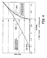
- An additional graph plotting airspeed versus impact pressure is shown in FIG. 4, and is used along with FIGS. 6A and 6B to illustrate a method of the present invention.
- FIG. 3 shown is a block diagram illustrating an embodiment of air data system 20 in accordance with one more specific embodiments of the invention.
- the more specific embodiment illustrated in FIG. 3 is, however, provided only as an example. Air data systems illustrating components other than those shown in FIG. 3 also fall within the scope of the present invention.
- air data system 20 includes pitot-static probes 22-1 and 22-2, for example mounted on opposite sides of the forward end of helicopter 10. While in some embodiments a single pitot-static probe 22 can be used, two or more pitot-static probes are typically used for redundancy and other purposes.
- the pitot-static probes 22-1 and 22-2 measure static pressure Ps and total pressure Pt.
- Air data system 20 also includes two ADCs 24-1 and 24-2, for redundancy purposes, and a flight control or mission computer 202.
- the air data computers 24-1 and 24-2 are pneumatically plumbed to the pitot-static probes.
- the air data computer measures these pressures using various pressure sensors.
- Each ADC receives at least one total pressure Pt and at least one differential static pressure Ps as an input.
- MFPs multi-function probes
- Smart Probes are used.
- the MFPs can be electrically coupled to the ADC instead of pneumatically.
- the illustrations of the invention represent both of these alternative embodiments.
- each pilot-static probe can include two separate static pressure sensing ports for differential static pressure measurement.
- the two static pressure sensing ports (and the pressures sensed by these ports) for each of probes 22-1 and 22-2 are labeled S1 and S2.
- the first static pressure sensing port S1 from probe 22-1 is pneumatically plumbed with the second static pressure sensing port S2 from probe 22-2
- the second static pressure sensing port S2 from probe 22-1 is pneumatically plumbed with the first static pressure sensing port S1 of probe 22-2.
- the static pressure sensing ports can be pneumatically connected in different ways, for example, with the S1 and S2 ports of each individual probe connected together.
- the various pressures can be electrically averaged or processed.
- ADCs 24-1 and 24-2 can also receive input from other input devices, for example from a temperature probe 201 mounted on the helicopter.
- the electronics in the ADCs 24-1 and 24-2 covert the pressures to analog signals, and then to digital signals.
- Embedded software in the ADCs uses the raw digital signals to filter the data and calculate various air data parameters.
- the ADCs 24-1 and 24-2 calculate impact (differential) pressure Qc by subtracting the static pressure Ps from the total pressure Pt.
- Each of ADCs 24-1 and 24-2 output its calculated data over a corresponding communications bus 204-1, 204-2, such as ARINC 429 or MIL-STD-1553B communication buses.
- Mission computer 202 uses this data in its own calculations, and transmits some, or all of it to the multi-function or cockpit display(s) 26, which display the information to the pilot(s) of the aircraft.
- a method of estimating airspeed of an aircraft during low airspeed conditions is disclosed.
- the method first includes measuring a negative impact pressure using a pitot-static probe on the aircraft.
- Measuring a negative impact pressure includes the steps necessary to calculate the negative impact pressure using other measured pressures.
- Using a pitot-static probe on the aircraft includes using one pitot-static probe, using multiple pitot-static probes in combination, and using separate total pressure measuring devices and static pressure measuring devices.
- the method includes estimating a non-zero airspeed of the aircraft as a function of the measured negative impact pressure.
- Negative impact pressures can be correlated directly to irspeeds of the aircraft, using a curve fit function based upon flight test data taken at known airspeeds for slow flight, take offs, and landings.
- conventional algorithms for calculating or estimating airspeed from impact pressure are not used until the measured impact pressure is a positive number, and in some embodiments, not until the measured impact pressure exceeds a non-zero positive number threshold in order to suppress the erroneous airspeed data calculated from the uncompensated and unfiltered measured dynamic pressure. While the impact pressure remains negative and below any threshold selected, the LAA algorithm is used to estimate the airspeed directly from the impact pressure.
- the negative impact pressure is correlated, using the same techniques, to a positive impact pressure.
- the correlated positive impact pressure can then be used in conventional algorithms for calculating or estimating the airspeed of the aircraft. Steps in a method of generating LAA coefficients are described below.
- flight test data needs to include the actual data recorded from the air data computer, as well as data recorded from the reference device (the device that is not affected by rotor or aircraft effects, such as the flight test boom, etc).
- This example uses airspeed to generate the Low Airspeed Assist coefficients in the following steps.
- the Low Airspeed Assist coefficients are used in curve fitting measured impact pressure to airspeed or to a corrected impact pressure, as is also discussed below.
- a threshold value at which point conventional airspeed as a function of impact pressure equations can be used. For example, if experiments show that calculated airspeed using actual measured impact pressure becomes accurate at some particular non-zero positive value, that value can be used as such a threshold.
- steps analogous to those described above can be used to generate a curve fit equation which relates uncorrected measured impact pressure to corrected impact pressure.
- negative impact pressure values result, using the equation, in positive corrected impact pressure values.
- conventional airspeed as a function of impact pressure equations can be used.
- multi-function pilot-static probes having processing circuitry in an electronics housing attached to the probe can be used to sense the static and total pressures.
- the processing circuitry attached to these probes can then perform some or all of the steps of the method.
- the multi-function probe can itself be some or all of an ADC with respect to implementation of the invention.
Landscapes
- Physics & Mathematics (AREA)
- General Physics & Mathematics (AREA)
- Engineering & Computer Science (AREA)
- Aviation & Aerospace Engineering (AREA)
- Measuring Fluid Pressure (AREA)
Abstract
Description
- The present invention relates to air data computers (ADCs) or systems, and algorithms implemented therein, for use in helicopters or other rotorcraft. More particularly, the present invention relates to a Low Airspeed Assist (LAA) method, and ADCs or systems implementing the same, to provide more accurate airspeed information in helicopters or other rotorcraft at low airspeeds.
- Air data systems on helicopters and other rotorcraft include one or more pitot-static probes, an air data computer connected to the pitot-static probe(s), and other sensors if desired. The pitot-static probe(s) are mounted toward the front end of the helicopter, and are used to sense or calculate total pressure Pt and static pressure Ps If the aircraft utilizes more than one pitot-static probe, Pt is the average total pressure and Ps is the average static pressure measurement. As is known in the art, impact pressure (also referred to as dynamic pressure and commonly denoted Qc) can be calculated by subtracting the static pressure Ps from the total pressure Pt. These pressure measurements are most accurate when the pitot-static probe is properly placed on the aircraft to minimize aerodynamic errors from the vehicle, and when the pitot-static probe is sensing pitot and static pressure in a pressure field created only by the forward velocity of the vehicle and is free of the rotor downwash effect seen during slow flight, take-offs, and landings.
- At low airspeeds, the impact pressure readings from the pitot-static probe(s) are affected by downwash from the main rotor into the static ports of the pitot-static probe(s), by high pressure fields beneath the rotor, and by the local pitch of the aircraft during takeoff. These effects cause the impact pressure reading to be less than the free stream impact pressure, thus resulting in negative values of impact pressure during such an event.
- Conventionally, the impact pressure Qc is calculated as indicated above, and then that impact pressure is converted to an airspeed using known techniques. Using conventional techniques, with a negative impact pressure, calculated airspeed will be zero even though the helicopter in fact has a non-zero airspeed. As the helicopter increases in airspeed, relative to the helicopter, the downwash angles back toward the rear of the aircraft. At some minimum airspeed for the particular helicopter and flight conditions, the downwash moves completely behind the pitot-static probe(s), allowing accurate pressure measurements of impact pressure for use in the airspeed calculation.
- During takeoffs and landings, it is important for estimated airspeeds to be readable and repeatable. Conventionally, measured helicopter airspeeds have only been accurate and repeatable when they have surpassed the minimum airspeed mentioned above, at which the downwash angles behind the pitot-static probe(s), relative to the helicopter. A minimum airspeed that is important to helicopter pilots is the Take Off Safety Speed (TOSS). The TOSS is the speed at which the aircraft will safely take to the air. This speed varies with aircraft, takeoff weight, air temperature, etc. An improved method of estimating helicopter airspeeds while the calculated impact pressure is still negative and the aircraft is accelerating through the Critical Decision Point (CDP - a point along the flight path that dictates the decision point on where to land, should landing be necessary) would be a significant improvement in the art.
- The present invention includes methods of calculating the airspeed of rotary wing aircraft at low airspeeds in which impact pressure readings from the pilot-static probe(s) are affected by downwash from the main rotor, by high pressure fields beneath the rotor, and/or by the local pitch of the aircraft during takeoff. When these effects cause the impact pressure reading to be less than the free stream impact pressure, thus resulting in negative values of measured or calculated impact pressure, the methods of the present invention can be used to estimate actual airspeed by estimating non-zero airspeed values as a function of the negative impact pressure. The present invention also includes air data computers and systems configured to implement the methods disclosed herein, and computer programs as may be recorded on a computer readable medium.
- The method of estimating airspeed of an aircraft during low airspeed conditions includes measuring a negative impact pressure using a pitot-static probe on the aircraft. Then, the method includes estimating a non-zero airspeed of the aircraft as a function of the measured negative impact pressure.
- In some embodiments, estimating the non-zero airspeed of the aircraft further comprises estimating the non-zero airspeed of the aircraft as a function of an impact pressure bias. The impact pressure bias is an uncorrected impact pressure when an actual airspeed of the aircraft is zero during a maneuver which results in a weight-on-wheels for the aircraft being zero.
- In some embodiments, estimating the non-zero airspeed of the aircraft further includes estimating the non-zero airspeed of the aircraft using a curve fit equation which relates negative impact pressure values directly to non-zero airspeed values.
- In other embodiments, estimating the non-zero airspeed of the aircraft further includes calculating a positive corrected impact pressure value as a function of the measured negative impact pressure value. Then, the non-zero airspeed of the aircraft is estimated as a function of the positive corrected impact pressure value.
-
- FIG. 1 is a diagrammatic side view of a helicopter in a low airspeed condition in which the pitot-static probe is in the rotor downwash.
- FIG. 2 is a graph illustrating measured impact pressure (dynamic pressure versus target airspeed during takeoff under one set of flight conditions for a particular helicopter.
- FIG. 3 is a block diagram illustrating an air data system in which a method of the present invention can be implemented.
- FIG. 4 is a graph illustrating flight test data verses reference airspeed.
- FIG. 5 is a block diagram illustrating a method of estimating airspeed of an aircraft in low airspeed conditions.
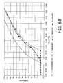
- FIGS. 6A and 6B are a table and a graph, respectively, which together illustrate steps of a method to calculate low airspeed assist coefficients in accordance with an example embodiment of the present invention.
-
- The present invention includes a Low Airspeed Assist (LAA) method and algorithm, and an air data computer (ADC) and system implementing the same, to provide more accurate airspeed information in helicopters or other rotorcraft at low airspeeds. For example, the present invention can be used at airspeeds below the Critical Decision Point (CDP) and the Take Off Safety Speed (TOSS). The algorithm uses helicopter flight test data from actual performed takeoffs and landings (Rolling, CAT A, CAT Vertical, etc.) and from level flight at varied airspeeds, which is compared with a reference airspeed. The reference airspeed can be obtained, for example, using a trailing bomb (an air data probe suspended from the aircraft such that it is deployed outside the aircraft's airstream), calibrated nose boom, or a fixed airspeed course for the level flight constant airspeed tests. For the take off and landing flight tests it is common to use on-field radar or the helicopter nose boom for the airspeed or Qc reference. The effected impact pressure Qc (also known as dynamic pressure) is fit to the results in the flight test airspeed. In embodiments described herein, the algorithm then uses polynomial curve fit, for example between 2nd order and 6th order polynomial fit, to convert the resulting impact pressure data, including negative values, directly to airspeeds. Higher order polynomial curve fits can also be used.
- FIG. 1 is a diagrammatic side view of a helicopter (or other rotorcraft) 10 during a low airspeed situation, such as a takeoff, landing, slow level flight, or slow flight in steep climb (for example greater than 1,500 ft/min).
Helicopter 10 includes abody 12 and arotor 14. Thehelicopter 10 also includes anair data system 20 having at least one pitot-static probe 22 connected to anADC 24. A multi-function display (MFD) 26 is coupled to theADC 24 and displays airspeed and other necessary information to the pilot ofhelicopter 10. Pilot-static probe 22 can be of a type known in the art which includes static pressure sensing ports 23 (due to the illustrated view, only one static port shown in FIG. 1) on opposite sides of the probe, and a totalpressure sensing port 25 at a front end of the probe. Typically, more than one pitot-static probe 22 (for example 22-1 and 22-2 shown in FIG. 3) are used in anair data system 20. - Also as is known in the art,
ADC 24 utilizes the sensed total pressure Pt and the sensed or calculated static pressure Ps (typically where Ps is the average pressure between the two static pressure sensing ports 23) to calculate the impact pressure Qc. At airspeeds above some minimum airspeed which is aircraft and flight condition dependent, ADC 24 also uses conventional techniques to calculate or estimate the airspeed as a function of the impact pressure Qc. - Consider for the moment that
helicopter 10 is in a takeoff situation. Ashelicopter 10 adds power in preparation for an aggressive take-off, a positive pressure is applied to thestatic ports 23 of the pitot-static probe 22 due to downwash (represented by arrows 30) from themain rotor 14. FIG. 2 is a graph plotting impact pressure Qc (represented by curve 102) as a function of indicated airspeed (IAS) for one particular example helicopter and set of flight conditions. As can be seen in FIG. 2, due to thedownwash 30 from themain rotor 14, the calculated impact pressure Qc is in fact negative until the helicopter reaches a sufficient airspeed. -
Curve 104 in FIG. 2 illustrates the indicated airspeed when estimated or calculated using the impact pressure Qc obtained from the pressures sensed by pitot-static probe 22.Curve 106 illustrates the indicated airspeed for the same helicopter as calculated using a "cleaner" impact pressure. This "cleaner" impact pressure can be obtained, for example, using a pitot-static probe mounted on a boom 28 (FIG. 1) forward of the helicopter by a distance sufficient to place the probe outside of therotor downwash 30 during these low airspeed operating conditions. As can be seen in FIG. 2 bycomparing curve - As the helicopter begins to accelerate and the rotor downwash begins to move aft of the aircraft, the impact pressure Qc begins to increase as can be seen in
curve 102 of FIG. 2. As the helicopter accelerates in this example through about 30 knots (kts), a positive impact pressure is sensed by the side mounted pitot-static probes 22, and an airspeed indication is now obtainable, although typically with significant error until the rotor downwash is well aft of the vehicle. For instance, in this example, while a positive impact pressure is calculated using the pitot-static probe data when the aircraft's actual airspeed is about 30 knots, the airspeed at which significant error is no longer present in the impact pressure measurement is approximately 45 knots. This airspeed is aircraft and flight condition dependent. - It is important to note that, to obtain the measured impact pressure, a digital filter should be used in order to smooth the data before computations are performed. The data illustrated in FIG. 2 is post filtered data. While any of a wide number of digital filters can be used to filter the data, the filter used to obtain the best results during research of the invention was a Sth order IIR Inverse Tschebyscheff Digital filter. This filtering can be implemented in processing circuitry within
ADC 24, for example. An additional graph plotting airspeed versus impact pressure is shown in FIG. 4, and is used along with FIGS. 6A and 6B to illustrate a method of the present invention. - Referring now to FIG. 3, shown is a block diagram illustrating an embodiment of
air data system 20 in accordance with one more specific embodiments of the invention. The more specific embodiment illustrated in FIG. 3 is, however, provided only as an example. Air data systems illustrating components other than those shown in FIG. 3 also fall within the scope of the present invention. - As illustrated,
air data system 20 includes pitot-static probes 22-1 and 22-2, for example mounted on opposite sides of the forward end ofhelicopter 10. While in some embodiments a single pitot-static probe 22 can be used, two or more pitot-static probes are typically used for redundancy and other purposes. The pitot-static probes 22-1 and 22-2 measure static pressure Ps and total pressure Pt. -
Air data system 20 also includes two ADCs 24-1 and 24-2, for redundancy purposes, and a flight control ormission computer 202. The air data computers 24-1 and 24-2 are pneumatically plumbed to the pitot-static probes. The air data computer measures these pressures using various pressure sensors. Each ADC receives at least one total pressure Pt and at least one differential static pressure Ps as an input. In other embodiments, multi-function probes (MFPs) or Smart Probes are used. In these embodiments, the MFPs can be electrically coupled to the ADC instead of pneumatically. The illustrations of the invention represent both of these alternative embodiments. - As described above with reference to FIG. 1, each pilot-static probe can include two separate static pressure sensing ports for differential static pressure measurement. In FIG. 3, the two static pressure sensing ports (and the pressures sensed by these ports) for each of probes 22-1 and 22-2 are labeled S1 and S2. In one embodiment, the first static pressure sensing port S1 from probe 22-1 is pneumatically plumbed with the second static pressure sensing port S2 from probe 22-2, while the second static pressure sensing port S2 from probe 22-1 is pneumatically plumbed with the first static pressure sensing port S1 of probe 22-2. These two differential pressures are each plumbed to a different one of ADCs 24-1 and 24-2. However, in other embodiments, the static pressure sensing ports can be pneumatically connected in different ways, for example, with the S1 and S2 ports of each individual probe connected together. In embodiments using MFPs, instead of pneumatic plumbing, the various pressures can be electrically averaged or processed. ADCs 24-1 and 24-2 can also receive input from other input devices, for example from a
temperature probe 201 mounted on the helicopter. - The electronics in the ADCs 24-1 and 24-2 covert the pressures to analog signals, and then to digital signals. Embedded software in the ADCs uses the raw digital signals to filter the data and calculate various air data parameters. The ADCs 24-1 and 24-2 calculate impact (differential) pressure Qc by subtracting the static pressure Ps from the total pressure Pt. Each of ADCs 24-1 and 24-2 output its calculated data over a corresponding communications bus 204-1, 204-2, such as
ARINC 429 or MIL-STD-1553B communication buses.Mission computer 202 uses this data in its own calculations, and transmits some, or all of it to the multi-function or cockpit display(s) 26, which display the information to the pilot(s) of the aircraft. - In accordance with embodiments of the present invention, a method of estimating airspeed of an aircraft during low airspeed conditions is disclosed. As is illustrated in
step 505 of the flow diagram 500 shown in FIG. 5, the method first includes measuring a negative impact pressure using a pitot-static probe on the aircraft. Measuring a negative impact pressure includes the steps necessary to calculate the negative impact pressure using other measured pressures. Using a pitot-static probe on the aircraft includes using one pitot-static probe, using multiple pitot-static probes in combination, and using separate total pressure measuring devices and static pressure measuring devices. - Next, as illustrated at
step 510 of FIG. 5, the method includes estimating a non-zero airspeed of the aircraft as a function of the measured negative impact pressure. This can be done in a number of different ways which fall within the scope of the invention. Negative impact pressures can be correlated directly to irspeeds of the aircraft, using a curve fit function based upon flight test data taken at known airspeeds for slow flight, take offs, and landings. Using this technique, conventional algorithms for calculating or estimating airspeed from impact pressure are not used until the measured impact pressure is a positive number, and in some embodiments, not until the measured impact pressure exceeds a non-zero positive number threshold in order to suppress the erroneous airspeed data calculated from the uncompensated and unfiltered measured dynamic pressure. While the impact pressure remains negative and below any threshold selected, the LAA algorithm is used to estimate the airspeed directly from the impact pressure. - In other embodiments, the negative impact pressure is correlated, using the same techniques, to a positive impact pressure. The correlated positive impact pressure can then be used in conventional algorithms for calculating or estimating the airspeed of the aircraft. Steps in a method of generating LAA coefficients are described below.
- The following steps assume that sufficient flight test data has been acquired in order to provide a representative, or average, data set with which to generate the LAA coefficients for calculating airspeed during conditions in which measured impact pressure is negative. Various flight test methods can be used (fixed airspeed course, trailing airspeed bomb, flight test nose boom, etc.) to collect airspeed (IAS) and impact pressure (Qc) data during low airspeed maneuvers such as takeoffs, landings, hover, ground taxi, and low speed forward flight. The flight test data needs to include the actual data recorded from the air data computer, as well as data recorded from the reference device (the device that is not affected by rotor or aircraft effects, such as the flight test boom, etc). Also, note that since airspeed is calculated from impact pressure using a standard method, this method can be applied to both airspeed and impact pressure data. This example uses airspeed to generate the Low Airspeed Assist coefficients in the following steps. The Low Airspeed Assist coefficients are used in curve fitting measured impact pressure to airspeed or to a corrected impact pressure, as is also discussed below.
- 1) Once the flight test data is collected,
determine the uncorrected airspeed (or impact
pressure in the alternative embodiment) as measured
from the
air data computer 24. The uncorrected airspeed, which is the airspeed calculated using conventional techniques during these low airspeed conditions, is illustrated in the second column of the table shown in FIG. 6A. It is also illustrated in the corresponding curve of the graph in FIG. 6B which plots airspeed (IAS) versus impact pressure (Qc). In the alternative embodiments in which uncorrected impact pressure Qc is to be curve fit, instead of the uncorrected airspeed, the data in the first column of the FIG. 6A table would be used. A corresponding curve isn't shown in the graph of FIG. 6B for uncorrected impact pressure. - 2) Evaluate the uncorrected impact pressure point where the actual airspeed was zero and the corresponding negative Qc is most negative, either in a hover or at the start of a takeoff when the weight-on-wheels for the aircraft is zero (FIG. 4). This uncorrected impact pressure reading is the Qc bias. In the following example the Qc bias was - 0.2067 inches of Mercury (inHg). This Qc bias is then subtracted from the uncorrected impact pressure to calculate biased impact pressure (FIG. 6A, Step 2-shown in the fourth column).
- 3) Next, evaluate the actual airspeed (or impact pressure) from the reference measurement. Plot the reference airspeed against the biased impact pressure to yield the target airspeed. This is illustrated in the fifth column (step 3) of the table shown in FIG. 6A, and in the corresponding target airspeed curve in the graph of FIG. 6B. The target airspeed is the airspeed that the air data computer should have been reading if there were no rotor downwash effects. An appropriate curve fit is applied to fit the target airspeed versus biased impact pressure. Depending on the required accuracy, a polynomial fit can be generated, as in this example (Figure 6A, Step 3), or any other mathematical estimations, such as a logarithmic fit, an exponential fit, etc. The result is a set of curve fit coefficients.
- 4) Finally, apply the new curve fit coefficients
to the LAA equation, and calculate the new LAA
airspeed using the uncorrected impact pressure (FIG
6A, step 4-shown in the sixth column). In this
example, the 6th order polynomial curve fit was used
as shown in
Equation 1.where,
IAS is the indicated airspeed;
QcBias is the Qc bias as determined above; and
A-G are the curve fit coefficients as determined above.
Using a polynomial (or other) curve fit such as the
one shown in -
- positive, and optionally until it exceeds a threshold value, at which point conventional airspeed as a function of impact pressure equations can be used. For example, if experiments show that calculated airspeed using actual measured impact pressure becomes accurate at some particular non-zero positive value, that value can be used as such a threshold.
- As mentioned above, in other embodiments, steps analogous to those described above can be used to generate a curve fit equation which relates uncorrected measured impact pressure to corrected impact pressure. Thus, negative impact pressure values result, using the equation, in positive corrected impact pressure values. Then, using the corrected impact pressure values in place of the measured impact pressure values, conventional airspeed as a function of impact pressure equations can be used.
- Although the present invention has been described with reference to preferred embodiments, workers skilled in the art will recognize that changes may be made in form and detail without departing from the scope of the invention. For example, while the present invention is described as a method of estimating airspeed of an aircraft during low airspeed conditions, the phrase "low airspeed conditions" is intended to represent any flight condition or maneuver of a rotorcraft which results in a negative impact pressure being measured or calculated.
- Further, while the present invention is described as a method implemented in an ADC or system using pressures sensed by one or more pitot-static probes, some or all of the method can be implemented elsewhere. For example, multi-function pilot-static probes having processing circuitry in an electronics housing attached to the probe can be used to sense the static and total pressures. The processing circuitry attached to these probes can then perform some or all of the steps of the method. In other words, the multi-function probe can itself be some or all of an ADC with respect to implementation of the invention.
Claims (16)
- A method of estimating airspeed of an aircraft during low airspeed conditions, the method comprising:measuring a negative impact pressure using at least one pitot-static probe on the aircraft; andestimating a non-zero airspeed of the aircraft as a function of the measured negative impact pressure.
- The method of claim 1, wherein estimating the non-zero airspeed of the aircraft further comprises estimating the non-zero airspeed of the aircraft as a function of an impact pressure bias.
- The method of claim 2, wherein the impact pressure bias is an uncorrected impact pressure when an actual airspeed of the aircraft is zero.
- The method of claim 3, wherein the impact pressure bias is an uncorrected impact pressure when the actual airspeed of the aircraft is zero during a manoeuvre which results in a weight-on-wheels for the aircraft being zero.
- The method of any of claims 2 to 4, wherein estimating the non-zero airspeed of the aircraft further comprises estimating the non-zero airspeed of the aircraft using a curve fit equation which relates negative impact pressure values directly to non-zero airspeed values.
- The method of any preceding claim, wherein estimating the non-zero airspeed of the aircraft further comprises:calculating a positive corrected impact pressure value as a function of the measured negative impact pressure value; andestimating the non-zero airspeed of the aircraft as a function of the positive corrected impact pressure value.
- An air data computer for a rotorcraft operable to receive a sensed static pressure and a sensed total pressure, to determine impact pressure from the sensed static pressure and total pressure and to estimate non-zero airspeeds of the aircraft as a function of determined negative impact pressures.
- The air data computer of claim 7, further operable to estimate the non-zero airspeeds of the aircraft as a function of an impact pressure bias.
- The air data computer of claim 8, herein the impact pressure bias is an uncorrected impact pressure when an actual airspeed of the aircraft is zero.
- The air data computer of claim 9, wherein the impact pressure bias is an uncorrected impact pressure when the actual airspeed of the aircraft is zero during a manoeuvre which results in a weight-on-wheels for the aircraft being zero.
- The air data computer of any of claims 8 to 10, further operable to estimate the non-zero airspeed of the aircraft using a curve fit equation which relates negative impact pressure values directly to non-zero airspeed values.
- The air data computer of any of claims 7 to 11, further operable to estimate the non-zero airspeeds of the aircraft by calculating a positive corrected impact pressure value as a function of the measured negative impact pressure value, and estimating the non-zero airspeed of the aircraft as a function of the positive corrected impact pressure value.
- An air data system for a rotorcraft, the air data system comprising the air data computer of any of claims 7 to 12 and means for sensing the static pressure and the total pressure.
- The air data system of claim 13, and further comprising at least one pitot-static probe providing the means for sensing static pressure and total pressure.
- A computer program comprising program instructions that, when loaded into an air data computer, provide the air data computer as defined by any of claims 7 to 12.
- A computer readable medium having the computer program of claim 15 recorded thereon.
Applications Claiming Priority (2)
| Application Number | Priority Date | Filing Date | Title |
|---|---|---|---|
| US396165 | 2003-03-25 | ||
| US10/396,165 US7127335B2 (en) | 2003-03-25 | 2003-03-25 | Low airspeed assist algorithm for air data computer applications |
Publications (2)
| Publication Number | Publication Date |
|---|---|
| EP1462806A1 true EP1462806A1 (en) | 2004-09-29 |
| EP1462806B1 EP1462806B1 (en) | 2011-01-26 |
Family
ID=32824952
Family Applications (1)
| Application Number | Title | Priority Date | Filing Date |
|---|---|---|---|
| EP04251744A Expired - Fee Related EP1462806B1 (en) | 2003-03-25 | 2004-03-25 | Determination of airspeed from negative impact pressure |
Country Status (6)
| Country | Link |
|---|---|
| US (1) | US7127335B2 (en) |
| EP (1) | EP1462806B1 (en) |
| BR (1) | BRPI0400781A (en) |
| CA (1) | CA2462080A1 (en) |
| DE (1) | DE602004031169D1 (en) |
| IL (1) | IL161044A (en) |
Cited By (5)
| Publication number | Priority date | Publication date | Assignee | Title |
|---|---|---|---|---|
| FR3020799A1 (en) * | 2014-05-12 | 2015-11-13 | Airbus Helicopters | GIRAVION EQUIPPED WITH ANEMOMETER PLACED AT THE TOP OF A REAR DRIFT OF THE GIRAVION |
| EP2955106A1 (en) * | 2014-06-10 | 2015-12-16 | Sikorsky Aircraft Corporation | Rotorcraft flight parameter estimation |
| EP3546347A1 (en) * | 2018-03-29 | 2019-10-02 | CAE Inc. | Method and system for determining an air recirculation effect from an obstacle on a main rotor induced velocity of a simulated rotorcraft |
| US10909875B2 (en) | 2018-03-29 | 2021-02-02 | Cae Inc. | Method and system for determining a recirculation effect from an obstacle on a main rotor induced velocity of a simulated rotorcraft |
| CN112977869A (en) * | 2021-02-25 | 2021-06-18 | 成都凯天电子股份有限公司 | Helicopter atmospheric data system rotor wing down-wash influence correction method |
Families Citing this family (5)
| Publication number | Priority date | Publication date | Assignee | Title |
|---|---|---|---|---|
| US9285387B2 (en) * | 2009-12-14 | 2016-03-15 | The United States Of America As Represented By The Administrator Of The National Aeronautics And Space Administration | In-flight pitot-static calibration |
| ES2394558B1 (en) * | 2010-01-18 | 2013-12-12 | Eads Construcciones Aeronáuticas, S.A. | PROBE SUPPORT DEVICE. |
| FR2959316B1 (en) * | 2010-04-21 | 2012-05-18 | Airbus Operations Sas | METHOD AND DEVICE FOR AUTOMATICALLY ESTIMATING AIR SPEED OF AN AIRCRAFT |
| US10101356B2 (en) * | 2014-02-19 | 2018-10-16 | Eit Llc | Instrument and method for measuring low indicated air speed |
| CN111498095A (en) * | 2019-01-02 | 2020-08-07 | 贝尔德事隆公司 | System and method for controlling a rotorcraft |
Citations (4)
| Publication number | Priority date | Publication date | Assignee | Title |
|---|---|---|---|---|
| US4702106A (en) * | 1985-06-11 | 1987-10-27 | Litef Gmbh | Method for determining the horizontal airspeed of helicopters in low speed ranges |
| US5349347A (en) | 1993-03-29 | 1994-09-20 | Alliedsignal Inc. | Method and apparatus for correcting dynamically induced errors in static pressure, airspeed and airspeed rate |
| JPH10227808A (en) * | 1997-02-17 | 1998-08-25 | Commuter Herikoputa Senshin Gijutsu Kenkyusho:Kk | Airspeed measuring system for rotorcraft |
| US6205376B1 (en) | 1999-06-22 | 2001-03-20 | Rockwell Collins, Inc. | Blocked pitot-static monitor |
Family Cites Families (13)
| Publication number | Priority date | Publication date | Assignee | Title |
|---|---|---|---|---|
| US4801110A (en) * | 1987-12-21 | 1989-01-31 | Honeywell Inc. | Approach to hover control system for helicopters |
| DE69024958T2 (en) * | 1990-10-25 | 1996-05-30 | Boeing Co | Air speed control system for aircraft propulsion regulators |
| US5457630A (en) * | 1992-11-18 | 1995-10-10 | Aers/Midwest, Inc. | System for onboard lift analysis and apparatus therefor |
| US5616861A (en) * | 1995-06-07 | 1997-04-01 | Rosemount Aerospace Inc. | Three pressure pseudo -Δ-P sensor for use with three pressure air data probe |
| US5901272A (en) * | 1996-10-24 | 1999-05-04 | The United States Of America As Represented By The Secretary Of The Navy | Neural network based helicopter low airspeed indicator |
| RU2157980C2 (en) * | 1997-01-28 | 2000-10-20 | Центральный аэродинамический институт им. проф. Н.Е. Жуковского | Fuselage pitot-static tube with a strut |
| US7011498B2 (en) * | 1998-04-03 | 2006-03-14 | Athena Technologies, Inc. | Optimization method for power generation systems |
| US6561020B2 (en) * | 2001-05-08 | 2003-05-13 | Rosemount Aerospace Inc. | Method to calculate sideslip angle and correct static pressure for sideslip effects using inertial information |
| US6604029B2 (en) * | 2001-05-08 | 2003-08-05 | Rosemount Aerospace Inc. | Multi-function air data probes using neural network for sideslip compensation |
| US6609421B2 (en) * | 2001-05-08 | 2003-08-26 | Rosemount Aerospace Inc. | Sideslip correction for a multi-function three probe air data system |
| US6531967B2 (en) * | 2001-05-16 | 2003-03-11 | Robert S. Djorup | Aircraft disturbed air direct sensing system |
| US6761057B2 (en) * | 2001-09-13 | 2004-07-13 | Rosemount Aerospace Inc. | Error detection and fault isolation for multi-function air data probes and systems |
| US6688182B2 (en) * | 2002-01-31 | 2004-02-10 | Kulite Semiconductor Products, Inc. | Static pitot transducer |
-
2003
- 2003-03-25 US US10/396,165 patent/US7127335B2/en not_active Expired - Lifetime
-
2004
- 2004-03-24 IL IL161044A patent/IL161044A/en active IP Right Grant
- 2004-03-24 CA CA002462080A patent/CA2462080A1/en not_active Abandoned
- 2004-03-25 EP EP04251744A patent/EP1462806B1/en not_active Expired - Fee Related
- 2004-03-25 BR BR0400781-6A patent/BRPI0400781A/en not_active Application Discontinuation
- 2004-03-25 DE DE602004031169T patent/DE602004031169D1/en not_active Expired - Lifetime
Patent Citations (4)
| Publication number | Priority date | Publication date | Assignee | Title |
|---|---|---|---|---|
| US4702106A (en) * | 1985-06-11 | 1987-10-27 | Litef Gmbh | Method for determining the horizontal airspeed of helicopters in low speed ranges |
| US5349347A (en) | 1993-03-29 | 1994-09-20 | Alliedsignal Inc. | Method and apparatus for correcting dynamically induced errors in static pressure, airspeed and airspeed rate |
| JPH10227808A (en) * | 1997-02-17 | 1998-08-25 | Commuter Herikoputa Senshin Gijutsu Kenkyusho:Kk | Airspeed measuring system for rotorcraft |
| US6205376B1 (en) | 1999-06-22 | 2001-03-20 | Rockwell Collins, Inc. | Blocked pitot-static monitor |
Non-Patent Citations (1)
| Title |
|---|
| PATENT ABSTRACTS OF JAPAN vol. 1998, no. 13 30 November 1998 (1998-11-30) * |
Cited By (11)
| Publication number | Priority date | Publication date | Assignee | Title |
|---|---|---|---|---|
| FR3020799A1 (en) * | 2014-05-12 | 2015-11-13 | Airbus Helicopters | GIRAVION EQUIPPED WITH ANEMOMETER PLACED AT THE TOP OF A REAR DRIFT OF THE GIRAVION |
| EP2944572A1 (en) | 2014-05-12 | 2015-11-18 | Airbus Helicopters | Rotorcraft provided with an anemometer located at the top of a rear stabiliser of the rotorcraft |
| CN105083572A (en) * | 2014-05-12 | 2015-11-25 | 空客直升机 | Rotorcraft equipped with an anemometer placed at the peak of a rear stabilizer on the rotorcraft |
| US9415881B2 (en) | 2014-05-12 | 2016-08-16 | Airbus Helicopters | Rotorcraft having an airspeed sensor located at the top of a tail fin of the rotorcraft |
| CN105083572B (en) * | 2014-05-12 | 2017-08-04 | 空客直升机 | Gyroplane with the airspeed sensor at the top of gyroplane fin |
| EP2955106A1 (en) * | 2014-06-10 | 2015-12-16 | Sikorsky Aircraft Corporation | Rotorcraft flight parameter estimation |
| US9506945B2 (en) | 2014-06-10 | 2016-11-29 | Sikorsky Aircraft Corporation | Rotorcraft flight parameter estimation |
| EP3546347A1 (en) * | 2018-03-29 | 2019-10-02 | CAE Inc. | Method and system for determining an air recirculation effect from an obstacle on a main rotor induced velocity of a simulated rotorcraft |
| US10909875B2 (en) | 2018-03-29 | 2021-02-02 | Cae Inc. | Method and system for determining a recirculation effect from an obstacle on a main rotor induced velocity of a simulated rotorcraft |
| CN112977869A (en) * | 2021-02-25 | 2021-06-18 | 成都凯天电子股份有限公司 | Helicopter atmospheric data system rotor wing down-wash influence correction method |
| CN112977869B (en) * | 2021-02-25 | 2022-11-01 | 成都凯天电子股份有限公司 | Helicopter atmospheric data system rotor wing down-wash influence correction method |
Also Published As
| Publication number | Publication date |
|---|---|
| US7127335B2 (en) | 2006-10-24 |
| BRPI0400781A (en) | 2005-02-09 |
| IL161044A0 (en) | 2004-08-31 |
| IL161044A (en) | 2008-11-03 |
| CA2462080A1 (en) | 2004-09-25 |
| EP1462806B1 (en) | 2011-01-26 |
| DE602004031169D1 (en) | 2011-03-10 |
| US20040193333A1 (en) | 2004-09-30 |
Similar Documents
| Publication | Publication Date | Title |
|---|---|---|
| US10006928B1 (en) | Airspeed determination for aircraft | |
| EP1256812B1 (en) | Sideslip correction for a multi-function three probe air data system | |
| US8849479B2 (en) | Method and device for automatically estimating an airspeed of an aircraft | |
| US7480548B2 (en) | High-altitude capable wide velocity range flight velocity vector measurement probe and measurement system | |
| EP2117926B1 (en) | Ice rate meter with virtual aspiration | |
| EP2434296B1 (en) | Airspeed sensing system for an aircraft | |
| US6216064B1 (en) | Method and apparatus for determining altitude | |
| EP1237005B1 (en) | Integrated flight management system | |
| EP0082663B1 (en) | Takeoff weight computer apparatus for aircraft | |
| US6205376B1 (en) | Blocked pitot-static monitor | |
| CN104931007B (en) | Method and device for automatically estimating parameters relating to the flight of an aircraft | |
| US20040206854A1 (en) | Method and apparatus for detecting conditions conducive to ice formation | |
| EP1462806B1 (en) | Determination of airspeed from negative impact pressure | |
| US7561945B2 (en) | Sum integration estimating of the vertical speed for a rotary wing aircraft | |
| US20110264308A1 (en) | Method And Device For Automatically Estimating An Air Speed Of An Aircraft | |
| US20170284856A1 (en) | Aircraft weight estimation | |
| GB2088310A (en) | Angle of attack based pitch generator and head up display | |
| EP3688437A1 (en) | Method, system, and graphical indicator for providing a lateral center of gravity of an aircraft | |
| EP1058816B1 (en) | Method and apparatus for determining altitude | |
| KR101972130B1 (en) | Appartus and method for determine air mass flow rate of supersonic intake | |
| EP4078189A1 (en) | Monitoring a speed determination system | |
| US20070295078A1 (en) | System for measuring an airflow angle at the wingtip of an aircraft | |
| US20220355948A1 (en) | Computation of aircraft airspeed by inclusion of static air temperature | |
| Hassenpflug et al. | A new method of analytical evaluation of helicopter true airspeed |
Legal Events
| Date | Code | Title | Description |
|---|---|---|---|
| PUAI | Public reference made under article 153(3) epc to a published international application that has entered the european phase |
Free format text: ORIGINAL CODE: 0009012 |
|
| AK | Designated contracting states |
Kind code of ref document: A1 Designated state(s): AT BE BG CH CY CZ DE DK EE ES FI FR GB GR HU IE IT LI LU MC NL PL PT RO SE SI SK TR |
|
| AX | Request for extension of the european patent |
Extension state: AL HR LT LV MK |
|
| 17P | Request for examination filed |
Effective date: 20050119 |
|
| AKX | Designation fees paid |
Designated state(s): DE FR GB IT |
|
| 17Q | First examination report despatched |
Effective date: 20080616 |
|
| GRAP | Despatch of communication of intention to grant a patent |
Free format text: ORIGINAL CODE: EPIDOSNIGR1 |
|
| GRAS | Grant fee paid |
Free format text: ORIGINAL CODE: EPIDOSNIGR3 |
|
| GRAA | (expected) grant |
Free format text: ORIGINAL CODE: 0009210 |
|
| AK | Designated contracting states |
Kind code of ref document: B1 Designated state(s): DE FR GB IT |
|
| REG | Reference to a national code |
Ref country code: GB Ref legal event code: FG4D |
|
| REF | Corresponds to: |
Ref document number: 602004031169 Country of ref document: DE Date of ref document: 20110310 Kind code of ref document: P |
|
| REG | Reference to a national code |
Ref country code: DE Ref legal event code: R096 Ref document number: 602004031169 Country of ref document: DE Effective date: 20110310 |
|
| PLBE | No opposition filed within time limit |
Free format text: ORIGINAL CODE: 0009261 |
|
| STAA | Information on the status of an ep patent application or granted ep patent |
Free format text: STATUS: NO OPPOSITION FILED WITHIN TIME LIMIT |
|
| 26N | No opposition filed |
Effective date: 20111027 |
|
| REG | Reference to a national code |
Ref country code: DE Ref legal event code: R097 Ref document number: 602004031169 Country of ref document: DE Effective date: 20111027 |
|
| REG | Reference to a national code |
Ref country code: FR Ref legal event code: PLFP Year of fee payment: 13 |
|
| REG | Reference to a national code |
Ref country code: FR Ref legal event code: PLFP Year of fee payment: 14 |
|
| REG | Reference to a national code |
Ref country code: FR Ref legal event code: PLFP Year of fee payment: 15 |
|
| PGFP | Annual fee paid to national office [announced via postgrant information from national office to epo] |
Ref country code: DE Payment date: 20200218 Year of fee payment: 17 Ref country code: IT Payment date: 20200218 Year of fee payment: 17 Ref country code: GB Payment date: 20200221 Year of fee payment: 17 |
|
| PGFP | Annual fee paid to national office [announced via postgrant information from national office to epo] |
Ref country code: FR Payment date: 20200220 Year of fee payment: 17 |
|
| REG | Reference to a national code |
Ref country code: DE Ref legal event code: R119 Ref document number: 602004031169 Country of ref document: DE |
|
| GBPC | Gb: european patent ceased through non-payment of renewal fee |
Effective date: 20210325 |
|
| PG25 | Lapsed in a contracting state [announced via postgrant information from national office to epo] |
Ref country code: GB Free format text: LAPSE BECAUSE OF NON-PAYMENT OF DUE FEES Effective date: 20210325 Ref country code: FR Free format text: LAPSE BECAUSE OF NON-PAYMENT OF DUE FEES Effective date: 20210331 Ref country code: DE Free format text: LAPSE BECAUSE OF NON-PAYMENT OF DUE FEES Effective date: 20211001 |
|
| PG25 | Lapsed in a contracting state [announced via postgrant information from national office to epo] |
Ref country code: IT Free format text: LAPSE BECAUSE OF NON-PAYMENT OF DUE FEES Effective date: 20210325 |