EP1464351A2 - Low-profile automatic injection device with self-emptying reservoir - Google Patents
Low-profile automatic injection device with self-emptying reservoir Download PDFInfo
- Publication number
- EP1464351A2 EP1464351A2 EP04011624A EP04011624A EP1464351A2 EP 1464351 A2 EP1464351 A2 EP 1464351A2 EP 04011624 A EP04011624 A EP 04011624A EP 04011624 A EP04011624 A EP 04011624A EP 1464351 A2 EP1464351 A2 EP 1464351A2
- Authority
- EP
- European Patent Office
- Prior art keywords
- reservoir
- therapeutic preparation
- housing
- needle
- liquid therapeutic
- Prior art date
- Legal status (The legal status is an assumption and is not a legal conclusion. Google has not performed a legal analysis and makes no representation as to the accuracy of the status listed.)
- Granted
Links
Images


Classifications
-
- A—HUMAN NECESSITIES
- A61—MEDICAL OR VETERINARY SCIENCE; HYGIENE
- A61M—DEVICES FOR INTRODUCING MEDIA INTO, OR ONTO, THE BODY; DEVICES FOR TRANSDUCING BODY MEDIA OR FOR TAKING MEDIA FROM THE BODY; DEVICES FOR PRODUCING OR ENDING SLEEP OR STUPOR
- A61M5/00—Devices for bringing media into the body in a subcutaneous, intra-vascular or intramuscular way; Accessories therefor, e.g. filling or cleaning devices, arm-rests
- A61M5/14—Infusion devices, e.g. infusing by gravity; Blood infusion; Accessories therefor
- A61M5/142—Pressure infusion, e.g. using pumps
- A61M5/145—Pressure infusion, e.g. using pumps using pressurised reservoirs, e.g. pressurised by means of pistons
- A61M5/14586—Pressure infusion, e.g. using pumps using pressurised reservoirs, e.g. pressurised by means of pistons pressurised by means of a flexible diaphragm
-
- A—HUMAN NECESSITIES
- A61—MEDICAL OR VETERINARY SCIENCE; HYGIENE
- A61M—DEVICES FOR INTRODUCING MEDIA INTO, OR ONTO, THE BODY; DEVICES FOR TRANSDUCING BODY MEDIA OR FOR TAKING MEDIA FROM THE BODY; DEVICES FOR PRODUCING OR ENDING SLEEP OR STUPOR
- A61M5/00—Devices for bringing media into the body in a subcutaneous, intra-vascular or intramuscular way; Accessories therefor, e.g. filling or cleaning devices, arm-rests
- A61M5/14—Infusion devices, e.g. infusing by gravity; Blood infusion; Accessories therefor
- A61M5/142—Pressure infusion, e.g. using pumps
- A61M5/14244—Pressure infusion, e.g. using pumps adapted to be carried by the patient, e.g. portable on the body
- A61M5/14248—Pressure infusion, e.g. using pumps adapted to be carried by the patient, e.g. portable on the body of the skin patch type
- A61M2005/14252—Pressure infusion, e.g. using pumps adapted to be carried by the patient, e.g. portable on the body of the skin patch type with needle insertion means
-
- A—HUMAN NECESSITIES
- A61—MEDICAL OR VETERINARY SCIENCE; HYGIENE
- A61M—DEVICES FOR INTRODUCING MEDIA INTO, OR ONTO, THE BODY; DEVICES FOR TRANSDUCING BODY MEDIA OR FOR TAKING MEDIA FROM THE BODY; DEVICES FOR PRODUCING OR ENDING SLEEP OR STUPOR
- A61M5/00—Devices for bringing media into the body in a subcutaneous, intra-vascular or intramuscular way; Accessories therefor, e.g. filling or cleaning devices, arm-rests
- A61M5/14—Infusion devices, e.g. infusing by gravity; Blood infusion; Accessories therefor
- A61M5/142—Pressure infusion, e.g. using pumps
- A61M5/14244—Pressure infusion, e.g. using pumps adapted to be carried by the patient, e.g. portable on the body
- A61M5/14248—Pressure infusion, e.g. using pumps adapted to be carried by the patient, e.g. portable on the body of the skin patch type
- A61M2005/1426—Pressure infusion, e.g. using pumps adapted to be carried by the patient, e.g. portable on the body of the skin patch type with means for preventing access to the needle after use
Definitions
- the present invention relates generally to a device for delivering a liquid therapeutic preparation into the body of a patient by injection into or though the patient's skin. More particularly, the invention relates to a low-profile automatic injection device that can be worn inconspicuously under the clothing of a patient to allow a liquid therapeutic preparation (such as insulin) to be administered over an extended period of time, and that incorporates a self-emptying reservoir to eliminate the need for a pump or other type of discharge device.
- a liquid therapeutic preparation such as insulin
- the devices disclosed in the aforementioned patents generally employ movable ampoules, pistons or other complex arrangements which are somewhat difficult to manufacture.
- the design of these devices generally requires that the reservoir be positioned above the needle driving mechanism, which results in a device of considerable height. This is not necessarily a problem when the drug solution is to be injected as a bolus at one discrete time, as most of these devices are designed to do, but it is a distinct disadvantage when the drug solution is to be infused into the patient over an extended period of time.
- the injection device may have to be held in contact with the patient's skin (e.g., by tape or an adhesive) for several hours or more, and this is difficult to achieve when the device has a large height dimension.
- Another class of devices includes those which are capable of gradually infusing a liquid therapeutic preparation into the skin of a patient. In some cases, these devices are small enough (both in height and in overall size) to allow them to be "worn" by an ambulatory patient while the liquid therapeutic preparation is being infused into the patient. Examples of devices which fall in to this class include those disclosed in U.S. Patent Nos. 4,340,048 and 4,753,651, both to Eckenhoff, U.S. Patent No. 4,734,092, to Millerd, U.S. Patent No. 4,781,688, to Thoma et al., U.S. Patent No. 4,886,499, to Cirelli et al., U.S. Patent No. 5,656,032, to Kriesel et al., and PCT Publication Nos. WO 95/13838 and WO 97/21457, both to Elan Medical Technologies, Ltd.
- an automatic injection device that is small and has a low-profile configuration, allowing it to be conveniently handled and worn (preferably in an inconspicuous manner under the clothing) by an ambulatory patient.
- a need also exists for an automatic injection device which is capable of infusing a drug solution or other liquid therapeutic preparation into the skin of a patient over an extended period of time.
- an automatic injection device whose basic design allows it to be not only small and low in height, but also simple and inexpensive to manufacture.
- a device for delivering a liquid therapeutic preparation into the body of a patient by injection into or through the skin of the patient comprises a housing adapted to be held in contact with the patient's skin.
- a reservoir is disposed within the housing for containing a liquid therapeutic preparation to be administered.
- the reservoir includes a Belleville spring which exerts pressure on the liquid therapeutic preparation to discharge the liquid therapeutic preparation from the reservoir at a relatively constant rate.
- An injection needle is adapted to communicate with the reservoir and to project from the housing in order to inject the liquid therapeutic preparation into or through the skin of the patient.
- the device 20 includes a rigid external housing 21 that consists of an upper housing portion 22 and a lower housing portion 24.
- the housing portions 22 and 24 may be made of a suitable plastic material, such as polycarbonate, and are joined to each other along a horizontal seam 26.
- the plastic material used for the housing 21 is preferably opaque, but may be transparent or translucent if desired. When viewed from above or below, the housing 21 has an oblong shape with rounded ends, as shown.
- the forward end 28 of the housing 21 is closed, but the rear end 30 of the housing includes a horizontally-extending slot 32 (formed by a notch in the upper housing portion 22) which allows access to the interior of the housing.
- the slot 32 allows a pre-filled liquid reservoir or dose chamber to be installed in the housing 21 after the device 20 has been assembled.
- Horizontal, crescent-shaped cut-outs 34 and 36 are formed in the upper and lower portions 22 and 24 of the housing 21 at the rear end 30 thereof to allow the liquid reservoir to be fully inserted.
- the upper portion 22 of the housing is formed with a recessed area 38 in which a hole 40 is formed.
- the hole 40 is elongated in the lengthwise direction of the device 20, and accommodates a slide button 42 which is operated by the user.
- the top surface of the slide button 42 is ribbed in a direction perpendicular to the direction of button movement, as shown, to allow the user's finger to engage the button 42 without slipping.
- the button 42 is initially in the position shown in Fig. 1 and is moved rearwardly (i.e., in the direction toward the rear end 30 of the housing 21) by the user during operation of the device 20.
- movement of the button 42 causes an injection needle to project from the bottom of the housing 21 and also causes the liquid therapeutic preparation to begin to flow through the injection needle from the internal reservoir.
- the bottom surface of the housing is flat and carries a layer of pressure-sensitive adhesive 44 which allows the device 20 to be affixed to the skin of a patient.
- the tackiness of the adhesive layer 44 is sufficient to allow the device 20 to remain securely attached to the patient's body, but is weak enough to allow the device 20 to be removed from the skin after use without discomfort.
- a suitable adhesive which may be used for this purpose is available from 3M Company of St. Paul, Minnesota.
- the bottom surface of the housing 21 is roughened or textured to allow for better adhesion of the pressure-sensitive adhesive layer 44 to the plastic material of the housing.
- a release liner 46 made of coated paper or a thin sheet of plastic, covers the adhesive layer 44 prior to use of the device 20.
- the release liner 46 When the release liner 46 is removed, it uncovers not only the adhesive layer 44 but also a small round hole 48 that is formed through the bottom portion 24 of the housing near its forward end 28.
- the hole 48 serves as a needle aperture for allowing an injection needle to protrude from the bottom of the device 20 when the slide button 42 of Fig. 1 is actuated, as will be described in detail below.
- the automatic injection device 20 of Figs. 1 and 2 is approximately 9,1 cm (3.6 inches) in length, approximately 4,6 cm (1.8 inches) in width and approximately 1,0 cm (0.4 inch) or less in height.
- these dimensions are given merely by way of example and not by way of limitation, it being understood that both the dimensions of the device 20 and its overall shape or geometry may be varied in order to suit the requirements of particular applications.
- Figs. 3 and 4 are exploded views which illustrate the internal components of the automatic injection device 20. These components include a liquid reservoir or dose chamber 50, a needle carrier 52 and an injection needle 54.
- the liquid reservoir 50 whose detailed construction will be discussed below in connection with Figs. 9-11, is preferably in the form of a thin disk-shaped structure as shown.
- a cylindrical fill and discharge port 56 is formed on the side of the reservoir 50 and faces the rear edge 69 of the needle carrier 52.
- the liquid reservoir 50 is made of a suitable plastic material, such as ABS plastic, and defines a thin, disk-shaped internal chamber in which a liquid therapeutic preparation (such as insulin) is stored.
- the circular aperture 57 of the port 56 is closed off by an internal, self-sealing rubber septum (not visible in Figs.
- the reservoir 50 is pre-filled with the liquid therapeutic preparation (via needle injection through the port 56) and is inserted into the automatic injection device 20 through the slot 32 after the device 20 has been assembled.
- a pair of upstanding ramps 58 which are integrally formed on the bottom portion 28 of the housing assist in locating the reservoir 50 at the proper height within the housing.
- a similar pair of ramps 60 spaced more closely together and located closer to the forward end 28 of the housing than the ramps 58, engage a pair of horizontal wings or tabs 62 which extend from either side of the port 56.
- the circular aperture 57 at the center of the port 56 is aligned precisely with the rearwardly-facing end 63 of the injection needle 54.
- the rear edges of the wings 62 are captured between a pair of upstanding detents 64 which, like the ramps 58 and 60, are formed integrally with the bottom portion 24 of the housing 21.
- the detents 64 serve to lock the reservoir 50 in position within the housing 21 of the automatic injection device 20.
- the reservoir 50 is guided into engagement with the detents 64 by a shallow channel 65 which receives the lowermost edge of the port 56 and extends longitudinally along the interior surface of the bottom housing portion 24.
- a similar channel 66 extends longitudinally along the interior surface of the upper housing portion 22 to receive and guide the uppermost edge of the port 56.
- the needle carrier 52 is received in the lower portion 24 of the housing in a side-by-side relationship with the reservoir 50.
- the needle carrier 52 is made of a strip of resilient plastic material, such as 1,0 mm (0.040 inch) thick ABS plastic.
- the needle carrier 52 includes a generally rectangular guide portion 68 on which the slide button 42 is integrally formed.
- the rear edge 69 of the guide portion 68 faces the reservoir 50, and is separated from the port 56 of the reservoir by a small gap 70 as shown in Fig. 3.
- Integral with the guide portion 68 of the needle carrier 52 is a resiliently deflectable portion 71 which, when viewed from above, has an arcuate or curved shape corresponding generally to the shape of the forward portion 28 of the housing.
- the resiliently deflectable portion 71 of the needle carrier 52 is angled downwardly (preferably by about 7°) from the plane of the guide portion 68 when the deflectable portion 71 is in its relaxed or unstressed condition.
- the injection needle 54 is secured to the bottom surface of the needle carrier 52 in a manner such that the main or unbent portion 72 of the injection needle 54 extends approximately parallel to the plane of the lower housing portion 24 and is aligned with the longitudinal center line of the device 20.
- the injection needle 54 may be affixed to the lower surface of the needle carrier 52 in any desired manner, but the preferred method is to capture portions of the injection needle 54 between projections (two of which are visible at 74 in Fig. 4) extending from the lower surface of the needle carrier 52.
- the forward or distal end 76 of the injection needle 54 is bent at an angle of about 90° relative to the main or proximal portion 72 of the injection needle, and penetrates the skin of the patient during operation of the device 20.
- the injection needle 54 is preferably made up of two connected sections of hollow 30-gauge stainless steel cannula, with each section ground at an angle at its free end to provide a sharpened distal end 78 and a sharpened proximal end 63.
- the 90 ° bend which separates the distal portion 76 of the injection needle 54 from the main or proximal portion 72 is preferably in the form of a smooth arc, as shown, in order to avoid any obstruction in the flow of the liquid therapeutic preparation through the injection needle 54.
- the needle carrier 52 is slidable relative to the lower portion 24 of the housing. This is achieved by means of a pair of upstanding guide track structures 82 which are formed integrally with the lower portion 24 of the housing. As best seen in Fig. 3, the rectangular guide portion 68 of the needle carrier 52 is slidably received between the guide tracks 82 so that it can move longitudinally (i.e., in the direction toward the liquid reservoir 50) when the slide button 42 is manipulated by the user. This provides a corresponding motion of the injection needle 54, which is affixed to the bottom of the needle carrier 52 as described previously.
- the upper and lower horizontal portions of the guide tracks 82 restrain vertical movement of the guide portion 68.
- the front edge 85 of the resiliently deflectable portion 71 is deflected upwardly from its relaxed or unstressed configuration by a pair of upstanding rectangular supports or projections 84 which are formed integrally with the bottom portion 24 of the housing near its forward end 28. Since the guide portion 68 at the rear of the needle carrier 52 is prevented from moving upwardly by the guide tracks 82, the needle carrier 52 is thus maintained in a resiliently stressed condition with the forward edge of the resiliently deflectable portion 71 bearing downwardly on the supports 84.
- upstanding cylindrical sockets 86 are integrally formed on the interior surface of the lower housing portion 24. These sockets 86 mate with corresponding pins or studs 88 which are formed integrally with the interior surface of the upper housing portion 22 and which extend downwardly toward the lower housing portion. Tight engagement between the pins 88 and sockets 86 serves to couple the upper and lower housing portions 22 and 24 together during assembly of the automatic injection device 20.
- Figs. 5 and 6 are cross-sectional views which illustrate the manner in which the automatic injection device 20 is used.
- Fig. 5 illustrates the device 20 as it would appear prior to use, with the slide button 42 in its forwardmost position and the distal tip 78 of the injection needle 54 recessed within the forward end 28 of the housing 21.
- the release liner 46 has been removed from the bottom of the housing 21 in Fig. 5, and the bottom surface of the housing has been placed against the skin of the patient (not shown) so that the needle aperture 48 is directly over the desired injection site.
- the forward edge 85 of the deflectable portion 71 of the needle carrier 52 is withdrawn from the supports 84, allowing the deflectable portion 71 to resiliently return to its relaxed or unstressed condition as shown in Fig. 6.
- the bent portion 76 of the injection needle 54 projects downwardly through the needle aperture 48 and the sharpened distal tip 78 of the injection needle penetrates the skin of the patient.
- the depth of penetration is preferably about 3 millimeters or less.
- the rearward movement of the needle carrier 52 causes the sharpened tip 63 at the proximal end of the injection needle 54 to penetrate a self-sealing rubber septum 90 in the port 56 of the liquid reservoir 50.
- the proximal end of the injection needle 54 thereby enters the liquid chamber within the reservoir 50, as shown in Fig. 6, and a flow path is established between the reservoir 50 and the body of the patient through the lumen of the injection needle 54.
- contact between the port 56 and the rear edge 69 of the needle carrier 52 will act as a stop for the rearward motion of the injection needle 54, thereby limiting the depth of penetration of the injection needle 54 into the reservoir 50.
- the rate of liquid flow through the injection needle 54 is controlled so that the liquid therapeutic preparation is discharged from the reservoir 50 gradually over a predetermined interval.
- this period of time may be approximately twenty-four hours.
- the inherent resiliency of the walls of the liquid reservoir 50 allows the liquid therapeutic preparation to be discharged from the reservoir 50 without the need for a pump or other type of discharge device.
- Fig. 7 illustrates a preferred type of injection needle 54 which may be employed in the present invention.
- the injection needle 54 is made up of two sections 92 and 94, each consisting of a length of 30-gauge stainless steel cannula.
- a glass capillary tube is tightly received in the lumens of the cannula sections 92 and 94 and serves to couple them together.
- the length and inner diameter of the glass capillary tube 96 provides a fixed, calibrated flow resistance that establishes the rate of liquid flow through the injection needle 54.
- the glass capillary tube 96 has a length of approximately 24,5 mm (1 inch), an outer diameter of approximately 150 microns and an inner diameter of approximately 29 microns.
- the epoxy resin that is used to attach the injection needle 54 to the needle carrier 52 may also be used to secure the connection between the glass capillary tube 96 and the stainless steel cannula sections 92 and 94.
- Fig. 8 illustrates a modified embodiment in which the cannula sections 92 and 94 are coupled by a valve 98 rather than by the glass capillary tube 96.
- the valve 98 When the valve 98 is closed, the liquid therapeutic preparation is prevented from flowing through the injection needle 54.
- the valve 98 is opened, the liquid therapeutic preparation can flow through the injection needle 54 and into the body of the patient.
- the size of the valve orifice controls the rate of liquid flow through the injection needle 54.
- the valve 98 may be controlled either mechanically or electrically. In either case, the valve control can be interconnected with the slide button 42 or provided as a separate control on the exterior of the housing 21.
- a proportional valve may be used so that the rate of liquid flow through the injection needle 54 can be varied to suit the requirements of particular patients and/or liquid therapeutic preparations.
- Figs. 9-11 illustrate the details of the liquid reservoir 50.
- the reservoir 50 is shown in its assembled condition and is filled with a liquid therapeutic preparation 100.
- the body of the reservoir 50 consists of two circular Belleville spring diaphragms 102 and 104 which are bonded to each other at their edges.
- Each Belleville spring diaphragm is about 42 mm (1.70 inches) in diameter and is made of a suitable resilient plastic material, such as ABS or polycarbonate.
- Each Belleville spring diaphragm 102 and 104 includes an outer annular portion 106 which has a thickness of about 0,7 mm (0.030 inch), and a thinner central disk portion 108 which has a thickness of about 0,5 mm (0.020 inch).
- Semicylindrical structures 110 and 112 extend from one side of each Belleville spring diaphragm 102 and 104 to form the port 56.
- a self-sealing cylindrical rubber septum 90 is captured within a correspondingly-shapedcavity in the port 56 to seal the aperture 57, which serves as the inlet and outlet of the reservoir 50.
- the inner surfaces of the Belleville spring diaphragms 102 and 104 are in contact with each other as shown in Fig. 11.
- the liquid therapeutic preparation 100 is injected under pressure by a filling needle through the rubber septum 90, and this causes the Belleville spring diaphragms 102 and 104 to forcibly separate as shown in Fig. 9.
- the rubber septum 90 self-seals and maintains the liquid therapeutic preparation 100 in a pressurized condition within the reservoir 50.
- Fig. 10 illustrates the configuration of the Belleville spring diaphragms 102 and 104 before the reservoir 50 is assembled.
- each Belleville spring diaphragm 102 and 104 has the shape of a truncated cone, with the apexes of the two truncated cones facing each other.
- the outer edges of the two Belleville spring diaphragms 102 and 104 are forced together and are secured to each other by ultrasonic welding.
- the ultrasonic welding process bonds the edges of the two Belleville spring diaphragms 102 and 104 together at all points along their peripheries, except for a gap in the region of the port 56.
- the gap provides a liquid channel which communicates with the septum 90 and aperture 57.
- the reservoir 50 has the configuration shown in Fig. 11.
- introduction of the liquid therapeutic preparation 100 under pressure through the septum 90 causes the Belleville spring diaphragms 102 and 104 to separate, leaving the reservoir in the condition shown in Fig. 9.
- the resiliency of the Belleville spring diaphragms 102 and 104 maintains the liquid therapeutic preparation 100 under pressure.
- the pressure exerted by the Belleville spring diaphragms 102 and 104 causes the liquid therapeutic preparation 100 to be discharged through the injection needle 54 without the need for a pump or other type of discharge device.
- the Belleville spring diaphragms 102 and 104 exert a relatively constant pressure on the liquid therapeutic preparation 100 that is essentially independent of the amount of liquid remaining within the reservoir 50. This produces a relatively constant flow rate of the liquid therapeutic preparation 100 through the injection needle 54, which allows the liquid therapeutic preparation 100 to be administered to the patient at a constant infusion rate.
- a specific geometry is preferably used for each of the Belleville spring diaphragms 102 and 104.
- the ratio between the vertical height projection of the thicker annular region 106 of each Belleville spring diaphragm (the dimension "h" in Fig.
- the thickness of this region should be in the range of about 1.7 to about 2.0.
- the dimension "h” preferably has a value of about 1,4 mm(0.060 inch) and the dimension "t” preferably has a value of about 0,7 mm (0.030 inch).
- Fig. 12 is an exploded perspective view of an automatic injection device 116 constructed in accordance with a second embodiment of the present invention.
- the liquid reservoir 118 comprises two flexible membranes 120 and 122, made of rubber or plastic, which are bonded together at their outer edges.
- a Belleville washer 124 with a hollow center 126 is bonded to the outside of the top membrane 120
- a similar Belleville washer 128 (visible in Fig. 13) with a hollow center 130 is bonded to the outside of the bottom membrane 122. Except for their hollow centers 126 and 130, the Belleville washers 124 and 128 are similar in construction and function to the Belleville spring diaphragms 102 and 104 shown in Figs. 9-11.
- the sole function of the Belleville washers 124 and 128 is to pressurize the liquid therapeutic preparation contained within the liquid reservoir 118, but the Belleville washers 124 and 128 do not themselves form the walls of the chamber.
- the latter function is carried out by the bonded membranes 120 and 122. This is advantageous in allowing the material of the Belleville washers 124 and 128 to be selected solely on the basis of its mechanical characteristics, without regard to its compatibility with the liquid therapeutic preparation contained in the reservoir 118.
- the liquid reservoir 118 is enclosed in a housing which consists of an upper portion 132 and a lower portion 134.
- Pins 136 extend downwardly from the upper portion 132 of the housing and mate with sockets 138 formed in the lower portion 134 of the housing after passing through holes 140 located at the periphery of the bonded membranes 120 and 122.
- This method of construction serves to couple the upper and lower housing portions 132 and 134 together while properly locating the liquid reservoir 118 within the housing.
- an injection needle 142 which communicates with the liquid reservoir 118.
- the injection needle 142 consists of a straight stainless steel cannula 144 which is ground at an angle at its lower end, and is capped at its upper end by a round plastic insert 146. Actuation of a hinged cut-out section 148 of the upper housing portion 132 by the user causes the injection needle to be displaced through a delivery node 150 formed in an extension 152 of the liquid reservoir 118.
- the delivery node 150 is in fluid communication with the liquid therapeutic preparation in the reservoir 118 by means of a glass capillary tube 154 which serves as a fixed flow resistor and establishes the desired flow rate of the liquid therapeutic preparation through the injection needle 142.
- the liquid reservoir 118 is filled by inserting a suitable filling nozzle through a hole 158 formed in the upper portion 132 of the housing and coupling the filling nozzle to a port 156 located on the rear portion of the reservoir 118.
- a ball-type check valve 160 allows the liquid therapeutic preparation to enter the reservoir 118 but prevents it from being discharged through the port 156 after the reservoir has been filled. Filling of the reservoir 118 will cause the membranes 120 and 122 and the Belleville washers 124 and 128 to forcibly separate, thereby defining a liquid chamber between the separated membranes and Belleville washers.
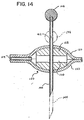
- the movable section 148 of the upper housing portion 132 Prior to use of the device 116, the movable section 148 of the upper housing portion 132 is in the portion shown in solid lines in Fig. 14. In this position, the cannula 144 of the injection needle 142 is recessed entirely within the housing, and a hole 162 formed in the side of the cannula 144 is located at a position above and outside the delivery node 150. As shown in Fig. 13, the plastic cap 146 at the top of the injection needle 142 is held in a socket 164 which is affixed to the bottom surface of the movable housing section 148. To inject the needle 142, the user depresses the movable housing section 148 until it reaches the solid line position shown in Fig. 13.
- An elastomeric seal 168 is provided in the delivery node 150 in order to prevent leakage of the liquid therapeutic preparation at the membranes 120, 122 and the cannula 144 of the injection needle 142.
- the elastomeric seal 168 also defines a central opening 170 with which the side opening 162 in the needle cannula 144 can align, thereby insuring that the desired fluid path will exist.
- the opening 162 can be formed in the cannula 144 in various ways, but a technique known as electrical discharge machining (EDM) is particularly useful for this purpose.
- EDM electrical discharge machining
- the automatic injection device 116 can be removed from the body of the patient in the same manner as the device 20 described previously.
- the movable section 148 in the upper portion 132 of the housing can be raised to the position shown in phantom lines in Fig. 13.
- the cannula 144 is withdrawn from the delivery node 150, and a spring 172 in the socket 164 causes the injection needle 142 to pivot to a position generally parallel to the inside surface of the movable housing section 148.
- the movable housing section 148 may then be restored to its closed position, leaving the injection needle 142 fully retracted at a safe position within the housing.
- the automatic injection devices 20 and 116 can be used to administer virtually any type of therapeutic preparation that is in a liquid or flowable form. Examples include liquids, solutions, suspensions, flowable gels and the like. It will also be apparent that the devices 20 and 116 can be used for either intradermal, subcutaneous, intramuscular or intravenous delivery of the therapeutic preparation.
Abstract
Description
- The present invention relates generally to a device for delivering a liquid therapeutic preparation into the body of a patient by injection into or though the patient's skin. More particularly, the invention relates to a low-profile automatic injection device that can be worn inconspicuously under the clothing of a patient to allow a liquid therapeutic preparation (such as insulin) to be administered over an extended period of time, and that incorporates a self-emptying reservoir to eliminate the need for a pump or other type of discharge device.
- Various types of automatic injection devices have been developed to allow drug solutions and other liquid therapeutic preparations to be administered by untrained personnel. Generally, these devices include a reservoir that is pre-filled with the liquid therapeutic preparation, and some type of automatic needle-driving mechanism (usually of the spring-loaded type) that can be triggered by the user. Examples of such devices may be found in U.S. Patent Nos. 4,188,950,4,196,732,4,258,713,4,227,528 and 4,378,015, all to Stephen C. Wardlaw. Still further examples can be found in U.S. Patent No. 4,214,584 to Smirnov et al., U.S. Patent Nos. 4,894,054 and 5,527,287, both to Miskinyar, and U.S. Patent No. 5,616,132, to Newman.
- In order to start the flow of the liquid therapeutic preparation when the needle is injected, the devices disclosed in the aforementioned patents generally employ movable ampoules, pistons or other complex arrangements which are somewhat difficult to manufacture. Moreover, the design of these devices generally requires that the reservoir be positioned above the needle driving mechanism, which results in a device of considerable height. This is not necessarily a problem when the drug solution is to be injected as a bolus at one discrete time, as most of these devices are designed to do, but it is a distinct disadvantage when the drug solution is to be infused into the patient over an extended period of time. In these latter instances, the injection device may have to be held in contact with the patient's skin (e.g., by tape or an adhesive) for several hours or more, and this is difficult to achieve when the device has a large height dimension.
- Another class of devices includes those which are capable of gradually infusing a liquid therapeutic preparation into the skin of a patient. In some cases, these devices are small enough (both in height and in overall size) to allow them to be "worn" by an ambulatory patient while the liquid therapeutic preparation is being infused into the patient. Examples of devices which fall in to this class include those disclosed in U.S. Patent Nos. 4,340,048 and 4,753,651, both to Eckenhoff, U.S. Patent No. 4,734,092, to Millerd, U.S. Patent No. 4,781,688, to Thoma et al., U.S. Patent No. 4,886,499, to Cirelli et al., U.S. Patent No. 5,656,032, to Kriesel et al., and PCT Publication Nos. WO 95/13838 and WO 97/21457, both to Elan Medical Technologies, Ltd.
- Unfortunately, most of the automatic infusion devices disclosed in the prior art are fairly complex in design and, as a result, cannot be made as small and inexpensive as might be desired. Generally, the complexity of these devices results from three factors. One factor is the need for a pump or other type of discharge mechanism to force the liquid therapeutic preparation to flow out of the reservoir and into the injection or infusion needle. Another factor is the need for some type of valve or flow control mechanism to cause the liquid therapeutic preparation to begin to flow at the proper time. A third factor, which applies to those devices that are designed to inject the infusion needle into the patient automatically, is the need for a suitable injection mechanism that can be triggered by the user. The structures required to perform these functions add size and complexity to the infusion device, making it larger than desired and relatively expensive to manufacture.
- Accordingly, a need exists for an automatic injection device that is small and has a low-profile configuration, allowing it to be conveniently handled and worn (preferably in an inconspicuous manner under the clothing) by an ambulatory patient. A need also exists for an automatic injection device which is capable of infusing a drug solution or other liquid therapeutic preparation into the skin of a patient over an extended period of time. Finally, a need exists for an automatic injection device whose basic design allows it to be not only small and low in height, but also simple and inexpensive to manufacture.
- In accordance with the present invention, a device for delivering a liquid therapeutic preparation into the body of a patient by injection into or through the skin of the patient comprises a housing adapted to be held in contact with the patient's skin. A reservoir is disposed within the housing for containing a liquid therapeutic preparation to be administered. The reservoir includes a Belleville spring which exerts pressure on the liquid therapeutic preparation to discharge the liquid therapeutic preparation from the reservoir at a relatively constant rate. An injection needle is adapted to communicate with the reservoir and to project from the housing in order to inject the liquid therapeutic preparation into or through the skin of the patient.
- The various objects, advantages and novel features of the present invention will be more readily appreciated from the following detailed description when read in conjunction with the appended drawings, in which:
- Fig. 1 is a top perspective view of an automatic injection device constructed in accordance with a first embodiment of the present invention;
- Fig. 2 is a bottom perspective view of the automatic injection device of Fig. 1, illustrating the needle aperture and peelable release liner thereof;
- Fig. 3 is a partially exploded perspective view of the automatic injection device of Figs. 1 and 2, with the top portion of the housing removed and the internal components of the device shown in their operative positions in the bottom portion of the housing;
- Fig. 4 is a fully exploded perspective view of the automatic injection device of Figs. 1-3, with the internal components of the device shown removed from the bottom portion of the housing;
- Fig. 5 is a cross-sectional view taken along the line 5-5 in Fig. 1, illustrating the components of the automatic injection device in the positions they occupy prior to use of the device;
- Fig. 6 is a cross-sectional view similar to that of Fig. 5, illustrating the components of the automatic injection device in the positions they occupy during and after use;
- Fig. 7 is an enlarged side view of the injection needle used in the device of Figs. 1-6, showing the capillary tube that is used for flow rate control;
- Fig. 8 is a side view of an alternative embodiment of the injection needle in which a valve is used for flow rate control;
- Fig. 9 is a cross-sectional view of the liquid reservoir or dose chamber used in the device of Figs. 1-8, with the liquid therapeutic preparation present within the reservoir;
- Figs. 10 and 11 illustrate the components of the liquid reservoir of Fig. 8 and the manner in which they are assembled;
- Fig. 12 is an exploded perspective view of an automatic injection device constructed in accordance with a second embodiment of the present invention;
- Fig. 13 is a cross-sectional view of the automatic injection device of Fig. 12, shown fully assembled; and
- Fig. 14 is an enlarged view of a portion of Fig. 13, illustrating the manner in which the flow of the drug solution to the injection needle is controlled.
-
- Throughout the drawings, like reference numerals will be understood to refer to like parts and components.
- An
automatic injection device 20 constructed in accordance with a first embodiment of the present invention is illustrated generally in the top and bottom perspective views of Figs. 1 and 2, respectively. Thedevice 20 includes a rigidexternal housing 21 that consists of anupper housing portion 22 and alower housing portion 24. Thehousing portions horizontal seam 26. The plastic material used for thehousing 21 is preferably opaque, but may be transparent or translucent if desired. When viewed from above or below, thehousing 21 has an oblong shape with rounded ends, as shown. Theforward end 28 of thehousing 21 is closed, but therear end 30 of the housing includes a horizontally-extending slot 32 (formed by a notch in the upper housing portion 22) which allows access to the interior of the housing. Theslot 32 allows a pre-filled liquid reservoir or dose chamber to be installed in thehousing 21 after thedevice 20 has been assembled. Horizontal, crescent-shaped cut-outs lower portions housing 21 at therear end 30 thereof to allow the liquid reservoir to be fully inserted. - As shown in Fig. 1, the
upper portion 22 of the housing is formed with arecessed area 38 in which ahole 40 is formed. Thehole 40 is elongated in the lengthwise direction of thedevice 20, and accommodates aslide button 42 which is operated by the user. The top surface of theslide button 42 is ribbed in a direction perpendicular to the direction of button movement, as shown, to allow the user's finger to engage thebutton 42 without slipping. Thebutton 42 is initially in the position shown in Fig. 1 and is moved rearwardly (i.e., in the direction toward therear end 30 of the housing 21) by the user during operation of thedevice 20. As will be described in detail below, movement of thebutton 42 causes an injection needle to project from the bottom of thehousing 21 and also causes the liquid therapeutic preparation to begin to flow through the injection needle from the internal reservoir. - As shown in Fig. 2, the bottom surface of the housing is flat and carries a layer of pressure-
sensitive adhesive 44 which allows thedevice 20 to be affixed to the skin of a patient. The tackiness of theadhesive layer 44 is sufficient to allow thedevice 20 to remain securely attached to the patient's body, but is weak enough to allow thedevice 20 to be removed from the skin after use without discomfort. A suitable adhesive which may be used for this purpose is available from 3M Company of St. Paul, Minnesota. Preferably, the bottom surface of thehousing 21 is roughened or textured to allow for better adhesion of the pressure-sensitiveadhesive layer 44 to the plastic material of the housing. Arelease liner 46, made of coated paper or a thin sheet of plastic, covers theadhesive layer 44 prior to use of thedevice 20. When therelease liner 46 is removed, it uncovers not only theadhesive layer 44 but also asmall round hole 48 that is formed through thebottom portion 24 of the housing near itsforward end 28. Thehole 48 serves as a needle aperture for allowing an injection needle to protrude from the bottom of thedevice 20 when theslide button 42 of Fig. 1 is actuated, as will be described in detail below. - In the preferred embodiment, the
automatic injection device 20 of Figs. 1 and 2 is approximately 9,1 cm (3.6 inches) in length, approximately 4,6 cm (1.8 inches) in width and approximately 1,0 cm (0.4 inch) or less in height. However, these dimensions are given merely by way of example and not by way of limitation, it being understood that both the dimensions of thedevice 20 and its overall shape or geometry may be varied in order to suit the requirements of particular applications. - Figs. 3 and 4 are exploded views which illustrate the internal components of the
automatic injection device 20. These components include a liquid reservoir ordose chamber 50, aneedle carrier 52 and aninjection needle 54. Theliquid reservoir 50, whose detailed construction will be discussed below in connection with Figs. 9-11, is preferably in the form of a thin disk-shaped structure as shown. A cylindrical fill and dischargeport 56 is formed on the side of thereservoir 50 and faces therear edge 69 of theneedle carrier 52. Theliquid reservoir 50 is made of a suitable plastic material, such as ABS plastic, and defines a thin, disk-shaped internal chamber in which a liquid therapeutic preparation (such as insulin) is stored. Thecircular aperture 57 of theport 56 is closed off by an internal, self-sealing rubber septum (not visible in Figs. 3 and 4) which maintains thereservoir 50 in a sealed condition until it is penetrated by theinjection needle 54 during use of thedevice 20. Preferably, thereservoir 50 is pre-filled with the liquid therapeutic preparation (via needle injection through the port 56) and is inserted into theautomatic injection device 20 through theslot 32 after thedevice 20 has been assembled. When thereservoir 50 is inserted into theslot 32, a pair ofupstanding ramps 58 which are integrally formed on thebottom portion 28 of the housing assist in locating thereservoir 50 at the proper height within the housing. A similar pair of ramps 60, spaced more closely together and located closer to theforward end 28 of the housing than theramps 58, engage a pair of horizontal wings ortabs 62 which extend from either side of theport 56. As a result, thecircular aperture 57 at the center of theport 56 is aligned precisely with the rearwardly-facingend 63 of theinjection needle 54. When thereservoir 50 reaches the proper position within thehousing 21, the rear edges of thewings 62 are captured between a pair ofupstanding detents 64 which, like theramps 58 and 60, are formed integrally with thebottom portion 24 of thehousing 21. Thedetents 64 serve to lock thereservoir 50 in position within thehousing 21 of theautomatic injection device 20. Thereservoir 50 is guided into engagement with thedetents 64 by ashallow channel 65 which receives the lowermost edge of theport 56 and extends longitudinally along the interior surface of thebottom housing portion 24. Asimilar channel 66 extends longitudinally along the interior surface of theupper housing portion 22 to receive and guide the uppermost edge of theport 56. - With continued reference to Figs. 3 and 4, the
needle carrier 52 is received in thelower portion 24 of the housing in a side-by-side relationship with thereservoir 50. Theneedle carrier 52 is made of a strip of resilient plastic material, such as 1,0 mm (0.040 inch) thick ABS plastic. Theneedle carrier 52 includes a generallyrectangular guide portion 68 on which theslide button 42 is integrally formed. Therear edge 69 of theguide portion 68 faces thereservoir 50, and is separated from theport 56 of the reservoir by a small gap 70 as shown in Fig. 3. Integral with theguide portion 68 of theneedle carrier 52 is a resiliently deflectable portion 71 which, when viewed from above, has an arcuate or curved shape corresponding generally to the shape of theforward portion 28 of the housing. As best seen in Fig. 4, the resiliently deflectable portion 71 of theneedle carrier 52 is angled downwardly (preferably by about 7°) from the plane of theguide portion 68 when the deflectable portion 71 is in its relaxed or unstressed condition. Theinjection needle 54 is secured to the bottom surface of theneedle carrier 52 in a manner such that the main or unbentportion 72 of theinjection needle 54 extends approximately parallel to the plane of thelower housing portion 24 and is aligned with the longitudinal center line of thedevice 20. Theinjection needle 54 may be affixed to the lower surface of theneedle carrier 52 in any desired manner, but the preferred method is to capture portions of theinjection needle 54 between projections (two of which are visible at 74 in Fig. 4) extending from the lower surface of theneedle carrier 52. An epoxy resin may also be used to secure theinjection needle 54 in place. The forward ordistal end 76 of theinjection needle 54 is bent at an angle of about 90° relative to the main orproximal portion 72 of the injection needle, and penetrates the skin of the patient during operation of thedevice 20. As described below in connection with Figs. 7 and 8, theinjection needle 54 is preferably made up of two connected sections of hollow 30-gauge stainless steel cannula, with each section ground at an angle at its free end to provide a sharpeneddistal end 78 and a sharpenedproximal end 63. The 90 ° bend which separates thedistal portion 76 of theinjection needle 54 from the main orproximal portion 72 is preferably in the form of a smooth arc, as shown, in order to avoid any obstruction in the flow of the liquid therapeutic preparation through theinjection needle 54. - Unlike the
liquid reservoir 50, which is held at a fixed position within thehousing 21, theneedle carrier 52 is slidable relative to thelower portion 24 of the housing. This is achieved by means of a pair of upstandingguide track structures 82 which are formed integrally with thelower portion 24 of the housing. As best seen in Fig. 3, therectangular guide portion 68 of theneedle carrier 52 is slidably received between the guide tracks 82 so that it can move longitudinally (i.e., in the direction toward the liquid reservoir 50) when theslide button 42 is manipulated by the user. This provides a corresponding motion of theinjection needle 54, which is affixed to the bottom of theneedle carrier 52 as described previously. During movement of theneedle carrier 52, the upper and lower horizontal portions of the guide tracks 82 restrain vertical movement of theguide portion 68. When theneedle carrier 52 is at its forwardmost position in thelower housing portion 24, the front edge 85 of the resiliently deflectable portion 71 is deflected upwardly from its relaxed or unstressed configuration by a pair of upstanding rectangular supports orprojections 84 which are formed integrally with thebottom portion 24 of the housing near itsforward end 28. Since theguide portion 68 at the rear of theneedle carrier 52 is prevented from moving upwardly by the guide tracks 82, theneedle carrier 52 is thus maintained in a resiliently stressed condition with the forward edge of the resiliently deflectable portion 71 bearing downwardly on thesupports 84. This is the condition in which theneedle carrier 52 exists prior to use of theautomatic injection device 20. When thedevice 20 is used, theneedle carrier 52 is moved (via the slide button 42) in the direction toward thereservoir 50, thereby removing the forward edge 85 of the resiliently deflectable portion 70 from contact with thesupports 84. This allows the resiliently deflectable portion 70 of theneedle carrier 52 to deflect downwardly under its own inherent spring force. This motion provides the injection force that causes thedistal portion 76 of theinjection needle 54 to penetrate the skin of the patient. - As shown in Figs. 3 and 4, upstanding
cylindrical sockets 86 are integrally formed on the interior surface of thelower housing portion 24. Thesesockets 86 mate with corresponding pins orstuds 88 which are formed integrally with the interior surface of theupper housing portion 22 and which extend downwardly toward the lower housing portion. Tight engagement between thepins 88 andsockets 86 serves to couple the upper andlower housing portions automatic injection device 20. - Figs. 5 and 6 are cross-sectional views which illustrate the manner in which the
automatic injection device 20 is used. Fig. 5 illustrates thedevice 20 as it would appear prior to use, with theslide button 42 in its forwardmost position and thedistal tip 78 of theinjection needle 54 recessed within theforward end 28 of thehousing 21. Therelease liner 46 has been removed from the bottom of thehousing 21 in Fig. 5, and the bottom surface of the housing has been placed against the skin of the patient (not shown) so that theneedle aperture 48 is directly over the desired injection site. When theslide button 42 is moved rearwardly in the hole 40 (i.e., in the direction toward the reservoir 50), the forward edge 85 of the deflectable portion 71 of theneedle carrier 52 is withdrawn from thesupports 84, allowing the deflectable portion 71 to resiliently return to its relaxed or unstressed condition as shown in Fig. 6. When this occurs, thebent portion 76 of theinjection needle 54 projects downwardly through theneedle aperture 48 and the sharpeneddistal tip 78 of the injection needle penetrates the skin of the patient. The depth of penetration is preferably about 3 millimeters or less. At the same time, the rearward movement of theneedle carrier 52 causes the sharpenedtip 63 at the proximal end of theinjection needle 54 to penetrate a self-sealingrubber septum 90 in theport 56 of theliquid reservoir 50. The proximal end of theinjection needle 54 thereby enters the liquid chamber within thereservoir 50, as shown in Fig. 6, and a flow path is established between thereservoir 50 and the body of the patient through the lumen of theinjection needle 54. It will be appreciated that contact between theport 56 and therear edge 69 of theneedle carrier 52 will act as a stop for the rearward motion of theinjection needle 54, thereby limiting the depth of penetration of theinjection needle 54 into thereservoir 50. As will be discussed in connection with Figs. 7 and 8, the rate of liquid flow through theinjection needle 54 is controlled so that the liquid therapeutic preparation is discharged from thereservoir 50 gradually over a predetermined interval. In the case where the liquid therapeutic preparation is insulin, for example, this period of time may be approximately twenty-four hours. As will become apparent from the discussion of Figs. 9-11 below, the inherent resiliency of the walls of theliquid reservoir 50 allows the liquid therapeutic preparation to be discharged from thereservoir 50 without the need for a pump or other type of discharge device. - Fig. 7 illustrates a preferred type of
injection needle 54 which may be employed in the present invention. Theinjection needle 54 is made up of twosections cannula sections glass capillary tube 96 provides a fixed, calibrated flow resistance that establishes the rate of liquid flow through theinjection needle 54. In the preferred embodiment, theglass capillary tube 96 has a length of approximately 24,5 mm (1 inch), an outer diameter of approximately 150 microns and an inner diameter of approximately 29 microns. The epoxy resin that is used to attach theinjection needle 54 to theneedle carrier 52 may also be used to secure the connection between theglass capillary tube 96 and the stainlesssteel cannula sections - Fig. 8 illustrates a modified embodiment in which the
cannula sections valve 98 rather than by theglass capillary tube 96. When thevalve 98 is closed, the liquid therapeutic preparation is prevented from flowing through theinjection needle 54. When thevalve 98 is opened, the liquid therapeutic preparation can flow through theinjection needle 54 and into the body of the patient. The size of the valve orifice controls the rate of liquid flow through theinjection needle 54. Thevalve 98 may be controlled either mechanically or electrically. In either case, the valve control can be interconnected with theslide button 42 or provided as a separate control on the exterior of thehousing 21. Optionally, a proportional valve may be used so that the rate of liquid flow through theinjection needle 54 can be varied to suit the requirements of particular patients and/or liquid therapeutic preparations. - Figs. 9-11 illustrate the details of the
liquid reservoir 50. In Fig. 9, thereservoir 50 is shown in its assembled condition and is filled with a liquidtherapeutic preparation 100. The body of thereservoir 50 consists of two circularBelleville spring diaphragms Belleville spring diaphragm annular portion 106 which has a thickness of about 0,7 mm (0.030 inch), and a thinnercentral disk portion 108 which has a thickness of about 0,5 mm (0.020 inch).Semicylindrical structures Belleville spring diaphragm port 56. A self-sealingcylindrical rubber septum 90 is captured within a correspondingly-shapedcavity in theport 56 to seal theaperture 57, which serves as the inlet and outlet of thereservoir 50. In the empty condition of thereservoir 50, the inner surfaces of theBelleville spring diaphragms therapeutic preparation 100 is injected under pressure by a filling needle through therubber septum 90, and this causes theBelleville spring diaphragms rubber septum 90 self-seals and maintains the liquidtherapeutic preparation 100 in a pressurized condition within thereservoir 50. - Fig. 10 illustrates the configuration of the
Belleville spring diaphragms reservoir 50 is assembled. As illustrated, eachBelleville spring diaphragm Belleville spring diaphragms Belleville spring diaphragms port 56. The gap provides a liquid channel which communicates with theseptum 90 andaperture 57. After the ultrasonic bonding operation is complete, thereservoir 50 has the configuration shown in Fig. 11. As noted earlier, introduction of the liquidtherapeutic preparation 100 under pressure through theseptum 90 causes theBelleville spring diaphragms Belleville spring diaphragms 102 and 104 (which tends to return them to the configuration shown in Fig. 10) maintains the liquidtherapeutic preparation 100 under pressure. When theinjection needle 54 of theautomatic injection device 20 penetrates theseptum 90, the pressure exerted by theBelleville spring diaphragms therapeutic preparation 100 to be discharged through theinjection needle 54 without the need for a pump or other type of discharge device. - One of the advantages of the reservoir construction shown in Figs. 9-11 is that the
Belleville spring diaphragms therapeutic preparation 100 that is essentially independent of the amount of liquid remaining within thereservoir 50. This produces a relatively constant flow rate of the liquidtherapeutic preparation 100 through theinjection needle 54, which allows the liquidtherapeutic preparation 100 to be administered to the patient at a constant infusion rate. In order to achieve this result, a specific geometry is preferably used for each of theBelleville spring diaphragms annular region 106 of each Belleville spring diaphragm (the dimension "h" in Fig. 10) and the thickness of this region (the dimension "t" in Fig. 10) should be in the range of about 1.7 to about 2.0. For a Belleville spring diaphragm having an effective diameter (the dimension "d" in Fig. 10) of about 42 mm (1.70 inches), the dimension "h" preferably has a value of about 1,4 mm(0.060 inch) and the dimension "t" preferably has a value of about 0,7 mm (0.030 inch). When thereservoir 50 is completely filled with the liquid therapeutic preparation as shown in Fig. 9, the interior height dimension at the center of the reservoir is about 1,4 mm (0.060 inch). - Fig. 12 is an exploded perspective view of an
automatic injection device 116 constructed in accordance with a second embodiment of the present invention. In this embodiment, theliquid reservoir 118 comprises twoflexible membranes Belleville washer 124 with ahollow center 126 is bonded to the outside of thetop membrane 120, and a similar Belleville washer 128 (visible in Fig. 13) with ahollow center 130 is bonded to the outside of thebottom membrane 122. Except for theirhollow centers Belleville washers Belleville spring diaphragms Belleville washers liquid reservoir 118, but theBelleville washers membranes Belleville washers reservoir 118. - With further reference to Fig. 12, the
liquid reservoir 118 is enclosed in a housing which consists of anupper portion 132 and alower portion 134.Pins 136 extend downwardly from theupper portion 132 of the housing and mate withsockets 138 formed in thelower portion 134 of the housing after passing throughholes 140 located at the periphery of the bondedmembranes lower housing portions liquid reservoir 118 within the housing. Also visible in Fig. 12 is aninjection needle 142 which communicates with theliquid reservoir 118. Theinjection needle 142 consists of a straightstainless steel cannula 144 which is ground at an angle at its lower end, and is capped at its upper end by around plastic insert 146. Actuation of a hinged cut-outsection 148 of theupper housing portion 132 by the user causes the injection needle to be displaced through adelivery node 150 formed in anextension 152 of theliquid reservoir 118. Thedelivery node 150 is in fluid communication with the liquid therapeutic preparation in thereservoir 118 by means of aglass capillary tube 154 which serves as a fixed flow resistor and establishes the desired flow rate of the liquid therapeutic preparation through theinjection needle 142. - The manner in which the
automatic injection device 116 of Fig. 13 is used will now be explained with reference to Figs. 13 and 14. After thedevice 116 is assembled, theliquid reservoir 118 is filled by inserting a suitable filling nozzle through ahole 158 formed in theupper portion 132 of the housing and coupling the filling nozzle to aport 156 located on the rear portion of thereservoir 118. A ball-type check valve 160 allows the liquid therapeutic preparation to enter thereservoir 118 but prevents it from being discharged through theport 156 after the reservoir has been filled. Filling of thereservoir 118 will cause themembranes Belleville washers device 116, themovable section 148 of theupper housing portion 132 is in the portion shown in solid lines in Fig. 14. In this position, thecannula 144 of theinjection needle 142 is recessed entirely within the housing, and ahole 162 formed in the side of thecannula 144 is located at a position above and outside thedelivery node 150. As shown in Fig. 13, theplastic cap 146 at the top of theinjection needle 142 is held in asocket 164 which is affixed to the bottom surface of themovable housing section 148. To inject theneedle 142, the user depresses themovable housing section 148 until it reaches the solid line position shown in Fig. 13. This causes the distal end of theinjection needle 142 to project from aneedle aperture 166 in thebottom portion 134 of the housing, and also causes the portion of the injection needle cannula containing thehole 162 to enter the delivery node 150 (as illustrated in phantom lines in Fig. 14). When thehole 162 aligns with the center of thedelivery node 150, a liquid path exists between the interior of thereservoir 118 and the distal tip of theinjection needle 142. The liquid therapeutic preparation is then automatically discharged from thereservoir 118 through theinjection needle 142 in the same manner as in the previous embodiment, with the rate of discharge being established by the dimensions of theglass capillary tube 154. Anelastomeric seal 168 is provided in thedelivery node 150 in order to prevent leakage of the liquid therapeutic preparation at themembranes cannula 144 of theinjection needle 142. Theelastomeric seal 168 also defines acentral opening 170 with which theside opening 162 in theneedle cannula 144 can align, thereby insuring that the desired fluid path will exist. Theopening 162 can be formed in thecannula 144 in various ways, but a technique known as electrical discharge machining (EDM) is particularly useful for this purpose. - After the liquid therapeutic preparation has been completely discharged from the
reservoir 118, theautomatic injection device 116 can be removed from the body of the patient in the same manner as thedevice 20 described previously. At this point, themovable section 148 in theupper portion 132 of the housing can be raised to the position shown in phantom lines in Fig. 13. When this is done, thecannula 144 is withdrawn from thedelivery node 150, and aspring 172 in thesocket 164 causes theinjection needle 142 to pivot to a position generally parallel to the inside surface of themovable housing section 148. Themovable housing section 148 may then be restored to its closed position, leaving theinjection needle 142 fully retracted at a safe position within the housing. - It will be appreciated that the
automatic injection devices devices - Although only two exemplary embodiments of the invention have been described in detail above, those skilled in the art will readily appreciate that many modifications are possible in the exemplary embodiments without materially departing from the novel teachings and advantages of this invention. Accordingly, all such modifications are intended to be included within the scope of the invention as defined in the following claims.
Claims (5)
- A device for delivering a liquid therapeutic preparation into the body of a patient by injection into or through the skin of the patient comprising:a housing (21;132,134) adapted to be held in contact with the skin of a patient;a reservoir (50;118) disposed within said housing for containing a liquid therapeutic preparation, said reservoir including a Belleville spring (102,104;124,128) which exerts pressure on said liquid therapeutic preparation to discharge said liquid therapeutic preparation from said reservoir at a relatively constant rate; andan injection needle (54;144) adapted to communicate with said reservoir (50;118) and to project from said housing in order to inject said liquid therapeutic preparation into or through the skin of the patient.
- A device as claimed in claim 1, wherein said reservoir (118) includes a self-sealing fill port (156) for allowing said liquid therapeutic preparation to be introduced into said reservoir under pressure.
- A device as claimed in claim 2 or 3, further comprising a flow regulator (96,98;154) disposed in the flow path of said liquid therapeutic preparation to cause said liquid therapeutic preparation be discharged from said reservoir (50;118) at a controlled rate, said flow regulator being selected from the group consisting of a fixed flow resistor and a controllable valve.
- A device as claimed in one of claims 1 - 3, wherein the injection needle (144) is pivotably supported by a movable section (148) of said housing and said needle (140) extends through a delivery node (150) and is pivotable about an axis (146) to a position generally parallel to the inside surface of said movable section (148).
- A device as claimed in claim 4, wherein the needle (144) has a hole (162) formed in the side of the needle (144), said hole being in communication with a central opening (170) extending through said node (150).
Applications Claiming Priority (3)
| Application Number | Priority Date | Filing Date | Title |
|---|---|---|---|
| US09/027,291 US5957895A (en) | 1998-02-20 | 1998-02-20 | Low-profile automatic injection device with self-emptying reservoir |
| EP99102038A EP0937475B1 (en) | 1998-02-20 | 1999-02-01 | Low-profile automatic injection device with self-emptying reservoir |
| US27291 | 2001-12-21 |
Related Parent Applications (1)
| Application Number | Title | Priority Date | Filing Date |
|---|---|---|---|
| EP99102038A Division EP0937475B1 (en) | 1998-02-20 | 1999-02-01 | Low-profile automatic injection device with self-emptying reservoir |
Publications (3)
| Publication Number | Publication Date |
|---|---|
| EP1464351A2 true EP1464351A2 (en) | 2004-10-06 |
| EP1464351A3 EP1464351A3 (en) | 2005-01-12 |
| EP1464351B1 EP1464351B1 (en) | 2007-01-03 |
Family
ID=21836831
Family Applications (2)
| Application Number | Title | Priority Date | Filing Date |
|---|---|---|---|
| EP99102038A Expired - Lifetime EP0937475B1 (en) | 1998-02-20 | 1999-02-01 | Low-profile automatic injection device with self-emptying reservoir |
| EP04011624A Expired - Lifetime EP1464351B1 (en) | 1998-02-20 | 1999-02-01 | Low-profile automatic injection device with self-emptying reservoir |
Family Applications Before (1)
| Application Number | Title | Priority Date | Filing Date |
|---|---|---|---|
| EP99102038A Expired - Lifetime EP0937475B1 (en) | 1998-02-20 | 1999-02-01 | Low-profile automatic injection device with self-emptying reservoir |
Country Status (5)
| Country | Link |
|---|---|
| US (2) | US5957895A (en) |
| EP (2) | EP0937475B1 (en) |
| JP (2) | JP3741889B2 (en) |
| CA (1) | CA2261408C (en) |
| DE (2) | DE69925055T2 (en) |
Cited By (21)
| Publication number | Priority date | Publication date | Assignee | Title |
|---|---|---|---|---|
| WO2008012817A1 (en) * | 2006-07-24 | 2008-01-31 | Medingo Ltd. | Systems, devices and methods for fluid/drug delivery |
| US8414522B2 (en) | 2006-02-09 | 2013-04-09 | Deka Products Limited Partnership | Fluid delivery systems and methods |
| US8414563B2 (en) | 2007-12-31 | 2013-04-09 | Deka Products Limited Partnership | Pump assembly with switch |
| US8496646B2 (en) | 2007-02-09 | 2013-07-30 | Deka Products Limited Partnership | Infusion pump assembly |
| US8679062B2 (en) | 2007-04-10 | 2014-03-25 | Roche Diagnostics Operations Inc. | Apparatus and method for pumping fluid |
| US9901514B2 (en) | 2007-04-30 | 2018-02-27 | Medtronic Minimed, Inc. | Automated filling systems and methods |
| US11141530B2 (en) | 2005-05-06 | 2021-10-12 | Medtronic Minimed, Inc. | Infusion device with base portion and durable portion |
| US11364335B2 (en) | 2006-02-09 | 2022-06-21 | Deka Products Limited Partnership | Apparatus, system and method for fluid delivery |
| US11395877B2 (en) | 2006-02-09 | 2022-07-26 | Deka Products Limited Partnership | Systems and methods for fluid delivery |
| US11404776B2 (en) | 2007-12-31 | 2022-08-02 | Deka Products Limited Partnership | Split ring resonator antenna adapted for use in wirelessly controlled medical device |
| US11426512B2 (en) | 2006-02-09 | 2022-08-30 | Deka Products Limited Partnership | Apparatus, systems and methods for an infusion pump assembly |
| US11478623B2 (en) | 2006-02-09 | 2022-10-25 | Deka Products Limited Partnership | Infusion pump assembly |
| US11497846B2 (en) | 2006-02-09 | 2022-11-15 | Deka Products Limited Partnership | Patch-sized fluid delivery systems and methods |
| US11497686B2 (en) | 2007-12-31 | 2022-11-15 | Deka Products Limited Partnership | Apparatus, system and method for fluid delivery |
| US11523972B2 (en) | 2018-04-24 | 2022-12-13 | Deka Products Limited Partnership | Apparatus, system and method for fluid delivery |
| US11524151B2 (en) | 2012-03-07 | 2022-12-13 | Deka Products Limited Partnership | Apparatus, system and method for fluid delivery |
| US11534542B2 (en) | 2007-12-31 | 2022-12-27 | Deka Products Limited Partnership | Apparatus, system and method for fluid delivery |
| US11597541B2 (en) | 2013-07-03 | 2023-03-07 | Deka Products Limited Partnership | Apparatus, system and method for fluid delivery |
| US11642283B2 (en) | 2007-12-31 | 2023-05-09 | Deka Products Limited Partnership | Method for fluid delivery |
| US11723841B2 (en) | 2007-12-31 | 2023-08-15 | Deka Products Limited Partnership | Apparatus, system and method for fluid delivery |
| US11890448B2 (en) | 2006-02-09 | 2024-02-06 | Deka Products Limited Partnership | Method and system for shape-memory alloy wire control |
Families Citing this family (381)
| Publication number | Priority date | Publication date | Assignee | Title |
|---|---|---|---|---|
| US20070142776A9 (en) * | 1997-02-05 | 2007-06-21 | Medtronic Minimed, Inc. | Insertion device for an insertion set and method of using the same |
| US7329239B2 (en) * | 1997-02-05 | 2008-02-12 | Medtronic Minimed, Inc. | Insertion device for an insertion set and method of using the same |
| US6607509B2 (en) * | 1997-12-31 | 2003-08-19 | Medtronic Minimed, Inc. | Insertion device for an insertion set and method of using the same |
| US5957895A (en) * | 1998-02-20 | 1999-09-28 | Becton Dickinson And Company | Low-profile automatic injection device with self-emptying reservoir |
| JP4425465B2 (en) | 1998-03-23 | 2010-03-03 | エラン コーポレーション ピーエルシー | Drug delivery device |
| US6368592B1 (en) | 1998-07-17 | 2002-04-09 | Massachusetts Institute Of Technology | Method of delivering oxygen to cells by electrolyzing water |
| US6406455B1 (en) * | 1998-12-18 | 2002-06-18 | Biovalve Technologies, Inc. | Injection devices |
| US20020095134A1 (en) * | 1999-10-14 | 2002-07-18 | Pettis Ronald J. | Method for altering drug pharmacokinetics based on medical delivery platform |
| US20020156453A1 (en) * | 1999-10-14 | 2002-10-24 | Pettis Ronald J. | Method and device for reducing therapeutic dosage |
| US8465468B1 (en) | 2000-06-29 | 2013-06-18 | Becton, Dickinson And Company | Intradermal delivery of substances |
| WO2001051109A1 (en) * | 2000-01-07 | 2001-07-19 | Biovalve Technologies, Inc. | Injection device |
| US20010041869A1 (en) * | 2000-03-23 | 2001-11-15 | Causey James D. | Control tabs for infusion devices and methods of using the same |
| US6485461B1 (en) * | 2000-04-04 | 2002-11-26 | Insulet, Inc. | Disposable infusion device |
| US6629949B1 (en) | 2000-05-08 | 2003-10-07 | Sterling Medivations, Inc. | Micro infusion drug delivery device |
| US6659982B2 (en) * | 2000-05-08 | 2003-12-09 | Sterling Medivations, Inc. | Micro infusion drug delivery device |
| US20050008683A1 (en) * | 2000-06-29 | 2005-01-13 | Becton Dickinson And Company | Method for delivering interferons to the intradermal compartment |
| US20040175360A1 (en) * | 2000-06-29 | 2004-09-09 | Pettis Ronald J. | Method for altering drug pharmacokinetics based on medical delivery platform |
| US6589229B1 (en) * | 2000-07-31 | 2003-07-08 | Becton, Dickinson And Company | Wearable, self-contained drug infusion device |
| CA2420048C (en) | 2000-08-18 | 2009-10-27 | Becton, Dickinson And Company | Constant rate fluid delivery device with selectable flow rate and titratable bolus button |
| AU8857501A (en) | 2000-09-08 | 2002-03-22 | Insulet Corp | Devices, systems and methods for patient infusion |
| US6669669B2 (en) | 2001-10-12 | 2003-12-30 | Insulet Corporation | Laminated patient infusion device |
| ES2314781T3 (en) * | 2000-11-09 | 2009-03-16 | Insulet Corporation | TRANSCUTANEOUS SUPPLY MEANS. |
| US6939324B2 (en) | 2000-11-30 | 2005-09-06 | Biovalve Technologies, Inc. | Fluid delivery and measurement systems and methods |
| US7931614B2 (en) | 2000-11-30 | 2011-04-26 | Valeritas, Inc. | Injection systems |
| US7052483B2 (en) * | 2000-12-19 | 2006-05-30 | Animas Corporation | Transcutaneous inserter for low-profile infusion sets |
| DE60115707T2 (en) * | 2000-12-21 | 2006-08-10 | Insulet Corp., Beverly | REMOTE CONTROL MEDICAL DEVICE |
| JP2004532670A (en) | 2001-02-22 | 2004-10-28 | インシュレット コーポレイション | Modular infusion device and method |
| JP2004525713A (en) * | 2001-04-13 | 2004-08-26 | ベクトン・ディキンソン・アンド・カンパニー | Methods and devices for administering substances into the intradermal layer of the skin for systemic absorption |
| ES2287275T3 (en) * | 2001-06-01 | 2007-12-16 | I-Flow Corporation | DEVICE FOR BIG VOLUME BALL. |
| US20030073609A1 (en) * | 2001-06-29 | 2003-04-17 | Pinkerton Thomas C. | Enhanced pharmacokinetic profile of intradermally delivered substances |
| BR0210628A (en) | 2001-06-29 | 2004-08-10 | Becton Dickinson Co | Intradermal release of vaccines and genetic therapeutic agents via microcannula |
| US20050010193A1 (en) * | 2002-05-06 | 2005-01-13 | Laurent Philippe E. | Novel methods for administration of drugs and devices useful thereof |
| US20030088238A1 (en) * | 2001-09-26 | 2003-05-08 | Poulsen Jens Ulrik | Modular drug delivery system |
| US20060122577A1 (en) * | 2001-09-26 | 2006-06-08 | Poulsen Jens U | Modular drug delivery system |
| US6689100B2 (en) | 2001-10-05 | 2004-02-10 | Becton, Dickinson And Company | Microdevice and method of delivering or withdrawing a substance through the skin of an animal |
| US7429258B2 (en) * | 2001-10-26 | 2008-09-30 | Massachusetts Institute Of Technology | Microneedle transport device |
| US20040120964A1 (en) * | 2001-10-29 | 2004-06-24 | Mikszta John A. | Needleless vaccination using chimeric yellow fever vaccine-vectored vaccines against heterologous flaviviruses |
| US20040078028A1 (en) * | 2001-11-09 | 2004-04-22 | Flaherty J. Christopher | Plunger assembly for patient infusion device |
| US20030109827A1 (en) * | 2001-12-07 | 2003-06-12 | Elan Pharma International Limited | Drug delivery system and method |
| ITTO20011228A1 (en) * | 2001-12-28 | 2003-06-28 | Cane Srl | DISPOSABLE NEEDLE CONTAINER. |
| US6692457B2 (en) | 2002-03-01 | 2004-02-17 | Insulet Corporation | Flow condition sensor assembly for patient infusion device |
| US6830558B2 (en) | 2002-03-01 | 2004-12-14 | Insulet Corporation | Flow condition sensor assembly for patient infusion device |
| EP1594559B1 (en) * | 2002-03-26 | 2013-02-13 | Becton, Dickinson and Company | Multi-stage fluid delivery device |
| US7115108B2 (en) * | 2002-04-02 | 2006-10-03 | Becton, Dickinson And Company | Method and device for intradermally delivering a substance |
| US6656159B2 (en) | 2002-04-23 | 2003-12-02 | Insulet Corporation | Dispenser for patient infusion device |
| US6656158B2 (en) | 2002-04-23 | 2003-12-02 | Insulet Corporation | Dispenser for patient infusion device |
| US6960192B1 (en) * | 2002-04-23 | 2005-11-01 | Insulet Corporation | Transcutaneous fluid delivery system |
| EP1501567B1 (en) * | 2002-05-06 | 2018-02-21 | Becton, Dickinson and Company | Device for controlling drug pharmacokinetics |
| US20060264886A9 (en) * | 2002-05-06 | 2006-11-23 | Pettis Ronald J | Method for altering insulin pharmacokinetics |
| US20050005710A1 (en) * | 2002-05-15 | 2005-01-13 | Therafuse, Inc. | Liquid metering system |
| US6932796B2 (en) * | 2002-05-15 | 2005-08-23 | Tearafuse, Inc. | Liquid metering system |
| US6979316B1 (en) | 2002-05-23 | 2005-12-27 | Seedlings Life Science Ventures Llc | Apparatus and method for rapid auto-injection of medication |
| US6723072B2 (en) | 2002-06-06 | 2004-04-20 | Insulet Corporation | Plunger assembly for patient infusion device |
| BRPI0312846B8 (en) * | 2002-07-22 | 2021-06-22 | Becton Dickinson Co | plaster-like infusion device |
| US20040059316A1 (en) * | 2002-07-31 | 2004-03-25 | Smedegaard Jorgen K. | Medical delivery device |
| EP1386626A1 (en) | 2002-07-31 | 2004-02-04 | Novo Nordisk A/S | Delivery device for treatment of diabetes mellitus |
| BR0313890A (en) * | 2002-08-30 | 2005-07-26 | Becton Dickinson Co | Pharmacokinetic control method of immunomodulatory compounds |
| US20040049129A1 (en) * | 2002-09-05 | 2004-03-11 | Yan Qi | Wafer assembly having a resilient extendable/retractable needle means for healthcare |
| US20040116905A1 (en) * | 2002-09-09 | 2004-06-17 | Pedersen Per Elgard | Flow restrictor with safety feature |
| AU2003278798A1 (en) * | 2002-09-12 | 2004-04-30 | Children's Hospital Medical Center | Method and device for painless injection of medication |
| US7435238B2 (en) * | 2002-09-13 | 2008-10-14 | Alan Reid | Needle device having retractable needle providing enhanced safety |
| US20050075670A1 (en) * | 2002-10-07 | 2005-04-07 | Henrik Bengtsson | Signal device with electro-muscle stimulation feature |
| US7014625B2 (en) * | 2002-10-07 | 2006-03-21 | Novo Nordick A/S | Needle insertion device |
| EP1556103A1 (en) * | 2002-10-07 | 2005-07-27 | Novo Nordisk A/S | Needle device comprising a plurality of needles |
| US20040102717A1 (en) * | 2002-11-26 | 2004-05-27 | Yan Qi | Disposable automatic safety assembly means for test and/or delivery |
| US7252651B2 (en) * | 2003-01-07 | 2007-08-07 | Becton, Dickinson And Company | Disposable injection device |
| WO2004089448A1 (en) | 2003-04-11 | 2004-10-21 | Novo Nordisk A/S | Delivery device |
| AU2004232289A1 (en) * | 2003-04-18 | 2004-11-04 | Insulet Corporation | User interface for infusion pump remote controller and method of using the same |
| ES2737835T3 (en) | 2003-04-23 | 2020-01-16 | Valeritas Inc | Hydraulically driven pump for long-term medication administration |
| US20040220551A1 (en) * | 2003-04-30 | 2004-11-04 | Flaherty J. Christopher | Low profile components for patient infusion device |
| JP2007525243A (en) * | 2003-04-30 | 2007-09-06 | インシュレット コーポレイション | RF medical device |
| DE602004025568D1 (en) | 2003-05-08 | 2010-04-01 | Novo Nordisk As | TILTABLE DEVICE FOR AN INJECTION NEEDLE |
| EP1475113A1 (en) * | 2003-05-08 | 2004-11-10 | Novo Nordisk A/S | External needle inserter |
| EP1624913B1 (en) | 2003-05-08 | 2010-07-21 | Novo Nordisk A/S | Skin mountable injection device with a detachable needle insertion actuation portion |
| WO2004098683A1 (en) * | 2003-05-08 | 2004-11-18 | Novo Nordisk A/S | Internal needle inserter |
| EP1635876A4 (en) * | 2003-06-13 | 2009-05-06 | Becton Dickinson Co | Improved intra-dermal delivery of biologically active agents |
| DE10327254B4 (en) * | 2003-06-17 | 2010-01-28 | Disetronic Licensing Ag | Modular infusion pump |
| EP1495775A1 (en) * | 2003-07-08 | 2005-01-12 | Novo Nordisk A/S | Portable drug delivery device having an encapsulated needle |
| WO2005002649A1 (en) * | 2003-07-08 | 2005-01-13 | Novo Nordisk A/S | Portable drug delivery device having an encapsulated needle |
| US7857131B2 (en) | 2003-08-12 | 2010-12-28 | Becton, Dickinson And Company | Patch-like infusion device |
| EP1502613A1 (en) | 2003-08-01 | 2005-02-02 | Novo Nordisk A/S | Needle device with retraction means |
| MXPA06002159A (en) * | 2003-08-26 | 2006-05-22 | Becton Dickinson Co | Methods for intradermal delivery of therapeutics agents. |
| US7361155B2 (en) * | 2003-09-16 | 2008-04-22 | Therafuse, Inc. | Compensating liquid delivery system and method |
| US7470266B2 (en) * | 2003-09-16 | 2008-12-30 | I-Flow Corporation | Fluid medication delivery device |
| IL157981A (en) | 2003-09-17 | 2014-01-30 | Elcam Medical Agricultural Cooperative Ass Ltd | Auto-injector |
| CN100586414C (en) * | 2003-10-21 | 2010-02-03 | 诺沃挪第克公司 | Reservoir device with inclined needle |
| EP1527792A1 (en) * | 2003-10-27 | 2005-05-04 | Novo Nordisk A/S | Medical injection device mountable to the skin |
| DE602004023756D1 (en) | 2003-10-21 | 2009-12-03 | Novo Nordisk As | INNER LIQUID CONNECTOR FOR THE PRODUCTION OF A LIQUID CONNECTION |
| ATE446111T1 (en) | 2003-10-21 | 2009-11-15 | Novo Nordisk As | INTERNAL FLUID CONNECTOR FOR PRODUCING A FLUID CONNECTION |
| KR20060099520A (en) * | 2003-10-21 | 2006-09-19 | 노보 노르디스크 에이/에스 | Medical skin mountable device |
| DE602004022075D1 (en) * | 2003-10-21 | 2009-08-27 | Novo Nordisk As | RESERVOIR DEVICE WITH INTEGRATED FASTENER |
| CN1871042B (en) * | 2003-10-21 | 2010-06-30 | 诺沃挪第克公司 | Internal fluid connector |
| WO2005037184A2 (en) * | 2003-10-21 | 2005-04-28 | Novo Nordisk A/S | Reservoir device with integrated mounting means |
| US7520867B2 (en) * | 2003-11-10 | 2009-04-21 | Medtronic Minimed, Inc. | Subcutaneous infusion set |
| US7494481B2 (en) * | 2004-12-03 | 2009-02-24 | Medtronic Minimed, Inc. | Multi-position infusion set device and process |
| US7731691B2 (en) | 2003-11-10 | 2010-06-08 | Smiths Medical Asd, Inc. | Subcutaneous infusion device and device for insertion of a cannula of an infusion device and method |
| AU2004298287B2 (en) * | 2003-12-16 | 2010-09-16 | Chimden Medical Pty. Ltd. | Fluid delivery device |
| WO2005058394A1 (en) * | 2003-12-16 | 2005-06-30 | Ultimate Medical Pty. Ltd. | Fluid delivery device |
| US20050177136A1 (en) * | 2003-12-19 | 2005-08-11 | Miller Landon C. | Externally disposed pump for use with an internally mounted and compliant catheter |
| WO2005072794A2 (en) * | 2004-01-29 | 2005-08-11 | M 2 Medical A/S | Disposable medicine dispensing device |
| WO2005072795A2 (en) * | 2004-01-29 | 2005-08-11 | M 2 Medical A/S | Disposable medicine dispensing device |
| US20050177030A1 (en) * | 2004-02-11 | 2005-08-11 | Scott Ponquinette | Physiological, DNA identification security monitoring, and response system |
| WO2005079440A2 (en) * | 2004-02-17 | 2005-09-01 | Children's Hospital Medical Center | Improved injection devicew for administering a vaccine |
| WO2005091922A2 (en) * | 2004-03-03 | 2005-10-06 | Becton, Dickinson And Company | Methods and devices for improving delivery of a substance to skin |
| IL160891A0 (en) | 2004-03-16 | 2004-08-31 | Auto-mix needle | |
| CA2560784A1 (en) | 2004-03-26 | 2005-10-06 | Unomedical A/S | Infusion set |
| EP1732626A1 (en) * | 2004-03-30 | 2006-12-20 | Novo Nordisk A/S | Actuator system comprising lever mechanism |
| EP1732625A1 (en) * | 2004-03-30 | 2006-12-20 | Novo Nordisk A/S | Actuator system comprising detection means |
| CA2559750C (en) | 2004-03-31 | 2014-01-07 | Eli Lilly And Company | Injection apparatus having a needle cassette for delivering a pharmaceutical liquid |
| US9380975B2 (en) * | 2004-05-07 | 2016-07-05 | Becton, Dickinson And Company | Contact activated lancet device |
| US20050256182A1 (en) * | 2004-05-11 | 2005-11-17 | Sutter Diane E | Formulations of anti-pain agents and methods of using the same |
| US20050267422A1 (en) * | 2004-05-26 | 2005-12-01 | Kriesel Marshall S | Fluid delivery apparatus |
| US20070156090A1 (en) * | 2004-05-26 | 2007-07-05 | Kriesel Marshall S | Fluid delivery apparatus |
| WO2005120433A1 (en) * | 2004-06-07 | 2005-12-22 | Novo Nordisk A/S | Reservoir with liquidly applied seal |
| AU2005253993B2 (en) * | 2004-06-09 | 2010-05-27 | Mark Anderson And Associates, Incorporated | Hypodermic injection system |
| EP1784890A4 (en) | 2004-06-14 | 2010-04-07 | Massachusetts Inst Technology | Electrochemical methods, devices, and structures |
| US7994686B2 (en) * | 2004-06-14 | 2011-08-09 | Massachusetts Institute Of Technology | Electrochemical methods, devices, and structures |
| US7872396B2 (en) | 2004-06-14 | 2011-01-18 | Massachusetts Institute Of Technology | Electrochemical actuator |
| US8247946B2 (en) | 2004-06-14 | 2012-08-21 | Massachusetts Institute Of Technology | Electrochemical actuator |
| US7999435B2 (en) * | 2004-06-14 | 2011-08-16 | Massachusetts Institute Of Technology | Electrochemical actuator |
| WO2006014425A1 (en) | 2004-07-02 | 2006-02-09 | Biovalve Technologies, Inc. | Methods and devices for delivering glp-1 and uses thereof |
| US8062250B2 (en) | 2004-08-10 | 2011-11-22 | Unomedical A/S | Cannula device |
| DE102004039408A1 (en) * | 2004-08-13 | 2006-03-02 | Disetronic Licensing Ag | Insertion head for medical or pharmaceutical applications |
| WO2006024650A2 (en) * | 2004-09-02 | 2006-03-09 | Novo Nordisk A/S | Medical device adapted for detection of drug condition |
| BRPI0515061B8 (en) * | 2004-09-10 | 2021-06-22 | Becton Dickinson Co | infusion device and method for reducing blistering when reconstituting a formula |
| WO2006032689A1 (en) | 2004-09-22 | 2006-03-30 | Novo Nordisk A/S | Medical device with transcutaneous cannula device |
| US20090012472A1 (en) * | 2004-09-22 | 2009-01-08 | Novo Nordisk A/S | Medical Device with Cannula Inserter |
| CN101060856B (en) | 2004-11-22 | 2011-01-19 | 诺和诺德公司 | Soluble, stable insulin-containing formulations with a protamine salt |
| US20090048563A1 (en) * | 2004-12-06 | 2009-02-19 | Novo Nordisk A/S | Ventilated Skin Mountable Device |
| US20060135910A1 (en) * | 2004-12-17 | 2006-06-22 | Luther Ronald B | Percutaneous safety needle inserter |
| WO2006075016A1 (en) * | 2005-01-17 | 2006-07-20 | Novo Nordisk A/S | Fluide delivery device with integrated monitoring of physiological characteristics |
| JP2008528086A (en) | 2005-01-24 | 2008-07-31 | ノボ・ノルデイスク・エー/エス | Medical device with protected puncture device |
| US20080188810A1 (en) * | 2005-02-25 | 2008-08-07 | Novo Nordisk A/S | Pump Assembly With Safety Valve |
| US7985199B2 (en) | 2005-03-17 | 2011-07-26 | Unomedical A/S | Gateway system |
| EP1877116A1 (en) | 2005-04-13 | 2008-01-16 | Novo Nordisk A/S | Medical skin mountable device and system |
| US8277415B2 (en) | 2006-08-23 | 2012-10-02 | Medtronic Minimed, Inc. | Infusion medium delivery device and method with drive device for driving plunger in reservoir |
| US20080097291A1 (en) | 2006-08-23 | 2008-04-24 | Hanson Ian B | Infusion pumps and methods and delivery devices and methods with same |
| US8512288B2 (en) | 2006-08-23 | 2013-08-20 | Medtronic Minimed, Inc. | Infusion medium delivery device and method with drive device for driving plunger in reservoir |
| US8137314B2 (en) | 2006-08-23 | 2012-03-20 | Medtronic Minimed, Inc. | Infusion medium delivery device and method with compressible or curved reservoir or conduit |
| US7905868B2 (en) | 2006-08-23 | 2011-03-15 | Medtronic Minimed, Inc. | Infusion medium delivery device and method with drive device for driving plunger in reservoir |
| US8840586B2 (en) | 2006-08-23 | 2014-09-23 | Medtronic Minimed, Inc. | Systems and methods allowing for reservoir filling and infusion medium delivery |
| US20080167641A1 (en) * | 2005-05-13 | 2008-07-10 | Novo Nordisk A/S | Medical Device Adapted To Detect Disengagement Of A Transcutaneous Device |
| ATE480278T1 (en) | 2005-09-12 | 2010-09-15 | Unomedical As | INTRODUCTION SYSTEM FOR AN INFUSION SET WITH A FIRST AND SECOND SPRING UNIT |
| EP1926511A1 (en) * | 2005-09-13 | 2008-06-04 | Novo Nordisk A/S | Reservoir device with inspection aid for detection of drug condition |
| WO2007045644A1 (en) | 2005-10-17 | 2007-04-26 | Novo Nordisk A/S | Vented drug reservoir unit |
| US7935104B2 (en) | 2005-11-07 | 2011-05-03 | Medingo, Ltd. | Systems and methods for sustained medical infusion and devices related thereto |
| EP1960018A1 (en) * | 2005-12-08 | 2008-08-27 | Novo Nordisk A/S | Medical system comprising a sensor device |
| RU2419460C2 (en) * | 2005-12-23 | 2011-05-27 | Уномедикал А/С | Injection device |
| US7704230B2 (en) * | 2005-12-29 | 2010-04-27 | Ethicon, Inc. | Pressurized fluid reservoir for an infusion system |
| EP1993637A2 (en) * | 2006-02-15 | 2008-11-26 | Medingo Ltd. | Systems and methods for sensing analyte and dispensing therapeutic fluid |
| AU2007219546B8 (en) | 2006-02-28 | 2012-07-05 | Unomedical A/S | Inserter for infusion part and infusion part provided with needle protector |
| CN101401313B (en) | 2006-03-13 | 2014-06-11 | 诺沃—诺迪斯克有限公司 | Secure pairing of electronic devices using dual means of communication |
| AU2007233231B2 (en) | 2006-03-30 | 2011-02-24 | Mannkind Corporation | Multi-cartridge fluid delivery device |
| WO2007122207A1 (en) | 2006-04-26 | 2007-11-01 | Novo Nordisk A/S | Skin-mountable device in packaging comprising coated seal member |
| CN101460207B (en) | 2006-06-06 | 2012-03-21 | 诺沃-诺迪斯克有限公司 | Assembly comprising skin-mountable device and packaging therefore |
| WO2007140783A2 (en) | 2006-06-07 | 2007-12-13 | Unomedical A/S | Inserter for transcutaneous sensor |
| MX2008015247A (en) | 2006-06-09 | 2008-12-15 | Unomedical As | Mounting pad. |
| ES2802600T3 (en) * | 2006-07-07 | 2021-01-20 | Hoffmann La Roche | Fluid Management Device and Operating Procedures |
| CN101522234B (en) * | 2006-07-24 | 2012-11-14 | 梅丁格有限公司 | Systems, devices and methods for fluid/drug delivery |
| KR20090037492A (en) | 2006-08-02 | 2009-04-15 | 우노메디컬 에이/에스 | Cannula and delivery device |
| US7811262B2 (en) | 2006-08-23 | 2010-10-12 | Medtronic Minimed, Inc. | Systems and methods allowing for reservoir filling and infusion medium delivery |
| US7794434B2 (en) | 2006-08-23 | 2010-09-14 | Medtronic Minimed, Inc. | Systems and methods allowing for reservoir filling and infusion medium delivery |
| US7828764B2 (en) | 2006-08-23 | 2010-11-09 | Medtronic Minimed, Inc. | Systems and methods allowing for reservoir filling and infusion medium delivery |
| US7789857B2 (en) | 2006-08-23 | 2010-09-07 | Medtronic Minimed, Inc. | Infusion medium delivery system, device and method with needle inserter and needle inserter device and method |
| US20080097317A1 (en) * | 2006-08-25 | 2008-04-24 | Jeffery Alholm | Infusion pump |
| US8202267B2 (en) | 2006-10-10 | 2012-06-19 | Medsolve Technologies, Inc. | Method and apparatus for infusing liquid to a body |
| EP1917990A1 (en) | 2006-10-31 | 2008-05-07 | Unomedical A/S | Infusion set |
| EP3998095B1 (en) | 2006-12-22 | 2024-01-31 | F. Hoffmann-La Roche AG | Device for sustained delivery of a therapeutic fluid |
| EP2601883A1 (en) | 2006-12-22 | 2013-06-12 | Medingo Ltd. | Fluid delivery with in vivo electrochemical analyte sensing |
| WO2008083209A2 (en) * | 2006-12-29 | 2008-07-10 | Amir Genosar | Hypodermic drug delivery reservoir and apparatus |
| JP2010520409A (en) * | 2007-03-06 | 2010-06-10 | ノボ・ノルデイスク・エー/エス | Pump assembly with actuator system |
| DE502007005457D1 (en) * | 2007-03-14 | 2010-12-09 | Roche Diagnostics Gmbh | Insertion head for medical or pharmaceutical applications |
| EP1970084B8 (en) * | 2007-03-14 | 2010-09-22 | F. Hoffmann-La Roche Ltd. | Insertion device for an insertion head, in particular for an infusion set |
| US7959715B2 (en) | 2007-04-30 | 2011-06-14 | Medtronic Minimed, Inc. | Systems and methods allowing for reservoir air bubble management |
| JP5102350B2 (en) | 2007-04-30 | 2012-12-19 | メドトロニック ミニメド インコーポレイテッド | Reservoir filling / bubble management / infusion medium delivery system and method using the system |
| US8323250B2 (en) | 2007-04-30 | 2012-12-04 | Medtronic Minimed, Inc. | Adhesive patch systems and methods |
| US8434528B2 (en) | 2007-04-30 | 2013-05-07 | Medtronic Minimed, Inc. | Systems and methods for reservoir filling |
| US8613725B2 (en) | 2007-04-30 | 2013-12-24 | Medtronic Minimed, Inc. | Reservoir systems and methods |
| US8597243B2 (en) | 2007-04-30 | 2013-12-03 | Medtronic Minimed, Inc. | Systems and methods allowing for reservoir air bubble management |
| EP2152148A2 (en) * | 2007-05-07 | 2010-02-17 | Medingo Ltd. | Reciprocating delivery of fluids to the body with analyte concentration monitoring |
| US8568365B2 (en) * | 2007-05-08 | 2013-10-29 | Alan Reid | Methods and apparatus for syringe adapter |
| CN101687075B (en) * | 2007-05-11 | 2013-04-10 | 梅丁格有限公司 | A positive displacement pump |
| EP2164458A1 (en) | 2007-06-01 | 2010-03-24 | Novo Nordisk A/S | Stable non-aqueous pharmaceutical compositions |
| CA2692038A1 (en) * | 2007-06-15 | 2008-12-24 | Lifescan, Inc. | Flexible cannula or medical device conduit |
| AU2008266382B2 (en) | 2007-06-20 | 2013-06-27 | Unomedical A/S | A catheter and a method and an apparatus for making such catheter |
| US20100174239A1 (en) | 2007-06-27 | 2010-07-08 | Ofer Yodfat | Tubing for Fluid Delivery Device |
| EP2185224A1 (en) | 2007-07-03 | 2010-05-19 | Unomedical A/S | Inserter having bistable equilibrium states |
| AU2008274311A1 (en) | 2007-07-10 | 2009-01-15 | Unomedical A/S | Inserter having two springs |
| JP2010533524A (en) | 2007-07-18 | 2010-10-28 | ウノメディカル アクティーゼルスカブ | Insertion device with pivoting action |
| DK2183006T3 (en) * | 2007-07-20 | 2019-04-01 | Hoffmann La Roche | Portable infusion device with manual control |
| WO2009013735A1 (en) | 2007-07-20 | 2009-01-29 | Medingo Ltd. | Vented dispensing device and method |
| US7828771B2 (en) * | 2007-07-26 | 2010-11-09 | Entra Pharmaceuticals, Inc. | Systems and methods for delivering drugs |
| CN101808680B (en) | 2007-08-01 | 2014-07-02 | F·霍夫曼-拉罗氏股份公司 | Portable infusion device provided with means for monitoring and controlling fluid delivery |
| WO2009016635A2 (en) | 2007-08-01 | 2009-02-05 | Medingo Ltd. | Detachable portable infusion device |
| AU2008302516B2 (en) | 2007-09-17 | 2013-09-19 | Tecpharma Licensing Ag | Insertion devices for infusion devices |
| US8128596B2 (en) * | 2007-09-28 | 2012-03-06 | Calibra Medial, Inc. | Disposable infusion device layered structure |
| US7967795B1 (en) | 2010-01-19 | 2011-06-28 | Lamodel Ltd. | Cartridge interface assembly with driving plunger |
| BRPI0817907B8 (en) | 2007-10-02 | 2021-06-22 | Lamodel Ltd | apparatus for administering a substance to an individual |
| US9656019B2 (en) | 2007-10-02 | 2017-05-23 | Medimop Medical Projects Ltd. | Apparatuses for securing components of a drug delivery system during transport and methods of using same |
| US10420880B2 (en) | 2007-10-02 | 2019-09-24 | West Pharma. Services IL, Ltd. | Key for securing components of a drug delivery system during assembly and/or transport and methods of using same |
| US9345836B2 (en) | 2007-10-02 | 2016-05-24 | Medimop Medical Projects Ltd. | Disengagement resistant telescoping assembly and unidirectional method of assembly for such |
| US8858787B2 (en) | 2007-10-22 | 2014-10-14 | Baxter International Inc. | Dialysis system having non-invasive fluid velocity sensing |
| WO2009056616A1 (en) | 2007-10-31 | 2009-05-07 | Novo Nordisk A/S | Non-porous material as sterilization barrier |
| US20100268043A1 (en) * | 2007-11-07 | 2010-10-21 | Ofer Yodfat | Device and Method for Preventing Diabetic Complications |
| AU2008327483A1 (en) | 2007-11-21 | 2009-05-28 | Medingo Ltd. | Analyte monitoring and fluid dispensing system |
| US8500692B2 (en) | 2007-12-21 | 2013-08-06 | Medingo Ltd. | Devices and methods for powering a medical device |
| US20100280499A1 (en) * | 2007-12-26 | 2010-11-04 | Ofer Yodfat | System and method for glycemic control |
| US9199031B2 (en) * | 2007-12-26 | 2015-12-01 | Ofer Yodfat | Maintaining glycemic control during exercise |
| US8663188B2 (en) * | 2007-12-28 | 2014-03-04 | Aktivpak, Inc. | Dispenser and therapeutic package suitable for administering a therapeutic substance to a subject, along with method relating to same |
| US8986253B2 (en) | 2008-01-25 | 2015-03-24 | Tandem Diabetes Care, Inc. | Two chamber pumps and related methods |
| US8708961B2 (en) | 2008-01-28 | 2014-04-29 | Medsolve Technologies, Inc. | Apparatus for infusing liquid to a body |
| WO2009102794A1 (en) * | 2008-02-11 | 2009-08-20 | Zuk Robert F | Lancet with shielded lance |
| RU2010137844A (en) | 2008-02-13 | 2012-03-20 | Уномедикал А/С (Dk) | SEAL BETWEEN THE CANULE PART AND BY PASSING A FUEL |
| EP2259816B1 (en) | 2008-02-20 | 2015-10-21 | Unomedical A/S | Insertion device with horizontally moving part |
| DK2271384T3 (en) | 2008-03-10 | 2018-05-22 | Hoffmann La Roche | PORTABLE INFUSION AND DETECTION DEVICE WITH BATTERY CHARGING AND DATA TRANSMISSION MECHANISMS |
| AU2009235064A1 (en) | 2008-04-09 | 2009-10-15 | F.Hoffmann-La Roche Ag | Modular skin-adherable system for medical fluid delivery |
| US20110071765A1 (en) * | 2008-05-16 | 2011-03-24 | Ofer Yodfat | Device and Method for Alleviating Postprandial Hyperglycemia |
| ES2787230T3 (en) | 2008-05-29 | 2020-10-15 | Hoffmann La Roche | Modular medical infusion device with means for identification / authentication between its components |
| DK2626093T3 (en) * | 2008-08-28 | 2014-02-24 | Hoffmann La Roche | DEVICE FOR INCREASING HYPODERMIC insulin absorption |
| EP2355865A2 (en) | 2008-09-02 | 2011-08-17 | Medingo Ltd. | Remote control for fluid dispensing device with a rechargeable power source |
| EP2385851B1 (en) * | 2008-09-05 | 2015-02-18 | Roche Diagnostics GmbH | Skin-patch type infusion pump comprising a resonant buzzer |
| US9393369B2 (en) | 2008-09-15 | 2016-07-19 | Medimop Medical Projects Ltd. | Stabilized pen injector |
| US8408421B2 (en) | 2008-09-16 | 2013-04-02 | Tandem Diabetes Care, Inc. | Flow regulating stopcocks and related methods |
| AU2009293019A1 (en) | 2008-09-19 | 2010-03-25 | Tandem Diabetes Care Inc. | Solute concentration measurement device and related methods |
| DK2370125T3 (en) | 2008-10-07 | 2019-06-17 | Hoffmann La Roche | Skin-mountable drug delivery device with shock absorbing protective shield |
| US9566383B2 (en) | 2008-10-16 | 2017-02-14 | Roche Diabetes Care, Inc. | Method and system for adaptive communication transmission |
| US20100145305A1 (en) * | 2008-11-10 | 2010-06-10 | Ruth Alon | Low volume accurate injector |
| US8728034B2 (en) * | 2008-11-11 | 2014-05-20 | Roche Diagnostics Operations Inc. | Modular fluid delivery device with quick-release / connect mechanism for drive screw |
| EP2196231B1 (en) * | 2008-12-12 | 2013-02-27 | F. Hoffmann-La Roche AG | System for ambulatory drug infusion comprising a filling apparatus for flexible containers |
| WO2010072664A1 (en) | 2008-12-22 | 2010-07-01 | Unomedical A/S | Medical device comprising adhesive pad |
| US8152779B2 (en) * | 2008-12-30 | 2012-04-10 | Medimop Medical Projects Ltd. | Needle assembly for drug pump |
| US9999722B2 (en) | 2008-12-31 | 2018-06-19 | Roche Diabetes Care, Inc. | Portable medical fluid delivery device with drive screw articulated with reservoir plunger |
| CA2749320C (en) | 2009-01-12 | 2018-03-20 | Becton, Dickinson And Company | Infusion set and/or patch pump having at least one of an in-dwelling rigid catheter with flexible features and/or a flexible catheter attachment |
| US9375529B2 (en) | 2009-09-02 | 2016-06-28 | Becton, Dickinson And Company | Extended use medical device |
| CA2753214C (en) | 2009-02-27 | 2017-07-25 | Tandem Diabetes Care, Inc. | Methods and devices for determination of flow reservoir volume |
| US9250106B2 (en) | 2009-02-27 | 2016-02-02 | Tandem Diabetes Care, Inc. | Methods and devices for determination of flow reservoir volume |
| CN102458516B (en) | 2009-05-04 | 2014-06-25 | 瓦莱里塔斯公司 | Fluid transfer device |
| EP2442843A4 (en) | 2009-06-14 | 2012-11-28 | Medingo Ltd | Devices and methods for malfunctions recognition in a therapeutic dispensing device |
| EP2453972B1 (en) | 2009-07-16 | 2014-01-15 | Medingo Ltd. | A device for accurate infusion of fluids |
| US8939928B2 (en) | 2009-07-23 | 2015-01-27 | Becton, Dickinson And Company | Medical device having capacitive coupling communication and energy harvesting |
| AU2010278894B2 (en) | 2009-07-30 | 2014-01-30 | Tandem Diabetes Care, Inc. | Infusion pump system with disposable cartridge having pressure venting and pressure feedback |
| CN102470211B (en) | 2009-07-30 | 2014-05-07 | 犹诺医药有限公司 | Inserter device with horizontal moving part |
| RU2012108579A (en) | 2009-08-07 | 2013-09-20 | Уномедикал А/С | DELIVERY DEVICE WITH SENSOR AND ONE OR MULTIPLE CANULES |
| US8308679B2 (en) | 2009-12-30 | 2012-11-13 | Medtronic Minimed, Inc. | Alignment systems and methods |
| US8932256B2 (en) | 2009-09-02 | 2015-01-13 | Medtronic Minimed, Inc. | Insertion device systems and methods |
| US8900190B2 (en) | 2009-09-02 | 2014-12-02 | Medtronic Minimed, Inc. | Insertion device systems and methods |
| US10092691B2 (en) | 2009-09-02 | 2018-10-09 | Becton, Dickinson And Company | Flexible and conformal patch pump |
| US10071198B2 (en) | 2012-11-02 | 2018-09-11 | West Pharma. Servicees IL, Ltd. | Adhesive structure for medical device |
| US10071196B2 (en) | 2012-05-15 | 2018-09-11 | West Pharma. Services IL, Ltd. | Method for selectively powering a battery-operated drug-delivery device and device therefor |
| US8157769B2 (en) | 2009-09-15 | 2012-04-17 | Medimop Medical Projects Ltd. | Cartridge insertion assembly for drug delivery system |
| US8449504B2 (en) | 2009-11-11 | 2013-05-28 | Calibra Medical, Inc. | Wearable infusion device and system |
| US9248232B2 (en) | 2009-11-30 | 2016-02-02 | Roche Diabetes Care, Inc. | Analyte monitoring and fluid dispensing system |
| IN2012DN05227A (en) | 2009-12-16 | 2015-10-23 | Becton Dickinson Co | |
| CN102753233B (en) | 2009-12-16 | 2015-04-01 | 贝克顿·迪金森公司 | Self-injection device |
| DK2512560T3 (en) | 2009-12-16 | 2018-07-16 | Becton Dickinson Co | Even injector device |
| WO2011075100A1 (en) | 2009-12-16 | 2011-06-23 | Becton, Dickinson And Company | Self-injection device |
| EP3527239B1 (en) | 2009-12-16 | 2021-01-27 | Becton, Dickinson and Company | Self-injection device |
| ES2929490T3 (en) | 2009-12-16 | 2022-11-29 | Becton Dickinson Co | self injection device |
| US9039653B2 (en) | 2009-12-29 | 2015-05-26 | Medtronic Minimed, Inc. | Retention systems and methods |
| US8998858B2 (en) | 2009-12-29 | 2015-04-07 | Medtronic Minimed, Inc. | Alignment and connection systems and methods |
| US8858500B2 (en) | 2009-12-30 | 2014-10-14 | Medtronic Minimed, Inc. | Engagement and sensing systems and methods |
| US8998840B2 (en) | 2009-12-30 | 2015-04-07 | Medtronic Minimed, Inc. | Connection and alignment systems and methods |
| US11497850B2 (en) | 2009-12-30 | 2022-11-15 | Medtronic Minimed, Inc. | Connection and alignment detection systems and methods |
| US9421321B2 (en) | 2009-12-30 | 2016-08-23 | Medtronic Minimed, Inc. | Connection and alignment systems and methods |
| US8435209B2 (en) | 2009-12-30 | 2013-05-07 | Medtronic Minimed, Inc. | Connection and alignment detection systems and methods |
| US20120215163A1 (en) | 2009-12-30 | 2012-08-23 | Medtronic Minimed, Inc. | Sensing systems and methods |
| US8348898B2 (en) | 2010-01-19 | 2013-01-08 | Medimop Medical Projects Ltd. | Automatic needle for drug pump |
| US9849247B2 (en) | 2010-02-01 | 2017-12-26 | Becton, Dickinson And Company | Low dose prefilled drug delivery device and method |
| JP2013523233A (en) | 2010-03-30 | 2013-06-17 | ウノメディカル アクティーゼルスカブ | Medical device |
| WO2011140359A2 (en) | 2010-05-05 | 2011-11-10 | Springleaf Therapeutics, Inc. | Systems and methods for delivering a therapeutic agent |
| WO2011141907A1 (en) | 2010-05-10 | 2011-11-17 | Medimop Medical Projects Ltd. | Low volume accurate injector |
| WO2011146166A1 (en) | 2010-05-20 | 2011-11-24 | Becton Dickinson And Company | Drug delivery device |
| ES2545411T3 (en) | 2010-06-07 | 2015-09-10 | Amgen Inc. | Drug administration device |
| CN103153360B (en) | 2010-09-02 | 2016-04-06 | 贝克顿·迪金森公司 | Have band activate interceptor pin lid from injection device |
| US8585677B2 (en) | 2010-09-21 | 2013-11-19 | Brigham Young University | Laminar injection apparatus and method |
| EP2433663A1 (en) | 2010-09-27 | 2012-03-28 | Unomedical A/S | Insertion system |
| EP2436412A1 (en) | 2010-10-04 | 2012-04-04 | Unomedical A/S | A sprinkler cannula |
| WO2012059209A1 (en) | 2010-11-01 | 2012-05-10 | Roche Diagnostics Gmbh | Fluid dispensing device with a flow detector |
| US8814831B2 (en) | 2010-11-30 | 2014-08-26 | Becton, Dickinson And Company | Ballistic microneedle infusion device |
| US9950109B2 (en) | 2010-11-30 | 2018-04-24 | Becton, Dickinson And Company | Slide-activated angled inserter and cantilevered ballistic insertion for intradermal drug infusion |
| US8795230B2 (en) | 2010-11-30 | 2014-08-05 | Becton, Dickinson And Company | Adjustable height needle infusion device |
| EP2648676A4 (en) | 2010-12-06 | 2016-05-04 | Follica Inc | Methods for treating baldness and promoting hair growth |
| CA2821979A1 (en) | 2010-12-17 | 2012-06-21 | Yet-Ming Chiang | Electrochemical actuators |
| WO2012108954A2 (en) * | 2011-02-09 | 2012-08-16 | Becton, Dickinson And Company | Nighttime basal dosing device |
| USD702834S1 (en) | 2011-03-22 | 2014-04-15 | Medimop Medical Projects Ltd. | Cartridge for use in injection device |
| US8636696B2 (en) | 2011-06-10 | 2014-01-28 | Kimberly-Clark Worldwide, Inc. | Transdermal device containing microneedles |
| JP6210558B2 (en) * | 2011-07-25 | 2017-10-11 | プレシフレックス エスアー | Fluid dosing device |
| EP2556815A1 (en) | 2011-08-10 | 2013-02-13 | Debiotech S.A. | Container for storing a drug such as insulin |
| US11197689B2 (en) | 2011-10-05 | 2021-12-14 | Unomedical A/S | Inserter for simultaneous insertion of multiple transcutaneous parts |
| DK3045187T3 (en) | 2011-10-14 | 2019-06-11 | Amgen Inc | INJECTOR AND COLLECTION PROCEDURE |
| EP2583715A1 (en) | 2011-10-19 | 2013-04-24 | Unomedical A/S | Infusion tube system and method for manufacture |
| US9440051B2 (en) | 2011-10-27 | 2016-09-13 | Unomedical A/S | Inserter for a multiplicity of subcutaneous parts |
| WO2013115843A1 (en) | 2012-01-31 | 2013-08-08 | Medimop Medical Projects Ltd. | Time dependent drug delivery apparatus |
| JP6630475B2 (en) | 2012-03-05 | 2020-01-15 | ベクトン・ディキンソン・アンド・カンパニーBecton, Dickinson And Company | Wireless communication for on-body medical devices |
| US9072827B2 (en) | 2012-03-26 | 2015-07-07 | Medimop Medical Projects Ltd. | Fail safe point protector for needle safety flap |
| US10668213B2 (en) | 2012-03-26 | 2020-06-02 | West Pharma. Services IL, Ltd. | Motion activated mechanisms for a drug delivery device |
| US9463280B2 (en) | 2012-03-26 | 2016-10-11 | Medimop Medical Projects Ltd. | Motion activated septum puncturing drug delivery device |
| EP2830499B8 (en) | 2012-03-30 | 2019-04-03 | Insulet Corporation | Fluid delivery device with transcutaneous access tool, insertion mechansim and blood glucose monitoring for use therewith |
| US9180242B2 (en) | 2012-05-17 | 2015-11-10 | Tandem Diabetes Care, Inc. | Methods and devices for multiple fluid transfer |
| US9867929B2 (en) | 2012-08-15 | 2018-01-16 | Becton, Dickinson And Company | Pump engine with metering system for dispensing liquid medication |
| US20150217058A1 (en) | 2012-09-24 | 2015-08-06 | Enable Injections, Llc | Medical vial and injector assemblies and methods of use |
| US9421323B2 (en) | 2013-01-03 | 2016-08-23 | Medimop Medical Projects Ltd. | Door and doorstop for portable one use drug delivery apparatus |
| FR3002121B1 (en) * | 2013-02-20 | 2015-04-03 | Rexam Dispensing Smt | PRODUCT DISPENSING ASSEMBLY COMPRISING A CASE AND A CASSETTE |
| WO2014132239A1 (en) | 2013-02-28 | 2014-09-04 | Kimberly-Clark Worldwide, Inc. | Drug delivery device |
| KR102295456B1 (en) | 2013-02-28 | 2021-08-27 | 소렌토 쎄라퓨틱스, 인코포레이티드 | Transdermal drug delivery device |
| US9173998B2 (en) | 2013-03-14 | 2015-11-03 | Tandem Diabetes Care, Inc. | System and method for detecting occlusions in an infusion pump |
| US10850037B2 (en) | 2013-03-22 | 2020-12-01 | Amgen Inc. | Injector and method of assembly |
| US9011164B2 (en) | 2013-04-30 | 2015-04-21 | Medimop Medical Projects Ltd. | Clip contact for easy installation of printed circuit board PCB |
| US9889256B2 (en) | 2013-05-03 | 2018-02-13 | Medimop Medical Projects Ltd. | Sensing a status of an infuser based on sensing motor control and power input |
| CN108704191B (en) * | 2013-05-31 | 2021-02-05 | 西兰制药公司 | Fluid delivery device with insertable pre-filled cartridge |
| HUE043627T2 (en) | 2013-06-18 | 2019-09-30 | Enable Injections Inc | Vial transfer and injection apparatus |
| KR101476042B1 (en) * | 2013-07-09 | 2014-12-23 | 김용무 | Regulator for injecting medical liguid and medical liquid injection apparatus comprising the same |
| SG11201602876WA (en) | 2013-10-24 | 2016-05-30 | Amgen Inc | Injector and method of assembly |
| EP3957345A1 (en) | 2013-10-24 | 2022-02-23 | Amgen, Inc | Drug delivery system with temperature-sensitive control |
| US10004845B2 (en) | 2014-04-18 | 2018-06-26 | Becton, Dickinson And Company | Split piston metering pump |
| EP3152694B1 (en) | 2014-06-03 | 2024-03-06 | Amgen Inc. | Systems and methods for remotely processing data collected by a drug delivery device |
| US9416775B2 (en) | 2014-07-02 | 2016-08-16 | Becton, Dickinson And Company | Internal cam metering pump |
| US11464899B2 (en) | 2014-08-28 | 2022-10-11 | Becton, Dickinson And Company | Wireless communication for on-body medical devices |
| WO2016041870A1 (en) | 2014-09-15 | 2016-03-24 | Sanofi | Medicament delivery device with rotatable housing on a base |
| CN207898735U (en) | 2014-09-22 | 2018-09-25 | 贝克顿·迪金森公司 | Medicine delivery device |
| KR101667192B1 (en) * | 2015-02-27 | 2016-10-18 | (주)이화바이오메딕스 | Liquid medicine infuser and liquid medicine supply device including the same |
| US10251813B2 (en) | 2015-03-04 | 2019-04-09 | West Pharma. Services IL, Ltd. | Flexibly mounted cartridge alignment collar for drug delivery device |
| US9795534B2 (en) | 2015-03-04 | 2017-10-24 | Medimop Medical Projects Ltd. | Compliant coupling assembly for cartridge coupling of a drug delivery device |
| BR112017019259B1 (en) | 2015-03-10 | 2023-04-25 | Regeneron Pharmaceuticals, Inc | INJECTION DEVICES |
| US10293120B2 (en) | 2015-04-10 | 2019-05-21 | West Pharma. Services IL, Ltd. | Redundant injection device status indication |
| US9744297B2 (en) | 2015-04-10 | 2017-08-29 | Medimop Medical Projects Ltd. | Needle cannula position as an input to operational control of an injection device |
| US10149943B2 (en) | 2015-05-29 | 2018-12-11 | West Pharma. Services IL, Ltd. | Linear rotation stabilizer for a telescoping syringe stopper driverdriving assembly |
| WO2016196934A1 (en) | 2015-06-04 | 2016-12-08 | Medimop Medical Projects Ltd. | Cartridge insertion for drug delivery device |
| USD776264S1 (en) | 2015-07-30 | 2017-01-10 | Becton, Dickinson And Company | Medical injector |
| USD774640S1 (en) | 2015-07-30 | 2016-12-20 | Becton, Dickinson And Company | Medical injector |
| USD776262S1 (en) | 2015-07-30 | 2017-01-10 | Becton, Dickinson And Company | Medical injector |
| USD767120S1 (en) | 2015-07-30 | 2016-09-20 | Becton, Dickinson And Company | Medical injector |
| USD794776S1 (en) | 2015-07-30 | 2017-08-15 | Becton, Dickinson And Company | Medical injector |
| USD776263S1 (en) | 2015-07-30 | 2017-01-10 | Becton, Dickinson And Company | Medical injector |
| USD776265S1 (en) | 2015-07-30 | 2017-01-10 | Becton, Dickinson And Company | Medical injector |
| WO2017053284A2 (en) | 2015-09-21 | 2017-03-30 | Becton, Dickinson And Company | Fluid interconnection scheme between reservoir, pump and filling member |
| US9987432B2 (en) | 2015-09-22 | 2018-06-05 | West Pharma. Services IL, Ltd. | Rotation resistant friction adapter for plunger driver of drug delivery device |
| US10576207B2 (en) | 2015-10-09 | 2020-03-03 | West Pharma. Services IL, Ltd. | Angled syringe patch injector |
| CN112972833B (en) | 2015-10-09 | 2024-01-09 | 西医药服务以色列分公司 | Syringe needle cap remover |
| WO2017091624A1 (en) | 2015-11-24 | 2017-06-01 | Insulet Corporation | Wearable automated medication delivery system |
| WO2017091584A1 (en) | 2015-11-25 | 2017-06-01 | Insulet Corporation | Wearable medication delivery device |
| JP6662632B2 (en) * | 2015-12-25 | 2020-03-11 | 京セラ株式会社 | Supply device |
| JP6885960B2 (en) | 2016-01-21 | 2021-06-16 | ウェスト ファーマ サービシーズ イスラエル リミテッド | Drug delivery device with visual indicators |
| CN109310816B (en) | 2016-01-21 | 2020-04-21 | 西医药服务以色列有限公司 | Needle insertion and retraction mechanism |
| CN109219456B (en) | 2016-01-21 | 2020-05-15 | 西医药服务以色列有限公司 | Force containment in autoinjectors |
| WO2017161076A1 (en) | 2016-03-16 | 2017-09-21 | Medimop Medical Projects Ltd. | Staged telescopic screw assembly having different visual indicators |
| WO2017189541A1 (en) | 2016-04-29 | 2017-11-02 | Smiths Medical Asd, Inc. | Subcutaneous insertion systems, devices and related methods |
| US11541168B2 (en) | 2016-04-29 | 2023-01-03 | Amgen Inc. | Drug delivery device with messaging label |
| US9907904B2 (en) | 2016-05-10 | 2018-03-06 | Burton H. Sage, Jr. | Spring-driven drug delivery device |
| JP6957525B2 (en) | 2016-06-02 | 2021-11-02 | ウェスト ファーマ サービシーズ イスラエル リミテッド | Needle evacuation by 3 positions |
| US10751476B2 (en) | 2016-06-09 | 2020-08-25 | Becton, Dickinson And Company | Actuator assembly for drug delivery system |
| US10603445B2 (en) | 2016-06-09 | 2020-03-31 | Becton, Dickinson And Company | Needle actuator assembly for drug delivery system |
| CN109562229B (en) | 2016-08-01 | 2021-07-13 | 西医药服务以色列有限公司 | Anti-rotation medicine barrel pin |
| EP3490635B1 (en) | 2016-08-01 | 2021-11-17 | West Pharma. Services Il, Ltd. | Partial door closure prevention spring |
| WO2018034784A1 (en) | 2016-08-17 | 2018-02-22 | Amgen Inc. | Drug delivery device with placement detection |
| US9636460B1 (en) | 2016-12-28 | 2017-05-02 | Creare Llc | Pneumatic autoinjector with automated mixing |
| WO2018156548A1 (en) | 2017-02-22 | 2018-08-30 | Insulet Corporation | Needle insertion mechanisms for drug containers |
| HUE059229T2 (en) | 2017-05-05 | 2022-10-28 | Regeneron Pharma | Auto-injector |
| CN110869072B (en) | 2017-05-30 | 2021-12-10 | 西部制药服务有限公司(以色列) | Modular drive mechanism for a wearable injector |
| EP3427692A1 (en) | 2017-07-12 | 2019-01-16 | Defymed | Locking kit for implantable artificial organ |
| GB201712184D0 (en) * | 2017-07-28 | 2017-09-13 | Owen Mumford Ltd | Medicament delivery device |
| WO2019067367A1 (en) | 2017-09-26 | 2019-04-04 | Insulet Corporation | Needle mechanism module for drug delivery device |
| US10441714B2 (en) * | 2017-10-05 | 2019-10-15 | Pirouette Medical LLC | Protective case for an auto-injector |
| WO2019087183A1 (en) | 2017-10-30 | 2019-05-09 | Ziv Goldin | Low profile intuitive pharmaceutical injection device |
| CA3079197A1 (en) | 2017-11-06 | 2019-05-09 | Amgen Inc. | Drug delivery device with placement and flow sensing |
| US11147931B2 (en) | 2017-11-17 | 2021-10-19 | Insulet Corporation | Drug delivery device with air and backflow elimination |
| US11857767B2 (en) | 2017-12-22 | 2024-01-02 | West Pharma. Services IL, Ltd. | Injector usable with different dimension cartridges |
| JP2021516077A (en) * | 2018-03-09 | 2021-07-01 | アムジエン・インコーポレーテツド | Backflow prevention mechanism for drug delivery devices |
| US11583633B2 (en) | 2018-04-03 | 2023-02-21 | Amgen Inc. | Systems and methods for delayed drug delivery |
| WO2019197361A1 (en) * | 2018-04-11 | 2019-10-17 | Sanofi | Drug delivery device |
| WO2019210184A1 (en) * | 2018-04-27 | 2019-10-31 | Rpg Imx Llc | Systems and methods for dispensing components for customized compositions and formulations |
| CN112384268B (en) * | 2018-07-11 | 2023-03-10 | 生物技术公司 | Drug delivery system |
| KR102629148B1 (en) * | 2019-04-22 | 2024-01-29 | 에스에이치엘 메디컬 아게 | Activation mechanism for on-body drug delivery devices |
| KR102491623B1 (en) * | 2019-11-01 | 2023-01-27 | 김용현 | Medicinal liquid supply regulating apparatus, reservoir assembly for medicinal liquid supply regulating apparatus, medicinal liquid injection apparatus including the same |
| WO2021150508A1 (en) * | 2020-01-20 | 2021-07-29 | Aita Bio Inc. | Device for delivering medication with integrated interposer and micropump |
| USD955566S1 (en) * | 2020-07-01 | 2022-06-21 | Zealand Pharma A/S | Medicament delivery device |
| EP4267216A1 (en) * | 2020-12-22 | 2023-11-01 | Herzlinger, Regina E. | Methods, systems, and apparatus for administering a monoclonal and/or polyclonal antibody treatment via rapid infusion |
| WO2022223755A1 (en) * | 2021-04-23 | 2022-10-27 | Unomedical A/S | Needle and housing |
| USD1007676S1 (en) | 2021-11-16 | 2023-12-12 | Regeneron Pharmaceuticals, Inc. | Wearable autoinjector |
| US11439750B1 (en) | 2021-12-08 | 2022-09-13 | Gina G. STETSKO | Mechanically driven medication delivery patch |
| WO2023147491A2 (en) * | 2022-01-28 | 2023-08-03 | Aktivax, Inc. | Packaging system for storage of a perishable product |
Citations (5)
| Publication number | Priority date | Publication date | Assignee | Title |
|---|---|---|---|---|
| WO1987004631A1 (en) * | 1986-02-03 | 1987-08-13 | University Of Minnesota | Spring driven infusion pump |
| DE4039191C1 (en) * | 1990-12-08 | 1991-11-07 | B. Braun Melsungen Ag, 3508 Melsungen, De | Liq. drug infusion pump - has rigid housing contg. drug chamber with volume varied by piston like ejector acting with spring unit |
| WO1997010012A1 (en) * | 1995-09-11 | 1997-03-20 | Elan Medical Technologies Limited | Medicament delivery device |
| US5656032A (en) * | 1989-06-16 | 1997-08-12 | Science Incorporated | Fluid delivery apparatus and method of making same |
| WO1997041917A1 (en) * | 1996-05-07 | 1997-11-13 | Ceramatec, Inc. | Fluid delivery apparatus and method |
Family Cites Families (168)
| Publication number | Priority date | Publication date | Assignee | Title |
|---|---|---|---|---|
| US718837A (en) * | 1901-12-07 | 1903-01-20 | Hans C Hansen | Machine for mitering printer's rules. |
| US1102953A (en) * | 1912-10-30 | 1914-07-07 | Milford J Rabat | Fountain-syringe pressure-clamp. |
| US1288174A (en) * | 1918-06-28 | 1918-12-17 | H K Mulford Company | Package and hypodermic syringe. |
| US2408323A (en) * | 1943-06-10 | 1946-09-24 | Margaret L Lockhart | Hypodermic syringe |
| US2545017A (en) * | 1947-06-02 | 1951-03-13 | Gordon D Billingsley | Hypodermic syringe |
| US2605765A (en) * | 1947-06-05 | 1952-08-05 | Kollsman Paul | Automatic syringe |
| NL72855C (en) * | 1949-11-25 | |||
| US2576951A (en) * | 1950-09-29 | 1951-12-04 | Compule Corp | Hypodermic syringe assemblies, including plural-compartment admixing ampoules for segregated storage of ingredients of liquid mediginal solutions and parts thereof |
| US2667164A (en) * | 1952-03-19 | 1954-01-26 | Arthur E Smith | Syringe |
| US2667165A (en) * | 1952-03-19 | 1954-01-26 | Arthur E Smith | Disposable syringe |
| US2880723A (en) * | 1954-02-09 | 1959-04-07 | Becton Dickinson Co | Syringe assembly |
| US2769443A (en) * | 1954-09-29 | 1956-11-06 | Russell P Dunmire | Hypodermic devices |
| GB789029A (en) * | 1954-10-27 | 1958-01-15 | Astra Apotekarnes Kem Fab | Improvements in hypodermic syringes |
| US3082681A (en) * | 1959-09-18 | 1963-03-26 | Petersen Flemming Holmgaard | Pickle syringe |
| NL286398A (en) * | 1961-12-08 | 1900-01-01 | ||
| US3172200A (en) * | 1963-08-07 | 1965-03-09 | Schick Electric Inc | Double detent holding means for electric shaver head unit |
| US3238784A (en) * | 1964-01-07 | 1966-03-08 | Warren G Dorsey | Hooded seeding and sampling needle |
| US3306290A (en) * | 1964-02-14 | 1967-02-28 | Harold S Weltman | Automatically retractable needle syringe |
| US3469578A (en) * | 1965-10-12 | 1969-09-30 | Howard R Bierman | Infusion device for ambulatory patients with flow control means |
| CH461034A (en) * | 1966-06-27 | 1968-08-15 | Werding Wienfried | Transfusion device |
| US3506005A (en) * | 1967-02-23 | 1970-04-14 | Arthur S Gilio | Pressure infusion device for medical use |
| US3496937A (en) * | 1967-05-18 | 1970-02-24 | John E Balson | Hypodermic syringe |
| US3563373A (en) * | 1967-10-06 | 1971-02-16 | Paul E Paulson | Hypodermic syringe assembly |
| US3587575A (en) * | 1969-09-15 | 1971-06-28 | Lichtenstein Eric Stefan | Self-contained, moving needle syringe with hydraulic safety lock |
| US3677444A (en) * | 1970-03-06 | 1972-07-18 | Estin Hans H | Micropump |
| US3941131A (en) * | 1971-10-05 | 1976-03-02 | Ims Limited | Device for administration of viscous fluids for the urethal tract |
| US3993069A (en) * | 1973-03-26 | 1976-11-23 | Alza Corporation | Liquid delivery device bladder |
| US4201207A (en) * | 1973-03-26 | 1980-05-06 | Alza Corporation | Bladder for liquid dispenser |
| FR2240025A1 (en) | 1973-08-07 | 1975-03-07 | Krantz Alfred | Injection syringe partic. for insulin - with reservoir for repeated use combined with 3-way tap |
| FR2243705A1 (en) | 1973-09-14 | 1975-04-11 | Mussard Pierre | Dental syringe for painless injections - with simultaneous penetration of needle and ejection of anaesthetic liq |
| US3923060A (en) * | 1974-04-23 | 1975-12-02 | Jr Everett H Ellinwood | Apparatus and method for implanted self-powered medication dispensing having timing and evaluator means |
| SE7502318L (en) * | 1975-03-03 | 1976-09-06 | Af Ekenstam Thuresson Bo | PACKAGING FOR LIQUID FOR SEMI-SOLID MATERIAL, SUITABLE FOR SMALLER QUANTITIES |
| US3951147A (en) * | 1975-04-07 | 1976-04-20 | Metal Bellows Company | Implantable infusate pump |
| US4140117A (en) * | 1975-05-12 | 1979-02-20 | Alza Corporation | Cartridge for liquid infusion apparatus |
| US4013073A (en) * | 1975-05-14 | 1977-03-22 | James Robert Cunningham | Dispensing device |
| US4044758A (en) * | 1976-01-14 | 1977-08-30 | The Kendall Company | Cholangiography device and method |
| US4270533A (en) * | 1977-08-16 | 1981-06-02 | Andreas Joseph M | Multiple chamber container for delivering liquid under pressure |
| US4193397A (en) * | 1977-12-01 | 1980-03-18 | Metal Bellows Corporation | Infusion apparatus and method |
| US4182325A (en) * | 1978-01-10 | 1980-01-08 | Nat Camp | Steam-air inhalator |
| SU787035A1 (en) * | 1978-01-11 | 1980-12-15 | Всесоюзный научно-исследовательский и испытательный институт медицинской техники | Device for injection of medical preparations |
| US4194505A (en) * | 1978-09-15 | 1980-03-25 | Vac-O-Cast, Inc. | Containerized hypodermic module |
| US4188950A (en) * | 1978-10-30 | 1980-02-19 | Wardlaw Stephen C | Disposable syringe |
| US4235234A (en) * | 1978-11-30 | 1980-11-25 | Martin John K Iii | Subcutaneous injection system |
| US4227528A (en) * | 1978-12-26 | 1980-10-14 | Wardlaw Stephen C | Automatic disposable hypodermic syringe |
| US4196732A (en) * | 1978-12-26 | 1980-04-08 | Wardlaw Stephen C | Automatic disposable syringe and method of filling the same |
| US4258711A (en) * | 1979-02-05 | 1981-03-31 | Metal Bellows Corporation | Infusion apparatus and method |
| US4373527B1 (en) * | 1979-04-27 | 1995-06-27 | Univ Johns Hopkins | Implantable programmable medication infusion system |
| US4299220A (en) * | 1979-05-03 | 1981-11-10 | The Regents Of The University Of Minnesota | Implantable drug infusion regulator |
| US4258713A (en) * | 1979-07-23 | 1981-03-31 | Wardlaw Stephen C | Automatic disposable hypodermic syringe |
| US4386929A (en) * | 1980-01-18 | 1983-06-07 | Alza Corporation | Elastomeric bladder assembly |
| CA1169323A (en) * | 1980-06-03 | 1984-06-19 | Anthony M. Albisser | Insulin infusion device |
| US4340048A (en) * | 1981-03-28 | 1982-07-20 | Alza Corporation | Self-driven hypodermic injector |
| US4525164A (en) * | 1981-04-24 | 1985-06-25 | Biotek, Inc. | Wearable medication infusion system with arcuated reservoir |
| US4378015A (en) * | 1981-12-21 | 1983-03-29 | Wardlaw Stephen C | Automatic injecting syringe |
| US4419096A (en) * | 1982-02-22 | 1983-12-06 | Alza Corporation | Elastomeric bladder assembly |
| US4468220A (en) * | 1982-04-05 | 1984-08-28 | Milliken Research Corporation | Low flow constant rate pump |
| US4753651A (en) * | 1982-08-30 | 1988-06-28 | Alza Corporation | Self-driven pump |
| US4487603A (en) * | 1982-11-26 | 1984-12-11 | Cordis Corporation | Implantable microinfusion pump system |
| US4522622A (en) * | 1982-12-23 | 1985-06-11 | Alza Corporation | Multiple fluid pulse dispenser |
| US4552561A (en) * | 1982-12-23 | 1985-11-12 | Alza Corporation | Body mounted pump housing and pump assembly employing the same |
| US4619652A (en) * | 1982-12-23 | 1986-10-28 | Alza Corporation | Dosage form for use in a body mounted pump |
| US4559039A (en) * | 1983-12-05 | 1985-12-17 | Purdue Research Foundation | Permanently placed transcutaneous access device to blood vessels |
| US4548601A (en) * | 1984-04-09 | 1985-10-22 | Lary Banning G | Prepackaged, injectable pharmaceutical and hypodermic needle combination |
| US4697622A (en) * | 1984-06-01 | 1987-10-06 | Parker Hannifin Corporation | Passive filling device |
| US4904239A (en) * | 1985-01-07 | 1990-02-27 | Baxter International Inc. | Infusor having a distal flow regulator |
| US4741733A (en) * | 1985-01-07 | 1988-05-03 | Baxter Travenol Laboratories, Inc. | Infusor having a distal flow regulator |
| US4684365A (en) * | 1985-01-24 | 1987-08-04 | Eaton Corporation | Disposable refill unit for implanted medication infusion device |
| US4645495A (en) * | 1985-06-26 | 1987-02-24 | Vaillancourt Vincent L | Vascular access implant needle patch |
| US4710176A (en) * | 1985-09-16 | 1987-12-01 | Gish Biomedical, Inc. | Needle device for use with subcutaneous catheter assemblies |
| US4772263A (en) * | 1986-02-03 | 1988-09-20 | Regents Of The University Of Minnesota | Spring driven infusion pump |
| US4718893A (en) * | 1986-02-03 | 1988-01-12 | University Of Minnesota | Pressure regulated implantable infusion pump |
| US4692151A (en) * | 1986-03-04 | 1987-09-08 | Blackman Seymour N | Parenteral fluid medication reservoir pump |
| AT384737B (en) * | 1986-04-04 | 1987-12-28 | Thoma Dipl Ing Dr Techn Herwig | DEVICE FOR CONTINUOUSLY DELIVERING LIQUID MEDICINAL PRODUCTS |
| FR2609400A2 (en) | 1986-06-16 | 1988-07-15 | Michel Pistor | THERAPEUTIC, PORTABLE, TOTALLY AUTONOMOUS, TRANSDERMIC DEVICE HAVING MEANS FOR INTRODUCING AN AGENT WITH THERAPEUTIC ACTIVITY IN A TANK OF THE DEVICE AT ANY TIME |
| FR2599976A1 (en) | 1986-06-16 | 1987-12-18 | Michel Pistor | Therapeutic, portable, completely self-contained, transdermic device provided with at least one member forming a needle or tip which gets through the cutaneous barrier |
| US4722732A (en) * | 1986-10-20 | 1988-02-02 | James Martin | Intravenous fluid supply system |
| US5263935A (en) | 1986-11-26 | 1993-11-23 | Baxter International Inc. | Pressurized fluid dispenser |
| US4769008A (en) * | 1986-11-26 | 1988-09-06 | Infusion Systems Corporation | Pressurized fluid dispenser |
| US5120315A (en) | 1986-11-26 | 1992-06-09 | 501 Baxter International, Inc. | Pressurized fluid dispenser |
| US4915693A (en) * | 1986-11-26 | 1990-04-10 | Baxter International, Inc. | Pressurized fluid dispenser |
| US4886499A (en) * | 1986-12-18 | 1989-12-12 | Hoffmann-La Roche Inc. | Portable injection appliance |
| JPS63199253A (en) * | 1987-02-13 | 1988-08-17 | Shin Etsu Chem Co Ltd | Rubber composition |
| US4902278A (en) * | 1987-02-18 | 1990-02-20 | Ivac Corporation | Fluid delivery micropump |
| US4734092A (en) * | 1987-02-18 | 1988-03-29 | Ivac Corporation | Ambulatory drug delivery device |
| US4728320A (en) * | 1987-04-17 | 1988-03-01 | Chen Chang Cheng | Syringe cap with hammer |
| US4767413A (en) * | 1987-04-20 | 1988-08-30 | Habley Medical Technology Corporation | Dental syringe having an automatically retractable needle |
| EP0382717B1 (en) | 1987-04-22 | 1995-01-25 | WHISSON, Maxwell Edmund | A parenteral device |
| US4955871A (en) * | 1987-04-29 | 1990-09-11 | Path | Single-use disposable syringe |
| US4883473A (en) * | 1987-04-29 | 1989-11-28 | Path | Single use injection device |
| US4747831A (en) * | 1987-04-29 | 1988-05-31 | Phase Medical, Inc. | Cannula insertion set with safety retracting needle |
| US4909790A (en) * | 1987-06-18 | 1990-03-20 | Nissho Corporation | Liquid infusion device |
| US4850961A (en) * | 1987-07-30 | 1989-07-25 | Wanderer Alan A | Indwelling placement device with guard |
| FR2618681A1 (en) * | 1987-07-31 | 1989-02-03 | Spiral | METHOD AND DEVICE FOR ADMINISTRATION USEFUL IN PARTICULAR IN THE FIELD OF INFUSION |
| US4813426A (en) * | 1987-11-09 | 1989-03-21 | Habley Medical Technology Corporation | Shielded safety syringe having a retractable needle |
| US4894054A (en) * | 1988-06-20 | 1990-01-16 | Miskinyar Shir A | Preloaded automatic disposable syringe |
| US4900310A (en) * | 1988-10-07 | 1990-02-13 | International Medication Systems Limited | Protective device for cannula used to draw blood |
| US4968301A (en) * | 1989-02-02 | 1990-11-06 | Imed Corporation | Disposable infusion device |
| US5062834A (en) * | 1989-02-24 | 1991-11-05 | Product Development (S.G.Z.) Ltd | Device for dispensing a liquid particularly useful for delivering medicaments at a predetermined rate |
| CA1337167C (en) | 1989-03-14 | 1995-10-03 | Eastman Kodak Company | Needle housing with retractable needle |
| US5011477A (en) * | 1989-04-21 | 1991-04-30 | Baxter International Inc. | Continuous/bolus infusor |
| JPH02307477A (en) * | 1989-05-22 | 1990-12-20 | Kobayashi Shogo | Continuous injector for medical fluid |
| US5374256A (en) | 1989-06-16 | 1994-12-20 | Science Incorporated | Fluid container for use with a fluid delivery apparatus |
| US5336188A (en) | 1989-06-16 | 1994-08-09 | Science Incorporated | Fluid delivery apparatus having a stored energy source |
| US5411480A (en) | 1989-06-16 | 1995-05-02 | Science Incorporated | Fluid delivery apparatus |
| US5716343A (en) | 1989-06-16 | 1998-02-10 | Science Incorporated | Fluid delivery apparatus |
| US5205820A (en) | 1989-06-16 | 1993-04-27 | Science, Incorporated | Fluid delivery apparatus |
| US5620420A (en) | 1989-06-16 | 1997-04-15 | Kriesel; Marshall S. | Fluid delivery apparatus |
| US5569236A (en) | 1989-06-16 | 1996-10-29 | Science Incorporated | Fluid delivery apparatus |
| US5279558A (en) | 1989-06-16 | 1994-01-18 | Science Incorporated | Fluid delivery apparatus with an additive |
| US5019047A (en) * | 1989-06-16 | 1991-05-28 | Science Incorporated | Fluid delivery apparatus |
| US5169389A (en) | 1989-06-16 | 1992-12-08 | Science, Inc. | Fluid delivery apparatus |
| US5649910A (en) | 1989-06-16 | 1997-07-22 | Science Incorporated | Fluid delivery apparatus and method of making same |
| US5419771A (en) | 1989-06-16 | 1995-05-30 | Science Incorporated | Fluid delivery apparatus and support assembly |
| FR2649617A1 (en) | 1989-07-12 | 1991-01-18 | Veprol | DEVICE FOR DELIVERING A PHARMACOLOGICAL ACTIVE PRINCIPLE BY ELECTROLYTIC PUMPING |
| US4994042A (en) * | 1989-10-02 | 1991-02-19 | Vadher Dinesh L | Combined catheter and needle |
| US5080652A (en) * | 1989-10-31 | 1992-01-14 | Block Medical, Inc. | Infusion apparatus |
| US5019048A (en) * | 1990-01-10 | 1991-05-28 | Margolin George D | Unit dose syringe with rotatable needle |
| US5061249A (en) * | 1990-03-16 | 1991-10-29 | Campbell William P | Hypodermic injection device |
| US5514090A (en) | 1990-04-24 | 1996-05-07 | Science Incorporated | Closed drug delivery system |
| US5267957A (en) | 1990-04-24 | 1993-12-07 | Science Incorporated | Closed drug delivery system |
| US5328464A (en) | 1990-04-24 | 1994-07-12 | Science Incorporated | Closed drug delivery system |
| US5122116A (en) | 1990-04-24 | 1992-06-16 | Science Incorporated | Closed drug delivery system |
| US5045064A (en) * | 1990-06-01 | 1991-09-03 | Infusaid, Inc. | Constant pressure implantable pump reservoir |
| JP3320412B2 (en) | 1990-07-04 | 2002-09-03 | イーストランド テクノロジー オーストラリア ピーティーワイ エルティーディー | Improved parenteral administration device |
| US5178610A (en) | 1990-07-05 | 1993-01-12 | Nissho Corporation | Liquid infusion device |
| US5334197A (en) | 1990-09-25 | 1994-08-02 | Science Incorporated | Flexible base fluid delivery apparatus |
| US5090963A (en) * | 1990-10-19 | 1992-02-25 | Product Development (Z.G.S.) Ltd. | Electrochemically driven metering medicament dispenser |
| ES2023597A6 (en) | 1990-11-05 | 1992-01-16 | Rodiera Olive Jose Javier | Epidural cannula. |
| US5156591A (en) | 1990-12-13 | 1992-10-20 | S. I. Scientific Innovations Ltd. | Skin electrode construction and transdermal drug delivery device utilizing same |
| US5279544A (en) | 1990-12-13 | 1994-01-18 | Sil Medics Ltd. | Transdermal or interdermal drug delivery devices |
| US5527288A (en) | 1990-12-13 | 1996-06-18 | Elan Medical Technologies Limited | Intradermal drug delivery device and method for intradermal delivery of drugs |
| US5298025A (en) | 1991-07-08 | 1994-03-29 | Baxter International Inc. | Sequential flow rate infusion rate |
| US5248303A (en) | 1991-08-27 | 1993-09-28 | Margolin George D | Medical syringe with needle-retracting mechanism |
| US5167631A (en) | 1991-09-17 | 1992-12-01 | Imed Corporation | Portable infusion device |
| EP0746356B1 (en) | 1991-10-24 | 2000-05-17 | Insutech, Incorporated | Gas pressure driven infusion system by hydrogel electrolysis |
| DE69228485T2 (en) | 1991-11-20 | 1999-10-21 | Eastland Tech Australia | ADDITIONAL DEVICE FOR A PARENTERAL DEVICE |
| US5248300A (en) | 1991-12-16 | 1993-09-28 | Abbott Laboratories | Ambulatory infusion system with spring-pressurized reservoir |
| EP0562671B1 (en) | 1992-03-27 | 1996-05-29 | Duphar International Research B.V | Automatic injector |
| US5700244A (en) | 1992-04-17 | 1997-12-23 | Science Incorporated | Fluid dispenser with fill adapter |
| US5354278A (en) | 1992-04-17 | 1994-10-11 | Science Incorporated | Fluid dispenser |
| US5484415A (en) | 1992-04-17 | 1996-01-16 | Science Incorporated | Fluid dispensing apparatus |
| US5263940A (en) | 1992-04-17 | 1993-11-23 | Science Incorporated | Fluid dispenser |
| US5433709A (en) | 1992-04-17 | 1995-07-18 | Science Incorporated | Fluid dispensing apparatus including mounting base for a plurality of fluid dispensing devices |
| US5738657A (en) | 1992-06-15 | 1998-04-14 | Abbott Laboratories | Ambulatory energized container system |
| IE930532A1 (en) | 1993-07-19 | 1995-01-25 | Elan Med Tech | Liquid material dispenser and valve |
| US5318557A (en) | 1992-07-13 | 1994-06-07 | Elan Medical Technologies Limited | Medication administering device |
| US5267963A (en) | 1992-08-21 | 1993-12-07 | Nicholas Bachynsky | Medication injection device |
| US5284481A (en) | 1992-12-02 | 1994-02-08 | Block Medical, Inc. | Compact collapsible infusion apparatus |
| JPH08506749A (en) | 1993-02-19 | 1996-07-23 | メディコル ホールディング ソシエテ アノニム | Pre-filled syringe for storing and transferring liquid and sterile medicinal substances |
| US5398851A (en) | 1993-08-06 | 1995-03-21 | River Medical, Inc. | Liquid delivery device |
| US5312364A (en) | 1993-08-06 | 1994-05-17 | Pyng | Intraosseous infusion device |
| US5578005A (en) | 1993-08-06 | 1996-11-26 | River Medical, Inc. | Apparatus and methods for multiple fluid infusion |
| US5571261A (en) | 1993-08-06 | 1996-11-05 | River Medical, Inc | Liquid delivery device |
| JP3199524B2 (en) | 1993-08-06 | 2001-08-20 | 日本メジフィジックス株式会社 | Luer needle unit and syringe |
| WO1995024176A1 (en) | 1994-03-07 | 1995-09-14 | Bioject, Inc. | Ampule filling device |
| SE9400821D0 (en) | 1994-03-10 | 1994-03-10 | Siemens Elema Ab | Implantable infusion system with pressure neutral drug container |
| US5551849A (en) | 1994-04-29 | 1996-09-03 | Medtronic, Inc. | Medication delivery device and method of construction |
| US5529214A (en) | 1994-08-12 | 1996-06-25 | Secure Medical Products, Inc. | Infusion pump |
| US5743879A (en) | 1994-12-02 | 1998-04-28 | Science Incorporated | Medicament dispenser |
| CA2151407A1 (en) | 1995-06-09 | 1996-12-10 | Duncan Newman | Injection device |
| US5700245A (en) | 1995-07-13 | 1997-12-23 | Winfield Medical | Apparatus for the generation of gas pressure for controlled fluid delivery |
| US5707499A (en) | 1995-10-06 | 1998-01-13 | Ceramatec, Inc. | Storage-stable, fluid dispensing device using a hydrogen gas generator |
| US5735818A (en) | 1995-10-11 | 1998-04-07 | Science Incorporated | Fluid delivery device with conformable ullage |
| US5779676A (en) | 1995-10-11 | 1998-07-14 | Science Incorporated | Fluid delivery device with bolus injection site |
| US5693018A (en) | 1995-10-11 | 1997-12-02 | Science Incorporated | Subdermal delivery device |
| US5776103A (en) | 1995-10-11 | 1998-07-07 | Science Incorporated | Fluid delivery device with bolus injection site |
| US5741242A (en) | 1995-12-22 | 1998-04-21 | Science Incorporated | Infusion device with fill assembly |
| US5957895A (en) * | 1998-02-20 | 1999-09-28 | Becton Dickinson And Company | Low-profile automatic injection device with self-emptying reservoir |
-
1998
- 1998-02-20 US US09/027,291 patent/US5957895A/en not_active Expired - Lifetime
-
1999
- 1999-02-01 EP EP99102038A patent/EP0937475B1/en not_active Expired - Lifetime
- 1999-02-01 EP EP04011624A patent/EP1464351B1/en not_active Expired - Lifetime
- 1999-02-01 DE DE69925055T patent/DE69925055T2/en not_active Expired - Lifetime
- 1999-02-01 DE DE69934730T patent/DE69934730T2/en not_active Expired - Lifetime
- 1999-02-10 CA CA002261408A patent/CA2261408C/en not_active Expired - Lifetime
- 1999-02-19 JP JP04080399A patent/JP3741889B2/en not_active Expired - Lifetime
- 1999-05-07 US US09/306,904 patent/US6074369A/en not_active Expired - Lifetime
-
2005
- 2005-08-26 JP JP2005245735A patent/JP3974143B2/en not_active Expired - Lifetime
Patent Citations (5)
| Publication number | Priority date | Publication date | Assignee | Title |
|---|---|---|---|---|
| WO1987004631A1 (en) * | 1986-02-03 | 1987-08-13 | University Of Minnesota | Spring driven infusion pump |
| US5656032A (en) * | 1989-06-16 | 1997-08-12 | Science Incorporated | Fluid delivery apparatus and method of making same |
| DE4039191C1 (en) * | 1990-12-08 | 1991-11-07 | B. Braun Melsungen Ag, 3508 Melsungen, De | Liq. drug infusion pump - has rigid housing contg. drug chamber with volume varied by piston like ejector acting with spring unit |
| WO1997010012A1 (en) * | 1995-09-11 | 1997-03-20 | Elan Medical Technologies Limited | Medicament delivery device |
| WO1997041917A1 (en) * | 1996-05-07 | 1997-11-13 | Ceramatec, Inc. | Fluid delivery apparatus and method |
Cited By (45)
| Publication number | Priority date | Publication date | Assignee | Title |
|---|---|---|---|---|
| US11141530B2 (en) | 2005-05-06 | 2021-10-12 | Medtronic Minimed, Inc. | Infusion device with base portion and durable portion |
| US11413391B2 (en) | 2006-02-09 | 2022-08-16 | Deka Products Limited Partnership | Patch-sized fluid delivery systems and methods |
| US11559625B2 (en) | 2006-02-09 | 2023-01-24 | Deka Products Limited Partnership | Patch-sized fluid delivery systems and methods |
| US8414522B2 (en) | 2006-02-09 | 2013-04-09 | Deka Products Limited Partnership | Fluid delivery systems and methods |
| US11904134B2 (en) | 2006-02-09 | 2024-02-20 | Deka Products Limited Partnership | Patch-sized fluid delivery systems and methods |
| US11478623B2 (en) | 2006-02-09 | 2022-10-25 | Deka Products Limited Partnership | Infusion pump assembly |
| US11890448B2 (en) | 2006-02-09 | 2024-02-06 | Deka Products Limited Partnership | Method and system for shape-memory alloy wire control |
| US11426512B2 (en) | 2006-02-09 | 2022-08-30 | Deka Products Limited Partnership | Apparatus, systems and methods for an infusion pump assembly |
| US11408414B2 (en) | 2006-02-09 | 2022-08-09 | Deka Products Limited Partnership | Adhesive and peripheral systems and methods for medical devices |
| US11364335B2 (en) | 2006-02-09 | 2022-06-21 | Deka Products Limited Partnership | Apparatus, system and method for fluid delivery |
| US11497846B2 (en) | 2006-02-09 | 2022-11-15 | Deka Products Limited Partnership | Patch-sized fluid delivery systems and methods |
| US8545445B2 (en) | 2006-02-09 | 2013-10-01 | Deka Products Limited Partnership | Patch-sized fluid delivery systems and methods |
| US11617826B2 (en) | 2006-02-09 | 2023-04-04 | Deka Products Limited Partnership | Patch-sized fluid delivery systems and methods |
| US8998850B2 (en) | 2006-02-09 | 2015-04-07 | Deka Products Limited Partnership | Adhesive and peripheral systems and methods for medical devices |
| US11534543B2 (en) | 2006-02-09 | 2022-12-27 | Deka Products Limited Partnership | Method for making patch-sized fluid delivery systems |
| US11786651B2 (en) | 2006-02-09 | 2023-10-17 | Deka Products Limited Partnership | Patch-sized fluid delivery system |
| US11738139B2 (en) | 2006-02-09 | 2023-08-29 | Deka Products Limited Partnership | Patch-sized fluid delivery systems and methods |
| US11690952B2 (en) | 2006-02-09 | 2023-07-04 | Deka Products Limited Partnership | Pumping fluid delivery systems and methods using force application assembly |
| US11395877B2 (en) | 2006-02-09 | 2022-07-26 | Deka Products Limited Partnership | Systems and methods for fluid delivery |
| US11339774B2 (en) | 2006-02-09 | 2022-05-24 | Deka Products Limited Partnership | Adhesive and peripheral systems and methods for medical devices |
| US8585377B2 (en) | 2006-02-09 | 2013-11-19 | Deka Products Limited Partnership | Pumping fluid delivery systems and methods using force application assembly |
| US9033915B2 (en) | 2006-07-24 | 2015-05-19 | Roche Diagnostics Operations, Inc. | Systems, devices and methods for fluid/drug delivery |
| CN102921062B (en) * | 2006-07-24 | 2015-04-01 | F·霍夫曼-拉罗氏股份公司 | Devices for fluid/drug delivery |
| WO2008012817A1 (en) * | 2006-07-24 | 2008-01-31 | Medingo Ltd. | Systems, devices and methods for fluid/drug delivery |
| US20130310801A1 (en) * | 2006-07-24 | 2013-11-21 | Medingo Ltd. | Systems, devices and methods for fluid/drug delivery |
| US8435211B2 (en) * | 2006-07-24 | 2013-05-07 | Medingo Ltd. | Systems, devices and methods for fluid/drug delivery |
| CN102921062A (en) * | 2006-07-24 | 2013-02-13 | 梅丁格有限公司 | Systems, devices and methods for fluid/drug delivery |
| US20100217230A1 (en) * | 2006-07-24 | 2010-08-26 | Ofer Yodfat | Systems, Devices and Methods for Fluid/Drug Delivery |
| US8496646B2 (en) | 2007-02-09 | 2013-07-30 | Deka Products Limited Partnership | Infusion pump assembly |
| US8679062B2 (en) | 2007-04-10 | 2014-03-25 | Roche Diagnostics Operations Inc. | Apparatus and method for pumping fluid |
| US10772796B2 (en) | 2007-04-30 | 2020-09-15 | Medtronic Minimed, Inc. | Automated filling systems and methods |
| US9901514B2 (en) | 2007-04-30 | 2018-02-27 | Medtronic Minimed, Inc. | Automated filling systems and methods |
| US11642283B2 (en) | 2007-12-31 | 2023-05-09 | Deka Products Limited Partnership | Method for fluid delivery |
| US11497686B2 (en) | 2007-12-31 | 2022-11-15 | Deka Products Limited Partnership | Apparatus, system and method for fluid delivery |
| US11404776B2 (en) | 2007-12-31 | 2022-08-02 | Deka Products Limited Partnership | Split ring resonator antenna adapted for use in wirelessly controlled medical device |
| US11701300B2 (en) | 2007-12-31 | 2023-07-18 | Deka Products Limited Partnership | Method for fluid delivery |
| US11723841B2 (en) | 2007-12-31 | 2023-08-15 | Deka Products Limited Partnership | Apparatus, system and method for fluid delivery |
| US11534542B2 (en) | 2007-12-31 | 2022-12-27 | Deka Products Limited Partnership | Apparatus, system and method for fluid delivery |
| US9526830B2 (en) | 2007-12-31 | 2016-12-27 | Deka Products Limited Partnership | Wearable pump assembly |
| US8491570B2 (en) | 2007-12-31 | 2013-07-23 | Deka Products Limited Partnership | Infusion pump assembly |
| US11894609B2 (en) | 2007-12-31 | 2024-02-06 | Deka Products Limited Partnership | Split ring resonator antenna adapted for use in wirelessly controlled medical device |
| US8414563B2 (en) | 2007-12-31 | 2013-04-09 | Deka Products Limited Partnership | Pump assembly with switch |
| US11524151B2 (en) | 2012-03-07 | 2022-12-13 | Deka Products Limited Partnership | Apparatus, system and method for fluid delivery |
| US11597541B2 (en) | 2013-07-03 | 2023-03-07 | Deka Products Limited Partnership | Apparatus, system and method for fluid delivery |
| US11523972B2 (en) | 2018-04-24 | 2022-12-13 | Deka Products Limited Partnership | Apparatus, system and method for fluid delivery |
Also Published As
| Publication number | Publication date |
|---|---|
| DE69934730D1 (en) | 2007-02-15 |
| EP1464351B1 (en) | 2007-01-03 |
| JP2006021055A (en) | 2006-01-26 |
| US5957895A (en) | 1999-09-28 |
| EP0937475A3 (en) | 2000-05-10 |
| DE69934730T2 (en) | 2007-10-18 |
| CA2261408A1 (en) | 1999-08-20 |
| US6074369A (en) | 2000-06-13 |
| EP0937475A2 (en) | 1999-08-25 |
| JP3974143B2 (en) | 2007-09-12 |
| DE69925055D1 (en) | 2005-06-09 |
| EP1464351A3 (en) | 2005-01-12 |
| JPH11313889A (en) | 1999-11-16 |
| DE69925055T2 (en) | 2006-02-02 |
| CA2261408C (en) | 2002-12-03 |
| EP0937475B1 (en) | 2005-05-04 |
| JP3741889B2 (en) | 2006-02-01 |
Similar Documents
| Publication | Publication Date | Title |
|---|---|---|
| CA2261408C (en) | Low-profile automatic injection device with self-emptying reservoir | |
| US5957891A (en) | Fluid delivery device with fill adapter | |
| US5885250A (en) | Fluid delivery device with conformable ullage | |
| US4755173A (en) | Soft cannula subcutaneous injection set | |
| EP2968891B1 (en) | Automatic angled infusion set assembly | |
| US8162923B2 (en) | Disposable infusion device with automatic unlocking mechanism | |
| US7632247B2 (en) | Disposable infusion device with air trapping collapsible reservoir | |
| EP1412002B1 (en) | Disposable infusion device | |
| US5693018A (en) | Subdermal delivery device | |
| EP0239244B1 (en) | Subcutaneous injection set | |
| US20070287960A1 (en) | Disposable infusion device with medicament level indicator | |
| WO2007142867A2 (en) | Disposable infusion device with linear peristaltic pump | |
| JP3137360B2 (en) | Chemical injection port | |
| AU2020282814B2 (en) | Cartridge adapter for drug delivery device | |
| JPH10248928A (en) | Medical fluid supply jig and priming device |
Legal Events
| Date | Code | Title | Description |
|---|---|---|---|
| PUAI | Public reference made under article 153(3) epc to a published international application that has entered the european phase |
Free format text: ORIGINAL CODE: 0009012 |
|
| 17P | Request for examination filed |
Effective date: 20040515 |
|
| AC | Divisional application: reference to earlier application |
Ref document number: 0937475 Country of ref document: EP Kind code of ref document: P |
|
| AK | Designated contracting states |
Kind code of ref document: A2 Designated state(s): DE FR GB IT |
|
| PUAL | Search report despatched |
Free format text: ORIGINAL CODE: 0009013 |
|
| RIN1 | Information on inventor provided before grant (corrected) |
Inventor name: CONNELLY, ROBERT I. Inventor name: SAGE, BURTON H. |
|
| RIN1 | Information on inventor provided before grant (corrected) |
Inventor name: SAGE, BURTON H. Inventor name: CONNELLY, ROBERT I. |
|
| AK | Designated contracting states |
Kind code of ref document: A3 Designated state(s): DE FR GB IT |
|
| RIC1 | Information provided on ipc code assigned before grant |
Ipc: 7A 61M 5/28 B Ipc: 7A 61M 5/145 A Ipc: 7A 61M 5/142 B |
|
| AKX | Designation fees paid |
Designated state(s): DE FR GB IT |
|
| GRAP | Despatch of communication of intention to grant a patent |
Free format text: ORIGINAL CODE: EPIDOSNIGR1 |
|
| GRAS | Grant fee paid |
Free format text: ORIGINAL CODE: EPIDOSNIGR3 |
|
| GRAA | (expected) grant |
Free format text: ORIGINAL CODE: 0009210 |
|
| AC | Divisional application: reference to earlier application |
Ref document number: 0937475 Country of ref document: EP Kind code of ref document: P |
|
| AK | Designated contracting states |
Kind code of ref document: B1 Designated state(s): DE FR GB IT |
|
| REG | Reference to a national code |
Ref country code: GB Ref legal event code: FG4D |
|
| REF | Corresponds to: |
Ref document number: 69934730 Country of ref document: DE Date of ref document: 20070215 Kind code of ref document: P |
|
| ET | Fr: translation filed | ||
| PLBE | No opposition filed within time limit |
Free format text: ORIGINAL CODE: 0009261 |
|
| STAA | Information on the status of an ep patent application or granted ep patent |
Free format text: STATUS: NO OPPOSITION FILED WITHIN TIME LIMIT |
|
| 26N | No opposition filed |
Effective date: 20071005 |
|
| REG | Reference to a national code |
Ref country code: FR Ref legal event code: PLFP Year of fee payment: 18 |
|
| REG | Reference to a national code |
Ref country code: FR Ref legal event code: PLFP Year of fee payment: 19 |
|
| REG | Reference to a national code |
Ref country code: FR Ref legal event code: PLFP Year of fee payment: 20 |
|
| PGFP | Annual fee paid to national office [announced via postgrant information from national office to epo] |
Ref country code: GB Payment date: 20180122 Year of fee payment: 20 Ref country code: DE Payment date: 20180122 Year of fee payment: 20 |
|
| PGFP | Annual fee paid to national office [announced via postgrant information from national office to epo] |
Ref country code: FR Payment date: 20180123 Year of fee payment: 20 Ref country code: IT Payment date: 20180122 Year of fee payment: 20 |
|
| REG | Reference to a national code |
Ref country code: DE Ref legal event code: R071 Ref document number: 69934730 Country of ref document: DE |
|
| REG | Reference to a national code |
Ref country code: GB Ref legal event code: PE20 Expiry date: 20190131 |
|
| PG25 | Lapsed in a contracting state [announced via postgrant information from national office to epo] |
Ref country code: GB Free format text: LAPSE BECAUSE OF EXPIRATION OF PROTECTION Effective date: 20190131 |