EP1466729A2 - Cylinder for a printing machine and process for producing of cylinder - Google Patents
Cylinder for a printing machine and process for producing of cylinder Download PDFInfo
- Publication number
- EP1466729A2 EP1466729A2 EP04405171A EP04405171A EP1466729A2 EP 1466729 A2 EP1466729 A2 EP 1466729A2 EP 04405171 A EP04405171 A EP 04405171A EP 04405171 A EP04405171 A EP 04405171A EP 1466729 A2 EP1466729 A2 EP 1466729A2
- Authority
- EP
- European Patent Office
- Prior art keywords
- color
- roller
- friendly
- repellent
- circumferential
- Prior art date
- Legal status (The legal status is an assumption and is not a legal conclusion. Google has not performed a legal analysis and makes no representation as to the accuracy of the status listed.)
- Granted
Links
Images


Classifications
-
- B—PERFORMING OPERATIONS; TRANSPORTING
- B41—PRINTING; LINING MACHINES; TYPEWRITERS; STAMPS
- B41F—PRINTING MACHINES OR PRESSES
- B41F7/00—Rotary lithographic machines
- B41F7/20—Details
- B41F7/24—Damping devices
- B41F7/36—Inking-rollers serving also to apply ink repellants
-
- B—PERFORMING OPERATIONS; TRANSPORTING
- B41—PRINTING; LINING MACHINES; TYPEWRITERS; STAMPS
- B41F—PRINTING MACHINES OR PRESSES
- B41F31/00—Inking arrangements or devices
- B41F31/26—Construction of inking rollers
-
- B—PERFORMING OPERATIONS; TRANSPORTING
- B41—PRINTING; LINING MACHINES; TYPEWRITERS; STAMPS
- B41F—PRINTING MACHINES OR PRESSES
- B41F7/00—Rotary lithographic machines
- B41F7/20—Details
- B41F7/24—Damping devices
- B41F7/26—Damping devices using transfer rollers
-
- B—PERFORMING OPERATIONS; TRANSPORTING
- B41—PRINTING; LINING MACHINES; TYPEWRITERS; STAMPS
- B41N—PRINTING PLATES OR FOILS; MATERIALS FOR SURFACES USED IN PRINTING MACHINES FOR PRINTING, INKING, DAMPING, OR THE LIKE; PREPARING SUCH SURFACES FOR USE AND CONSERVING THEM
- B41N7/00—Shells for rollers of printing machines
- B41N7/06—Shells for rollers of printing machines for inking rollers
-
- B—PERFORMING OPERATIONS; TRANSPORTING
- B41—PRINTING; LINING MACHINES; TYPEWRITERS; STAMPS
- B41N—PRINTING PLATES OR FOILS; MATERIALS FOR SURFACES USED IN PRINTING MACHINES FOR PRINTING, INKING, DAMPING, OR THE LIKE; PREPARING SUCH SURFACES FOR USE AND CONSERVING THEM
- B41N2207/00—Location or type of the layers in shells for rollers of printing machines
- B41N2207/02—Top layers
-
- B—PERFORMING OPERATIONS; TRANSPORTING
- B41—PRINTING; LINING MACHINES; TYPEWRITERS; STAMPS
- B41N—PRINTING PLATES OR FOILS; MATERIALS FOR SURFACES USED IN PRINTING MACHINES FOR PRINTING, INKING, DAMPING, OR THE LIKE; PREPARING SUCH SURFACES FOR USE AND CONSERVING THEM
- B41N2207/00—Location or type of the layers in shells for rollers of printing machines
- B41N2207/04—Intermediate layers
-
- B—PERFORMING OPERATIONS; TRANSPORTING
- B41—PRINTING; LINING MACHINES; TYPEWRITERS; STAMPS
- B41N—PRINTING PLATES OR FOILS; MATERIALS FOR SURFACES USED IN PRINTING MACHINES FOR PRINTING, INKING, DAMPING, OR THE LIKE; PREPARING SUCH SURFACES FOR USE AND CONSERVING THEM
- B41N2207/00—Location or type of the layers in shells for rollers of printing machines
- B41N2207/10—Location or type of the layers in shells for rollers of printing machines characterised by inorganic compounds, e.g. pigments
-
- B—PERFORMING OPERATIONS; TRANSPORTING
- B41—PRINTING; LINING MACHINES; TYPEWRITERS; STAMPS
- B41N—PRINTING PLATES OR FOILS; MATERIALS FOR SURFACES USED IN PRINTING MACHINES FOR PRINTING, INKING, DAMPING, OR THE LIKE; PREPARING SUCH SURFACES FOR USE AND CONSERVING THEM
- B41N2207/00—Location or type of the layers in shells for rollers of printing machines
- B41N2207/14—Location or type of the layers in shells for rollers of printing machines characterised by macromolecular organic compounds
Definitions
- the present invention relates to a roller, in particular a roller, which are used in a printing press, for example in the inking or dampening unit can and on a process for producing such a roller.
- FIG. 4 shows a roller diagram of a printing unit, through which a printing unit is to be printed Lane B is running.
- the web B is first in the arrangement shown in Figure 4 via a Counter-pressure cylinder 1 'out, at which a first blanket cylinder 2' and a second rubber cylinder 2 "and will continue to re-humidifying another Counter-pressure cylinder 1 out, on which also a first blanket cylinder. 2 and a second blanket cylinder 2 " described the serving for re-wetting structure of the printing unit.
- a dampening roller 11th is to the on the rubber cylinder adjacent plate cylinder 3 .
- the dampening roller 11 is in contact with a rubbing roller 12, the so-called Dampening distribution.
- the wet transfer roller 13 At this rubbing roller 12 is the wet transfer roller 13 and receives The dampening solution is sprayed over a contactless dampening unit.
- the wet transfer roller 13, the friction roller 12 and the wet applicator roll 11 transmit the Dampening agent on the plate cylinder 3, which gives the desired pre-or Nachfeuchtung receives.
- the applied to the plate cylinder 3 color applicator rollers 4 transmit color of the first friction roller 5a adjacent thereto, the first so-called ink driver.
- the rubber roller 6a On the ink roller 5a is the rubber roller 6a, which continues to a second ink driver 5b is applied to which abut two further rubber rollers 6b and 6c.
- the rubber roller 6c is applied to the ink fountain roller 7, at which, in a known manner, the ink fountain roller 8 and the scoop roller 10 abut.
- the ink driver 5a is passed over the rubber rollers 6a, 6c, the further ink driver 5b, via the ink fountain roller 7, via the ink ductor 8, on which the color over color meter, arranged in the ink knife bar 9, is metered and on the scoop roller 10, which dips into the paint in the paint tray, in known Colored way.
- friction rollers have a surface made of copper, to have a color-friendly interface.
- the roll according to the invention is used in the re-wetting, in which the danger exists that paint runs back into the dampening unit.
- the roller according to the invention has at least two preferably around the central axis of Roller peripheral portions or surfaces on which of a color-friendly Material consist, being between the two circumferential sections or areas made of color-friendly material at least one circumferential portion or a circumferential Surface is arranged, which consists of an ink-repellent or color-repellent Material exists.
- a color-friendly Material consist, being between the two circumferential sections or areas made of color-friendly material at least one circumferential portion or a circumferential Surface is arranged, which consists of an ink-repellent or color-repellent Material exists.
- circumferential section or “circumferential surface” should be understood in the context of this application, an area of a surface of a roller which extends completely or partially around the circumference of the roller.
- a circumferential surface may, for example, be annular or one or have a plurality of partial ring pieces, wherein the surface advantageously according to Roller surface is formed and preferably around the central axis of the roller around is arranged and particularly advantageous about the same curvature as the Curvature of the adjacent roll surface.
- a "color-friendly" in the context of the invention for example, such physical and / or have chemical properties that one with such Material coated roller can fulfill the function as a paint roller, so take color can.
- a color-friendly material has a hydrophobic property on.
- an "ink-repellent" or “ink-repellent” in the context of the invention Material may be a material containing such physical and / or chemical Features that roll in one with an ink repellent material coated area can perform a function as a dampener, so absorb water can.
- the ink repellent material should have hydrophilic properties or be water friendly.
- color-friendly or hydrophobic material is a ceramic, copper, Polyamide or Rilsan (R) used.
- a roll according to the invention in the axial direction one behind the other arranged several areas or circumferential surfaces of color-friendly material, between which in each case at least one region or a circumferential surface of a color-repellent or water-friendly material is arranged. So can at a roller according to an embodiment, for example, four color-friendly sections be provided in succession in the axial direction, which by three sections separated from water-friendly or color-repellent material are.
- the thickness of the color-friendly material is preferably in the range of 0.1 mm to 0.5 mm, and is more preferably 0.3 mm.
- the thickness of the ink-repellent or water-friendly material in the range of 0.01 mm to 0.10 mm, more preferably in the range of 0.02 mm to 0.05 mm and is advantageously 0.035 mm.
- the width of a circumferential area or part of color-friendly material is preferably about the width of a sentence mirror and is advantageously in the range of 25 to 35 cm.
- the width of the portion of water-friendly material slightly larger than the stroke of a distributor roller and is advantageously in the range of 18 to 26 mm and is advantageously 22 mm.
- the invention relates to a color and / or Dampening unit preferred for offset printing machines with at least one as described above Roller.
- the invention relates to a method of manufacture a roller as described above, wherein on a Walzenroh redesign at least two approximately annular or partially annular structures made of a color-friendly material and intervening there is at least one annular structure of a color-repellent Material in the surface area or directly on the surface of the roller trained, so for example exposed, attached or coated on it.
- the roll according to the invention is produced by a roll raw body or pipe is pre-machined by turning to a surface with a desired To get texture.
- the Walzenrohsko can according to one embodiment already one or more parts of color-friendly and farbab oftenendem or color-repellent material may be provided. It is also possible that a color-friendly or ink-repellent material on the Walzenroh redesign to the desired Jobs is applied.
- the application of a color-friendly or color-repellent Material can be, for example, by chromium plating, welding or by a coating process, such as plasma coating.
- After application and / or exposing and / or reworking the materials from color friendly and / or ink-repellent material may be a post-processing of the thus produced Roller can be performed by turning or grinding to a roller obtained, for example, in a paint or dampening unit of a printing press can be used.
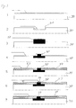
- FIG. 1 shows a sectional view of a partial region of a roller according to the invention, wherein the structure of the roller is shown from the central axis to the surface.
- the exemplified roller is in four sections of width Y, assigned to zones Subdivided A to D, which are each about the same width and about a type area correspond.
- a color-friendly or hydrophobic surface is present Material 25, 33, such as ceramic, copper, polyamide or Rilsan (R) attached with a layer thickness of about 0.3 mm.
- Between the color-friendly material is on the surface color repellent or water friendly material 23, 34, im Example of chromium, with a layer thickness of about 0.02 to 0.05 mm and a Width of about 20 to 24 mm arranged.
- the surface of the invention Roller is therefore designed so that the more of a paper width B for the Pressure corresponding surface alternately a color-friendly material, which assigned to the type area and a water-friendly material, which is between two adjacent color-friendly materials lies, is
- a provided with such a surface dampening drive roller, which in the printing insert is reciprocated in the axial direction with a stroke of, for example, 20 mm, on the one hand ensures that the color-friendly material assigned to the type area ensures the transfer of a color is possible and prevented on the other hand by the between the areas of color-friendly material lying color-repellent or water-friendly Material that turns colors, which in adjacent zones next to each other run, mix.
- the surface area made of water-friendly material Ensures a sufficient supply and discharge of water during operation and thus can remove a color flowing beyond the edge of a zone or a type area mirror and thus can prevent this color in an adjacent zone or a neighboring type area is running.
- FIG. 2 shows a first embodiment of a method according to the invention for the production a roll according to the invention.
- the initial state designated 1 is a WalzenrohSystem or tube 20, which is pre-machined by turning is that four circumferential recesses 21 are generated. Between every two wells 21 is in each case a circumferential projection 22.
- each circumferential projection 22 is chromed and so a layer of chrome 23rd applied.
- a weld 24 attached to to produce a watertight seal at the edge of the chromium layer 23 Prefers
- the weld 24 may be roughened to better adhere to the step 4 to ensure applied color-friendly or hydrophobic coating 25.
- a polyamide can be applied as a color-friendly layer 25. It is possible to perform a plasma coating to the color-friendly layer 25th to create. Likewise, a hard chrome plating can be performed. Becomes advantageous Rilsan applied as color-friendly material 25 on the roller 20.
- the color-friendly Layer can be either as a single layer or in multiple layers - in the embodiment three layers - are applied to the roller 20.
- step 5 the through the processing steps 1 to 4 roller 20 ground or turned to a substantially planar Surface with circumferential color-friendly portions 25 to get which interrupted by circumferential ink-repellent or water-friendly portion 23 or separated from each other.
- FIG. 3 shows method steps for carrying out a second inventive method Process for producing the roll according to the invention.
- step 1 a rolling stock 30 is at the area indicated by the arrow machined by over-turning to the surface of the Walzenrohworkss 30 for the make subsequent manufacturing processes planar. Subsequently, in step 2 a circumferential around the central axis of the Walzenrohworkss 30 recess 31 by piercing or another material-removing process. Subsequently, how in step 3, into the recess 31 formed in step 2 by stainless welding a material 32 applied.
- step 4 by Preturn the surface of the pre-machined by the steps 1 to 3 Walzenroh stresses 30 in a desired shape, wherein the outer surface of the in Step 3 applied material 32 made planar and the width of this material 32nd is reduced to the desired width.
- a color-friendly material 33 such as Rilsan (R) applied to the surface regions of the WalzenrohMechs 30, which at adjoin the projecting portion of the material 32.
- Rilsan R
- one or more layers of color-friendly material 33 may be applied.
- the outer surface of the embedded between the color-friendly material 33 Material 32 is hard chrome plated in step 6 to form an anti-color chrome layer 34 and subsequently the one processed by steps 1 to 6 Roll raw bodies 30 are ground in step 7 to a substantially planar outer surface to obtain.
Abstract
Description
Die vorliegende Erfindung bezieht sich auf eine Walze, insbesondere auf eine Walze, welche in einer Druckmaschine, zum Beispiel im Farb- oder Feuchtwerk verwendet werden kann und auf ein Verfahren zur Herstellung einer solchen Walze.The present invention relates to a roller, in particular a roller, which are used in a printing press, for example in the inking or dampening unit can and on a process for producing such a roller.
Figur 4 zeigt ein Walzenschema eines Druckwerks, durch welches eine zu bedruckende
Bahn B läuft. Die Bahn B wird in der in Figur 4 gezeigten Anordnung zunächst über einen
Gegendruckzylinder 1' geführt, an welchem ein erster Gummizylinder 2' und ein
zweiter Gummizylinder 2" anliegen und wird weiter zur Nachfeuchtung über einen weiteren
Gegendruckzylinder 1 geführt, an welchem ebenfalls ein erster Gummizylinder 2
und ein zweiter Gummizylinder 2" anliegen. Beispielhaft wird das Walzenschema anhand
des zur Nachfeuchtung dienenden Aufbaus des Druckwerkes beschrieben. An dem
an dem Gummizylinder anliegenden Plattenzylinder 3 liegt eine Feuchtauftragwalze 11
an. Die Feuchtauftragwalze 11 steht in Kontakt mit einer Reibwalze 12, dem sogenannten
Feuchtreiber. An dieser Reibwalze 12 liegt die Feucht-Übertragwalze 13 an und erhält
über ein kontaktloses Feuchtwerk das Feuchtmittel aufgesprüht. Die Feucht-Übertragwalze
13, die Reibwalze 12 und die Feucht-Auftragwalze 11 übertragen das
Feuchtmittel auf den Plattenzylinder 3, wodurch man die gewünschte Vor- bzw. Nachfeuchtung
erhält.FIG. 4 shows a roller diagram of a printing unit, through which a printing unit is to be printed
Lane B is running. The web B is first in the arrangement shown in Figure 4 via a
Counter-pressure cylinder 1 'out, at which a first blanket cylinder 2' and a
Die an dem Plattenzylinder 3 anliegenden Farb-Auftragwalzen 4 übertragen Farbe von
der an diesen anliegenden ersten Reibwalze 5a, dem ersten sogenannten Farbreiber. An
dem Farbreiber 5a liegt die Gummiwalze 6a an, welche weiter an einem zweiten Farbreiber
5b anliegt, an welchem zwei weitere Gummiwalzen 6b und 6c anliegen. Die Gummiwalze
6c liegt an der Farbfilmwalze 7 an, an welcher auf bekannte Weise der Farbduktor
8 und die Schöpfwalze 10 anliegen. Der Farbreiber 5a wird über die Gummiwalzen
6a, 6c, den weiteren Farbreiber 5b, über die Farbfilmwalze 7, über den Farbduktor 8,
auf welchem die Farbe über Farbmesser, angeordnet im Farbmesserbalken 9, dosiert wird
und über die Schöpfwalze 10, welche in die Farbe in der Farbwanne eintaucht, in bekannter
Weise eingefärbt.The applied to the
Ein beispielhaftes Farb- und Feuchtwerk ist in der DE 40 12 283 A1 der Anmelderin gezeigt, wobei die Lehre bezüglich des Aufbaus eines Farb- und Feuchtwerks dieser Schrift in diese Anmeldung aufgenommen wird.An exemplary inking and dampening unit is shown in DE 40 12 283 A1 of the applicant, the teaching regarding the structure of a color and dampening of this font is included in this application.
Aus der DE 40 122 83 A1 ist bekannt, dass Reibwalzen eine Oberfläche aus Kupfer haben, um eine farbfreundliche Oberfläche aufzuweisen.From DE 40 122 83 A1 it is known that friction rollers have a surface made of copper, to have a color-friendly interface.
Werden zwei verschiedene Farben auf zwei nebeneinanderliegende Bahnen gedruckt, so
kann es vorkommen, dass der sich hin und her bewegende Feuchtreiber 12 die in zwei
nebeneinanderlaufenden Bahnen verwendeten, unterschiedlichen Farben vermischt, was
zu unbefriedigenden Druckergebnissen führt.If two different colors are printed on two adjacent webs, so
It can happen that the
Es ist eine Aufgabe der vorliegenden Erfindung eine Walze, insbesondere für eine Druckmaschine vorzuschlagen, welche ein Vermischen von Farben bei nebeneinanderlaufenden Bahnen verringert oder verhindert.It is an object of the present invention to provide a roller, in particular for a roller To propose a printing press, which mixing colors in juxtaposed Reduced or prevented tracks.
Diese Aufgabe wird durch eine Walze gemäß Patentanspruch 1 gelöst. Vorteilhafte Ausführungsformen
ergeben sich aus den Unteransprüchen.This object is achieved by a roller according to
Bevorzugt wird die erfindungsgemäße Walze in der Nachfeuchtung eingesetzt, bei welcher die Gefahr besteht, dass Farbe in das Feuchtwerk zurückläuft.Preferably, the roll according to the invention is used in the re-wetting, in which the danger exists that paint runs back into the dampening unit.
Die erfindungsgemäße Walze weist mindestens zwei bevorzugt um die Mittelachse der Walze umlaufende Teilbereiche oder Flächen auf, welche aus einem farbfreundlichen Material bestehen, wobei zwischen den zwei umlaufenden Teilbereichen oder Flächen aus farbfreundlichem Material mindestens ein umlaufender Teilbereich bzw. eine umlaufende Fläche angeordnet ist, welche aus einem farbabstoßenden oder farbabweisenden Material besteht. Unter den Begriffen "umlaufender Teilbereich" oder "umlaufende Fläche" soll im Sinn dieser Anmeldung ein Bereich einer Oberfläche einer Walze verstanden werden, welcher sich vollständig oder teilweise um den Umfang der Walze erstreckt. Eine umlaufende Fläche kann zum Beispiel ringförmig ausgebildet sein oder einen oder mehrere Teilringstücke aufweisen, wobei die Oberfläche vorteilhaft entsprechend der Walzenoberfläche ausgebildet ist und bevorzugt um die Mittelachse der Walze herum angeordnet ist und besonders vorteilhaft etwa die gleiche Krümmung aufweist wie die Krümmung der benachbarten Walzenoberfläche. Erfindungsgemäß sind somit nach einer Ausführungsform in axialer Richtung einer Walze eine erste umlaufende Fläche oder ein ringförmiges Element aus einem farbfreundlichen Material, ein daran anschließendes ringförmiges Element aus einem farbabstoßenden oder farbabweisenden Material und daran anschließend ein zweites ringförmiges Element aus einem farbfreundlichen Material angeordnet, wodurch die beiden ringförmigen Elemente aus farbfreundlichem Material durch das ringförmige Element aus farbabstoßendem Material getrennt sind.The roller according to the invention has at least two preferably around the central axis of Roller peripheral portions or surfaces on which of a color-friendly Material consist, being between the two circumferential sections or areas made of color-friendly material at least one circumferential portion or a circumferential Surface is arranged, which consists of an ink-repellent or color-repellent Material exists. Under the terms "circumferential section" or "circumferential surface" should be understood in the context of this application, an area of a surface of a roller which extends completely or partially around the circumference of the roller. A circumferential surface may, for example, be annular or one or have a plurality of partial ring pieces, wherein the surface advantageously according to Roller surface is formed and preferably around the central axis of the roller around is arranged and particularly advantageous about the same curvature as the Curvature of the adjacent roll surface. According to the invention are thus after a Embodiment in the axial direction of a roller, a first circumferential surface or a annular element of a color-friendly material, an adjoining annular element made of an ink-repellent or color-repellent material and followed by a second annular element made of a color-friendly material arranged, whereby the two annular elements from color-friendly material separated by the annular element of ink repellent material.
Ein im Sinne der Erfindung "farbfreundliches" Material soll zum Beispiel solche physikalischen und/oder chemischen Eigenschaften aufweisen, dass eine mit einem solchen Material beschichte Walze die Funktion als Farbwalze erfüllen kann, also Farbe aufnehmen kann. Bevorzugt weist ein farbfreundliches Material eine hydrophobe Eigenschaft auf. Entsprechend soll ein im Sinne der Erfindung "farbabstoßendes" oder "farbabweisendes" Material ein Material sein, welches solche physikalischen und/oder chemischen Eigenschaften aufweist, dass die Walze in einem mit einem farbabstoßenden Material beschichteten Bereich eine Funktion als Feuchtwalze erfüllen kann, also Wasser aufnehmen kann. Bevorzugt soll das farbabstoßende Material hydrophile Eigenschaften haben oder wasserfreundlich sein.A "color-friendly" in the context of the invention, for example, such physical and / or have chemical properties that one with such Material coated roller can fulfill the function as a paint roller, so take color can. Preferably, a color-friendly material has a hydrophobic property on. Accordingly, an "ink-repellent" or "ink-repellent" in the context of the invention Material may be a material containing such physical and / or chemical Features that roll in one with an ink repellent material coated area can perform a function as a dampener, so absorb water can. Preferably, the ink repellent material should have hydrophilic properties or be water friendly.
Bevorzugt wird als farbfreundliches oder hydrophobes Material eine Keramik, Kupfer, Polyamid oder Rilsan (R) verwendet. Preferred as color-friendly or hydrophobic material is a ceramic, copper, Polyamide or Rilsan (R) used.
Vorteilhaft wird als farbabstoßendes bzw. wasserfreundliches oder hydrophiles Material Chrom verwendet.It is advantageous as an ink-repellent or water-friendly or hydrophilic material Chrome used.
Verschiedene farbfreundliche und farbabstoßende Materialien sind im Stand der Technik bekannt. Beispielhaft wird auf die Lehren der EP 0 203 342 A2 und der DE 196 53 911 A1 verwiesen, deren Offenbarung bezüglich Materialien zur Beschichtung von Oberflächen von Walzen in diese Anmeldung aufgenommen wird.Various color-friendly and color-repellent materials are known in the art known. By way of example, the teachings of EP 0 203 342 A2 and of DE 196 53 911 A1, whose disclosure regarding materials for coating of surfaces of rolls is included in this application.
Vorteilhaft sind an einer erfindungsgemäßen Walze in axialer Richtung hintereinander mehrere Bereiche oder umlaufende Flächen aus farbfreundlichem Material angeordnet, zwischen welchen jeweils mindestens ein Bereich oder eine umlaufende Fläche aus einem farbabstoßenden oder wasserfreundlichen Material angeordnet ist. So können bei einer Walze gemäß einer Ausführungsform zum Beispiel vier farbfreundliche Teilbereiche in axialer Richtung aufeinanderfolgend vorgesehen sein, welche durch drei Teilbereiche aus wasserfreundlichem oder farbabweisendem Material voneinander getrennt sind.It is advantageous for a roll according to the invention in the axial direction one behind the other arranged several areas or circumferential surfaces of color-friendly material, between which in each case at least one region or a circumferential surface of a color-repellent or water-friendly material is arranged. So can at a roller according to an embodiment, for example, four color-friendly sections be provided in succession in the axial direction, which by three sections separated from water-friendly or color-repellent material are.
Die Dicke des farbfreundlichen Materials liegt bevorzugt in dem Bereich von 0,1 mm bis 0,5 mm und beträgt besonders bevorzugt 0,3 mm. Vorteilhaft liegt die Dicke des farbabweisenden oder wasserfreundlichen Materials im Bereich von 0,01 mm bis 0,10 mm, weiter bevorzugt im Bereich von 0,02 mm bis 0,05 mm und beträgt vorteilhaft 0,035 mm.The thickness of the color-friendly material is preferably in the range of 0.1 mm to 0.5 mm, and is more preferably 0.3 mm. Advantageously, the thickness of the ink-repellent or water-friendly material in the range of 0.01 mm to 0.10 mm, more preferably in the range of 0.02 mm to 0.05 mm and is advantageously 0.035 mm.
Die Breite einer umlaufenden Fläche oder eines Teilbereichs aus farbfreundlichem Material ist bevorzugt etwa die Breite eines Satzspiegels und liegt vorteilhaft im Bereich von 25 bis 35 cm. Bevorzugt ist die Breite des Teilbereichs aus wasserfreundlichem Material etwas größer als der Hub einer Reiberwalze und liegt vorteilhaft im Bereich von 18 bis 26 mm und beträgt vorteilhaft 22 mm. The width of a circumferential area or part of color-friendly material is preferably about the width of a sentence mirror and is advantageously in the range of 25 to 35 cm. Preferably, the width of the portion of water-friendly material slightly larger than the stroke of a distributor roller and is advantageously in the range of 18 to 26 mm and is advantageously 22 mm.
Gemäß einem weiteren Aspekt bezieht sich die Erfindung auf ein Farb- und/oder Feuchtwerk bevorzugt für Offset-Druckmaschinen mit mindestens einer wie oben beschriebenen Walze.According to a further aspect, the invention relates to a color and / or Dampening unit preferred for offset printing machines with at least one as described above Roller.
Nach einem weiteren Aspekt bezieht sich die Erfindung auf ein Verfahren zur Herstellung einer wie oben beschriebenen Walze, wobei an einem Walzenrohkörper mindestens zwei etwa ringförmige oder teilringförmige Strukturen aus einem farbfreundlichen Material und dazwischen liegend mindestens eine ringförmige Struktur aus einem farbabstoβenden Material im Oberflächenbereich oder unmittelbar an der Oberfläche der Walze ausgebildet, also zum Beispiel freigelegt, angebracht oder darauf beschichtet werden.In another aspect, the invention relates to a method of manufacture a roller as described above, wherein on a Walzenrohkörper at least two approximately annular or partially annular structures made of a color-friendly material and intervening there is at least one annular structure of a color-repellent Material in the surface area or directly on the surface of the roller trained, so for example exposed, attached or coated on it.
Vorteilhaft wird die erfindungsgemäße Walze hergestellt, indem ein Walzenrohkörper oder Rohr durch Drehen vorbearbeitet wird, um eine Oberfläche mit einer gewünschten Beschaffenheit zu erhalten. In dem Walzenrohkörper können gemäß einer Ausführungsform schon ein oder mehrere Teilbereiche aus farbfreundlichem und farbabstoßendem bzw. farbabweisendes Material vorgesehen sein. Es ist auch möglich, dass ein farbfreundliches oder farbabstoßendes Material auf den Walzenrohkörper an den gewünschten Stellen aufgebracht wird. Das Aufbringen eines farbfreundlichen oder farbabstoßenden Materials kann zum Beispiel durch Verchromen, Aufschweißen oder durch ein Beschichtungsverfahren, wie zum Beispiel eine Plasmabeschichtung durchgeführt werden. Vorteilhaft kann ein Bereich am Übergang zwischen farbfreundlichen und farbabstoßenden oder -abweisenden Materialien oder ein Randbereich versiegelt werden, um zum Beispiel ein Eindringen von Feuchtigkeit in die Walze zu verhindern. Nach dem Aufbringen und/oder Freilegen und/oder Nachbearbeiten der Materialien aus farbfreundlichem und/oder farbabstoßendem Material kann eine Nachbearbeitung der so hergestellten Walze durch Drehen oder Überschleifen durchgeführt werden, um eine Walze zu erhalten, welche zum Beispiel in einem Farb- oder Feuchtwerk einer Druckmaschine eingesetzt werden kann.Advantageously, the roll according to the invention is produced by a roll raw body or pipe is pre-machined by turning to a surface with a desired To get texture. In the Walzenrohkörper can according to one embodiment already one or more parts of color-friendly and farbabstoßendem or color-repellent material may be provided. It is also possible that a color-friendly or ink-repellent material on the Walzenrohkörper to the desired Jobs is applied. The application of a color-friendly or color-repellent Material can be, for example, by chromium plating, welding or by a coating process, such as plasma coating. Advantageously, an area at the transition between color-friendly and color-repellent or repellent materials or a border area to be sealed to Example to prevent moisture from entering the roller. After application and / or exposing and / or reworking the materials from color friendly and / or ink-repellent material may be a post-processing of the thus produced Roller can be performed by turning or grinding to a roller obtained, for example, in a paint or dampening unit of a printing press can be used.
Die Erfindung wird nachfolgend anhand bevorzugter Ausführungsbeispiele beschrieben werden: The invention will be described below with reference to preferred embodiments become:
Es zeigen:
Figur 1- Eine schematische Schnittansicht eines Teilbereiches einer erfindungsgemäßen Walze;
Figur 2- Ein erstes Ausführungsbeispiel eines erfindungsgemäßen Verfahrens zum Herstellen einer Walze;
Figur 3- Ein zweites Ausführungsbeispiel eines erfindungsgemäßen Verfahrens zum Herstellen einer Walze; und
Figur 4- Ein Walzenschema zur Erläuterung des Einsatzes einer erfindungsgemäßen Walze.
- FIG. 1
- A schematic sectional view of a portion of a roll according to the invention;
- FIG. 2
- A first embodiment of a method according to the invention for producing a roll;
- FIG. 3
- A second embodiment of a method according to the invention for producing a roll; and
- FIG. 4
- A roller diagram for explaining the use of a roller according to the invention.
Figur 1 zeigt in einer Schnittansicht einen Teilbereich einer erfindungsgemäßen Walze,
wobei der Aufbau der Walze von der Mittelachse zur Oberfläche hin dargestellt ist. Die
beispielhaft dargestellte Walze ist in vier Abschnitte der Breite Y, zugeordnet zu Zonen
A bis D unterteilt, welche jeweils in etwa gleich breit sind und in etwa einem Satzspiegel
entsprechen. In den Zonen A bis D ist an der Oberfläche ein farbfreundliches oder hydrophobes
Material 25, 33, wie zum Beispiel Keramik, Kupfer, Polyamid oder Rilsan (R)
mit einer Schichtdicke von ca. 0,3 mm angebracht. Zwischen dem farbfreundlichen Material
ist an der Oberfläche farbabstoßendes oder wasserfreundliches Material 23, 34, im
Ausführungsbeispiel Chrom, mit einer Schichtdicke von etwa 0,02 bis 0,05 mm und einer
Breite von etwa 20 bis 24 mm angeordnet. Die Oberfläche der erfindungsgemäßen
Walze ist demzufolge so ausgestaltet, dass über die eher einer Papierbreite B für den
Druck entsprechende Oberfläche abwechselnd ein farbfreundliches Material, welches
dem Satzspiegel zugeordnet ist und ein wasserfreundliches Material, welches zwischen
zwei benachbarten farbfreundlichen Materialien liegt, angeordnet ist.FIG. 1 shows a sectional view of a partial region of a roller according to the invention,
wherein the structure of the roller is shown from the central axis to the surface. The
exemplified roller is in four sections of width Y, assigned to zones
Subdivided A to D, which are each about the same width and about a type area
correspond. In zones A to D, a color-friendly or hydrophobic surface is
Eine mit einer solchen Oberfläche versehene Feuchtreiberwalze, welche im Druckeinsatz mit einem Hub von beispielsweise 20 mm in axialer Richtung hin- und herbewegt wird, stellt einerseits sicher, dass durch das dem Satzspiegel zugeordnete farbfreundliche Material das Übertragen einer Farbe möglich ist und verhindert andererseits durch das zwischen den Bereichen aus farbfreundlichem Material liegende farbabstoßende oder wasserfreundliche Material, dass sich Farben, welche in benachbarten Zonen nebeneinander laufen, vermischen können. Der Oberflächenbereich aus wasserfreundlichem Material stellt im Betrieb eine ausreichende Zu- und Abfuhr von Wasser sicher und kann somit eine über den Rand einer Zone bzw. eines Satzspiegels hinausfließende Farbe abtransportieren und kann somit verhindern, dass diese Farbe in eine benachbarte Zone oder einen benachbarten Satzspiegel läuft.A provided with such a surface dampening drive roller, which in the printing insert is reciprocated in the axial direction with a stroke of, for example, 20 mm, on the one hand ensures that the color-friendly material assigned to the type area ensures the transfer of a color is possible and prevented on the other hand by the between the areas of color-friendly material lying color-repellent or water-friendly Material that turns colors, which in adjacent zones next to each other run, mix. The surface area made of water-friendly material Ensures a sufficient supply and discharge of water during operation and thus can remove a color flowing beyond the edge of a zone or a type area mirror and thus can prevent this color in an adjacent zone or a neighboring type area is running.
Figur 2 zeigt eine erste Ausführungsform eines erfindungsgemäßen Verfahrens zur Herstellung
einer erfindungsgemäßen Walze. In dem mit 1 bezeichneten Ausgangszustand
liegt ein Walzenrohkörper oder Rohr 20 vor, welches durch Drehen so vorbearbeitet
wird, dass vier umlaufende Vertiefungen 21 erzeugt werden. Zwischen jeweils zwei Vertiefungen
21 befindet sich jeweils ein umlaufender Vorsprung 22.FIG. 2 shows a first embodiment of a method according to the invention for the production
a roll according to the invention. In the initial state designated 1
is a Walzenrohkörper or
In Schritt 2 wird jeder umlaufende Vorsprung 22 verchromt und so eine Lage Chrom 23
aufgebracht.In
Als nächstes wird an den mit 24 gekennzeichneten Übergängen zwischen dem aufgebrachten
Chrom 23 und dem Walzenrohkörper 20 eine Schweißnaht 24 angebracht, um
eine wasserdichte Versiegelung am Rand der Chromschicht 23 herzustellen. Bevorzugt
kann die Schweißnaht 24 aufgeraut werden, um ein besseres Anhaften der im Schritt 4
aufzubringenden farbfreundlichen oder hydrophoben Beschichtung 25 zu gewährleisten.Next, at the transitions marked 24, between the applied
Beispielsweise kann ein Polyamid als farbfreundliche Schicht 25 aufgebracht werden. Es
ist möglich eine Plasmabeschichtung durchzuführen, um die farbfreundliche Schicht 25
zu erzeugen. Ebenso kann eine Hartverchromung durchgeführt werden. Vorteilhaft wird
Rilsan als farbfreundliches Material 25 auf die Walze 20 aufgebracht. Die farbfreundliche
Schicht kann entweder als einzelne Lage oder in mehreren Lagen - im Ausführungsbeispiel
drei Lagen - auf die Walze 20 aufgebracht werden. For example, a polyamide can be applied as a color-
Abschließend kann, wie in Schritt 5 gezeigt, die durch die Bearbeitungsschritte 1 bis 4
hergestellte Walze 20 überschliffen oder gedreht werden, um eine im Wesentlichen planare
Oberfläche mit umlaufenden farbfreundlichen Teilbereichen 25 zu erhalten, welche
durch umlaufende farbabweisende oder wasserfreundliche Teilbereich 23 unterbrochen
bzw. voneinander getrennt werden.Finally, as shown in
Figur 3 zeigt Verfahrensschritte zur Durchführung eines zweiten erfindungsgemäßen Verfahrens zur Herstellung der erfindungsgemäßen Walze.FIG. 3 shows method steps for carrying out a second inventive method Process for producing the roll according to the invention.
Bei Schritt 1 wird ein Walzenrohkörper 30 bei der durch den Pfeil gekennzeichneten Fläche
durch Überdrehen bearbeitet, um die Oberfläche des Walzenrohkörpers 30 für das
nachfolgende Herstellungsverfahren planar zu machen. Anschließend wird in Schritt 2
eine um die Mittelachse des Walzenrohkörpers 30 umlaufende Vertiefung 31 durch Einstechen
oder ein anderes materialabhebendes Verfahren erzeugt. Anschließend wird, wie
in Schritt 3 gezeigt, in die in Schritt 2 ausgebildete Vertiefung 31 durch rostfreies Aufschweißen
ein Material 32 aufgebracht. Nachfolgend wird, wie in Schritt 4 gezeigt, durch
Vordrehen die Oberfläche des durch die Schritte 1 bis 3 vorbearbeiteten Walzenrohkörpers
30 in eine gewünschte Form gebracht, wobei die außenliegende Oberfläche des in
Schritt 3 aufgebrachten Materials 32 planar gemacht und die Breite dieses Materials 32
auf die gewünschte Breite verkleinert wird.In
Im nachfolgenden Schritt 5 wird ein farbfreundliches Material 33, wie zum Beispiel Rilsan
(R) auf die Oberflächenbereiche des Walzenrohkörpers 30 aufgebracht, welche an
den vorstehenden Bereich des Materials 32 angrenzen. Wie oben bei Figur 2 beschrieben,
können eine oder mehrere Schichten des farbfreundlichen Materials 33 aufgebracht werden.
Die außenliegende Oberfläche des zwischen dem farbfreundlichen Material 33 eingebetteten
Materials 32 wird in Schritt 6 hartverchromt, um eine farbabweisende Chromschicht
34 aufzubringen und nachfolgend wird der durch die Schritte 1 bis 6 bearbeitete
Walzenrohkörper 30 in Schritt 7 überschliffen, um eine im Wesentlichen planare Außenoberfläche
zu erhalten. In the
Obwohl in den Figuren 2 und 3 Ausführungsbeispiele zur Herstellung von Walzen bzw. Walzenoberflächen mit vier bzw. zwei Teilbereichen aus farbfreundlichem Material gezeigt sind, können diese Verfahren zur Herstellung einer beliebigen Anzahl von Beschichtungen von Walzen mit farbfreundlichen und farbabweisenden Oberflächen verwendet werden.Although in the figures 2 and 3 embodiments for the production of rolls or Roll surfaces with four or two sections of color-friendly material shown These methods can be used to make any number of coatings used by rollers with color-friendly and ink-repellent surfaces become.
Claims (11)
Applications Claiming Priority (2)
| Application Number | Priority Date | Filing Date | Title |
|---|---|---|---|
| DE10316240 | 2003-04-09 | ||
| DE10316240A DE10316240A1 (en) | 2003-04-09 | 2003-04-09 | Roller for a printing machine and method for producing a roller |
Publications (3)
| Publication Number | Publication Date |
|---|---|
| EP1466729A2 true EP1466729A2 (en) | 2004-10-13 |
| EP1466729A3 EP1466729A3 (en) | 2008-12-10 |
| EP1466729B1 EP1466729B1 (en) | 2010-08-04 |
Family
ID=32864400
Family Applications (1)
| Application Number | Title | Priority Date | Filing Date |
|---|---|---|---|
| EP04405171A Expired - Lifetime EP1466729B1 (en) | 2003-04-09 | 2004-03-22 | Cylinder for a printing machine and process for producing of cylinder |
Country Status (4)
| Country | Link |
|---|---|
| US (1) | US7127990B2 (en) |
| EP (1) | EP1466729B1 (en) |
| AT (1) | ATE476295T1 (en) |
| DE (2) | DE10316240A1 (en) |
Cited By (2)
| Publication number | Priority date | Publication date | Assignee | Title |
|---|---|---|---|---|
| WO2009098102A1 (en) * | 2008-02-07 | 2009-08-13 | Manroland Ag | Printing press for a processing machine |
| CN108430776A (en) * | 2015-11-27 | 2018-08-21 | 捷德货币技术有限责任公司 | Anilox roll for flexographic presses |
Families Citing this family (4)
| Publication number | Priority date | Publication date | Assignee | Title |
|---|---|---|---|---|
| US7207268B2 (en) * | 2004-07-30 | 2007-04-24 | Nu Tech Coatings Llc | Apparatus and method of enhancing printing press cylinders |
| DE102006015490B4 (en) * | 2006-04-03 | 2009-11-12 | Koenig & Bauer Aktiengesellschaft | Web-fed printing machine with a film inking unit |
| US20080134916A1 (en) * | 2006-12-07 | 2008-06-12 | Heidelberger Druckmaschinen Ag | Printing Press with a Washing Device for an Inking Unit and Method of Removing Ink from an Inking Unit |
| US8192005B2 (en) * | 2009-07-29 | 2012-06-05 | Xerox Corporation | Rollers for phase-change ink printing |
Citations (2)
| Publication number | Priority date | Publication date | Assignee | Title |
|---|---|---|---|---|
| US4860652A (en) | 1986-05-24 | 1989-08-29 | Kabushikigaisha Tokyo Kikai Seisakusho | Mesh roller for planography |
| EP0511543A1 (en) | 1991-04-27 | 1992-11-04 | KOENIG & BAUER-ALBERT AKTIENGESELLSCHAFT | Roller for a printing machine |
Family Cites Families (10)
| Publication number | Priority date | Publication date | Assignee | Title |
|---|---|---|---|---|
| US4287827A (en) * | 1979-05-17 | 1981-09-08 | Warner Gordon R | Combined inking and moistening roller |
| DE3326698A1 (en) * | 1983-07-23 | 1985-02-07 | Heidelberger Druckmaschinen Ag, 6900 Heidelberg | DEVICE FOR ZONE-WAY MEASURING CONTROL OF THE DAMPING AGENT IN THE PRINTING PLANT OF AN OFFSET PRINTING MACHINE |
| DE3519134C1 (en) | 1985-05-29 | 1988-10-20 | Roland Man Druckmasch | Roller, in particular ink roller or distributor roller, for printing machines and their use |
| US5107762A (en) * | 1988-06-16 | 1992-04-28 | Rockwell International Corporation | Inked dampener for lithographic printing |
| DE4012283A1 (en) * | 1990-04-17 | 1991-10-24 | Wifag Maschf | Inking and moistening mechanism for reversible printing press |
| US6435086B1 (en) * | 1995-05-04 | 2002-08-20 | Howard W. DeMoore | Retractable inking/coating apparatus having ferris movement between printing units |
| DE19653911C2 (en) | 1996-12-21 | 2003-03-27 | Roland Man Druckmasch | Printing machine roller with a color-friendly coating on the roll surface of the roller core, in particular ink roller |
| DE19926833A1 (en) * | 1999-06-12 | 2000-12-14 | Koenig & Bauer Ag | Bridge roller has surface with hydrophilic and oleophilic particles, damp application roller, and form cylinder |
| EP1147889A3 (en) * | 2000-04-14 | 2006-01-18 | Komori Corporation | Roller structure in printing press |
| FI116389B (en) * | 2002-07-16 | 2005-11-15 | Millidyne Oy | Procedure for adjusting surface properties |
-
2003
- 2003-04-09 DE DE10316240A patent/DE10316240A1/en not_active Withdrawn
-
2004
- 2004-03-22 DE DE502004011465T patent/DE502004011465D1/en not_active Expired - Lifetime
- 2004-03-22 EP EP04405171A patent/EP1466729B1/en not_active Expired - Lifetime
- 2004-03-22 AT AT04405171T patent/ATE476295T1/en active
- 2004-04-08 US US10/820,489 patent/US7127990B2/en not_active Expired - Fee Related
Patent Citations (2)
| Publication number | Priority date | Publication date | Assignee | Title |
|---|---|---|---|---|
| US4860652A (en) | 1986-05-24 | 1989-08-29 | Kabushikigaisha Tokyo Kikai Seisakusho | Mesh roller for planography |
| EP0511543A1 (en) | 1991-04-27 | 1992-11-04 | KOENIG & BAUER-ALBERT AKTIENGESELLSCHAFT | Roller for a printing machine |
Cited By (2)
| Publication number | Priority date | Publication date | Assignee | Title |
|---|---|---|---|---|
| WO2009098102A1 (en) * | 2008-02-07 | 2009-08-13 | Manroland Ag | Printing press for a processing machine |
| CN108430776A (en) * | 2015-11-27 | 2018-08-21 | 捷德货币技术有限责任公司 | Anilox roll for flexographic presses |
Also Published As
| Publication number | Publication date |
|---|---|
| US20040226461A1 (en) | 2004-11-18 |
| EP1466729A3 (en) | 2008-12-10 |
| DE502004011465D1 (en) | 2010-09-16 |
| ATE476295T1 (en) | 2010-08-15 |
| EP1466729B1 (en) | 2010-08-04 |
| DE10316240A1 (en) | 2004-11-04 |
| US7127990B2 (en) | 2006-10-31 |
Similar Documents
| Publication | Publication Date | Title |
|---|---|---|
| EP0324939B1 (en) | Engraved roller for an offset inking unit and process for manufacturing such an engraved roller | |
| EP2703162B1 (en) | Method and device for printing printed material | |
| EP0486855B2 (en) | Engraved roller | |
| EP0197374B1 (en) | Printing roller and a method of manufacturing the surface of a printing roller | |
| DE3109964A1 (en) | "COLLECTIVE PRINTING MACHINE PRINTER FOR SECURITIES PRINTING" | |
| EP0287002B1 (en) | Engraved roller for an offset inking device, and manufacturing method for such an engraved roller | |
| EP2040931B1 (en) | Stochastically lasered film roller | |
| EP2242651A2 (en) | Rotary flat-bed printing machine | |
| DE3004295A1 (en) | FLUID ROLLER | |
| EP1908589A2 (en) | Printing unit of a printing press | |
| EP1466729B1 (en) | Cylinder for a printing machine and process for producing of cylinder | |
| WO1991013761A1 (en) | Short inking apparatus for a rotary press | |
| DE102004005578A1 (en) | Device and method for controlling the fluid supply | |
| DE102008007679B4 (en) | Printing unit for a processing machine | |
| EP2377686B1 (en) | Sleeve for mounting on a printing press cylinder | |
| DE19817104A1 (en) | Gravure printing roller surfaced with oil-resistant, water-repellent rubber | |
| WO2009097982A1 (en) | Printing press for a processing machine | |
| DE202004006800U1 (en) | Print roller has print zones separated by grooves with profiled edges and with profiled end shoulders to prevent lateral spread of ink into grooves | |
| DE102004011882A1 (en) | Printing blanket for printers has dimensionally stable support plate fixed by ends on transfer cylinder and with indentation formed between ends of blanket | |
| DE202008004977U1 (en) | High-pressure roller | |
| EP2576221B1 (en) | Rotary printing machine having a forme cylinder and an inking unit positioned on said form cylinder | |
| DE102010007648A1 (en) | Inking system for use in offset printing machine to ink printing plate, has outer surface transferred with structured ink, where surface includes surface profile in circumferential direction and in direction of rotation axis in sub areas | |
| DE102004023316A1 (en) | Printing blanket for printers has dimensionally stable support plate fixed by ends on transfer cylinder and with indentation formed between ends of blanket | |
| EP1577093A1 (en) | Cleaning device for a rotationally symmetric part in a processing machine | |
| WO2006056323A1 (en) | Gravure printing unit with a doctor for the printing cylinder gravure printing machine and method for exchange of a printing cylinder |
Legal Events
| Date | Code | Title | Description |
|---|---|---|---|
| PUAI | Public reference made under article 153(3) epc to a published international application that has entered the european phase |
Free format text: ORIGINAL CODE: 0009012 |
|
| AK | Designated contracting states |
Kind code of ref document: A2 Designated state(s): AT BE BG CH CY CZ DE DK EE ES FI FR GB GR HU IE IT LI LU MC NL PL PT RO SE SI SK TR |
|
| AX | Request for extension of the european patent |
Extension state: AL LT LV MK |
|
| RAP1 | Party data changed (applicant data changed or rights of an application transferred) |
Owner name: WIFAG MASCHINENFABRIK AG |
|
| PUAL | Search report despatched |
Free format text: ORIGINAL CODE: 0009013 |
|
| AK | Designated contracting states |
Kind code of ref document: A3 Designated state(s): AT BE BG CH CY CZ DE DK EE ES FI FR GB GR HU IE IT LI LU MC NL PL PT RO SE SI SK TR |
|
| AX | Request for extension of the european patent |
Extension state: AL LT LV MK |
|
| 17P | Request for examination filed |
Effective date: 20081218 |
|
| 17Q | First examination report despatched |
Effective date: 20090317 |
|
| AKX | Designation fees paid |
Designated state(s): AT BE BG CH CY CZ DE DK EE ES FI FR GB GR HU IE IT LI LU MC NL PL PT RO SE SI SK TR |
|
| GRAP | Despatch of communication of intention to grant a patent |
Free format text: ORIGINAL CODE: EPIDOSNIGR1 |
|
| GRAS | Grant fee paid |
Free format text: ORIGINAL CODE: EPIDOSNIGR3 |
|
| GRAA | (expected) grant |
Free format text: ORIGINAL CODE: 0009210 |
|
| AK | Designated contracting states |
Kind code of ref document: B1 Designated state(s): AT BE BG CH CY CZ DE DK EE ES FI FR GB GR HU IE IT LI LU MC NL PL PT RO SE SI SK TR |
|
| REG | Reference to a national code |
Ref country code: GB Ref legal event code: FG4D Free format text: NOT ENGLISH |
|
| REG | Reference to a national code |
Ref country code: CH Ref legal event code: EP |
|
| REG | Reference to a national code |
Ref country code: IE Ref legal event code: FG4D Free format text: LANGUAGE OF EP DOCUMENT: GERMAN |
|
| REF | Corresponds to: |
Ref document number: 502004011465 Country of ref document: DE Date of ref document: 20100916 Kind code of ref document: P |
|
| REG | Reference to a national code |
Ref country code: NL Ref legal event code: VDEP Effective date: 20100804 |
|
| PG25 | Lapsed in a contracting state [announced via postgrant information from national office to epo] |
Ref country code: NL Free format text: LAPSE BECAUSE OF FAILURE TO SUBMIT A TRANSLATION OF THE DESCRIPTION OR TO PAY THE FEE WITHIN THE PRESCRIBED TIME-LIMIT Effective date: 20100804 Ref country code: FI Free format text: LAPSE BECAUSE OF FAILURE TO SUBMIT A TRANSLATION OF THE DESCRIPTION OR TO PAY THE FEE WITHIN THE PRESCRIBED TIME-LIMIT Effective date: 20100804 |
|
| PG25 | Lapsed in a contracting state [announced via postgrant information from national office to epo] |
Ref country code: CY Free format text: LAPSE BECAUSE OF FAILURE TO SUBMIT A TRANSLATION OF THE DESCRIPTION OR TO PAY THE FEE WITHIN THE PRESCRIBED TIME-LIMIT Effective date: 20100804 Ref country code: BG Free format text: LAPSE BECAUSE OF FAILURE TO SUBMIT A TRANSLATION OF THE DESCRIPTION OR TO PAY THE FEE WITHIN THE PRESCRIBED TIME-LIMIT Effective date: 20101104 Ref country code: SI Free format text: LAPSE BECAUSE OF FAILURE TO SUBMIT A TRANSLATION OF THE DESCRIPTION OR TO PAY THE FEE WITHIN THE PRESCRIBED TIME-LIMIT Effective date: 20100804 Ref country code: PT Free format text: LAPSE BECAUSE OF FAILURE TO SUBMIT A TRANSLATION OF THE DESCRIPTION OR TO PAY THE FEE WITHIN THE PRESCRIBED TIME-LIMIT Effective date: 20101206 Ref country code: PL Free format text: LAPSE BECAUSE OF FAILURE TO SUBMIT A TRANSLATION OF THE DESCRIPTION OR TO PAY THE FEE WITHIN THE PRESCRIBED TIME-LIMIT Effective date: 20100804 |
|
| REG | Reference to a national code |
Ref country code: IE Ref legal event code: FD4D |
|
| PG25 | Lapsed in a contracting state [announced via postgrant information from national office to epo] |
Ref country code: SE Free format text: LAPSE BECAUSE OF FAILURE TO SUBMIT A TRANSLATION OF THE DESCRIPTION OR TO PAY THE FEE WITHIN THE PRESCRIBED TIME-LIMIT Effective date: 20100804 Ref country code: GR Free format text: LAPSE BECAUSE OF FAILURE TO SUBMIT A TRANSLATION OF THE DESCRIPTION OR TO PAY THE FEE WITHIN THE PRESCRIBED TIME-LIMIT Effective date: 20101105 |
|
| PG25 | Lapsed in a contracting state [announced via postgrant information from national office to epo] |
Ref country code: IE Free format text: LAPSE BECAUSE OF FAILURE TO SUBMIT A TRANSLATION OF THE DESCRIPTION OR TO PAY THE FEE WITHIN THE PRESCRIBED TIME-LIMIT Effective date: 20100804 Ref country code: DK Free format text: LAPSE BECAUSE OF FAILURE TO SUBMIT A TRANSLATION OF THE DESCRIPTION OR TO PAY THE FEE WITHIN THE PRESCRIBED TIME-LIMIT Effective date: 20100804 |
|
| PG25 | Lapsed in a contracting state [announced via postgrant information from national office to epo] |
Ref country code: CZ Free format text: LAPSE BECAUSE OF FAILURE TO SUBMIT A TRANSLATION OF THE DESCRIPTION OR TO PAY THE FEE WITHIN THE PRESCRIBED TIME-LIMIT Effective date: 20100804 Ref country code: IT Free format text: LAPSE BECAUSE OF FAILURE TO SUBMIT A TRANSLATION OF THE DESCRIPTION OR TO PAY THE FEE WITHIN THE PRESCRIBED TIME-LIMIT Effective date: 20100804 Ref country code: RO Free format text: LAPSE BECAUSE OF FAILURE TO SUBMIT A TRANSLATION OF THE DESCRIPTION OR TO PAY THE FEE WITHIN THE PRESCRIBED TIME-LIMIT Effective date: 20100804 Ref country code: SK Free format text: LAPSE BECAUSE OF FAILURE TO SUBMIT A TRANSLATION OF THE DESCRIPTION OR TO PAY THE FEE WITHIN THE PRESCRIBED TIME-LIMIT Effective date: 20100804 Ref country code: EE Free format text: LAPSE BECAUSE OF FAILURE TO SUBMIT A TRANSLATION OF THE DESCRIPTION OR TO PAY THE FEE WITHIN THE PRESCRIBED TIME-LIMIT Effective date: 20100804 |
|
| PLBE | No opposition filed within time limit |
Free format text: ORIGINAL CODE: 0009261 |
|
| STAA | Information on the status of an ep patent application or granted ep patent |
Free format text: STATUS: NO OPPOSITION FILED WITHIN TIME LIMIT |
|
| PG25 | Lapsed in a contracting state [announced via postgrant information from national office to epo] |
Ref country code: ES Free format text: LAPSE BECAUSE OF FAILURE TO SUBMIT A TRANSLATION OF THE DESCRIPTION OR TO PAY THE FEE WITHIN THE PRESCRIBED TIME-LIMIT Effective date: 20101115 |
|
| 26N | No opposition filed |
Effective date: 20110506 |
|
| PGFP | Annual fee paid to national office [announced via postgrant information from national office to epo] |
Ref country code: CH Payment date: 20110620 Year of fee payment: 8 |
|
| REG | Reference to a national code |
Ref country code: DE Ref legal event code: R097 Ref document number: 502004011465 Country of ref document: DE Effective date: 20110506 |
|
| BERE | Be: lapsed |
Owner name: WIFAG MASCHINENFABRIK AG Effective date: 20110331 |
|
| PG25 | Lapsed in a contracting state [announced via postgrant information from national office to epo] |
Ref country code: MC Free format text: LAPSE BECAUSE OF NON-PAYMENT OF DUE FEES Effective date: 20110331 |
|
| GBPC | Gb: european patent ceased through non-payment of renewal fee |
Effective date: 20110322 |
|
| REG | Reference to a national code |
Ref country code: FR Ref legal event code: ST Effective date: 20111130 |
|
| PG25 | Lapsed in a contracting state [announced via postgrant information from national office to epo] |
Ref country code: BE Free format text: LAPSE BECAUSE OF NON-PAYMENT OF DUE FEES Effective date: 20110331 |
|
| PG25 | Lapsed in a contracting state [announced via postgrant information from national office to epo] |
Ref country code: DE Free format text: LAPSE BECAUSE OF NON-PAYMENT OF DUE FEES Effective date: 20111001 Ref country code: FR Free format text: LAPSE BECAUSE OF NON-PAYMENT OF DUE FEES Effective date: 20110331 |
|
| REG | Reference to a national code |
Ref country code: DE Ref legal event code: R119 Ref document number: 502004011465 Country of ref document: DE Effective date: 20111001 |
|
| PG25 | Lapsed in a contracting state [announced via postgrant information from national office to epo] |
Ref country code: GB Free format text: LAPSE BECAUSE OF NON-PAYMENT OF DUE FEES Effective date: 20110322 |
|
| REG | Reference to a national code |
Ref country code: CH Ref legal event code: PL |
|
| REG | Reference to a national code |
Ref country code: AT Ref legal event code: MM01 Ref document number: 476295 Country of ref document: AT Kind code of ref document: T Effective date: 20110322 |
|
| PG25 | Lapsed in a contracting state [announced via postgrant information from national office to epo] |
Ref country code: AT Free format text: LAPSE BECAUSE OF NON-PAYMENT OF DUE FEES Effective date: 20110322 Ref country code: LI Free format text: LAPSE BECAUSE OF NON-PAYMENT OF DUE FEES Effective date: 20120331 Ref country code: CH Free format text: LAPSE BECAUSE OF NON-PAYMENT OF DUE FEES Effective date: 20120331 |
|
| PG25 | Lapsed in a contracting state [announced via postgrant information from national office to epo] |
Ref country code: LU Free format text: LAPSE BECAUSE OF NON-PAYMENT OF DUE FEES Effective date: 20110322 |
|
| PG25 | Lapsed in a contracting state [announced via postgrant information from national office to epo] |
Ref country code: TR Free format text: LAPSE BECAUSE OF FAILURE TO SUBMIT A TRANSLATION OF THE DESCRIPTION OR TO PAY THE FEE WITHIN THE PRESCRIBED TIME-LIMIT Effective date: 20100804 |
|
| PG25 | Lapsed in a contracting state [announced via postgrant information from national office to epo] |
Ref country code: HU Free format text: LAPSE BECAUSE OF FAILURE TO SUBMIT A TRANSLATION OF THE DESCRIPTION OR TO PAY THE FEE WITHIN THE PRESCRIBED TIME-LIMIT Effective date: 20100804 |