EP1468258B1 - Method of manufacturing a high sensitivity fibre optic vibration sensing device - Google Patents
Method of manufacturing a high sensitivity fibre optic vibration sensing device Download PDFInfo
- Publication number
- EP1468258B1 EP1468258B1 EP03700906A EP03700906A EP1468258B1 EP 1468258 B1 EP1468258 B1 EP 1468258B1 EP 03700906 A EP03700906 A EP 03700906A EP 03700906 A EP03700906 A EP 03700906A EP 1468258 B1 EP1468258 B1 EP 1468258B1
- Authority
- EP
- European Patent Office
- Prior art keywords
- disk
- optical fibre
- fibre
- flexural disk
- resin
- Prior art date
- Legal status (The legal status is an assumption and is not a legal conclusion. Google has not performed a legal analysis and makes no representation as to the accuracy of the status listed.)
- Expired - Lifetime
Links
Images


Classifications
-
- G—PHYSICS
- G01—MEASURING; TESTING
- G01P—MEASURING LINEAR OR ANGULAR SPEED, ACCELERATION, DECELERATION, OR SHOCK; INDICATING PRESENCE, ABSENCE, OR DIRECTION, OF MOVEMENT
- G01P15/00—Measuring acceleration; Measuring deceleration; Measuring shock, i.e. sudden change of acceleration
- G01P15/02—Measuring acceleration; Measuring deceleration; Measuring shock, i.e. sudden change of acceleration by making use of inertia forces using solid seismic masses
- G01P15/08—Measuring acceleration; Measuring deceleration; Measuring shock, i.e. sudden change of acceleration by making use of inertia forces using solid seismic masses with conversion into electric or magnetic values
- G01P15/093—Measuring acceleration; Measuring deceleration; Measuring shock, i.e. sudden change of acceleration by making use of inertia forces using solid seismic masses with conversion into electric or magnetic values by photoelectric pick-up
-
- G—PHYSICS
- G01—MEASURING; TESTING
- G01H—MEASUREMENT OF MECHANICAL VIBRATIONS OR ULTRASONIC, SONIC OR INFRASONIC WAVES
- G01H9/00—Measuring mechanical vibrations or ultrasonic, sonic or infrasonic waves by using radiation-sensitive means, e.g. optical means
- G01H9/004—Measuring mechanical vibrations or ultrasonic, sonic or infrasonic waves by using radiation-sensitive means, e.g. optical means using fibre optic sensors
Landscapes
- Physics & Mathematics (AREA)
- General Physics & Mathematics (AREA)
- Measurement Of Mechanical Vibrations Or Ultrasonic Waves (AREA)
Abstract
Description
- The present invention relates to the field of vibration sensing and in particular, in certain preferred embodiments to acceleration sensing.
- Current vibration sensing devices and, in particular, accelerometers are typically electrical devices utilising the reverse piezo-electric effect. The mass is typically connected to a case through the active material and the signal is proportional to the displacement of the mass relative to the case. High sensitivity accelerometers also require electronics at the accelerometer and with multiplexing this leads to a device which may be rather large and unwieldy. Furthermore, these electrical devices require good screening to prevent EM pickup, this can lead to large and unwieldy cables.
- Vibration sensing devices are used in the field of seismic surveys as seismic sensing devices, such as geophones or accelerometers, to detect vibrations. Generally, a plurality of seismic sensing devices are used together in arrays. In the field of seismic surveying by far the bulkiest equipment are these Seismic sensing device arrays, which typically comprise 1,000 to 10,000 individual units. Each of these units typically consist of four elements, such as a hydrophone and three seismic sensing devices. A typical seismic sensing device used in these arrays is of a heavy piezo-electric type. The electrical seismic sensing devices all require a buffer amplifier and filter in the actual seismic sensing devices themselves, this makes the device heavy and large. There is also a demand for power in each of these seismic sensing devices. This power demand can build up to a significant level with the multiple units used. Furthermore, even with multiplexing, the cables required to carry the signals and the power are bulky and difficult to handle.
- Alternatives to piezo-electric vibration sensing devices include fibre optic vibration sensing devices, these have the advantage of being light, being linked by optical fibre rather than copper cables and of using a fibre optic interferometric measurement technique which is a highly sensitive technique. The optical fibre seismic sensing device offers a package which can be easily multiplexed and is also completely passive in that is it does not require any electrical power at the sensing head, all electrical power being at the interrogation end. The common designs use a number of different transduction methods such as flexural disks or flexible mandrels. These vibration sensing devices do have some drawbacks, for example, to achieve the required sensitivity a large mass may be used, this leads to a small frequency range and a bulky device. Some examples of fibre optic accelerometers are given below.
-
US-A-5317929 discloses a fibre optic accelerometer. This accelerometer comprises a pair of flexible disks mounted circumferentially on a rigid cylindrical body and having a mass mounted on a rod which extends between the disks and is centrally attached to both. An optical fibre is mounted in a spiral on the lower side of the upper disk and the upper side of the lower disk. The optical fibres are accessible at one end, having reflective portions at the other. Any variation in the length of the spiral optical fibres caused by flexure of the disks is detected and provides an indication of acceleration caused by physical displacement, shock or vibrations. -
US-A-5369485 discloses a similar fibre optic accelerometer, but in this case there are a plurality of disks mounted centrally by a cylinder which is attached at one end to a rigid body. The disks have a single cylindrical mass which is attached to the periphery of each of the disks and optical fibre spirals mounted on both sides. -
US-A-5903349 discloses a fibre optic accelerometer comprising a disk having an optical fibre coil on its upper and lower surfaces, the disk being mounted centrally within a housing. There are no masses mounted on the disk. -
JP 57071836 - Vibrations sensing devices such as accelerometers and in particular, those used in seismic sensing typically wish to measure signals such as acceleration in one direction and to be resistant to signals from other directions. The devices of the prior art suffer from problems of cross-axis sensitivity with off axis acceleration signals affecting the detected results of these accelerometers. Furthermore, many of the seismic sensing devices of the prior art are insensitive and thus, do not detect small vibrations. In an attempt to increase sensitivity some of the devices incorporate large masses, these tend to make the device heavy and unwieldy.
- The present invention provides a method of manufacturing a vibration sensing device according to claim 1.
- The manufacture of disk vibration sensing devices comprises the coils being wound directly onto the flexural disk as opposed to bonding separate coils on this flexural disk. In this way significant time is saved in the manufacture of this design of vibration sensing devices as the coils are wound directly onto the disk and therefore there is no need to accurately align the coil on the base plate. A further advantage of mounting the coil directly onto the disk is that there is no intermediate substance (apart from a thin layer of the resin or adhesive binding the coil to the disk) to affect the flexion of the disk. Furthermore, the needle provides an excellent means for positioning the fibre accurately for mounting on the disk and for supplying the correct amount of resin.
- It will be appreciated that the optical signal transmitted through the fibre optic sensor can take a variety of forms, and may for example be in the visible, ultraviolet, or infrared range. In preferred embodiments, the optical signal is an infrared signal. Further, it will be appreciated by those skilled in the art that the predetermined property of the optical signal which is varied in dependence on the received stimulus signal may also take a variety of forms, dependent on the construction of the fibre optic sensor, and for example may be phase, amplitude, polarisation, etc. In preferred embodiments, the predetermined property is phase.
- Embodiments of the present invention will now be described, by way of example only, with reference to the accompanying drawings, in which:
-
Figure 1 shows a cross sectional view of a vibration sensing device or seismic sensing device; -
Figure 2 shows the flexural disk portion of the seismic sensing device ofFigure 1 ; -
Figure 3 shows the annular mass of the seismic sensing device ofFigure 1 ; -
Figure 4 shows the mounting cone, for mounting the disk to the housing in the seismic sensing device ofFigure 1 ; -
Figure 5 shows a cross sectional view of another vibration sensing device or seismic sensing device; -
Figure 6 shows one of the annular masses of the seismic sensing device ofFigure 5 ; -
Figure 7 shows the mounting cones of the seismic sensing device ofFigure 5 ; -
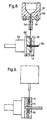
Figure 8 shows a means of winding a fibre optic onto the disk according to an embodiment of the present invention; and -
Figure 9 shows a means of winding a fibre optic onto the disk to produce a seismic sensing device according toFigure 5 . -
Figure 1 shows a fibre optic vibration sensing device or seismic sensing device (10) having a flexural disk (11), that carries a fibre coil (13) and annular Masses (12). The disk (11) is supported on cones (15) and clamped together using a machine screw (16), the entire construction is housed within a can (14) and cones (15). This design gives a high sensitivity to on-axis accelerations, while the symmetrical coils (13,17) and masses (12) mean that the cross-axis sensitivity is reduced. The induced strain in the coil (13) is detected using a high responsivity fibre optic interferometer of the existing types. Coil (17) is used to physically balance the sensing coil (13); this maintains the neutral plane of bending in the centre plane of the flexural disk (11). Coil (17) may be replaced by a different material that acts as a counterweight to sensing coil (13). - The dimensions of the device may vary depending on what is being measured, however, typically the disk (11) is about 2mm thick with a disk radius of 15mm.
Figure 1 is drawn to scale, so that the other dimensions of the device can be seen relative to the disk from this Figure. The fibre length in the coil (13) is typically about 20m, and its thickness is 2mm. The mass may vary in weight but is typically about half a kilogram. -
Figure 2 shows the flexural disk (11) in greater detail. The flexural disk (11) is machined from a solid bar of material, with a suitable modulus of elasticity and density such as aluminium. This disk (11) exhibits a coaxial stub (20) on each face of the disk (11). Also on each face there are four grooves (21) cut into the surface of the disk (11), these extend from the edge of the disk to the outer edge of the fibre coils (13,17). All the features of disk (11) are symmetrical around the plain of the disk and also exhibit rotational symmetry around the axis of the disk (11). - The grooves (21) allow the input and output fibre to pass underneath the mass (12) between and the disk and the mass and exit the seismic sensing device case (14). The disk (11) has a surface finished using suitable device such as a grit blaster to remove any large scale surface anomalies and to provide a good mechanical key to bond to. After the surface is finished it is then primed with a suitable primer, such as 3M's EC1945 two part chromate primer.
- The annular masses (12) are shown in
Figure 3 and are to increase the inertia of the disk of the seismic sensing device and to thereby increase the sensitivity of the device. The masses (12) are formed from a suitable material with sufficient density to dominate the flexural loading of the disk (11). The masses (12) are machined so that they have a small lip (30) this lip (30) contacts the disk (11) along the circumference so as to provide a very low effect on the mode of vibration. Conical taper (31) is cut into the disk; this taper is to match the taper of the conical supports (15). -
Figure 4 shows the conical mounting (15) for the disk (11), it is designed in this manner so that increased stiffness is achievable for low mass. The step (40) is to take the enclosure can (14) -
Figures 5 to 7 show an alternative variation of the vibration sensing device ofFigure 1 . The illustrated device shows twomasses disk 11. The masses have a substantially annular shape and have a diameter that is substantially similar to the diameter of the disk. The masses also each have an outerprotruding lip - To allow the
disk 11 to deform under loading a mounting cone 15 (shown in detail inFigure 7 ) is required as in the previous example; the cone is used to impede any unwanted resonances in the casing interfering with the motion of thedisk 11. In this example the cones have asmall stub axle 15a which passes though a central hole in theannular masses holes hole 11b in the disk. The holes in the disk are sized such that the bolts do not touch the disk and as such do not interfere with the flexion of the disk. In this example there are four bolts (seeFigure 6 ) although any number could be envisaged. The holes are located in a radially inner region, this leaves the radially outer region of the disk free for the mounting of the optical fibre sensing coil. Furthermore, as the mass actually contacts the disk at the edge despite being mounted at the centre you have the advantage of the mass having a large effect while leaving much of the outer circumferential region of the disk free for mounting an opticalfibre sensing coil 13. - Furthermore, as the optical fibre is mounted on the outer portion of the disk the bend radius is relatively large and this reduces optical losses. Generally the minimum bend radius in this example is greater than 6.5mm (as opposed to 2.5mm in the example of
Figure 1 ). Furthermore, mounting the optical fibre in the outer region means that you do not need as many layers of optical fibre for the same length as you would do if it were mounted in an inner region. Fewer layers reduces the height of the optical fibre coil and means that the central plane of the optical fibre sensing coil is closer to the plane of bending of the disk. A thin disk also helps brings these planes close to each other. The amount of motion experienced by the optical fibre increases proportionally to the square of the distance between the plane of bending of the disk (which generally passes though its centre) and the central plane of the sensing coil. However, the stiffness of the disk increases proportionally to the cube of this distance, thus responsivity of the device decreases as this distance increases. For these reasons the optical fibre is mounted directly to the disk with no intermediate material except for a thin layer of adhesive, and a thin disk and a thin coil are preferred. - The optical
fibre sensing coil 13 stops at a certain distance from the outer edge of the disk and a fly lead is left for connection to other optical components. A furtherinert coil 13a is then mounted on the outer region of the disk. Similarly, on the opposite side of the disk aninert coil 17a is mounted outside thecounterbalance coil 17. These coils are arranged such that the circumferential lip of the masses contact the disk at the point these coils are mounted. As these coils are not interrogated any damage to the fibre is unimportant. Theinert coils lip - The shape of the masses (see
figure 6 ) is such that the outer portion has a cross section with a similar slope to the cone on which the mass is mounted. This means that a relatively large mass can be mounted within the device without increasing the size of the device. The mode of operation of the devices of the two examples as follows. Thedevice 10 is mounted with one of thecones 15 in intimate contact with the structure or body under investigation. If the structure moves then this will impart a motion to thecone 15, if the motion of the structure is in the direction of the axis of the cone a force is applied to the disk along its axis. When a force is applied to thedisk 11 the inertia of the masses acting on the edge of the disk causes the disk to deform. The maximum displacement of the disk is towards the edge so the fibre in the coils is localised in the areas of maximum displacement. - When the disk is flexed the deformation is transferred to the fibre coil. This deformation causes the fibre to be stressed along its length. Thus stress will result in a length change that can be detected using fibre optic interferometry techniques.
-
Figure 8 shows the wet winding apparatus used to form the coils (13,17) the fibre (57) passes through a bath (56) of fluid epoxy resin and hardener mixture or other similar bonding material. Epoxy resin is particularly appropriate due to its high rigidity. The fibre (57) then passes through a hypodermic needle (55); this needle is used to position the fibre in the correct position on the disk (11) and to strip the excess resin from the fibre (57). The fibre (57) passes around the stub (20) on the disk (11) and passes on to the winding mandrel (53). Item (54) holds the needle rigidly in position relative to the bath (56) and the positioning arm of the precision winding machine. - The disk (11) is held on to the mandrel (53) by use of threaded bar (50) and an appropriately sized washer and nut. Plates (51) and (52) are polished and coated with a mould release film. This arrangement holds the disk firmly and allows the fibre coils (13,17) to be wound in situ on the flexural disk.
- To fabricate the seismic sensing device (10) first the coils (13,17) have to be wound on to the disk (11) using the wet winding set up as in figure five. The faces of the winding plates (51) and (52) are polished and then covered in a release film as used by the composite manufacturing industry. The fibre (57) is passed through the bath (56) and needle (55) and fixed on to the disk (11), the start of the coil is chosen such that the fibre (57) starts at a groove (21). A wind of fibre (57) is taken around the stub (20) and then fixed to the mandrel (53). The bath is then filled with the appropriate resin system and the coil winding machine is started, when the requisite number of turns has been reached then the machine stops. A length of fibre (57) is drawn through and fixed to the mandrel (53), these lengths of fibre form the connecting leads. At this point the fibre (57) is broken and the ballast coil (17) is wound using a similar method.
- The winding machine has an integral tension controller to prevent too much tension being applied to the fibre (57), which can reduce the device lifetime. The rotational velocity of the mandrel (35) is set at 500 rpm, this allows the tension controller to maintain the correct tension on the fibre and the positioning arm sufficient time to move the fibre to the correct place. Using the needle (55) position system it is not necessary to remove any excess resin as only the correct amount of resin is left on the fibre (57).
- Once the epoxy resin has cured then the device (10) can be assembled from the chosen parts. Care must be taken to not damage the fibre (57) as it exits the disk (11) and the seismic sensing device can (14)
- The Optical Fibre (57) used in an embodiment of this invention has a 6 micron core with an 80 micron cladding. However, other types of optical fibre could be used. The epoxy resin used must have a high modulus to transfer the strains from the disk (11) to the fibre (57).
-
Figure 9 shows a wet winding apparatus similar to that offigure 8 but with a couple of modifications to make it suitable for manufacturing the example of the device illustrated inFigures 5 to 7 . In particular it comprisesspacers fibre coil 13 is wound on to the disk outside of the spacer disk to a diameter of 0.5mm from the edge of the disk. Both the input and output ends of the fibre are made safe to the winding jig and then a furtherinert coil 13a (not shown) is wound onto the sensing coil. As the fibres from the inert coil do not need to be interrogated fly leads from these are not needed. The process is then repeated on the other side of the disk so that coils 17 and 17a (not shown) are formed. The spacers are removed from the disk prior to assembly of the device. - Two
masses 71, 72 (seeFigures 5 and6 ) are then bolted on to the disk such that thelips inert coils holes Figure 5 ). To allow the disk to deform under loading a mountingcone 15 is required. The cone is used to prevent any unwanted resonances in the casing interfering with the motion of the disk. - In operation when the seismic sensing device is accelerated along the axis of the retaining screw (16) the disk (11) is deflected, this deflection is a function of the physical dimensions of the disk (11), the stiffness of the disk (11) and the masses (12). The strains on the upper and lower surfaces of the disk (11) are equal and opposite, due to the positioning of the balancing coil (17) on the opposite side to the sensing coil (13). The strains are transferred to the coils (13,17). This strain causes a change in the optical path length of the coil in the seismic sensing device, which is then detected in the interferometer.
- To prevent rocking modes being set up equal masses (12) are symmetrically applied to the upper and lower surfaces of the disk (11). The can, (14,15) is designed to prevent bending of the central screw (16), the end plates mounting cones (15) serve the dual purposes of creating an end to the package and holding the disk (11) securely. The mountings need to be stiff and as close to the centre of the disk (11) as possible, the cones (15) attach to the disk (11) at the stubs (20) and give the space for the masses (12) to be applied to the disk.
- The optical vibration sensing devices described above are particularly well suited to assembly into an array, individual signals being isolated with the use of time division or wavelength division multiplexing. In particular, the accessibility of both ends of the optical fibre in individual vibration sensing devices aids in this array architecture.
Claims (7)
- A method of manufacturing a vibration sensing device including a coil of optic fibre (57) on a flexural disk (11), flexion of said flexural disk (11) producing a strain in said optic fibre (57) which imposes a variation in at least one predetermined property of an optical signal transmitted through said optical fibre (57), the method being characterized in comprising the steps of(i) passing an optical fibre (57) through a reservoir of resin, such that a layer of resin coats said optical fibre (57), said optical fibre (57) exiting said reservoir of resin via a needle (55), said needle (55) being operable to position said optical fibre (57) above flexural disk (11) and being arranged to allow a suitable amount of resin to coat said optical fiber (57),(ii) winding said resin coated optical fibre (57) onto the flexural disk (11) such that a spiral of optical fibre (57) is attached to said flexural disk (11) by said resin and at least one end of said optical fibre (57) is accessible for connection to external optical components; wherein said optical fibre (57) passes out of said reservoir of resin via the needle (55).
- A method of manufacturing according to claim 1, said method further comprising the step of:mounting said flexural disk (11) centrally and substantially symmetrically about said radial plane, such that a central portion of said first and said second surfaces of said flexural disk (11) are constrained from moving while the circumferential edge of said flexural disk (11) is free to move.
- A method of manufacturing according to claim 1 or claim 2, said method further comprising the step ofmounting a mass upon said flexural disk (11) such that it lies substantially symmetrically about said transverse plane and the loading of the mass is greater towards the circumferential edge of said flexural disk (11) than it is towards the centre.
- A method of manufacturing according to any one of claims 1 to 3, comprising a further step of mounting a counterweight on said second surface of said flexural disk (11) in order to counterbalance said optical fibre (57).
- A method of manufacturing according to claim 4, wherein said counterweight comprises an optical fibre.
- A method of manufacturing according to any one of claims 1 to 5, said method comprising the further step of laying a protective sheathing over said optical fibre (57).
- A method of manufacturing a according to any one of claims 1 to 6, wherein said optical fibre (57) is mounted towards the circumferential edge of said disk.
Applications Claiming Priority (3)
| Application Number | Priority Date | Filing Date | Title |
|---|---|---|---|
| GB0201760 | 2002-01-25 | ||
| GB0201760A GB2384644A (en) | 2002-01-25 | 2002-01-25 | High sensitivity fibre optic vibration sensing device |
| PCT/GB2003/000192 WO2003062772A2 (en) | 2002-01-25 | 2003-01-15 | High sensitivity fibre optic vibration sensing device |
Publications (2)
| Publication Number | Publication Date |
|---|---|
| EP1468258A2 EP1468258A2 (en) | 2004-10-20 |
| EP1468258B1 true EP1468258B1 (en) | 2010-04-14 |
Family
ID=9929766
Family Applications (1)
| Application Number | Title | Priority Date | Filing Date |
|---|---|---|---|
| EP03700906A Expired - Lifetime EP1468258B1 (en) | 2002-01-25 | 2003-01-15 | Method of manufacturing a high sensitivity fibre optic vibration sensing device |
Country Status (6)
| Country | Link |
|---|---|
| US (1) | US7282697B2 (en) |
| EP (1) | EP1468258B1 (en) |
| AT (1) | ATE464543T1 (en) |
| DE (1) | DE60332090D1 (en) |
| GB (1) | GB2384644A (en) |
| WO (1) | WO2003062772A2 (en) |
Cited By (5)
| Publication number | Priority date | Publication date | Assignee | Title |
|---|---|---|---|---|
| US8505625B2 (en) | 2010-06-16 | 2013-08-13 | Halliburton Energy Services, Inc. | Controlling well operations based on monitored parameters of cement health |
| US8584519B2 (en) | 2010-07-19 | 2013-11-19 | Halliburton Energy Services, Inc. | Communication through an enclosure of a line |
| US8930143B2 (en) | 2010-07-14 | 2015-01-06 | Halliburton Energy Services, Inc. | Resolution enhancement for subterranean well distributed optical measurements |
| US9388686B2 (en) | 2010-01-13 | 2016-07-12 | Halliburton Energy Services, Inc. | Maximizing hydrocarbon production while controlling phase behavior or precipitation of reservoir impairing liquids or solids |
| US11808779B2 (en) | 2021-07-07 | 2023-11-07 | Nxp B.V. | Method for identifying an object having a replaceable accessary and an object therefor |
Families Citing this family (21)
| Publication number | Priority date | Publication date | Assignee | Title |
|---|---|---|---|---|
| FR2888339B1 (en) * | 2005-07-07 | 2007-09-21 | Sercel Sa | OPTICAL FIBER SEISMIC SENSOR |
| US20070234789A1 (en) * | 2006-04-05 | 2007-10-11 | Gerard Glasbergen | Fluid distribution determination and optimization with real time temperature measurement |
| US7683312B2 (en) | 2007-10-23 | 2010-03-23 | Us Sensor Systems, Inc. | Fiber-optic interrogator with normalization filters |
| US20110090496A1 (en) * | 2009-10-21 | 2011-04-21 | Halliburton Energy Services, Inc. | Downhole monitoring with distributed optical density, temperature and/or strain sensing |
| WO2011050275A2 (en) | 2009-10-23 | 2011-04-28 | Us Sensor Systems, Inc. | Fiber optic microseismic sensing systems |
| WO2011103032A2 (en) | 2010-02-18 | 2011-08-25 | US Seismic Systems, Inc. | Optical detection systems and methods of using the same |
| US8983287B2 (en) | 2010-02-18 | 2015-03-17 | US Seismic Systems, Inc. | Fiber optic personnel safety systems and methods of using the same |
| US8401354B2 (en) | 2010-02-23 | 2013-03-19 | US Seismic Systems, Inc. | Fiber optic security systems and methods of using the same |
| US8701481B2 (en) | 2010-07-06 | 2014-04-22 | US Seismic Systems, Inc. | Borehole sensing and clamping systems and methods of using the same |
| WO2012103085A2 (en) | 2011-01-25 | 2012-08-02 | US Seismic Systems, Inc. | Light powered communication systems and methods of using the same |
| US9217801B2 (en) | 2011-03-08 | 2015-12-22 | Pacific Western Bank | Fiber optic acoustic sensor arrays and systems, and methods of fabricating the same |
| US8893785B2 (en) | 2012-06-12 | 2014-11-25 | Halliburton Energy Services, Inc. | Location of downhole lines |
| US9441433B2 (en) | 2012-07-27 | 2016-09-13 | Avalon Sciences, Ltd | Remotely actuated clamping devices for borehole seismic sensing systems and methods of operating the same |
| GB201219331D0 (en) * | 2012-10-26 | 2012-12-12 | Optasense Holdings Ltd | Fibre optic cable for acoustic/seismic sensing |
| US9823373B2 (en) | 2012-11-08 | 2017-11-21 | Halliburton Energy Services, Inc. | Acoustic telemetry with distributed acoustic sensing system |
| US20160084731A1 (en) * | 2014-09-22 | 2016-03-24 | The Cleveland Electric Laboratories Company | Acoustic transducer apparatus and method of use |
| CN106672887B (en) * | 2016-12-29 | 2018-05-01 | 武汉理工大学 | A kind of vibration acceleration sensing device based on carborundum fiber F-P resonator |
| US11036008B2 (en) | 2019-02-27 | 2021-06-15 | General Electric Technology Gmbh | Employing depolarizer arrangements to mitigate interference in an optical link due to vibration and current effects |
| FR3099572B1 (en) * | 2019-07-29 | 2021-08-27 | Safran | Measuring device comprising an optical fiber connection and measuring equipment for the instrumentation of an aeronautical apparatus, and an aeronautical apparatus comprising such a measuring device |
| AU2020368425A1 (en) * | 2019-10-17 | 2022-05-26 | Hawk Measurement Systems Pty. Ltd. | A mounting structure for a vibration sensing system |
| CN112629642B (en) * | 2020-12-07 | 2022-07-05 | 中国航空工业集团公司北京长城计量测试技术研究所 | Optical fiber sensing system for vibration test of flow channel in engine |
Family Cites Families (12)
| Publication number | Priority date | Publication date | Assignee | Title |
|---|---|---|---|---|
| FR2541767B1 (en) | 1983-02-25 | 1986-11-21 | Thomson Csf | FIBER OPTIC HYDROPHONE |
| US4959539A (en) * | 1989-03-20 | 1990-09-25 | The United States Of America As Represented By The Secretary Of The Navy | Flexural disk fiber optic hydrophone |
| US5317929A (en) * | 1991-02-07 | 1994-06-07 | Brown David A | Fiber optic flexural disk accelerometer |
| US5903349A (en) * | 1997-04-21 | 1999-05-11 | The United States Of America As Represented By The Secretary Of The Navy | Fiber optic accelerometer sensor and a method of constructing same |
| US6305639B1 (en) * | 1997-11-06 | 2001-10-23 | Pirelli Cavi E Sistemi S.P,A. | Reel and method for supporting optical fibres |
| US6191414B1 (en) * | 1998-06-05 | 2001-02-20 | Cidra Corporation | Composite form as a component for a pressure transducer |
| US6384919B1 (en) * | 1999-10-29 | 2002-05-07 | Northrop Grumman Corporation | Fiber optic seismic sensor |
| US6563967B2 (en) * | 2000-01-27 | 2003-05-13 | Northrop Grumman Corporation | Fiber optic displacement sensor |
| US6496264B1 (en) * | 2000-07-24 | 2002-12-17 | Northrop Grumman Corporation | Fiber optic acoustic sensor with specifically selected flexural disks |
| US6363786B1 (en) * | 2000-07-28 | 2002-04-02 | Litton Systems, Inc. | Dynamically enhanced fiber optic particle motion accelerometer |
| US6473183B1 (en) * | 2001-05-03 | 2002-10-29 | Northrop Grumman Corporation | Shear damped fiber optic sensor |
| US6779402B2 (en) * | 2002-10-18 | 2004-08-24 | Northrop Grumman Corporation | Method and apparatus for measuring acceleration using a fiber optic accelerometer |
-
2002
- 2002-01-25 GB GB0201760A patent/GB2384644A/en not_active Withdrawn
-
2003
- 2003-01-15 DE DE60332090T patent/DE60332090D1/en not_active Expired - Lifetime
- 2003-01-15 WO PCT/GB2003/000192 patent/WO2003062772A2/en active Application Filing
- 2003-01-15 US US10/502,371 patent/US7282697B2/en not_active Expired - Lifetime
- 2003-01-15 AT AT03700906T patent/ATE464543T1/en not_active IP Right Cessation
- 2003-01-15 EP EP03700906A patent/EP1468258B1/en not_active Expired - Lifetime
Cited By (6)
| Publication number | Priority date | Publication date | Assignee | Title |
|---|---|---|---|---|
| US9388686B2 (en) | 2010-01-13 | 2016-07-12 | Halliburton Energy Services, Inc. | Maximizing hydrocarbon production while controlling phase behavior or precipitation of reservoir impairing liquids or solids |
| US8505625B2 (en) | 2010-06-16 | 2013-08-13 | Halliburton Energy Services, Inc. | Controlling well operations based on monitored parameters of cement health |
| US8930143B2 (en) | 2010-07-14 | 2015-01-06 | Halliburton Energy Services, Inc. | Resolution enhancement for subterranean well distributed optical measurements |
| US8584519B2 (en) | 2010-07-19 | 2013-11-19 | Halliburton Energy Services, Inc. | Communication through an enclosure of a line |
| US9003874B2 (en) | 2010-07-19 | 2015-04-14 | Halliburton Energy Services, Inc. | Communication through an enclosure of a line |
| US11808779B2 (en) | 2021-07-07 | 2023-11-07 | Nxp B.V. | Method for identifying an object having a replaceable accessary and an object therefor |
Also Published As
| Publication number | Publication date |
|---|---|
| US7282697B2 (en) | 2007-10-16 |
| GB0201760D0 (en) | 2002-03-13 |
| DE60332090D1 (en) | 2010-05-27 |
| ATE464543T1 (en) | 2010-04-15 |
| EP1468258A2 (en) | 2004-10-20 |
| GB2384644A (en) | 2003-07-30 |
| US20050115320A1 (en) | 2005-06-02 |
| WO2003062772A2 (en) | 2003-07-31 |
| WO2003062772A3 (en) | 2003-12-11 |
Similar Documents
| Publication | Publication Date | Title |
|---|---|---|
| EP1468258B1 (en) | Method of manufacturing a high sensitivity fibre optic vibration sensing device | |
| US5903349A (en) | Fiber optic accelerometer sensor and a method of constructing same | |
| US7345953B2 (en) | Flextensional vibration sensor | |
| CA2387045C (en) | Highly sensitive accelerometer | |
| CA1114639A (en) | Force balancing assembly for transducers | |
| CA1139123A (en) | Moveable element with position sensing means for transducers | |
| US5633960A (en) | Spatially averaging fiber optic accelerometer sensors | |
| JP2863116B2 (en) | Rotation sensor for fiber optic gyroscope | |
| US20090323075A1 (en) | Flexural disc fiber optic sensor | |
| US6384919B1 (en) | Fiber optic seismic sensor | |
| WO2003081186A2 (en) | Vibration sensor having a flextensional body | |
| WO2004038427A1 (en) | Method and apparatus for measuring acceleration using a fiber optic accelerometer | |
| WO2004113839A1 (en) | Polymeric material with voids that compress to allow the polymeric material to absorb applied force and decrease reaction force to one or more sensor fibers | |
| KR100443386B1 (en) | Fiber Optic Seismic Sensor | |
| CN212645880U (en) | Interferometric fiber vector hydrophone with reference interferometer | |
| CN117849394A (en) | Method and device for detecting structural performance of optical fiber acceleration Ji Zengmin | |
| Peters et al. | Application of finite-length displacement sensors to load measurements in a model tail rotor torque tube | |
| Peters et al. | Application of finite-length displacement sensors to precision torque measurements of a tail rotor transmission tube |
Legal Events
| Date | Code | Title | Description |
|---|---|---|---|
| PUAI | Public reference made under article 153(3) epc to a published international application that has entered the european phase |
Free format text: ORIGINAL CODE: 0009012 |
|
| 17P | Request for examination filed |
Effective date: 20040731 |
|
| AK | Designated contracting states |
Kind code of ref document: A2 Designated state(s): AT BE BG CH CY CZ DE DK EE ES FI FR GB GR HU IE IT LI LU MC NL PT SE SI SK TR |
|
| 17Q | First examination report despatched |
Effective date: 20060109 |
|
| RTI1 | Title (correction) |
Free format text: METHOD OF MANUFACTURING A HIGH SENSITIVITY FIBRE OPTIC VIBRATION SENSING DEVICE |
|
| GRAP | Despatch of communication of intention to grant a patent |
Free format text: ORIGINAL CODE: EPIDOSNIGR1 |
|
| GRAS | Grant fee paid |
Free format text: ORIGINAL CODE: EPIDOSNIGR3 |
|
| GRAA | (expected) grant |
Free format text: ORIGINAL CODE: 0009210 |
|
| AK | Designated contracting states |
Kind code of ref document: B1 Designated state(s): AT BE BG CH CY CZ DE DK EE ES FI FR GB GR HU IE IT LI LU MC NL PT SE SI SK TR |
|
| REG | Reference to a national code |
Ref country code: GB Ref legal event code: FG4D |
|
| REG | Reference to a national code |
Ref country code: CH Ref legal event code: EP |
|
| REG | Reference to a national code |
Ref country code: IE Ref legal event code: FG4D |
|
| REF | Corresponds to: |
Ref document number: 60332090 Country of ref document: DE Date of ref document: 20100527 Kind code of ref document: P |
|
| REG | Reference to a national code |
Ref country code: NL Ref legal event code: VDEP Effective date: 20100414 |
|
| PG25 | Lapsed in a contracting state [announced via postgrant information from national office to epo] |
Ref country code: SE Free format text: LAPSE BECAUSE OF FAILURE TO SUBMIT A TRANSLATION OF THE DESCRIPTION OR TO PAY THE FEE WITHIN THE PRESCRIBED TIME-LIMIT Effective date: 20100414 Ref country code: NL Free format text: LAPSE BECAUSE OF FAILURE TO SUBMIT A TRANSLATION OF THE DESCRIPTION OR TO PAY THE FEE WITHIN THE PRESCRIBED TIME-LIMIT Effective date: 20100414 Ref country code: ES Free format text: LAPSE BECAUSE OF FAILURE TO SUBMIT A TRANSLATION OF THE DESCRIPTION OR TO PAY THE FEE WITHIN THE PRESCRIBED TIME-LIMIT Effective date: 20100725 |
|
| PG25 | Lapsed in a contracting state [announced via postgrant information from national office to epo] |
Ref country code: SI Free format text: LAPSE BECAUSE OF FAILURE TO SUBMIT A TRANSLATION OF THE DESCRIPTION OR TO PAY THE FEE WITHIN THE PRESCRIBED TIME-LIMIT Effective date: 20100414 Ref country code: FI Free format text: LAPSE BECAUSE OF FAILURE TO SUBMIT A TRANSLATION OF THE DESCRIPTION OR TO PAY THE FEE WITHIN THE PRESCRIBED TIME-LIMIT Effective date: 20100414 Ref country code: AT Free format text: LAPSE BECAUSE OF FAILURE TO SUBMIT A TRANSLATION OF THE DESCRIPTION OR TO PAY THE FEE WITHIN THE PRESCRIBED TIME-LIMIT Effective date: 20100414 |
|
| PG25 | Lapsed in a contracting state [announced via postgrant information from national office to epo] |
Ref country code: GR Free format text: LAPSE BECAUSE OF FAILURE TO SUBMIT A TRANSLATION OF THE DESCRIPTION OR TO PAY THE FEE WITHIN THE PRESCRIBED TIME-LIMIT Effective date: 20100715 Ref country code: CY Free format text: LAPSE BECAUSE OF FAILURE TO SUBMIT A TRANSLATION OF THE DESCRIPTION OR TO PAY THE FEE WITHIN THE PRESCRIBED TIME-LIMIT Effective date: 20100414 |
|
| PG25 | Lapsed in a contracting state [announced via postgrant information from national office to epo] |
Ref country code: PT Free format text: LAPSE BECAUSE OF FAILURE TO SUBMIT A TRANSLATION OF THE DESCRIPTION OR TO PAY THE FEE WITHIN THE PRESCRIBED TIME-LIMIT Effective date: 20100816 Ref country code: EE Free format text: LAPSE BECAUSE OF FAILURE TO SUBMIT A TRANSLATION OF THE DESCRIPTION OR TO PAY THE FEE WITHIN THE PRESCRIBED TIME-LIMIT Effective date: 20100414 Ref country code: DK Free format text: LAPSE BECAUSE OF FAILURE TO SUBMIT A TRANSLATION OF THE DESCRIPTION OR TO PAY THE FEE WITHIN THE PRESCRIBED TIME-LIMIT Effective date: 20100414 |
|
| PLBE | No opposition filed within time limit |
Free format text: ORIGINAL CODE: 0009261 |
|
| STAA | Information on the status of an ep patent application or granted ep patent |
Free format text: STATUS: NO OPPOSITION FILED WITHIN TIME LIMIT |
|
| PG25 | Lapsed in a contracting state [announced via postgrant information from national office to epo] |
Ref country code: SK Free format text: LAPSE BECAUSE OF FAILURE TO SUBMIT A TRANSLATION OF THE DESCRIPTION OR TO PAY THE FEE WITHIN THE PRESCRIBED TIME-LIMIT Effective date: 20100414 Ref country code: CZ Free format text: LAPSE BECAUSE OF FAILURE TO SUBMIT A TRANSLATION OF THE DESCRIPTION OR TO PAY THE FEE WITHIN THE PRESCRIBED TIME-LIMIT Effective date: 20100414 Ref country code: BE Free format text: LAPSE BECAUSE OF FAILURE TO SUBMIT A TRANSLATION OF THE DESCRIPTION OR TO PAY THE FEE WITHIN THE PRESCRIBED TIME-LIMIT Effective date: 20100414 |
|
| 26N | No opposition filed |
Effective date: 20110117 |
|
| PG25 | Lapsed in a contracting state [announced via postgrant information from national office to epo] |
Ref country code: IT Free format text: LAPSE BECAUSE OF FAILURE TO SUBMIT A TRANSLATION OF THE DESCRIPTION OR TO PAY THE FEE WITHIN THE PRESCRIBED TIME-LIMIT Effective date: 20100414 |
|
| PG25 | Lapsed in a contracting state [announced via postgrant information from national office to epo] |
Ref country code: MC Free format text: LAPSE BECAUSE OF NON-PAYMENT OF DUE FEES Effective date: 20110131 |
|
| REG | Reference to a national code |
Ref country code: CH Ref legal event code: PL |
|
| REG | Reference to a national code |
Ref country code: IE Ref legal event code: MM4A |
|
| PG25 | Lapsed in a contracting state [announced via postgrant information from national office to epo] |
Ref country code: CH Free format text: LAPSE BECAUSE OF NON-PAYMENT OF DUE FEES Effective date: 20110131 Ref country code: LI Free format text: LAPSE BECAUSE OF NON-PAYMENT OF DUE FEES Effective date: 20110131 |
|
| PG25 | Lapsed in a contracting state [announced via postgrant information from national office to epo] |
Ref country code: IE Free format text: LAPSE BECAUSE OF NON-PAYMENT OF DUE FEES Effective date: 20110115 |
|
| PG25 | Lapsed in a contracting state [announced via postgrant information from national office to epo] |
Ref country code: LU Free format text: LAPSE BECAUSE OF NON-PAYMENT OF DUE FEES Effective date: 20110115 |
|
| PG25 | Lapsed in a contracting state [announced via postgrant information from national office to epo] |
Ref country code: TR Free format text: LAPSE BECAUSE OF FAILURE TO SUBMIT A TRANSLATION OF THE DESCRIPTION OR TO PAY THE FEE WITHIN THE PRESCRIBED TIME-LIMIT Effective date: 20100414 Ref country code: BG Free format text: LAPSE BECAUSE OF FAILURE TO SUBMIT A TRANSLATION OF THE DESCRIPTION OR TO PAY THE FEE WITHIN THE PRESCRIBED TIME-LIMIT Effective date: 20100714 |
|
| PG25 | Lapsed in a contracting state [announced via postgrant information from national office to epo] |
Ref country code: HU Free format text: LAPSE BECAUSE OF FAILURE TO SUBMIT A TRANSLATION OF THE DESCRIPTION OR TO PAY THE FEE WITHIN THE PRESCRIBED TIME-LIMIT Effective date: 20100414 |
|
| REG | Reference to a national code |
Ref country code: DE Ref legal event code: R082 Ref document number: 60332090 Country of ref document: DE Representative=s name: BEETZ & PARTNER PATENT- UND RECHTSANWAELTE, DE |
|
| REG | Reference to a national code |
Ref country code: GB Ref legal event code: 732E Free format text: REGISTERED BETWEEN 20140123 AND 20140129 |
|
| REG | Reference to a national code |
Ref country code: DE Ref legal event code: R082 Ref document number: 60332090 Country of ref document: DE Representative=s name: BEETZ & PARTNER MBB PATENT- UND RECHTSANWAELTE, DE Effective date: 20140127 Ref country code: DE Ref legal event code: R082 Ref document number: 60332090 Country of ref document: DE Representative=s name: BEETZ & PARTNER MBB PATENTANWAELTE, DE Effective date: 20140127 Ref country code: DE Ref legal event code: R082 Ref document number: 60332090 Country of ref document: DE Representative=s name: BEETZ & PARTNER MBB, DE Effective date: 20140127 Ref country code: DE Ref legal event code: R082 Ref document number: 60332090 Country of ref document: DE Representative=s name: BEETZ & PARTNER PATENT- UND RECHTSANWAELTE, DE Effective date: 20140127 Ref country code: DE Ref legal event code: R081 Ref document number: 60332090 Country of ref document: DE Owner name: OPTASENSE HOLDINGS LTD., FARNBOROUGH, GB Free format text: FORMER OWNER: QINETIQ LTD., LONDON, GB Effective date: 20140127 Ref country code: DE Ref legal event code: R081 Ref document number: 60332090 Country of ref document: DE Owner name: OPTASENSE HOLDINGS LTD., GB Free format text: FORMER OWNER: QINETIQ LTD., LONDON, GB Effective date: 20140127 |
|
| REG | Reference to a national code |
Ref country code: FR Ref legal event code: TP Owner name: OPTASENSE HOLDINGS LIMITED, GB Effective date: 20140219 |
|
| REG | Reference to a national code |
Ref country code: FR Ref legal event code: PLFP Year of fee payment: 13 |
|
| REG | Reference to a national code |
Ref country code: FR Ref legal event code: PLFP Year of fee payment: 14 |
|
| REG | Reference to a national code |
Ref country code: FR Ref legal event code: PLFP Year of fee payment: 15 |
|
| REG | Reference to a national code |
Ref country code: FR Ref legal event code: PLFP Year of fee payment: 16 |
|
| PGFP | Annual fee paid to national office [announced via postgrant information from national office to epo] |
Ref country code: DE Payment date: 20200123 Year of fee payment: 18 |
|
| PGFP | Annual fee paid to national office [announced via postgrant information from national office to epo] |
Ref country code: FR Payment date: 20200109 Year of fee payment: 18 |
|
| REG | Reference to a national code |
Ref country code: DE Ref legal event code: R119 Ref document number: 60332090 Country of ref document: DE |
|
| PG25 | Lapsed in a contracting state [announced via postgrant information from national office to epo] |
Ref country code: FR Free format text: LAPSE BECAUSE OF NON-PAYMENT OF DUE FEES Effective date: 20210131 |
|
| PG25 | Lapsed in a contracting state [announced via postgrant information from national office to epo] |
Ref country code: DE Free format text: LAPSE BECAUSE OF NON-PAYMENT OF DUE FEES Effective date: 20210803 |
|
| PGFP | Annual fee paid to national office [announced via postgrant information from national office to epo] |
Ref country code: GB Payment date: 20220121 Year of fee payment: 20 |
|
| REG | Reference to a national code |
Ref country code: GB Ref legal event code: PE20 Expiry date: 20230114 |
|
| PG25 | Lapsed in a contracting state [announced via postgrant information from national office to epo] |
Ref country code: GB Free format text: LAPSE BECAUSE OF EXPIRATION OF PROTECTION Effective date: 20230114 |