EP1471688B1 - Kalibrierung eines Endgerätepositionsbestimmungssystems unter Verwendung von Funkfeldstärken - Google Patents
Kalibrierung eines Endgerätepositionsbestimmungssystems unter Verwendung von Funkfeldstärken Download PDFInfo
- Publication number
- EP1471688B1 EP1471688B1 EP04007258.9A EP04007258A EP1471688B1 EP 1471688 B1 EP1471688 B1 EP 1471688B1 EP 04007258 A EP04007258 A EP 04007258A EP 1471688 B1 EP1471688 B1 EP 1471688B1
- Authority
- EP
- European Patent Office
- Prior art keywords
- location
- signal properties
- kernel
- weights
- calibration
- Prior art date
- Legal status (The legal status is an assumption and is not a legal conclusion. Google has not performed a legal analysis and makes no representation as to the accuracy of the status listed.)
- Expired - Lifetime
Links
- 238000005259 measurement Methods 0.000 title description 10
- 230000006870 function Effects 0.000 claims description 58
- 238000000034 method Methods 0.000 claims description 49
- 239000013598 vector Substances 0.000 claims description 35
- 238000012360 testing method Methods 0.000 claims description 11
- 238000012549 training Methods 0.000 claims description 11
- 239000011159 matrix material Substances 0.000 claims description 6
- 238000013507 mapping Methods 0.000 claims description 3
- 238000005070 sampling Methods 0.000 claims 1
- 230000008569 process Effects 0.000 description 17
- 238000004891 communication Methods 0.000 description 11
- 238000010586 diagram Methods 0.000 description 9
- 230000000875 corresponding effect Effects 0.000 description 8
- 238000002474 experimental method Methods 0.000 description 7
- 238000012545 processing Methods 0.000 description 6
- 230000000694 effects Effects 0.000 description 5
- 230000003287 optical effect Effects 0.000 description 4
- 235000014510 cooky Nutrition 0.000 description 3
- 238000009472 formulation Methods 0.000 description 3
- 230000005055 memory storage Effects 0.000 description 3
- 239000000203 mixture Substances 0.000 description 3
- 230000006855 networking Effects 0.000 description 3
- 238000004088 simulation Methods 0.000 description 3
- 238000013179 statistical model Methods 0.000 description 3
- 230000009471 action Effects 0.000 description 2
- 230000004888 barrier function Effects 0.000 description 2
- 230000002093 peripheral effect Effects 0.000 description 2
- 238000012935 Averaging Methods 0.000 description 1
- 230000004075 alteration Effects 0.000 description 1
- 238000013459 approach Methods 0.000 description 1
- 230000008901 benefit Effects 0.000 description 1
- 230000015556 catabolic process Effects 0.000 description 1
- 238000010276 construction Methods 0.000 description 1
- 230000002596 correlated effect Effects 0.000 description 1
- 230000007423 decrease Effects 0.000 description 1
- 238000006731 degradation reaction Methods 0.000 description 1
- 230000001419 dependent effect Effects 0.000 description 1
- 238000001514 detection method Methods 0.000 description 1
- 230000003467 diminishing effect Effects 0.000 description 1
- 230000009977 dual effect Effects 0.000 description 1
- 238000005516 engineering process Methods 0.000 description 1
- 238000009434 installation Methods 0.000 description 1
- 238000003064 k means clustering Methods 0.000 description 1
- 238000010801 machine learning Methods 0.000 description 1
- 238000012423 maintenance Methods 0.000 description 1
- 238000000691 measurement method Methods 0.000 description 1
- 238000012986 modification Methods 0.000 description 1
- 230000004048 modification Effects 0.000 description 1
- 239000013307 optical fiber Substances 0.000 description 1
- 238000012805 post-processing Methods 0.000 description 1
- 230000009467 reduction Effects 0.000 description 1
- 238000011160 research Methods 0.000 description 1
- 230000004044 response Effects 0.000 description 1
- 238000001228 spectrum Methods 0.000 description 1
- 230000002123 temporal effect Effects 0.000 description 1
- 238000012546 transfer Methods 0.000 description 1
- 230000009466 transformation Effects 0.000 description 1
- 238000000844 transformation Methods 0.000 description 1
- 230000007704 transition Effects 0.000 description 1
Images


Classifications
-
- G—PHYSICS
- G01—MEASURING; TESTING
- G01S—RADIO DIRECTION-FINDING; RADIO NAVIGATION; DETERMINING DISTANCE OR VELOCITY BY USE OF RADIO WAVES; LOCATING OR PRESENCE-DETECTING BY USE OF THE REFLECTION OR RERADIATION OF RADIO WAVES; ANALOGOUS ARRANGEMENTS USING OTHER WAVES
- G01S5/00—Position-fixing by co-ordinating two or more direction or position line determinations; Position-fixing by co-ordinating two or more distance determinations
- G01S5/02—Position-fixing by co-ordinating two or more direction or position line determinations; Position-fixing by co-ordinating two or more distance determinations using radio waves
- G01S5/0205—Details
- G01S5/021—Calibration, monitoring or correction
-
- G—PHYSICS
- G01—MEASURING; TESTING
- G01C—MEASURING DISTANCES, LEVELS OR BEARINGS; SURVEYING; NAVIGATION; GYROSCOPIC INSTRUMENTS; PHOTOGRAMMETRY OR VIDEOGRAMMETRY
- G01C21/00—Navigation; Navigational instruments not provided for in groups G01C1/00 - G01C19/00
- G01C21/20—Instruments for performing navigational calculations
- G01C21/206—Instruments for performing navigational calculations specially adapted for indoor navigation
-
- G—PHYSICS
- G01—MEASURING; TESTING
- G01S—RADIO DIRECTION-FINDING; RADIO NAVIGATION; DETERMINING DISTANCE OR VELOCITY BY USE OF RADIO WAVES; LOCATING OR PRESENCE-DETECTING BY USE OF THE REFLECTION OR RERADIATION OF RADIO WAVES; ANALOGOUS ARRANGEMENTS USING OTHER WAVES
- G01S5/00—Position-fixing by co-ordinating two or more direction or position line determinations; Position-fixing by co-ordinating two or more distance determinations
- G01S5/02—Position-fixing by co-ordinating two or more direction or position line determinations; Position-fixing by co-ordinating two or more distance determinations using radio waves
- G01S5/0252—Radio frequency fingerprinting
- G01S5/02528—Simulating radio frequency fingerprints
-
- H—ELECTRICITY
- H04—ELECTRIC COMMUNICATION TECHNIQUE
- H04W—WIRELESS COMMUNICATION NETWORKS
- H04W64/00—Locating users or terminals or network equipment for network management purposes, e.g. mobility management
-
- H—ELECTRICITY
- H04—ELECTRIC COMMUNICATION TECHNIQUE
- H04W—WIRELESS COMMUNICATION NETWORKS
- H04W16/00—Network planning, e.g. coverage or traffic planning tools; Network deployment, e.g. resource partitioning or cells structures
- H04W16/18—Network planning tools
- H04W16/20—Network planning tools for indoor coverage or short range network deployment
-
- H—ELECTRICITY
- H04—ELECTRIC COMMUNICATION TECHNIQUE
- H04W—WIRELESS COMMUNICATION NETWORKS
- H04W16/00—Network planning, e.g. coverage or traffic planning tools; Network deployment, e.g. resource partitioning or cells structures
- H04W16/22—Traffic simulation tools or models
- H04W16/225—Traffic simulation tools or models for indoor or short range network
-
- H—ELECTRICITY
- H04—ELECTRIC COMMUNICATION TECHNIQUE
- H04W—WIRELESS COMMUNICATION NETWORKS
- H04W88/00—Devices specially adapted for wireless communication networks, e.g. terminals, base stations or access point devices
- H04W88/18—Service support devices; Network management devices
Definitions
- This invention is related to IEEE 802.11 devices, and more specifically, to locating wireless devices using wireless signal strengths.
- an 802.11 wireless client as a location sensor (e.g. , a portable computer as a receiver) is becoming increasingly popular way of enabling location-based services. Triangulation of signal strengths from multiple access points (APs) may be used to pinpoint location of the receiving device down to a few meters. However, this level of accuracy comes at a price of requiring tedious and time-consuming manual labor in order to obtain spatially high-density calibration data of signal strengths as a function of location.
- APs access points
- One alternative to manual calibration is to analytically predict signal strengths based on a floor plan of a building, physical simulation of radio frequency (RF) propagation, and knowledge of the locations of wireless access points. It was discovered, for the chosen simulation method, that physically simulating signal strengths increased median location error by approximately 46% (from 2.94 meters to 4.3 meters) over values obtained by manual calibration. Moreover, a good physical simulation usually requires a more detailed model of the building than is normally available.
- RF radio frequency
- RADAR In the realm of IEEE 802.11 locations, one published work was based on the RADAR system, an in-building RF-based location and tracking system. RADAR worked based on a table of indoor locations and corresponding signal strengths. Using a manually calibrated table, the nearest neighbor algorithm gave a median spatial error of approximately 2.94 meters. Another table based on simulated radio wave propagation allowed the avoidance of most of the calibration work at the cost of increasing the median error to 4.3 meters. The RADAR work also looked at the problem of reducing calibration effort. It was found that reducing the number of calibration points from seventy to forty had only a small negative impact on accuracy. In follow-on work, RADAR was enhanced to use a Viterbi-like algorithm on short paths through the building. This further reduced the median error to approximately 2.37 meters.
- Another location service used signal-to-noise ratios, instead of the more commonly used raw signal strengths.
- the location algorithm was a Bayesian network, manually trained at discrete locations in two buildings.
- the Bayes formulation allowed the inclusion of a priori probabilities of a person's location, as well as transition probabilities between locations. In one test on twelve locations in a hallway, the service was capable of identifying the highest probability to the correct location 97% of the time, not counting the 15% of the time it was inconclusive.
- IEEE 802.11 was used to compute the location of wireless PocketPCs, both indoors and outdoors. Instead of manual calibration, a formula was used that approximated the distance to a wireless access point as a function of signal strength. Using a hill-climbing algorithm, the system computes location down to about ten meters (approximately thirty-five feet) using signal strengths from multiple access points.
- WO 02/054813 A1 relates to location estimation in wireless telecommunication networks.
- the telecommunication network comprises a plurality of channels for simultaneous communication, each channel has at least one signal parameter that varies with location differently from the other channels.
- a set of calibration data is determined, each set of calibration data comprises the location of the respective calibration point and at least one measured signal parameter, a statistical model of the signal parameters of the several channels is maintained versus a receiver's location, at least one signal parameter is measured at the receiver and the location of the received is estimated based on the statistical model and measured signal parameters.
- the statistical model can be differently implemented such as by regression trees.
- the signal parameter varying with location comprises signal strength, timing advance and error ratio.
- the present invention disclosed and claimed herein in one aspect thereof, comprises an IEEE 802.11 location-based technique for coarsely calibrating a system used to determine a precise triangulated location in view of radio signal strengths at a given location.
- the calibration technique is based upon a regression function that produces adequately accurate location information as a function of signal strength regardless of gaps in the calibration data or minimally available data.
- the architecture of the present invention discloses a new IEEE 802.11 location system based upon a relatively easy calibration procedure of recording signal strengths down to room resolution (e.g. , from an arbitrary point or set of points in each room of the building or from a more precise location within each room).
- the disclosed location algorithm is designed to work in spite of missing calibration data, that is, data that is unobtainable because a room, set of rooms, or even a building wing, may be inaccessible.
- the regression algorithm takes a set of signal strengths from known locations in a building and generates a function that maps signal strength to (x, y ) location. This function may then be used to estimate new location(s).
- Radial basis functions which are simple to express and compute, are used for regression.
- One embodiment provides a more precise location measurement methodology, where calibration is accomplished by placing the receiver at one point at the location to be measured, and measuring signal properties based upon that single receiver location. The user selects the approximate location of the receiver on a map that shows the position of the receiver relative to the location to be measured. Additionally, an averaging function is provided that averages the last ten computed (x,y) locations to further reduce noise.
- the user moves the receiver around at the location, e.g. , in the room, while taking measurements at several calibration points.
- the exact location of the receiver is not known.
- the location of the receiver is taken as the (x,y) centroid of the room, no matter where in the room the receiver was located when the measurements were made.
- a component may be, but is not limited to being, a process running on a processor, a processor, an object, an executable, a thread of execution, a program, and/or a computer.
- a component may be, but is not limited to being, a process running on a processor, a processor, an object, an executable, a thread of execution, a program, and/or a computer.
- an application running on a server and the server can be a component.
- One or more components may reside within a process and/or thread of execution and a component may be localized on one computer and/or distributed between two or more computers.
- the term "inference” refers generally to the process of reasoning about or inferring states of the system, environment, and/or user from a set of observations as captured via events and/or data. Inference can be employed to identify a specific context or action, or can generate a probability distribution over states, for example. The inference can be probabilistic-that is, the computation of a probability distribution over states of interest based on a consideration of data and events. Inference can also refer to techniques employed for composing higher-level events from a set of events and/or data. Such inference results in the construction of new events or actions from a set of observed events and/or stored event data, whether or not the events are correlated in close temporal proximity, and whether the events and data come from one or several event and data sources.
- the disclosed calibration architecture supports the premise that calibration efforts can be significantly reduced with only a minor reduction in spatial accuracy. This effectively diminishes one of the most daunting practical barriers to wider adoption of an IEEE 802.11 location-based measurement technique.
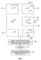
- FIG. 1 there is illustrated geometry of the calibration procedure for a system of the present invention that determines new location(s) based on signal characteristics. These new location(s) are expected to be within a region 100.
- Region 100 may be a building, a floor of a building, or any other region that has coverage by one or more transmitters 110.
- the transmitters 110 may be located internal and external to the region 100.
- These transmitters 110 may be, but are not required to be, for example, access point (AP) transceivers disposed on a network.
- AP access point
- the phrase "transmitting device” and the term “transmitter(s)” should be understood to include any device that may or may not be disposed on a network and that transmits a signal.
- Region 100 is divided into sections 120, which sections 120 may include, for example, rooms, hallways, or lounges in a building, and thus may be of variable size. Alternatively, the sections 120 may be particular locations within rooms. The transmitters 110 are not necessarily located in the sections 120. Furthermore, there can be additional areas of region 100 that are not divided into sections 120.
- the sections 120 may contain one or more calibration points 130.
- a receiver 140 is placed sequentially at every calibration point 130.
- one or more signal characteristics of every receivable transmitter 110 are recorded.
- the transmitters 110 are transceivers that are compliant with an IEEE 802.11 standard and the signal characteristics are the signal strengths of the transmitters 110, measured at the calibration point 130.
- the identity of the corresponding section 120 is recorded. The identity of the corresponding section 120 can be indicated, for example, by a user selecting a section from a map.
- the spatial location of all sections 120 are also required for calibration. These spatial locations can be the centroid of the spatial extent of each section 120.
- the calibration point 130 is located at a known location inside each section 120.
- the signal characteristics are then measured multiple times, while the receiver 140 is rotated in place at the single calibration point 130.
- the spatial location of section 120 is taken to be the spatial location of the calibration point 130.
- the signal characteristics are measured by receiver 140 at all calibration points 130 and the spatial locations from all sections 120 are gathered, at act 150. Regression is then performed upon this data, at act 160. Regression operates on the gathered data to produce a regression function, as indicated at an act 170, which can be used subsequently to estimate new location(s) throughout the region 100 based on newly measured signal characteristics.
- These new location(s) are not constrained to lie on the calibration points 130. Indeed, they are not even constrained to lie within sections 120; they can occur at locations that are inaccessible at the time of calibration.
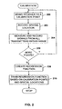
- FIG. 2 there is illustrated a flow diagram of a general calibration process in accordance with the present invention. While, for purposes of simplicity of explanation, the methodology of FIG. 2 , and any subsequent methodologies in, e.g., the form of flow charts, are shown and described herein as a series of acts, it is to be understood and appreciated that the present invention is not limited by the order of acts, as some acts may, in accordance with the present invention, occur in different orders and/or concurrently with other acts from that shown and described herein. For example, those skilled in the art will understand and appreciate that a methodology could alternatively be represented as a series of interrelated states or events, such as in a state diagram. Moreover, not all illustrated acts may be required to implement a methodology in accordance with the present invention.
- the receiver is brought to a calibration point 130.
- the spatial location of the receiver is then recorded. Note that recording of the spatial location information need not be performed at each calibration point, but may be recorded only once during calibration of a section 120.
- the receiver measures and records signal strengths of one or more transmitters of the location, as indicated at 204.
- flow returns to 200 to bring the receiver to that next calibration point 130, and continue the measurement and recording process for that calibration point 130. If no other calibration point 130 must be measured, flow proceeds from 206 to 208, to create a regression function.
- This regression function is trained via regression.
- the training set comprises the signal strengths measured at calibration points 130 and the spatial locations of sections 120.
- the regression function is then determined that provides position in (x,y) coordinates as a function of signal strengths over the entire region 100. Alternatively, the regression function may provide (x,y,z) coordinates, if the region 100 extends over multiple floors of a building.
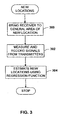
- FIG. 3 there is illustrated a flow diagram of a process for determining new location(s).
- a receiver is brought to a general area of the new location. This location may be one that was previously visited or a location that is being visited for the first time. Signal strengths are then measured and recorded, as indicated at 302. The signals may be received from any transmitters associated with region 100.
- the regression function is employed to estimate new location(s) within region 100, based on the signal strengths measured by the receiver at 302. The process then reaches a Stop block.
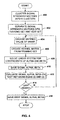
- FIG. 4 there is illustrated a more detailed flow diagram of the process for determining mapping from signal strengths to (x,y) location in accordance with the present invention.
- signal strength vectors from every section 120 are clustered into K clusters.
- all signal strength vectors are separated into a training set and a test set of vectors.
- an untried value of sigma ( ⁇ ) is chosen.
- ⁇ an untried value of sigma
- ⁇ is chosen.
- a kernel matrix is created from the training set.
- the linear system is solved for coefficients of alpha ( ⁇ ) and beta ( ⁇ ).
- the values of sigma ( ⁇ ), alpha ( ⁇ ), and beta ( ⁇ ) are saved.
- sigma ( ⁇ ), alpha ( ⁇ ), and beta ( ⁇ ) are evaluated on the test set utilizing Equations (2) and (3).
- each set of calibration signal strength readings is designated with a vector s i , where i indexes over substantially all calibration vectors in substantially all the room locations.
- Each calibration vector has a corresponding (x i , y i ) giving the location from which it was taken. This may be the centroid of the spatial extent of section 120 or wherever the receiver is placed.
- Each signal strength vector s i has a plurality of elements, one element for each transmitter receivable in region 100. The elements in s i corresponding to transmitters that were not sensed at the calibration point 130 were given a value of one less than the minimum signal strength seen for the whole experiment.
- the present invention uses regression to form the regression function that maps signal strength vector(s) into locations.
- the present invention can map a signal strength vector into a new location that has never been calibrated. If classification (rather than regression) is still desired, a post-processing check can be made to determine which room, if any, contains the estimated location.
- Regression fits a function to the calibration vectors s i and the corresponding room coordinates (x i ,y i ).
- K ( r ) is a chosen kernel function
- S * j are the chosen kernel function centers
- ⁇ j and ⁇ j are the computed weights based on calibration data.
- the Euclidean distance r between an observed signal strength vector s and a stored signal strength vector s * j is shown by ⁇ s - s * j ⁇ .
- This choice of kernel function also requires a choice of scale parameter sigma ( ⁇ ), which is described below. Additionally, the choice of the M kernel centers s * j is also described below.
- the present invention uses a least-squares fit to compute the weights ⁇ j and ⁇ j based on the calibration data.
- K T a K T ⁇ x
- K is an N x M matrix of K ij
- x ( x 0 - C x ,x 1 - C x , - - -,x N-2 - c x ,x N-1 - c x ) T
- K T K has size M x M, where M is a chosen number of stored signal strength vectors.
- K T K is a kernel matrix.
- Solving Equation (5) with M larger than 27,000 (as is used in the embodiment of FIG. 1 ) would be extremely computationally intensive.
- Equation (4) may be weighted by the inverse of the variance of the uncertainty for its corresponding calibration point. In the art, this is known as heteroscedastic regression.
- an optional step is to average together the results of the last several locations to reduce noise.
- the last ten (x,y) results were averaged together.
- a second set of test vectors were taken a few days separated from the training data.
- the second set numbered 25,457 readings to serve as test data.
- the kernel regression method yielded an rms error of approximately 3.75 meters. Computation of the rms error is known in the art, and thus not shown here.
- the location algorithm of the present invention works based on regression of signal strength training data taken from known room locations.
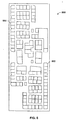
- FIG. 5 there is illustrated a layout of a typical office floor 500 of rooms 502 utilized for a sample application of the calibration process of the present invention.
- the floor 500 includes 132 rooms 502 of which 118 were accessible.
- the area of the floor 500 is approximately 2,680 square meters.
- the floor was taken to be region 100.
- the building maps of the floors were extracted both as polygon representations and bitmaps. The coordinates of all maps were expressed in actual floor coordinates in meters.
- the algorithm was evaluated on the one floor 500 with the 118 different rooms.
- each accessible section was entered with a wirelessly connected receiver, e.g. , the portable PC, running the logging program.
- the logging program used the WRAPI interface to obtain signal strengths from all the visible IEEE 802.11 transmitters.
- the receiver measured signals for approximately sixty seconds in each location.
- the receiver was oriented in a number of different ways to factor out orientation effects.
- a scan rate of 3.4 Hz was used providing approximately 200 scans for each location.
- Each scan yielded the set of signal strengths and the MAC (Media Access Controller) addresses of the wireless access points.
- the wireless communication interface could "see" 3.9 AP's at any given time.
- a running average filter was applied to the computed location vectors.
- the filter was ten samples long, which induced a delay of approximately 2.9 seconds at the scan rate of 3.4 Hz.
- the first s seconds of calibration data were processed with the same training algorithm, and then tested with the entire test set. Accuracy does not suffer significantly even when the time spent in each location is only ten seconds. At ten seconds, the rms error had only increased by approximately 12% (or 0.45 meters) from the rms error at sixty seconds. At a data rate of 3.4 Hz, ten seconds of data yielded only thirty-four signal strength vectors. This indicates that it is not necessary to spend much time at each location during calibration.
- the effect of reducing the number of calibration locations from the original full set of 137 locations down to 10% of the original was tested.
- a k-means clustering algorithm was run on the original locations to make k clusters.
- the k original locations nearest the k cluster centroids were chosen as those for calibration.
- the rms error grows as the number of locations decreases. However, even at 50%, the rms error has only grown by 20% (0.74 meters), and at 20%, has grown by 42% ( 1.59 meters). At 10% of the original locations, the rms error is 9.19 meters, which is an increase of 145% (5.44 meters) over the best result at 100%.
- both the time spent at each location and the number of locations can be significantly reduced with only a minor degradation in accuracy. For example, spending thirty seconds in 40% of the locations increases the rms error by only approximately 21 % (from 3.75 meters to 4.55 meters), yet reduces the calibration effort by much more than half.
- GUI 600 for facilitating signal strength logging of the calibration data.
- the GUI 600 facilitates the display of a floor graphical representation 602 of the floor 500, and rooms thereof.
- the user indicates the location of the receiver by selecting a room from the floor representation 602 via a mouse, keyboard, or other conventional input device.
- a signal strength subwindow 604 for presenting a signal strength indicator plot 605 that displays a representation of the measured signal strengths from nearby transmitters.
- a first bar 606 includes a first color or fill pattern that indicates the signal was received from a transmitter on the current floor being calibrated.
- data 608 that indicates the signal strength data, the floor on which the room is located, and the room number of the transmitter (i.e., 113/3/3327).
- the transmitter was in building number (113), room number 3327 (also denoted graphically at 610) of the third floor (3).
- a second bar identification 612 may be used to indicate measurements received from transmitters on floors other than the current floor being calibrated.
- the bar 612 is associated with room 113/4/4327, which is a room 4327 on the fourth floor of building 113.
- the GUI can be programmed to provide a wide variety of graphical responses to measure signals, including flashing bars, and text, audio output signals, etc., commonly available for providing such interface features.
- the interface 600 also includes a Location Input subwindow 614 that allows the user to zoom in on a floor map via a Map Zoom subwindow, and choose a floor for calibration via a Floor Chooser subwindow.
- the interface 600 further includes a Scan Control subwindow 616 for selecting the scan rate (in Hertz) for signal detection.
- the user can also direct logging of the data to a location on the receiving device via a Logging path field 618.
- the user may also select a remote network storage location by entering the corresponding network path in the path filed 618. Once entered, all data is automatically stored in the designated file location.
- One barrier to deploying an IEEE 802.11-based location system is the calibration effort. In the disclosed example, approximately four hours were spent calibrating 118 rooms on one floor of the building. It is desirable to know if this amount of calibration is really necessary. In particular, it is desirable to evaluate the effect of reducing the time spent in each room and reducing the number of rooms visited. By training on subsets of the original training data, the effects of reducing the time and number of rooms was simulated.
- the disclosed invention is equally applicable to determining the location of a transmitter by fixing a number of receivers at known locations and measuring the strength of a single transmitter at various calibration locations. The latter would be applicable to the case where the transmitter is a source of audio (e.g. , a human), while the receiver is a set of audio microphones.
- the transmitter is a source of audio (e.g. , a human)
- the receiver is a set of audio microphones.
- calibration and regression need not operate on signal strength.
- Various signal properties can be used, such as phase, autocorrelation, or spectrum. Regression can apply equally well to these alternative signal properties, even if each property itself is not a scalar.
- the input to a kernel regression system would then consist of a vector that comprises multiple vectors of signal properties, appended together.
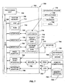
- FIG. 7 there is illustrated a block diagram of a computer operable to execute the disclosed architecture.
- FIG. 7 and the following discussion are intended to provide a brief, general description of a suitable computing environment 700 in which the various aspects of the present invention may be implemented. While the invention has been described above in the general context of computer-executable instructions that may run on one or more computers, those skilled in the art will recognize that the invention also may be implemented in combination with other program modules and/or as a combination of hardware and software.
- program modules include routines, programs, components, data structures, etc., that perform particular tasks or implement particular abstract data types.
- inventive methods may be practiced with other computer system configurations, including single-processor or multiprocessor computer systems, minicomputers, mainframe computers, as well as personal computers, hand-held computing devices, microprocessor-based or programmable consumer electronics, and the like, each of which may be operatively coupled to one or more associated devices.
- inventive methods may also be practiced in distributed computing environments where certain tasks are performed by remote processing devices that are linked through a communications network.
- program modules may be located in both local and remote memory storage devices.
- an exemplary environment 700 for implementing various aspects of the invention includes a computer 702, the computer 702 including a processing unit 704, a system memory 706 and a system bus 708.
- the system bus 708 couples system components including, but not limited to the system memory 706 to the processing unit 704.
- the processing unit 704 may be any of various commercially available processors. Dual microprocessors and other multi-processor architectures also can be employed as the processing unit 704.
- the system bus 708 can be any of several types of bus structure including a memory bus or memory controller, a peripheral bus and a local bus using any of a variety of commercially available bus architectures.
- the system memory 706 includes read only memory (ROM) 710 and random access memory (RAM) 712.
- ROM read only memory
- RAM random access memory
- BIOS basic input/output system
- BIOS basic routines that help to transfer information between elements within the computer 702, such as during start-up, is stored in the ROM 710.
- the computer 702 further includes a hard disk drive 714, a magnetic disk drive 716, (e.g. , to read from or write to a removable disk 718) and an optical disk drive 720, ( e.g. , reading a CD-ROM disk 722 or to read from or write to other optical media).
- the hard disk drive 714, magnetic disk drive 716 and optical disk drive 720 can be connected to the system bus 708 by a hard disk drive interface 724, a magnetic disk drive interface 726 and an optical drive interface 728, respectively.
- the drives and their associated computer-readable media provide nonvolatile storage of data, data structures, computer-executable instructions, and so forth.
- the drives and media accommodate the storage of broadcast programming in a suitable digital format.
- computer-readable media refers to a hard disk, a removable magnetic disk and a CD
- other types of media which are readable by a computer such as zip drives, magnetic cassettes, flash memory cards, digital video disks, cartridges, and the like, may also be used in the exemplary operating environment, and further that any such media may contain computer-executable instructions for performing the methods of the present invention.
- a number of program modules can be stored in the drives and RAM 712, including an operating system 730, one or more application programs 732, other program modules 734 and program data 736. It is appreciated that the present invention can be implemented with various commercially available operating systems or combinations of operating systems.
- a user can enter commands and information into the computer 702 through a keyboard 738 and a pointing device, such as a mouse 740.
- Other input devices may include a microphone, an IR remote control, a joystick, a game pad, a satellite dish, a scanner, or the like.
- These and other input devices are often connected to the processing unit 704 through a serial port interface 742 that is coupled to the system bus 708, but may be connected by other interfaces, such as a parallel port, a game port, a universal serial bus (“USB”), an IR interface, etc.
- a monitor 744 or other type of display device is also connected to the system bus 708 via an interface, such as a video adapter 746.
- a computer typically includes other peripheral output devices (not shown), such as speakers, printers etc.
- the computer 702 may operate in a networked environment using logical connections to one or more remote computers, such as a remote computer(s) 748.
- the remote computer(s) 748 may be a workstation, a server computer, a router, a personal computer, portable computer, microprocessor-based entertainment appliance, a peer device or other common network node, and typically includes many or all of the elements described relative to the computer 702, although, for purposes of brevity, only a memory storage device 750 is illustrated.
- the logical connections depicted include a local area network (LAN) 752 and a wide area network (WAN) 754.
- LAN local area network
- WAN wide area network
- the computer 702 When used in a LAN networking environment, the computer 702 is connected to the local area network 752 through a network interface or adapter 756.
- the adaptor 756 may facilitate wired or wireless communication to the LAN 752, which may also include a wireless access point disposed thereon for communicating with the wireless adaptor 756.
- the computer 702 When used in a WAN networking environment, the computer 702 typically includes a modem 758, or is connected to a communications server on the LAN, or has other means for establishing communications over the WAN 754, such as the Internet.
- the modem 758 which may be internal or external, is connected to the system bus 708 via the serial port interface 742.
- program modules depicted relative to the computer 702, or portions thereof, may be stored in the remote memory storage device 750. It will be appreciated that the network connections shown are exemplary and other means of establishing a communications link between the computers may be used.
- the system 800 includes one or more client(s) 802.
- the client(s) 802 can be hardware and/or software (e.g. , threads, processes, computing devices).
- the client(s) 802 can house cookie(s) and/or associated contextual information by employing the present invention, for example.
- the system 800 also includes one or more server(s) 804.
- the server(s) 804 can also be hardware and/or software (e.g. , threads, processes, computing devices).
- the servers 804 can house threads to perform transformations by employing the present invention, for example.
- One possible communication between a client 802 and a server 804 may be in the form of a data packet adapted to be transmitted between two or more computer processes.
- the data packet may include a cookie and/or associated contextual information, for example.
- the system 800 includes a communication framework 806 that can be employed to facilitate communications between the client(s) 802 and the server(s) 804. Communications may be facilitated via a wired (including optical fiber) and/or wireless technology.
- the client(s) 802 are operably connected to one or more client data store(s) 808 that can be employed to store information local to the client(s) 802 ( e.g. , cookie(s) and/or associated contextual information).
- the server(s) 804 are operably connected to one or more server data store(s) 810 that can be employed to store information local to the servers 804.
Claims (32)
- Verfahren zur Kalibrierung eines Systems, das zum Bestimmen eines neuen Standorts (neuer Standorte) von drahtlosen Geräten in Abhängigkeit von beobachteten Signaleigenschaften verwendet wird, umfassend:Messen (150) von Signaleigenschaften, die zu identifizierten Standorten gehören; undErzeugen (160) einer Kernel-Regressionsfunktion, basierend zumindest zum Teil auf den Signaleigenschaften, wobei die Funktion einen neuen Standort (neue Standorte) als eine Funktion von beobachteten Signaleigenschaften ungeachtet von Lücken in den Kalibrierungsdaten schätzt, die Regressionsfunktion eine Vielzahl von Kerneifunktionen umfasst, jede Kernelfunktion die Differenz zwischen einem Vektor von beobachteten Signaleigenschaften und einem Vektor von gespeicherten Signaleigenschaften berechnet, der Vektor von gespeicherten Signaleigenschaften durch Bündeln (400) einer Vielzahl von Vektoren von gemessenen Signaleigenschaften und Einsetzen eines Bündelzentrums als ein Kernelzentrum berechnet wird.
- Verfahren nach Anspruch 1, wobei die Kernelfunktionen isotrope Gauß'sche Kernelfunktionen sind.
- Verfahren nach Anspruch 1, wobei die Regressionsfunktion des Weiteren Gewichte und einen Skalierungsparameter umfasst, so dass jede Kernelfunktion von dem Skalierungsparameter abhängt, wobei der Skalierungsparameter des Weiteren bestimmt wird durch
Auswählen einer Vielzahl der Skalierungsparameterwerte;
für jeden Skalierungsparameterwert: Anpassen der Gewichte auf einen ersten Teilsatz der Signaleigenschaften unter Verwendung des Skalierungsparameterwertes;
Evaluieren der Regressionsfunktion unter Verwendung der auf einen zweiten Teilsatz der Signaleigenschaften angepassten Gewichte, wobei der zweite Teilsatz disjunkt von dem ersten Teilsatz ist;
Auswählen eines besten Skalierungsparameters, wobei die Regressionsfunktion den geringsten Standortfehler an dem zweiten Teilsatz von Signaleigenschaften ermittelt; und
Speichern des besten Skalierungsparameters und der entsprechenden Gewichte. - Verfahren nach Anspruch 1, wobei die Regressionsfunktion Gewichte umfasst und die Aktion zum Erzeugen der Regressionsfunktion das Anpassen der Regressionsfunktion an die gemessenen Signaleigenschaften durch Anpassen der Gewichte umfasst.
- Verfahren nach Anspruch 4, wobei die Gewichte gemäß einem Anpassungsverfahren der kleinsten Quadrate angepasst werden.
- Verfahren nach Anspruch 4, wobei die Gewichte durch Berechnen einer Kernelmatrix angepasst werden.
- Verfahren nach Anspruch 4, wobei die Gewichte basierend auf einer Schätzung der zu den einzelnen identifizierten Standorten gehörenden Standortunsicherheit angepasst werden.
- Verfahren nach Anspruch 4, wobei die Gewichte eine Vielzahl von Gewichten zum Berechnen eines Standorts x und eine Vielzahl von Gewichten zum Berechnen eines Standorts y umfassen.
- Verfahren nach Anspruch 1, wobei die Regressionsfunktion des Weiteren zusätzliche Parameter umfasst, die aus einem Zentroid der identifizierten Standorte berechnet werden.
- Verfahren nach Anspruch 1, wobei die Signaleigenschaften von drahtlosen Funksignalen stammen, die von drahtlosen Sendeempfängern übertragen werden, und die Signaleigenschaften Signalstärken umfassen.
- Verfahren nach Anspruch 10, wobei die drahtlosen Sendeempfänger gemäß einem Standard IEEE 802.11 arbeiten.
- Verfahren nach Anspruch 1, wobei ein Teilsatz des neuen Standorts (der neuen Standorte) zum Zeitpunkt der Kalibrierung unzugänglich ist, die unzugänglichen Standorte mindestens einen aus einem Raum beinhalten, einer Vielzahl von Räumen, die auf einem Stockwerk verteilt sind, und einer Vielzahl von Räumen, die annähernd auf einem Stockwerk angeordnet sind.
- Ortungssystem für drahtlose Geräte, das dazu konfiguriert ist, zum Bestimmen des neuen Standorts (der neuen Standorte) beobachtete Signaleigenschaften zu verwenden, umfassend:eine Messkomponente zum Messen von Signaleigenschaften, die zu identifizierten Standorten gehören; undeine Regressionskomponente zum Zuordnen von Signalstärken zu gleichbleibenden Standorten ungeachtet von Lücken in den Kalibrierungsdaten, durch Erzeugen einer Kernel-Regressionsfunktion, basierend zumindest zum Teil auf den Signaleigenschaften, wobei die Funktion einen neuen Standort (neue Standorte) basierend auf beobachteten Signaleigenschaftsdaten schätzt, die Regressionsfunktion eine Vielzahl von Kernelfunktionen umfasst, jede Kernelfunktion die Differenz zwischen einem Vektor von beobachteten Signaleigenschaften und einem Vektor von gespeicherten Signaleigenschaften berechnet, der Vektor von gespeicherten Signaleigenschaften durch Bündeln einer Vielzahl von Vektoren von gemessenen Signaleigenschaften und Einsetzen eines jeweiligen Bündelzentrums als ein Kernelzentrum berechnet wird.
- Ortungssystem für drahtlose Geräte nach Anspruch 13, wobei die Kernelfunktionen isotrope Gauß'sche Kernelfunktionen sind.
- Ortungssystem für drahtlose Geräte nach Anspruch 13, wobei die Regressionsfunktion Gewichte umfasst und die Regressionskomponente eine Anpassungskomponente zum Anpassen der Regressionsfunktion an die gemessenen Signaleigenschaften durch Anpassen der Gewichte umfasst.
- Ortungssystem für drahtlose Geräte nach Anspruch 15, wobei die Anpassungskomponente eine Anpassungskomponente nach dem Verfahren der kleinsten Quadrate umfasst.
- Ortungssystem für drahtlose Geräte nach Anspruch 15, wobei die Anpassungskomponente eine Komponente zum Berechnen einer Kernelmatrix umfasst.
- Ortungssystem für drahtlose Geräte nach Anspruch 15, wobei die Anpassungskomponente als Eingabe eine Schätzung der zu den einzelnen identifizierten Standorten gehörigen Standortunsicherheit empfängt.
- Ortungssystem für drahtlose Geräte nach Anspruch 15, wobei die Gewichte eine Vielzahl von Gewichten zum Berechnen eines Standorts x und eine Vielzahl von Gewichten zum Berechnen eines Standorts y umfassen.
- Ortungssystem für drahtlose Geräte nach Anspruch 15, wobei die Regressionsfunktion des Weiteren zusätzliche Parameter umfasst, die aus dem Zentroid der identifizierten Standorte berechnet werden.
- Ortungssystem für drahtlose Geräte nach Anspruch 13, wobei die Signale drahtlose Signale sind, die von drahtlosen Sendeempfängern übertragen werden, und die Signaleigenschaften Signalstärken umfassen.
- Ortungssystem für drahtlose Geräte nach Anspruch 21, wobei die drahtlosen Sendeempfänger gemäß einem Standard IEEE 802.11 arbeiten.
- Ortungssystem für drahtlose Geräte nach Anspruch 13, des Weiteren umfassend einen Teilsatz des neuen Standorts (der neuen Standorte), die zum Zeitpunkt der Kalibrierung unzugänglich sind, die unzugänglichen Standorte mindestens einen aus einem Raum beinhalten, einer Vielzahl von Räumen, die auf einem Stockwerk verteilt sind, und einer Vielzahl von Räumen, die annähernd auf einem Stockwerk angeordnet sind.
- Ortungssystem für drahtlose Geräte nach Anspruch 13, des Weiteren umfassend eine Benutzerschnittstelle zum Kalibrieren des Systems, das Signaleigenschaften beobachtet, um den neuen Standort (die neuen Standorte) zu schätzen, umfassend:eine Benutzer-Eingabekomponente zum Empfangen von Benutzer-Präferenzinformationen, die zumindest zu dem Standort gehören; undeine Präsentationskomponente zum Präsentieren einer Darstellung der Signaleigenschaften und zum Erleichtern der Eingabe der Benutzer-Präferenzinformation.
- Ortungssystem für drahtlose Geräte nach Anspruch 24, des Weiteren umfassend einen Stockwerkgrundriss mit einzelnen Darstellungen der Standorte, wobei die Standortdarstellungen auswählbar sind.
- Ortungssystem für drahtlose Geräte nach Anspruch 24, des Weiteren umfassend eine Aufzeichnungsfunktionalität zum Aufzeichnen der Signaleigenschaften, die zu dem ausgewählten Standort und einem nicht ausgewählten Standort gehören.
- Ortungssystem für drahtlose Geräte nach Anspruch 24, wobei die Benutzer-Eingabekomponente zumindest eines aus Folgendem umfasst:Mittel zum Auswählen eines zu den Standorten gehörigen Gebäudes;Mittel zum Auswählen eines Stockwerks in dem Gebäude;Mittel zum Auswählen von einem der Standorte; undMittel zum Auswählen einer Abtastrate zum Abtasten der Signaleigenschaften.
- Ortungssystem für drahtlose Geräte nach Anspruch 24, des Weiteren umfassend Mittel zum Darstellen einer Farbe und/oder eines Musters, das einem Status der Benutzer-Präferenzinformationen entspricht.
- Computer zum Kalibrieren eines Systems, das Signaleigenschaften zum Schätzen eines neuen Standorts (neuer Standorte) von drahtlosen Geräten verwendet, umfassend:Mittel zum Messen der zu identifizierten Standorten gehörigen Signaleigenschaften;Regressionsmittel, wobei die Regressionsmittel eine Kernel-Regressionsfunktion basierend zumindest zum Teil auf den gemessenen Signaleigenschaften erzeugen, die Regressionsfunktion eine Vielzahl von Kernelfunktionen umfasst, jede Kernelfunktion die Differenz zwischen einem Vektor von beobachteten Signaleigenschaften und einem Vektor von gespeicherten Signaleigenschaften berechnet, um den neuen Standort (die neuen Standorte) ungeachtet von Lücken in den Kalibrierungsdaten zu schätzen; undRegressionsmittel, die des Weiteren Mittel zum Bündeln der Signaleigenschaften zur Verwendung durch den Regressionsalgorithmus umfassen, so dass ein Bündelzentrum mit einem Kernelzentrum übereinstimmt..
- Computer nach Anspruch 29, wobei die Regressionsmittel des Weiteren Mittel zum Trennen der gemessenen Signaleigenschaften in einen Trainingssatz und einen Testsatz umfassen.
- Computer nach Anspruch 29, wobei die Regressionsmittel des Weiteren Mittel zum Erzeugen einer Kernelmatrix aus dem Trainingssatz umfassen.
- Computer nach Anspruch 29, wobei die gemessenen Signaleigenschaften Signalstärken umfassen.
Applications Claiming Priority (2)
| Application Number | Priority Date | Filing Date | Title |
|---|---|---|---|
| US423093 | 2003-04-25 | ||
| US10/423,093 US6992625B1 (en) | 2003-04-25 | 2003-04-25 | Calibration of a device location measurement system that utilizes wireless signal strengths |
Publications (3)
| Publication Number | Publication Date |
|---|---|
| EP1471688A2 EP1471688A2 (de) | 2004-10-27 |
| EP1471688A3 EP1471688A3 (de) | 2008-05-07 |
| EP1471688B1 true EP1471688B1 (de) | 2015-04-15 |
Family
ID=32962448
Family Applications (1)
| Application Number | Title | Priority Date | Filing Date |
|---|---|---|---|
| EP04007258.9A Expired - Lifetime EP1471688B1 (de) | 2003-04-25 | 2004-03-25 | Kalibrierung eines Endgerätepositionsbestimmungssystems unter Verwendung von Funkfeldstärken |
Country Status (5)
| Country | Link |
|---|---|
| US (3) | US6992625B1 (de) |
| EP (1) | EP1471688B1 (de) |
| JP (1) | JP4065437B2 (de) |
| KR (1) | KR100938047B1 (de) |
| CN (1) | CN100523860C (de) |
Families Citing this family (76)
| Publication number | Priority date | Publication date | Assignee | Title |
|---|---|---|---|---|
| US6992625B1 (en) * | 2003-04-25 | 2006-01-31 | Microsoft Corporation | Calibration of a device location measurement system that utilizes wireless signal strengths |
| US7250907B2 (en) * | 2003-06-30 | 2007-07-31 | Microsoft Corporation | System and methods for determining the location dynamics of a portable computing device |
| US7346359B2 (en) * | 2003-07-31 | 2008-03-18 | Pango Networks, Inc. | Method for RF fingerprinting |
| US7312752B2 (en) * | 2003-10-22 | 2007-12-25 | Awarepoint Corporation | Wireless position location and tracking system |
| US7209751B2 (en) * | 2004-03-30 | 2007-04-24 | Sony Corporation | System and method for proximity motion detection in a wireless network |
| US7760654B2 (en) * | 2004-09-24 | 2010-07-20 | Microsoft Corporation | Using a connected wireless computer as a conduit for a disconnected wireless computer |
| US7603460B2 (en) | 2004-09-24 | 2009-10-13 | Microsoft Corporation | Detecting and diagnosing performance problems in a wireless network through neighbor collaboration |
| US7317914B2 (en) * | 2004-09-24 | 2008-01-08 | Microsoft Corporation | Collaboratively locating disconnected clients and rogue access points in a wireless network |
| US7627537B2 (en) * | 2004-10-28 | 2009-12-01 | Intel Corporation | Score result reuse for Bayesian network structure learning |
| US20060094375A1 (en) * | 2004-11-03 | 2006-05-04 | Mcginley Robert | Portable survey inspection device |
| US7870081B2 (en) * | 2004-12-31 | 2011-01-11 | Intel Corporation | Parallelization of bayesian network structure learning |
| US7275014B1 (en) | 2005-02-10 | 2007-09-25 | At&T Corporation | Distributed graph layout for sensor node networks |
| US7403784B2 (en) * | 2005-03-10 | 2008-07-22 | Avaya Technology Corp. | Method and apparatus for positioning a set of terminals in an indoor wireless environment |
| US20070129084A1 (en) * | 2005-12-05 | 2007-06-07 | Nortel Networks Limited | Creating and recognizing user-defined locations using communication terminals |
| US7579952B2 (en) * | 2006-07-31 | 2009-08-25 | Caterpillar Inc. | System and method to identify and track RFID tags |
| KR100775858B1 (ko) * | 2006-11-07 | 2007-11-13 | 한국전자통신연구원 | 실내 무선 측위용 환경 분석 시스템 및 그 방법 |
| US7701393B2 (en) * | 2006-12-19 | 2010-04-20 | The Boeing Company | Radio frequency navigation using frequency response matching |
| US8311018B2 (en) | 2007-02-05 | 2012-11-13 | Andrew Llc | System and method for optimizing location estimate of mobile unit |
| TWI353140B (en) | 2007-03-14 | 2011-11-21 | Quanta Comp Inc | Wireless communication system for automatically ge |
| US8077205B2 (en) * | 2007-06-14 | 2011-12-13 | Sony Corporation | Adaptive prediction of calibration parameters for color imaging devices |
| KR101236910B1 (ko) | 2007-10-09 | 2013-02-25 | 삼성전자주식회사 | 근거리 무선 통신을 통하여 다른 디바이스와 관련된 동작을수행하는 방법 및 그 장치 |
| JP5203670B2 (ja) * | 2007-10-25 | 2013-06-05 | インターナショナル・ビジネス・マシーンズ・コーポレーション | 位置推定システム、方法及びプログラム |
| US8219116B1 (en) * | 2007-11-27 | 2012-07-10 | Google Inc. | Wireless base station location estimation |
| KR100954455B1 (ko) * | 2008-01-28 | 2010-04-27 | 인하대학교 산학협력단 | 위치 인식 방법 |
| KR100950941B1 (ko) | 2008-02-04 | 2010-04-01 | 강릉원주대학교산학협력단 | 보정 노드를 기반으로 하는 이동 노드의 위치 추정 시스템및 방법 |
| KR101058296B1 (ko) * | 2008-09-10 | 2011-08-22 | 삼성에스디에스 주식회사 | 모바일 디바이스에 대한 실시간 위치 추적 방법 및 시스템 |
| US8478642B2 (en) * | 2008-10-20 | 2013-07-02 | Carnegie Mellon University | System, method and device for predicting navigational decision-making behavior |
| TWI376521B (en) * | 2008-11-27 | 2012-11-11 | Ind Tech Res Inst | Collection and construction of training location data of positioning system and positioning method therefor |
| FR2944603B1 (fr) * | 2009-04-17 | 2014-07-11 | Univ Troyes Technologie | Systeme et procede de localisation de cible par un reseau d'emetteurs recepteurs |
| US20100304762A1 (en) * | 2009-05-27 | 2010-12-02 | Bernard Joseph Hall | Indoor tracking system |
| US8350758B1 (en) * | 2009-10-01 | 2013-01-08 | Lighthouse Signal Systems LLC | Systems and methods for indoor geolocation based on yield of RF signals |
| US20110102267A1 (en) * | 2009-10-30 | 2011-05-05 | Janiszewski Tom J | Method and system for determining location information |
| US8565790B2 (en) | 2010-01-22 | 2013-10-22 | Qualcomm Incorporated | Methods and apparatuses for determining if access to a region is feasible or infeasible for a user of a mobile device |
| TWI427313B (zh) * | 2010-02-09 | 2014-02-21 | Univ Nat Pingtung Sci & Tech | Rfid標籤定位演算方法 |
| CN103119470B (zh) * | 2010-07-21 | 2015-09-16 | 韩国贸易信息通信株式会社 | 进行室内导航的基于位置服务的系统和方法 |
| EP2418513A1 (de) | 2010-08-10 | 2012-02-15 | Astrium GmbH | Berechnung robuster und verbesserter Satellitensignal-Genauigkeitsparameter in einem regionalen oder globalen Satellitennavigationssystem |
| JP5166502B2 (ja) * | 2010-10-21 | 2013-03-21 | 株式会社日立製作所 | 測位データ管理サーバ及び測位データ管理方法 |
| US8565783B2 (en) * | 2010-11-24 | 2013-10-22 | Microsoft Corporation | Path progression matching for indoor positioning systems |
| US8981995B2 (en) | 2011-06-03 | 2015-03-17 | Microsoft Technology Licensing, Llc. | Low accuracy positional data by detecting improbable samples |
| US9464903B2 (en) | 2011-07-14 | 2016-10-11 | Microsoft Technology Licensing, Llc | Crowd sourcing based on dead reckoning |
| US9470529B2 (en) | 2011-07-14 | 2016-10-18 | Microsoft Technology Licensing, Llc | Activating and deactivating sensors for dead reckoning |
| WO2013022440A1 (en) * | 2011-08-09 | 2013-02-14 | Research In Motion Limited | Harvesting communication parameter observations in gnss-denied environments |
| US10184798B2 (en) | 2011-10-28 | 2019-01-22 | Microsoft Technology Licensing, Llc | Multi-stage dead reckoning for crowd sourcing |
| US9429657B2 (en) | 2011-12-14 | 2016-08-30 | Microsoft Technology Licensing, Llc | Power efficient activation of a device movement sensor module |
| US20140044005A1 (en) * | 2012-01-19 | 2014-02-13 | Xirrus, Inc. | System and method for conducting wireless site surveys using wireless network design criteria |
| CN104285377A (zh) | 2012-03-15 | 2015-01-14 | 诺基亚公司 | 数据的编码和解码 |
| WO2013136124A1 (en) * | 2012-03-15 | 2013-09-19 | Nokia Corporation | Supporting storage of data |
| JP5979945B2 (ja) * | 2012-04-09 | 2016-08-31 | 任天堂株式会社 | 情報処理プログラム、情報処理装置、情報処理システムおよび情報処理方法 |
| US9817125B2 (en) | 2012-09-07 | 2017-11-14 | Microsoft Technology Licensing, Llc | Estimating and predicting structures proximate to a mobile device |
| TWI489126B (zh) * | 2012-12-19 | 2015-06-21 | Ind Tech Res Inst | 一種動態無線訊號強度修正系統與方法 |
| US9674655B2 (en) * | 2013-01-03 | 2017-06-06 | Cinarra Systems | Methods and systems for dynamic detection of consumer venue walk-ins |
| US20140297485A1 (en) * | 2013-03-29 | 2014-10-02 | Lexmark International, Inc. | Initial Calibration of Asset To-Be-Tracked |
| US9826360B2 (en) * | 2013-07-12 | 2017-11-21 | Mitsubishi Electric Corporation | Network system, portable terminal device, and method for specifying device |
| KR101466514B1 (ko) * | 2013-11-27 | 2014-11-28 | 한양대학교 산학협력단 | 위치 측위 방법 및 그 장치 |
| US20150192658A1 (en) * | 2014-01-07 | 2015-07-09 | OmniTrail Technologies | Systems and methods for mobile device microlocation |
| US9485746B2 (en) * | 2014-06-03 | 2016-11-01 | Cisco Technology, Inc. | Location classification accuracy for devices inside and outside of a deployment area |
| JP6204889B2 (ja) * | 2014-09-01 | 2017-09-27 | 日本電信電話株式会社 | 通信エリア推定システム、サーバ装置、通信エリア推定方法及び通信エリア推定プログラム |
| US9131403B1 (en) * | 2014-09-25 | 2015-09-08 | Ibwave Solutions Inc. | Method, computing device and computer program product for visual representation of RF propagation |
| TWI544822B (zh) * | 2014-12-17 | 2016-08-01 | 緯創資通股份有限公司 | 訊號強度分佈建立方法及無線定位系統 |
| KR102555796B1 (ko) * | 2015-03-30 | 2023-07-13 | 어페로, 인크. | IoT 시스템에서 사용자 위치를 정확하게 감지하기 위한 시스템 및 방법 |
| CN105890580B (zh) * | 2016-04-06 | 2018-01-30 | 马嘉伦 | 一种室内空间测绘系统及测绘方法 |
| US10200810B2 (en) | 2016-06-12 | 2019-02-05 | Apple Inc. | Proactive actions on mobile device using uniquely-identifiable and unlabeled locations |
| US10091303B1 (en) | 2016-06-12 | 2018-10-02 | Apple Inc. | Using in-home location awareness |
| US10117046B2 (en) | 2016-06-12 | 2018-10-30 | Apple Inc. | Discrete location classification |
| US10244360B2 (en) | 2016-06-12 | 2019-03-26 | Apple Inc. | Determining location of mobile device using sensor space to physical space mapping |
| CN106793067A (zh) * | 2016-11-29 | 2017-05-31 | 上海斐讯数据通信技术有限公司 | 一种基于联合网络的多楼层室内定位方法及服务器 |
| FR3064074B1 (fr) * | 2017-03-15 | 2019-05-03 | Sigfox | Procede et systeme de geolocalisation d’un terminal d’un systeme de communication sans fil |
| EP3744141A4 (de) | 2018-02-02 | 2021-10-27 | Cornell University | Kanalkartierung in drahtlosen systemen |
| JP2019144120A (ja) * | 2018-02-21 | 2019-08-29 | 国立大学法人九州工業大学 | 屋内位置推定システム、屋内位置推定方法、及び屋内位置推定方法を実行するプログラム |
| US10382152B1 (en) * | 2018-06-29 | 2019-08-13 | IBT Connect R&D, LLC | Spectrum monitor system and apparatus for radio coverage testing |
| US10945190B2 (en) | 2019-01-04 | 2021-03-09 | Apple Inc. | Predictive routing based on microlocation |
| US11567186B2 (en) | 2019-03-19 | 2023-01-31 | Kabushiki Kaisha Toshiba | Compensating radio tracking with comparison to image based tracking |
| CN110213733B (zh) * | 2019-05-23 | 2022-07-19 | 武汉金牛经济发展有限公司 | 一种电磁热熔焊机物联网络系统 |
| CN114374997A (zh) * | 2021-12-28 | 2022-04-19 | 中国电信股份有限公司 | 一种无线信号仿真方法、装置、电子设备及介质 |
| CN114485916B (zh) * | 2022-01-12 | 2023-01-17 | 广州声博士声学技术有限公司 | 一种环境噪声监测方法、系统、计算机设备和存储介质 |
| US11922000B2 (en) * | 2022-03-29 | 2024-03-05 | At&T Mobility Ii Llc | Method and apparatus for generating a venue map from a digital image |
Family Cites Families (51)
| Publication number | Priority date | Publication date | Assignee | Title |
|---|---|---|---|---|
| NO940977L (no) * | 1993-04-06 | 1994-10-05 | Alcatel Str Ag | Fremgangsmåte og anordning for å sikre tjenestekvaliteten i et mobilt radiosystem |
| SE500769C2 (sv) * | 1993-06-21 | 1994-08-29 | Televerket | Förfarande för lokalisering av mobilstationer i digitalt telenät |
| US5555376A (en) | 1993-12-03 | 1996-09-10 | Xerox Corporation | Method for granting a user request having locational and contextual attributes consistent with user policies for devices having locational attributes consistent with the user request |
| US5493692A (en) | 1993-12-03 | 1996-02-20 | Xerox Corporation | Selective delivery of electronic messages in a multiple computer system based on context and environment of a user |
| US5812865A (en) | 1993-12-03 | 1998-09-22 | Xerox Corporation | Specifying and establishing communication data paths between particular media devices in multiple media device computing systems based on context of a user or users |
| US5602903A (en) * | 1994-09-28 | 1997-02-11 | Us West Technologies, Inc. | Positioning system and method |
| GB2311697B (en) * | 1996-03-22 | 1999-07-28 | Matsushita Electric Ind Co Ltd | Wireless communication system and method and system for detection of position of radio mobile station |
| US6035104A (en) | 1996-06-28 | 2000-03-07 | Data Link Systems Corp. | Method and apparatus for managing electronic documents by alerting a subscriber at a destination other than the primary destination |
| US6108557A (en) * | 1997-01-08 | 2000-08-22 | Us Wireless Corporation | Signature matching for location determination in wireless communication systems |
| US6084546A (en) | 1997-01-08 | 2000-07-04 | Us Wireless Corporation | Location determination in wireless communication systems using velocity information |
| US6112095A (en) * | 1997-01-08 | 2000-08-29 | Us Wireless Corporation | Signature matching for location determination in wireless communication systems |
| FI105005B (fi) | 1997-05-13 | 2000-05-15 | Nokia Networks Oy | Päätelaitteen nopeuden estimoimismenetelmä, solun valitsemismenetelmä ja radiojärjestelmä |
| US6052598A (en) | 1997-09-30 | 2000-04-18 | At&T Corp | Method for predicting the location of a mobile station in a mobile communications network |
| KR100250477B1 (ko) * | 1997-12-06 | 2000-04-01 | 정선종 | 무선랜을 이용한 이동 단말의 집중 처리 위치 추적 방법 |
| US6161018A (en) * | 1998-02-27 | 2000-12-12 | Motorola, Inc. | Method and system for estimating a subscriber's location in a wireless communication system service area |
| US6393294B1 (en) * | 1998-09-22 | 2002-05-21 | Polaris Wireless, Inc. | Location determination using RF fingerprinting |
| US6269246B1 (en) | 1998-09-22 | 2001-07-31 | Ppm, Inc. | Location determination using RF fingerprinting |
| US6266014B1 (en) * | 1998-10-09 | 2001-07-24 | Cell-Loc Inc. | Methods and apparatus to position a mobile receiver using downlink signals part IV |
| EP1133836B1 (de) * | 1998-11-24 | 2013-11-13 | Intel Corporation | Verfahren und vorrichtung zur kalibrierung einer drahtlosen kommunikationsstation mit einer gruppenantenne |
| US6747675B1 (en) | 1998-12-18 | 2004-06-08 | Tangis Corporation | Mediating conflicts in computer user's context data |
| US7055101B2 (en) | 1998-12-18 | 2006-05-30 | Tangis Corporation | Thematic response to a computer user's context, such as by a wearable personal computer |
| US6842877B2 (en) | 1998-12-18 | 2005-01-11 | Tangis Corporation | Contextual responses based on automated learning techniques |
| US7080322B2 (en) | 1998-12-18 | 2006-07-18 | Tangis Corporation | Thematic response to a computer user's context, such as by a wearable personal computer |
| US6812937B1 (en) | 1998-12-18 | 2004-11-02 | Tangis Corporation | Supplying enhanced computer user's context data |
| US7107539B2 (en) | 1998-12-18 | 2006-09-12 | Tangis Corporation | Thematic response to a computer user's context, such as by a wearable personal computer |
| US7076737B2 (en) | 1998-12-18 | 2006-07-11 | Tangis Corporation | Thematic response to a computer user's context, such as by a wearable personal computer |
| US6466232B1 (en) | 1998-12-18 | 2002-10-15 | Tangis Corporation | Method and system for controlling presentation of information to a user based on the user's condition |
| US6513046B1 (en) | 1999-12-15 | 2003-01-28 | Tangis Corporation | Storing and recalling information to augment human memories |
| US6801223B1 (en) | 1998-12-18 | 2004-10-05 | Tangis Corporation | Managing interactions between computer users' context models |
| US6791580B1 (en) | 1998-12-18 | 2004-09-14 | Tangis Corporation | Supplying notifications related to supply and consumption of user context data |
| JP3607516B2 (ja) * | 1999-01-20 | 2005-01-05 | 松下電器産業株式会社 | 移動体マップマッチング装置 |
| US6330429B1 (en) | 1999-04-14 | 2001-12-11 | Lucent Technologies, Inc. | Channel grouping system and method for a wireless communications system |
| US6263208B1 (en) * | 1999-05-28 | 2001-07-17 | Lucent Technologies Inc. | Geolocation estimation method for CDMA terminals based on pilot strength measurements |
| US6535833B1 (en) | 1999-11-22 | 2003-03-18 | Nokia Mobile Phones Ltd. | Method and apparatus for filtering measurements used in a generalized positioning system |
| EP1109031A1 (de) | 1999-12-10 | 2001-06-20 | Ascom Systec AG | Verfahren und Einrichtung zum Lokalisieren eines mobilen Terminals |
| JP2002160185A (ja) * | 2000-03-31 | 2002-06-04 | Sony Corp | ロボット装置、ロボット装置の行動制御方法、外力検出装置及び外力検出方法 |
| AU2001249768A1 (en) | 2000-04-02 | 2001-10-15 | Tangis Corporation | Soliciting information based on a computer user's context |
| US20030046401A1 (en) | 2000-10-16 | 2003-03-06 | Abbott Kenneth H. | Dynamically determing appropriate computer user interfaces |
| US20020054130A1 (en) | 2000-10-16 | 2002-05-09 | Abbott Kenneth H. | Dynamically displaying current status of tasks |
| US20020044152A1 (en) | 2000-10-16 | 2002-04-18 | Abbott Kenneth H. | Dynamic integration of computer generated and real world images |
| EP1205331B1 (de) * | 2000-11-14 | 2005-09-07 | Nissan Motor Company, Limited | Antriebskraftsteuerungsvorrichtung |
| FI111901B (fi) * | 2000-12-29 | 2003-09-30 | Ekahau Oy | Sijainnin arviointi langattomissa tietoliikenneverkoissa |
| JP4513219B2 (ja) * | 2001-03-06 | 2010-07-28 | 住友電気工業株式会社 | 前置型非線形歪補償器 |
| JP2003004835A (ja) | 2001-06-18 | 2003-01-08 | Teruya:Kk | 電界強度による位置測定法 |
| JP2005525003A (ja) | 2001-09-05 | 2005-08-18 | ニューベリイ ネットワークス,インコーポレーテッド | 無線ネットワークにおける位置検出および場所追跡 |
| US7030814B2 (en) | 2001-09-07 | 2006-04-18 | Sirf Technology, Inc. | System and method to estimate the location of a receiver in a multi-path environment |
| JP3536094B2 (ja) * | 2001-09-07 | 2004-06-07 | 独立行政法人通信総合研究所 | 多値変調の等化方法及びそれを用いたイコライザー |
| US6873852B2 (en) | 2002-01-10 | 2005-03-29 | Telefonaktiebolaget Lm Ericsson (Publ) | System and method of estimating the position of a mobile terminal in a radio telecommunications network |
| US6839027B2 (en) | 2002-11-15 | 2005-01-04 | Microsoft Corporation | Location measurement process for radio-frequency badges employing path constraints |
| US7747307B2 (en) | 2003-03-04 | 2010-06-29 | Calypso Medical Technologies, Inc. | Method and system for marker localization |
| US6992625B1 (en) | 2003-04-25 | 2006-01-31 | Microsoft Corporation | Calibration of a device location measurement system that utilizes wireless signal strengths |
-
2003
- 2003-04-25 US US10/423,093 patent/US6992625B1/en not_active Expired - Lifetime
-
2004
- 2004-03-25 JP JP2004090393A patent/JP4065437B2/ja not_active Expired - Fee Related
- 2004-03-25 EP EP04007258.9A patent/EP1471688B1/de not_active Expired - Lifetime
- 2004-04-14 KR KR1020040025779A patent/KR100938047B1/ko not_active IP Right Cessation
- 2004-04-26 CN CNB2004100434011A patent/CN100523860C/zh not_active Expired - Fee Related
-
2006
- 2006-01-30 US US11/342,515 patent/US7233286B2/en not_active Expired - Fee Related
-
2007
- 2007-06-14 US US11/763,422 patent/US7411549B2/en not_active Expired - Fee Related
Also Published As
| Publication number | Publication date |
|---|---|
| EP1471688A3 (de) | 2008-05-07 |
| JP4065437B2 (ja) | 2008-03-26 |
| KR20040092414A (ko) | 2004-11-03 |
| KR100938047B1 (ko) | 2010-01-21 |
| CN1570664A (zh) | 2005-01-26 |
| EP1471688A2 (de) | 2004-10-27 |
| US20060119516A1 (en) | 2006-06-08 |
| CN100523860C (zh) | 2009-08-05 |
| US20070241963A1 (en) | 2007-10-18 |
| US7233286B2 (en) | 2007-06-19 |
| US7411549B2 (en) | 2008-08-12 |
| US6992625B1 (en) | 2006-01-31 |
| JP2004325440A (ja) | 2004-11-18 |
Similar Documents
| Publication | Publication Date | Title |
|---|---|---|
| EP1471688B1 (de) | Kalibrierung eines Endgerätepositionsbestimmungssystems unter Verwendung von Funkfeldstärken | |
| Krumm et al. | LOCADIO: Inferring Motion and Location from Wi-Fi Signal Strengths. | |
| Krumm et al. | Minimizing calibration effort for an indoor 802.11 device location measurement system | |
| US7532113B2 (en) | System and methods for determining the location dynamics of a portable computing device | |
| EP2409172B1 (de) | Lokalisierungs- und verfolgungssystem | |
| EP3108706B1 (de) | Lokalisierung einer drahtlosen benutzerausrüstungsvorrichtung in einem zielgebiet | |
| US8922433B2 (en) | Unsupervised learning and location systems for tracking in wireless communication systems | |
| Ficco et al. | Calibrating indoor positioning systems with low efforts | |
| US20060205417A1 (en) | Method and apparatus for positioning a set of terminals in an indoor wireless environment | |
| EP3963361A1 (de) | Bestimmung eines ortes einer aus drahtlosen signalen erfassten bewegung basierend auf der zählung von drahtlosen verbindungen | |
| EP2141957A1 (de) | System und Verfahren zur Positionsschätzung | |
| WO2020220110A1 (en) | Initializing probability vectors for determining a location of motion detected from wireless signals | |
| WO2013000073A9 (en) | An improved system and method for wireless positioning in wireless network-enabled environments | |
| Teuber et al. | A two-stage fuzzy logic approach for wireless LAN indoor positioning | |
| Viol et al. | Hidden Markov model-based 3D path-matching using raytracing-generated Wi-Fi models | |
| WO2021028049A1 (en) | Devices and methods for automatically labelling high accuracy indoor localization and determining location information | |
| Scott et al. | User-friendly surveying techniques for location-aware systems | |
| Al-Ahmadi et al. | Single-phase wireless LAN based multi-floor indoor location determination system | |
| KR20190113013A (ko) | 비콘 신호와 핑거프린트 맵 기반의 실내 측위 방법 및 시스템 | |
| Ko et al. | A proactive indoor positioning system in randomly deployed dense WiFi networks | |
| Romanov et al. | AReview OF TECHNIQUES FOR POSITIONING IN WLAN WITH LIMITED DATA | |
| Fayssal | Reducing ambiguity in indoor tracking using point of interest |
Legal Events
| Date | Code | Title | Description |
|---|---|---|---|
| PUAI | Public reference made under article 153(3) epc to a published international application that has entered the european phase |
Free format text: ORIGINAL CODE: 0009012 |
|
| AK | Designated contracting states |
Kind code of ref document: A2 Designated state(s): AT BE BG CH CY CZ DE DK EE ES FI FR GB GR HU IE IT LI LU MC NL PL PT RO SE SI SK TR |
|
| AX | Request for extension of the european patent |
Extension state: AL LT LV MK |
|
| PUAL | Search report despatched |
Free format text: ORIGINAL CODE: 0009013 |
|
| AK | Designated contracting states |
Kind code of ref document: A3 Designated state(s): AT BE BG CH CY CZ DE DK EE ES FI FR GB GR HU IE IT LI LU MC NL PL PT RO SE SI SK TR |
|
| AX | Request for extension of the european patent |
Extension state: AL LT LV MK |
|
| 17P | Request for examination filed |
Effective date: 20080530 |
|
| 17Q | First examination report despatched |
Effective date: 20080721 |
|
| AKX | Designation fees paid |
Designated state(s): AT BE BG CH CY CZ DE DK EE ES FI FR GB GR HU IE IT LI LU MC NL PL PT RO SE SI SK TR |
|
| REG | Reference to a national code |
Ref country code: DE Ref legal event code: R079 Ref document number: 602004046992 Country of ref document: DE Free format text: PREVIOUS MAIN CLASS: H04L0012280000 Ipc: G01C0021200000 |
|
| GRAP | Despatch of communication of intention to grant a patent |
Free format text: ORIGINAL CODE: EPIDOSNIGR1 |
|
| RIC1 | Information provided on ipc code assigned before grant |
Ipc: G01S 5/02 20100101ALI20141020BHEP Ipc: G01C 21/20 20060101AFI20141020BHEP |
|
| INTG | Intention to grant announced |
Effective date: 20141104 |
|
| GRAS | Grant fee paid |
Free format text: ORIGINAL CODE: EPIDOSNIGR3 |
|
| RAP1 | Party data changed (applicant data changed or rights of an application transferred) |
Owner name: MICROSOFT TECHNOLOGY LICENSING, LLC |
|
| GRAA | (expected) grant |
Free format text: ORIGINAL CODE: 0009210 |
|
| AK | Designated contracting states |
Kind code of ref document: B1 Designated state(s): AT BE BG CH CY CZ DE DK EE ES FI FR GB GR HU IE IT LI LU MC NL PL PT RO SE SI SK TR |
|
| REG | Reference to a national code |
Ref country code: GB Ref legal event code: FG4D Ref country code: CH Ref legal event code: EP |
|
| REG | Reference to a national code |
Ref country code: IE Ref legal event code: FG4D |
|
| REG | Reference to a national code |
Ref country code: AT Ref legal event code: REF Ref document number: 722242 Country of ref document: AT Kind code of ref document: T Effective date: 20150515 |
|
| REG | Reference to a national code |
Ref country code: DE Ref legal event code: R096 Ref document number: 602004046992 Country of ref document: DE Effective date: 20150528 |
|
| REG | Reference to a national code |
Ref country code: AT Ref legal event code: MK05 Ref document number: 722242 Country of ref document: AT Kind code of ref document: T Effective date: 20150415 |
|
| PG25 | Lapsed in a contracting state [announced via postgrant information from national office to epo] |
Ref country code: FI Free format text: LAPSE BECAUSE OF FAILURE TO SUBMIT A TRANSLATION OF THE DESCRIPTION OR TO PAY THE FEE WITHIN THE PRESCRIBED TIME-LIMIT Effective date: 20150415 Ref country code: ES Free format text: LAPSE BECAUSE OF FAILURE TO SUBMIT A TRANSLATION OF THE DESCRIPTION OR TO PAY THE FEE WITHIN THE PRESCRIBED TIME-LIMIT Effective date: 20150415 Ref country code: PT Free format text: LAPSE BECAUSE OF FAILURE TO SUBMIT A TRANSLATION OF THE DESCRIPTION OR TO PAY THE FEE WITHIN THE PRESCRIBED TIME-LIMIT Effective date: 20150817 |
|
| PG25 | Lapsed in a contracting state [announced via postgrant information from national office to epo] |
Ref country code: AT Free format text: LAPSE BECAUSE OF FAILURE TO SUBMIT A TRANSLATION OF THE DESCRIPTION OR TO PAY THE FEE WITHIN THE PRESCRIBED TIME-LIMIT Effective date: 20150415 Ref country code: GR Free format text: LAPSE BECAUSE OF FAILURE TO SUBMIT A TRANSLATION OF THE DESCRIPTION OR TO PAY THE FEE WITHIN THE PRESCRIBED TIME-LIMIT Effective date: 20150716 |
|
| REG | Reference to a national code |
Ref country code: DE Ref legal event code: R097 Ref document number: 602004046992 Country of ref document: DE |
|
| PG25 | Lapsed in a contracting state [announced via postgrant information from national office to epo] |
Ref country code: EE Free format text: LAPSE BECAUSE OF FAILURE TO SUBMIT A TRANSLATION OF THE DESCRIPTION OR TO PAY THE FEE WITHIN THE PRESCRIBED TIME-LIMIT Effective date: 20150415 Ref country code: DK Free format text: LAPSE BECAUSE OF FAILURE TO SUBMIT A TRANSLATION OF THE DESCRIPTION OR TO PAY THE FEE WITHIN THE PRESCRIBED TIME-LIMIT Effective date: 20150415 |
|
| REG | Reference to a national code |
Ref country code: FR Ref legal event code: PLFP Year of fee payment: 13 |
|
| PLBE | No opposition filed within time limit |
Free format text: ORIGINAL CODE: 0009261 |
|
| STAA | Information on the status of an ep patent application or granted ep patent |
Free format text: STATUS: NO OPPOSITION FILED WITHIN TIME LIMIT |
|
| PG25 | Lapsed in a contracting state [announced via postgrant information from national office to epo] |
Ref country code: PL Free format text: LAPSE BECAUSE OF FAILURE TO SUBMIT A TRANSLATION OF THE DESCRIPTION OR TO PAY THE FEE WITHIN THE PRESCRIBED TIME-LIMIT Effective date: 20150415 Ref country code: SK Free format text: LAPSE BECAUSE OF FAILURE TO SUBMIT A TRANSLATION OF THE DESCRIPTION OR TO PAY THE FEE WITHIN THE PRESCRIBED TIME-LIMIT Effective date: 20150415 Ref country code: CZ Free format text: LAPSE BECAUSE OF FAILURE TO SUBMIT A TRANSLATION OF THE DESCRIPTION OR TO PAY THE FEE WITHIN THE PRESCRIBED TIME-LIMIT Effective date: 20150415 Ref country code: RO Free format text: LAPSE BECAUSE OF NON-PAYMENT OF DUE FEES Effective date: 20150415 |
|
| 26N | No opposition filed |
Effective date: 20160118 |
|
| PG25 | Lapsed in a contracting state [announced via postgrant information from national office to epo] |
Ref country code: IT Free format text: LAPSE BECAUSE OF FAILURE TO SUBMIT A TRANSLATION OF THE DESCRIPTION OR TO PAY THE FEE WITHIN THE PRESCRIBED TIME-LIMIT Effective date: 20150415 |
|
| PG25 | Lapsed in a contracting state [announced via postgrant information from national office to epo] |
Ref country code: SI Free format text: LAPSE BECAUSE OF FAILURE TO SUBMIT A TRANSLATION OF THE DESCRIPTION OR TO PAY THE FEE WITHIN THE PRESCRIBED TIME-LIMIT Effective date: 20150415 |
|
| PG25 | Lapsed in a contracting state [announced via postgrant information from national office to epo] |
Ref country code: BE Free format text: LAPSE BECAUSE OF FAILURE TO SUBMIT A TRANSLATION OF THE DESCRIPTION OR TO PAY THE FEE WITHIN THE PRESCRIBED TIME-LIMIT Effective date: 20150415 |
|
| PG25 | Lapsed in a contracting state [announced via postgrant information from national office to epo] |
Ref country code: LU Free format text: LAPSE BECAUSE OF FAILURE TO SUBMIT A TRANSLATION OF THE DESCRIPTION OR TO PAY THE FEE WITHIN THE PRESCRIBED TIME-LIMIT Effective date: 20160325 Ref country code: MC Free format text: LAPSE BECAUSE OF FAILURE TO SUBMIT A TRANSLATION OF THE DESCRIPTION OR TO PAY THE FEE WITHIN THE PRESCRIBED TIME-LIMIT Effective date: 20150415 |
|
| REG | Reference to a national code |
Ref country code: CH Ref legal event code: PL |
|
| REG | Reference to a national code |
Ref country code: IE Ref legal event code: MM4A |
|
| PG25 | Lapsed in a contracting state [announced via postgrant information from national office to epo] |
Ref country code: CH Free format text: LAPSE BECAUSE OF NON-PAYMENT OF DUE FEES Effective date: 20160331 Ref country code: LI Free format text: LAPSE BECAUSE OF NON-PAYMENT OF DUE FEES Effective date: 20160331 Ref country code: IE Free format text: LAPSE BECAUSE OF NON-PAYMENT OF DUE FEES Effective date: 20160325 |
|
| REG | Reference to a national code |
Ref country code: FR Ref legal event code: PLFP Year of fee payment: 14 |
|
| PG25 | Lapsed in a contracting state [announced via postgrant information from national office to epo] |
Ref country code: SE Free format text: LAPSE BECAUSE OF FAILURE TO SUBMIT A TRANSLATION OF THE DESCRIPTION OR TO PAY THE FEE WITHIN THE PRESCRIBED TIME-LIMIT Effective date: 20150415 |
|
| REG | Reference to a national code |
Ref country code: FR Ref legal event code: PLFP Year of fee payment: 15 |
|
| PGFP | Annual fee paid to national office [announced via postgrant information from national office to epo] |
Ref country code: DE Payment date: 20180313 Year of fee payment: 15 Ref country code: NL Payment date: 20180314 Year of fee payment: 15 Ref country code: GB Payment date: 20180321 Year of fee payment: 15 |
|
| PG25 | Lapsed in a contracting state [announced via postgrant information from national office to epo] |
Ref country code: CY Free format text: LAPSE BECAUSE OF FAILURE TO SUBMIT A TRANSLATION OF THE DESCRIPTION OR TO PAY THE FEE WITHIN THE PRESCRIBED TIME-LIMIT Effective date: 20150415 Ref country code: HU Free format text: LAPSE BECAUSE OF FAILURE TO SUBMIT A TRANSLATION OF THE DESCRIPTION OR TO PAY THE FEE WITHIN THE PRESCRIBED TIME-LIMIT; INVALID AB INITIO Effective date: 20040325 |
|
| PGFP | Annual fee paid to national office [announced via postgrant information from national office to epo] |
Ref country code: FR Payment date: 20180222 Year of fee payment: 15 |
|
| PG25 | Lapsed in a contracting state [announced via postgrant information from national office to epo] |
Ref country code: TR Free format text: LAPSE BECAUSE OF FAILURE TO SUBMIT A TRANSLATION OF THE DESCRIPTION OR TO PAY THE FEE WITHIN THE PRESCRIBED TIME-LIMIT Effective date: 20150415 |
|
| PG25 | Lapsed in a contracting state [announced via postgrant information from national office to epo] |
Ref country code: BG Free format text: LAPSE BECAUSE OF FAILURE TO SUBMIT A TRANSLATION OF THE DESCRIPTION OR TO PAY THE FEE WITHIN THE PRESCRIBED TIME-LIMIT Effective date: 20150415 |
|
| REG | Reference to a national code |
Ref country code: DE Ref legal event code: R119 Ref document number: 602004046992 Country of ref document: DE |
|
| REG | Reference to a national code |
Ref country code: NL Ref legal event code: MM Effective date: 20190401 |
|
| GBPC | Gb: european patent ceased through non-payment of renewal fee |
Effective date: 20190325 |
|
| PG25 | Lapsed in a contracting state [announced via postgrant information from national office to epo] |
Ref country code: DE Free format text: LAPSE BECAUSE OF NON-PAYMENT OF DUE FEES Effective date: 20191001 Ref country code: NL Free format text: LAPSE BECAUSE OF NON-PAYMENT OF DUE FEES Effective date: 20190401 Ref country code: GB Free format text: LAPSE BECAUSE OF NON-PAYMENT OF DUE FEES Effective date: 20190325 |
|
| PG25 | Lapsed in a contracting state [announced via postgrant information from national office to epo] |
Ref country code: FR Free format text: LAPSE BECAUSE OF NON-PAYMENT OF DUE FEES Effective date: 20190331 |