EP1472996B1 - Percutaneously delivered temporary valve - Google Patents
Percutaneously delivered temporary valve Download PDFInfo
- Publication number
- EP1472996B1 EP1472996B1 EP04010119A EP04010119A EP1472996B1 EP 1472996 B1 EP1472996 B1 EP 1472996B1 EP 04010119 A EP04010119 A EP 04010119A EP 04010119 A EP04010119 A EP 04010119A EP 1472996 B1 EP1472996 B1 EP 1472996B1
- Authority
- EP
- European Patent Office
- Prior art keywords
- temporary valve
- struts
- valve
- temporary
- valve system
- Prior art date
- Legal status (The legal status is an assumption and is not a legal conclusion. Google has not performed a legal analysis and makes no representation as to the accuracy of the status listed.)
- Expired - Fee Related
Links
Images


Classifications
-
- A—HUMAN NECESSITIES
- A61—MEDICAL OR VETERINARY SCIENCE; HYGIENE
- A61F—FILTERS IMPLANTABLE INTO BLOOD VESSELS; PROSTHESES; DEVICES PROVIDING PATENCY TO, OR PREVENTING COLLAPSING OF, TUBULAR STRUCTURES OF THE BODY, e.g. STENTS; ORTHOPAEDIC, NURSING OR CONTRACEPTIVE DEVICES; FOMENTATION; TREATMENT OR PROTECTION OF EYES OR EARS; BANDAGES, DRESSINGS OR ABSORBENT PADS; FIRST-AID KITS
- A61F2/00—Filters implantable into blood vessels; Prostheses, i.e. artificial substitutes or replacements for parts of the body; Appliances for connecting them with the body; Devices providing patency to, or preventing collapsing of, tubular structures of the body, e.g. stents
- A61F2/02—Prostheses implantable into the body
- A61F2/24—Heart valves ; Vascular valves, e.g. venous valves; Heart implants, e.g. passive devices for improving the function of the native valve or the heart muscle; Transmyocardial revascularisation [TMR] devices; Valves implantable in the body
- A61F2/2427—Devices for manipulating or deploying heart valves during implantation
-
- A—HUMAN NECESSITIES
- A61—MEDICAL OR VETERINARY SCIENCE; HYGIENE
- A61F—FILTERS IMPLANTABLE INTO BLOOD VESSELS; PROSTHESES; DEVICES PROVIDING PATENCY TO, OR PREVENTING COLLAPSING OF, TUBULAR STRUCTURES OF THE BODY, e.g. STENTS; ORTHOPAEDIC, NURSING OR CONTRACEPTIVE DEVICES; FOMENTATION; TREATMENT OR PROTECTION OF EYES OR EARS; BANDAGES, DRESSINGS OR ABSORBENT PADS; FIRST-AID KITS
- A61F2/00—Filters implantable into blood vessels; Prostheses, i.e. artificial substitutes or replacements for parts of the body; Appliances for connecting them with the body; Devices providing patency to, or preventing collapsing of, tubular structures of the body, e.g. stents
- A61F2/02—Prostheses implantable into the body
- A61F2/24—Heart valves ; Vascular valves, e.g. venous valves; Heart implants, e.g. passive devices for improving the function of the native valve or the heart muscle; Transmyocardial revascularisation [TMR] devices; Valves implantable in the body
- A61F2/2412—Heart valves ; Vascular valves, e.g. venous valves; Heart implants, e.g. passive devices for improving the function of the native valve or the heart muscle; Transmyocardial revascularisation [TMR] devices; Valves implantable in the body with soft flexible valve members, e.g. tissue valves shaped like natural valves
-
- A—HUMAN NECESSITIES
- A61—MEDICAL OR VETERINARY SCIENCE; HYGIENE
- A61F—FILTERS IMPLANTABLE INTO BLOOD VESSELS; PROSTHESES; DEVICES PROVIDING PATENCY TO, OR PREVENTING COLLAPSING OF, TUBULAR STRUCTURES OF THE BODY, e.g. STENTS; ORTHOPAEDIC, NURSING OR CONTRACEPTIVE DEVICES; FOMENTATION; TREATMENT OR PROTECTION OF EYES OR EARS; BANDAGES, DRESSINGS OR ABSORBENT PADS; FIRST-AID KITS
- A61F2250/00—Special features of prostheses classified in groups A61F2/00 - A61F2/26 or A61F2/82 or A61F9/00 or A61F11/00 or subgroups thereof
- A61F2250/0058—Additional features; Implant or prostheses properties not otherwise provided for
- A61F2250/0059—Additional features; Implant or prostheses properties not otherwise provided for temporary
Definitions
- the technical field of this disclosure is medical devices, particularly, a percutaneously delivered temporary valve assembly.
- Heart valves such as the aortic valve, are sometimes damaged by diseases or by aging which can cause problems with the proper function of the valve.
- Heart valve disease generally takes one of two forms: stenosis, in which a valve does not open completely or the opening is too small, resulting in restricted blood flow; or insufficiency, in which blood leaks retrograde across the valve that should be closed.
- Valve replacement may be required in severe cases to restore cardiac function. In common practice, replacement requires open-heart surgery with its attendant risks, expense, and extended recovery time. Open-heart surgery also requires cardiopulmonary bypass with risk of thrombosis, stroke, and infarction.
- Catheter based valve replacement has been proposed as a way to effect valve replacement percutaneously and to avoid open-heart surgery. Such procedures involve excision of the native valve and replacement of the native valve with a prosthetic valve, or installation of a prosthetic valve over the native valve. To avoid cardiopulmonary bypass, the catheter based valve replacement is performed on a beating heart. Following excision of the native valve, no valve is present to preserve the pumping action of the heart while the permanent prosthetic valve is being implanted. An additional consideration in both open-heart and catheter based valve replacement is the healing process after the prosthetic valve is implanted. After the valve replacement procedure, scar tissue must form around the sewing cuff to secure the prosthetic valve in position. In current practice, multiple knotted sutures anchor the prosthetic valve in place until ingrowth of scar tissue into the sewing cuff takes over the load bearing function. However, the placement of knotted sutures by catheter can be very difficult and time consuming.
- U.S. Patent No. 3,671,979 to Moulopoulos discloses an artificial heart valve for implantation in close proximity to a malfunctioning or damaged natural aortic or mitral heart valve by remote means without performing an open chest or other major surgical operation, the artificial heart valve comprising a flexible membrane in the form of an umbrella.
- U.S. Patent No. 4,056,854 to Boretos et al. discloses an artificial valve remotely placeable in a blood vessel without major surgery to supplant the function of a malfunctioning natural valve including an expansible check valve remotely placed in a constricted configuration through the vessel and a remotely removable constraint for selective expansion of the check valve for sealing engagement thereof within the walls of the vessel at the desired location.
- U.S. Patent No. 4,705,507 to Boyles discloses an arterial catheter of the multi-lumen type having an inflatable balloon portion to wedge the catheter in place against the arterial wall. Multi-infusions are allowed through the segmented multi-lumens. The catheter is designed to allow blood to flow in the arterial system with the catheter in place. During diastolic phases, the blood flow will be closed off with movable plastic valves.
- U.S. Patent Application No. 20020151970 to Garrison et al. discloses a valve implantation system having a valve displacer for displacing and holding the native valve leaflets open wherein a replacement valve may be attached to the valve displacer before or after introduction and may be positioned independent of the valve displacer and wherein a temporary valve mechanism may be used to provide temporary valve functions during and after deployment of the valve displacer.
- WIPO International Publication No. WO 00/44313 to Lambrecht et al. discloses temporary valve devices with one or more cannulae which guide insertion of the valve into the aorta. The valve devices expand in the aorta to occupy the entire flow path of the vessel.
- the temporary valve has leaflets which act in concert to alternately block or allow blood flow. It would be desirable to have a percutaneously delivered temporary valve that would overcome the above disadvantages.
- a temporary valve system comprising:
- the temporary valve may be an umbrella-like temporary valve.
- One object of the present invention is to provide a percutaneously delivered temporary valve to provide valve function during valve replacement.
- Another object of the present invention is to provide a percutaneously delivered temporary valve to permitting access for tools at the valve site during valve replacement.
- Another object of the present invention is to provide a percutaneously delivered temporary valve to supplement valve function after valve replacement.
- Another object of the present invention is to provide a percutaneously delivered temporary valve to provide load relief until adequate scar tissue ingrowth has taken place around a prosthetic valve after valve replacement.
- FIGS. 1A-1C shows a percutaneously delivered temporary valve system.
- FIG. 1A shows the temporary valve disposed in the ascending aorta
- FIGS. 1B & 1C show the temporary valve during diastole and systole, respectively.
- the temporary valve system 100 comprises a temporary valve 102 connected to an elongate element 104.
- the temporary valve 102 is located in the ascending aorta 106 between the aortic valve 108 and the brachiocephalic artery 110.
- FIG. 1B shows the temporary valve 102 in the open position seating against the aortic wall to block retrograde blood flow during diastole.
- FIG. 1C shows the temporary valve 102 in the closed position at a reduced diameter to allow anterograde blood flow during systole.
- the temporary valve 102 alternates passively between the open and closed positions in response to the differential pressure across the valve.
- the temporary valve 102 is an umbrella-like valve and the elongate element 104 includes at least one lumen.
- FIG. 2 shows a detailed view of a percutaneously delivered temporary valve made in accordance with the present invention.
- the temporary valve 102 comprises struts 120 and a membrane 122 attached to the struts 120.
- the temporary valve 102 can be attached to the elongate element 104 at the valve apex 124 with the distal end of the temporary valve 102 pointed toward the heart in the direction of normal flow.
- An optional skirt 126 can be attached at the seating edge 128 of the temporary valve 102 to provide additional sealing surface against the vessel wall.
- the struts 120 can be located on the outside or the inside of the membrane 122, or can be internal to or fabricated as part of the membrane 122.
- the membrane 122 can be attached to the struts 120 with adhesive, by sewing with a wire or fiber filament, or by a combination of such methods.
- Flow at the valve apex 124 can be prevented by sealing the membrane 122 at the valve apex 124 with a sealant or adhesive, by tying or wrapping the membrane 122 with a wire or fiber filament, or by a combination of such methods.
- the temporary valve 102 can be located on the elongate element 104 at a distance from the distal tip 130 so that the temporary valve 102 is located in the ascending aorta during use. In one embodiment, the temporary valve 102 is between about 1 and 8 centimeters from the distal tip 130, and more particularly at about 5 centimeters.
- the membrane 122 can be any flexible, collapsible sheet material, which is generally impermeable to flow, biocompatible, and non-thrombogenic.
- suitable synthetic polymers and co-polymers include, but are not limited to, segmented polyurethane with a small percentage of added silicone, reinforced polyurethane, coated nylon such as sheeted, non-braided coated nylon, and the like.
- the membrane 122 can also be made of a fixed collagenous membrane of animal origin, such as pericardium, or a membrane generated synthetically through recombinant DNA technology in yeast.
- the membrane 122 can be coated with an anti-thrombotic material to further enhance biocompatibility.
- the anti-thrombotic material can be a natural molecule, such as heparin, or synthetics, such as the conducting polymer polypirrole.
- the struts 120 can be hinged at the elongate element 104 or fixedly attached to the elongate element 104.
- the struts 120 can be rigid and hinges provided where each strut 120 meets the elongate element 104 at the valve apex 124: the hinge allows the temporary valve 102 to alternate between the open and closed position.
- the hinge can be a separate element connecting the struts 120 to the elongate element 104, or can be a portion of the flexible membrane 122 between the struts 120 and the elongate element 104.
- the struts 120 can be flexible and fixedly attached to the elongate element 104: the struts 120 flex to allow the temporary valve 102 to alternate between the open and closed position.
- the struts 120 can be rigid or flexible depending on the particular application. Examples of suitable materials include, but are not limited to, titanium, stainless steel, shape memory alloys such as nitinol, hard plastic such as polypropylene, or the like.
- the struts 120 can be straight or curved, and can perform multiple functions, such as both maintaining the geometry of the membrane 122 and centering the elongate element. 104 within the aorta. Struts of different shapes, materials and flexibilities can be combined in a single temporary valve. For example, less flexible struts can alternate with flexible struts.
- the less flexible struts hold the temporary'valve in position against the aortic wall and center the elongate element, while the flexible struts move in response to the heart pumping to alternately block and allow blood flow through the temporary valve.
- the number of struts 120 can be varied as required for a particular application.
- the elongate element 104 can be a catheter, guide wire, or any other elongate element to deliver the temporary valve 102 into a vessel lumen where temporary valve function is required.
- the elongate element 104 can be inserted inguinally into the femoral artery and advanced until the distal end carrying the temporary valve 120 is in the ascending aorta near the aortic valve.
- the elongate element 104 can have a solid cross section, or can include one or more lumens extending the length or the partial length of the elongate element 104.
- a lumen from the proximal end of the elongate element 104 to the distal tip 130 can provide access from outside the patient, past the temporary valve, to the work area at the heart or heart valve.
- the lumens can be used for inserting tools, injecting chemicals, sampling fluids, inserting sensors and sensor cables, or actuating the temporary valve with fluids, gases, electrical cables, or wires.
- the elongate element 104 can be preformed to a curved shape which will more easily follow the curves of the body lumen into which the elongate element 104 is inserted.
- the distal tip 130 can be tilted at a fixed angle to the long axis of the elongate element 104, or steerable, to direct the distal tip 130 toward the work area.
- the elongate element 104 can also carry additional elements along its length, such as filters to retain embolic material, or centering balloons or fingers to center the elongate element 104 in the body lumen.
- One or more radiopaque markers can be provided on the elongate element 104 for location of the temporary valve assembly by fluoroscopy during use.
- the optional skirt 126 can provide additional sealing surface against the aortic wall and can protect the aortic wall from the tips of the struts 120 at the seating edge 128.
- the skirt 126 can be the' same or different material than the membrane 122.
- Exemplary materials for the skirt 126 include the materials used in the membrane 122, such as segmented polyurethane with a small percentage of added silicone, reinforced polyurethane, coated nylon such as sheeted, non-braided coated nylon, fixed collagenous membrane of animal origin, and the like.
- the skirt 126 can be made of soft silicone.
- the skirt 126 can be thicker than the membrane 122 and can have a defined profile, such as circumferential external ribbing, to increase sealing at the aortic wall.
- the skirt 126 can be a conformable, slightly stiff cuff. In another embodiment, the skirt 126 can be inflatable. In another embodiment, the skirt 126 can provide padding between the ends of the struts and the aortic wall to protect the aortic wall.
- FIGS. 3A-3C show embodiments of a strut assembly for a percutaneously delivered temporary valve made in accordance with the present invention.
- the strut assembly comprises a strut collar and a plurality of struts.
- the strut assembly provides improved fabrication and assembly.
- the strut assembly can be manufactured from a single piece of tubing.
- the strut assembly can be placed on the elongate element in a single operation, installing all the struts at once, rather than one at a time.
- FIG. 3A shows a strut assembly in the fully formed configuration.
- the strut assembly 200 comprises a strut collar 202 and struts 204.
- the flexibility of the struts 204 allows the struts 204 to be compressed for introduction into the body lumen, to expand on release, and to alternately block and allow blood flow.
- the strut collar 202 and struts 204 are one piece.
- the struts 204 can be fabricated individually and attached to the strut collar 202.
- the strut collar 202 can be installed'on the elongate element (not shown), before or after the membrane forming the temporary valve is attached to the struts 204.
- Dimples, cuts, or slots can be formed in the strut collar 202 so that the strut collar 202 attaches firmly to the elongate element.
- the struts 204 can have the same flexibility, or can have various flexibilities. Flexibility can be varied by the material properties and treatment, strut thickness, or a combination thereof.
- FIG. 3B shows a strut assembly in the cut, but unformed, configuration.
- the strut assembly 200 is cut from a nitinol shape metal alloy tube with a laser cutter or electrical discharge machining (EDM).
- EDM electrical discharge machining
- the angle between the strut collar 202 and the struts 204, plus any shaping of the struts 204, can be performed by heat setting.
- FIG. 3C shows a strut assembly having curved struts in a formed configuration.
- the struts 204 have a soft S-shaped curve.
- the S-shaped curve is parallel or nearly parallel the vessel at the free end of the struts 204 and so provides an increased vessel contact area during use.
- the S-shaped curve also provides good outward spring, since the struts are parallel or nearly parallel the strut collar 202 where the struts 204 attach to the strut collar 202.
- the strut assembly 200 can be cut from a single nitinol shape metal alloy tube and the struts 204 formed by heat setting.
- the struts 204 can be straight along most of their length, ending in a medially-concave bend a the distal end to reduce wear on the luminal surface of the aorta.
- FIG. 4 shows a percutaneously delivered temporary valve having a central lumen made in accordance with the present invention.
- the central lumen allows a tool to pass the temporary valve and reach a work area, such as a heart valve.
- the temporary valve system 218 comprises a temporary valve 220 disposed on an elongate element 226, the elongate element 226 having a lumen 230.
- the temporary valve 220 can be located in the ascending aortic arch 222.
- the elongate element 226, shown cut away to reveal tool assembly 228, has a lumen 230 for passage of the tool assembly 228 past the temporary valve 220 to the work area, such as at the aortic valve 238.
- the tool assembly 228 comprises a tool 232, a shaft 234, and a tool connection 236.
- the tool assembly 228 can be any device required to carry out a percutaneous procedure, such as a catheter, an imaging device, a valve resection device, a replacement valve carrying device, or the like.
- the temporary valve system 218 is used in replacement of a native aortic valve with a prosthetic aortic valve. An incision is made inguinally and the temporary valve system 218 advanced through the femoral artery until the temporary valve 220 is located in the ascending aorta 222. In one embodiment, the temporary valve system 218 can be introduced through a catheter. The temporary valve 220 is deployed from a collapsed state used for insertion to a deployed state in which the temporary valve 220 alternately opens and closes to block and allow blood flow. A valve resection tool is advanced through the lumen 230 of the elongate element 226, the native aortic valve is removed, and the valve resection tool is withdrawn.
- the temporary valve 220 provides valve function.
- a valve implantation tool is advanced through the lumen 230 of the elongate element 226, the prosthetic aortic valve is installed, and the valve implantation tool is withdrawn.
- the temporary valve 220 can be placed in the collapsed state and the temporary valve system 218 withdrawn from the patient.
- the temporary valve system 218 can be left in place for days or weeks while the permanent prosthetic aortic valve heals in place, the temporary valve 220 relieving load on the prosthetic aortic valve during the healing process. After the healing is sufficient, the temporary valve 220 can be placed in the collapsed state and the temporary valve system 218 withdrawn from the patient.
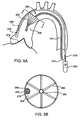
- FIGS. 5A & 5B show a side and axial view, respectively, of a percutaneously delivered temporary valve with a separate bypass catheter and made in accordance with the present invention.
- the separate bypass catheter allows a tool to pass the temporary valve and reach a work area, such as a heart valve.
- the temporary valve system 260 comprises a temporary valve 262 disposed on an elongate element 264.
- the temporary valve 262 can be located in the ascending aortic arch 266.
- a bypass catheter 268 is installed in the vessel parallel to the temporary valve system 260.
- the bypass catheter 268 has a lumen 270 for passage of the tool assembly 272 past the temporary valve 262 to the work area, such as at the aortic valve 274.
- the elongate element 264 can also have at least one lumen so that multiple tools can be used in the work area at one time.
- the tool assembly 272 comprises a tool 276, a shaft 278, and a tool connection 280.
- the tool assembly 272 can be any device required to carry out a percutaneous procedure, such as a catheter, an imaging device, a valve resection device, a replacement valve carrying device, or the like.
- FIG. 5B shows the axial view at section A-A of FIG. 5A with the temporary valve expanded and blocking flow during diastole.
- the struts 282 are spread out from the elongate element 264 and the membrane 284 blocks flow.
- the bypass catheter 268 passes between the struts 282 and the membrane 284 enfolds the bypass catheter 268 to prevent substantial flow along the outside,of the bypass catheter 268.
- the temporary valve system 260 is used in replacement of a native aortic valve with a prosthetic aortic valve. An incision is made inguinally and the bypass catheter 268 advanced through the femoral artery until the distal end is near the work area at the aortic valve 274. The temporary valve system 260 is advanced through the femoral artery until the temporary valve 262 is located in the ascending aorta 266.
- the temporary valve system 260 can be introduced through a catheter.
- the elongate member 264 of the temporary valve system 260 can include a lumen for introduction of additional tools to be used during the operation.
- the temporary valve 262 is deployed from a collapsed state used for insertion to a deployed state in which the temporary valve 262 alternately opens and closes to block and allow blood flow.
- a valve resection tool is advanced through the lumen 270 of the bypass catheter 268, the native aortic valve is removed, and the valve resection tool is withdrawn. With no aortic valve present, the temporary valve 262 provides valve function.
- a valve implantation tool is advanced through the lumen 270 of the bypass catheter 268, the prosthetic aortic valve is installed, and the valve implantation tool is withdrawn.
- the temporary valve 262 can be placed in the collapsed state, the temporary valve system 260 withdrawn from the patient, and the bypass catheter 268 withdrawn from the patient.
- the bypass catheter 268 can be withdrawn from the patient and the temporary valve system 260 can be left in place for days or weeks while the prosthetic aortic valve heals in place, the temporary valve 262 relieving the load on the prosthetic aortic valve during the healing process. After the healing is sufficient, the temporary valve 262 can be returned to the collapsed configuration and the temporary valve system 260 withdrawn from the patient.
- Use of the temporary valve 262 during the healing process can allow use of a sutureless prosthetic valve, rather than a prosthetic valve requiring a sewing cuff and multiple knotted sutures to anchor the prosthetic valve until ingrowth of scar tissue occurs. This can reduce the time required and degree of difficulty of the valve replacement procedure.
- FIGS. 6A & 6B show a deployment system for a temporary valve in the collapsed and deployed state, respectively, for a percutaneously delivered temporary valve made in accordance with the present invention.
- a moveable sheath is employed to restrain the temporary valve during insertion into and withdrawal from the patient.
- FIG. 6A shows a sheath 300 slidably mounted along the elongate body 302 at the distal tip 306 of a temporary valve system.
- FIG. 6B shows the sheath 300 moved toward the distal tip 306 of the elongate body 302, deploying the temporary valve 304.
- the sheath 300 maintains the temporary valve 304 in a collapsed state so the temporary valve 304 can be moved through a body lumen to the point of use.
- the sheath 300 completely covers the temporary valve 304.
- the sheath 300 partially covers the temporary valve 304.
- the sheath 300 can be moved by a wire (not shown) within a lumen of the elongate body 302.
- the wire pushes the sheath 300 toward the distal tip 306 of the elongate body 302 to deploy the temporary valve 304 for use.
- the wire pulls the sheath 300 away from the distal tip 306 of the elongate body 302 to collapse the temporary valve 304 for withdrawal.
- Those skilled in the art will appreciate that numerous mechanisms are possible to shift the temporary valve between the deployed and collapsed state.
- FIG. 7 shows an axial view of a percutaneously delivered temporary valve having mixed stiffness struts made in accordance with the present invention.
- the temporary valve 322 is shown permitting flow through the body lumen 324.
- the struts are divided into two groups, centering struts 320 to maintain the temporary valve 322 centered within the body lumen 324 and flow struts 326 to allow flow past the temporary valve 322.
- the centering struts 320 alternate with the flow struts 326.
- the strut pattern could be selected to fit a particular application, e.g., two centering struts could be provided for every flow strut to hold the temporary valve more firmly, or two flow struts could be provided for every flow strut to assure greater flow.
- the centering struts 320 are relatively stiff and do not move with the pumping of the heart.
- the flow struts 326 are relatively flexible, bending in toward and out away from the elongate member 328 to alternately allow and block flow.
- FIGS. 8A & 8B show a side and axial view, respectively, of a percutaneously delivered temporary valve having mixed stiffness strut groups made in accordance with the present invention.
- Mixed stiffness strut groups can be used to allow for the difference in force on the temporary valves from flexure of the elongate element or characteristics of the body lumen for a particular patient.
- the temporary valve comprises at least a first region and a second region, and the centering struts in the first region have a first stiffness and the centering struts in the second region have a second stiffness.
- Different patients have different aorta dimensions, so it is desirable to fit the temporary valve to a particular patient's characteristics.
- FIG. 8A shows a temporary valve assembly 340, comprising an elongate member 342 and a temporary valve 344, with the temporary valve 344 located in the ascending aorta 346.
- the elongate member 342 can be preformed to ease insertion in the path around the bend from the descending aorta 348 through the aortic arch 350 into the ascending aorta 346.
- the severity of the bend will cause the elongate member 342 to apply more force on the temporary valve outer region 352 and less force on the temporary valve inner region 354, tending to move the elongate member 342 off center. This will decrease the effectiveness of the temporary valve 344 and result in the temporary valve 344 shifting within the ascending aorta 346 as the heart beats.
- the strut characteristics for the inner and outer regions can be selected to account for the force difference.
- FIG. 8B shows an axial view of the temporary valve 344 from FIG. 8A at the section A-A, the temporary valve 344 is shown permitting flow through the body lumen 356.
- the temporary valve 344 comprises a membrane 366, inner centering struts 360, outer centering struts 358, and flow struts 362.
- the centering struts 360, 358 maintain contact with the vessel wall to center the elongate element 342, and the flow struts 362 control flow through the temporary valve 344.
- the design of the centering struts in the temporary valve outer region 352 and the temporary valve inner region 354 are different to account for the force difference from the elongate member 342.
- the outer centering struts 358 are stiffer to resist the greater force, while the inner centering struts 360 are more flexible to resist the lesser force.
- the flow struts 362 are even more flexible, bending in toward and out away from the elongate member 364 to alternately allow and block flow.
- the desired strut stiffness can be obtained by the strut thickness, material characteristics, or a combination thereof.
- the strut characteristics can be selected to provide additional design options.
- the centering struts can be grouped in thirds of the temporary valve, with the centering struts in one third having a different stiffness from the other two thirds, or with the centering struts in each of the thirds having a different stiffness.
- the centering struts can be grouped in quarters of the temporary valve, with a selected stiffness for each of the quarters.
- FIG. 9 shows a percutaneously delivered temporary valve having centering balloons made in accordance with the present invention.
- the temporary valve assembly 380 comprises an elongate member 382, a temporary valve 384 disposed on the elongate member 382, and a centering balloon 386 supported by braces 388.
- the braces 388 are collapsible, and include a passage (not shown) communicating between a lumen in the elongate member 382 and the interior of the centering balloon 386 for inflation of the centering balloon 386.
- the braces 388 are made of the same material and are integral to the centering balloon 386. The braces 388 inflate with the centering balloon 386.
- the braces 388 are made of a metal, such as stainless steel or a shape metal alloy like nitinol.
- the centering balloon 386 can be manufactured from a material such as polyethylene, polyethylene terephthalate (PET), nylon, Pebax® polyether-block co-polyamide polymers, or the like.
- the seating edge 390 of the temporary valve 384 is aligned with the inner edge 392 of the centering balloon 386.
- the vessel wall is protected from impact with the temporary valve 384 as the temporary valve 384 alternately moves to block and allow flow, because the seating edge 390 contacts the centering balloon 386, rather than the vessel wall.
- the mating surfaces of the seating edge 390 and the inner edge 392 can be designed to provide a superior seal.
- one or more auxiliary centering balloons 394 can be disposed along the elongate member 382 of the temporary valve assembly 380 to center the elongate member 382 within the body lumen 396.
- the auxiliary centering balloons 394 can be placed proximally or distally of the temporary valve 384.
- the auxiliary braces 398 are collapsible, and include a passage (not shown) communicating between a lumen in the elongate member 382 and the interior of the auxiliary centering balloons 394 for inflation of the auxiliary centering balloons 394.
- the auxiliary braces 398 are made of the same material and are integral to the auxiliary centering balloon 394.
- the auxiliary braces 398 inflate with the auxiliary centering balloon 394.
- the auxiliary braces 398 are made of a metal, such as stainless steel or a shape metal alloy like nitinol.
- the auxiliary centering balloon 394 can be manufactured from a material such as polyethylene, polyethylene terephthalate (PET), nylon, Pebax® polyether-block co-polyamide polymers, or the like.
- PET polyethylene terephthalate
- nylon nylon
- Pebax® polyether-block co-polyamide polymers or the like.
- Filter material 400 can be connected across opening in the auxiliary centering balloon 394 to remove embolic material during an operation.
- placement of the auxiliary centering balloon 394 including filter material 400 upstream of the brachiocephalic artery prevents embolic material from entering the arteries branching from the aortic arch, reducing the risk of stroke.
- the filter material 400 can be any non-thrombogenic mesh , such as polyethylene mesh, Dacron polyester mesh, nylon mesh, textile fabrics, spun bonded polyolefin, expanded polytetrafluoroethylene, or nonwoven materials.
- the pore size of the filter material 400 can be of a size sufficient to block and capture any micro- and macro-emboli which may flow downstream from the site of the operation, but large enough that blood flow is not impeded.
- the pore size can be less than about 500 microns, typically about 50 to 250 microns.
- a separate filtering device such as the Scion Cardio-Vascular SCI-PRO® guide wire based retrieval device from Scion Cardio-Vascular, Inc., of Miami, Florida, can be inserted in parallel with the temporary valve assembly to remove embolic material during an operation.
- FIGS. 10A & 10B show a side and axial view, respectively, of an eccentric percutaneously delivered temporary valve made in accordance with the present invention.
- the irregular shape of the temporary valve provides a custom fit depending on the body lumen geometry of a particular patient.
- the temporary valve assembly 420 comprises an elongate element 422 and a temporary valve 424, the temporary valve 424 further comprising struts 426 and a membrane 428.
- a moveable sheath 430 can be slidably mounted on the elongate element 422 to cover the temporary valve 424 while the temporary valve assembly 420 is moved through a body lumen.
- the eccentric lobe 432 of the temporary valve 424 can be disposed against the outer curve of the ascending aorta to increase the contact area with the outer vessel wall.
- the temporary valve can be elliptical to orient the elongate element at an angle relative to the axis of the body lumen.
- the temporary valve 424 can be different shapes and sizes to fit the varied anatomies of different patients.
- FIG. 11 shows a flow chart for a method of use for a percutaneously delivered temporary valve made in accordance with the present invention.
- a temporary valve assembly is provided, the temporary valve assembly comprising an elongate element and a temporary valve disposed near the distal end of the elongate element, the elongate element including a lumen.
- the temporary valve can be sized to a particular patient. The temporary valve assembly is inserted into the patient so the temporary valve is located in the ascending aorta of the patient 442.
- the temporary valve can be sized to the particular patient by trial fitting in the ascending aorta.
- the temporary valve can be sized to the particular patient by pre-measuring the patient.
- the temporary valve is deployed 444.
- the native aortic valve is removed past the temporary valve through the lumen of the elongate element 446 and a prosthetic aortic valve implanted past the temporary valve through the lumen of the elongate element 448.
- the temporary valve is collapsed 450 and the temporary valve assembly removed from the patient 452.
- the temporary valve assembly can be retained in the patient until the prosthetic aortic valve heals in and temporary valve assembly removed after a few days or weeks.
- the temporary valve assembly can be removed immediately.
- FIGS. 1-11 illustrate specific applications and embodiments of the present invention, and is not intended to limit the scope of the present disclosure or claims to that which is presented therein.
Description
- The technical field of this disclosure is medical devices, particularly, a percutaneously delivered temporary valve assembly.
- Heart valves, such as the aortic valve, are sometimes damaged by diseases or by aging which can cause problems with the proper function of the valve. Heart valve disease generally takes one of two forms: stenosis, in which a valve does not open completely or the opening is too small, resulting in restricted blood flow; or insufficiency, in which blood leaks retrograde across the valve that should be closed. Valve replacement may be required in severe cases to restore cardiac function. In common practice, replacement requires open-heart surgery with its attendant risks, expense, and extended recovery time. Open-heart surgery also requires cardiopulmonary bypass with risk of thrombosis, stroke, and infarction.
- Catheter based valve replacement has been proposed as a way to effect valve replacement percutaneously and to avoid open-heart surgery. Such procedures involve excision of the native valve and replacement of the native valve with a prosthetic valve, or installation of a prosthetic valve over the native valve. To avoid cardiopulmonary bypass, the catheter based valve replacement is performed on a beating heart. Following excision of the native valve, no valve is present to preserve the pumping action of the heart while the permanent prosthetic valve is being implanted. An additional consideration in both open-heart and catheter based valve replacement is the healing process after the prosthetic valve is implanted. After the valve replacement procedure, scar tissue must form around the sewing cuff to secure the prosthetic valve in position. In current practice, multiple knotted sutures anchor the prosthetic valve in place until ingrowth of scar tissue into the sewing cuff takes over the load bearing function. However, the placement of knotted sutures by catheter can be very difficult and time consuming.
- Artificial heart valves for temporary use are known in the art, but present certain problems. Some designs are complex, inflating and deflating balloons to alternately block and permit flow. Such designs require complex sensing and control systems. Other designs fail to provide access for tools that must reach the valve site for removal of the native valve and placement of the prosthetic valve. Yet other designs require elaborate supporting frames to hold the valve portion.
-
U.S. Patent No. 3,671,979 to Moulopoulos discloses an artificial heart valve for implantation in close proximity to a malfunctioning or damaged natural aortic or mitral heart valve by remote means without performing an open chest or other major surgical operation, the artificial heart valve comprising a flexible membrane in the form of an umbrella. -
U.S. Patent No. 4,056,854 to Boretos et al. discloses an artificial valve remotely placeable in a blood vessel without major surgery to supplant the function of a malfunctioning natural valve including an expansible check valve remotely placed in a constricted configuration through the vessel and a remotely removable constraint for selective expansion of the check valve for sealing engagement thereof within the walls of the vessel at the desired location.U.S. Patent No. 4,705,507 to Boyles discloses an arterial catheter of the multi-lumen type having an inflatable balloon portion to wedge the catheter in place against the arterial wall. Multi-infusions are allowed through the segmented multi-lumens. The catheter is designed to allow blood to flow in the arterial system with the catheter in place. During diastolic phases, the blood flow will be closed off with movable plastic valves. -
U.S. Patent Application No. 20020151970 to Garrison et al. discloses a valve implantation system having a valve displacer for displacing and holding the native valve leaflets open wherein a replacement valve may be attached to the valve displacer before or after introduction and may be positioned independent of the valve displacer and wherein a temporary valve mechanism may be used to provide temporary valve functions during and after deployment of the valve displacer. WIPOInternational Publication No. WO 00/44313
It would be desirable to have a percutaneously delivered temporary valve that would overcome the above disadvantages. - According to the invention, there is provided a
temporary valve system comprising: - an elongate element; and
- a temporary valve disposed on the elongate element, the temporary valve comprising struts and a membrane attached to the struts, wherein the struts are moveable to allow the temporary valve to alternate between an open position and a closed position in response to a differential pressure across the temporary valve.
- The temporary valve may be an umbrella-like temporary valve.
- One object of the present invention is to provide a percutaneously delivered temporary valve to provide valve function during valve replacement.
- Another object of the present invention is to provide a percutaneously delivered temporary valve to permitting access for tools at the valve site during valve replacement.
- Another object of the present invention is to provide a percutaneously delivered temporary valve to supplement valve function after valve replacement.
- Another object of the present invention is to provide a percutaneously delivered temporary valve to provide load relief until adequate scar tissue ingrowth has taken place around a prosthetic valve after valve replacement.
- The foregoing and other features and advantages of the invention will become further apparent from the following detailed description of the presently preferred embodiments, read in conjunction with the accompanying drawings. The detailed description and drawings are merely illustrative of the invention, rather than limiting the scope of the invention being defined by the appended claims.
-
-
FIGS. 1A-1C show a percutaneously delivered temporary valve system made in accordance with the present invention. -
FIG. 2 shows a detailed view of a percutaneously delivered temporary valve made in accordance with the present invention. -
FIGS. 3A-3C show embodiments of a strut assembly for a percutaneously delivered temporary valve made in accordance with the present invention. -
FIG. 4 shows a percutaneously delivered temporary valve having a central lumen made in accordance with the present invention. -
FIGS. 5A & 5B show a side and axial view, respectively, of a percutaneously delivered temporary valve with a separate bypass catheter and made in accordance with the present invention. -
FIGS. 6A & 6B show a deployment system for a temporary valve in the collapsed and deployed state, respectively, for a percutaneously delivered temporary valve made in accordance with the present invention.FIG. 7 shows an axial view of a percutaneously delivered temporary valve having mixed stiffness struts made in accordance with the present invention. -
FIGS. 8A & 8B show a side and axial view, respectively, of a percutaneously delivered temporary valve having mixed stiffness strut groups made in accordance with the present invention. -
FIG. 9 shows a percutaneously delivered temporary valve having centering balloons made in accordance with the present invention. -
FIGS. 10A & 10B show a side and axial view, respectively, of an eccentric percutaneously delivered temporary valve made in accordance with the present invention. -
FIG. 11 shows a flow chart for a method of use for a percutaneously delivered temporary valve made in accordance with the present invention. -
FIGS. 1A-1C , in which like elements share like reference numbers, shows a percutaneously delivered temporary valve system.FIG. 1A shows the temporary valve disposed in the ascending aorta, andFIGS. 1B & 1C show the temporary valve during diastole and systole, respectively. - Referring to
FIG. 1A , thetemporary valve system 100 comprises atemporary valve 102 connected to anelongate element 104. In the example shown, thetemporary valve 102 is located in the ascendingaorta 106 between theaortic valve 108 and thebrachiocephalic artery 110.FIG. 1B shows thetemporary valve 102 in the open position seating against the aortic wall to block retrograde blood flow during diastole.FIG. 1C shows thetemporary valve 102 in the closed position at a reduced diameter to allow anterograde blood flow during systole. Thetemporary valve 102 alternates passively between the open and closed positions in response to the differential pressure across the valve. In one embodiment, thetemporary valve 102 is an umbrella-like valve and theelongate element 104 includes at least one lumen. -
FIG. 2 shows a detailed view of a percutaneously delivered temporary valve made in accordance with the present invention. Thetemporary valve 102 comprisesstruts 120 and amembrane 122 attached to thestruts 120. Thetemporary valve 102 can be attached to theelongate element 104 at thevalve apex 124 with the distal end of thetemporary valve 102 pointed toward the heart in the direction of normal flow. Anoptional skirt 126 can be attached at theseating edge 128 of thetemporary valve 102 to provide additional sealing surface against the vessel wall. - Those skilled in the art will appreciate that the elements of the
temporary valve 102 can be joined in a number of ways. Thestruts 120 can be located on the outside or the inside of themembrane 122, or can be internal to or fabricated as part of themembrane 122. Themembrane 122 can be attached to thestruts 120 with adhesive, by sewing with a wire or fiber filament, or by a combination of such methods. Flow at thevalve apex 124 can be prevented by sealing themembrane 122 at thevalve apex 124 with a sealant or adhesive, by tying or wrapping themembrane 122 with a wire or fiber filament, or by a combination of such methods. - The
temporary valve 102 can be located on theelongate element 104 at a distance from thedistal tip 130 so that thetemporary valve 102 is located in the ascending aorta during use. In one embodiment, thetemporary valve 102 is between about 1 and 8 centimeters from thedistal tip 130, and more particularly at about 5 centimeters. - The
membrane 122 can be any flexible, collapsible sheet material, which is generally impermeable to flow, biocompatible, and non-thrombogenic. Examples of suitable synthetic polymers and co-polymers include, but are not limited to, segmented polyurethane with a small percentage of added silicone, reinforced polyurethane, coated nylon such as sheeted, non-braided coated nylon, and the like. Themembrane 122 can also be made of a fixed collagenous membrane of animal origin, such as pericardium, or a membrane generated synthetically through recombinant DNA technology in yeast. In one embodiment, themembrane 122 can be coated with an anti-thrombotic material to further enhance biocompatibility. The anti-thrombotic material can be a natural molecule, such as heparin, or synthetics, such as the conducting polymer polypirrole. - The
struts 120 can be hinged at theelongate element 104 or fixedly attached to theelongate element 104. In one embodiment, thestruts 120 can be rigid and hinges provided where eachstrut 120 meets theelongate element 104 at the valve apex 124: the hinge allows thetemporary valve 102 to alternate between the open and closed position. The hinge can be a separate element connecting thestruts 120 to theelongate element 104, or can be a portion of theflexible membrane 122 between thestruts 120 and theelongate element 104. In another embodiment, thestruts 120 can be flexible and fixedly attached to the elongate element 104: thestruts 120 flex to allow thetemporary valve 102 to alternate between the open and closed position. - The
struts 120 can be rigid or flexible depending on the particular application. Examples of suitable materials include, but are not limited to, titanium, stainless steel, shape memory alloys such as nitinol, hard plastic such as polypropylene, or the like. Thestruts 120 can be straight or curved, and can perform multiple functions, such as both maintaining the geometry of themembrane 122 and centering the elongate element. 104 within the aorta. Struts of different shapes, materials and flexibilities can be combined in a single temporary valve. For example, less flexible struts can alternate with flexible struts. The less flexible struts hold the temporary'valve in position against the aortic wall and center the elongate element, while the flexible struts move in response to the heart pumping to alternately block and allow blood flow through the temporary valve. The number ofstruts 120 can be varied as required for a particular application. - The
elongate element 104 can be a catheter, guide wire, or any other elongate element to deliver thetemporary valve 102 into a vessel lumen where temporary valve function is required. In one example, theelongate element 104 can be inserted inguinally into the femoral artery and advanced until the distal end carrying thetemporary valve 120 is in the ascending aorta near the aortic valve. Theelongate element 104 can have a solid cross section, or can include one or more lumens extending the length or the partial length of theelongate element 104. A lumen from the proximal end of theelongate element 104 to thedistal tip 130 can provide access from outside the patient, past the temporary valve, to the work area at the heart or heart valve. The lumens can be used for inserting tools, injecting chemicals, sampling fluids, inserting sensors and sensor cables, or actuating the temporary valve with fluids, gases, electrical cables, or wires. Theelongate element 104 can be preformed to a curved shape which will more easily follow the curves of the body lumen into which theelongate element 104 is inserted. Thedistal tip 130 can be tilted at a fixed angle to the long axis of theelongate element 104, or steerable, to direct thedistal tip 130 toward the work area. Theelongate element 104 can also carry additional elements along its length, such as filters to retain embolic material, or centering balloons or fingers to center theelongate element 104 in the body lumen. One or more radiopaque markers can be provided on theelongate element 104 for location of the temporary valve assembly by fluoroscopy during use. - The
optional skirt 126 can provide additional sealing surface against the aortic wall and can protect the aortic wall from the tips of thestruts 120 at theseating edge 128. Theskirt 126 can be the' same or different material than themembrane 122. Exemplary materials for theskirt 126 include the materials used in themembrane 122, such as segmented polyurethane with a small percentage of added silicone, reinforced polyurethane, coated nylon such as sheeted, non-braided coated nylon, fixed collagenous membrane of animal origin, and the like. In another embodiment, theskirt 126 can be made of soft silicone. Theskirt 126 can be thicker than themembrane 122 and can have a defined profile, such as circumferential external ribbing, to increase sealing at the aortic wall. In one embodiment, theskirt 126 can be a conformable, slightly stiff cuff. In another embodiment, theskirt 126 can be inflatable. In another embodiment, theskirt 126 can provide padding between the ends of the struts and the aortic wall to protect the aortic wall. -
FIGS. 3A-3C show embodiments of a strut assembly for a percutaneously delivered temporary valve made in accordance with the present invention. In this embodiment, the strut assembly comprises a strut collar and a plurality of struts. The strut assembly provides improved fabrication and assembly. The strut assembly can be manufactured from a single piece of tubing. The strut assembly can be placed on the elongate element in a single operation, installing all the struts at once, rather than one at a time. -
FIG. 3A shows a strut assembly in the fully formed configuration. Thestrut assembly 200 comprises astrut collar 202 and struts 204. The flexibility of thestruts 204 allows thestruts 204 to be compressed for introduction into the body lumen, to expand on release, and to alternately block and allow blood flow. In one embodiment, thestrut collar 202 and struts 204 are one piece. In another embodiment, thestruts 204 can be fabricated individually and attached to thestrut collar 202. Thestrut collar 202 can be installed'on the elongate element (not shown), before or after the membrane forming the temporary valve is attached to thestruts 204. Dimples, cuts, or slots can be formed in thestrut collar 202 so that thestrut collar 202 attaches firmly to the elongate element. Thestruts 204 can have the same flexibility, or can have various flexibilities. Flexibility can be varied by the material properties and treatment, strut thickness, or a combination thereof. -
FIG. 3B shows a strut assembly in the cut, but unformed, configuration. In one embodiment, thestrut assembly 200 is cut from a nitinol shape metal alloy tube with a laser cutter or electrical discharge machining (EDM). The angle between thestrut collar 202 and thestruts 204, plus any shaping of thestruts 204, can be performed by heat setting. -
FIG. 3C shows a strut assembly having curved struts in a formed configuration. In this embodiment, thestruts 204 have a soft S-shaped curve. The S-shaped curve is parallel or nearly parallel the vessel at the free end of thestruts 204 and so provides an increased vessel contact area during use. The S-shaped curve also provides good outward spring, since the struts are parallel or nearly parallel thestrut collar 202 where thestruts 204 attach to thestrut collar 202. Thestrut assembly 200 can be cut from a single nitinol shape metal alloy tube and thestruts 204 formed by heat setting. Those skilled in the art will appreciate that a number of shapes can be used for thestruts 204, such as straight, concave, convex, S-shaped, sigmoidal, or any combination thereof. In one embodiment, thestruts 204 can be straight along most of their length, ending in a medially-concave bend a the distal end to reduce wear on the luminal surface of the aorta. -
FIG. 4 shows a percutaneously delivered temporary valve having a central lumen made in accordance with the present invention. The central lumen allows a tool to pass the temporary valve and reach a work area, such as a heart valve. - The
temporary valve system 218 comprises atemporary valve 220 disposed on anelongate element 226, theelongate element 226 having alumen 230. Thetemporary valve 220 can be located in the ascendingaortic arch 222. Theelongate element 226, shown cut away to revealtool assembly 228, has alumen 230 for passage of thetool assembly 228 past thetemporary valve 220 to the work area, such as at theaortic valve 238. Thetool assembly 228 comprises atool 232, ashaft 234, and atool connection 236. Thetool assembly 228 can be any device required to carry out a percutaneous procedure, such as a catheter, an imaging device, a valve resection device, a replacement valve carrying device, or the like. - In this example, the
temporary valve system 218 is used in replacement of a native aortic valve with a prosthetic aortic valve. An incision is made inguinally and thetemporary valve system 218 advanced through the femoral artery until thetemporary valve 220 is located in the ascendingaorta 222. In one embodiment, thetemporary valve system 218 can be introduced through a catheter. Thetemporary valve 220 is deployed from a collapsed state used for insertion to a deployed state in which thetemporary valve 220 alternately opens and closes to block and allow blood flow. A valve resection tool is advanced through thelumen 230 of theelongate element 226, the native aortic valve is removed, and the valve resection tool is withdrawn. With no aortic valve present, thetemporary valve 220 provides valve function. A valve implantation tool is advanced through thelumen 230 of theelongate element 226, the prosthetic aortic valve is installed, and the valve implantation tool is withdrawn. In one embodiment, thetemporary valve 220 can be placed in the collapsed state and thetemporary valve system 218 withdrawn from the patient. In another embodiment, thetemporary valve system 218 can be left in place for days or weeks while the permanent prosthetic aortic valve heals in place, thetemporary valve 220 relieving load on the prosthetic aortic valve during the healing process. After the healing is sufficient, thetemporary valve 220 can be placed in the collapsed state and thetemporary valve system 218 withdrawn from the patient. -
FIGS. 5A & 5B show a side and axial view, respectively, of a percutaneously delivered temporary valve with a separate bypass catheter and made in accordance with the present invention. The separate bypass catheter allows a tool to pass the temporary valve and reach a work area, such as a heart valve. - The
temporary valve system 260 comprises atemporary valve 262 disposed on anelongate element 264. Thetemporary valve 262 can be located in the ascendingaortic arch 266. Abypass catheter 268 is installed in the vessel parallel to thetemporary valve system 260. Thebypass catheter 268 has alumen 270 for passage of thetool assembly 272 past thetemporary valve 262 to the work area, such as at theaortic valve 274. In one embodiment, theelongate element 264 can also have at least one lumen so that multiple tools can be used in the work area at one time. Thetool assembly 272 comprises atool 276, ashaft 278, and atool connection 280. Thetool assembly 272 can be any device required to carry out a percutaneous procedure, such as a catheter, an imaging device, a valve resection device, a replacement valve carrying device, or the like. -
FIG. 5B shows the axial view at section A-A ofFIG. 5A with the temporary valve expanded and blocking flow during diastole. Thestruts 282 are spread out from theelongate element 264 and themembrane 284 blocks flow. Thebypass catheter 268 passes between thestruts 282 and themembrane 284 enfolds thebypass catheter 268 to prevent substantial flow along the outside,of thebypass catheter 268. - In this example, the
temporary valve system 260 is used in replacement of a native aortic valve with a prosthetic aortic valve. An incision is made inguinally and thebypass catheter 268 advanced through the femoral artery until the distal end is near the work area at theaortic valve 274. Thetemporary valve system 260 is advanced through the femoral artery until thetemporary valve 262 is located in the ascendingaorta 266. In one embodiment, thetemporary valve system 260 can be introduced through a catheter. In another embodiment, theelongate member 264 of thetemporary valve system 260 can include a lumen for introduction of additional tools to be used during the operation. Thetemporary valve 262 is deployed from a collapsed state used for insertion to a deployed state in which thetemporary valve 262 alternately opens and closes to block and allow blood flow. A valve resection tool is advanced through thelumen 270 of thebypass catheter 268, the native aortic valve is removed, and the valve resection tool is withdrawn. With no aortic valve present, thetemporary valve 262 provides valve function. - A valve implantation tool is advanced through the
lumen 270 of thebypass catheter 268, the prosthetic aortic valve is installed, and the valve implantation tool is withdrawn. In one embodiment, thetemporary valve 262 can be placed in the collapsed state, thetemporary valve system 260 withdrawn from the patient, and thebypass catheter 268 withdrawn from the patient. In another embodiment, thebypass catheter 268 can be withdrawn from the patient and thetemporary valve system 260 can be left in place for days or weeks while the prosthetic aortic valve heals in place, thetemporary valve 262 relieving the load on the prosthetic aortic valve during the healing process. After the healing is sufficient, thetemporary valve 262 can be returned to the collapsed configuration and thetemporary valve system 260 withdrawn from the patient. Use of thetemporary valve 262 during the healing process can allow use of a sutureless prosthetic valve, rather than a prosthetic valve requiring a sewing cuff and multiple knotted sutures to anchor the prosthetic valve until ingrowth of scar tissue occurs. This can reduce the time required and degree of difficulty of the valve replacement procedure. -
FIGS. 6A & 6B show a deployment system for a temporary valve in the collapsed and deployed state, respectively, for a percutaneously delivered temporary valve made in accordance with the present invention. In this example, a moveable sheath is employed to restrain the temporary valve during insertion into and withdrawal from the patient. -
FIG. 6A shows asheath 300 slidably mounted along theelongate body 302 at thedistal tip 306 of a temporary valve system.FIG. 6B shows thesheath 300 moved toward thedistal tip 306 of theelongate body 302, deploying thetemporary valve 304. Thesheath 300 maintains thetemporary valve 304 in a collapsed state so thetemporary valve 304 can be moved through a body lumen to the point of use. In one embodiment, thesheath 300 completely covers thetemporary valve 304. In another embodiment, thesheath 300 partially covers thetemporary valve 304. Thesheath 300 can be moved by a wire (not shown) within a lumen of theelongate body 302. The wire pushes thesheath 300 toward thedistal tip 306 of theelongate body 302 to deploy thetemporary valve 304 for use. The wire pulls thesheath 300 away from thedistal tip 306 of theelongate body 302 to collapse thetemporary valve 304 for withdrawal. Those skilled in the art will appreciate that numerous mechanisms are possible to shift the temporary valve between the deployed and collapsed state. -
FIG. 7 shows an axial view of a percutaneously delivered temporary valve having mixed stiffness struts made in accordance with the present invention. Thetemporary valve 322 is shown permitting flow through thebody lumen 324. In this example, the struts are divided into two groups, centeringstruts 320 to maintain thetemporary valve 322 centered within thebody lumen 324 and flow struts 326 to allow flow past thetemporary valve 322. In this example, the centeringstruts 320 alternate with the flow struts 326. Optionally, the strut pattern could be selected to fit a particular application, e.g., two centering struts could be provided for every flow strut to hold the temporary valve more firmly, or two flow struts could be provided for every flow strut to assure greater flow. The centering struts 320 are relatively stiff and do not move with the pumping of the heart. The flow struts 326 are relatively flexible, bending in toward and out away from theelongate member 328 to alternately allow and block flow. -
FIGS. 8A & 8B show a side and axial view, respectively, of a percutaneously delivered temporary valve having mixed stiffness strut groups made in accordance with the present invention. Mixed stiffness strut groups can be used to allow for the difference in force on the temporary valves from flexure of the elongate element or characteristics of the body lumen for a particular patient. The temporary valve comprises at least a first region and a second region, and the centering struts in the first region have a first stiffness and the centering struts in the second region have a second stiffness. Different patients have different aorta dimensions, so it is desirable to fit the temporary valve to a particular patient's characteristics. -
FIG. 8A shows atemporary valve assembly 340, comprising anelongate member 342 and atemporary valve 344, with thetemporary valve 344 located in the ascendingaorta 346. Theelongate member 342 can be preformed to ease insertion in the path around the bend from the descendingaorta 348 through theaortic arch 350 into the ascendingaorta 346. However, the severity of the bend will cause theelongate member 342 to apply more force on the temporary valveouter region 352 and less force on the temporary valveinner region 354, tending to move theelongate member 342 off center. This will decrease the effectiveness of thetemporary valve 344 and result in thetemporary valve 344 shifting within the ascendingaorta 346 as the heart beats. The strut characteristics for the inner and outer regions can be selected to account for the force difference. -
FIG. 8B shows an axial view of thetemporary valve 344 fromFIG. 8A at the section A-A, thetemporary valve 344 is shown permitting flow through thebody lumen 356. Thetemporary valve 344 comprises amembrane 366, inner centeringstruts 360, outer centeringstruts 358, and flow struts 362. The centering struts 360, 358 maintain contact with the vessel wall to center theelongate element 342, and the flow struts 362 control flow through thetemporary valve 344. In this example, the design of the centering struts in the temporary valveouter region 352 and the temporary valveinner region 354 are different to account for the force difference from theelongate member 342. The outer centeringstruts 358 are stiffer to resist the greater force, while the inner centeringstruts 360 are more flexible to resist the lesser force. The flow struts 362 are even more flexible, bending in toward and out away from theelongate member 364 to alternately allow and block flow. The desired strut stiffness can be obtained by the strut thickness, material characteristics, or a combination thereof. - Those skilled in the art will appreciate that the strut characteristics can be selected to provide additional design options. In one embodiment, the centering struts can be grouped in thirds of the temporary valve, with the centering struts in one third having a different stiffness from the other two thirds, or with the centering struts in each of the thirds having a different stiffness. In another embodiment, the centering struts can be grouped in quarters of the temporary valve, with a selected stiffness for each of the quarters.
-
FIG. 9 shows a percutaneously delivered temporary valve having centering balloons made in accordance with the present invention. Thetemporary valve assembly 380 comprises anelongate member 382, atemporary valve 384 disposed on theelongate member 382, and a centeringballoon 386 supported bybraces 388. Thebraces 388 are collapsible, and include a passage (not shown) communicating between a lumen in theelongate member 382 and the interior of the centeringballoon 386 for inflation of the centeringballoon 386. In one embodiment, thebraces 388 are made of the same material and are integral to the centeringballoon 386. Thebraces 388 inflate with the centeringballoon 386. In another embodiment, thebraces 388 are made of a metal, such as stainless steel or a shape metal alloy like nitinol. The centeringballoon 386 can be manufactured from a material such as polyethylene, polyethylene terephthalate (PET), nylon, Pebax® polyether-block co-polyamide polymers, or the like. - The
seating edge 390 of thetemporary valve 384 is aligned with theinner edge 392 of the centeringballoon 386. The vessel wall is protected from impact with thetemporary valve 384 as thetemporary valve 384 alternately moves to block and allow flow, because theseating edge 390 contacts the centeringballoon 386, rather than the vessel wall. The mating surfaces of theseating edge 390 and theinner edge 392 can be designed to provide a superior seal. - In one embodiment, one or more auxiliary centering
balloons 394 can be disposed along theelongate member 382 of thetemporary valve assembly 380 to center theelongate member 382 within thebody lumen 396. The auxiliary centeringballoons 394 can be placed proximally or distally of thetemporary valve 384. The auxiliary braces 398 are collapsible, and include a passage (not shown) communicating between a lumen in theelongate member 382 and the interior of the auxiliary centeringballoons 394 for inflation of the auxiliary centering balloons 394. In one embodiment, the auxiliary braces 398 are made of the same material and are integral to the auxiliary centeringballoon 394. The auxiliary braces 398 inflate with the auxiliary centeringballoon 394. In another embodiment, the auxiliary braces 398 are made of a metal, such as stainless steel or a shape metal alloy like nitinol. The auxiliary centeringballoon 394 can be manufactured from a material such as polyethylene, polyethylene terephthalate (PET), nylon, Pebax® polyether-block co-polyamide polymers, or the like. Those skilled in the art will appreciate that the elongate member can be centered using other elements attached to the elongate member, such as radially projecting collapsible fingers, springs, or the like. -
Filter material 400 can be connected across opening in the auxiliary centeringballoon 394 to remove embolic material during an operation. For aortic valve operations, placement of the auxiliary centeringballoon 394 includingfilter material 400 upstream of the brachiocephalic artery prevents embolic material from entering the arteries branching from the aortic arch, reducing the risk of stroke. Thefilter material 400 can be any non-thrombogenic mesh , such as polyethylene mesh, Dacron polyester mesh, nylon mesh, textile fabrics, spun bonded polyolefin, expanded polytetrafluoroethylene, or nonwoven materials. The pore size of thefilter material 400 can be of a size sufficient to block and capture any micro- and macro-emboli which may flow downstream from the site of the operation, but large enough that blood flow is not impeded. The pore size can be less than about 500 microns, typically about 50 to 250 microns. In another embodiment, a separate filtering device, such as the Scion Cardio-Vascular SCI-PRO® guide wire based retrieval device from Scion Cardio-Vascular, Inc., of Miami, Florida, can be inserted in parallel with the temporary valve assembly to remove embolic material during an operation. -
FIGS. 10A & 10B show a side and axial view, respectively, of an eccentric percutaneously delivered temporary valve made in accordance with the present invention. The irregular shape of the temporary valve provides a custom fit depending on the body lumen geometry of a particular patient. Thetemporary valve assembly 420 comprises anelongate element 422 and atemporary valve 424, thetemporary valve 424 further comprisingstruts 426 and amembrane 428. Amoveable sheath 430 can be slidably mounted on theelongate element 422 to cover thetemporary valve 424 while thetemporary valve assembly 420 is moved through a body lumen. Theeccentric lobe 432 of thetemporary valve 424 can be disposed against the outer curve of the ascending aorta to increase the contact area with the outer vessel wall. In another embodiment, the temporary valve can be elliptical to orient the elongate element at an angle relative to the axis of the body lumen. Those skilled in the art will appreciate that thetemporary valve 424 can be different shapes and sizes to fit the varied anatomies of different patients. -
FIG. 11 shows a flow chart for a method of use for a percutaneously delivered temporary valve made in accordance with the present invention. At 440, a temporary valve assembly is provided, the temporary valve assembly comprising an elongate element and a temporary valve disposed near the distal end of the elongate element, the elongate element including a lumen. In one embodiment, the temporary valve can be sized to a particular patient. The temporary valve assembly is inserted into the patient so the temporary valve is located in the ascending aorta of thepatient 442. In one embodiment, the temporary valve can be sized to the particular patient by trial fitting in the ascending aorta. In another embodiment, the temporary valve can be sized to the particular patient by pre-measuring the patient. The temporary valve is deployed 444. The native aortic valve is removed past the temporary valve through the lumen of theelongate element 446 and a prosthetic aortic valve implanted past the temporary valve through the lumen of theelongate element 448. The temporary valve is collapsed 450 and the temporary valve assembly removed from thepatient 452. In one embodiment, the temporary valve assembly can be retained in the patient until the prosthetic aortic valve heals in and temporary valve assembly removed after a few days or weeks. In one embodiment, the temporary valve assembly can be removed immediately. - It is important to note that
FIGS. 1-11 illustrate specific applications and embodiments of the present invention, and is not intended to limit the scope of the present disclosure or claims to that which is presented therein. Upon reading the specification and reviewing the drawings hereof, it will become immediately obvious to those skilled in the art that myriad other embodiments of the present invention are possible, and that such embodiments are contemplated and fall within the scope of the present claims.
Claims (24)
- A temporary valve system comprising:an elongate element (104); anda temporary valve (102) disposed on the elongate element (104), the temporary valve (102) comprising struts (120) and a membrane (122) attached to the struts (120), wherein the struts (120) are moveable to allow the temporary valve (102) to alternate between an open position and a closed position in response to a differential pressure across the temporary valve.
- The temporary valve system of claim 1 wherein the elongate element (104) includes at least one lumen.
- The temporary valve system of any preceding claim wherein the struts (120) are attached to a strut collar (202), the strut collar (202) being disposed about the elongate element (104).
- The temporary valve system of claim 3 wherein the strut collar (202) and struts (204) are a single piece.
- The temporary valve system of any preceding claim wherein strut shape is selected from the group consisting of straight, concave, convex, S-shaped, sigmoidal, and combinations thereof.
- The temporary valve system of any of claims 1 to 5 wherein the elongate element (104) has a distal tip (130), and the temporary valve (102) is between 1 and 8 centimeters from the distal tip (130).
- The temporary valve system of claim 6 wherein the temporary valve (102) is 5 centimeters from the distal tip (130).
- The temporary valve system of any preceding claim wherein the struts (120) comprise centering struts (320) and flow struts (326).
- The temporary valve system of claim 8 wherein the centering struts (320) alternate with the flow struts (326).
- The temporary valve system of claim 9 wherein the temporary valve (344) comprises at least a first region (352) and a second region (354), and the centering struts (320) in the first region (352) have a first stiffness and the centering struts in the second region (354) have a second stiffness.
- The temporary valve system of any preceding claim further comprising a bypass catheter (268), the bypass catheter (268) being locatable between the struts (282).
- The temporary valve system of any preceding claim, wherein the temporary valve is an umbrella-like temporary valve (102).
- The temporary valve system of any preceding claim, the temporary valve (102) further comprising a seating edge (128) and a skirt (126) attached to the seating edge (128).
- The temporary valve system of any preceding claim wherein the temporary valve (102) is coated with an anti-thrombotic material.
- The temporary valve system of any preceding claim wherein the elongate element (104) has a long axis and a distal tip (130), and the distal tip (130) is angled with respect to the long axis.
- The temporary valve system of any preceding claim wherein the elongate element (104) has a distal tip (130), and the distal tip (130) is steerable.
- The temporary valve system of any preceding claim wherein the elongate element (104) has a distal tip (130), and the temporary valve (102) is a distance from the distal tip (130) that locates the temporary valve (102) in an ascending aorta during use.
- The temporary valve system of any preceding claim further comprising means for deploying the temporary valve.
- The temporary valve system of any preceding claim further comprising a sheath (300), the sheath (300) being slidably mounted along the elongate body (302), the sheath (300) having a first position and a second position, wherein the sheath (300) at least partially covers the temporary valve (304) in the first position and the sheath (300) deploys the temporary valve (304) in the second position.
- The temporary valve system of any preceding claim further comprising means for centering the elongate member in a body lumen.
- The temporary valve system of any preceding claim further comprising a centering balloon (386), the centering balloon (386) being disposed on the elongate member (382).
- The temporary valve system of claim 21 wherein the temporary valve (384) has a seating edge (390), the seating edge (390) being aligned to contact the centering balloon (386).
- The temporary valve system of claim 21 or 22 wherein the centering balloon (394) includes an opening, the opening being covered with filter material (400).
- The temporary valve system of any of claims 1 to 19, wherein the temporary valve (424) is eccentric.
Applications Claiming Priority (2)
| Application Number | Priority Date | Filing Date | Title |
|---|---|---|---|
| US46693803P | 2003-04-30 | 2003-04-30 | |
| US466938P | 2003-04-30 |
Publications (2)
| Publication Number | Publication Date |
|---|---|
| EP1472996A1 EP1472996A1 (en) | 2004-11-03 |
| EP1472996B1 true EP1472996B1 (en) | 2009-09-30 |
Family
ID=32990988
Family Applications (1)
| Application Number | Title | Priority Date | Filing Date |
|---|---|---|---|
| EP04010119A Expired - Fee Related EP1472996B1 (en) | 2003-04-30 | 2004-04-28 | Percutaneously delivered temporary valve |
Country Status (3)
| Country | Link |
|---|---|
| US (1) | US6989027B2 (en) |
| EP (1) | EP1472996B1 (en) |
| DE (1) | DE602004023350D1 (en) |
Cited By (52)
| Publication number | Priority date | Publication date | Assignee | Title |
|---|---|---|---|---|
| US8182528B2 (en) | 2003-12-23 | 2012-05-22 | Sadra Medical, Inc. | Locking heart valve anchor |
| US8231670B2 (en) | 2003-12-23 | 2012-07-31 | Sadra Medical, Inc. | Repositionable heart valve and method |
| US8246678B2 (en) | 2003-12-23 | 2012-08-21 | Sadra Medicl, Inc. | Methods and apparatus for endovascularly replacing a patient's heart valve |
| US8252052B2 (en) | 2003-12-23 | 2012-08-28 | Sadra Medical, Inc. | Methods and apparatus for endovascularly replacing a patient's heart valve |
| US8328868B2 (en) | 2004-11-05 | 2012-12-11 | Sadra Medical, Inc. | Medical devices and delivery systems for delivering medical devices |
| US8343213B2 (en) | 2003-12-23 | 2013-01-01 | Sadra Medical, Inc. | Leaflet engagement elements and methods for use thereof |
| US8562672B2 (en) | 2004-11-19 | 2013-10-22 | Medtronic, Inc. | Apparatus for treatment of cardiac valves and method of its manufacture |
| US8579962B2 (en) | 2003-12-23 | 2013-11-12 | Sadra Medical, Inc. | Methods and apparatus for performing valvuloplasty |
| US8603160B2 (en) | 2003-12-23 | 2013-12-10 | Sadra Medical, Inc. | Method of using a retrievable heart valve anchor with a sheath |
| US8623076B2 (en) | 2003-12-23 | 2014-01-07 | Sadra Medical, Inc. | Low profile heart valve and delivery system |
| US8628570B2 (en) | 2001-07-04 | 2014-01-14 | Medtronic Corevalve Llc | Assembly for placing a prosthetic valve in a duct in the body |
| US8652204B2 (en) | 2010-04-01 | 2014-02-18 | Medtronic, Inc. | Transcatheter valve with torsion spring fixation and related systems and methods |
| US8668733B2 (en) | 2004-06-16 | 2014-03-11 | Sadra Medical, Inc. | Everting heart valve |
| US8721713B2 (en) | 2002-04-23 | 2014-05-13 | Medtronic, Inc. | System for implanting a replacement valve |
| US8828078B2 (en) | 2003-12-23 | 2014-09-09 | Sadra Medical, Inc. | Methods and apparatus for endovascular heart valve replacement comprising tissue grasping elements |
| US8840663B2 (en) | 2003-12-23 | 2014-09-23 | Sadra Medical, Inc. | Repositionable heart valve method |
| US8858620B2 (en) | 2003-12-23 | 2014-10-14 | Sadra Medical Inc. | Methods and apparatus for endovascularly replacing a heart valve |
| US8894703B2 (en) | 2003-12-23 | 2014-11-25 | Sadra Medical, Inc. | Systems and methods for delivering a medical implant |
| US8998976B2 (en) | 2011-07-12 | 2015-04-07 | Boston Scientific Scimed, Inc. | Coupling system for medical devices |
| US9005273B2 (en) | 2003-12-23 | 2015-04-14 | Sadra Medical, Inc. | Assessing the location and performance of replacement heart valves |
| US9011521B2 (en) | 2003-12-23 | 2015-04-21 | Sadra Medical, Inc. | Methods and apparatus for endovascularly replacing a patient's heart valve |
| US9078781B2 (en) | 2006-01-11 | 2015-07-14 | Medtronic, Inc. | Sterile cover for compressible stents used in percutaneous device delivery systems |
| USD755384S1 (en) | 2014-03-05 | 2016-05-03 | Edwards Lifesciences Cardiaq Llc | Stent |
| US9333074B2 (en) | 2009-04-15 | 2016-05-10 | Edwards Lifesciences Cardiaq Llc | Vascular implant and delivery system |
| US9456896B2 (en) | 2008-09-29 | 2016-10-04 | Edwards Lifesciences Cardiaq Llc | Body cavity prosthesis |
| US9480560B2 (en) | 2009-09-29 | 2016-11-01 | Edwards Lifesciences Cardiaq Llc | Method of securing an intralumenal frame assembly |
| US9486336B2 (en) | 2005-11-10 | 2016-11-08 | Edwards Lifesciences Cardiaq Llc | Prosthesis having a plurality of distal and proximal prongs |
| US9526609B2 (en) | 2003-12-23 | 2016-12-27 | Boston Scientific Scimed, Inc. | Methods and apparatus for endovascularly replacing a patient's heart valve |
| US9554897B2 (en) | 2011-04-28 | 2017-01-31 | Neovasc Tiara Inc. | Methods and apparatus for engaging a valve prosthesis with tissue |
| US9572665B2 (en) | 2013-04-04 | 2017-02-21 | Neovasc Tiara Inc. | Methods and apparatus for delivering a prosthetic valve to a beating heart |
| US9597183B2 (en) | 2008-10-01 | 2017-03-21 | Edwards Lifesciences Cardiaq Llc | Delivery system for vascular implant |
| US9681951B2 (en) | 2013-03-14 | 2017-06-20 | Edwards Lifesciences Cardiaq Llc | Prosthesis with outer skirt and anchors |
| US9713529B2 (en) | 2011-04-28 | 2017-07-25 | Neovasc Tiara Inc. | Sequentially deployed transcatheter mitral valve prosthesis |
| US9770329B2 (en) | 2010-05-05 | 2017-09-26 | Neovasc Tiara Inc. | Transcatheter mitral valve prosthesis |
| USD815744S1 (en) | 2016-04-28 | 2018-04-17 | Edwards Lifesciences Cardiaq Llc | Valve frame for a delivery system |
| US9949827B2 (en) | 2009-09-29 | 2018-04-24 | Edwards Lifesciences Cardiaq Llc | Replacement heart valves, delivery devices and methods |
| US10016275B2 (en) | 2012-05-30 | 2018-07-10 | Neovasc Tiara Inc. | Methods and apparatus for loading a prosthesis onto a delivery system |
| US10092400B2 (en) | 2015-06-23 | 2018-10-09 | Edwards Lifesciences Cardiaq Llc | Systems and methods for anchoring and sealing a prosthetic heart valve |
| US10117744B2 (en) | 2015-08-26 | 2018-11-06 | Edwards Lifesciences Cardiaq Llc | Replacement heart valves and methods of delivery |
| US10226335B2 (en) | 2015-06-22 | 2019-03-12 | Edwards Lifesciences Cardiaq Llc | Actively controllable heart valve implant and method of controlling same |
| US10583002B2 (en) | 2013-03-11 | 2020-03-10 | Neovasc Tiara Inc. | Prosthetic valve with anti-pivoting mechanism |
| US10856984B2 (en) | 2017-08-25 | 2020-12-08 | Neovasc Tiara Inc. | Sequentially deployed transcatheter mitral valve prosthesis |
| US11224507B2 (en) | 2016-07-21 | 2022-01-18 | Edwards Lifesciences Corporation | Replacement heart valve prosthesis |
| US11311376B2 (en) | 2019-06-20 | 2022-04-26 | Neovase Tiara Inc. | Low profile prosthetic mitral valve |
| US11357622B2 (en) | 2016-01-29 | 2022-06-14 | Neovase Tiara Inc. | Prosthetic valve for avoiding obstruction of outflow |
| US11389292B2 (en) | 2015-04-30 | 2022-07-19 | Edwards Lifesciences Cardiaq Llc | Replacement mitral valve, delivery system for replacement mitral valve and methods of use |
| US11491006B2 (en) | 2019-04-10 | 2022-11-08 | Neovasc Tiara Inc. | Prosthetic valve with natural blood flow |
| IT202100029579A1 (en) | 2021-11-23 | 2023-05-23 | Leafmate S R L | DEVICE WITH TEMPORARY VALVE FOR PERCUTANEOUS OPERATIONS ON NATIVE OR ARTIFICIAL AORTIC VALVE |
| US11684474B2 (en) | 2018-01-25 | 2023-06-27 | Edwards Lifesciences Corporation | Delivery system for aided replacement valve recapture and repositioning post-deployment |
| US11737872B2 (en) | 2018-11-08 | 2023-08-29 | Neovasc Tiara Inc. | Ventricular deployment of a transcatheter mitral valve prosthesis |
| US11779742B2 (en) | 2019-05-20 | 2023-10-10 | Neovasc Tiara Inc. | Introducer with hemostasis mechanism |
| US11850147B2 (en) | 2015-04-21 | 2023-12-26 | Edwards Lifesciences Corporation | Percutaneous mitral valve replacement device |
Families Citing this family (363)
| Publication number | Priority date | Publication date | Assignee | Title |
|---|---|---|---|---|
| US6006134A (en) * | 1998-04-30 | 1999-12-21 | Medtronic, Inc. | Method and device for electronically controlling the beating of a heart using venous electrical stimulation of nerve fibers |
| US6440164B1 (en) * | 1999-10-21 | 2002-08-27 | Scimed Life Systems, Inc. | Implantable prosthetic valve |
| US7018406B2 (en) | 1999-11-17 | 2006-03-28 | Corevalve Sa | Prosthetic valve for transluminal delivery |
| US20070043435A1 (en) * | 1999-11-17 | 2007-02-22 | Jacques Seguin | Non-cylindrical prosthetic valve system for transluminal delivery |
| US8579966B2 (en) | 1999-11-17 | 2013-11-12 | Medtronic Corevalve Llc | Prosthetic valve for transluminal delivery |
| US8016877B2 (en) * | 1999-11-17 | 2011-09-13 | Medtronic Corevalve Llc | Prosthetic valve for transluminal delivery |
| US6575997B1 (en) * | 1999-12-23 | 2003-06-10 | Endovascular Technologies, Inc. | Embolic basket |
| US6402771B1 (en) | 1999-12-23 | 2002-06-11 | Guidant Endovascular Solutions | Snare |
| US6660021B1 (en) * | 1999-12-23 | 2003-12-09 | Advanced Cardiovascular Systems, Inc. | Intravascular device and system |
| US6695813B1 (en) | 1999-12-30 | 2004-02-24 | Advanced Cardiovascular Systems, Inc. | Embolic protection devices |
| US7918820B2 (en) * | 1999-12-30 | 2011-04-05 | Advanced Cardiovascular Systems, Inc. | Device for, and method of, blocking emboli in vessels such as blood arteries |
| US6540722B1 (en) * | 1999-12-30 | 2003-04-01 | Advanced Cardiovascular Systems, Inc. | Embolic protection devices |
| US8241274B2 (en) | 2000-01-19 | 2012-08-14 | Medtronic, Inc. | Method for guiding a medical device |
| US7749245B2 (en) | 2000-01-27 | 2010-07-06 | Medtronic, Inc. | Cardiac valve procedure methods and devices |
| US6679264B1 (en) | 2000-03-04 | 2004-01-20 | Emphasys Medical, Inc. | Methods and devices for use in performing pulmonary procedures |
| US20030070683A1 (en) * | 2000-03-04 | 2003-04-17 | Deem Mark E. | Methods and devices for use in performing pulmonary procedures |
| US20040167567A1 (en) * | 2001-03-23 | 2004-08-26 | Cano Gerald G. | Method and apparatus for capturing objects beyond an operative site in medical procedures |
| US6939362B2 (en) * | 2001-11-27 | 2005-09-06 | Advanced Cardiovascular Systems, Inc. | Offset proximal cage for embolic filtering devices |
| AU2001271667A1 (en) * | 2000-06-30 | 2002-01-14 | Viacor Incorporated | Method and apparatus for performing a procedure on a cardiac valve |
| WO2002005888A1 (en) * | 2000-06-30 | 2002-01-24 | Viacor Incorporated | Intravascular filter with debris entrapment mechanism |
| US6964670B1 (en) * | 2000-07-13 | 2005-11-15 | Advanced Cardiovascular Systems, Inc. | Embolic protection guide wire |
| AU2001285078A1 (en) | 2000-08-18 | 2002-03-04 | Atritech, Inc. | Expandable implant devices for filtering blood flow from atrial appendages |
| US6537294B1 (en) * | 2000-10-17 | 2003-03-25 | Advanced Cardiovascular Systems, Inc. | Delivery systems for embolic filter devices |
| US6602286B1 (en) | 2000-10-26 | 2003-08-05 | Ernst Peter Strecker | Implantable valve system |
| US6893451B2 (en) * | 2000-11-09 | 2005-05-17 | Advanced Cardiovascular Systems, Inc. | Apparatus for capturing objects beyond an operative site utilizing a capture device delivered on a medical guide wire |
| US6506203B1 (en) * | 2000-12-19 | 2003-01-14 | Advanced Cardiovascular Systems, Inc. | Low profile sheathless embolic protection system |
| US6645223B2 (en) * | 2001-04-30 | 2003-11-11 | Advanced Cardiovascular Systems, Inc. | Deployment and recovery control systems for embolic protection devices |
| US6929652B1 (en) * | 2001-06-01 | 2005-08-16 | Advanced Cardiovascular Systems, Inc. | Delivery and recovery systems having steerability and rapid exchange operating modes for embolic protection systems |
| US7338510B2 (en) * | 2001-06-29 | 2008-03-04 | Advanced Cardiovascular Systems, Inc. | Variable thickness embolic filtering devices and method of manufacturing the same |
| US8771302B2 (en) * | 2001-06-29 | 2014-07-08 | Medtronic, Inc. | Method and apparatus for resecting and replacing an aortic valve |
| US8623077B2 (en) | 2001-06-29 | 2014-01-07 | Medtronic, Inc. | Apparatus for replacing a cardiac valve |
| US7544206B2 (en) | 2001-06-29 | 2009-06-09 | Medtronic, Inc. | Method and apparatus for resecting and replacing an aortic valve |
| US6599307B1 (en) * | 2001-06-29 | 2003-07-29 | Advanced Cardiovascular Systems, Inc. | Filter device for embolic protection systems |
| FR2828091B1 (en) | 2001-07-31 | 2003-11-21 | Seguin Jacques | ASSEMBLY ALLOWING THE PLACEMENT OF A PROTHETIC VALVE IN A BODY DUCT |
| US20030032941A1 (en) * | 2001-08-13 | 2003-02-13 | Boyle William J. | Convertible delivery systems for medical devices |
| US6638294B1 (en) | 2001-08-30 | 2003-10-28 | Advanced Cardiovascular Systems, Inc. | Self furling umbrella frame for carotid filter |
| US6592606B2 (en) | 2001-08-31 | 2003-07-15 | Advanced Cardiovascular Systems, Inc. | Hinged short cage for an embolic protection device |
| US7097659B2 (en) * | 2001-09-07 | 2006-08-29 | Medtronic, Inc. | Fixation band for affixing a prosthetic heart valve to tissue |
| US20030050648A1 (en) * | 2001-09-11 | 2003-03-13 | Spiration, Inc. | Removable lung reduction devices, systems, and methods |
| US8262689B2 (en) * | 2001-09-28 | 2012-09-11 | Advanced Cardiovascular Systems, Inc. | Embolic filtering devices |
| US6592594B2 (en) * | 2001-10-25 | 2003-07-15 | Spiration, Inc. | Bronchial obstruction device deployment system and method |
| US7241304B2 (en) | 2001-12-21 | 2007-07-10 | Advanced Cardiovascular Systems, Inc. | Flexible and conformable embolic filtering devices |
| US6929637B2 (en) | 2002-02-21 | 2005-08-16 | Spiration, Inc. | Device and method for intra-bronchial provision of a therapeutic agent |
| US20030181922A1 (en) * | 2002-03-20 | 2003-09-25 | Spiration, Inc. | Removable anchored lung volume reduction devices and methods |
| US7007698B2 (en) * | 2002-04-03 | 2006-03-07 | Boston Scientific Corporation | Body lumen closure |
| US6752828B2 (en) * | 2002-04-03 | 2004-06-22 | Scimed Life Systems, Inc. | Artificial valve |
| US6887258B2 (en) * | 2002-06-26 | 2005-05-03 | Advanced Cardiovascular Systems, Inc. | Embolic filtering devices for bifurcated vessels |
| US7172614B2 (en) * | 2002-06-27 | 2007-02-06 | Advanced Cardiovascular Systems, Inc. | Support structures for embolic filtering devices |
| US7166120B2 (en) * | 2002-07-12 | 2007-01-23 | Ev3 Inc. | Catheter with occluding cuff |
| US8114114B2 (en) | 2002-08-27 | 2012-02-14 | Emboline, Inc. | Embolic protection device |
| CO5500017A1 (en) * | 2002-09-23 | 2005-03-31 | 3F Therapeutics Inc | MITRAL PROTESTIC VALVE |
| US7331973B2 (en) * | 2002-09-30 | 2008-02-19 | Avdanced Cardiovascular Systems, Inc. | Guide wire with embolic filtering attachment |
| US7252675B2 (en) * | 2002-09-30 | 2007-08-07 | Advanced Cardiovascular, Inc. | Embolic filtering devices |
| US20040064099A1 (en) * | 2002-09-30 | 2004-04-01 | Chiu Jessica G. | Intraluminal needle injection substance delivery system with filtering capability |
| EP1553897A1 (en) * | 2002-10-24 | 2005-07-20 | Boston Scientific Limited | Venous valve apparatus and method |
| US20040088000A1 (en) * | 2002-10-31 | 2004-05-06 | Muller Paul F. | Single-wire expandable cages for embolic filtering devices |
| US6945957B2 (en) * | 2002-12-30 | 2005-09-20 | Scimed Life Systems, Inc. | Valve treatment catheter and methods |
| US7393339B2 (en) * | 2003-02-21 | 2008-07-01 | C. R. Bard, Inc. | Multi-lumen catheter with separate distal tips |
| US8591540B2 (en) * | 2003-02-27 | 2013-11-26 | Abbott Cardiovascular Systems Inc. | Embolic filtering devices |
| US20040172055A1 (en) * | 2003-02-27 | 2004-09-02 | Huter Scott J. | Embolic filtering devices |
| US20050107871A1 (en) * | 2003-03-30 | 2005-05-19 | Fidel Realyvasquez | Apparatus and methods for valve repair |
| US7100616B2 (en) * | 2003-04-08 | 2006-09-05 | Spiration, Inc. | Bronchoscopic lung volume reduction method |
| US7175656B2 (en) * | 2003-04-18 | 2007-02-13 | Alexander Khairkhahan | Percutaneous transcatheter heart valve replacement |
| US7334064B2 (en) * | 2003-04-23 | 2008-02-19 | Dot Hill Systems Corporation | Application server blade for embedded storage appliance |
| WO2005009285A2 (en) * | 2003-07-21 | 2005-02-03 | The Trustees Of The University Of Pennsylvania | Percutaneous heart valve |
| US7533671B2 (en) | 2003-08-08 | 2009-05-19 | Spiration, Inc. | Bronchoscopic repair of air leaks in a lung |
| US9579194B2 (en) * | 2003-10-06 | 2017-02-28 | Medtronic ATS Medical, Inc. | Anchoring structure with concave landing zone |
| US7892251B1 (en) | 2003-11-12 | 2011-02-22 | Advanced Cardiovascular Systems, Inc. | Component for delivering and locking a medical device to a guide wire |
| US7740656B2 (en) * | 2003-11-17 | 2010-06-22 | Medtronic, Inc. | Implantable heart valve prosthetic devices having intrinsically conductive polymers |
| US7854761B2 (en) | 2003-12-19 | 2010-12-21 | Boston Scientific Scimed, Inc. | Methods for venous valve replacement with a catheter |
| US8128681B2 (en) | 2003-12-19 | 2012-03-06 | Boston Scientific Scimed, Inc. | Venous valve apparatus, system, and method |
| US20050137687A1 (en) | 2003-12-23 | 2005-06-23 | Sadra Medical | Heart valve anchor and method |
| US11278398B2 (en) | 2003-12-23 | 2022-03-22 | Boston Scientific Scimed, Inc. | Methods and apparatus for endovascular heart valve replacement comprising tissue grasping elements |
| US20120041550A1 (en) | 2003-12-23 | 2012-02-16 | Sadra Medical, Inc. | Methods and Apparatus for Endovascular Heart Valve Replacement Comprising Tissue Grasping Elements |
| ITTO20040135A1 (en) | 2004-03-03 | 2004-06-03 | Sorin Biomedica Cardio Spa | CARDIAC VALVE PROSTHESIS |
| WO2005087140A1 (en) | 2004-03-11 | 2005-09-22 | Percutaneous Cardiovascular Solutions Pty Limited | Percutaneous heart valve prosthesis |
| US7678129B1 (en) | 2004-03-19 | 2010-03-16 | Advanced Cardiovascular Systems, Inc. | Locking component for an embolic filter assembly |
| US7641686B2 (en) | 2004-04-23 | 2010-01-05 | Direct Flow Medical, Inc. | Percutaneous heart valve with stentless support |
| CN101052359A (en) | 2004-04-23 | 2007-10-10 | 3F医疗有限公司 | Implantable prosthetic valve |
| US8377118B2 (en) * | 2004-05-05 | 2013-02-19 | Direct Flow Medical, Inc. | Unstented heart valve with formed in place support structure |
| US7462191B2 (en) | 2004-06-30 | 2008-12-09 | Edwards Lifesciences Pvt, Inc. | Device and method for assisting in the implantation of a prosthetic valve |
| US7566343B2 (en) | 2004-09-02 | 2009-07-28 | Boston Scientific Scimed, Inc. | Cardiac valve, system, and method |
| US8403955B2 (en) * | 2004-09-02 | 2013-03-26 | Lifescreen Sciences Llc | Inflatable intravascular filter |
| US20060052867A1 (en) | 2004-09-07 | 2006-03-09 | Medtronic, Inc | Replacement prosthetic heart valve, system and method of implant |
| US7704277B2 (en) | 2004-09-14 | 2010-04-27 | Edwards Lifesciences Ag | Device and method for treatment of heart valve regurgitation |
| WO2006055047A2 (en) * | 2004-11-18 | 2006-05-26 | Mark Adler | Intra-bronchial apparatus for aspiration and insufflation of lung regions distal to placement or cross communication and deployment and placement system therefor |
| US20080015671A1 (en) * | 2004-11-19 | 2008-01-17 | Philipp Bonhoeffer | Method And Apparatus For Treatment Of Cardiac Valves |
| WO2006073628A1 (en) * | 2004-12-01 | 2006-07-13 | Cook Incorporated | Sensing delivery system for intraluminal medical devices |
| US7775966B2 (en) | 2005-02-24 | 2010-08-17 | Ethicon Endo-Surgery, Inc. | Non-invasive pressure measurement in a fluid adjustable restrictive device |
| DE102005003632A1 (en) | 2005-01-20 | 2006-08-17 | Fraunhofer-Gesellschaft zur Förderung der angewandten Forschung e.V. | Catheter for the transvascular implantation of heart valve prostheses |
| US7854755B2 (en) | 2005-02-01 | 2010-12-21 | Boston Scientific Scimed, Inc. | Vascular catheter, system, and method |
| US20060173490A1 (en) * | 2005-02-01 | 2006-08-03 | Boston Scientific Scimed, Inc. | Filter system and method |
| US7878966B2 (en) | 2005-02-04 | 2011-02-01 | Boston Scientific Scimed, Inc. | Ventricular assist and support device |
| US7780722B2 (en) * | 2005-02-07 | 2010-08-24 | Boston Scientific Scimed, Inc. | Venous valve apparatus, system, and method |
| US7670368B2 (en) * | 2005-02-07 | 2010-03-02 | Boston Scientific Scimed, Inc. | Venous valve apparatus, system, and method |
| ITTO20050074A1 (en) | 2005-02-10 | 2006-08-11 | Sorin Biomedica Cardio Srl | CARDIAC VALVE PROSTHESIS |
| US7867274B2 (en) | 2005-02-23 | 2011-01-11 | Boston Scientific Scimed, Inc. | Valve apparatus, system and method |
| US7658196B2 (en) | 2005-02-24 | 2010-02-09 | Ethicon Endo-Surgery, Inc. | System and method for determining implanted device orientation |
| US7775215B2 (en) | 2005-02-24 | 2010-08-17 | Ethicon Endo-Surgery, Inc. | System and method for determining implanted device positioning and obtaining pressure data |
| US8066629B2 (en) | 2005-02-24 | 2011-11-29 | Ethicon Endo-Surgery, Inc. | Apparatus for adjustment and sensing of gastric band pressure |
| US7927270B2 (en) | 2005-02-24 | 2011-04-19 | Ethicon Endo-Surgery, Inc. | External mechanical pressure sensor for gastric band pressure measurements |
| US7699770B2 (en) | 2005-02-24 | 2010-04-20 | Ethicon Endo-Surgery, Inc. | Device for non-invasive measurement of fluid pressure in an adjustable restriction device |
| US8016744B2 (en) | 2005-02-24 | 2011-09-13 | Ethicon Endo-Surgery, Inc. | External pressure-based gastric band adjustment system and method |
| US7998164B2 (en) * | 2005-03-11 | 2011-08-16 | Boston Scientific Scimed, Inc. | Intravascular filter with centering member |
| US9259305B2 (en) | 2005-03-31 | 2016-02-16 | Abbott Cardiovascular Systems Inc. | Guide wire locking mechanism for rapid exchange and other catheter systems |
| US7722666B2 (en) | 2005-04-15 | 2010-05-25 | Boston Scientific Scimed, Inc. | Valve apparatus, system and method |
| SE531468C2 (en) * | 2005-04-21 | 2009-04-14 | Edwards Lifesciences Ag | An apparatus for controlling blood flow |
| US7962208B2 (en) | 2005-04-25 | 2011-06-14 | Cardiac Pacemakers, Inc. | Method and apparatus for pacing during revascularization |
| US7914569B2 (en) | 2005-05-13 | 2011-03-29 | Medtronics Corevalve Llc | Heart valve prosthesis and methods of manufacture and use |
| JP5119148B2 (en) * | 2005-06-07 | 2013-01-16 | ダイレクト フロウ メディカル、 インク. | Stentless aortic valve replacement with high radial strength |
| US8012198B2 (en) | 2005-06-10 | 2011-09-06 | Boston Scientific Scimed, Inc. | Venous valve, system, and method |
| US7780723B2 (en) | 2005-06-13 | 2010-08-24 | Edwards Lifesciences Corporation | Heart valve delivery system |
| US7569071B2 (en) * | 2005-09-21 | 2009-08-04 | Boston Scientific Scimed, Inc. | Venous valve, system, and method with sinus pocket |
| US20070078510A1 (en) | 2005-09-26 | 2007-04-05 | Ryan Timothy R | Prosthetic cardiac and venous valves |
| US20070088382A1 (en) * | 2005-10-13 | 2007-04-19 | Bei Nianjiong J | Embolic protection recovery catheter assembly |
| US8167932B2 (en) | 2005-10-18 | 2012-05-01 | Edwards Lifesciences Corporation | Heart valve delivery system with valve catheter |
| US8092525B2 (en) * | 2005-10-26 | 2012-01-10 | Cardiosolutions, Inc. | Heart valve implant |
| US8216302B2 (en) | 2005-10-26 | 2012-07-10 | Cardiosolutions, Inc. | Implant delivery and deployment system and method |
| US8449606B2 (en) | 2005-10-26 | 2013-05-28 | Cardiosolutions, Inc. | Balloon mitral spacer |
| US7785366B2 (en) * | 2005-10-26 | 2010-08-31 | Maurer Christopher W | Mitral spacer |
| US8778017B2 (en) * | 2005-10-26 | 2014-07-15 | Cardiosolutions, Inc. | Safety for mitral valve implant |
| US8852270B2 (en) | 2007-11-15 | 2014-10-07 | Cardiosolutions, Inc. | Implant delivery system and method |
| US9259317B2 (en) | 2008-06-13 | 2016-02-16 | Cardiosolutions, Inc. | System and method for implanting a heart implant |
| JP2009519049A (en) * | 2005-12-02 | 2009-05-14 | シー・アール・バード・インコーポレイテツド | Spiral vena cava filter |
| US20070213813A1 (en) | 2005-12-22 | 2007-09-13 | Symetis Sa | Stent-valves for valve replacement and associated methods and systems for surgery |
| US7799038B2 (en) * | 2006-01-20 | 2010-09-21 | Boston Scientific Scimed, Inc. | Translumenal apparatus, system, and method |
| US8075615B2 (en) | 2006-03-28 | 2011-12-13 | Medtronic, Inc. | Prosthetic cardiac valve formed from pericardium material and methods of making same |
| US7691151B2 (en) | 2006-03-31 | 2010-04-06 | Spiration, Inc. | Articulable Anchor |
| US8152710B2 (en) | 2006-04-06 | 2012-04-10 | Ethicon Endo-Surgery, Inc. | Physiological parameter analysis for an implantable restriction device and a data logger |
| US8870742B2 (en) | 2006-04-06 | 2014-10-28 | Ethicon Endo-Surgery, Inc. | GUI for an implantable restriction device and a data logger |
| US8932348B2 (en) | 2006-05-18 | 2015-01-13 | Edwards Lifesciences Corporation | Device and method for improving heart valve function |
| EP3241525B2 (en) | 2006-06-01 | 2022-06-08 | Edwards Lifesciences Corporation | Prosthetic insert for use with a mitral valve |
| AU2007260951A1 (en) | 2006-06-21 | 2007-12-27 | Aortx, Inc. | Prosthetic valve implantation systems |
| US7815676B2 (en) * | 2006-07-07 | 2010-10-19 | The Cleveland Clinic Foundation | Apparatus and method for assisting in the removal of a cardiac valve |
| US20080126131A1 (en) * | 2006-07-17 | 2008-05-29 | Walgreen Co. | Predictive Modeling And Risk Stratification Of A Medication Therapy Regimen |
| WO2008027293A2 (en) * | 2006-08-25 | 2008-03-06 | Emphasys Medical, Inc. | Bronchial isolation devices for placement in short lumens |
| CA2998123C (en) | 2006-09-08 | 2021-03-02 | Edwards Lifesciences Corporation | Integrated heart valve delivery system |
| US8414643B2 (en) | 2006-09-19 | 2013-04-09 | Medtronic Ventor Technologies Ltd. | Sinus-engaging valve fixation member |
| US8834564B2 (en) * | 2006-09-19 | 2014-09-16 | Medtronic, Inc. | Sinus-engaging valve fixation member |
| US11304800B2 (en) | 2006-09-19 | 2022-04-19 | Medtronic Ventor Technologies Ltd. | Sinus-engaging valve fixation member |
| US8029556B2 (en) | 2006-10-04 | 2011-10-04 | Edwards Lifesciences Corporation | Method and apparatus for reshaping a ventricle |
| EP2083901B1 (en) | 2006-10-16 | 2017-12-27 | Medtronic Ventor Technologies Ltd. | Transapical delivery system with ventriculo-arterial overflow bypass |
| US8133213B2 (en) * | 2006-10-19 | 2012-03-13 | Direct Flow Medical, Inc. | Catheter guidance through a calcified aortic valve |
| US7935144B2 (en) | 2006-10-19 | 2011-05-03 | Direct Flow Medical, Inc. | Profile reduction of valve implant |
| EP2129425B1 (en) | 2006-11-29 | 2023-12-27 | Emboline, INC. | Embolic protection device |
| JP5593545B2 (en) | 2006-12-06 | 2014-09-24 | メドトロニック シーブイ ルクセンブルク エス.アー.エール.エル. | System and method for transapical delivery of a self-expanding valve secured to an annulus |
| US8133270B2 (en) | 2007-01-08 | 2012-03-13 | California Institute Of Technology | In-situ formation of a valve |
| JP5604110B2 (en) * | 2007-02-05 | 2014-10-08 | ボストン サイエンティフィック リミテッド | System for delivering a valve |
| US7967853B2 (en) | 2007-02-05 | 2011-06-28 | Boston Scientific Scimed, Inc. | Percutaneous valve, system and method |
| US20080262593A1 (en) * | 2007-02-15 | 2008-10-23 | Ryan Timothy R | Multi-layered stents and methods of implanting |
| WO2008103295A2 (en) | 2007-02-16 | 2008-08-28 | Medtronic, Inc. | Replacement prosthetic heart valves and methods of implantation |
| US7896915B2 (en) | 2007-04-13 | 2011-03-01 | Jenavalve Technology, Inc. | Medical device for treating a heart valve insufficiency |
| FR2915087B1 (en) | 2007-04-20 | 2021-11-26 | Corevalve Inc | IMPLANT FOR TREATMENT OF A HEART VALVE, IN PARTICULAR OF A MITRAL VALVE, EQUIPMENT INCLUDING THIS IMPLANT AND MATERIAL FOR PLACING THIS IMPLANT. |
| US8480730B2 (en) | 2007-05-14 | 2013-07-09 | Cardiosolutions, Inc. | Solid construct mitral spacer |
| US8663217B2 (en) * | 2007-05-29 | 2014-03-04 | Cvdevices, Llc | Devices and systems for valve removal |
| US9504486B2 (en) | 2010-04-19 | 2016-11-29 | Cvdevices, Llc | Devices, systems, and methods for valve removal |
| US8216209B2 (en) | 2007-05-31 | 2012-07-10 | Abbott Cardiovascular Systems Inc. | Method and apparatus for delivering an agent to a kidney |
| US7867273B2 (en) | 2007-06-27 | 2011-01-11 | Abbott Laboratories | Endoprostheses for peripheral arteries and other body vessels |
| US9308086B2 (en) | 2010-09-21 | 2016-04-12 | Hocor Cardiovascular Technologies Llc | Method and system for balloon counterpulsation during aortic valve replacement |
| US8663318B2 (en) | 2007-07-23 | 2014-03-04 | Hocor Cardiovascular Technologies Llc | Method and apparatus for percutaneous aortic valve replacement |
| US8663319B2 (en) | 2007-07-23 | 2014-03-04 | Hocor Cardiovascular Technologies Llc | Methods and apparatus for percutaneous aortic valve replacement |
| US8828079B2 (en) * | 2007-07-26 | 2014-09-09 | Boston Scientific Scimed, Inc. | Circulatory valve, system and method |
| US8747458B2 (en) * | 2007-08-20 | 2014-06-10 | Medtronic Ventor Technologies Ltd. | Stent loading tool and method for use thereof |
| AU2008288796B2 (en) | 2007-08-23 | 2014-03-20 | Dfm, Llc | Cardiovascular prosthetic valve |
| US10856970B2 (en) | 2007-10-10 | 2020-12-08 | Medtronic Ventor Technologies Ltd. | Prosthetic heart valve for transfemoral delivery |
| EP2194933B1 (en) | 2007-10-12 | 2016-05-04 | Spiration, Inc. | Valve loader method, system, and apparatus |
| US8043301B2 (en) * | 2007-10-12 | 2011-10-25 | Spiration, Inc. | Valve loader method, system, and apparatus |
| US9848981B2 (en) | 2007-10-12 | 2017-12-26 | Mayo Foundation For Medical Education And Research | Expandable valve prosthesis with sealing mechanism |
| US8597347B2 (en) | 2007-11-15 | 2013-12-03 | Cardiosolutions, Inc. | Heart regurgitation method and apparatus |
| US8187163B2 (en) | 2007-12-10 | 2012-05-29 | Ethicon Endo-Surgery, Inc. | Methods for implanting a gastric restriction device |
| US8100870B2 (en) | 2007-12-14 | 2012-01-24 | Ethicon Endo-Surgery, Inc. | Adjustable height gastric restriction devices and methods |
| US20170136158A1 (en) | 2015-10-16 | 2017-05-18 | Angiodynamics, Inc. | Systems and Methods for Removing Undesirable Material Within a Circulatory System |
| US7892276B2 (en) * | 2007-12-21 | 2011-02-22 | Boston Scientific Scimed, Inc. | Valve with delayed leaflet deployment |
| US8377079B2 (en) | 2007-12-27 | 2013-02-19 | Ethicon Endo-Surgery, Inc. | Constant force mechanisms for regulating restriction devices |
| US8142452B2 (en) | 2007-12-27 | 2012-03-27 | Ethicon Endo-Surgery, Inc. | Controlling pressure in adjustable restriction devices |
| US20090171456A1 (en) * | 2007-12-28 | 2009-07-02 | Kveen Graig L | Percutaneous heart valve, system, and method |
| US9149358B2 (en) * | 2008-01-24 | 2015-10-06 | Medtronic, Inc. | Delivery systems for prosthetic heart valves |
| US20090287290A1 (en) * | 2008-01-24 | 2009-11-19 | Medtronic, Inc. | Delivery Systems and Methods of Implantation for Prosthetic Heart Valves |
| US8157852B2 (en) | 2008-01-24 | 2012-04-17 | Medtronic, Inc. | Delivery systems and methods of implantation for prosthetic heart valves |
| US9393115B2 (en) | 2008-01-24 | 2016-07-19 | Medtronic, Inc. | Delivery systems and methods of implantation for prosthetic heart valves |
| EP2254512B1 (en) * | 2008-01-24 | 2016-01-06 | Medtronic, Inc. | Markers for prosthetic heart valves |
| JP5687070B2 (en) * | 2008-01-24 | 2015-03-18 | メドトロニック,インコーポレイテッド | Stent for prosthetic heart valve |
| WO2009094197A1 (en) * | 2008-01-24 | 2009-07-30 | Medtronic, Inc. | Stents for prosthetic heart valves |
| US8337389B2 (en) | 2008-01-28 | 2012-12-25 | Ethicon Endo-Surgery, Inc. | Methods and devices for diagnosing performance of a gastric restriction system |
| US8192350B2 (en) | 2008-01-28 | 2012-06-05 | Ethicon Endo-Surgery, Inc. | Methods and devices for measuring impedance in a gastric restriction system |
| US8591395B2 (en) | 2008-01-28 | 2013-11-26 | Ethicon Endo-Surgery, Inc. | Gastric restriction device data handling devices and methods |
| US8221439B2 (en) | 2008-02-07 | 2012-07-17 | Ethicon Endo-Surgery, Inc. | Powering implantable restriction systems using kinetic motion |
| US7844342B2 (en) | 2008-02-07 | 2010-11-30 | Ethicon Endo-Surgery, Inc. | Powering implantable restriction systems using light |
| US8114345B2 (en) | 2008-02-08 | 2012-02-14 | Ethicon Endo-Surgery, Inc. | System and method of sterilizing an implantable medical device |
| US8057492B2 (en) | 2008-02-12 | 2011-11-15 | Ethicon Endo-Surgery, Inc. | Automatically adjusting band system with MEMS pump |
| US8591532B2 (en) | 2008-02-12 | 2013-11-26 | Ethicon Endo-Sugery, Inc. | Automatically adjusting band system |
| US8034065B2 (en) | 2008-02-26 | 2011-10-11 | Ethicon Endo-Surgery, Inc. | Controlling pressure in adjustable restriction devices |
| WO2011104269A1 (en) | 2008-02-26 | 2011-09-01 | Jenavalve Technology Inc. | Stent for the positioning and anchoring of a valvular prosthesis in an implantation site in the heart of a patient |
| US9044318B2 (en) | 2008-02-26 | 2015-06-02 | Jenavalve Technology Gmbh | Stent for the positioning and anchoring of a valvular prosthesis |
| WO2009108355A1 (en) | 2008-02-28 | 2009-09-03 | Medtronic, Inc. | Prosthetic heart valve systems |
| US8187162B2 (en) | 2008-03-06 | 2012-05-29 | Ethicon Endo-Surgery, Inc. | Reorientation port |
| US8233995B2 (en) | 2008-03-06 | 2012-07-31 | Ethicon Endo-Surgery, Inc. | System and method of aligning an implantable antenna |
| US8696689B2 (en) | 2008-03-18 | 2014-04-15 | Medtronic Ventor Technologies Ltd. | Medical suturing device and method for use thereof |
| US8313525B2 (en) | 2008-03-18 | 2012-11-20 | Medtronic Ventor Technologies, Ltd. | Valve suturing and implantation procedures |
| US8246649B2 (en) * | 2008-03-19 | 2012-08-21 | Schneider M Bret | Electrostatic vascular filters |
| US8430927B2 (en) | 2008-04-08 | 2013-04-30 | Medtronic, Inc. | Multiple orifice implantable heart valve and methods of implantation |
| US8696743B2 (en) * | 2008-04-23 | 2014-04-15 | Medtronic, Inc. | Tissue attachment devices and methods for prosthetic heart valves |
| US8312825B2 (en) | 2008-04-23 | 2012-11-20 | Medtronic, Inc. | Methods and apparatuses for assembly of a pericardial prosthetic heart valve |
| US20090276040A1 (en) | 2008-05-01 | 2009-11-05 | Edwards Lifesciences Corporation | Device and method for replacing mitral valve |
| EP2119417B2 (en) | 2008-05-16 | 2020-04-29 | Sorin Group Italia S.r.l. | Atraumatic prosthetic heart valve prosthesis |
| US8591460B2 (en) * | 2008-06-13 | 2013-11-26 | Cardiosolutions, Inc. | Steerable catheter and dilator and system and method for implanting a heart implant |
| EP2358307B1 (en) | 2008-09-15 | 2021-12-15 | Medtronic Ventor Technologies Ltd. | Prosthetic heart valve having identifiers for aiding in radiographic positioning |
| US8721714B2 (en) * | 2008-09-17 | 2014-05-13 | Medtronic Corevalve Llc | Delivery system for deployment of medical devices |
| BRPI0914081B8 (en) | 2008-10-09 | 2021-06-22 | Southern Tech Pty Limited | stent expansion device |
| US8137398B2 (en) * | 2008-10-13 | 2012-03-20 | Medtronic Ventor Technologies Ltd | Prosthetic valve having tapered tip when compressed for delivery |
| US8986361B2 (en) | 2008-10-17 | 2015-03-24 | Medtronic Corevalve, Inc. | Delivery system for deployment of medical devices |
| AU2009317876B2 (en) | 2008-11-21 | 2014-01-16 | Percutaneous Cardiovascular Solutions Pty Limited | Heart valve prosthesis and method |
| EP2201911B1 (en) | 2008-12-23 | 2015-09-30 | Sorin Group Italia S.r.l. | Expandable prosthetic valve having anchoring appendages |
| US20100228280A1 (en) * | 2009-03-09 | 2010-09-09 | Adam Groothuis | Methods and devices for treatment of lumenal systems |
| US8512397B2 (en) | 2009-04-27 | 2013-08-20 | Sorin Group Italia S.R.L. | Prosthetic vascular conduit |
| US20110313515A1 (en) | 2010-06-21 | 2011-12-22 | Arshad Quadri | Replacement heart valve |
| US8808369B2 (en) * | 2009-10-05 | 2014-08-19 | Mayo Foundation For Medical Education And Research | Minimally invasive aortic valve replacement |
| US8690749B1 (en) | 2009-11-02 | 2014-04-08 | Anthony Nunez | Wireless compressible heart pump |
| US8500775B2 (en) * | 2009-12-02 | 2013-08-06 | Surefire Medical, Inc. | Protection device and method against embolization agent reflux |
| US9539081B2 (en) * | 2009-12-02 | 2017-01-10 | Surefire Medical, Inc. | Method of operating a microvalve protection device |
| US8696698B2 (en) * | 2009-12-02 | 2014-04-15 | Surefire Medical, Inc. | Microvalve protection device and method of use for protection against embolization agent reflux |
| US8449599B2 (en) | 2009-12-04 | 2013-05-28 | Edwards Lifesciences Corporation | Prosthetic valve for replacing mitral valve |
| US8870950B2 (en) | 2009-12-08 | 2014-10-28 | Mitral Tech Ltd. | Rotation-based anchoring of an implant |
| US9226826B2 (en) * | 2010-02-24 | 2016-01-05 | Medtronic, Inc. | Transcatheter valve structure and methods for valve delivery |
| WO2011111047A2 (en) | 2010-03-10 | 2011-09-15 | Mitraltech Ltd. | Prosthetic mitral valve with tissue anchors |
| US9603708B2 (en) * | 2010-05-19 | 2017-03-28 | Dfm, Llc | Low crossing profile delivery catheter for cardiovascular prosthetic implant |
| IT1400327B1 (en) | 2010-05-21 | 2013-05-24 | Sorin Biomedica Cardio Srl | SUPPORT DEVICE FOR VALVULAR PROSTHESIS AND CORRESPONDING CORRESPONDENT. |
| JP2013526388A (en) | 2010-05-25 | 2013-06-24 | イエナバルブ テクノロジー インク | Artificial heart valve, and transcatheter delivery prosthesis comprising an artificial heart valve and a stent |
| WO2011159779A2 (en) * | 2010-06-15 | 2011-12-22 | Mayo Foundation For Medical Education And Research | Percutaneously deliverable valves |
| US9763657B2 (en) | 2010-07-21 | 2017-09-19 | Mitraltech Ltd. | Techniques for percutaneous mitral valve replacement and sealing |
| US11653910B2 (en) | 2010-07-21 | 2023-05-23 | Cardiovalve Ltd. | Helical anchor implantation |
| US9132009B2 (en) | 2010-07-21 | 2015-09-15 | Mitraltech Ltd. | Guide wires with commissural anchors to advance a prosthetic valve |
| US8992604B2 (en) | 2010-07-21 | 2015-03-31 | Mitraltech Ltd. | Techniques for percutaneous mitral valve replacement and sealing |
| WO2012021527A2 (en) * | 2010-08-09 | 2012-02-16 | Valvexchange, Inc. | Temporary sub-valvular check valve |
| US9918833B2 (en) | 2010-09-01 | 2018-03-20 | Medtronic Vascular Galway | Prosthetic valve support structure |
| CN106073946B (en) | 2010-09-10 | 2022-01-04 | 西美蒂斯股份公司 | Valve replacement device, delivery device for a valve replacement device and method of producing a valve replacement device |
| US9770319B2 (en) | 2010-12-01 | 2017-09-26 | Surefire Medical, Inc. | Closed tip dynamic microvalve protection device |
| US8948848B2 (en) | 2011-01-07 | 2015-02-03 | Innovative Cardiovascular Solutions, Llc | Angiography catheter |
| EP2486893B1 (en) | 2011-02-14 | 2017-07-05 | Sorin Group Italia S.r.l. | Sutureless anchoring device for cardiac valve prostheses |
| EP2486894B1 (en) | 2011-02-14 | 2021-06-09 | Sorin Group Italia S.r.l. | Sutureless anchoring device for cardiac valve prostheses |
| EP2688516B1 (en) | 2011-03-21 | 2022-08-17 | Cephea Valve Technologies, Inc. | Disk-based valve apparatus |
| EP2520251A1 (en) | 2011-05-05 | 2012-11-07 | Symetis SA | Method and Apparatus for Compressing Stent-Valves |
| EP2522307B1 (en) | 2011-05-08 | 2020-09-30 | ITSO Medical AB | Device for delivery of medical devices to a cardiac valve |
| US8795241B2 (en) | 2011-05-13 | 2014-08-05 | Spiration, Inc. | Deployment catheter |
| WO2013021374A2 (en) | 2011-08-05 | 2013-02-14 | Mitraltech Ltd. | Techniques for percutaneous mitral valve replacement and sealing |
| WO2013021375A2 (en) | 2011-08-05 | 2013-02-14 | Mitraltech Ltd. | Percutaneous mitral valve replacement and sealing |
| US20140324164A1 (en) | 2011-08-05 | 2014-10-30 | Mitraltech Ltd. | Techniques for percutaneous mitral valve replacement and sealing |
| US8852272B2 (en) | 2011-08-05 | 2014-10-07 | Mitraltech Ltd. | Techniques for percutaneous mitral valve replacement and sealing |
| US9668859B2 (en) | 2011-08-05 | 2017-06-06 | California Institute Of Technology | Percutaneous heart valve delivery systems |
| US9089668B2 (en) | 2011-09-28 | 2015-07-28 | Surefire Medical, Inc. | Flow directional infusion device |
| US9445893B2 (en) | 2011-11-21 | 2016-09-20 | Mor Research Applications Ltd. | Device for placement in the tricuspid annulus |
| US8951243B2 (en) | 2011-12-03 | 2015-02-10 | Boston Scientific Scimed, Inc. | Medical device handle |
| EP2609893B1 (en) | 2011-12-29 | 2014-09-03 | Sorin Group Italia S.r.l. | A kit for implanting prosthetic vascular conduits |
| RU2014129392A (en) | 2012-01-06 | 2016-02-27 | Эмболайн, Инк. | Embedded anti-embolic protection |
| US10172708B2 (en) | 2012-01-25 | 2019-01-08 | Boston Scientific Scimed, Inc. | Valve assembly with a bioabsorbable gasket and a replaceable valve implant |
| US10940167B2 (en) | 2012-02-10 | 2021-03-09 | Cvdevices, Llc | Methods and uses of biological tissues for various stent and other medical applications |
| US10661056B1 (en) * | 2012-02-24 | 2020-05-26 | Christian M. Heesch | Guide catheter support instrument |
| US9089341B2 (en) | 2012-02-28 | 2015-07-28 | Surefire Medical, Inc. | Renal nerve neuromodulation device |
| US9445897B2 (en) | 2012-05-01 | 2016-09-20 | Direct Flow Medical, Inc. | Prosthetic implant delivery device with introducer catheter |
| US9883941B2 (en) | 2012-06-19 | 2018-02-06 | Boston Scientific Scimed, Inc. | Replacement heart valve |
| US9232995B2 (en) | 2013-01-08 | 2016-01-12 | Medtronic, Inc. | Valve prosthesis and method for delivery |
| EP2948103B1 (en) | 2013-01-24 | 2022-12-07 | Cardiovalve Ltd | Ventricularly-anchored prosthetic valves |
| EP2953578A4 (en) * | 2013-02-08 | 2016-11-02 | Muffin Inc | Peripheral sealing venous check-valve |
| AU2014214700B2 (en) | 2013-02-11 | 2018-01-18 | Cook Medical Technologies Llc | Expandable support frame and medical device |
| US9730791B2 (en) | 2013-03-14 | 2017-08-15 | Edwards Lifesciences Cardiaq Llc | Prosthesis for atraumatically grasping intralumenal tissue and methods of delivery |
| US20140277427A1 (en) | 2013-03-14 | 2014-09-18 | Cardiaq Valve Technologies, Inc. | Prosthesis for atraumatically grasping intralumenal tissue and methods of delivery |
| WO2014177935A2 (en) * | 2013-03-14 | 2014-11-06 | Valve Medical Ltd. | Temporary valve and valve-filter |
| US9232998B2 (en) | 2013-03-15 | 2016-01-12 | Cardiosolutions Inc. | Trans-apical implant systems, implants and methods |
| US9289297B2 (en) | 2013-03-15 | 2016-03-22 | Cardiosolutions, Inc. | Mitral valve spacer and system and method for implanting the same |
| WO2014144247A1 (en) | 2013-03-15 | 2014-09-18 | Arash Kheradvar | Handle mechanism and functionality for repositioning and retrieval of transcatheter heart valves |
| EP2991586A1 (en) | 2013-05-03 | 2016-03-09 | Medtronic Inc. | Valve delivery tool |
| AU2014277902A1 (en) | 2013-06-14 | 2016-02-04 | Cardiosolutions, Inc. | Mitral valve spacer and system and method for implanting the same |
| CN105358101B (en) * | 2013-07-11 | 2017-10-10 | 奥林巴斯株式会社 | Support |
| US8870948B1 (en) * | 2013-07-17 | 2014-10-28 | Cephea Valve Technologies, Inc. | System and method for cardiac valve repair and replacement |
| CN105491978A (en) | 2013-08-30 | 2016-04-13 | 耶拿阀门科技股份有限公司 | Radially collapsible frame for a prosthetic valve and method for manufacturing such a frame |
| WO2015127283A1 (en) | 2014-02-21 | 2015-08-27 | Cardiaq Valve Technologies, Inc. | Delivery device for controlled deployement of a replacement valve |
| US9968740B2 (en) | 2014-03-25 | 2018-05-15 | Surefire Medical, Inc. | Closed tip dynamic microvalve protection device |
| US9889031B1 (en) | 2014-03-25 | 2018-02-13 | Surefire Medical, Inc. | Method of gastric artery embolization |
| WO2015179423A1 (en) | 2014-05-19 | 2015-11-26 | Cardiaq Valve Technologies, Inc. | Replacement mitral valve with annular flap |
| US20150342717A1 (en) * | 2014-05-30 | 2015-12-03 | Michael J. O'Donnell | Temporary valve and filter on guide catheter |
| US9532870B2 (en) | 2014-06-06 | 2017-01-03 | Edwards Lifesciences Corporation | Prosthetic valve for replacing a mitral valve |
| EP4066786A1 (en) | 2014-07-30 | 2022-10-05 | Cardiovalve Ltd. | Articulatable prosthetic valve |
| US9901445B2 (en) | 2014-11-21 | 2018-02-27 | Boston Scientific Scimed, Inc. | Valve locking mechanism |
| US9439757B2 (en) | 2014-12-09 | 2016-09-13 | Cephea Valve Technologies, Inc. | Replacement cardiac valves and methods of use and manufacture |
| WO2016098104A2 (en) | 2014-12-14 | 2016-06-23 | Mor Research Applications Ltd. | Prosthetic valve and deployment system |
| WO2016115375A1 (en) | 2015-01-16 | 2016-07-21 | Boston Scientific Scimed, Inc. | Displacement based lock and release mechanism |
| CA3082533A1 (en) * | 2015-01-20 | 2016-07-28 | Keystone Heart Ltd. | Intravascular devices and delivery systems and uses thereof |
| US9861477B2 (en) | 2015-01-26 | 2018-01-09 | Boston Scientific Scimed Inc. | Prosthetic heart valve square leaflet-leaflet stitch |
| US10478297B2 (en) | 2015-01-27 | 2019-11-19 | Medtronic Vascular, Inc. | Delivery system having an integral centering mechanism for positioning a valve prosthesis in situ |
| WO2016126524A1 (en) | 2015-02-03 | 2016-08-11 | Boston Scientific Scimed, Inc. | Prosthetic heart valve having tubular seal |
| US9788942B2 (en) | 2015-02-03 | 2017-10-17 | Boston Scientific Scimed Inc. | Prosthetic heart valve having tubular seal |
| US9974651B2 (en) | 2015-02-05 | 2018-05-22 | Mitral Tech Ltd. | Prosthetic valve with axially-sliding frames |
| EP3253333B1 (en) | 2015-02-05 | 2024-04-03 | Cardiovalve Ltd | Prosthetic valve with axially-sliding frames |
| US10251748B2 (en) * | 2015-02-12 | 2019-04-09 | Medtronic Vascular, Inc. | Centering devices for use with a valve prosthesis delivery system and methods of use thereof |
| US10285809B2 (en) | 2015-03-06 | 2019-05-14 | Boston Scientific Scimed Inc. | TAVI anchoring assist device |
| US10426617B2 (en) | 2015-03-06 | 2019-10-01 | Boston Scientific Scimed, Inc. | Low profile valve locking mechanism and commissure assembly |
| US10080652B2 (en) | 2015-03-13 | 2018-09-25 | Boston Scientific Scimed, Inc. | Prosthetic heart valve having an improved tubular seal |
| US10231827B2 (en) | 2015-03-18 | 2019-03-19 | Medtronic Vascular, Inc. | Valve prostheses having an integral centering mechanism and methods of use thereof |
| EP3277364B1 (en) | 2015-03-30 | 2021-11-10 | HOCOR Cardiovascular Technologies LLC | Percutaneous temporary aortic valve |
| US20160287839A1 (en) | 2015-03-31 | 2016-10-06 | Surefire Medical, Inc. | Apparatus and Method for Infusing an Immunotherapy Agent to a Solid Tumor for Treatment |
| US10709555B2 (en) | 2015-05-01 | 2020-07-14 | Jenavalve Technology, Inc. | Device and method with reduced pacemaker rate in heart valve replacement |
| EP3294220B1 (en) | 2015-05-14 | 2023-12-06 | Cephea Valve Technologies, Inc. | Cardiac valve delivery devices and systems |
| WO2016183526A1 (en) | 2015-05-14 | 2016-11-17 | Cephea Valve Technologies, Inc. | Replacement mitral valves |
| WO2017004377A1 (en) | 2015-07-02 | 2017-01-05 | Boston Scientific Scimed, Inc. | Adjustable nosecone |
| US10195392B2 (en) | 2015-07-02 | 2019-02-05 | Boston Scientific Scimed, Inc. | Clip-on catheter |
| US10179041B2 (en) | 2015-08-12 | 2019-01-15 | Boston Scientific Scimed Icn. | Pinless release mechanism |
| US10136991B2 (en) | 2015-08-12 | 2018-11-27 | Boston Scientific Scimed Inc. | Replacement heart valve implant |
| US10575951B2 (en) | 2015-08-26 | 2020-03-03 | Edwards Lifesciences Cardiaq Llc | Delivery device and methods of use for transapical delivery of replacement mitral valve |
| US10350066B2 (en) | 2015-08-28 | 2019-07-16 | Edwards Lifesciences Cardiaq Llc | Steerable delivery system for replacement mitral valve and methods of use |
| US10456243B2 (en) | 2015-10-09 | 2019-10-29 | Medtronic Vascular, Inc. | Heart valves prostheses and methods for percutaneous heart valve replacement |
| US10342660B2 (en) | 2016-02-02 | 2019-07-09 | Boston Scientific Inc. | Tensioned sheathing aids |
| US10531866B2 (en) | 2016-02-16 | 2020-01-14 | Cardiovalve Ltd. | Techniques for providing a replacement valve and transseptal communication |
| US10583005B2 (en) | 2016-05-13 | 2020-03-10 | Boston Scientific Scimed, Inc. | Medical device handle |
| EP3454795B1 (en) | 2016-05-13 | 2023-01-11 | JenaValve Technology, Inc. | Heart valve prosthesis delivery system for delivery of heart valve prosthesis with introducer sheath and loading system |
| US10201416B2 (en) | 2016-05-16 | 2019-02-12 | Boston Scientific Scimed, Inc. | Replacement heart valve implant with invertible leaflets |
| US11331187B2 (en) | 2016-06-17 | 2022-05-17 | Cephea Valve Technologies, Inc. | Cardiac valve delivery devices and systems |
| USD800908S1 (en) | 2016-08-10 | 2017-10-24 | Mitraltech Ltd. | Prosthetic valve element |
| CN114587712A (en) | 2016-08-10 | 2022-06-07 | 卡迪尔维尔福股份有限公司 | Prosthetic valve with coaxial frame |
| WO2018035375A1 (en) | 2016-08-19 | 2018-02-22 | Edwards Lifesciences Corporation | Steerable delivery system for replacement mitral valve and methods of use |
| DK3503848T3 (en) | 2016-08-26 | 2021-11-15 | Edwards Lifesciences Corp | Replacement heart valve prosthesis in several parts |
| US10780250B1 (en) | 2016-09-19 | 2020-09-22 | Surefire Medical, Inc. | System and method for selective pressure-controlled therapeutic delivery |
| US11400263B1 (en) | 2016-09-19 | 2022-08-02 | Trisalus Life Sciences, Inc. | System and method for selective pressure-controlled therapeutic delivery |
| USD916281S1 (en) | 2016-10-17 | 2021-04-13 | Angiodynamics, Inc. | Reinforcement arms and collar for a cannula tip |
| US10758348B2 (en) | 2016-11-02 | 2020-09-01 | Edwards Lifesciences Corporation | Supra and sub-annular mitral valve delivery system |
| US10368988B2 (en) * | 2016-11-09 | 2019-08-06 | Medtronic Vascular, Inc. | Valve delivery system having an integral displacement component for managing chordae tendineae in situ and methods of use thereof |
| US10493248B2 (en) * | 2016-11-09 | 2019-12-03 | Medtronic Vascular, Inc. | Chordae tendineae management devices for use with a valve prosthesis delivery system and methods of use thereof |
| CN106859721B (en) * | 2017-01-12 | 2019-04-26 | 上海心瑞医疗科技有限公司 | A kind of interventional systems of isolating device preloaded |
| CN106890016B (en) * | 2017-01-12 | 2020-04-17 | 上海心瑞医疗科技有限公司 | Recovery system for isolation device |
| CR20190381A (en) | 2017-01-23 | 2019-09-27 | Cephea Valve Tech Inc | Replacement mitral valves |
| AU2018203053B2 (en) | 2017-01-23 | 2020-03-05 | Cephea Valve Technologies, Inc. | Replacement mitral valves |
| CN110392557A (en) | 2017-01-27 | 2019-10-29 | 耶拿阀门科技股份有限公司 | Heart valve simulation |
| WO2018158635A1 (en) * | 2017-02-28 | 2018-09-07 | Besselink Petrus A | Stented valve |
| US10588636B2 (en) | 2017-03-20 | 2020-03-17 | Surefire Medical, Inc. | Dynamic reconfigurable microvalve protection device |
| EP3634311A1 (en) | 2017-06-08 | 2020-04-15 | Boston Scientific Scimed, Inc. | Heart valve implant commissure support structure |
| US10813757B2 (en) | 2017-07-06 | 2020-10-27 | Edwards Lifesciences Corporation | Steerable rail delivery system |
| EP3661458A1 (en) | 2017-08-01 | 2020-06-10 | Boston Scientific Scimed, Inc. | Medical implant locking mechanism |
| US11793633B2 (en) | 2017-08-03 | 2023-10-24 | Cardiovalve Ltd. | Prosthetic heart valve |
| US10575948B2 (en) | 2017-08-03 | 2020-03-03 | Cardiovalve Ltd. | Prosthetic heart valve |
| US10537426B2 (en) | 2017-08-03 | 2020-01-21 | Cardiovalve Ltd. | Prosthetic heart valve |
| US11246704B2 (en) | 2017-08-03 | 2022-02-15 | Cardiovalve Ltd. | Prosthetic heart valve |
| US10888421B2 (en) | 2017-09-19 | 2021-01-12 | Cardiovalve Ltd. | Prosthetic heart valve with pouch |
| EP3668449A1 (en) | 2017-08-16 | 2020-06-24 | Boston Scientific Scimed, Inc. | Replacement heart valve commissure assembly |
| GB201720803D0 (en) | 2017-12-13 | 2018-01-24 | Mitraltech Ltd | Prosthetic Valve and delivery tool therefor |
| GB201800399D0 (en) | 2018-01-10 | 2018-02-21 | Mitraltech Ltd | Temperature-control during crimping of an implant |
| JP7055882B2 (en) | 2018-01-19 | 2022-04-18 | ボストン サイエンティフィック サイムド,インコーポレイテッド | Guidance mode indwelling sensor for transcatheter valve system |
| WO2019144071A1 (en) | 2018-01-19 | 2019-07-25 | Boston Scientific Scimed, Inc. | Medical device delivery system with feedback loop |
| WO2019144121A1 (en) | 2018-01-22 | 2019-07-25 | Edwards Lifesciences Corporation | Heart shape preserving anchor |
| US11147668B2 (en) | 2018-02-07 | 2021-10-19 | Boston Scientific Scimed, Inc. | Medical device delivery system with alignment feature |
| JP7300455B2 (en) * | 2018-02-09 | 2023-06-29 | ザ プロボースト,フェローズ,ファンデーション スカラーズ,アンド ジ アザー メンバーズ オブ ボード,オブ ザ カレッジ オブ ザ ホーリー アンド アンディバイデッド トリニティ オブ クイーン エリザベス ニア ダブリン | heart valve therapy device |
| US11439732B2 (en) | 2018-02-26 | 2022-09-13 | Boston Scientific Scimed, Inc. | Embedded radiopaque marker in adaptive seal |
| US11051934B2 (en) | 2018-02-28 | 2021-07-06 | Edwards Lifesciences Corporation | Prosthetic mitral valve with improved anchors and seal |
| CN112040905A (en) | 2018-03-07 | 2020-12-04 | 创新型心血管解决方案有限责任公司 | Embolic protection device |
| US11229517B2 (en) | 2018-05-15 | 2022-01-25 | Boston Scientific Scimed, Inc. | Replacement heart valve commissure assembly |
| AU2018424859B2 (en) | 2018-05-23 | 2024-04-04 | Corcym S.R.L. | A cardiac valve prosthesis |
| US11241310B2 (en) | 2018-06-13 | 2022-02-08 | Boston Scientific Scimed, Inc. | Replacement heart valve delivery device |
| US11850398B2 (en) | 2018-08-01 | 2023-12-26 | Trisalus Life Sciences, Inc. | Systems and methods for pressure-facilitated therapeutic agent delivery |
| US20200069913A1 (en) * | 2018-09-05 | 2020-03-05 | Boston Scientific Scimed, Inc. | Aorto ostial fluid directing device |
| US11338117B2 (en) | 2018-10-08 | 2022-05-24 | Trisalus Life Sciences, Inc. | Implantable dual pathway therapeutic agent delivery port |
| WO2020123486A1 (en) | 2018-12-10 | 2020-06-18 | Boston Scientific Scimed, Inc. | Medical device delivery system including a resistance member |
| WO2020168091A1 (en) | 2019-02-13 | 2020-08-20 | Emboline, Inc. | Catheter with integrated embolic protection device |
| US11439504B2 (en) | 2019-05-10 | 2022-09-13 | Boston Scientific Scimed, Inc. | Replacement heart valve with improved cusp washout and reduced loading |
| CA3148739A1 (en) | 2019-08-05 | 2021-02-11 | Croivalve Ltd. | Apparatus and methods for treating a defective cardiac valve |
| USD972723S1 (en) | 2021-03-17 | 2022-12-13 | Angiodynamics, Inc. | Reinforcement arms and collar for an expandable cannula tip |
Family Cites Families (14)
| Publication number | Priority date | Publication date | Assignee | Title |
|---|---|---|---|---|
| US151970A (en) * | 1874-06-16 | Improvement in rubber overshoes | ||
| US3671979A (en) * | 1969-09-23 | 1972-06-27 | Univ Utah | Catheter mounted artificial heart valve for implanting in close proximity to a defective natural heart valve |
| US4056854A (en) | 1976-09-28 | 1977-11-08 | The United States Of America As Represented By The Department Of Health, Education And Welfare | Aortic heart valve catheter |
| US4339831A (en) * | 1981-03-27 | 1982-07-20 | Medtronic, Inc. | Dynamic annulus heart valve and reconstruction ring |
| US4705507A (en) | 1984-05-02 | 1987-11-10 | Boyles Paul W | Arterial catheter means |
| US5370685A (en) * | 1991-07-16 | 1994-12-06 | Stanford Surgical Technologies, Inc. | Endovascular aortic valve replacement |
| FR2728457B1 (en) * | 1994-12-21 | 1997-03-21 | Franceschi Claude | ARTIFICIAL VALVE FOR BLOOD VESSEL |
| US7128073B1 (en) * | 1998-11-06 | 2006-10-31 | Ev3 Endovascular, Inc. | Method and device for left atrial appendage occlusion |
| CA2361670C (en) | 1999-01-27 | 2010-03-30 | Viacor Incorporated | Cardiac valve procedure methods and devices |
| US6896690B1 (en) * | 2000-01-27 | 2005-05-24 | Viacor, Inc. | Cardiac valve procedure methods and devices |
| US6425916B1 (en) | 1999-02-10 | 2002-07-30 | Michi E. Garrison | Methods and devices for implanting cardiac valves |
| US6551303B1 (en) * | 1999-10-27 | 2003-04-22 | Atritech, Inc. | Barrier device for ostium of left atrial appendage |
| US7749245B2 (en) * | 2000-01-27 | 2010-07-06 | Medtronic, Inc. | Cardiac valve procedure methods and devices |
| US20030109921A1 (en) * | 2001-12-11 | 2003-06-12 | Riyad Moe | System for implanting prosthetic heart valves |
-
2004
- 2004-04-28 EP EP04010119A patent/EP1472996B1/en not_active Expired - Fee Related
- 2004-04-28 DE DE602004023350T patent/DE602004023350D1/en active Active
- 2004-04-29 US US10/835,153 patent/US6989027B2/en active Active
Cited By (91)
| Publication number | Priority date | Publication date | Assignee | Title |
|---|---|---|---|---|
| US8628570B2 (en) | 2001-07-04 | 2014-01-14 | Medtronic Corevalve Llc | Assembly for placing a prosthetic valve in a duct in the body |
| US9149357B2 (en) | 2001-07-04 | 2015-10-06 | Medtronic CV Luxembourg S.a.r.l. | Heart valve assemblies |
| US8858619B2 (en) | 2002-04-23 | 2014-10-14 | Medtronic, Inc. | System and method for implanting a replacement valve |
| US8721713B2 (en) | 2002-04-23 | 2014-05-13 | Medtronic, Inc. | System for implanting a replacement valve |
| US9358110B2 (en) | 2003-12-23 | 2016-06-07 | Boston Scientific Scimed, Inc. | Medical devices and delivery systems for delivering medical devices |
| US8252052B2 (en) | 2003-12-23 | 2012-08-28 | Sadra Medical, Inc. | Methods and apparatus for endovascularly replacing a patient's heart valve |
| US9526609B2 (en) | 2003-12-23 | 2016-12-27 | Boston Scientific Scimed, Inc. | Methods and apparatus for endovascularly replacing a patient's heart valve |
| US8579962B2 (en) | 2003-12-23 | 2013-11-12 | Sadra Medical, Inc. | Methods and apparatus for performing valvuloplasty |
| US8603160B2 (en) | 2003-12-23 | 2013-12-10 | Sadra Medical, Inc. | Method of using a retrievable heart valve anchor with a sheath |
| US9393113B2 (en) | 2003-12-23 | 2016-07-19 | Boston Scientific Scimed Inc. | Retrievable heart valve anchor and method |
| US8623078B2 (en) | 2003-12-23 | 2014-01-07 | Sadra Medical, Inc. | Replacement valve and anchor |
| US8623076B2 (en) | 2003-12-23 | 2014-01-07 | Sadra Medical, Inc. | Low profile heart valve and delivery system |
| US9532872B2 (en) | 2003-12-23 | 2017-01-03 | Boston Scientific Scimed, Inc. | Systems and methods for delivering a medical implant |
| US9358106B2 (en) | 2003-12-23 | 2016-06-07 | Boston Scientific Scimed Inc. | Methods and apparatus for performing valvuloplasty |
| US9277991B2 (en) | 2003-12-23 | 2016-03-08 | Boston Scientific Scimed, Inc. | Low profile heart valve and delivery system |
| US8343213B2 (en) | 2003-12-23 | 2013-01-01 | Sadra Medical, Inc. | Leaflet engagement elements and methods for use thereof |
| US8828078B2 (en) | 2003-12-23 | 2014-09-09 | Sadra Medical, Inc. | Methods and apparatus for endovascular heart valve replacement comprising tissue grasping elements |
| US8840662B2 (en) | 2003-12-23 | 2014-09-23 | Sadra Medical, Inc. | Repositionable heart valve and method |
| US8840663B2 (en) | 2003-12-23 | 2014-09-23 | Sadra Medical, Inc. | Repositionable heart valve method |
| US8246678B2 (en) | 2003-12-23 | 2012-08-21 | Sadra Medicl, Inc. | Methods and apparatus for endovascularly replacing a patient's heart valve |
| US8858620B2 (en) | 2003-12-23 | 2014-10-14 | Sadra Medical Inc. | Methods and apparatus for endovascularly replacing a heart valve |
| US8894703B2 (en) | 2003-12-23 | 2014-11-25 | Sadra Medical, Inc. | Systems and methods for delivering a medical implant |
| US8182528B2 (en) | 2003-12-23 | 2012-05-22 | Sadra Medical, Inc. | Locking heart valve anchor |
| US9320599B2 (en) | 2003-12-23 | 2016-04-26 | Boston Scientific Scimed, Inc. | Methods and apparatus for endovascularly replacing a heart valve |
| US9005273B2 (en) | 2003-12-23 | 2015-04-14 | Sadra Medical, Inc. | Assessing the location and performance of replacement heart valves |
| US9011521B2 (en) | 2003-12-23 | 2015-04-21 | Sadra Medical, Inc. | Methods and apparatus for endovascularly replacing a patient's heart valve |
| US9308085B2 (en) | 2003-12-23 | 2016-04-12 | Boston Scientific Scimed, Inc. | Repositionable heart valve and method |
| US8231670B2 (en) | 2003-12-23 | 2012-07-31 | Sadra Medical, Inc. | Repositionable heart valve and method |
| US8992608B2 (en) | 2004-06-16 | 2015-03-31 | Sadra Medical, Inc. | Everting heart valve |
| US8668733B2 (en) | 2004-06-16 | 2014-03-11 | Sadra Medical, Inc. | Everting heart valve |
| US8617236B2 (en) | 2004-11-05 | 2013-12-31 | Sadra Medical, Inc. | Medical devices and delivery systems for delivering medical devices |
| US8328868B2 (en) | 2004-11-05 | 2012-12-11 | Sadra Medical, Inc. | Medical devices and delivery systems for delivering medical devices |
| US8562672B2 (en) | 2004-11-19 | 2013-10-22 | Medtronic, Inc. | Apparatus for treatment of cardiac valves and method of its manufacture |
| US9498329B2 (en) | 2004-11-19 | 2016-11-22 | Medtronic, Inc. | Apparatus for treatment of cardiac valves and method of its manufacture |
| US9486336B2 (en) | 2005-11-10 | 2016-11-08 | Edwards Lifesciences Cardiaq Llc | Prosthesis having a plurality of distal and proximal prongs |
| US9078781B2 (en) | 2006-01-11 | 2015-07-14 | Medtronic, Inc. | Sterile cover for compressible stents used in percutaneous device delivery systems |
| US9456896B2 (en) | 2008-09-29 | 2016-10-04 | Edwards Lifesciences Cardiaq Llc | Body cavity prosthesis |
| US9597183B2 (en) | 2008-10-01 | 2017-03-21 | Edwards Lifesciences Cardiaq Llc | Delivery system for vascular implant |
| US9333073B2 (en) | 2009-04-15 | 2016-05-10 | Edwards Lifesciences Cardiaq Llc | Vascular implant and delivery method |
| US9339378B2 (en) | 2009-04-15 | 2016-05-17 | Edwards Lifesciences Cardiaq Llc | Vascular implant and delivery system |
| US9339380B2 (en) | 2009-04-15 | 2016-05-17 | Edwards Lifesciences Cardiaq Llc | Vascular implant |
| US9339379B2 (en) | 2009-04-15 | 2016-05-17 | Edwards Lifesciences Cardiaq Llc | Vascular implant and delivery system |
| US9585747B2 (en) | 2009-04-15 | 2017-03-07 | Edwards Lifesciences Cardiaq Llc | Vascular implant |
| US9333074B2 (en) | 2009-04-15 | 2016-05-10 | Edwards Lifesciences Cardiaq Llc | Vascular implant and delivery system |
| US9949827B2 (en) | 2009-09-29 | 2018-04-24 | Edwards Lifesciences Cardiaq Llc | Replacement heart valves, delivery devices and methods |
| US9480560B2 (en) | 2009-09-29 | 2016-11-01 | Edwards Lifesciences Cardiaq Llc | Method of securing an intralumenal frame assembly |
| US9730790B2 (en) | 2009-09-29 | 2017-08-15 | Edwards Lifesciences Cardiaq Llc | Replacement valve and method |
| US10166097B2 (en) | 2009-09-29 | 2019-01-01 | Edwards Lifesciences Cardiaq Llc | Replacement heart valve and method |
| US8652204B2 (en) | 2010-04-01 | 2014-02-18 | Medtronic, Inc. | Transcatheter valve with torsion spring fixation and related systems and methods |
| US11833041B2 (en) | 2010-04-01 | 2023-12-05 | Medtronic, Inc. | Transcatheter valve with torsion spring fixation and related systems and methods |
| US10716665B2 (en) | 2010-04-01 | 2020-07-21 | Medtronic, Inc. | Transcatheter valve with torsion spring fixation and related systems and methods |
| US9925044B2 (en) | 2010-04-01 | 2018-03-27 | Medtronic, Inc. | Transcatheter valve with torsion spring fixation and related systems and methods |
| US11554010B2 (en) | 2010-04-01 | 2023-01-17 | Medtronic, Inc. | Transcatheter valve with torsion spring fixation and related systems and methods |
| US9770329B2 (en) | 2010-05-05 | 2017-09-26 | Neovasc Tiara Inc. | Transcatheter mitral valve prosthesis |
| US11432924B2 (en) | 2010-05-05 | 2022-09-06 | Neovasc Tiara Inc. | Transcatheter mitral valve prosthesis |
| US9713529B2 (en) | 2011-04-28 | 2017-07-25 | Neovasc Tiara Inc. | Sequentially deployed transcatheter mitral valve prosthesis |
| US9554897B2 (en) | 2011-04-28 | 2017-01-31 | Neovasc Tiara Inc. | Methods and apparatus for engaging a valve prosthesis with tissue |
| US8998976B2 (en) | 2011-07-12 | 2015-04-07 | Boston Scientific Scimed, Inc. | Coupling system for medical devices |
| US10537422B2 (en) | 2011-11-23 | 2020-01-21 | Neovasc Tiara Inc. | Sequentially deployed transcatheter mitral valve prosthesis |
| US10016275B2 (en) | 2012-05-30 | 2018-07-10 | Neovasc Tiara Inc. | Methods and apparatus for loading a prosthesis onto a delivery system |
| US11617650B2 (en) | 2012-05-30 | 2023-04-04 | Neovasc Tiara Inc. | Methods and apparatus for loading a prosthesis onto a delivery system |
| US11389294B2 (en) | 2012-05-30 | 2022-07-19 | Neovasc Tiara Inc. | Methods and apparatus for loading a prosthesis onto a delivery system |
| US10314705B2 (en) | 2012-05-30 | 2019-06-11 | Neovasc Tiara Inc. | Methods and apparatus for loading a prosthesis onto a delivery system |
| US10940001B2 (en) | 2012-05-30 | 2021-03-09 | Neovasc Tiara Inc. | Methods and apparatus for loading a prosthesis onto a delivery system |
| US10583002B2 (en) | 2013-03-11 | 2020-03-10 | Neovasc Tiara Inc. | Prosthetic valve with anti-pivoting mechanism |
| US9681951B2 (en) | 2013-03-14 | 2017-06-20 | Edwards Lifesciences Cardiaq Llc | Prosthesis with outer skirt and anchors |
| US11389291B2 (en) | 2013-04-04 | 2022-07-19 | Neovase Tiara Inc. | Methods and apparatus for delivering a prosthetic valve to a beating heart |
| US9572665B2 (en) | 2013-04-04 | 2017-02-21 | Neovasc Tiara Inc. | Methods and apparatus for delivering a prosthetic valve to a beating heart |
| USD755384S1 (en) | 2014-03-05 | 2016-05-03 | Edwards Lifesciences Cardiaq Llc | Stent |
| US11850147B2 (en) | 2015-04-21 | 2023-12-26 | Edwards Lifesciences Corporation | Percutaneous mitral valve replacement device |
| US11389292B2 (en) | 2015-04-30 | 2022-07-19 | Edwards Lifesciences Cardiaq Llc | Replacement mitral valve, delivery system for replacement mitral valve and methods of use |
| US11083576B2 (en) | 2015-06-22 | 2021-08-10 | Edwards Lifesciences Cardiaq Llc | Actively controllable heart valve implant and method of controlling same |
| US10226335B2 (en) | 2015-06-22 | 2019-03-12 | Edwards Lifesciences Cardiaq Llc | Actively controllable heart valve implant and method of controlling same |
| US10842620B2 (en) | 2015-06-23 | 2020-11-24 | Edwards Lifesciences Cardiaq Llc | Systems and methods for anchoring and sealing a prosthetic heart valve |
| US11844690B2 (en) | 2015-06-23 | 2023-12-19 | Edwards Lifesciences Cardiaq Llc | Systems and methods for anchoring and sealing a prosthetic heart valve |
| US10092400B2 (en) | 2015-06-23 | 2018-10-09 | Edwards Lifesciences Cardiaq Llc | Systems and methods for anchoring and sealing a prosthetic heart valve |
| US10758345B2 (en) | 2015-08-26 | 2020-09-01 | Edwards Lifesciences Cardiaq Llc | Replacement heart valves and methods of delivery |
| US10117744B2 (en) | 2015-08-26 | 2018-11-06 | Edwards Lifesciences Cardiaq Llc | Replacement heart valves and methods of delivery |
| US11357622B2 (en) | 2016-01-29 | 2022-06-14 | Neovase Tiara Inc. | Prosthetic valve for avoiding obstruction of outflow |
| USD815744S1 (en) | 2016-04-28 | 2018-04-17 | Edwards Lifesciences Cardiaq Llc | Valve frame for a delivery system |
| US11224507B2 (en) | 2016-07-21 | 2022-01-18 | Edwards Lifesciences Corporation | Replacement heart valve prosthesis |
| US11793640B2 (en) | 2017-08-25 | 2023-10-24 | Neovasc Tiara Inc. | Sequentially deployed transcatheter mitral valve prosthesis |
| US10856984B2 (en) | 2017-08-25 | 2020-12-08 | Neovasc Tiara Inc. | Sequentially deployed transcatheter mitral valve prosthesis |
| US11684474B2 (en) | 2018-01-25 | 2023-06-27 | Edwards Lifesciences Corporation | Delivery system for aided replacement valve recapture and repositioning post-deployment |
| US11737872B2 (en) | 2018-11-08 | 2023-08-29 | Neovasc Tiara Inc. | Ventricular deployment of a transcatheter mitral valve prosthesis |
| US11491006B2 (en) | 2019-04-10 | 2022-11-08 | Neovasc Tiara Inc. | Prosthetic valve with natural blood flow |
| US11779742B2 (en) | 2019-05-20 | 2023-10-10 | Neovasc Tiara Inc. | Introducer with hemostasis mechanism |
| US11311376B2 (en) | 2019-06-20 | 2022-04-26 | Neovase Tiara Inc. | Low profile prosthetic mitral valve |
| US11931254B2 (en) | 2019-06-20 | 2024-03-19 | Neovasc Tiara Inc. | Low profile prosthetic mitral valve |
| IT202100029579A1 (en) | 2021-11-23 | 2023-05-23 | Leafmate S R L | DEVICE WITH TEMPORARY VALVE FOR PERCUTANEOUS OPERATIONS ON NATIVE OR ARTIFICIAL AORTIC VALVE |
| EP4183370A1 (en) | 2021-11-23 | 2023-05-24 | Leafmate S.r.l. | Device with a temporary valve for percutaneous delivery in a natural or artificial aortic valve |
Also Published As
| Publication number | Publication date |
|---|---|
| US20040225354A1 (en) | 2004-11-11 |
| DE602004023350D1 (en) | 2009-11-12 |
| EP1472996A1 (en) | 2004-11-03 |
| US6989027B2 (en) | 2006-01-24 |
Similar Documents
| Publication | Publication Date | Title |
|---|---|---|
| EP1472996B1 (en) | Percutaneously delivered temporary valve | |
| US9999506B2 (en) | System and method for treating valve insufficiency or vessel dilatation | |
| US10335273B2 (en) | Leaflet engagement elements and methods for use thereof | |
| USRE45865E1 (en) | Prosthetic valve for transluminal delivery | |
| EP2109417B1 (en) | Percutaneous valve and delivery system | |
| AU2007329243B2 (en) | System and method for transapical delivery of an annulus anchored self-expanding valve | |
| EP2237746B1 (en) | Percutaneous heart valve and system | |
| EP1887979B1 (en) | Valve apparatus, system and method | |
| JP5685183B2 (en) | Heart valve device with stent | |
| EP2015709B1 (en) | Transcatheter heart valve prostheses | |
| EP2345380A2 (en) | Cardiac valve procedure devices | |
| US20020151970A1 (en) | Methods and devices for implanting cardiac valves | |
| US20050137698A1 (en) | Leaflet engagement elements and methods for use thereof | |
| WO2008070224A2 (en) | Intraventricular cardiac prosthesis | |
| CN115697255A (en) | Inflatable instruments and related systems and methods |
Legal Events
| Date | Code | Title | Description |
|---|---|---|---|
| PUAI | Public reference made under article 153(3) epc to a published international application that has entered the european phase |
Free format text: ORIGINAL CODE: 0009012 |
|
| AK | Designated contracting states |
Kind code of ref document: A1 Designated state(s): AT BE BG CH CY CZ DE DK EE ES FI FR GB GR HU IE IT LI LU MC NL PL PT RO SE SI SK TR |
|
| AX | Request for extension of the european patent |
Extension state: AL HR LT LV MK |
|
| 17P | Request for examination filed |
Effective date: 20050418 |
|
| AKX | Designation fees paid |
Designated state(s): DE FR GB |
|
| 17Q | First examination report despatched |
Effective date: 20080403 |
|
| GRAP | Despatch of communication of intention to grant a patent |
Free format text: ORIGINAL CODE: EPIDOSNIGR1 |
|
| RIN1 | Information on inventor provided before grant (corrected) |
Inventor name: BRIN, DAVID S. Inventor name: COPPIN, CHRIS M. Inventor name: ALLEN, JEFFREY W. |
|
| GRAS | Grant fee paid |
Free format text: ORIGINAL CODE: EPIDOSNIGR3 |
|
| GRAA | (expected) grant |
Free format text: ORIGINAL CODE: 0009210 |
|
| AK | Designated contracting states |
Kind code of ref document: B1 Designated state(s): DE FR GB |
|
| REG | Reference to a national code |
Ref country code: GB Ref legal event code: FG4D |
|
| REF | Corresponds to: |
Ref document number: 602004023350 Country of ref document: DE Date of ref document: 20091112 Kind code of ref document: P |
|
| PLBE | No opposition filed within time limit |
Free format text: ORIGINAL CODE: 0009261 |
|
| STAA | Information on the status of an ep patent application or granted ep patent |
Free format text: STATUS: NO OPPOSITION FILED WITHIN TIME LIMIT |
|
| 26N | No opposition filed |
Effective date: 20100701 |
|
| GBPC | Gb: european patent ceased through non-payment of renewal fee |
Effective date: 20100428 |
|
| PG25 | Lapsed in a contracting state [announced via postgrant information from national office to epo] |
Ref country code: GB Free format text: LAPSE BECAUSE OF NON-PAYMENT OF DUE FEES Effective date: 20100428 |
|
| REG | Reference to a national code |
Ref country code: FR Ref legal event code: PLFP Year of fee payment: 13 |
|
| REG | Reference to a national code |
Ref country code: FR Ref legal event code: PLFP Year of fee payment: 14 |
|
| REG | Reference to a national code |
Ref country code: FR Ref legal event code: PLFP Year of fee payment: 15 |
|
| PGFP | Annual fee paid to national office [announced via postgrant information from national office to epo] |
Ref country code: FR Payment date: 20210323 Year of fee payment: 18 |
|
| PGFP | Annual fee paid to national office [announced via postgrant information from national office to epo] |
Ref country code: DE Payment date: 20210323 Year of fee payment: 18 |
|
| REG | Reference to a national code |
Ref country code: DE Ref legal event code: R119 Ref document number: 602004023350 Country of ref document: DE |
|
| PG25 | Lapsed in a contracting state [announced via postgrant information from national office to epo] |
Ref country code: FR Free format text: LAPSE BECAUSE OF NON-PAYMENT OF DUE FEES Effective date: 20220430 Ref country code: DE Free format text: LAPSE BECAUSE OF NON-PAYMENT OF DUE FEES Effective date: 20221103 |