EP1473987B1 - Apparatus for transporting laboratory animals - Google Patents
Apparatus for transporting laboratory animals Download PDFInfo
- Publication number
- EP1473987B1 EP1473987B1 EP03708867A EP03708867A EP1473987B1 EP 1473987 B1 EP1473987 B1 EP 1473987B1 EP 03708867 A EP03708867 A EP 03708867A EP 03708867 A EP03708867 A EP 03708867A EP 1473987 B1 EP1473987 B1 EP 1473987B1
- Authority
- EP
- European Patent Office
- Prior art keywords
- cover piece
- piece
- container
- wall
- closure piece
- Prior art date
- Legal status (The legal status is an assumption and is not a legal conclusion. Google has not performed a legal analysis and makes no representation as to the accuracy of the status listed.)
- Expired - Lifetime
Links
- 241001465754 Metazoa Species 0.000 title claims description 57
- 238000010171 animal model Methods 0.000 title claims description 49
- 230000013011 mating Effects 0.000 claims description 37
- 239000000463 material Substances 0.000 claims description 13
- 238000000605 extraction Methods 0.000 claims description 8
- 238000003780 insertion Methods 0.000 claims description 8
- 230000037431 insertion Effects 0.000 claims description 8
- 239000000356 contaminant Substances 0.000 claims description 7
- 238000007689 inspection Methods 0.000 claims description 4
- 239000012815 thermoplastic material Substances 0.000 claims 4
- 238000003491 array Methods 0.000 description 20
- 239000004743 Polypropylene Substances 0.000 description 4
- -1 polypropylene Polymers 0.000 description 4
- 229920001155 polypropylene Polymers 0.000 description 4
- 241000283984 Rodentia Species 0.000 description 3
- 238000000034 method Methods 0.000 description 3
- 238000005192 partition Methods 0.000 description 3
- 229920001169 thermoplastic Polymers 0.000 description 3
- 239000004416 thermosoftening plastic Substances 0.000 description 3
- 238000012986 modification Methods 0.000 description 2
- 230000004048 modification Effects 0.000 description 2
- 230000001954 sterilising effect Effects 0.000 description 2
- 238000004659 sterilization and disinfection Methods 0.000 description 2
- 230000007704 transition Effects 0.000 description 2
- 238000010276 construction Methods 0.000 description 1
- 230000001419 dependent effect Effects 0.000 description 1
- 239000000203 mixture Substances 0.000 description 1
- 230000000737 periodic effect Effects 0.000 description 1
- XLYOFNOQVPJJNP-UHFFFAOYSA-N water Substances O XLYOFNOQVPJJNP-UHFFFAOYSA-N 0.000 description 1
Images


Classifications
-
- A—HUMAN NECESSITIES
- A01—AGRICULTURE; FORESTRY; ANIMAL HUSBANDRY; HUNTING; TRAPPING; FISHING
- A01K—ANIMAL HUSBANDRY; CARE OF BIRDS, FISHES, INSECTS; FISHING; REARING OR BREEDING ANIMALS, NOT OTHERWISE PROVIDED FOR; NEW BREEDS OF ANIMALS
- A01K1/00—Housing animals; Equipment therefor
- A01K1/02—Pigsties; Dog-kennels; Rabbit-hutches or the like
- A01K1/0236—Transport boxes, bags, cages, baskets, harnesses for animals; Fittings therefor
- A01K1/0245—Boxes or cages
-
- A—HUMAN NECESSITIES
- A01—AGRICULTURE; FORESTRY; ANIMAL HUSBANDRY; HUNTING; TRAPPING; FISHING
- A01K—ANIMAL HUSBANDRY; CARE OF BIRDS, FISHES, INSECTS; FISHING; REARING OR BREEDING ANIMALS, NOT OTHERWISE PROVIDED FOR; NEW BREEDS OF ANIMALS
- A01K1/00—Housing animals; Equipment therefor
- A01K1/02—Pigsties; Dog-kennels; Rabbit-hutches or the like
- A01K1/03—Housing for domestic or laboratory animals
- A01K1/031—Cages for laboratory animals; Cages for measuring metabolism of animals
Definitions
- the present invention relates to an apparatus for transporting animals.
- the present invention relates to an apparatus for transporting laboratory animals such as rodents.
- the various laboratory facilities between which the laboratory animals are transported may be located in different countries.
- the apparatus housing the laboratory animals may be inspected when passing through customs of the different nations.
- Such inspection generally includes the interior of the apparatus.
- Contact between customs officials and the laboratory animals may not be desirable. Therefore, a need exists for an apparatus that allows inspection of the interior without opening of the apparatus.
- US5349924A discloses an animal kennel and more particularly a dog kennel of a type which can be transported in beds of trucks.
- the animal kennel comprises a removable partition which is inserted into a housing through a partition slot in a rear housing sidewall.
- a removable drop-in tray can be inserted by opening a top door of the kennel for locking the removable partition in position.
- the present invention relates to an apparatus for transporting laboratory animals.
- the apparatus comprises a container, a cover piece, and a closure piece.
- the container defines a cavity for housing at least one laboratory animal.
- the container has an open top.
- the cover piece is connectable with the container for closing the open top of the container.
- the cover piece has a passage through which the at least one laboratory animal passes during insertion into and extraction from the cavity.
- the closure piece is associated with the cover piece and includes a portion that is rotatable relative to the cover piece between a first position in which the portion of the closure piece closes the passage in the cover piece to retain the at least one laboratory animal within the cavity and a second position in which the passage in the cover piece is open to permit the insertion and extraction of the at least one laboratory animal through the passage.
- the closure piece also includes a plurality of air passages that permit airflow into and out of the cavity. Filter material covers the air passages for preventing contaminants from entering the cavity.
- the present invention relates to an apparatus for transporting laboratory animals.
- the apparatus comprises a container defining a cavity for housing at least one laboratory animal.
- the container has a rim that defines an open top of the container.
- a cover piece is adapted to snap onto the rim of the container for connecting the cover piece to the container for closing the open top of the container.
- the cover piece includes structure for securing the cover piece on the container to prevent removal of the cover piece from the container by the at least one laboratory animal.
- the cover piece further includes a passage through which the at least one laboratory animal passes during insertion into and extraction from the cavity.
- the apparatus also includes a closure piece that is adapted to be supported by the cover piece.
- the closure piece includes a portion that is rotatable relative to the cover piece between a first position in which the portion of the closure piece closes the passage in the cover piece to retain the at least one laboratory animal within the cavity and a second position in which the passage in the cover piece is open to permit the insertion and extraction of the at least one laboratory animal through the passage.
- the present invention relates to an apparatus for transporting laboratory animals.
- the apparatus comprises a container that defines a cavity for housing at least one laboratory animal.
- the container has a bottom wall, at least one side wall, and an open top.
- the at least one side wall includes a plurality of air passages that permit airflow into and out of the cavity. Filter material covers the air passages for preventing contaminants from entering the cavity.
- the apparatus also comprises structure for closing the open top of the container for retaining the at least one laboratory animal in the cavity.
- the structure includes a first mating protrusion that extends outwardly in a first direction from the structure.
- the first mating protrusion is constructed for engaging a corresponding mating projection of an adjacent apparatus so as to prevent movement of the apparatus relative to the adjacent apparatus in a second direction that is perpendicular to the first direction.
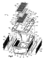
- Fig. 1 is a perspective view of an apparatus 10 constructed in accordance with the present invention.
- the apparatus 10 is a transport device for transporting at least one laboratory animal, such as a rodent.
- the apparatus 10 includes a container 12, a cover piece 14, and a closure piece 16.
- the container 12 includes a bottom wall 18, first and second end walls 20 and 22, respectively, first and second side walls 24 and 26, respectively, and an open top.
- a cavity 28 is defined within the container 12 in the space between the bottom wall 18 and the open top, between the first and second end walls 20 and 22, and between the first and second side walls 24 and 26.
- the cavity 28 houses at least one laboratory animal (not shown).
- the container 12 is constructed so that laboratory animals may only be inserted into and extracted from the cavity 28 through the open top.
- the bottom wall 18 of the container 12 is a generally rectangular, planar surface with rounded corners.
- a length of the bottom wall 18, indicated by L CB in Fig. 6 is approximately twice as long as a width of the bottom wall 18, indicated by W CB in Fig. 4 .
- the bottom wall 18 includes two long edges along its length L CB and two short edges along its width W CB .
- the bottom wall 18 may include multiple pairs of indexing projections 38, one of which is shown in Fig. 6 .
- Each pair of indexing projections 38 includes a first indexing projection 40 and a second indexing projection 42.
- the first indexing projection 40 is spaced from the second indexing projection 42 so that a slot 44 is formed between them.
- the slot 44 extends perpendicular to the long edges of the bottom wall 18.
- the first end wall 20 of the container 12 extends upwardly from the bottom wall 18.
- the first end wall is trapezoidal and has parallel lower and upper edges 46 and 48 ( Fig. 6 ), respectively and angled side edges 50 ( Fig. 1 ).
- the upper edge 48 of the first end wall 20 is longer than the lower edge 46 of the first end wall.
- the lower edge 46 of the first end wall 20 has a length that is approximately equal to the width W CB of the bottom wall 18.
- a rounded edge 52 ( Fig. 6 ) connects the lower edge 46 of the first end wall 20 with an associated one of the short edges of the bottom wall 18.
- the first end wall 20 extends at an angle of greater than ninety degrees relative to the bottom wall 18 such that the upper edge 48 of the first end wall extends outwardly beyond the associated short edge of the bottom wall 18.
- the second end wall 22 of the container 12 is similar to the first end wall 20.
- the second end wall 22 also extends upwardly from the bottom wall 18.
- the second end wall 22 is trapezoidal and has parallel lower and upper edges 54 and 56 ( Fig. 6 ), respectively, and angled side edges (not shown).
- the upper edge 56 of the second end wall 22 is longer than the lower edge 54 of the second end wall.
- the lower edge 54 of the second end wall 22 has a length that is approximately equal to the width W CB of the bottom wall 18.
- a rounded edge 58 ( Fig. 6 ) connects the lower edge 54 of the second end wall 22 with the other short edge of the bottom wall 18.
- the second end wall 22 extends at an angle of greater than ninety degrees relative to the bottom wall 18 such that the upper edge 56 of the second end wall extends outwardly beyond the other short edge of the bottom wall.
- the first side wall 24 of the container 12 also extends upwardly from the bottom wall 18.
- the first side wall 24 has a trapezoidal shape and includes parallel lower and upper edges 60 and 62 ( Fig. 4 ), respectively, and angled first and second side edges (not shown).
- the upper edge 62 of the first side wall 24 is longer than the lower edge 60 of the first side wall.
- the lower edge 60 of the first side wall 24 has a length that is approximately equal to the length L CB of the bottom wall 18.
- a rounded edge 64 ( Fig. 4 ) connects the lower edge 60 of the first side wall 24 with an associated one of the long edges of the bottom wall 18.
- the first side wall 24 extends at an angle of greater than ninety degrees relative to the bottom wall 18 such that the upper edge 62 of the first side wall extends outwardly beyond the associated long edge of the bottom wall.
- the first side wall 24 also includes inner and outer surfaces 66 and 68 ( Fig. 4 ), respectively.
- the inner and outer surfaces 66 and 68 are planar and extend parallel to one another.
- a plurality of air passages 70 extends through the first side wall 24 from the inner surface 66 to the outer surface 68.
- the air passages 70 allow air flow into and out of the cavity 28 of the container 12.
- each air passage 70 is preferably square with preferred dimensions of three millimeters by three millimeters. Preferably, two millimeters separate each air passage 70 from each adjacent air passage 70.
- the plurality of air passages 70 form three separate arrays 72, 74, and 76.
- An inner array 72 of air passages 70 is centered between the lower and upper edges 60 and 62 of the first side wall 24 and extends over approximately seventy-five percent of the distance between the lower and upper edges of the first side wall.
- the inner array 72 is also centered between the first and second side edges of the first side wall 24.
- the inner array 72 extends over a distance of approximately forty percent of the length of the lower edge 60 of the first side wall 24.
- a first outer array 74 is located between the inner array 72 and the first side edge of the first side wall 24.
- a second outer array 76 is located between the inner array 72 and the second side edge of the first side wall 24.
- Both the first and second outer arrays 74 and 76 extend between the lower and upper edges 60 and 62 of the first side wall 24 a distance equal to that of the inner array 72.
- a length of each of the first and second outer arrays 74 and 76 along the lower edge 60 of the first side wall 24 is approximately one-half the length of the inner array 72.
- the first side wall 24 also includes two vertical ribs, a second of which is shown at 78 in Fig. 6 .
- a first of the two vertical ribs separates the inner array 72 from the first outer array 74.
- the second 78 of the two vertical ribs separates the inner array 72 from the second outer array 76.
- a frame 80 protrudes outwardly from the outer surface 68 of the first side wall 24 and surrounds the arrays 72, 74, and 76 of air passages 70.
- the first side wall 24 of the container 12 also includes two locking projections (not shown).
- a first locking projection is located adjacent the frame 80 near the first side edge of the first side wall 24.
- a second locking projection is located adjacent the frame 80 near the second side edge of the first side wall 24.
- the locking projections are centered relative to the frame 80.
- Each locking projection includes a locking portion (not shown) for interlocking with cooperating locking projections.
- the first side wall 24 also includes two nesting protrusions, one of which is shown at 82 in Fig. 4 .
- a first nesting protrusion is located adjacent the frame 80 near the first side edge of the first side wall 24.
- the first nesting protrusion extends from the first locking projection to the upper edge 62 of the first side wall 24 and extends outwardly of the outer surface 68 of the first side wall.
- a vertically extending outer face defines the outermost surface of the first nesting protrusion.
- a second nesting protrusion 82 is located adjacent the frame 80 near the second side edge of the first side wall 24.
- the second stacking protrusion 82 extends from the second locking projection to the upper edge 62 of the first side wall 24 and extends outwardly of the outer surface 68 of the first side wall.
- a vertically extending outer face 84 ( Fig. 4 ) defines the outermost surface of the second nesting protrusion 82.
- a plurality of holes may extend into the first and second nesting protrusions from the outer face of each nesting protrusion. The plurality of holes saves material when the nesting protrusions are molded.
- the second side wall 26 of the container 12 is similar to the first side wall 24.
- the second side wall 26 also extends upwardly from the bottom wall 18.
- the second side wall 26 has a trapezoidal shape and includes parallel lower and upper edges 86 and 88 ( Fig. 4 ), respectively, and angled first and second side edges, the second of which is shown at 90 in Fig. 6 .
- the upper edge 88 of the second side wall 26 is equal in length to the upper edge 62 of the first side wall 24 and the lower edge 86 of the second side wall is equal in length to the lower edge 60 of the first side wall.
- a rounded edge 92 ( Fig. 4 ) connects the lower edge 86 of the second side wall 26 with an associated one of the long edges of the bottom wall 18.
- the second side wall 26 extends at an angle of greater than ninety degrees relative to the bottom wall 18 such that the upper edge 88 of the second side wall extends outwardly beyond the associated long edge of the bottom wall.
- the second side wall 26 also includes inner and outer surfaces 94 and 96 ( Fig. 4 ), respectively.
- the inner and outer surfaces 94 and 96 are planar and extend parallel to one another.
- a plurality of air passages 98 extends through the second side wall 26 from the inner surface 94 to the outer surface 96.
- the air passages 98 allow air flow into and out of the cavity 28 of the container 12.
- each air passage 98 is square with preferred dimensions of three millimeters by three millimeters. Preferably, two millimeters separate each air passage 98 from each adjacent air passage 98.
- the plurality of air passages 98 form three separate arrays 100, 102 and 104.
- the second side wall 26 includes an inner array 100 and first and second outer arrays 102 and 104, respectively, of air passages 98.
- the inner array 100 on the second side wall 26 has the same size and a corresponding location to the inner array 72 on the first side wall 24.
- the first and second outer arrays 102 and 104 also have the same sizes and corresponding locations to the first and second arrays 74 and 76 on the first side wall 24.
- the second side wall 26 also includes two vertical ribs, one of which is shown at 106 in Fig. 6 .
- a first of the two vertical ribs separates the inner array 100 from the first outer array 102.
- a second 106 of the two vertical ribs separates the inner array 100 from the second outer array 104.
- a frame 108 protrudes from the outer surface 96 of the second side wall 26 and surrounds the arrays 100, 102, and 104 of air passages 98.
- the second side wall 26 of the container 12 also includes two locking projections, a second of which is shown at 110 in Fig. 6 .
- a first locking projection is located adjacent the frame 108 near the first side edge of the second side wall 26.
- a second locking projection 110 is located adjacent the frame 108 near the second side edge 90 of the second side wall 26.
- the locking projections are centered relative to the frame 108.
- Each locking projection includes a locking portion (not shown) for interlocking with cooperating locking projections.
- the second side wall 26 also includes first and second nesting protrusions 112 and 114 ( Fig. 1 ), respectively.
- the first and second nesting protrusions 112 and 114 on the second side wall 26 correspond in size and location to the first and second nesting protrusions 82 of the first side wall 24.
- Vertically extending outer faces define outermost surfaces of the first and second nesting protrusions 112 and 114.
- Figs. 4 and 6 illustrate the outer face 116 of the second nesting protrusion 114.
- a plurality of holes 118 four of which are shown in Fig. 6 , extend into the second nesting protrusion 114 from the outer face 116. The holes 118 save material when the nesting protrusion 114 is molded.
- a rim 120 ( Fig. 2 ) extends around the upper edges 48, 56, 62 and 88 of the first and second end walls 20 and 22 and the first and second side walls 24 and 26.
- the rim 120 is generally rectangular and defines the open top of the container 12.
- the rim 120 includes an inner wall 122 and an outer wall 124.
- the inner wall 122 of the rim 120 extends upwardly from the end walls 20 and 22 and the side walls 24 and 26.
- the outer wall 124 of the rim 120 extends parallel to the inner wall 122 and is located outwardly of the end walls 20 and 22 and the side walls 24 and 26.
- a lower wall 126 of the rim 120 connects the inner and outer walls 122 and 124.
- a series of small cavities 128 may be formed in the rim 120 between the inner and outer walls 122 and 124.
- the rim 120 may also include slots 130 ( Fig. 2 ) that extend through the inner wall 122 of the rim on the first and second side walls 24 and 26. The slots 130 align with and extend parallel to the slot 44 formed by the pair of indexing projections 38.
- the container 12 is preferably molded as one piece from a thermoplastic.
- a polypropylene having high flow characteristics and having high heat stability characteristics is used.
- the wall thickness of each wall of the container 12, including the bottom wall 18, the end walls 20 and 22, and the side walls 24 and 26, is approximately two millimeters.
- the open top of the container 12 is larger than the bottom wall 18 of the container.
- multiple containers 12 may be nested together by inserting the bottom wall 18 of a first container through the open top of a second container.
- the nesting protrusions 82, 112, and 114 extending from the first and second side walls 24 and 26 of the first container rest on the rim 120 of the second container and prevent the first and second containers from wedging together.
- the nesting protrusions 82, 112, and 114 also space the bottom wall 18 of the first container away from the bottom wall 18 of the second container so that multiple containers 12 may be sterilized, preferably in an autoclave, while nested.
- the cover piece 14 has a generally rectangular upper wall 132 with rounded corners.
- the upper wall 132 of the cover piece 14 is flat and is sized to cover the open top of the container 12.
- the upper wall 132 includes first and second end edges 134 and 136, respectively, and first and second side edges 138 and 140, respectively.
- the first and second end edges 134 and 136 have a width that is approximately equal to the distance between the outer walls 124 of the rim 120 adjacent the first and second side walls 24 and 26 of the container 12.
- the first and second side edges 138 and 140 of the upper wall 132 of the cover piece 14 have a length that is approximately equal to the distance between the outer walls 124 of the rim 120 adjacent the first and second end walls 20 and 22 of the container 12.
- a rim 142 extends around an outer periphery of the cover piece 14. As shown in Figs. 4 and 5 , the rim 142 includes a leg 144 that curves away from the upper wall 132 to extend generally perpendicular to the upper wall. A flange 146 extends inwardly from the leg 144 in a direction parallel to and toward the upper wall 132 of the cover piece 14. An outer surface of the leg 144 defines an outer surface 150 ( Fig. 3 ) of the rim 142.
- each mating protrusion 154 includes first and second projections 156 and 158, respectively.
- the first projection 156 of each mating protrusion 154 extends outwardly of the outer surface 150 of the rim 142 by a first distance.
- the second projection 158 of the mating protrusion 154 includes a stepped outer surface 160.
- the stepped outer surface 160 has a first portion 162 that extends outwardly of the outer surface 150 of the rim 142 by a second distance, which is greater than the first distance.
- the stepped outer surface 160 of the second projection 158 also has a second portion 164, on an opposite side of the first portion 162 from the first projection 156 of the mating protrusion 154, which extends outwardly of the outer surface 150 of the rim 142 by the first distance.
- a space 166 separates the second projection 158 of the mating protrusion 154 from the first projection 156.
- the cover piece 14 illustrated in Fig. 3 includes six mating protrusions 154.
- the portion of the rim 142 adjacent each of the first and second side edges 138 and 140 of the upper wall 132 of the cover piece 14 includes two mating protrusions 154 and the portion of the rim 142 adjacent each of the first and second end edges 134 and 136 of the upper wall 132 of the cover piece 14 includes one mating protrusion 154.
- the upper wall 132 of the cover piece 14 also includes a centrally located and generally rectangular recess 168 ( Fig. 2 ).
- First and second recess side walls 170 and 172 ( Fig. 3 ), respectively, first and second recess end walls 174 and 176 ( Fig. 3 ), respectively, and a recess bottom wall 178 ( Fig. 4 ) define the recess 168.
- the recess 168 in the embodiment illustrated has a length of approximately seventy percent of the length of the upper wall 132 of the cover piece 14 and a width of approximately sixty percent of the width of the upper wall of the cover piece.
- the recess bottom wall 178 extends parallel to the upper wall 132 of the cover piece 14.
- the first and second recess end walls 174 and 176 and the first and second recess side walls 170 and 172 connect the recess bottom wall 178 to the upper wall 132 of the cover piece 14.
- the first recess side wall 170 includes an outwardly extending arcuate groove 180 ( Figs. 4 and 5 ) in a location equidistant from the first and second recess end walls 174 and 176.
- An arcuate extension 182 ( Fig. 5 ) of the recess bottom wall 178 extends into the arcuate groove 180.
- a first cutout 184 ( Fig.
- first recess end wall 174 extends into the first recess end wall 174 and a second cutout 186 ( Fig. 3 ) extends into the second recess end wall 176 in a location corresponding to the first cutout.
- the recess bottom wall 178 extends into the first and second recess cutouts 184 and 186.
- the recess bottom wall 178 includes rectangular passage 188 ( Figs. 2 and 5 ).
- the rectangular passage 188 has a length of approximately ninety percent of the distance between the first and second recess end walls 174 and 176 and a width of approximately sixty-five percent of the distance between the first and second recess side walls 170 and 172.
- the passage 188 is centrally located between the first and second recess end walls 174 and 176 near the first recess side wall 170.
- the recess bottom wall 178 also includes first and second viewing apertures 190 and 192 ( Fig. 2 ), respectively.
- the first and second viewing apertures 190 and 192 align lengthwise with one another and are located near the second recess side wall 172.
- the first viewing aperture 190 is located nearer the first recess end wall 174 and the second viewing aperture 192 is located nearer the second recess end wall 176.
- the recess bottom wall 178 also includes aligning pins 194 ( Fig. 3 ).
- the aligning pins 194 project upwardly from the recess bottom wall 178.
- Fig. 3 shows the recess bottom wall 178 having three aligning pins 194, one located between the first recess end wall 174 and the first viewing aperture 190, one located between the first and second viewing apertures 190 and 192, and one located between the second viewing aperture 192 and the second recess end wall 176.
- the upper wall 132 of the cover piece 14 also includes four stacking protrusions 196, as shown in Fig. 3 .
- Each stacking protrusions 196 is located near a rounded corner of the upper wall 132 of the cover piece 14.
- each rounded corner of the upper wall 132 of the cover piece 14 has an associated stacking protrusion 196.
- each stacking protrusions 196 includes an arcuate outer wall 197 that extends upwardly from the upper surface 132 of the cover piece 14.
- the arcuate outer wall 197 tapers inwardly, toward the recess 168 of the cover piece 14, as it extends upwardly from the upper wall 132, as shown in Fig. 4 .
- the arcuate outer wall 197 terminates at an arcuate upper wall 198 ( Fig. 3 ).
- the arcuate upper wall 198 extends approximately parallel to the upper wall 132 of the cover piece 14.
- Each stacking protrusion 196 also includes an arcuate inner wall 199 that extends upwardly from the upper wall 132 of the cover piece 14 approximately half the distance of the arcuate outer wall 197.
- the arcuate inner wall 199 tapers outwardly, away from the recess 168 in the cover piece 14, as it extends upwardly from the upper wall 132 of the cover piece 14.
- a horizontal support wall 200 ( Fig. 3 ) extends outwardly from the arcuate inner wall 199 toward the arcuate outer wall 197 in a direction generally parallel to the upper wall 132 of the cover piece 14.
- a vertical support wall 201 ( Fig. 4 ) connects the horizontal support wall 200 with the arcuate upper wall 198 of each stacking protrusion 196.
- Each stacking protrusion 196 is open from an underside of the cover piece 14.
- the four stacking protrusions 196 form pockets (not shown) on the underside of the cover piece 14.
- the pockets formed by the stacking protrusions 196 allow multiple cover pieces to be nested together.
- the stacking protrusions 196 from one cover piece 14 are received in the pockets formed by the stacking protrusions of another cover piece.
- the ability of the cover piece 14 to nest allows multiple cover pieces to be sterilized at once, preferably, while nested.
- the cover piece 14 is molded from a thermoplastic, preferably polypropylene. Preferably, the walls of the cover piece 14 are approximately two millimeters thick.
- a plurality of tabs 204 extends outwardly of the recess end walls 174 and 176 and side walls 170 and 172 into the recess 168.
- Each of the first and second recess end walls 174 and 176 and the second recess side wall 172 includes three tabs 204.
- Each tab 204 is spaced from the other tabs 204.
- the first recess side wall 170 includes two tabs 204, spaced from one another.
- the closure piece 16 is rectangular and is sized to be received in the recess 168 in the cover piece 14 and to be secured within the recess by the tabs 204.
- the closure piece 16 includes an upper wall 206 having lower and upper surfaces 208 ( Fig. 4 ) and 210, respectively.
- the upper wall 206 also includes first and.second side edges 212 and 214, respectively, and first and second end edges 216 and 218, respectively.
- a handle 220 is located on the first side edge 212 of the closure piece 16 equidistance from the first and second end edges 216 and 218. As shown in Fig. 5 , the handle 220 projects upwardly from the upper surface 210 of the upper wall 206 and slightly outwardly of the first side edge 212.
- the upper wall 206 of the closure piece 16 also includes a hinge 222 that extends from the first end edge 216 to the second end edge 218 of the closure piece 16. As shown in Fig. 4 , the hinge 222 is located on the lower surface 208 of the upper wall 206 and is a line where the upper wall 206 has a reduced thickness. The hinge 222 is located inward of the second side edge 214 of the upper wall 206 a distance of approximately twenty five percent of a width of the upper wall; i.e., the width of the upper wall 206 is the distance between the first and second side edges 212 and 214 of the upper wall. Thus, approximately seventy-five percent of the upper wall 206 extends between the hinge 222 and the handle 220 of the upper wall 206.
- the portion 224 of the upper wall 206 between the second side edge 214 and the hinge 222 includes three apertures 226 ( Fig. 3 ) and two windows 228 ( Fig. 3 ). Each one of the three apertures 226 is in a location corresponding to the location of an associated aligning pin 194 of the cover piece 14. Each of the three apertures 226 is sized for receiving an associated aligning pin 194.
- the two windows 228 are in locations corresponding to the viewing apertures 190 and 192 of the cover piece 14.
- the two windows 228 are formed from reduced thickness portions of the upper wall 206, as is shown in Fig. 4 .
- the area of the two windows 228 is transparent.
- the upper wall 206 of the closure piece 16 also includes first and second locking projections, a first 230 of which is shown in Fig. 2 .
- the first locking projection 230 is located adjacent the first end edge 216 of the upper wall 206 in a position to be received by the first cutout 184 in the cover piece 14.
- the second locking projection is located adjacent the second end edge 218 of the upper wall 206 in a position to be received by the second cutout 186 in the cover piece 14.
- Each locking projection includes a locking portion for interlocking with cooperating locking projections.
- a rectangular recess 232 extends into the upper wall 206 of the closure piece 16.
- the recess 232 is centrally located in the portion 234 of the upper wall 206 between the hinge 222 and the handle 220.
- the recess 232 has a length of approximately ninety percent of the length of the upper wall 206; i.e., the length of the upper wall 206 is the distance between the first and second end edges 216 and 218 of the upper wall.
- a recess bottom wall 236 extends parallel to the upper wall 206 and includes upper and lower surfaces (not indicated in the Figures). As shown in Fig. 5 , the upper surface of the recess bottom wall 236 aligns with the lower surface 208 of the upper wall 206 of the closure piece 16.
- a plurality of air passages 238 extends through the recess bottom wall 236 from the upper surface to the lower surface.
- Each of the plurality of air passages 238 is square and has dimensions of three millimeters by three millimeters. Approximately two millimeters separates each air passage 238 from each adjacent air passage 238.
- the plurality of air passages 238 forms three separate arrays 240, 242 and 244 ( Fig. 2 ).
- An inner array 240 of air passages 238 is centered within the recess 232 and extends over approximately forty percent of the length of the recess and approximately ninety percent of the width of the recess.
- a first outer array 242 is located in the recess bottom wall 236 on one side of the inner array 240 and a second outer array 244 is located in the recess bottom wall 236 on the opposite side of the inner array 240 from the first outer array 242.
- the first and second outer arrays 242 and 244 have widths that equal the width of the inner array 240 and lengths that are approximately one-half the length of the inner array 240.
- the recess bottom wall 236 also includes first and second ribs 246 ( Fig. 2 ).
- the first rib 246 separates the inner array 240 from the first outer array 242.
- the second rib 246 separates the inner array 240 from the second outer array 244.
- a frame 248 protrudes from the lower surface 208 of the upper wall 206 of the closure piece 16.
- the frame 248 surrounds the arrays of air passages 238.
- the closure piece 16 is molded from a thermoplastic, preferably polypropylene.
- the walls of the closure piece 16 are approximately two millimeters thick.
- the thickness of the upper wall 206 of the closure piece 16 in the location of the windows 228 is approximately one millimeter thick.
- the apparatus 10 also includes three air filters 250, 252, and 254. Each air filter is formed from a spun polypropylene blend.
- a first air filter 252 is sized to be received in the frame 80 of the first side wall 24 of the container 12 and to overlie the air passages 70 within the first side wall.
- a second air filter 252 is sized to be received in the frame 108 of the second side wall 26 of the container 12 and to overlie the air passages 98 within the second side wall.
- the third air filter 254 is sized to be received in the recess 232 of the closure piece 16 and to overlie the air passages 238 within the recess bottom wall 236.
- the apparatus 10 also include three filter guards 256, 258, and 260.
- Each filter guard is rectangular and includes and inner and an outer surface.
- a plurality of air passages 262 extends through each filter guard 256, 258, and 260.
- Each filter guard also includes two locking projections. One locking projection is centered on each short edge of the rectangular filter guard.
- Each locking projection includes a locking portion for interlocking with cooperating locking projections.
- a first filter guard 256 is sized to overlie the frame 80 of the first side wall 24 of the container 12 such that the locking projections of the first filter guard 256 interlock with the locking projections of the first side wall 24.
- the plurality of air passages 262 in the first filter guard 256 are sized and arranged to correspond with the plurality of air passages 70 in the first side wall 24.
- a second filter guard 258 is sized to overlie the frame 108 of the second side wall 26 of the container 12 such that the locking projections of the second filter guard 258 interlock with the locking projections 110 of the second side wall 26.
- the plurality of air passages 262 in the second filter guard 258 are sized and arranged to correspond with the plurality of air passages 98 in the second side wall 26.
- a third filter guard 260 is sized to overlie the recess 232 of the closure piece 16 such that the locking projections of the third filter guard 260 interlock with the locking projections 230 of the upper wall 206 of the closure piece 16.
- the plurality of air passages 262 in the third filter guard 260 are sized and arranged to correspond with the plurality of air passages 238 in the recess bottom wall 236 of the closure piece 16.
- the apparatus 10 may also include one or more dividers 264.
- Each divider 264 is received in the container 12 to divide the cavity 28 into compartments.
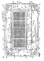
- Fig. 6 illustrates one divider 264 that is received in the container 12 and that divides the cavity into first and second compartments 266 and 268, respectively.
- the divider 264 has a generally trapezoidal shape and includes parallel lower and upper edges and angled first and second side edges.
- the divider 264 is sized to extend snugly between the first and second side walls 24 and 26 of the container 12 and to extend from the bottom wall 18 to the open top of the container 12.
- the upper edge of the divider 264 includes cutouts that receive portions of the cover piece 14 and the closure piece 16.
- the divider 264 also includes two extensions 270.
- a first extension 270 extends outwardly of the first side edge of the divider 264 adjacent an upper edge of the divider.
- the second extension 270 extends outwardly of the second side edge of the divider 264 adjacent the upper edge of the
- the first and second filters 250 and 252 are heat welded over the air passages 70 and 98 in the container 12.
- the first filter 250 becomes fixedly attached to the portion of the first side wall 24 between the frame 80 and the arrays 72, 74, and 76 of air passages 70.
- the first filter 250 also becomes fixedly attached to the vertical ribs 78 that separate the arrays of air passages 70.
- the second filter 252 becomes fixedly attached to the portion of the second side wall 26 between the frame 108 and the arrays 100, 102, and 104 of air passages 98.
- the second filter 252 also becomes fixedly attached to the vertical ribs 106 that separate the arrays of air passages 98.
- first and second filter guards 256 and 258 are attached to the container 12.
- An outer periphery of the first filter guard 256 lies against the frame 80 of the first side wall 24 of the container 12 and the locking projections of the first filter guard 256 interlock with the locking projections of the first side wall 24.
- the second filter guard 258 lies against the frame 108 of the second side wall 26 of the container 12 and the locking projections of the second filter guard 258 interlock with the locking projections 110 of the second side wall 26.
- the first and second filter guards 256 and 258 protect the first and second filters 250 and 252, respectively, from animals located outside of the container 12.
- the divider 264 if use of a divider is desired, is placed in the cavity 28 of the container 12.
- a lower edge of the divider 264 is received in the slot 44 formed by the pair of indexing projections 38 on the bottom wall 18 of the container 12.
- the first and second extensions 270 of the divider 264 are received in the slots 130 formed in the rim 120 of the container 12.
- the pair of indexing projections 38 and the rim 120 prevent movement of the divider 264 relative to the container 12 when the divider is received in the associated slots 44 and 130.
- the third filter 254 is then heat welded in the recess 232 of the closure piece 16.
- the third filter 254 becomes fixedly attached to the periphery of the recess bottom wall 236 and to the ribs 246 that separate the arrays 240, 242, and 244 of air passages 238 in the closure piece 16.
- each aperture 226 in the closure piece 16 receives an associated aligning pin 194 of the cover piece 14.
- the closure piece 16 is then forced downwardly into the recess 168 of the cover piece 14.
- the tabs 204 on the cover piece 14 deform and then snap over the upper surface 210 of the upper wall 206 of the closure piece 16. As a result, the tabs 204 secure the closure piece 16 relative to the cover piece 14.
- the windows 228 of the closure piece 16 overlie the viewing apertures 190 and 192 of the cover piece 14 and allow sight into the cavity 28 of container 12.
- the handle 220 of the closure piece 16 is located in the arcuate groove 180 of the cover piece 14. The arcuate groove 180 provides access to the handle 220. It should be noted that when the closure piece 16 is properly secured relative to the cover piece 14, a seal is formed between the lower surface 208 of the upper wall 206 of the closure piece 16 and the recess bottom wall 178 of the cover piece 14. This seal prevents airflow between the cover piece 14 and the closure piece 16.
- the third filter guard 260 is secured over the third filter 254.
- the third filter guard 260 overlies the recess 232 of the closure piece 16.
- the locking projections of the third filter guard interlock with the locking projections 230 of the upper wall 206 of the closure piece 16 to secure the third filter guard 260 relative to the closure piece 16.
- the third filter guard 260 protects the third filter 254 from animals located outside of the apparatus 10.
- the cover piece 14 is then attached to the rim 120 of the container 12.
- the cover piece 14 is pressed onto the container 12 such that the flange 146 of the leg 144 of the rim 142 of the cover piece 14 snaps around and locks under lower wall 126 of the rim 120 of the container 12.
- the apparatus 10 of the present invention is used for transporting laboratory animals.
- a bedding typically a sawdust bedding 272 as shown in Fig. 6
- a food and water source is also provided in each compartment 266 and 268.
- one or more laboratory animal may be inserted into or extracted from the apparatus 10.
- the laboratory animals pass through the passage 188 of the cover piece 14 and into one of the compartments 266 and 268 within the cavity 28 of the container 12 of the apparatus 10.
- the rotatable portion 234 of the closure piece 16 is rotated back to the closed position. During the transition between the open and closed positions, the portion 234 of the closure piece 16 snaps over the tabs 204 in the cover piece 14. The tabs 204 in the cover piece 14 secure the rotatable portion 234 of the closure piece 16 in the closed position.
- a plurality of laboratory animals may be transported in one apparatus 10.
- the divider 264 may be used to compartmentalize the cavity within the container 12 to segregate laboratory animals from one another.
- sight is provided into each compartment 266 and 268 through one of the windows 228 in the closure piece 16 and the associated viewing aperture 190 and 192 of the cover piece 14.
- Airflow into and out of the apparatus 10 is provided through the plurality of air passages 70, 98, and 238 in the side walls 24 and 26 of the container 12 and in the closure piece 16. Since filters 250, 252, and 254 cover all of the air passages 70, 98, and 238, airflow into the cavity 28 is filtered of contaminants.
- the apparatus 10 of the present invention has been designed to cooperate with similar apparatuses for the transport of large numbers of laboratory animals using multiple apparatuses.
- the apparatus 10 includes features that enable the apparatus 10 to be placed in a stacked relationship, in a side-by-side relationship, and in an end-by-end relationship with other similar apparatuses.
- the stacking protrusions 196 of the cover piece 14 are arranged so as to be capable of receiving the bottom wall 18 of the container 12.
- the stacking protrusions 196 of a first apparatus 10A may be used to support a second apparatus 10B.
- the bottom wall 18 of the second apparatus 10B rests on the horizontal support wall 200 of the stacking protrusions 196 of the first apparatus 10A.
- the bottom wall 18 of the container 12 of the second apparatus 10B is spaced from the upper wall of the cover piece 14 of the first apparatus 10A.
- the vertical support walls 201 of the stacking protrusions 196 of the first apparatus 10A prevent movement of the second apparatus 10B in a horizontal direction, i.e., parallel to the bottom wall 18 of the second apparatus 10B.
- the mating protrusions 154 on the rim 142 of the cover piece 14 of the apparatus 10 may be interlocked with corresponding mating protrusions 154 of an adjacent apparatus 10.
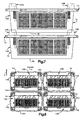
- a top view of four apparatuses 10A, 10B, 10C, and 10D is shown.
- the apparatuses 10A-D are connected both side-by-side and end-by-end.
- the mating protrusions 154 of each cover piece 14 interlock with the mating protrusions 154 of an adjacent cover piece 14.
- a mating protrusion 154 of apparatus 10B prevents apparatus 10A from moving in the direction indicated by arrow X.
- Two mating protrusions 154 of apparatus 10C prevent apparatus 10A from moving in the direction indicated by arrow Y. It should be noted that when positioned side-by-side and end-by-end, the side walls of the containers of the adjacent apparatuses are separated from one another for enabling airflow into and out of the cavity of each apparatus through the side walls of the container of the apparatus.
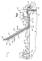
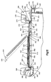
- Fig. 9 is a perspective view of an apparatus 10' constructed in accordance with a second embodiment of the present invention.
- the apparatus 10' is a transport device for transporting at least one laboratory animal, such as a rodent.
- the apparatus 10' includes a container 12, a cover piece 302, and a closure piece 304.
- the container 12 of the apparatus 10' of the second embodiment of the present invention has an identical construction as the container 12 illustrated and discussed with regard to Figs. 1-6 . Therefore, the specific structures of the container 12 will not be discussed in detail with regard to apparatus 10' and the same reference numbers as were used in Figs. 1-6 are used for identifying the structures of the container 12 of apparatus 10'.
- the cover piece 302 of apparatus 10' has a generally rectangular upper wall 306 with rounded corners.
- the upper wall 306 of the cover piece 302 is flat and is sized to cover the open top of the container 12.
- the upper wall 306 includes first and second end edges 308 and 310, respectively, and first and second side edges 312 and 314, respectively.
- a rim 316 extends around an outer periphery of the cover piece 302. As shown in Fig. 12 , the rim 316 includes a leg 318 that curves away from the upper wall 306 to extend generally perpendicular to the upper wall. A flange 320 extends inwardly from the leg 318 in a direction parallel to and toward the upper wall 306 of the cover piece 302. An outer surface of the leg 318 defines an outer surface 322 ( Fig. 11 ) of the rim 316.
- a plurality of mating protrusions 324 extends outwardly from the outer surface of the rim 316. As illustrated with reference to one mating projection in Fig. 11 , each mating protrusion 324 includes first and second projections 326 and 328, respectively. The first projection 326 of each mating protrusion 324 extends outwardly of the outer surface of the rim 316 by a first distance. The second projection 328 of the mating protrusion 324 includes a stepped outer surface 330. The stepped outer surface 330 has a first portion 332 that extends outwardly of the outer surface 322 of the rim 316 by a second distance, which is greater than the first distance.
- the stepped outer surface 330 of the second projection 328 also has a second portion 334, on an opposite side of the first portion 332 from the first projection 326 of the mating protrusion 324, which extends outwardly of the outer surface 322 of the rim 316 by the first distance.
- a space 336 separates the second projection 328 of the mating protrusion 324 from the first projection 326.
- the cover piece 302 illustrated in Fig. 11 includes six mating protrusions 324.
- the portion of the rim 316 adjacent each of the first and second side edges 312 and 314 of the upper wall 306 of the cover piece 302 includes two mating protrusions 324 and the portion of the rim 316 adjacent each of the first and second end edges 308 and 310 of the upper wall 306 of the cover piece 302 includes one mating protrusion 324.
- the upper wall 306 of the cover piece 302 also includes a centrally located and generally rectangular protuberance 338 ( Fig. 10 ).
- First and second protuberance side walls 340 and 342 ( Fig. 10 ), respectively, first and second protuberance end walls 344 and 346 ( Fig. 11 ), respectively, and a protuberance upper wall 348 ( Fig. 10 ) define the protuberance 338.
- the protuberance 338 of the cover piece 302 in the embodiment illustrated in Fig. 10 has a length of approximately seventy percent of the length of the upper wall 306 of the cover piece 302 and a width of approximately sixty percent of the width of the upper wall 306 of the cover piece 302.
- the protuberance upper wall 348 extends parallel to the upper wall 306 of the cover piece 302.
- the first and second protuberance end walls 344 and 346 and the first and second protuberance side walls 340 and 342 connect the protuberance upper wall 348 to the upper wall 306 of the cover piece 302.
- a plurality of tabs 350 extends outwardly each of the first and second protuberance end walls 344 and 346 and first and second protuberance side walls 342 and 344.
- the protuberance upper wall 348 includes a rectangular passage 352 ( Figs. 10 and 12 ).
- the rectangular passage 352 has a length of approximately ninety percent of the distance between the first and second protuberance end walls 344 and 346 and a width of approximately sixty-five percent of the distance between the first and second protuberance side walls 340 and 342.
- the passage 352 is centrally located between the first and second protuberance end walls 344 and 346 near the first protuberance side wall 340.
- the protuberance upper wall 348 also includes first and second viewing apertures 354 and 356 ( Fig. 10 ), respectively.
- the first and second viewing apertures 354 and 356 align lengthwise with one another and are located near the second protuberance side wall 342.
- the first viewing aperture 354 is located nearer the first protuberance end wall 344 and the second viewing aperture 356 is located nearer the second protuberance end wall 346.
- the protuberance upper wall 348 also includes three apertures 358 ( Fig. 10 ).
- a first aperture 358 is located between the first protuberance end wall 344 and the first viewing aperture 354.
- a second aperture 358 is located between the first and second viewing apertures 354 and 356 and a third aperture 358 is located between the second viewing aperture 356 and the second protuberance end wall 346.
- a recess 360 extends into the upper wall 306 of the cover piece 302 adjacent the first protuberance side wall 340.
- the recess 360 is located equidistance from the first and second protuberance end walls 344 and 346.
- the first protuberance side wall 340, an arcuate side wall 362, and a recess bottom wall 364 ( Fig. 12 ) define the recess 360.
- the upper wall 306 of the cover piece 302 also includes four stacking protrusions 366, as shown in Fig. 11 .
- Each stacking protrusions 366 is located near a rounded corner of the upper wall 306 of the cover piece 302.
- each rounded corner of the upper wall 306 of the cover piece 302 has an associated stacking protrusion 366.
- each stacking protrusion includes an arcuate outer wall 368 that extends upwardly from the upper surface 306 of the cover piece 302.
- the arcuate outer wall 368 tapers inwardly, toward the protuberance 338 of the cover piece 302, as it extends upwardly from the upper wall 306, as shown in Fig. 12 .
- the arcuate outer wall 368 terminates at an arcuate upper wall 370 ( Fig. 11 ).
- the arcuate upper wall 370 extends approximately parallel to the upper wall 306 of the cover piece 302.
- Each stacking protrusion 366 also includes an arcuate inner wall 372 that extends upwardly from the upper wall 306 of the cover piece 302 approximately half the distance of the arcuate outer wall 368.
- the arcuate inner wall 372 tapers outwardly, away from the protuberance 338 in the cover piece 302, as it extends upwardly from the upper wall 306 of the cover piece 302.
- a horizontal support wall 374 ( Fig. 11 ) extends outwardly from the arcuate inner wall 372 toward the arcuate outer wall 368 in a direction generally parallel to the upper wall 306 of the cover piece 302. As shown in Fig. 12 , the horizontal support wall 374 is located higher above the upper wall 306 of the cover piece 302 than the protuberance upper wall 348.
- a vertical support wall 376 ( Fig. 12 ) connects the horizontal support wall 374 with the arcuate upper wall 370 of each stacking protrusion 366.
- Each stacking protrusion 366 is open from an underside of the cover piece 302.
- the four stacking protrusions 366 form pockets (not shown) on the underside of the cover piece 302.
- the pockets formed by the stacking protrusions 366 allow multiple cover pieces to be nested together.
- the stacking protrusions 366 from one cover piece 302 are received in the pockets formed by the stacking protrusions 366 of another cover piece 302.
- the ability of the cover piece 302 to nest allows multiple cover pieces to be sterilized at once, preferably, while nested.
- the closure piece 304 is rectangular and is sized to overlie the protuberance 338 in the cover piece 302 and to be secured relative to the protuberance.
- the closure piece 304 includes an upper wall 382, first and second end walls 384 and 386, respectively, and first and second side walls 388 and 390, respectively.
- a length of the closure piece 304 is defined between the first and second end walls 384 and 386 and a width of the closure piece 304 is defined between the first and second side walls 388 and 390.
- the upper wall 382 of the closure piece 304 has lower and upper surfaces 392 and 394 ( Fig. 12 ), respectively.
- the upper wall 382 of the closure piece 302 also includes a hinge 396 that extends linearly across the length of the closure piece 304. As shown in Fig. 12 , the hinge 396 is formed on the lower surface 392 of the upper wall 382 and is defined by a reduced thickness of the upper wall 382.
- the hinge 396 is located inward of the second side wall 390 of the closure piece 304 a distance of approximately twenty five percent of the width of the closure piece 304. Thus, approximately seventy-five percent of the upper wall 382 extends between the hinge 396 and the first side wall 388 of the closure piece 304.
- a portion 398 of the upper wall 382 of the closure piece 304 between the second side wall 390 and the hinge 396 includes two windows 400 and 402 ( Fig. 11 ).
- the two windows 400 and 402 are formed from reduced thickness portions of the upper wall 382, as is shown in Fig. 12 .
- the area of the two windows 400 and 402 is transparent.
- the two windows 400 and 402 are in locations corresponding to the viewing apertures 354 and 356, respectively, of the cover piece 302.
- the portion 398 of the upper wall 382 also includes three aligning pins 404 ( Fig. 11 ). Each of the three aligning pins 404 extends downwardly from the lower surface 392 of the upper wall 382 in a location corresponding to the location of an aperture 358 of the cover piece 302. Each of the three aligning pins 404 is adapted to be received in an associated one of the apertures 358 of the cover piece 302.
- a portion 406 of the upper wall 382 of the closure piece 304 between the second side wall 390 and the hinge 396 includes a raised ridge 408 that extends upwardly from the upper wall 382.
- the raised ridge 408 outlines a centrally located area 410 of the portion 406 of the upper wall 382.
- the area 410 has a length of approximately ninety percent of the length of the upper wall 382.
- the area 410 includes a wall 412 that extends parallel to and is planar with the upper wall 382 of the closure piece 304.
- a plurality of air passages 414 extends through the wall 412.
- Each of the plurality of air passages 414 is square and has dimensions of three millimeters by three millimeters. Approximately two millimeters separates each air passage 414 from each adjacent air passage 414.
- the plurality of air passages 414 forms three separate arrays 416, 418, and 420 ( Fig. 10 ).
- An inner array 416 of air passages 414 is centered within the area 410 and extends over approximately forty percent of the length of the area 410 and approximately ninety percent of the width of the area 410.
- a first outer array 418 is located in the wall 412 on one side of the inner array 416 and a second outer array 420 is located in the wall 412 on the opposite side of the inner array 416 from the first outer array 418.
- the first and second outer arrays 418 and 420 have widths that equal the width of the inner array 416 and lengths that are approximately one-half the length of the inner array 416.
- the wall 412 includes first and second ribs 422 and 424 ( Fig. 10 ), respectively.
- the first rib 422 separates the inner array 416 from the first outer array 418.
- the second rib 424 separates the inner array 416 from the second outer array 420.
- the upper wall 382 of the closure piece 304 also includes first and second locking projections.
- the first locking projection 426 is shown in Fig. 10 and is centrally located on the upper wall 382 adjacent the first end wall 384 of the closure piece 304.
- the first locking projection 426 extends outwardly beyond the first end wall 384 of the closure piece 304.
- the second locking projection (not shown) is centrally located on the upper wall 382 adjacent the second end wall 386 of the closure piece 304.
- the second locking projection extends outwardly beyond the second end wall 386 of the closure piece 304.
- the first and second end walls 384 and 386 and the first and second side walls 388 and 390 of the closure piece 304 extend perpendicularly to the upper wall 382 of the closure piece 304. Opposite ends of the first and second end walls 384 and 386 and opposite ends of the first and second side walls 388 and 390 are curved so that each intersection of an end wall and a side wall is rounded to correspond with a rounded corner of the upper wall 382.
- Each of the first and second end walls 384 and 386 of the closure piece 304 includes an inner surface 384 ( Fig. 12 ) and an outer surface 430.
- a cutout 432 ( Fig. 9 ) extends through each of the first and the second end walls 384 and 386 in a location corresponding to the hinge 396 on the upper surface 382 of the closure piece 304. The cutouts 432 enable pivotal movement of portion 406 of the upper wall 382 about the hinge 396 and relative to portion 398 of the closure piece 304.
- the inner surface 328 of each of the first and second end walls 384 and 386 of the closure piece 304 includes a plurality of inwardly grooves.
- Fig. 12 illustrates one groove in the inner surface 428 of each of the first and second end walls 384 and 386. At least one groove is located on each side of the cutout 432 in each of the first and second end walls 384 and 386.
- Each groove of the plurality of grooves on the first and second end walls 384 and 386 is associated with a tab 350 in the first and second protuberance end walls 344 and 346 and is adapted to receive the associated tab 350 for securing the closure piece 304 relative to the cover piece 302.
- Each of the first and second side walls 388 and 390 of the closure piece 304 includes an inner surface and an outer surface.
- the inner surface of each of the first and second side walls 388 and 390 includes a plurality of grooves (not shown), which are similar to the grooves on the inner surface 428 of the first and second end walls 384 and 386.
- Each groove of the plurality of grooves in the first and second side walls 388 and 390 is associated with a tab 350 on the first and second protuberance side walls 340 and 342 and is adapted to receive the associated tab 350 for securing the closure piece 304 relative to the cover piece 302.
- a handle 434 extends outwardly from a lower edge of the first side wall 388 of the closure piece 304 at a location centrally located between the first and second end walls 384 and 386. When the closure piece 304 is secured to the cover piece 302, the handle 434 extends into the recess 360 of the cover piece 302 a spaced distance away from the recess bottom wall 364.
- the apparatus 10' also includes air filters and filter guards.
- the air filters and filter guards for the container 12 are identical to those discussed above with reference to Figs. 1-6 . Thus, the air filters and filter guards for the container 12 are not discussed in detail hereinafter.
- Air filter 440 is sized to be received in the area 410 outlined by the raised ridge 408 of the closure piece 304 and to overlie the air passages 414 that extend through wall 412.
- Filter guard 442 is sized to cover the area 410 of the closure piece 304 and to overlie raised ridge 408.
- the filter guard 442 includes first and second locking projections 444 and 446, respectively, each of which is adapted to interlock with an associated locking projection 426 of the closure piece 304 to secure the filter guard 442 relative to the closure piece 304 for covering the filter 440.
- Filter guard 442 also includes a plurality of air passages 448.
- the plurality of air passages 448 in the filter guard 442 are sized and arranged to correspond with the plurality of air passages 414 in the wall 412 of the closure piece 304.
- the container 12 of the apparatus 10' is assembled in the same manner as described above with reference to Figs. 1-6 . Thus, the assembly of the container 12 is not discussed below.
- the filter 440 is heat welded to the upper surface of the wall 412 in the area outlined by raised ridge 408 of the closure piece 304. When heat welded to the wall 412, the filter 440 becomes fixedly attached to the periphery of the wall 412 and to the ribs 422 and 424 that separate the arrays 416, 418, and 420 of air passages 414 in the closure piece 304.
- each aligning pin 404 of the closure piece 304 is received in an associated aperture 358 of the cover piece 302.
- the closure piece 304 is then forced downwardly until the grooves in the inner surfaces 428 of the first and second end walls 384 and 386 and the grooves in the inner surfaces of the first and second side walls 388 and 390 receive associated tabs 350 of the first and second end walls 344 and 346 and first and second side walls 340 and 342 of the protuberance 338.
- the closure piece 304 becomes secured to the cover piece 302.
- the windows 400 and 402 of the closure piece 304 overlie the viewing apertures 354 and 356 of the cover piece 302 and allow sight into the cavity 28 of container 12. Also, when the closure piece 304 is secured to the cover piece 302, the handle 434 of the closure piece 304 is located in the recess 360 of the cover piece 302.
- the end walls 384 and 386 and the side walls 388 and 390 of the closure piece 304 act as flashing and overlie associated end walls 344 and 346 and side walls 340 and 342 of the protuberance 338 of the cover piece 302 to form a seal between the closure piece 304 and the cover piece 302.
- the filter guard 442 is secured over the filter 440.
- the filter guard 442 overlies the raised ridge 408 of the closure piece 304 and the locking projections 444 and 446 of the filter guard 442 interlock with the locking projections 426 of the upper wall 382 of the closure piece 304.
- the filter guard 442 protects the filter 440 from animals located outside of the apparatus 10'.
- the cover piece 302 is then attached to the rim 120 of the container 12.
- the cover piece 302 is pressed onto the container 12 such that the flange 320 of the leg 318 of the rim 316 of the cover piece 302 snaps around and locks under lower wall 126 of the rim 120 of the container 12.
- portion 406 of the closure piece 304 between the handle 434 and the hinge 396 snaps away from the cover piece 302 and rotates from a closed position, shown in Fig. 12 by solid lines, to an open position, as shown in Fig. 12 by dashed lines.
- portion 398 of the closure piece 304 remains secured relative to the cover piece 302.
- one or more laboratory animal may be inserted into or extracted from the apparatus 10'.
- the laboratory animals pass through the passage 352 of the cover piece 302 and into one of the compartments 266 and 268 within the cavity 28 of the container 12 of the apparatus 10'.
- the rotatable portion 406 of the closure piece 304 is rotated back to the closed position. During the transition between the open and closed positions, the portion 406 of the closure piece 304 snaps onto the cover piece 302.
- a plurality of laboratory animals may be transported in one apparatus 10'.
- a divider may be used to compartmentalize the cavity 28 within the container 12 to segregate laboratory animals from one another.
- sight is provided into each compartment 266 and 268 of the container 12 through one of the windows 400 and 402 in the closure piece 304 and the associated viewing aperture 354 and 356 of the cover piece 302.
- Airflow into and out of the apparatus 10' is provided through the plurality of air passages 70 and 98 in the side walls 24 and 26 of the container 12 and the air passages 414 in the closure piece 304. Since filters 250, 252, and 440 cover all of the air passages 70, 98, and 414, airflow into the cavity 28 is filtered of contaminants.
- the apparatus 10' has been designed to cooperate with similar apparatuses for the transport of large numbers of laboratory animals using multiple apparatuses.
- the apparatus 10' includes features that enable the apparatus 10' to be placed in a stacked relationship, in a side-by-side relationship, and in an end-by-end relationship with other similar apparatuses.
- the stacking protrusions 366 of the cover piece 302 are arranged so as to be capable of receiving the bottom wall 18 of the container 12.
- the stacking protrusions 366 of a first apparatus 10A' may be used to support a second apparatus 10B'.
- the bottom wall 18 of the second apparatus 10B' rests on the horizontal support wall 374 of the stacking protrusions 366 of the first apparatus 10A'.
- the bottom wall 18 of the container 12 of the second apparatus 10B is spaced from the upper wall 382 of the closure piece 304 of the first apparatus 10A'.
- apparatus 10' may be placed in side-by-side or end-by-end connection with adjacent apparatuses in the same manner as discussed above with reference to Fig. 8 .
- the side walls of the containers 12 of the adjacent apparatuses are separated from one another for enabling airflow into and out of the cavity 28 of each apparatus through the side walls of the container 12 of the apparatus.
Description
- The present invention relates to an apparatus for transporting animals. Particularly, the present invention relates to an apparatus for transporting laboratory animals such as rodents.
- It may be desirable to transport laboratory animals between various laboratory facilities. Many times, it is desirable to transport the laboratory animals in a sterile environment. Some known apparatuses for transporting laboratory animals are formed from sterile cardboard. These cardboard apparatuses generally cannot withstand a second sterilization process and thus, cannot be reused. An apparatus for transporting laboratory animals that may be reused is desirable. Such apparatus must be durable enough to withstand periodic sterilization.
- Furthermore, the various laboratory facilities between which the laboratory animals are transported may be located in different nations. Thus, the apparatus housing the laboratory animals may be inspected when passing through customs of the different nations. Such inspection generally includes the interior of the apparatus. Contact between customs officials and the laboratory animals may not be desirable. Therefore, a need exists for an apparatus that allows inspection of the interior without opening of the apparatus.
- Attention is drawn to
US5349924A which discloses an animal kennel and more particularly a dog kennel of a type which can be transported in beds of trucks. The animal kennel comprises a removable partition which is inserted into a housing through a partition slot in a rear housing sidewall. A removable drop-in tray can be inserted by opening a top door of the kennel for locking the removable partition in position. - In accordance with the present invention an apparatus for transporting laboratory animals is provided as claimed in claim 1. Preferred embodiments of the invention are disclosed in the dependent claims.
- The present invention relates to an apparatus for transporting laboratory animals. The apparatus comprises a container, a cover piece, and a closure piece. The container defines a cavity for housing at least one laboratory animal. The container has an open top. The cover piece is connectable with the container for closing the open top of the container. The cover piece has a passage through which the at least one laboratory animal passes during insertion into and extraction from the cavity. The closure piece is associated with the cover piece and includes a portion that is rotatable relative to the cover piece between a first position in which the portion of the closure piece closes the passage in the cover piece to retain the at least one laboratory animal within the cavity and a second position in which the passage in the cover piece is open to permit the insertion and extraction of the at least one laboratory animal through the passage. The closure piece also includes a plurality of air passages that permit airflow into and out of the cavity. Filter material covers the air passages for preventing contaminants from entering the cavity.
- In a second aspect, the present invention relates to an apparatus for transporting laboratory animals. The apparatus comprises a container defining a cavity for housing at least one laboratory animal. The container has a rim that defines an open top of the container. A cover piece is adapted to snap onto the rim of the container for connecting the cover piece to the container for closing the open top of the container. The cover piece includes structure for securing the cover piece on the container to prevent removal of the cover piece from the container by the at least one laboratory animal. The cover piece further includes a passage through which the at least one laboratory animal passes during insertion into and extraction from the cavity. The apparatus also includes a closure piece that is adapted to be supported by the cover piece. The closure piece includes a portion that is rotatable relative to the cover piece between a first position in which the portion of the closure piece closes the passage in the cover piece to retain the at least one laboratory animal within the cavity and a second position in which the passage in the cover piece is open to permit the insertion and extraction of the at least one laboratory animal through the passage.
- According to another aspect, the present invention relates to an apparatus for transporting laboratory animals. The apparatus comprises a container that defines a cavity for housing at least one laboratory animal. The container has a bottom wall, at least one side wall, and an open top. The at least one side wall includes a plurality of air passages that permit airflow into and out of the cavity. Filter material covers the air passages for preventing contaminants from entering the cavity. The apparatus also comprises structure for closing the open top of the container for retaining the at least one laboratory animal in the cavity. The structure includes a first mating protrusion that extends outwardly in a first direction from the structure. The first mating protrusion is constructed for engaging a corresponding mating projection of an adjacent apparatus so as to prevent movement of the apparatus relative to the adjacent apparatus in a second direction that is perpendicular to the first direction.
- The foregoing and other features of the present invention will become apparent to those skilled in the art to which the present invention relates upon reading the following description with reference to the accompanying drawings, in which:
-
Fig. 1 is a perspective view of an apparatus constructed in accordance with the present invention; -
Fig. 2 is a perspective exploded view of the apparatus ofFig. 1 ; -
Fig. 3 is a plan view of the apparatus ofFig. 1 ; -
Fig. 4 is a view taken along line 4-4 inFig. 3 ; -
Fig. 5 is an enlarged view of a portion of the apparatus ofFig. 1 illustrating a rotatable portion of a closure piece in an open position; -
Fig. 6 is an elevation view of the apparatus ofFig. 1 including a cutaway illustrating a portion of a cavity within the apparatus; -
Fig. 7 illustrates first and second apparatuses, each constructed in accordance with the present invention, in a stacked relationship; -
Fig. 8 illustrates multiple apparatuses, each constructed in accordance with the present invention, in a side-by-side and end-by-end relationship; -
Fig. 9 is a perspective view of an apparatus constructed in accordance with a second embodiment of the present invention; -
Fig. 10 is a perspective exploded view of a portion of the apparatus ofFig. 9 ; -
Fig. 11 is a plan view of the apparatus ofFig. 9 ; -
Fig. 12 is an enlarged view of a portion of the apparatus ofFig. 9 ; and -
Fig. 13 illustrates first and second apparatuses, each constructed in accordance with the second embodiment of the present invention, in a stacked relationship. -
Fig. 1 is a perspective view of anapparatus 10 constructed in accordance with the present invention. Theapparatus 10 is a transport device for transporting at least one laboratory animal, such as a rodent. Theapparatus 10 includes acontainer 12, acover piece 14, and aclosure piece 16. - As shown in
Fig. 2 , thecontainer 12 includes abottom wall 18, first andsecond end walls second side walls cavity 28 is defined within thecontainer 12 in the space between thebottom wall 18 and the open top, between the first andsecond end walls second side walls cavity 28 houses at least one laboratory animal (not shown). Thecontainer 12 is constructed so that laboratory animals may only be inserted into and extracted from thecavity 28 through the open top. - The
bottom wall 18 of thecontainer 12 is a generally rectangular, planar surface with rounded corners. A length of thebottom wall 18, indicated by LCB inFig. 6 , is approximately twice as long as a width of thebottom wall 18, indicated by WCB inFig. 4 . Thus, thebottom wall 18 includes two long edges along its length LCB and two short edges along its width WCB. - The
bottom wall 18 may include multiple pairs ofindexing projections 38, one of which is shown inFig. 6 . Each pair ofindexing projections 38 includes afirst indexing projection 40 and asecond indexing projection 42. Thefirst indexing projection 40 is spaced from thesecond indexing projection 42 so that a slot 44 is formed between them. The slot 44 extends perpendicular to the long edges of thebottom wall 18. - The
first end wall 20 of thecontainer 12 extends upwardly from thebottom wall 18. As shown inFig. 2 , the first end wall is trapezoidal and has parallel lower andupper edges 46 and 48 (Fig. 6 ), respectively and angled side edges 50 (Fig. 1 ). Theupper edge 48 of thefirst end wall 20 is longer than thelower edge 46 of the first end wall. Thelower edge 46 of thefirst end wall 20 has a length that is approximately equal to the width WCB of thebottom wall 18. A rounded edge 52 (Fig. 6 ) connects thelower edge 46 of thefirst end wall 20 with an associated one of the short edges of thebottom wall 18. Thefirst end wall 20 extends at an angle of greater than ninety degrees relative to thebottom wall 18 such that theupper edge 48 of the first end wall extends outwardly beyond the associated short edge of thebottom wall 18. - The
second end wall 22 of thecontainer 12 is similar to thefirst end wall 20. Thesecond end wall 22 also extends upwardly from thebottom wall 18. Thesecond end wall 22 is trapezoidal and has parallel lower andupper edges 54 and 56 (Fig. 6 ), respectively, and angled side edges (not shown). Theupper edge 56 of thesecond end wall 22 is longer than thelower edge 54 of the second end wall. Thelower edge 54 of thesecond end wall 22 has a length that is approximately equal to the width WCB of thebottom wall 18. A rounded edge 58 (Fig. 6 ) connects thelower edge 54 of thesecond end wall 22 with the other short edge of thebottom wall 18. Thesecond end wall 22 extends at an angle of greater than ninety degrees relative to thebottom wall 18 such that theupper edge 56 of the second end wall extends outwardly beyond the other short edge of the bottom wall. - As shown in
Fig. 4 , thefirst side wall 24 of thecontainer 12 also extends upwardly from thebottom wall 18. Thefirst side wall 24 has a trapezoidal shape and includes parallel lower andupper edges 60 and 62 (Fig. 4 ), respectively, and angled first and second side edges (not shown). Theupper edge 62 of thefirst side wall 24 is longer than thelower edge 60 of the first side wall. Thelower edge 60 of thefirst side wall 24 has a length that is approximately equal to the length LCB of thebottom wall 18. A rounded edge 64 (Fig. 4 ) connects thelower edge 60 of thefirst side wall 24 with an associated one of the long edges of thebottom wall 18. Thefirst side wall 24 extends at an angle of greater than ninety degrees relative to thebottom wall 18 such that theupper edge 62 of the first side wall extends outwardly beyond the associated long edge of the bottom wall. - The
first side wall 24 also includes inner andouter surfaces 66 and 68 (Fig. 4 ), respectively. The inner andouter surfaces 66 and 68 are planar and extend parallel to one another. A plurality ofair passages 70 extends through thefirst side wall 24 from theinner surface 66 to the outer surface 68. Theair passages 70 allow air flow into and out of thecavity 28 of thecontainer 12. As shown inFig. 6 , eachair passage 70 is preferably square with preferred dimensions of three millimeters by three millimeters. Preferably, two millimeters separate eachair passage 70 from eachadjacent air passage 70. - As partially shown in
Fig. 2 , the plurality ofair passages 70 form threeseparate arrays inner array 72 ofair passages 70 is centered between the lower andupper edges first side wall 24 and extends over approximately seventy-five percent of the distance between the lower and upper edges of the first side wall. Theinner array 72 is also centered between the first and second side edges of thefirst side wall 24. Theinner array 72 extends over a distance of approximately forty percent of the length of thelower edge 60 of thefirst side wall 24. A firstouter array 74 is located between theinner array 72 and the first side edge of thefirst side wall 24. A secondouter array 76 is located between theinner array 72 and the second side edge of thefirst side wall 24. Both the first and secondouter arrays upper edges inner array 72. A length of each of the first and secondouter arrays lower edge 60 of thefirst side wall 24 is approximately one-half the length of theinner array 72. - The
first side wall 24 also includes two vertical ribs, a second of which is shown at 78 inFig. 6 . A first of the two vertical ribs separates theinner array 72 from the firstouter array 74. The second 78 of the two vertical ribs separates theinner array 72 from the secondouter array 76. Aframe 80, a portion of which is shown inFig. 4 , protrudes outwardly from the outer surface 68 of thefirst side wall 24 and surrounds thearrays air passages 70. - The
first side wall 24 of thecontainer 12 also includes two locking projections (not shown). A first locking projection is located adjacent theframe 80 near the first side edge of thefirst side wall 24. A second locking projection is located adjacent theframe 80 near the second side edge of thefirst side wall 24. The locking projections are centered relative to theframe 80. Each locking projection includes a locking portion (not shown) for interlocking with cooperating locking projections. - The
first side wall 24 also includes two nesting protrusions, one of which is shown at 82 inFig. 4 . A first nesting protrusion is located adjacent theframe 80 near the first side edge of thefirst side wall 24. The first nesting protrusion extends from the first locking projection to theupper edge 62 of thefirst side wall 24 and extends outwardly of the outer surface 68 of the first side wall. A vertically extending outer face defines the outermost surface of the first nesting protrusion. Asecond nesting protrusion 82 is located adjacent theframe 80 near the second side edge of thefirst side wall 24. The second stackingprotrusion 82 extends from the second locking projection to theupper edge 62 of thefirst side wall 24 and extends outwardly of the outer surface 68 of the first side wall. A vertically extending outer face 84 (Fig. 4 ) defines the outermost surface of thesecond nesting protrusion 82. A plurality of holes (not shown) may extend into the first and second nesting protrusions from the outer face of each nesting protrusion. The plurality of holes saves material when the nesting protrusions are molded. - The
second side wall 26 of thecontainer 12 is similar to thefirst side wall 24. Thesecond side wall 26 also extends upwardly from thebottom wall 18. Thesecond side wall 26 has a trapezoidal shape and includes parallel lower andupper edges 86 and 88 (Fig. 4 ), respectively, and angled first and second side edges, the second of which is shown at 90 inFig. 6 . Theupper edge 88 of thesecond side wall 26 is equal in length to theupper edge 62 of thefirst side wall 24 and thelower edge 86 of the second side wall is equal in length to thelower edge 60 of the first side wall. A rounded edge 92 (Fig. 4 ) connects thelower edge 86 of thesecond side wall 26 with an associated one of the long edges of thebottom wall 18. Thesecond side wall 26 extends at an angle of greater than ninety degrees relative to thebottom wall 18 such that theupper edge 88 of the second side wall extends outwardly beyond the associated long edge of the bottom wall. - The
second side wall 26 also includes inner andouter surfaces 94 and 96 (Fig. 4 ), respectively. The inner andouter surfaces air passages 98 extends through thesecond side wall 26 from theinner surface 94 to theouter surface 96. Theair passages 98 allow air flow into and out of thecavity 28 of thecontainer 12. As shown inFig. 6 , eachair passage 98 is square with preferred dimensions of three millimeters by three millimeters. Preferably, two millimeters separate eachair passage 98 from eachadjacent air passage 98. - As shown in
Fig. 2 , the plurality ofair passages 98 form threeseparate arrays second side wall 26 includes aninner array 100 and first and secondouter arrays air passages 98. Theinner array 100 on thesecond side wall 26 has the same size and a corresponding location to theinner array 72 on thefirst side wall 24. The first and secondouter arrays second arrays first side wall 24. - The
second side wall 26 also includes two vertical ribs, one of which is shown at 106 inFig. 6 . A first of the two vertical ribs separates theinner array 100 from the firstouter array 102. A second 106 of the two vertical ribs separates theinner array 100 from the secondouter array 104. Aframe 108, a portion of which is shown inFig. 6 , protrudes from theouter surface 96 of thesecond side wall 26 and surrounds thearrays air passages 98. - The
second side wall 26 of thecontainer 12 also includes two locking projections, a second of which is shown at 110 inFig. 6 . A first locking projection is located adjacent theframe 108 near the first side edge of thesecond side wall 26. Asecond locking projection 110 is located adjacent theframe 108 near thesecond side edge 90 of thesecond side wall 26. The locking projections are centered relative to theframe 108. Each locking projection includes a locking portion (not shown) for interlocking with cooperating locking projections. - The
second side wall 26 also includes first andsecond nesting protrusions 112 and 114 (Fig. 1 ), respectively. The first andsecond nesting protrusions second side wall 26 correspond in size and location to the first andsecond nesting protrusions 82 of thefirst side wall 24. Vertically extending outer faces define outermost surfaces of the first andsecond nesting protrusions Figs. 4 and6 illustrate theouter face 116 of thesecond nesting protrusion 114. A plurality ofholes 118, four of which are shown inFig. 6 , extend into thesecond nesting protrusion 114 from theouter face 116. Theholes 118 save material when thenesting protrusion 114 is molded. - Rounded corners connect the first and
second side walls second end walls Fig. 2 ) extends around theupper edges second end walls second side walls rim 120 is generally rectangular and defines the open top of thecontainer 12. As shown inFigs. 4 and5 , therim 120 includes aninner wall 122 and anouter wall 124. Theinner wall 122 of therim 120 extends upwardly from theend walls side walls outer wall 124 of therim 120 extends parallel to theinner wall 122 and is located outwardly of theend walls side walls lower wall 126 of therim 120 connects the inner andouter walls Fig. 2 ) may be formed in therim 120 between the inner andouter walls rim 120 may also include slots 130 (Fig. 2 ) that extend through theinner wall 122 of the rim on the first andsecond side walls slots 130 align with and extend parallel to the slot 44 formed by the pair ofindexing projections 38. - The
container 12 is preferably molded as one piece from a thermoplastic. Preferably, a polypropylene having high flow characteristics and having high heat stability characteristics is used. The wall thickness of each wall of thecontainer 12, including thebottom wall 18, theend walls side walls - Since the
end walls side walls bottom wall 18 at an angle of greater than ninety degrees, the open top of thecontainer 12 is larger than thebottom wall 18 of the container. Thus,multiple containers 12 may be nested together by inserting thebottom wall 18 of a first container through the open top of a second container. When nested together, thenesting protrusions second side walls rim 120 of the second container and prevent the first and second containers from wedging together. The nesting protrusions 82, 112, and 114 also space thebottom wall 18 of the first container away from thebottom wall 18 of the second container so thatmultiple containers 12 may be sterilized, preferably in an autoclave, while nested. - As shown in
Fig. 3 , thecover piece 14 has a generally rectangularupper wall 132 with rounded corners. Theupper wall 132 of thecover piece 14 is flat and is sized to cover the open top of thecontainer 12. Theupper wall 132 includes first and second end edges 134 and 136, respectively, and first and second side edges 138 and 140, respectively. The first and second end edges 134 and 136 have a width that is approximately equal to the distance between theouter walls 124 of therim 120 adjacent the first andsecond side walls container 12. The first and second side edges 138 and 140 of theupper wall 132 of thecover piece 14 have a length that is approximately equal to the distance between theouter walls 124 of therim 120 adjacent the first andsecond end walls container 12. - A
rim 142 extends around an outer periphery of thecover piece 14. As shown inFigs. 4 and5 , therim 142 includes aleg 144 that curves away from theupper wall 132 to extend generally perpendicular to the upper wall. Aflange 146 extends inwardly from theleg 144 in a direction parallel to and toward theupper wall 132 of thecover piece 14. An outer surface of theleg 144 defines an outer surface 150 (Fig. 3 ) of therim 142. - A plurality of mating protrusions 154 (
Fig. 3 ) that extends outwardly from theouter surface 150 of therim 142. As illustrated with reference to onemating projection 154 inFig. 3 , eachmating protrusion 154 includes first andsecond projections first projection 156 of eachmating protrusion 154 extends outwardly of theouter surface 150 of therim 142 by a first distance. Thesecond projection 158 of themating protrusion 154 includes a stepped outer surface 160. The stepped outer surface 160 has a first portion 162 that extends outwardly of theouter surface 150 of therim 142 by a second distance, which is greater than the first distance. The stepped outer surface 160 of thesecond projection 158 also has asecond portion 164, on an opposite side of the first portion 162 from thefirst projection 156 of themating protrusion 154, which extends outwardly of theouter surface 150 of therim 142 by the first distance. Aspace 166 separates thesecond projection 158 of themating protrusion 154 from thefirst projection 156. - The
cover piece 14 illustrated inFig. 3 includes sixmating protrusions 154. The portion of therim 142 adjacent each of the first and second side edges 138 and 140 of theupper wall 132 of thecover piece 14 includes twomating protrusions 154 and the portion of therim 142 adjacent each of the first and second end edges 134 and 136 of theupper wall 132 of thecover piece 14 includes onemating protrusion 154. - The
upper wall 132 of thecover piece 14 also includes a centrally located and generally rectangular recess 168 (Fig. 2 ). First and secondrecess side walls 170 and 172 (Fig. 3 ), respectively, first and secondrecess end walls 174 and 176 (Fig. 3 ), respectively, and a recess bottom wall 178 (Fig. 4 ) define therecess 168. Therecess 168 in the embodiment illustrated has a length of approximately seventy percent of the length of theupper wall 132 of thecover piece 14 and a width of approximately sixty percent of the width of the upper wall of the cover piece. - The
recess bottom wall 178 extends parallel to theupper wall 132 of thecover piece 14. The first and secondrecess end walls recess side walls recess bottom wall 178 to theupper wall 132 of thecover piece 14. The firstrecess side wall 170 includes an outwardly extending arcuate groove 180 (Figs. 4 and5 ) in a location equidistant from the first and secondrecess end walls Fig. 5 ) of therecess bottom wall 178 extends into thearcuate groove 180. A first cutout 184 (Fig. 3 ) extends into the firstrecess end wall 174 and a second cutout 186 (Fig. 3 ) extends into the secondrecess end wall 176 in a location corresponding to the first cutout. Therecess bottom wall 178 extends into the first andsecond recess cutouts - The
recess bottom wall 178 includes rectangular passage 188 (Figs. 2 and5 ). Therectangular passage 188 has a length of approximately ninety percent of the distance between the first and secondrecess end walls recess side walls passage 188 is centrally located between the first and secondrecess end walls recess side wall 170. - The
recess bottom wall 178 also includes first andsecond viewing apertures 190 and 192 (Fig. 2 ), respectively. The first andsecond viewing apertures recess side wall 172. Thefirst viewing aperture 190 is located nearer the firstrecess end wall 174 and thesecond viewing aperture 192 is located nearer the secondrecess end wall 176. - The
recess bottom wall 178 also includes aligning pins 194 (Fig. 3 ). The aligning pins 194 project upwardly from therecess bottom wall 178.Fig. 3 shows therecess bottom wall 178 having three aligningpins 194, one located between the firstrecess end wall 174 and thefirst viewing aperture 190, one located between the first andsecond viewing apertures second viewing aperture 192 and the secondrecess end wall 176. - The
upper wall 132 of thecover piece 14 also includes four stackingprotrusions 196, as shown inFig. 3 . Each stackingprotrusions 196 is located near a rounded corner of theupper wall 132 of thecover piece 14. Thus, as shown inFig. 3 , each rounded corner of theupper wall 132 of thecover piece 14 has an associated stackingprotrusion 196. As shown with reference to one stackingprotrusion 196 inFig. 3 , each stackingprotrusions 196 includes an arcuateouter wall 197 that extends upwardly from theupper surface 132 of thecover piece 14. The arcuateouter wall 197 tapers inwardly, toward therecess 168 of thecover piece 14, as it extends upwardly from theupper wall 132, as shown inFig. 4 . The arcuateouter wall 197 terminates at an arcuate upper wall 198 (Fig. 3 ). The arcuateupper wall 198 extends approximately parallel to theupper wall 132 of thecover piece 14. Each stackingprotrusion 196 also includes an arcuateinner wall 199 that extends upwardly from theupper wall 132 of thecover piece 14 approximately half the distance of the arcuateouter wall 197. The arcuateinner wall 199 tapers outwardly, away from therecess 168 in thecover piece 14, as it extends upwardly from theupper wall 132 of thecover piece 14. A horizontal support wall 200 (Fig. 3 ) extends outwardly from the arcuateinner wall 199 toward the arcuateouter wall 197 in a direction generally parallel to theupper wall 132 of thecover piece 14. A vertical support wall 201 (Fig. 4 ) connects thehorizontal support wall 200 with the arcuateupper wall 198 of each stackingprotrusion 196. - Each stacking
protrusion 196 is open from an underside of thecover piece 14. Thus, when viewed from below, the four stackingprotrusions 196 form pockets (not shown) on the underside of thecover piece 14. The pockets formed by the stackingprotrusions 196 allow multiple cover pieces to be nested together. When nested together, the stackingprotrusions 196 from onecover piece 14 are received in the pockets formed by the stacking protrusions of another cover piece. The ability of thecover piece 14 to nest allows multiple cover pieces to be sterilized at once, preferably, while nested. - The
cover piece 14 is molded from a thermoplastic, preferably polypropylene. Preferably, the walls of thecover piece 14 are approximately two millimeters thick. - A plurality of
tabs 204 extends outwardly of therecess end walls side walls recess 168. Each of the first and secondrecess end walls recess side wall 172 includes threetabs 204. Eachtab 204 is spaced from theother tabs 204. The firstrecess side wall 170 includes twotabs 204, spaced from one another. - As shown in
Fig. 3 , theclosure piece 16 is rectangular and is sized to be received in therecess 168 in thecover piece 14 and to be secured within the recess by thetabs 204. Theclosure piece 16 includes anupper wall 206 having lower and upper surfaces 208 (Fig. 4 ) and 210, respectively. Theupper wall 206 also includes first and.second side edges 212 and 214, respectively, and first and second end edges 216 and 218, respectively. Ahandle 220 is located on thefirst side edge 212 of theclosure piece 16 equidistance from the first and second end edges 216 and 218. As shown inFig. 5 , thehandle 220 projects upwardly from theupper surface 210 of theupper wall 206 and slightly outwardly of thefirst side edge 212. - The
upper wall 206 of theclosure piece 16 also includes ahinge 222 that extends from thefirst end edge 216 to thesecond end edge 218 of theclosure piece 16. As shown inFig. 4 , thehinge 222 is located on thelower surface 208 of theupper wall 206 and is a line where theupper wall 206 has a reduced thickness. Thehinge 222 is located inward of thesecond side edge 214 of the upper wall 206 a distance of approximately twenty five percent of a width of the upper wall; i.e., the width of theupper wall 206 is the distance between the first and second side edges 212 and 214 of the upper wall. Thus, approximately seventy-five percent of theupper wall 206 extends between thehinge 222 and thehandle 220 of theupper wall 206. - The
portion 224 of theupper wall 206 between thesecond side edge 214 and thehinge 222 includes three apertures 226 (Fig. 3 ) and two windows 228 (Fig. 3 ). Each one of the threeapertures 226 is in a location corresponding to the location of an associated aligningpin 194 of thecover piece 14. Each of the threeapertures 226 is sized for receiving an associated aligningpin 194. The twowindows 228 are in locations corresponding to theviewing apertures cover piece 14. The twowindows 228 are formed from reduced thickness portions of theupper wall 206, as is shown inFig. 4 . The area of the twowindows 228 is transparent. - The
upper wall 206 of theclosure piece 16 also includes first and second locking projections, a first 230 of which is shown inFig. 2 . The first locking projection 230 is located adjacent thefirst end edge 216 of theupper wall 206 in a position to be received by thefirst cutout 184 in thecover piece 14. The second locking projection is located adjacent thesecond end edge 218 of theupper wall 206 in a position to be received by thesecond cutout 186 in thecover piece 14. Each locking projection includes a locking portion for interlocking with cooperating locking projections. - A rectangular recess 232 (
Fig. 4 ) extends into theupper wall 206 of theclosure piece 16. Therecess 232 is centrally located in theportion 234 of theupper wall 206 between thehinge 222 and thehandle 220. Therecess 232 has a length of approximately ninety percent of the length of theupper wall 206; i.e., the length of theupper wall 206 is the distance between the first and second end edges 216 and 218 of the upper wall. Arecess bottom wall 236 extends parallel to theupper wall 206 and includes upper and lower surfaces (not indicated in the Figures). As shown inFig. 5 , the upper surface of therecess bottom wall 236 aligns with thelower surface 208 of theupper wall 206 of theclosure piece 16. - As shown in
Figs. 4 and5 , a plurality ofair passages 238 extends through therecess bottom wall 236 from the upper surface to the lower surface. Each of the plurality ofair passages 238 is square and has dimensions of three millimeters by three millimeters. Approximately two millimeters separates eachair passage 238 from eachadjacent air passage 238. - The plurality of
air passages 238 forms threeseparate arrays Fig. 2 ). Aninner array 240 ofair passages 238 is centered within therecess 232 and extends over approximately forty percent of the length of the recess and approximately ninety percent of the width of the recess. A firstouter array 242 is located in therecess bottom wall 236 on one side of theinner array 240 and a secondouter array 244 is located in therecess bottom wall 236 on the opposite side of theinner array 240 from the firstouter array 242. The first and secondouter arrays inner array 240 and lengths that are approximately one-half the length of theinner array 240. - The
recess bottom wall 236 also includes first and second ribs 246 (Fig. 2 ). Thefirst rib 246 separates theinner array 240 from the firstouter array 242. Thesecond rib 246 separates theinner array 240 from the secondouter array 244. A frame 248 (Fig. 4 ) protrudes from thelower surface 208 of theupper wall 206 of theclosure piece 16. Theframe 248 surrounds the arrays ofair passages 238. - The
closure piece 16 is molded from a thermoplastic, preferably polypropylene. Preferably, the walls of theclosure piece 16 are approximately two millimeters thick. The thickness of theupper wall 206 of theclosure piece 16 in the location of thewindows 228 is approximately one millimeter thick. - The
apparatus 10 also includes threeair filters first air filter 252 is sized to be received in theframe 80 of thefirst side wall 24 of thecontainer 12 and to overlie theair passages 70 within the first side wall. Asecond air filter 252 is sized to be received in theframe 108 of thesecond side wall 26 of thecontainer 12 and to overlie theair passages 98 within the second side wall. Thethird air filter 254 is sized to be received in therecess 232 of theclosure piece 16 and to overlie theair passages 238 within therecess bottom wall 236. - The
apparatus 10 also include threefilter guards air passages 262 extends through eachfilter guard - A
first filter guard 256 is sized to overlie theframe 80 of thefirst side wall 24 of thecontainer 12 such that the locking projections of thefirst filter guard 256 interlock with the locking projections of thefirst side wall 24. The plurality ofair passages 262 in thefirst filter guard 256 are sized and arranged to correspond with the plurality ofair passages 70 in thefirst side wall 24. - A
second filter guard 258 is sized to overlie theframe 108 of thesecond side wall 26 of thecontainer 12 such that the locking projections of thesecond filter guard 258 interlock with the lockingprojections 110 of thesecond side wall 26. The plurality ofair passages 262 in thesecond filter guard 258 are sized and arranged to correspond with the plurality ofair passages 98 in thesecond side wall 26. - A
third filter guard 260 is sized to overlie therecess 232 of theclosure piece 16 such that the locking projections of thethird filter guard 260 interlock with the locking projections 230 of theupper wall 206 of theclosure piece 16. The plurality ofair passages 262 in thethird filter guard 260 are sized and arranged to correspond with the plurality ofair passages 238 in therecess bottom wall 236 of theclosure piece 16. - The
apparatus 10 may also include one ormore dividers 264. Eachdivider 264 is received in thecontainer 12 to divide thecavity 28 into compartments.Fig. 6 illustrates onedivider 264 that is received in thecontainer 12 and that divides the cavity into first andsecond compartments Fig. 2 , thedivider 264 has a generally trapezoidal shape and includes parallel lower and upper edges and angled first and second side edges. Thedivider 264 is sized to extend snugly between the first andsecond side walls container 12 and to extend from thebottom wall 18 to the open top of thecontainer 12. The upper edge of thedivider 264 includes cutouts that receive portions of thecover piece 14 and theclosure piece 16. Thedivider 264 also includes twoextensions 270. Afirst extension 270 extends outwardly of the first side edge of thedivider 264 adjacent an upper edge of the divider. Thesecond extension 270 extends outwardly of the second side edge of thedivider 264 adjacent the upper edge of the divider. - An example method for assembling the
apparatus 10 is set forth below. It should be recognized that the method of assembly may be altered from that described. Particularly, the order of assembly may be altered. - To assemble the
apparatus 10, the first andsecond filters air passages container 12. When heat welded to thefirst side wall 24 of thecontainer 12, thefirst filter 250 becomes fixedly attached to the portion of thefirst side wall 24 between theframe 80 and thearrays air passages 70. Thefirst filter 250 also becomes fixedly attached to thevertical ribs 78 that separate the arrays ofair passages 70. Similarly, when heat welded to thesecond side wall 26 of thecontainer 12, thesecond filter 252 becomes fixedly attached to the portion of thesecond side wall 26 between theframe 108 and thearrays air passages 98. Thesecond filter 252 also becomes fixedly attached to thevertical ribs 106 that separate the arrays ofair passages 98. - After the first and
second filters container 12, the first and second filter guards 256 and 258 are attached to thecontainer 12. An outer periphery of thefirst filter guard 256 lies against theframe 80 of thefirst side wall 24 of thecontainer 12 and the locking projections of thefirst filter guard 256 interlock with the locking projections of thefirst side wall 24. Similarly, thesecond filter guard 258 lies against theframe 108 of thesecond side wall 26 of thecontainer 12 and the locking projections of thesecond filter guard 258 interlock with the lockingprojections 110 of thesecond side wall 26. The first and second filter guards 256 and 258 protect the first andsecond filters container 12. - Next, the
divider 264, if use of a divider is desired, is placed in thecavity 28 of thecontainer 12. When received in thecontainer 12, a lower edge of thedivider 264 is received in the slot 44 formed by the pair ofindexing projections 38 on thebottom wall 18 of thecontainer 12. The first andsecond extensions 270 of thedivider 264 are received in theslots 130 formed in therim 120 of thecontainer 12. The pair ofindexing projections 38 and therim 120 prevent movement of thedivider 264 relative to thecontainer 12 when the divider is received in the associatedslots 44 and 130. - The
third filter 254 is then heat welded in therecess 232 of theclosure piece 16. When heat welded in therecess 232 of theclosure piece 16, thethird filter 254 becomes fixedly attached to the periphery of therecess bottom wall 236 and to theribs 246 that separate thearrays air passages 238 in theclosure piece 16. - The
closure piece 16 is then inserted into therecess 168 of thecover piece 14. To properly align theclosure piece 16 relative to thecover piece 14, eachaperture 226 in theclosure piece 16 receives an associated aligningpin 194 of thecover piece 14. Theclosure piece 16 is then forced downwardly into therecess 168 of thecover piece 14. When forced into therecess 168 of thecover piece 14, thetabs 204 on thecover piece 14 deform and then snap over theupper surface 210 of theupper wall 206 of theclosure piece 16. As a result, thetabs 204 secure theclosure piece 16 relative to thecover piece 14. - When the
closure piece 16 is secured in therecess 168 of thecover piece 14, thewindows 228 of theclosure piece 16 overlie theviewing apertures cover piece 14 and allow sight into thecavity 28 ofcontainer 12. Also, when theclosure piece 16 is secured in therecess 168 of thecover piece 14, thehandle 220 of theclosure piece 16 is located in thearcuate groove 180 of thecover piece 14. Thearcuate groove 180 provides access to thehandle 220. It should be noted that when theclosure piece 16 is properly secured relative to thecover piece 14, a seal is formed between thelower surface 208 of theupper wall 206 of theclosure piece 16 and therecess bottom wall 178 of thecover piece 14. This seal prevents airflow between thecover piece 14 and theclosure piece 16. - Next, the
third filter guard 260 is secured over thethird filter 254. Thethird filter guard 260 overlies therecess 232 of theclosure piece 16. The locking projections of the third filter guard interlock with the locking projections 230 of theupper wall 206 of theclosure piece 16 to secure thethird filter guard 260 relative to theclosure piece 16. Thethird filter guard 260 protects thethird filter 254 from animals located outside of theapparatus 10. - The
cover piece 14 is then attached to therim 120 of thecontainer 12. Thecover piece 14 is pressed onto thecontainer 12 such that theflange 146 of theleg 144 of therim 142 of thecover piece 14 snaps around and locks underlower wall 126 of therim 120 of thecontainer 12. - The
apparatus 10 of the present invention is used for transporting laboratory animals. During transportation of the laboratory animals, a bedding, typically asawdust bedding 272 as shown inFig. 6 , is provided in eachcompartment container 12. Also, a food and water source, indicated at 274 inFig. 6 , is also provided in eachcompartment - When the
handle 220 of theclosure piece 16 is pulled upwardly as viewed inFig. 4 , theportion 234 of theclosure piece 16 between thehandle 220 and thehinge 222 snaps over thetabs 204 of thecover piece 14 and rotates from a closed position, shown inFig. 4 by solid lines, to an open position, as shown inFig. 5 . During such rotation, the remainingportion 224 of theclosure piece 16 remains secured relative to thecover piece 14. - When the
rotatable portion 234 of theclosure piece 16 is in an open position, one or more laboratory animal may be inserted into or extracted from theapparatus 10. During insertion or extraction, the laboratory animals pass through thepassage 188 of thecover piece 14 and into one of thecompartments cavity 28 of thecontainer 12 of theapparatus 10. - To retain a laboratory animal within the
apparatus 10, therotatable portion 234 of theclosure piece 16 is rotated back to the closed position. During the transition between the open and closed positions, theportion 234 of theclosure piece 16 snaps over thetabs 204 in thecover piece 14. Thetabs 204 in thecover piece 14 secure therotatable portion 234 of theclosure piece 16 in the closed position. - A plurality of laboratory animals may be transported in one
apparatus 10. Thedivider 264 may be used to compartmentalize the cavity within thecontainer 12 to segregate laboratory animals from one another. When thedivider 264 is used, sight is provided into eachcompartment windows 228 in theclosure piece 16 and the associatedviewing aperture cover piece 14. Airflow into and out of theapparatus 10 is provided through the plurality ofair passages side walls container 12 and in theclosure piece 16. Sincefilters air passages cavity 28 is filtered of contaminants. - The
apparatus 10 of the present invention has been designed to cooperate with similar apparatuses for the transport of large numbers of laboratory animals using multiple apparatuses. Theapparatus 10 includes features that enable theapparatus 10 to be placed in a stacked relationship, in a side-by-side relationship, and in an end-by-end relationship with other similar apparatuses. - To enable stacking of multiple apparatuses, the stacking
protrusions 196 of thecover piece 14 are arranged so as to be capable of receiving thebottom wall 18 of thecontainer 12. Thus, as shown inFig. 7 , the stackingprotrusions 196 of afirst apparatus 10A may be used to support asecond apparatus 10B. When supported by the stackingprotrusions 196 of thefirst apparatus 10A, thebottom wall 18 of thesecond apparatus 10B rests on thehorizontal support wall 200 of the stackingprotrusions 196 of thefirst apparatus 10A. As a result, thebottom wall 18 of thecontainer 12 of thesecond apparatus 10B is spaced from the upper wall of thecover piece 14 of thefirst apparatus 10A. This allows air to flow through the air passages in the closure piece of thefirst apparatus 10A. Additionally, thevertical support walls 201 of the stackingprotrusions 196 of thefirst apparatus 10A prevent movement of thesecond apparatus 10B in a horizontal direction, i.e., parallel to thebottom wall 18 of thesecond apparatus 10B. - To enable side-by-side or end-by-end connection of adjacent apparatuses, the
mating protrusions 154 on therim 142 of thecover piece 14 of theapparatus 10 may be interlocked withcorresponding mating protrusions 154 of anadjacent apparatus 10. For example, as shown inFig. 8 , a top view of fourapparatuses apparatuses 10A-D are connected both side-by-side and end-by-end. The mating protrusions 154 of eachcover piece 14 interlock with themating protrusions 154 of anadjacent cover piece 14. When interlocked, the first portion of the second projection of eachmating protrusion 154 is received in the space between the first and second projections of acorresponding mating protrusion 154. With reference toFig. 8 , amating protrusion 154 ofapparatus 10B preventsapparatus 10A from moving in the direction indicated by arrow X. Twomating protrusions 154 ofapparatus 10C preventapparatus 10A from moving in the direction indicated by arrow Y. It should be noted that when positioned side-by-side and end-by-end, the side walls of the containers of the adjacent apparatuses are separated from one another for enabling airflow into and out of the cavity of each apparatus through the side walls of the container of the apparatus. -
Fig. 9 is a perspective view of an apparatus 10' constructed in accordance with a second embodiment of the present invention. The apparatus 10' is a transport device for transporting at least one laboratory animal, such as a rodent. The apparatus 10' includes acontainer 12, acover piece 302, and aclosure piece 304. Thecontainer 12 of the apparatus 10' of the second embodiment of the present invention has an identical construction as thecontainer 12 illustrated and discussed with regard toFigs. 1-6 . Therefore, the specific structures of thecontainer 12 will not be discussed in detail with regard to apparatus 10' and the same reference numbers as were used inFigs. 1-6 are used for identifying the structures of thecontainer 12 of apparatus 10'. - As shown in
Fig. 11 , thecover piece 302 of apparatus 10' has a generally rectangularupper wall 306 with rounded corners. Theupper wall 306 of thecover piece 302 is flat and is sized to cover the open top of thecontainer 12. Theupper wall 306 includes first and second end edges 308 and 310, respectively, and first and second side edges 312 and 314, respectively. - A
rim 316 extends around an outer periphery of thecover piece 302. As shown inFig. 12 , therim 316 includes aleg 318 that curves away from theupper wall 306 to extend generally perpendicular to the upper wall. Aflange 320 extends inwardly from theleg 318 in a direction parallel to and toward theupper wall 306 of thecover piece 302. An outer surface of theleg 318 defines an outer surface 322 (Fig. 11 ) of therim 316. - A plurality of mating protrusions 324 (
Fig. 11 ) extends outwardly from the outer surface of therim 316. As illustrated with reference to one mating projection inFig. 11 , eachmating protrusion 324 includes first andsecond projections first projection 326 of eachmating protrusion 324 extends outwardly of the outer surface of therim 316 by a first distance. Thesecond projection 328 of themating protrusion 324 includes a steppedouter surface 330. The steppedouter surface 330 has afirst portion 332 that extends outwardly of theouter surface 322 of therim 316 by a second distance, which is greater than the first distance. The steppedouter surface 330 of thesecond projection 328 also has asecond portion 334, on an opposite side of thefirst portion 332 from thefirst projection 326 of themating protrusion 324, which extends outwardly of theouter surface 322 of therim 316 by the first distance. Aspace 336 separates thesecond projection 328 of themating protrusion 324 from thefirst projection 326. - The
cover piece 302 illustrated inFig. 11 includes sixmating protrusions 324. The portion of therim 316 adjacent each of the first and second side edges 312 and 314 of theupper wall 306 of thecover piece 302 includes twomating protrusions 324 and the portion of therim 316 adjacent each of the first and second end edges 308 and 310 of theupper wall 306 of thecover piece 302 includes onemating protrusion 324. - The
upper wall 306 of thecover piece 302 also includes a centrally located and generally rectangular protuberance 338 (Fig. 10 ). First and secondprotuberance side walls 340 and 342 (Fig. 10 ), respectively, first and secondprotuberance end walls 344 and 346 (Fig. 11 ), respectively, and a protuberance upper wall 348 (Fig. 10 ) define theprotuberance 338. Theprotuberance 338 of thecover piece 302 in the embodiment illustrated inFig. 10 has a length of approximately seventy percent of the length of theupper wall 306 of thecover piece 302 and a width of approximately sixty percent of the width of theupper wall 306 of thecover piece 302. - The protuberance
upper wall 348 extends parallel to theupper wall 306 of thecover piece 302. The first and secondprotuberance end walls protuberance side walls upper wall 348 to theupper wall 306 of thecover piece 302. A plurality oftabs 350 extends outwardly each of the first and secondprotuberance end walls protuberance side walls - The protuberance
upper wall 348 includes a rectangular passage 352 (Figs. 10 and12 ). Therectangular passage 352 has a length of approximately ninety percent of the distance between the first and secondprotuberance end walls protuberance side walls passage 352 is centrally located between the first and secondprotuberance end walls protuberance side wall 340. - The protuberance
upper wall 348 also includes first andsecond viewing apertures 354 and 356 (Fig. 10 ), respectively. The first andsecond viewing apertures protuberance side wall 342. Thefirst viewing aperture 354 is located nearer the firstprotuberance end wall 344 and thesecond viewing aperture 356 is located nearer the secondprotuberance end wall 346. - The protuberance
upper wall 348 also includes three apertures 358 (Fig. 10 ). Afirst aperture 358 is located between the firstprotuberance end wall 344 and thefirst viewing aperture 354. Asecond aperture 358 is located between the first andsecond viewing apertures third aperture 358 is located between thesecond viewing aperture 356 and the secondprotuberance end wall 346. - A
recess 360 extends into theupper wall 306 of thecover piece 302 adjacent the firstprotuberance side wall 340. Therecess 360 is located equidistance from the first and secondprotuberance end walls protuberance side wall 340, anarcuate side wall 362, and a recess bottom wall 364 (Fig. 12 ) define therecess 360. - The
upper wall 306 of thecover piece 302 also includes four stackingprotrusions 366, as shown inFig. 11 . Each stackingprotrusions 366 is located near a rounded corner of theupper wall 306 of thecover piece 302. Thus, as shown inFig. 11 , each rounded corner of theupper wall 306 of thecover piece 302 has an associated stackingprotrusion 366. As shown with reference to one stackingprotrusion 366 inFig. 11 , each stacking protrusion includes an arcuateouter wall 368 that extends upwardly from theupper surface 306 of thecover piece 302. The arcuateouter wall 368 tapers inwardly, toward theprotuberance 338 of thecover piece 302, as it extends upwardly from theupper wall 306, as shown inFig. 12 . The arcuateouter wall 368 terminates at an arcuate upper wall 370 (Fig. 11 ). The arcuateupper wall 370 extends approximately parallel to theupper wall 306 of thecover piece 302. - Each stacking
protrusion 366 also includes an arcuateinner wall 372 that extends upwardly from theupper wall 306 of thecover piece 302 approximately half the distance of the arcuateouter wall 368. The arcuateinner wall 372 tapers outwardly, away from theprotuberance 338 in thecover piece 302, as it extends upwardly from theupper wall 306 of thecover piece 302. A horizontal support wall 374 (Fig. 11 ) extends outwardly from the arcuateinner wall 372 toward the arcuateouter wall 368 in a direction generally parallel to theupper wall 306 of thecover piece 302. As shown inFig. 12 , thehorizontal support wall 374 is located higher above theupper wall 306 of thecover piece 302 than the protuberanceupper wall 348. A vertical support wall 376 (Fig. 12 ) connects thehorizontal support wall 374 with the arcuateupper wall 370 of each stackingprotrusion 366. - Each stacking
protrusion 366 is open from an underside of thecover piece 302. Thus, when viewed from below, the four stackingprotrusions 366 form pockets (not shown) on the underside of thecover piece 302. The pockets formed by the stackingprotrusions 366 allow multiple cover pieces to be nested together. When nested together, the stackingprotrusions 366 from onecover piece 302 are received in the pockets formed by the stackingprotrusions 366 of anothercover piece 302. The ability of thecover piece 302 to nest allows multiple cover pieces to be sterilized at once, preferably, while nested. - As shown in
Fig. 11 , theclosure piece 304 is rectangular and is sized to overlie theprotuberance 338 in thecover piece 302 and to be secured relative to the protuberance. Theclosure piece 304 includes anupper wall 382, first andsecond end walls second side walls closure piece 304 is defined between the first andsecond end walls closure piece 304 is defined between the first andsecond side walls - The
upper wall 382 of theclosure piece 304 has lower andupper surfaces 392 and 394 (Fig. 12 ), respectively. Theupper wall 382 of theclosure piece 302 also includes ahinge 396 that extends linearly across the length of theclosure piece 304. As shown inFig. 12 , thehinge 396 is formed on thelower surface 392 of theupper wall 382 and is defined by a reduced thickness of theupper wall 382. Thehinge 396 is located inward of thesecond side wall 390 of the closure piece 304 a distance of approximately twenty five percent of the width of theclosure piece 304. Thus, approximately seventy-five percent of theupper wall 382 extends between thehinge 396 and thefirst side wall 388 of theclosure piece 304. - A
portion 398 of theupper wall 382 of theclosure piece 304 between thesecond side wall 390 and thehinge 396 includes twowindows 400 and 402 (Fig. 11 ). The twowindows upper wall 382, as is shown inFig. 12 . The area of the twowindows windows viewing apertures cover piece 302. - The
portion 398 of theupper wall 382 also includes three aligning pins 404 (Fig. 11 ). Each of the three aligningpins 404 extends downwardly from thelower surface 392 of theupper wall 382 in a location corresponding to the location of anaperture 358 of thecover piece 302. Each of the three aligningpins 404 is adapted to be received in an associated one of theapertures 358 of thecover piece 302. - A
portion 406 of theupper wall 382 of theclosure piece 304 between thesecond side wall 390 and thehinge 396 includes a raisedridge 408 that extends upwardly from theupper wall 382. The raisedridge 408 outlines a centrally locatedarea 410 of theportion 406 of theupper wall 382. Thearea 410 has a length of approximately ninety percent of the length of theupper wall 382. Thearea 410 includes awall 412 that extends parallel to and is planar with theupper wall 382 of theclosure piece 304. As shown inFig. 12 , a plurality ofair passages 414 extends through thewall 412. Each of the plurality ofair passages 414 is square and has dimensions of three millimeters by three millimeters. Approximately two millimeters separates eachair passage 414 from eachadjacent air passage 414. - The plurality of
air passages 414 forms threeseparate arrays Fig. 10 ). Aninner array 416 ofair passages 414 is centered within thearea 410 and extends over approximately forty percent of the length of thearea 410 and approximately ninety percent of the width of thearea 410. A firstouter array 418 is located in thewall 412 on one side of theinner array 416 and a secondouter array 420 is located in thewall 412 on the opposite side of theinner array 416 from the firstouter array 418. The first and secondouter arrays inner array 416 and lengths that are approximately one-half the length of theinner array 416. - The
wall 412 includes first andsecond ribs 422 and 424 (Fig. 10 ), respectively. Thefirst rib 422 separates theinner array 416 from the firstouter array 418. Thesecond rib 424 separates theinner array 416 from the secondouter array 420. - The
upper wall 382 of theclosure piece 304 also includes first and second locking projections. Thefirst locking projection 426 is shown inFig. 10 and is centrally located on theupper wall 382 adjacent thefirst end wall 384 of theclosure piece 304. Thefirst locking projection 426 extends outwardly beyond thefirst end wall 384 of theclosure piece 304. The second locking projection (not shown) is centrally located on theupper wall 382 adjacent thesecond end wall 386 of theclosure piece 304. The second locking projection extends outwardly beyond thesecond end wall 386 of theclosure piece 304. - The first and
second end walls second side walls closure piece 304 extend perpendicularly to theupper wall 382 of theclosure piece 304. Opposite ends of the first andsecond end walls second side walls upper wall 382. - Each of the first and
second end walls closure piece 304 includes an inner surface 384 (Fig. 12 ) and anouter surface 430. A cutout 432 (Fig. 9 ) extends through each of the first and thesecond end walls hinge 396 on theupper surface 382 of theclosure piece 304. Thecutouts 432 enable pivotal movement ofportion 406 of theupper wall 382 about thehinge 396 and relative toportion 398 of theclosure piece 304. - The
inner surface 328 of each of the first andsecond end walls closure piece 304 includes a plurality of inwardly grooves.Fig. 12 illustrates one groove in theinner surface 428 of each of the first andsecond end walls cutout 432 in each of the first andsecond end walls second end walls tab 350 in the first and secondprotuberance end walls tab 350 for securing theclosure piece 304 relative to thecover piece 302. - Each of the first and
second side walls closure piece 304 includes an inner surface and an outer surface. The inner surface of each of the first andsecond side walls inner surface 428 of the first andsecond end walls second side walls tab 350 on the first and secondprotuberance side walls tab 350 for securing theclosure piece 304 relative to thecover piece 302. - A
handle 434 extends outwardly from a lower edge of thefirst side wall 388 of theclosure piece 304 at a location centrally located between the first andsecond end walls closure piece 304 is secured to thecover piece 302, thehandle 434 extends into therecess 360 of the cover piece 302 a spaced distance away from therecess bottom wall 364. - The apparatus 10' also includes air filters and filter guards. The air filters and filter guards for the
container 12 are identical to those discussed above with reference toFigs. 1-6 . Thus, the air filters and filter guards for thecontainer 12 are not discussed in detail hereinafter. -
Air filter 440 is sized to be received in thearea 410 outlined by the raisedridge 408 of theclosure piece 304 and to overlie theair passages 414 that extend throughwall 412.Filter guard 442 is sized to cover thearea 410 of theclosure piece 304 and to overlie raisedridge 408. Thefilter guard 442 includes first andsecond locking projections locking projection 426 of theclosure piece 304 to secure thefilter guard 442 relative to theclosure piece 304 for covering thefilter 440.Filter guard 442 also includes a plurality ofair passages 448. The plurality ofair passages 448 in thefilter guard 442 are sized and arranged to correspond with the plurality ofair passages 414 in thewall 412 of theclosure piece 304. - The
container 12 of the apparatus 10' is assembled in the same manner as described above with reference toFigs. 1-6 . Thus, the assembly of thecontainer 12 is not discussed below. - The
filter 440 is heat welded to the upper surface of thewall 412 in the area outlined by raisedridge 408 of theclosure piece 304. When heat welded to thewall 412, thefilter 440 becomes fixedly attached to the periphery of thewall 412 and to theribs arrays air passages 414 in theclosure piece 304. - To attach the
closure piece 304 to thecover piece 302, theclosure piece 304 is positioned over theprotuberance 338 of thecover piece 302. To properly align theclosure piece 304 relative to thecover piece 302, each aligningpin 404 of theclosure piece 304 is received in an associatedaperture 358 of thecover piece 302. Theclosure piece 304 is then forced downwardly until the grooves in theinner surfaces 428 of the first andsecond end walls second side walls tabs 350 of the first andsecond end walls second side walls protuberance 338. When thetabs 350 of thecover piece 302 snap into the grooves of theclosure piece 304, theclosure piece 304 becomes secured to thecover piece 302. - When the
closure piece 304 is secured to thecover piece 302, thewindows closure piece 304 overlie theviewing apertures cover piece 302 and allow sight into thecavity 28 ofcontainer 12. Also, when theclosure piece 304 is secured to thecover piece 302, thehandle 434 of theclosure piece 304 is located in therecess 360 of thecover piece 302. Theend walls side walls closure piece 304 act as flashing and overlie associatedend walls side walls protuberance 338 of thecover piece 302 to form a seal between theclosure piece 304 and thecover piece 302. - Next, the
filter guard 442 is secured over thefilter 440. Thefilter guard 442 overlies the raisedridge 408 of theclosure piece 304 and the lockingprojections filter guard 442 interlock with the lockingprojections 426 of theupper wall 382 of theclosure piece 304. When secured overfilter 440, thefilter guard 442 protects thefilter 440 from animals located outside of the apparatus 10'. - The
cover piece 302 is then attached to therim 120 of thecontainer 12. Thecover piece 302 is pressed onto thecontainer 12 such that theflange 320 of theleg 318 of therim 316 of thecover piece 302 snaps around and locks underlower wall 126 of therim 120 of thecontainer 12. - When the
handle 434 of theclosure piece 304 is pulled upwardly, as viewed inFig. 12 , theportion 406 of theclosure piece 304 between thehandle 434 and thehinge 396 snaps away from thecover piece 302 and rotates from a closed position, shown inFig. 12 by solid lines, to an open position, as shown inFig. 12 by dashed lines. During rotation ofportion 406,portion 398 of theclosure piece 304 remains secured relative to thecover piece 302. - When the
rotatable portion 406 of theclosure piece 304 is in an open position, one or more laboratory animal may be inserted into or extracted from the apparatus 10'. During insertion or extraction, the laboratory animals pass through thepassage 352 of thecover piece 302 and into one of thecompartments cavity 28 of thecontainer 12 of the apparatus 10'. - To retain a laboratory animal within the apparatus 10', the
rotatable portion 406 of theclosure piece 304 is rotated back to the closed position. During the transition between the open and closed positions, theportion 406 of theclosure piece 304 snaps onto thecover piece 302. - A plurality of laboratory animals may be transported in one apparatus 10'. A divider may be used to compartmentalize the
cavity 28 within thecontainer 12 to segregate laboratory animals from one another. When a divider is used, sight is provided into eachcompartment container 12 through one of thewindows closure piece 304 and the associatedviewing aperture cover piece 302. Airflow into and out of the apparatus 10' is provided through the plurality ofair passages side walls container 12 and theair passages 414 in theclosure piece 304. Sincefilters air passages cavity 28 is filtered of contaminants. - The apparatus 10' has been designed to cooperate with similar apparatuses for the transport of large numbers of laboratory animals using multiple apparatuses. The apparatus 10' includes features that enable the apparatus 10' to be placed in a stacked relationship, in a side-by-side relationship, and in an end-by-end relationship with other similar apparatuses.
- To enable stacking of multiple apparatuses, the stacking
protrusions 366 of thecover piece 302 are arranged so as to be capable of receiving thebottom wall 18 of thecontainer 12. Thus, as shown inFig. 13 , the stackingprotrusions 366 of afirst apparatus 10A' may be used to support asecond apparatus 10B'. When supported by the stackingprotrusions 366 of thefirst apparatus 10A', thebottom wall 18 of thesecond apparatus 10B' rests on thehorizontal support wall 374 of the stackingprotrusions 366 of thefirst apparatus 10A'. As a result, thebottom wall 18 of thecontainer 12 of thesecond apparatus 10B is spaced from theupper wall 382 of theclosure piece 304 of thefirst apparatus 10A'. This allows air to flow through theair passages 414 in theclosure piece 304 of thefirst apparatus 10A'. Additionally, thevertical support walls 376 of the stackingprotrusions 366 of thefirst apparatus 10A' prevent movement of thesecond apparatus 10B' in a horizontal direction, i.e., parallel to thebottom wall 18 of thesecond apparatus 10B'. - Since the
container 12 of the apparatus 10' is identical to the container ofapparatus 10 ofFigs. 1-6 , apparatus 10' may be placed in side-by-side or end-by-end connection with adjacent apparatuses in the same manner as discussed above with reference toFig. 8 . When positioned side-by-side and end-by-end, the side walls of thecontainers 12 of the adjacent apparatuses are separated from one another for enabling airflow into and out of thecavity 28 of each apparatus through the side walls of thecontainer 12 of the apparatus. - From the above description of the invention, those skilled in the art will perceive improvements, changes and modifications. Such improvements, changes and modifications within the skill of the art are intended to be covered by the appended claims.
Claims (25)
- An apparatus (10) for transporting laboratory animals, the apparatus (10) comprisinga container (12) defining a cavity (28) for housing at least one laboratory animal, the container (12) having an open top;a cover piece (14) being connectable with the container (12) for closing the open top of the container (12) the cover piece (14) having a passage (188) through which the at least one laboratory animal passes during insertion into and extraction from the cavity (28); anda closure piece (16) being associated with the cover piece (14) and including a portion (234) that is rotatable relative to the cover piece (14) between a first position in which the portion (234) of the closure piece (16) closes the passage (188) in the cover piece (14) to retain the at least one laboratory animal within the cavity (28) and a second position in which the passage (188) in the cover piece (14) is open to permit the insertion and extraction of the at least one laboratory animal through the passage (188), the closure piece (16) also including a plurality of air passages (238, 262) which permit airflow into and out of the cavity (28), filter material covering the air passages (238, 262) for preventing contaminants from entering the cavity (28)
- The apparatus (10) of claim 1 wherein the closure piece (16), when in the first position, seals against the cover piece (14) to prevent airflow into the cavity (28) other than through the air passages (228, 262).
- The apparatus (10) of claim 1 wherein the cover piece (14) includes a viewing aperture (190, 192) for inspection of the cavity (28), the closure piece (16) including a transparent portion (228) which overlies the viewing aperture (190, 192)
- The apparatus (10) of claim 1 wherein the closure piece (16) includes a hinge (222) that rotatably connects the rotatable portion (234) of the closure piece (16) to a remainder of the closure piece (16)
- The apparatus (10) of claim 1 wherein the closure piece (16) is formed from a thermoplastic material and wherein the filter material is also formed from a thermoplastic material, the filter material being heat welded to the closure piece (16) on a side of the closure piece (16) opposite the cavity (28).
- The apparatus (10) of claim 1 wherein the cover piece (14) includes an aligning pin (194), the aligning pin (194) extending upwardly from the cover piece (14) in a direction opposite the containe (12), the closure piece (16) including an aperture (226) for receiving the aligning pin (194).
- The apparatus (10) of claim 1 wherein the cover piece (14) includes an upper wall (132), a plurality of protrusions (196) that extend upwardly from the upper wall (132) of the cover piece (14) in a direction opposite the container (12), the protrusions (196) being capable of supporting a second container in a stacked relationship above the upper wall (132) of the cover piece (14).
- The apparatus (10) of claim 1 further including a filter guard (260) that is connectable to the closure piece (16) for protecting the filter material from animals located outside of the cavity (28).
- The apparatus (10) of claim 1 wherein the cover piece (14) includes a recess (168) for receiving the closure piece (16), a plurality of tabs (204) extending into the recess (168) for securing the closure piece (16) in the recess (168), the closure piece (16) snapping over the tabs (204) and into the recess (168) of the cover piece (14).
- The apparatus (10) of claim 1 wherein the rotatable portion (234) of the closure piece (16) includes a handle portion (220).
- The apparatus (10) of claim 10 wherein the cover piece (14) includes a recess (168), the handle portion (220) of the rotatable portion (234) of the closure piece (16) lying adjacent the recess (168) when the rotatable portion (234) of the closure piece (16) is in the first position, the recess (168) defining a space (180) which provides access to the handle portion (220).
- The apparatus (10) of claim 1 wherein the container (12) includes a bottom surface (18) and at least one side wall (24,26), the at least one side wall (24,26) including a plurality of air passages (70,98) which permit airflow into and out of the cavity (28), fitter material covering the air passage (70,98) for preventing contaminants from entering the cavity (28).
- The apparatus (10) of claim 12 wherein the container (12) is formed from a thermoplastic material and wherein the filter material is also formed from a thermoplastic material, the filter material being heat welded to the container (12) on a side of the at least one side wall (24,26) opposite the cavity (28).
- The apparatus (10) of claim 13 further including a filter guard (256,258) that is connectable to the at least one side wall (24,26) for protecting the filter material from animals located outside of the cavity (28).
- The apparatus (10) of claim 1 wherein the cover piece (14) includes an outer periphery, at least one projection (154,156,158) extending outwardly from the periphery of the cover piece (14) for interlocking with similar projections on a second cover piece of a second apparatus.
- The apparatus (10) of claim 1 wherein the closure piece (16) includes an aligning pin (194), the aligning pin (194) extending downwardly from the closure piece (16), the cover piece (14) including an aperture (226) for receiving the aligning pin (194).
- The apparatus (10) of claim 1 wherein the cover piece (14) includes a protuberance, the passage (188) through which the at least one laboratory animal passes being located in an upper surface of the protuberance, the protuberance also including structure for securing the closure piece (16) to the protuberance.
- The apparatus (10) of claim 17 wherein a viewing aperture (190, 192) extends through the upper surface of the protuberance, the viewing aperture (190, 192) enabling inspection of the cavity (28) the closure piece (16) including a transparent portion (228) which overlies the viewing aperture (190, 192).
- The apparatus (10) of claim 1 wherein the closure piece (16) includes a raised ridge that outlines an area of the closure piece (16) that includes the plurality of air passages (238).
- The apparatus (10) of claim 1 wherein the container (12) has a rim (120) that defines the open top of the container (12):
the cover piece (14) being adapted to snap onto the rim (120) of the container (12) for connecting the cover piece (14) to the container (12) for closing the open top of the container (12), the cover piece (14) including structure for securing the cover piece (14) on the container (12) to prevent removal of the cover piece (14) from the container (12) by the at least one laboratory animal. - The apparatus (10) of claim 1 wherein the container (12) has a bottom wall (18), at least one side wall (24, 26), and the open top, the at least one side wall (24, 26) including a plurality of air passages (70, 98) that permit airflow into and out of the cavity (28), filter material covering the air passages (70, 98) for preventing contaminants from entering the cavity (28), and
the cover piece (14) including an outer periphery and a first mating protrusion (154) that extends outwardly in a first direction beyond the outer periphery of the cover piece (14), the first mating protrusion (154) being constructed for engaging a corresponding mating projection of an adjacent apparatus that is located beside the apparatus (10) so as to prevent movement of the apparatus (10) relative to the adjacent apparatus in a second direction that is perpendicular to the first direction. - The apparatus (10) of claim 21 wherein the cover piece (14) further includes a second mating protrusion (154) that extends outwardly in the second direction beyond the outer periphery of the cover piece (14) and is constructed for engaging a second corresponding mating protrusion of a second adjacent apparatus so as to prevent movement of the apparatus (10) relative to the second adjacent apparatus in the first direction.
- The apparatus (10) of claim 21 wherein the first mating protrusion (154) includes first and second projections (156, 158), a space (166) separating the first projection (156) from the second projection (158)
- The apparatus (10) of claim 23 wherein the first projection (156) extends outwardly in the first direction from the cover piece (14) by a first distance and wherein the second projection (158) includes a first portion that extends outwardly in the first direction from the cover piece (14) by a second distance that is greater than the first distance.
- The apparatus (10) of claim 24 wherein the second projection (158) also includes a second portion that extends outwardly in the first direction from the cover piece (14) by the first distance, the second portion of the second projection (158) being located opposite the first portion of the second projection from the first projection (156).
Applications Claiming Priority (3)
| Application Number | Priority Date | Filing Date | Title |
|---|---|---|---|
| US57676 | 2002-01-25 | ||
| US10/057,676 US6588373B1 (en) | 2002-01-25 | 2002-01-25 | Apparatus for transporting laboratory animals |
| PCT/US2003/002084 WO2003063726A2 (en) | 2002-01-25 | 2003-01-24 | Apparatus for transporting laboratory animals |
Publications (3)
| Publication Number | Publication Date |
|---|---|
| EP1473987A2 EP1473987A2 (en) | 2004-11-10 |
| EP1473987A4 EP1473987A4 (en) | 2011-11-16 |
| EP1473987B1 true EP1473987B1 (en) | 2013-03-06 |
Family
ID=22012064
Family Applications (1)
| Application Number | Title | Priority Date | Filing Date |
|---|---|---|---|
| EP03708867A Expired - Lifetime EP1473987B1 (en) | 2002-01-25 | 2003-01-24 | Apparatus for transporting laboratory animals |
Country Status (6)
| Country | Link |
|---|---|
| US (2) | US6588373B1 (en) |
| EP (1) | EP1473987B1 (en) |
| JP (1) | JP4287279B2 (en) |
| CN (1) | CN1638624A (en) |
| AU (1) | AU2003212831A1 (en) |
| WO (1) | WO2003063726A2 (en) |
Families Citing this family (57)
| Publication number | Priority date | Publication date | Assignee | Title |
|---|---|---|---|---|
| US6729266B1 (en) * | 2000-11-03 | 2004-05-04 | Lab Products, Inc. | Animal isolation and caging system |
| US6588373B1 (en) * | 2002-01-25 | 2003-07-08 | Trw Inc. | Apparatus for transporting laboratory animals |
| US20040139922A1 (en) * | 2003-01-21 | 2004-07-22 | Kost Robert D. | Adjustable kennel system |
| US6877269B2 (en) * | 2003-03-07 | 2005-04-12 | Mark A. Schultz | Insect container |
| US20050150892A1 (en) * | 2004-01-09 | 2005-07-14 | Miller Daniel R. | Collapsible container having recessed lid locking latches |
| US7513218B1 (en) * | 2004-09-14 | 2009-04-07 | Edstrom Industries, Inc. | Potable water delivery system for animals |
| US7734381B2 (en) | 2004-12-13 | 2010-06-08 | Innovive, Inc. | Controller for regulating airflow in rodent containment system |
| US7874268B2 (en) | 2004-12-13 | 2011-01-25 | Innovive, Inc. | Method for adjusting airflow in a rodent containment cage |
| US20070169714A1 (en) * | 2004-12-13 | 2007-07-26 | Innovive Inc. | Containment systems and components for animal husbandry |
| EP1830628B1 (en) | 2004-12-13 | 2012-05-02 | Innovive, Inc. | Containment systems and components for animal husbandry |
| US20070181074A1 (en) * | 2004-12-13 | 2007-08-09 | Innovive Inc. | Containment systems and components for animal husbandry |
| US20070169715A1 (en) * | 2004-12-13 | 2007-07-26 | Innovive Inc. | Containment systems and components for animal husbandry |
| US8156899B2 (en) | 2004-12-13 | 2012-04-17 | Innovive Inc. | Containment systems and components for animal husbandry: nested covers |
| US7661392B2 (en) * | 2004-12-13 | 2010-02-16 | Innovive, Inc. | Containment systems and components for animal husbandry: nested cage bases |
| US8082885B2 (en) | 2004-12-13 | 2011-12-27 | Innovive, Inc. | Containment systems and components for animal husbandry: rack module assembly method |
| US20070175399A1 (en) * | 2004-12-13 | 2007-08-02 | Innovive Inc. | Containment systems and components for animal husbandry |
| US7739984B2 (en) * | 2004-12-13 | 2010-06-22 | Innovive, Inc. | Containment systems and components for animal husbandry: cage racks |
| US20060201440A1 (en) * | 2005-03-09 | 2006-09-14 | Phelan Richard S | Ventilated animal tote with protected filters and method of manufacturing thereof |
| US20060201439A1 (en) * | 2005-03-09 | 2006-09-14 | Paul Ficker | Animal tote with compartmented divider system |
| US8037847B2 (en) * | 2005-05-13 | 2011-10-18 | Tecniplast, S.p.A. | Closure system for a cage containing laboratory animals and methods thereof |
| US7954455B2 (en) | 2005-06-14 | 2011-06-07 | Innovive, Inc. | Cage cover with filter, shield and nozzle receptacle |
| US7578264B2 (en) * | 2005-09-08 | 2009-08-25 | Gravity, Incorporated | Stackable pet shelter |
| US20070181070A1 (en) * | 2005-12-13 | 2007-08-09 | Innovive Inc. | Containment systems and components for animal husbandry |
| US20070181075A1 (en) * | 2005-12-13 | 2007-08-09 | Innovive Inc. | Containment systems and components for animal husbandry |
| EP2059121B1 (en) * | 2006-08-17 | 2017-01-25 | Innovive, Inc. | Containment systems and components for animal husbandry |
| US20080134984A1 (en) * | 2006-10-13 | 2008-06-12 | Conger Dee L | Containment cage liners for animal husbandry |
| EP2139312A1 (en) | 2007-04-11 | 2010-01-06 | Innovive, Inc. | Animal husbandry drawer caging |
| US7895977B2 (en) * | 2007-05-10 | 2011-03-01 | The United States Of America As Represented By The Secretary Of The Army | Device for the safe handling of nonhuman primates |
| FR2918971B1 (en) * | 2007-07-18 | 2012-08-03 | Normandie Appats | PACKAGING BOXES FOR SEA AND CORRESPONDING PACKAGING |
| US20090050069A1 (en) * | 2007-08-21 | 2009-02-26 | Marni Markell Hurwitz | Pet travel box |
| KR101014166B1 (en) * | 2008-04-22 | 2011-02-14 | 장재진 | Mouse carrier |
| US7882806B2 (en) * | 2008-05-28 | 2011-02-08 | Ver Hage Richard P | Cage with micro filter top |
| JP5519687B2 (en) | 2008-11-07 | 2014-06-11 | イノビーブ,インコーポレイティド | Rack system for livestock and monitoring method |
| US8544417B2 (en) * | 2010-03-12 | 2013-10-01 | Roto Mold L.L.C. | Pet crate |
| JP5311581B2 (en) * | 2010-03-25 | 2013-10-09 | 独立行政法人放射線医学総合研究所 | Animal split gauge lid and animal split gauge |
| EP2627169B1 (en) | 2010-10-11 | 2019-12-18 | Innovive, Inc. | Rodent containment cage monitoring method |
| CN102499100A (en) * | 2011-09-30 | 2012-06-20 | 府志红 | Vertical flow IVC (individual ventilated cage) |
| US9173374B2 (en) * | 2012-02-09 | 2015-11-03 | Richard W Hovsepian | Small animal carrier for mounting on or in vehicles |
| ITVI20120329A1 (en) * | 2012-12-06 | 2014-06-07 | Mps 2 Snc Di Tamiozzo Giovanni Batt Ista & C | DOOR FOR TRANSPORT FOR PETS |
| CN102687675A (en) * | 2012-06-14 | 2012-09-26 | 苏州新区枫桥净化设备厂 | Pet cage with waterproof and ventilation functions |
| EP2874491B1 (en) * | 2012-07-23 | 2018-11-28 | Lenderking Caging Products | Cage for laboratory animal |
| WO2014107110A1 (en) * | 2012-12-20 | 2014-07-10 | Schippers Europe B.V. | Method and barn for keeping livestock |
| CA2916310C (en) | 2013-07-01 | 2022-04-19 | Innovive, Inc. | Cage rack monitoring apparatus and methods |
| USD752297S1 (en) * | 2014-01-17 | 2016-03-22 | Kabushiki Kaisha Tominaga Jyushi Kogyosho | Container for breeding small animals |
| JP1519051S (en) * | 2014-07-03 | 2015-03-09 | ||
| CA2956152C (en) | 2014-07-25 | 2023-03-21 | Innovive, Inc. | Animal containment enrichment compositions and methods |
| KR101693742B1 (en) * | 2014-12-18 | 2017-01-10 | 주식회사 오리엔트 | Laboratory animal breeding apparatus |
| USD769545S1 (en) | 2015-05-18 | 2016-10-18 | Arni Says Saves LLC | Animal habitat |
| USD769544S1 (en) | 2015-05-18 | 2016-10-18 | Arni Says Saves, LLC | Animal habitat |
| DE102016118083A1 (en) * | 2016-09-26 | 2018-03-29 | Aesculap Ag | Medical sterile container |
| EP3531827B1 (en) | 2016-10-28 | 2022-10-12 | Innovive, Inc. | Metabolic caging |
| BR102017016911B1 (en) * | 2017-08-07 | 2022-08-02 | Fundação Oswaldo Cruz | MULTIFUNCTIONAL DEVICE FOR CONTAINMENT, TRANSPORT, SHELTER AND COLLECTION OF BIOLOGICAL SAMPLES OF ANIMALS |
| NL2020154B1 (en) * | 2017-12-22 | 2019-07-04 | Protix Bv | Insect breeding device |
| KR102094411B1 (en) * | 2018-03-09 | 2020-03-27 | 주식회사 오리엔트 | Laboratory animal breeding apparatus |
| JP2022535581A (en) * | 2019-06-07 | 2022-08-09 | プロティックス ビー.ブイ. | insect breeding device |
| WO2021123909A1 (en) * | 2019-12-20 | 2021-06-24 | Novocure Gmbh | Cage assembly for animal test subjects |
| US20210329879A1 (en) * | 2020-04-28 | 2021-10-28 | Doskocil Manufacturing Company, Inc. | Pet carrier |
Family Cites Families (17)
| Publication number | Priority date | Publication date | Assignee | Title |
|---|---|---|---|---|
| US2988044A (en) | 1958-11-17 | 1961-06-13 | Edward A Adelberg | Animal enclosure |
| US3537428A (en) | 1968-03-19 | 1970-11-03 | Mallinckrodt Chemical Works | Ventilated cage particularly for pathogen-infected animals |
| US3654534A (en) | 1971-02-09 | 1972-04-04 | Ronald S Fischer | Air neutralization |
| US4130088A (en) | 1975-11-17 | 1978-12-19 | Matthew Salvia | Shipping cage for feeding animals water from disposable bags |
| US4480587A (en) * | 1982-09-23 | 1984-11-06 | Lab Products, Inc. | Animal cage assembly with reusable filter cap |
| US4640228A (en) | 1982-09-23 | 1987-02-03 | Lab Products, Inc. | Animal cage assembly with reusable filter cap |
| FR2580463B1 (en) | 1985-04-22 | 1988-06-10 | Dauvergne Bernard | SINGLE USE CAGE FOR THE HOUSING OF SMALL ANIMALS IN A PROTECTED ATMOSPHERE |
| US4907536A (en) | 1987-03-03 | 1990-03-13 | Chrisler Tanner S | Isolating container for live animals |
| US5174241A (en) | 1988-12-01 | 1992-12-29 | Habistat Corporation | Animal shipping container |
| US5000120A (en) | 1989-10-25 | 1991-03-19 | Allentown Caging Equipment Co., Inc. | Animal caging assembly with a ventilation system |
| US5044316A (en) | 1990-03-28 | 1991-09-03 | Thoren Caging Systems, Inc. | Ventilated animal caging system with cage racks and filter covers including valves operable by rack |
| US5349924A (en) * | 1993-03-11 | 1994-09-27 | Hooper Jr Eugene J | Animal kennel |
| US5572953A (en) | 1995-05-02 | 1996-11-12 | Taconic Farms, Inc. | Animal tote |
| US6523499B1 (en) * | 2000-08-16 | 2003-02-25 | Blitz U.S.A., Inc. | Pet carrier |
| US6543387B1 (en) * | 2002-01-15 | 2003-04-08 | Miro Mold Tools Corp. | Shipping container for rodents |
| US6588373B1 (en) * | 2002-01-25 | 2003-07-08 | Trw Inc. | Apparatus for transporting laboratory animals |
| US6877269B2 (en) * | 2003-03-07 | 2005-04-12 | Mark A. Schultz | Insect container |
-
2002
- 2002-01-25 US US10/057,676 patent/US6588373B1/en not_active Expired - Lifetime
-
2003
- 2003-01-24 AU AU2003212831A patent/AU2003212831A1/en not_active Abandoned
- 2003-01-24 US US10/502,260 patent/US7191734B2/en not_active Expired - Fee Related
- 2003-01-24 WO PCT/US2003/002084 patent/WO2003063726A2/en active Application Filing
- 2003-01-24 CN CNA038049821A patent/CN1638624A/en active Pending
- 2003-01-24 EP EP03708867A patent/EP1473987B1/en not_active Expired - Lifetime
- 2003-01-24 JP JP2003563424A patent/JP4287279B2/en not_active Expired - Fee Related
Also Published As
| Publication number | Publication date |
|---|---|
| EP1473987A4 (en) | 2011-11-16 |
| US6588373B1 (en) | 2003-07-08 |
| JP4287279B2 (en) | 2009-07-01 |
| US7191734B2 (en) | 2007-03-20 |
| EP1473987A2 (en) | 2004-11-10 |
| CN1638624A (en) | 2005-07-13 |
| JP2005525796A (en) | 2005-09-02 |
| AU2003212831A1 (en) | 2003-09-02 |
| WO2003063726A3 (en) | 2004-03-11 |
| US20050028751A1 (en) | 2005-02-10 |
| WO2003063726A2 (en) | 2003-08-07 |
Similar Documents
| Publication | Publication Date | Title |
|---|---|---|
| EP1473987B1 (en) | Apparatus for transporting laboratory animals | |
| US5572953A (en) | Animal tote | |
| US3955703A (en) | Collapsible shipping container | |
| US4589551A (en) | Container for handling, transportation and storage of microscope slides | |
| US4914874A (en) | System for interconnecting panels of containers | |
| US6543387B1 (en) | Shipping container for rodents | |
| US9930869B2 (en) | Stackable package and system for holding and transporting honeybees | |
| US20190263561A1 (en) | Collapsible container with door | |
| WO1995018047A1 (en) | Folding and unfolding box | |
| GB2166116A (en) | Sidewall assembly for tote box | |
| US20060201440A1 (en) | Ventilated animal tote with protected filters and method of manufacturing thereof | |
| US10869458B1 (en) | Animal litter box apparatus | |
| US2633285A (en) | Partitioned container with closure | |
| US20060201439A1 (en) | Animal tote with compartmented divider system | |
| US5285895A (en) | Container for integrated circuit board | |
| US11542061B2 (en) | Container with passive lock system | |
| GB2132588A (en) | Cassette for storing cards, discs and the like | |
| CA2227746A1 (en) | Toy interlocking block container | |
| JP4398689B2 (en) | Separation storage container partition plate and sorting storage container packing structure | |
| CA1048423A (en) | Collapsible plastic transport case | |
| WO2017041826A1 (en) | Animal transporting device | |
| GB2258452A (en) | Stackable/nestable containers | |
| IE900488A1 (en) | A Nestable and Stackable Tray | |
| JP3040430U (en) | Cardboard boxes for stacking | |
| KR200338981Y1 (en) | Containers for household use |
Legal Events
| Date | Code | Title | Description |
|---|---|---|---|
| PUAI | Public reference made under article 153(3) epc to a published international application that has entered the european phase |
Free format text: ORIGINAL CODE: 0009012 |
|
| 17P | Request for examination filed |
Effective date: 20040729 |
|
| AK | Designated contracting states |
Kind code of ref document: A2 Designated state(s): AT BE BG CH CY CZ DE DK EE ES FI FR GB GR HU IE IT LI LU MC NL PT SE SI SK TR |
|
| AX | Request for extension of the european patent |
Extension state: AL LT LV MK RO |
|
| A4 | Supplementary search report drawn up and despatched |
Effective date: 20111019 |
|
| RIC1 | Information provided on ipc code assigned before grant |
Ipc: A01K 1/02 20060101ALI20111013BHEP Ipc: A01K 1/03 20060101ALI20111013BHEP Ipc: A01K 1/00 20060101AFI20111013BHEP |
|
| 17Q | First examination report despatched |
Effective date: 20120329 |
|
| GRAP | Despatch of communication of intention to grant a patent |
Free format text: ORIGINAL CODE: EPIDOSNIGR1 |
|
| RAP1 | Party data changed (applicant data changed or rights of an application transferred) |
Owner name: THE JACKSON LABORATORY Owner name: TRW AUTOMOTIVE U.S. LLC |
|
| GRAS | Grant fee paid |
Free format text: ORIGINAL CODE: EPIDOSNIGR3 |
|
| GRAA | (expected) grant |
Free format text: ORIGINAL CODE: 0009210 |
|
| AK | Designated contracting states |
Kind code of ref document: B1 Designated state(s): AT BE BG CH CY CZ DE DK EE ES FI FR GB GR HU IE IT LI LU MC NL PT SE SI SK TR |
|
| REG | Reference to a national code |
Ref country code: GB Ref legal event code: FG4D |
|
| REG | Reference to a national code |
Ref country code: CH Ref legal event code: EP Ref country code: AT Ref legal event code: REF Ref document number: 599084 Country of ref document: AT Kind code of ref document: T Effective date: 20130315 |
|
| REG | Reference to a national code |
Ref country code: IE Ref legal event code: FG4D |
|
| REG | Reference to a national code |
Ref country code: DE Ref legal event code: R096 Ref document number: 60343427 Country of ref document: DE Effective date: 20130502 |
|
| REG | Reference to a national code |
Ref country code: AT Ref legal event code: MK05 Ref document number: 599084 Country of ref document: AT Kind code of ref document: T Effective date: 20130306 |
|
| PG25 | Lapsed in a contracting state [announced via postgrant information from national office to epo] |
Ref country code: BG Free format text: LAPSE BECAUSE OF FAILURE TO SUBMIT A TRANSLATION OF THE DESCRIPTION OR TO PAY THE FEE WITHIN THE PRESCRIBED TIME-LIMIT Effective date: 20130606 Ref country code: ES Free format text: LAPSE BECAUSE OF FAILURE TO SUBMIT A TRANSLATION OF THE DESCRIPTION OR TO PAY THE FEE WITHIN THE PRESCRIBED TIME-LIMIT Effective date: 20130617 Ref country code: AT Free format text: LAPSE BECAUSE OF FAILURE TO SUBMIT A TRANSLATION OF THE DESCRIPTION OR TO PAY THE FEE WITHIN THE PRESCRIBED TIME-LIMIT Effective date: 20130306 Ref country code: SE Free format text: LAPSE BECAUSE OF FAILURE TO SUBMIT A TRANSLATION OF THE DESCRIPTION OR TO PAY THE FEE WITHIN THE PRESCRIBED TIME-LIMIT Effective date: 20130306 |
|
| REG | Reference to a national code |
Ref country code: NL Ref legal event code: VDEP Effective date: 20130306 |
|
| PG25 | Lapsed in a contracting state [announced via postgrant information from national office to epo] |
Ref country code: SI Free format text: LAPSE BECAUSE OF FAILURE TO SUBMIT A TRANSLATION OF THE DESCRIPTION OR TO PAY THE FEE WITHIN THE PRESCRIBED TIME-LIMIT Effective date: 20130306 Ref country code: GR Free format text: LAPSE BECAUSE OF FAILURE TO SUBMIT A TRANSLATION OF THE DESCRIPTION OR TO PAY THE FEE WITHIN THE PRESCRIBED TIME-LIMIT Effective date: 20130607 Ref country code: FI Free format text: LAPSE BECAUSE OF FAILURE TO SUBMIT A TRANSLATION OF THE DESCRIPTION OR TO PAY THE FEE WITHIN THE PRESCRIBED TIME-LIMIT Effective date: 20130306 |
|
| PG25 | Lapsed in a contracting state [announced via postgrant information from national office to epo] |
Ref country code: BE Free format text: LAPSE BECAUSE OF FAILURE TO SUBMIT A TRANSLATION OF THE DESCRIPTION OR TO PAY THE FEE WITHIN THE PRESCRIBED TIME-LIMIT Effective date: 20130306 |
|
| PG25 | Lapsed in a contracting state [announced via postgrant information from national office to epo] |
Ref country code: EE Free format text: LAPSE BECAUSE OF FAILURE TO SUBMIT A TRANSLATION OF THE DESCRIPTION OR TO PAY THE FEE WITHIN THE PRESCRIBED TIME-LIMIT Effective date: 20130306 Ref country code: SK Free format text: LAPSE BECAUSE OF FAILURE TO SUBMIT A TRANSLATION OF THE DESCRIPTION OR TO PAY THE FEE WITHIN THE PRESCRIBED TIME-LIMIT Effective date: 20130306 Ref country code: NL Free format text: LAPSE BECAUSE OF FAILURE TO SUBMIT A TRANSLATION OF THE DESCRIPTION OR TO PAY THE FEE WITHIN THE PRESCRIBED TIME-LIMIT Effective date: 20130306 Ref country code: CZ Free format text: LAPSE BECAUSE OF FAILURE TO SUBMIT A TRANSLATION OF THE DESCRIPTION OR TO PAY THE FEE WITHIN THE PRESCRIBED TIME-LIMIT Effective date: 20130306 Ref country code: PT Free format text: LAPSE BECAUSE OF FAILURE TO SUBMIT A TRANSLATION OF THE DESCRIPTION OR TO PAY THE FEE WITHIN THE PRESCRIBED TIME-LIMIT Effective date: 20130708 |
|
| PG25 | Lapsed in a contracting state [announced via postgrant information from national office to epo] |
Ref country code: CY Free format text: LAPSE BECAUSE OF FAILURE TO SUBMIT A TRANSLATION OF THE DESCRIPTION OR TO PAY THE FEE WITHIN THE PRESCRIBED TIME-LIMIT Effective date: 20130306 |
|
| PLBE | No opposition filed within time limit |
Free format text: ORIGINAL CODE: 0009261 |
|
| STAA | Information on the status of an ep patent application or granted ep patent |
Free format text: STATUS: NO OPPOSITION FILED WITHIN TIME LIMIT |
|
| PG25 | Lapsed in a contracting state [announced via postgrant information from national office to epo] |
Ref country code: DK Free format text: LAPSE BECAUSE OF FAILURE TO SUBMIT A TRANSLATION OF THE DESCRIPTION OR TO PAY THE FEE WITHIN THE PRESCRIBED TIME-LIMIT Effective date: 20130306 |
|
| 26N | No opposition filed |
Effective date: 20131209 |
|
| PG25 | Lapsed in a contracting state [announced via postgrant information from national office to epo] |
Ref country code: IT Free format text: LAPSE BECAUSE OF FAILURE TO SUBMIT A TRANSLATION OF THE DESCRIPTION OR TO PAY THE FEE WITHIN THE PRESCRIBED TIME-LIMIT Effective date: 20130306 |
|
| REG | Reference to a national code |
Ref country code: DE Ref legal event code: R097 Ref document number: 60343427 Country of ref document: DE Effective date: 20131209 |
|
| PGFP | Annual fee paid to national office [announced via postgrant information from national office to epo] |
Ref country code: DE Payment date: 20140129 Year of fee payment: 12 |
|
| PGFP | Annual fee paid to national office [announced via postgrant information from national office to epo] |
Ref country code: FR Payment date: 20140117 Year of fee payment: 12 |
|
| PGFP | Annual fee paid to national office [announced via postgrant information from national office to epo] |
Ref country code: GB Payment date: 20140127 Year of fee payment: 12 |
|
| PG25 | Lapsed in a contracting state [announced via postgrant information from national office to epo] |
Ref country code: LU Free format text: LAPSE BECAUSE OF FAILURE TO SUBMIT A TRANSLATION OF THE DESCRIPTION OR TO PAY THE FEE WITHIN THE PRESCRIBED TIME-LIMIT Effective date: 20140124 Ref country code: MC Free format text: LAPSE BECAUSE OF FAILURE TO SUBMIT A TRANSLATION OF THE DESCRIPTION OR TO PAY THE FEE WITHIN THE PRESCRIBED TIME-LIMIT Effective date: 20130306 |
|
| REG | Reference to a national code |
Ref country code: CH Ref legal event code: PL |
|
| PG25 | Lapsed in a contracting state [announced via postgrant information from national office to epo] |
Ref country code: CH Free format text: LAPSE BECAUSE OF NON-PAYMENT OF DUE FEES Effective date: 20140131 Ref country code: LI Free format text: LAPSE BECAUSE OF NON-PAYMENT OF DUE FEES Effective date: 20140131 |
|
| REG | Reference to a national code |
Ref country code: IE Ref legal event code: MM4A |
|
| PG25 | Lapsed in a contracting state [announced via postgrant information from national office to epo] |
Ref country code: IE Free format text: LAPSE BECAUSE OF NON-PAYMENT OF DUE FEES Effective date: 20140124 |
|
| REG | Reference to a national code |
Ref country code: DE Ref legal event code: R119 Ref document number: 60343427 Country of ref document: DE |
|
| GBPC | Gb: european patent ceased through non-payment of renewal fee |
Effective date: 20150124 |
|
| PG25 | Lapsed in a contracting state [announced via postgrant information from national office to epo] |
Ref country code: DE Free format text: LAPSE BECAUSE OF NON-PAYMENT OF DUE FEES Effective date: 20150801 Ref country code: GB Free format text: LAPSE BECAUSE OF NON-PAYMENT OF DUE FEES Effective date: 20150124 |
|
| REG | Reference to a national code |
Ref country code: FR Ref legal event code: ST Effective date: 20150930 |
|
| PG25 | Lapsed in a contracting state [announced via postgrant information from national office to epo] |
Ref country code: FR Free format text: LAPSE BECAUSE OF NON-PAYMENT OF DUE FEES Effective date: 20150202 |
|
| PG25 | Lapsed in a contracting state [announced via postgrant information from national office to epo] |
Ref country code: HU Free format text: LAPSE BECAUSE OF FAILURE TO SUBMIT A TRANSLATION OF THE DESCRIPTION OR TO PAY THE FEE WITHIN THE PRESCRIBED TIME-LIMIT; INVALID AB INITIO Effective date: 20030124 Ref country code: TR Free format text: LAPSE BECAUSE OF FAILURE TO SUBMIT A TRANSLATION OF THE DESCRIPTION OR TO PAY THE FEE WITHIN THE PRESCRIBED TIME-LIMIT Effective date: 20130306 |