EP1477099B1 - Dust collecting unit of vacuum cleaner - Google Patents
Dust collecting unit of vacuum cleaner Download PDFInfo
- Publication number
- EP1477099B1 EP1477099B1 EP04007221A EP04007221A EP1477099B1 EP 1477099 B1 EP1477099 B1 EP 1477099B1 EP 04007221 A EP04007221 A EP 04007221A EP 04007221 A EP04007221 A EP 04007221A EP 1477099 B1 EP1477099 B1 EP 1477099B1
- Authority
- EP
- European Patent Office
- Prior art keywords
- dust collecting
- dust
- chamber
- main
- collecting chamber
- Prior art date
- Legal status (The legal status is an assumption and is not a legal conclusion. Google has not performed a legal analysis and makes no representation as to the accuracy of the status listed.)
- Expired - Fee Related
Links
Images


Classifications
-
- A—HUMAN NECESSITIES
- A47—FURNITURE; DOMESTIC ARTICLES OR APPLIANCES; COFFEE MILLS; SPICE MILLS; SUCTION CLEANERS IN GENERAL
- A47L—DOMESTIC WASHING OR CLEANING; SUCTION CLEANERS IN GENERAL
- A47L9/00—Details or accessories of suction cleaners, e.g. mechanical means for controlling the suction or for effecting pulsating action; Storing devices specially adapted to suction cleaners or parts thereof; Carrying-vehicles specially adapted for suction cleaners
- A47L9/10—Filters; Dust separators; Dust removal; Automatic exchange of filters
- A47L9/16—Arrangement or disposition of cyclones or other devices with centrifugal action
- A47L9/1683—Dust collecting chambers; Dust collecting receptacles
-
- A—HUMAN NECESSITIES
- A47—FURNITURE; DOMESTIC ARTICLES OR APPLIANCES; COFFEE MILLS; SPICE MILLS; SUCTION CLEANERS IN GENERAL
- A47L—DOMESTIC WASHING OR CLEANING; SUCTION CLEANERS IN GENERAL
- A47L9/00—Details or accessories of suction cleaners, e.g. mechanical means for controlling the suction or for effecting pulsating action; Storing devices specially adapted to suction cleaners or parts thereof; Carrying-vehicles specially adapted for suction cleaners
- A47L9/10—Filters; Dust separators; Dust removal; Automatic exchange of filters
- A47L9/16—Arrangement or disposition of cyclones or other devices with centrifugal action
- A47L9/1608—Cyclonic chamber constructions
-
- Y—GENERAL TAGGING OF NEW TECHNOLOGICAL DEVELOPMENTS; GENERAL TAGGING OF CROSS-SECTIONAL TECHNOLOGIES SPANNING OVER SEVERAL SECTIONS OF THE IPC; TECHNICAL SUBJECTS COVERED BY FORMER USPC CROSS-REFERENCE ART COLLECTIONS [XRACs] AND DIGESTS
- Y10—TECHNICAL SUBJECTS COVERED BY FORMER USPC
- Y10S—TECHNICAL SUBJECTS COVERED BY FORMER USPC CROSS-REFERENCE ART COLLECTIONS [XRACs] AND DIGESTS
- Y10S55/00—Gas separation
- Y10S55/03—Vacuum cleaner
Landscapes
- Engineering & Computer Science (AREA)
- Mechanical Engineering (AREA)
- Filters For Electric Vacuum Cleaners (AREA)
Description
- The present invention relates to a dust collecting unit for a vacuum cleaner, and more particularly, to an improved dust collecting unit for a cyclonic vacuum cleaner capable of more efficiently performing a dust collecting function and easily treating the collected dust and dirt.
- A vacuum cleaner is an apparatus which sucks air containing foreign materials using a vacuum pressure generated by a vacuum motor installed in a main body of the vacuum cleaner, filters out the dust and dirt from the air within the main body and then casts the collected dust and dirt.
- Further, a paper filter taking the shape of an envelope has been generally used as a filter for filtering out the suctioned foreign materials. Such paper filter is designed to allow air to penetrate therethrough but the foreign materials such as the dust and dirt to remain therein so that the dust and dirt contained in the suctioned air can be filtered out.
- However, the vacuum cleaner with such paper filter has inconvenience of use in that if the foreign materials are accumulated within the paper filter to a predetermined level after a certain period of use, a suction force of the vacuum cleaner is reduced and thus the paper filter muted be periodically replaced.
- To solve the above inconvenience, a vacuum cleaner for performing the filtering in a cyclonic fashion has been proposed.
-
FIG. 1 shows a conventional cyclonic vacuum cleaner. Referring toFIG. 1 , the vacuum cleaner comprises amain body 10 in which a suction means for sucking air in a room is installed, aflexible connection tube 24 which is connected to themain body 10 to communicate with the interior of the main body, a variablelength extension tube 22 which is connected to an end of theconnection tube 24 to communicate with the interior of the connection tube, and asuction nozzle 21 for sucking air containing foreign materials from a floor by means of a suction force generated in themain body 10. - Further, in the
main body 10 is installed adust collecting unit 11 which is detachably mounted to a rear side of the main body. The dust collectingunit 11 causes the air sucked from thesuction nozzle 21 to be introduced therein and then the dust and dirt in the air to be collected in a cyclonic fashion. Further, at one side of themain body 10 is formed adischarge portion 19 for discharging the air, from which the foreign materials are filtered out through thedust collecting unit 11, to the atmosphere. - A pair of
wheels 18 for traveling themain body 10 on the floor are rotatably installed on a lower surface of themain body 10. Further, apower cord 16 for supplying the vacuum cleaner with electric power is installed at another side of themain body 10. Thepower cord 16 can be wound around a cord reel (not shown) in the main body and be stored in the main body. - The
dust collecting unit 11 includes agrip 12 for allowing a user to hold the unit when it is rearward mounted to or demounted from themain body 10. Further, a handle 14, which the user can grip when intending to carry the vacuum cleaner, is installed at a top surface of themain body 10. - When the
main body 10 of the vacuum cleaner so constructed is operated, the suction force is transmitted to thesuction nozzle 21 through theconnection tube 24 and theextension tube 22 by means of the vacuum pressure generated in the main body. Here, the suction force of the vacuum cleaner can be adjusted by aswitch 25 that is installed on agrip portion 23 coupled to an upper portion of theextension tube 22. - In addition, the air containing the foreign materials on the floor to be cleaned is introduced into the
main body 10 through thesuction nozzle 21, theextension tube 22 and theconnection tube 24 by means of the suction force. Then, the air is introduced into thedust collecting unit 11, and the dust and dirt are filtered out by a predetermined filter and additionally discharged to the outside. - A high power motor should have been used in such a
dust collecting unit 11 to compensate for a loss of suction force caused in an air flow path of the vacuum cleaner. Further, there is a problem in that a plurality of steps of discharging the collected dust and dirt from thedust collecting unit 11 to the outside must be performed. -
WO01/60524A - The present invention is conceived to solve the aforementioned problems in the prior art. Accordingly, an object of the present invention is to provide a dust collecting unit for a cyclonic vacuum cleaner capable of sucking, separating and collecting dust and dirt without a loss of suction force.
- Another aspect of the present invention is to provide a dust collecting unit of a cyclonic vacuum cleaner wherein a noise and loss of power can be reduced by allowing a low power motor to be used due to no loss of suction force.
- A further aspect of the present invention is to provide a dust collecting unit of a cyclonic vacuum cleaner capable of easily performing a process of detaching the dust collecting unit from the vacuum cleaner.
- According to the present invention there is provided a dust collecting unit for a vacuum cleaner comprising the features of claim 1. Preferred embodiments are defined in the dependent claims.
- According to the present invention so constructed, since a sufficient suction force can be obtained by even a low power vacuum cleaner, a lower-price motor can be used to reduce a manufacturing cost of the vacuum cleaner. Further, there is an advantage in that convenience of use can be improved since the collected dust and dust can be easily discharged to the outside.
- The above and other objects, features and advantages of the present invention will become apparent from the following description of a preferred embodiment given in conjunction with the accompanying drawings, in which:
-
FIG. 1 is a perspective view of a vacuum cleaner for performing a general cyclonic filtering function; -
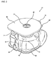
FIG. 2 is a front perspective view of a dust collecting unit of a cyclonic vacuum cleaner according to the present invention; -
FIG. 3 is a rear perspective view of the dust collecting unit of the cyclonic vacuum cleaner according to the present invention; -
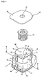
FIG. 4 is an exploded perspective view of the dust collecting unit of the cyclonic vacuum cleaner according to the present invention; -
FIG. 5 is a sectional view taken along line B-B' ofFIG. 4 ; -
FIG. 6 is a view illustrating an operating state of the cyclonic vacuum cleaner according to the present invention; -
FIG. 7 is a sectional view of a bottom cover fixing means, taken along line A-A' ofFIG. 4 ; and -
FIG. 8 is a view illustrating a state where a bottom surface of the dust collecting chamber is opened. - Hereinafter, a preferred embodiment of a dust collecting unit for a vacuum cleaner according to the present invention will be described in detail with reference to the accompanying drawings. Throughout the drawings, like reference numerals are used to designate like elements.
-
FIG. 2 is a front perspective view of a dust collecting unit for a cyclonic vacuum cleaner according to the present invention,FIG. 3 is a rear perspective view of the dust collecting unit for the cyclonic vacuum cleaner according to the present invention,FIG. 4 is an exploded perspective view of the dust collecting unit for the cyclonic vacuum cleaner according to the present invention, andFIG. 5 is a sectional view taken along line B-B' ofFIG. 4 . - Referring to these figures, the vacuum cleaner of the present invention comprises a
cover 30 for covering an upper end of thedust collecting unit 11 to protect inner parts and hermetically sealing the unit to prevent sucked air from leaking out, afilter 40 installed downward from the cover around anoutlet 31 formed near the center of the cover, and adust collecting casing 80 attached to a bottom side of thecover 30. - More specifically, near the center of the
cover 30 is formed theoutlet 31 through which clean air with dust and dirt filtered out from the air sucked in thedust collecting casing 80 is discharged. Thefilter 40 in which a fine filtering structure is implemented is positioned below theoutlet 31 to filter out fine particles. - The
filter 40 is cylindrical and is formed with the fine filtering structure on an outer periphery thereof. The air in thedust collecting casing 80 is filtrated by thefilter 40 and then discharged to the outside through theoutlet 31. - Further, the
dust collecting casing 80 comprises aninlet 71 through which air is introduced from the main body of the vacuum cleaner into thedust collecting unit 11, a cylindricaldust separation chamber 70 in which the air sucked through theinlet 71 swirls by a centrifugal force and the dust and dirt fallen by their own weight are separated from the air, and a maindust collecting chamber 50 which is formed below thedust separation chamber 70 so that the dust and dirt fallen by their own weight are accumulated. - Further, the
dust collecting casing 80 includes apartition plate 73 which is installed in thedust separating chamber 70 to horizontally partition the maindust collecting chamber 50. At an outer periphery of thepartition plate 73 is formed an opening through which the dirt and dust swirling in thedust separating chamber 70 are dropped into the maindust collecting chamber 50. - The main
dust collecting chamber 50 is divided by thepartition plate 73 into an upper part (an cyclonic part) where air flows cyclonically and a lower part (a collecting part) without cyclonic air flow. - The
partition plate 73 may be integrally formed in thedirt separating chamber 70. Alternatively, thepartition plate 73 may be installed in the dirt separating chamber using additional fixing means so that it can be opened and closed. - Due to their light weight, the dust and dirt may not be dropped into the
main chamber 50 through the opening 74. To separate such light dirt and dust, thedust collecting casing 80 further includes an upper communicatinghole 72 formed at an upper circumferential surface of thedust separating chamber 70 and an auxiliarydust collecting chamber 60 formed at one side of the maindust collecting chamber 50. - Further, in the dust collecting casing are formed a
boundary wall 75 which partitions the auxiliarydust collecting chamber 60 and the maindust collecting chamber 50 and a lower communicatinghole 52 which penetrates theboundary wall 75 and communicates the maindust collecting chamber 50 and the auxiliarydust collecting chamber 60 with each other to enhance dust collection efficiency. - A
bottom cover 53 for causing bottom faces of the main and auxiliarydust collecting chambers hinge portion 81 for pivoting the wholelower plate 53 thereon, and a lower plate fixing means 54 for maintaining thelower plate 53 into its fixed location are further formed. - A
grip 12 which extends vertically to allow a user to grip is also formed on an outer surface of thedust collecting casing 80. Astop plate 51 which protrudes inwardly from an inner surface and extends to a certain level in a vertical direction is formed to prevent the dust and dirt from swirling in the maindust collecting chamber 50, thereby increasing a suction force. - Further, the
inlet 71 is formed tangentially to thedust separating chamber 70 to allow the sucked air to swirl such that the dust and dirt can be separated from the air due to a centrifugal force of the air. - Furthermore, a
cover protrusion 32 for allowing the user to easily detach the cover from thedust collecting unit 11 is formed at an outer periphery of thecover 30. - More specifically, the auxiliary
dust collecting chamber 60 for collecting fine dust in the maindust collecting chamber 50 is formed at a front side of the maindust collecting chamber 50, i.e. at a side opposite to thegrip 12. The auxiliarydust collecting chamber 60 is formed as another space divided from the maindust collecting chamber 50 by theboundary wall 75 that is positioned between the two chambers and corresponds to a side wall of the maindust collecting chamber 50. The fine dust swirling continuously in an upper space of the maindust collecting chamber 50 is collected in the auxiliarydust collecting chamber 60 via the upper communicatinghole 72. A probable influence caused by different air flow, which can be exerted mutually on the maindust collecting chamber 50 and the auxiliarydust collecting chamber 60, can be reduced by theboundary wall 75. - Only the upper and lower communicating
holes boundary wall 75 of the maindust collecting chamber 50 to cause the main and auxiliarydust collecting chambers - The upper communicating
hole 72 allows the fine dust in the sucked air, which cannot be freely dropped into the main dust collecting chamber due to its light weight and continuously swirls in an upper space of thedust separating chamber 70, to move into the auxiliarydust collecting chamber 60. Since the upper communicatinghole 72 allows the fine dust drifting and swirling along an upper wall of thedust separating chamber 70 to be introduce into the auxiliarydust collecting chamber 60, it is preferred that the upper communicatinghole 72 be formed at an upper portion of theboundary wall 75. - In addition, the lower communicating
hole 52 is formed at a lower portion of theboundary wall 75 to allow a part of the dust and dirt accumulated in the maindust collecting chamber 50 to be accommodated in the auxiliarydust collecting chamber 60. - More specifically, large dust is primarily collected in the main
dust collecting chamber 50 of thedust collecting casing 80 whereas fine dust is collected in the auxiliarydust collecting chamber 60. Thus, even though the maindust collecting chamber 50 is fully filled with the dust, there may occur a case where the auxiliarydust collecting chamber 60 still has a space enough to accommodate the dust. The lower communicatinghole 52 is formed to move a part of the dust in the maindust collecting chamber 50 to the auxiliarydust collecting chamber 60 in such a case where the dust is overflowed from the maindust collecting chamber 50. - As described above, in a case where the main
dust collecting chamber 50 is fully filled with the dust, the dust in the maindust collecting chamber 50 can be moved naturally to the auxiliarydust collecting chamber 60 through the lower communicatinghole 52 so that the entire dust collecting space of thedust collecting casing 80 can be more efficiently used. - Further, since the lower communicating
hole 52 is formed, a part of the air introduced from theinlet 71 can flow through the upper and lower communicatingholes dust collecting chamber 50. Thus, a flow path from the inlet to the chamber is not interrupted but continued so that a loss of the suction force can be prevented. If the lower communicatinghole 52 is not formed, a vortex is formed in the auxiliarydust collecting chamber 60 due to the air passed through the upper communicatinghole 72. As a result, since the air corresponding to the formed vortex cannot flow, a loss of the suction force occurs. - The
cylindrical filter 40 is installed below theoutlet 31 and detachably mounted on a bottom surface thecover 30 such that the cylindrical interior thereof communicates with theoutlet 31. The air from which the dust and dirt are filtered out is further purified while passing through thefilter 40, and the purified air is then discharged to the outside of the main body. - Referring to
FIG. 5 , one ormore stop plates dust separating chamber 70 which constitutes the boundary wall of the maindust collecting chamber 50. It can also be seen from this figure that theboundary wall 75 for dividing the auxiliarydust collecting chamber 60 from the maindust collecting chamber 50 and the lower communicatinghole 52 penetrating theboundary wall 75 are further formed. - The
stop plates dust collecting chamber 50 from swirling to allow the dust and dirt to be accumulated near the plates. In other words, the dust and dirt do not continuously swirl but are accumulated in the maindust collecting chamber 50 so that the collected dust and dirt are not again discharged from the main dust collecting chamber. -
FIG. 5 illustrates an air flow direction designated by arrows. That is,FIG. 5 schematically shows that the dust and dirt are trapped and stopped by thestop plates -
FIG. 6 is a view illustrating an operating state of the cyclonic vacuum cleaner according to the present invention. - An operation for collecting the dust and dirt in the
dust collecting casing 80 will be described with reference toFIG. 6 . Once the vacuum cleaner is operated, the air containing the dust and dirt is sucked into thedust collecting casing 80 through the aforementioned suction nozzle, extension tube and suction tube and then through theinlet 71 of thedust collecting casing 80. Then, the sucked air swirls along the inner wall surface of the cylindricaldust separating chamber 70. At this time, the heavy dust and dirt are moved into the maindust collecting chamber 50 through theopening 74 formed on the outer periphery of thepartition plate 73. - The fine dust, which cannot be dropped due to its light weight while swirling along the inner surface of the
dust separating chamber 70, is collected into the auxiliarydust collecting chamber 60 through the upper communicatinghole 72 of theboundary wall 75. At this time, the air is again moved into the maindust collecting chamber 50 through the upper and lower communicatingholes filter 40. - In addition, a part of the dust and dirt accumulated in the main
dust collecting chamber 50 is moved to the auxiliarydust collecting chamber 60 via the lower communicatinghole 52. Thus, even though the dust and dirt are accumulated beyond a certain level in the maindust collecting chamber 50, the air suction efficiency of the vacuum cleaner is not influenced by the accumulated dust and dirt. - As described above, arrows shown in
FIG. 6 specifically indicate the circulation paths of the air sucked in the dust collecting unit. -
FIG. 7 is a sectional view taken along line A-A' ofFIG. 4 , and more specifically shows a sectional view of the bottom cover fixing means. - Referring to
FIG. 7 , the bottom cover fixing means 54 for locking thebottom cover 53 of the dust collecting chamber comprises aprotrusion 82 which protrudes outwardly from the outer surface of thedust collecting casing 80, an operatingmember 83 formed at a level corresponding to a protruding end of theprotrusion 82, ahinge shaft 84 for allowing the operating member to be pivotally hinged to theprotrusion 82 at the protruding end, anmovable latch 85 formed at a lowermost end of the operatingmember 83, astationary latch 86 integrally formed with thebottom cover 53 to protrude upwardly from a rear end of thebottom cover 53, and anelastic member 87 mounted between a back surface of an upper end of the operatingmember 83 and a front surface of thedust collecting casing 80. - The operation of the bottom cover fixing means so constructed will be now explained. The
bottom cover 53 of the dust collecting chamber is not opened when themovable latch 85 and thestationary latch 86 are engaged with each other. However, if the operatingmember 83 is pivoted on thehinge shaft 84 and themovable latch 85 is then disengaged from thestationary latch 86, thebottom cover 53 is pivoted on the hinge portion 81 (FIG. 4 ) by its weight so that the bottom faces of thedust collecting chambers - When the bottom faces, i.e. the
bottom cover 53, of thedust collecting chambers dust collecting chambers dust collecting chambers - To conduct the operation for discharging the duct and dirt, the user of the vacuum cleaner only pushes an upper portion of the operating
member 83 inwardly. Further, when an external force is not applied to the upper portion of the operating member, the operatingmember 83 is restored to its original position due to a restoring force of theelastic member 87. - To fix the
elastic member 87 at a predetermined position, first andsecond supports member 83 and the front surface of thedust collecting casing 80, respectively. Then, both ends of theelastic member 87 are fitted around the first andsecond supports elastic member 87 cannot be removed from the supports. - To this end, the
bottom cover 53 is designed to cover the whole bottom faces of the main and auxiliarydust collecting chambers bottom cover 53 is opened by the opening operation of the bottom cover fixing means 54, all the dust and dirt collected in thedust collecting chambers -
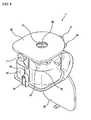
FIG. 8 is a view illustrating a state where the bottom cover fixing means 54 has been opened. In a case where the bottom faces of the dust collecting chambers are opened as shown inFIG. 8 , the dust and dirt accumulated in thedust collecting chambers grip 12 of the dust collecting unit. - According to the present invention so constructed, the following advantages can be expected.
- First, since an amount of the air to be sucked and the efficiency of collecting the dust and dirt can be increased, even a small capacity motor can be used. Therefore, there is an advantage in that the low-price vacuum cleaner can be implemented.
- Further, since the dust and dirt accumulated in the vacuum cleaner can be easily removed, there is another advantage in that the convenience of use of the vacuum cleaner is enhanced.
- Furthermore, since the auxiliary dust collecting chamber is formed together with the main dust collection chamber, there is still another advantage in that the amount of dust and dirt to be accumulated can be further increased and even the fine dust which cannot be collected in the main dust collecting chamber can be completely removed.
Claims (10)
- A dust collecting unit (11) for a vacuum cleaner, comprising:a dust separating chamber (70) with an air inlet (71) formed on an outer surface thereof and an air outlet formed on one side thereof;a main dust collecting chamber (50) formed in the dust separating chamber (70) for separating dust and dirt in a cyclonic fashion;an auxiliary dust collecting chamber (60) formed at one side of the main dust collecting chamber (50); anda partition plate (73) partitioning the main dust collecting chamber (50) into a cyclonic part where air flows cyclonically and a collecting part without cyclonic air flow,wherein the partition plate (73) includes at least one opening (74);
characterized in that
a first communicating hole (72) is formed at an upper side of the main dust collecting chamber (50); and
a second communicating hole (52) is formed at a lower side of the main dust collecting chamber (50);
wherein said first and second communicating holes (72;52) communicate the main dust collecting chamber (50) and the auxiliary dust collecting chamber (60) with each other. - The dust collecting unit as claimed in claim 1, wherein the inlet (71) is formed on the outer surface of the dust separating chamber (70) in a tangential direction.
- The dust collecting unit as claimed in claim 1 or 2, further comprising a cover (30) which is mounted to open and close a top face of the dust separating chamber (70) and is formed with an opening (31) at the center thereof through which air is to be discharged.
- The dust collecting unit as claimed in any one of claims 1 to 3, further comprising a filter (40) mounted to the dust separating chamber (70) for filtering out fine dust.
- The dust collecting unit as claimed in any one of claims 1 to 4, wherein the partition plate (73) is integrally formed with a dust collecting casing (80) at an inner surface thereof.
- The dust collecting unit as claimed in any one of claims 1 to 5, wherein at least one stop plate (511-514) is formed on an inner surface of the main dust collecting chamber (50).
- The dust collecting unit as claimed in any one of claims 1 to 6, further comprising a bottom cover (53) which is openably mounted to the bottom of the dust separating chamber (70).
- The dust collecting unit as claimed in any one of claims 1 to 7, wherein the one or more openings (74) are formed at an outer periphery of the partition plate (73).
- The dust collecting unit as claimed in any one of claims 1 to 8, wherein the main dust collecting chamber (50) is divided into an upper cyclonic part and a lower collecting part.
- The dust collecting unit as claimed in any one of claims 1 to 9, wherein said first communicating hole (72) is formed at an upper portion of a boundary wall (75) which partitions the main dust collecting chamber (50) and the auxiliary dust collecting chamber (60), and said second communicating hole (52) is formed at a lower portion of said boundary wall (75).
Applications Claiming Priority (2)
| Application Number | Priority Date | Filing Date | Title |
|---|---|---|---|
| KR1020030029630A KR100587099B1 (en) | 2003-05-10 | 2003-05-10 | Dust removing unit of cyclone cleaner |
| KR2003029630 | 2003-05-10 |
Publications (3)
| Publication Number | Publication Date |
|---|---|
| EP1477099A2 EP1477099A2 (en) | 2004-11-17 |
| EP1477099A3 EP1477099A3 (en) | 2007-06-20 |
| EP1477099B1 true EP1477099B1 (en) | 2009-08-12 |
Family
ID=36969232
Family Applications (1)
| Application Number | Title | Priority Date | Filing Date |
|---|---|---|---|
| EP04007221A Expired - Fee Related EP1477099B1 (en) | 2003-05-10 | 2004-03-25 | Dust collecting unit of vacuum cleaner |
Country Status (6)
| Country | Link |
|---|---|
| US (2) | US7086119B2 (en) |
| EP (1) | EP1477099B1 (en) |
| JP (1) | JP4084323B2 (en) |
| KR (1) | KR100587099B1 (en) |
| DE (1) | DE602004022481D1 (en) |
| RU (1) | RU2260367C1 (en) |
Families Citing this family (47)
| Publication number | Priority date | Publication date | Assignee | Title |
|---|---|---|---|---|
| US7343643B2 (en) * | 2003-03-17 | 2008-03-18 | Panasonic Corporation Of North America | Selective bag or bagless cleaning system |
| US7235121B2 (en) * | 2003-12-26 | 2007-06-26 | West Timothy J | Externally removable vacuum cleaner filter apparatus |
| GB0402847D0 (en) * | 2004-02-10 | 2004-03-17 | Black & Decker Inc | Filter assembly for vacuum cleaner and vacuum cleaner incorporating such assembly |
| US7640623B2 (en) * | 2004-03-11 | 2010-01-05 | Lg Electronics Inc. | Vacuum cleaner |
| US20050198771A1 (en) * | 2004-03-11 | 2005-09-15 | Lg Electronics Inc. | Vacuum cleaner |
| US20050198769A1 (en) * | 2004-03-11 | 2005-09-15 | Lg Electronics Inc. | Vacuum cleaner |
| US7779507B2 (en) * | 2004-03-11 | 2010-08-24 | Lg Electronics Inc. | Vacuum cleaner |
| US7779506B2 (en) * | 2004-03-11 | 2010-08-24 | Lg Electronics Inc. | Vacuum cleaner |
| US7669282B2 (en) * | 2004-03-11 | 2010-03-02 | Lg Electronics Inc. | Vacuum cleaner |
| KR100554238B1 (en) * | 2004-11-15 | 2006-02-22 | 삼성광주전자 주식회사 | A cyclone dust-separating apparatus |
| KR101143807B1 (en) * | 2005-04-11 | 2012-05-11 | 엘지전자 주식회사 | Dust and dirt collecting unit for vacuum cleaner |
| US20070144116A1 (en) * | 2005-12-23 | 2007-06-28 | Samsung Electronics Co., Ltd. | Cyclonic cleaner |
| KR100838885B1 (en) * | 2007-01-24 | 2008-06-16 | 엘지전자 주식회사 | Vacuum cleaner |
| EP1949967B1 (en) * | 2007-01-24 | 2015-03-25 | LG Electronics Inc. | Dust collector of a vacuum cleaner |
| US9119511B2 (en) | 2007-03-02 | 2015-09-01 | Carl L. C. Kah, Jr. | Centrifugal dirt separation configurations for household-type and shop-type vacuum cleaners |
| WO2008109081A1 (en) | 2007-03-02 | 2008-09-12 | Kah Carl L C Jr | Centrifugal dirt separation configurations for household-type and shop-type vacuum cleaners |
| MX2010000383A (en) * | 2007-07-09 | 2010-04-22 | Johnson & Son Inc S C | Handheld portable devices for touchless particulate matter removal. |
| KR100842966B1 (en) * | 2007-07-19 | 2008-07-01 | 엘지전자 주식회사 | Dust collecting apparatus of vaccum cleaner |
| US20090205161A1 (en) * | 2007-12-19 | 2009-08-20 | Wayne Ernest Conrad | Configuration of a cyclone assembly and surface cleaning apparatus having same |
| EP2237892A1 (en) * | 2007-12-19 | 2010-10-13 | G.B.D. Corp. | Cyclone separator assembly and surface cleaning apparatus having same |
| US8191203B2 (en) * | 2008-01-16 | 2012-06-05 | Samsung Electronics Co., Ltd. | Dust receptacle and vacuum cleaner having the same |
| KR20090099850A (en) * | 2008-03-18 | 2009-09-23 | 삼성광주전자 주식회사 | Dust case and cyclone dust collecting device having the same |
| KR101524791B1 (en) * | 2008-11-07 | 2015-06-03 | 삼성전자주식회사 | Cyclone dust collecting appapatus and cleaner having the same |
| WO2010065115A2 (en) | 2008-12-03 | 2010-06-10 | S. C. Johnson & Son, Inc. | Portable devices for touchless particulate matter removal |
| US9211044B2 (en) | 2011-03-04 | 2015-12-15 | Omachron Intellectual Property Inc. | Compact surface cleaning apparatus |
| DE102009035619A1 (en) * | 2009-07-31 | 2011-04-21 | BSH Bosch und Siemens Hausgeräte GmbH | Vacuum cleaner with Staubabscheideeinheit |
| US20110056045A1 (en) * | 2009-09-10 | 2011-03-10 | Electrolux Home Care Products, Inc. | Dirt Cup Latch Mechanism |
| US8875340B2 (en) | 2010-03-12 | 2014-11-04 | G.B.D. Corp. | Surface cleaning apparatus with enhanced operability |
| US8997309B2 (en) | 2012-03-02 | 2015-04-07 | G.B.D. Corp. | Surface cleaning apparatus |
| EP2959817A1 (en) * | 2011-06-02 | 2015-12-30 | Mitsubishi Electric Corporation | Electric vacuum cleaner |
| TWI581747B (en) * | 2013-01-30 | 2017-05-11 | 三菱電機股份有限公司 | Electric vacuum cleaner |
| JP5935708B2 (en) * | 2013-01-30 | 2016-06-15 | 三菱電機株式会社 | Electric vacuum cleaner |
| US20140237764A1 (en) | 2013-02-28 | 2014-08-28 | G.B.D. Corp. | Cyclone such as for use in a surface cleaning apparatus |
| US9295995B2 (en) | 2013-02-28 | 2016-03-29 | Omachron Intellectual Property Inc. | Cyclone such as for use in a surface cleaning apparatus |
| US9326652B2 (en) | 2013-02-28 | 2016-05-03 | Omachron Intellectual Property Inc. | Surface cleaning apparatus |
| US9227201B2 (en) | 2013-02-28 | 2016-01-05 | Omachron Intellectual Property Inc. | Cyclone such as for use in a surface cleaning apparatus |
| US9820621B2 (en) | 2013-02-28 | 2017-11-21 | Omachron Intellectual Property Inc. | Surface cleaning apparatus |
| US9238235B2 (en) | 2013-02-28 | 2016-01-19 | Omachron Intellectual Property Inc. | Cyclone such as for use in a surface cleaning apparatus |
| US9227151B2 (en) | 2013-02-28 | 2016-01-05 | Omachron Intellectual Property Inc. | Cyclone such as for use in a surface cleaning apparatus |
| US9451855B2 (en) | 2013-02-28 | 2016-09-27 | Omachron Intellectual Property Inc. | Surface cleaning apparatus |
| FR3007269B1 (en) * | 2013-06-21 | 2015-07-03 | Seb Sa | DEVICE FOR RECOVERING DUST FROM A VACUUM CLEANER |
| US10631697B2 (en) | 2014-02-14 | 2020-04-28 | Techtronic Industries Co. Ltd. | Separator configuration |
| WO2016065151A1 (en) | 2014-10-22 | 2016-04-28 | Techtronic Industries Co. Ltd. | Handheld vacuum cleaner |
| WO2016065146A1 (en) | 2014-10-22 | 2016-04-28 | Techtronic Industries Co. Ltd. | Vacuum cleaner having cyclonic separator |
| CN110123203A (en) | 2014-10-22 | 2019-08-16 | 创科实业有限公司 | Vacuum cleaner with cyclone separator |
| JP5933099B2 (en) * | 2015-11-20 | 2016-06-08 | シャープ株式会社 | Dust collector and self-propelled vacuum cleaner provided with the same |
| US11246462B2 (en) * | 2019-11-18 | 2022-02-15 | Omachron Intellectual Property Inc. | Multi-inlet cyclone |
Family Cites Families (37)
| Publication number | Priority date | Publication date | Assignee | Title |
|---|---|---|---|---|
| US2432757A (en) * | 1945-06-13 | 1947-12-16 | Beaumont Birch Company | Ash and dust separator |
| US3856488A (en) | 1972-09-05 | 1974-12-24 | Mitsubishi Electric Corp | Electric vacuum cleaner |
| NL7613475A (en) * | 1976-12-03 | 1978-06-06 | Philips Nv | VACUUM CLEANER. |
| JPS56114755A (en) | 1980-02-15 | 1981-09-09 | Yokogawa Hokushin Electric Corp | Detecting apparatus of ignition and flame extinction of gas analyzer |
| CA1236922A (en) | 1983-11-30 | 1988-05-17 | Paul Mermelstein | Method and apparatus for coding digital signals |
| JPH074654B2 (en) | 1986-12-08 | 1995-01-25 | 扶桑軽合金株式会社 | Product removal method in die casting |
| CA2034694C (en) | 1990-02-01 | 2003-04-08 | Antonio Gutierrez | Ethylene alpha-olefin polymer substituted mannich base useful as multifunctional viscosity index improver for oleaginous composition |
| RU2050825C1 (en) | 1993-04-20 | 1995-12-27 | Акционерное общество "Уралэлектротяжмаш" | Dust collector for the vacuum cleaner |
| US6003196A (en) * | 1998-01-09 | 1999-12-21 | Royal Appliance Mfg. Co. | Upright vacuum cleaner with cyclonic airflow |
| US6168641B1 (en) | 1998-06-26 | 2001-01-02 | Akteibolaget Electrolux | Cyclone separator device for a vacuum cleaner |
| US7096531B2 (en) | 1998-12-01 | 2006-08-29 | The Procter & Gamble Company | Cleaning implement for cleaning a surface |
| GB2344745B (en) | 1998-12-18 | 2002-06-05 | Notetry Ltd | Vacuum cleaner |
| US6334234B1 (en) * | 1999-01-08 | 2002-01-01 | Fantom Technologies Inc. | Cleaner head for a vacuum cleaner |
| US6228260B1 (en) * | 1999-07-27 | 2001-05-08 | G. B. D. Corp. | Apparatus for separating particles from a cyclonic fluid flow |
| US6440197B1 (en) * | 1999-07-27 | 2002-08-27 | G.B.D. Corp. | Apparatus and method separating particles from a cyclonic fluid flow including an apertured particle separation member within a cyclonic flow region |
| GB9930332D0 (en) | 1999-12-22 | 2000-02-09 | Notetry Ltd | Cyclonic separating apparatus |
| US6341404B1 (en) | 2000-01-13 | 2002-01-29 | Royal Appliance Mfg. Co. | Upright vacuum cleaner with cyclonic airflow pathway |
| US6910245B2 (en) * | 2000-01-14 | 2005-06-28 | White Consolidated Industries, Inc. | Upright vacuum cleaner with cyclonic air path |
| KR100406638B1 (en) | 2000-01-22 | 2003-11-22 | 삼성광주전자 주식회사 | Vacuum cleaner |
| KR100510644B1 (en) * | 2000-02-17 | 2005-08-31 | 엘지전자 주식회사 | cyclone dust collector |
| US6596044B1 (en) | 2000-03-06 | 2003-07-22 | The Hoover Company | Dirt collecting system for a vacuum cleaner |
| GB2363744B (en) * | 2000-06-24 | 2002-11-13 | Samsung Kwangju Electronics Co | Upright type vacuum cleaner having a cyclone-type dust collector |
| WO2002003844A1 (en) | 2000-07-06 | 2002-01-17 | John Herbert North | Improved dust/particle collecting arrangement for cyclone separators |
| KR100437364B1 (en) * | 2000-07-26 | 2004-06-25 | 삼성광주전자 주식회사 | Cyclone dust-collecting apparatus for Vaccum Cleaner |
| KR100437371B1 (en) | 2000-07-26 | 2004-06-25 | 삼성광주전자 주식회사 | Cyclone dust-collecting apparatus for Vaccum Cleaner |
| KR100377015B1 (en) * | 2000-08-07 | 2003-03-26 | 삼성광주전자 주식회사 | Cyclone dust-collecting apparatus for Vacuum Cleaner |
| JP3626413B2 (en) | 2000-08-19 | 2005-03-09 | エルジー電子株式会社 | Dust collector and vacuum cleaner using the same |
| KR100377016B1 (en) * | 2000-10-19 | 2003-03-26 | 삼성광주전자 주식회사 | Upright type Vacuum Cleaner |
| KR100437369B1 (en) * | 2001-01-10 | 2004-06-25 | 삼성광주전자 주식회사 | Cyclone dust-collecting apparatus for Vacuum Cleaner |
| US6436160B1 (en) * | 2001-01-11 | 2002-08-20 | Royal Appliance Mfg. Co. | Dirt cup assembly for vacuum cleaner |
| ES2265492T3 (en) | 2001-02-24 | 2007-02-16 | Dyson Technology Limited | A VACUUM CLEANER. |
| US6598263B2 (en) * | 2001-05-09 | 2003-07-29 | The Hoover Company | Vacuum cleaner dirt collecting system with filter cleaning devices |
| US6613129B2 (en) | 2001-06-22 | 2003-09-02 | Euro-Pro Corporation | Cyclone and dust filter vacuum cleaner |
| KR100445470B1 (en) * | 2001-10-09 | 2004-08-21 | 엘지전자 주식회사 | Dirt and dust collecting casing and vacuum cleaner body having the same |
| KR100476423B1 (en) * | 2002-11-15 | 2005-03-17 | 엘지전자 주식회사 | Dust and dirt collecting unit for vacuum cleaner |
| KR100483545B1 (en) * | 2002-11-29 | 2005-04-18 | 삼성광주전자 주식회사 | Cyclone-type dust collecting apparatus for vacuum cleaner |
| US7544224B2 (en) * | 2003-08-05 | 2009-06-09 | Electrolux Home Care Products, Inc. | Cyclonic vacuum cleaner |
-
2003
- 2003-05-10 KR KR1020030029630A patent/KR100587099B1/en active IP Right Grant
-
2004
- 2004-03-01 US US10/788,396 patent/US7086119B2/en not_active Expired - Fee Related
- 2004-03-09 JP JP2004065932A patent/JP4084323B2/en not_active Expired - Fee Related
- 2004-03-23 RU RU2004108669/12A patent/RU2260367C1/en not_active IP Right Cessation
- 2004-03-25 EP EP04007221A patent/EP1477099B1/en not_active Expired - Fee Related
- 2004-03-25 DE DE602004022481T patent/DE602004022481D1/en not_active Expired - Fee Related
-
2006
- 2006-04-25 US US11/410,092 patent/US7409744B2/en not_active Expired - Lifetime
Also Published As
| Publication number | Publication date |
|---|---|
| US7409744B2 (en) | 2008-08-12 |
| KR20040096725A (en) | 2004-11-17 |
| JP4084323B2 (en) | 2008-04-30 |
| EP1477099A3 (en) | 2007-06-20 |
| JP2004329880A (en) | 2004-11-25 |
| US20060200934A1 (en) | 2006-09-14 |
| EP1477099A2 (en) | 2004-11-17 |
| KR100587099B1 (en) | 2006-06-07 |
| RU2260367C1 (en) | 2005-09-20 |
| US7086119B2 (en) | 2006-08-08 |
| DE602004022481D1 (en) | 2009-09-24 |
| US20040177472A1 (en) | 2004-09-16 |
Similar Documents
| Publication | Publication Date | Title |
|---|---|---|
| EP1477099B1 (en) | Dust collecting unit of vacuum cleaner | |
| US6977003B2 (en) | Cyclone dust-collecting apparatus of vacuum cleaner | |
| US7398578B2 (en) | Cyclone dust collecting device for use in a vacuum cleaner | |
| KR100549990B1 (en) | Dust collecting apparatus for vacuum cleaner | |
| US6810558B2 (en) | Cyclone dust collecting apparatus for use in vacuum cleaner | |
| KR101248722B1 (en) | Dust Collector and Vacuum Cleaner Having the Same | |
| KR100536506B1 (en) | A cyclone separating apparatus and vacumm cleaner equipped whth such a device | |
| JP2002051952A (en) | Vacuum cleaner | |
| KR20060037989A (en) | Collecting chamber for a vacuum cleaner | |
| KR20070111239A (en) | Vaccum cleaner | |
| EP1676514B1 (en) | Vacuum cleaner | |
| US20050005390A1 (en) | Filter assembly for vacuum cleaner | |
| KR20050013696A (en) | Dust removing unit in vacuum cleaner | |
| JP2010063661A (en) | Vacuum cleaner | |
| KR101741393B1 (en) | A vacuum cleaner | |
| GB2406066A (en) | Cyclonic dust-separating apparatus | |
| EP2277426B1 (en) | Vacuum cleaner | |
| JP7153708B2 (en) | Vacuum cleaner and its dust collector | |
| KR20120054225A (en) | A vacuum cleaner | |
| KR100593093B1 (en) | Dust removing unit in vacuum cleaner | |
| KR100833360B1 (en) | Dust and dirt collecting unit for vacuum cleaner | |
| KR20050066916A (en) | Up right type vacuum cleaner having dirt and dust casing | |
| KR20080076192A (en) | Vacuum cleaner and filter unit thereof |
Legal Events
| Date | Code | Title | Description |
|---|---|---|---|
| PUAI | Public reference made under article 153(3) epc to a published international application that has entered the european phase |
Free format text: ORIGINAL CODE: 0009012 |
|
| 17P | Request for examination filed |
Effective date: 20040325 |
|
| AK | Designated contracting states |
Kind code of ref document: A2 Designated state(s): AT BE BG CH CY CZ DE DK EE ES FI FR GB GR HU IE IT LI LU MC NL PL PT RO SE SI SK TR |
|
| AX | Request for extension of the european patent |
Extension state: AL LT LV MK |
|
| PUAL | Search report despatched |
Free format text: ORIGINAL CODE: 0009013 |
|
| AK | Designated contracting states |
Kind code of ref document: A3 Designated state(s): AT BE BG CH CY CZ DE DK EE ES FI FR GB GR HU IE IT LI LU MC NL PL PT RO SE SI SK TR |
|
| AX | Request for extension of the european patent |
Extension state: AL LT LV MK |
|
| AKX | Designation fees paid |
Designated state(s): DE ES FR GB IT |
|
| 17Q | First examination report despatched |
Effective date: 20080228 |
|
| GRAP | Despatch of communication of intention to grant a patent |
Free format text: ORIGINAL CODE: EPIDOSNIGR1 |
|
| GRAS | Grant fee paid |
Free format text: ORIGINAL CODE: EPIDOSNIGR3 |
|
| GRAA | (expected) grant |
Free format text: ORIGINAL CODE: 0009210 |
|
| AK | Designated contracting states |
Kind code of ref document: B1 Designated state(s): DE ES FR GB IT |
|
| REG | Reference to a national code |
Ref country code: GB Ref legal event code: FG4D |
|
| REF | Corresponds to: |
Ref document number: 602004022481 Country of ref document: DE Date of ref document: 20090924 Kind code of ref document: P |
|
| PG25 | Lapsed in a contracting state [announced via postgrant information from national office to epo] |
Ref country code: ES Free format text: LAPSE BECAUSE OF FAILURE TO SUBMIT A TRANSLATION OF THE DESCRIPTION OR TO PAY THE FEE WITHIN THE PRESCRIBED TIME-LIMIT Effective date: 20091123 |
|
| PLBE | No opposition filed within time limit |
Free format text: ORIGINAL CODE: 0009261 |
|
| STAA | Information on the status of an ep patent application or granted ep patent |
Free format text: STATUS: NO OPPOSITION FILED WITHIN TIME LIMIT |
|
| PGFP | Annual fee paid to national office [announced via postgrant information from national office to epo] |
Ref country code: GB Payment date: 20100322 Year of fee payment: 7 |
|
| 26N | No opposition filed |
Effective date: 20100517 |
|
| REG | Reference to a national code |
Ref country code: FR Ref legal event code: ST Effective date: 20101130 |
|
| PG25 | Lapsed in a contracting state [announced via postgrant information from national office to epo] |
Ref country code: FR Free format text: LAPSE BECAUSE OF NON-PAYMENT OF DUE FEES Effective date: 20100331 |
|
| PG25 | Lapsed in a contracting state [announced via postgrant information from national office to epo] |
Ref country code: DE Free format text: LAPSE BECAUSE OF NON-PAYMENT OF DUE FEES Effective date: 20101001 |
|
| PG25 | Lapsed in a contracting state [announced via postgrant information from national office to epo] |
Ref country code: IT Free format text: LAPSE BECAUSE OF FAILURE TO SUBMIT A TRANSLATION OF THE DESCRIPTION OR TO PAY THE FEE WITHIN THE PRESCRIBED TIME-LIMIT Effective date: 20090812 |
|
| GBPC | Gb: european patent ceased through non-payment of renewal fee |
Effective date: 20110325 |
|
| PG25 | Lapsed in a contracting state [announced via postgrant information from national office to epo] |
Ref country code: GB Free format text: LAPSE BECAUSE OF NON-PAYMENT OF DUE FEES Effective date: 20110325 |