EP1478313B1 - Vented vacuum bandage - Google Patents
Vented vacuum bandage Download PDFInfo
- Publication number
- EP1478313B1 EP1478313B1 EP02794392.7A EP02794392A EP1478313B1 EP 1478313 B1 EP1478313 B1 EP 1478313B1 EP 02794392 A EP02794392 A EP 02794392A EP 1478313 B1 EP1478313 B1 EP 1478313B1
- Authority
- EP
- European Patent Office
- Prior art keywords
- vacuum
- vent
- wound
- irrigation
- communication
- Prior art date
- Legal status (The legal status is an assumption and is not a legal conclusion. Google has not performed a legal analysis and makes no representation as to the accuracy of the status listed.)
- Expired - Lifetime
Links
Images


Classifications
-
- A—HUMAN NECESSITIES
- A61—MEDICAL OR VETERINARY SCIENCE; HYGIENE
- A61M—DEVICES FOR INTRODUCING MEDIA INTO, OR ONTO, THE BODY; DEVICES FOR TRANSDUCING BODY MEDIA OR FOR TAKING MEDIA FROM THE BODY; DEVICES FOR PRODUCING OR ENDING SLEEP OR STUPOR
- A61M39/00—Tubes, tube connectors, tube couplings, valves, access sites or the like, specially adapted for medical use
- A61M39/22—Valves or arrangement of valves
- A61M39/223—Multiway valves
-
- A—HUMAN NECESSITIES
- A61—MEDICAL OR VETERINARY SCIENCE; HYGIENE
- A61M—DEVICES FOR INTRODUCING MEDIA INTO, OR ONTO, THE BODY; DEVICES FOR TRANSDUCING BODY MEDIA OR FOR TAKING MEDIA FROM THE BODY; DEVICES FOR PRODUCING OR ENDING SLEEP OR STUPOR
- A61M1/00—Suction or pumping devices for medical purposes; Devices for carrying-off, for treatment of, or for carrying-over, body-liquids; Drainage systems
- A61M1/71—Suction drainage systems
- A61M1/74—Suction control
-
- A—HUMAN NECESSITIES
- A61—MEDICAL OR VETERINARY SCIENCE; HYGIENE
- A61M—DEVICES FOR INTRODUCING MEDIA INTO, OR ONTO, THE BODY; DEVICES FOR TRANSDUCING BODY MEDIA OR FOR TAKING MEDIA FROM THE BODY; DEVICES FOR PRODUCING OR ENDING SLEEP OR STUPOR
- A61M1/00—Suction or pumping devices for medical purposes; Devices for carrying-off, for treatment of, or for carrying-over, body-liquids; Drainage systems
- A61M1/90—Negative pressure wound therapy devices, i.e. devices for applying suction to a wound to promote healing, e.g. including a vacuum dressing
- A61M1/92—Negative pressure wound therapy devices, i.e. devices for applying suction to a wound to promote healing, e.g. including a vacuum dressing with liquid supply means
-
- A—HUMAN NECESSITIES
- A61—MEDICAL OR VETERINARY SCIENCE; HYGIENE
- A61M—DEVICES FOR INTRODUCING MEDIA INTO, OR ONTO, THE BODY; DEVICES FOR TRANSDUCING BODY MEDIA OR FOR TAKING MEDIA FROM THE BODY; DEVICES FOR PRODUCING OR ENDING SLEEP OR STUPOR
- A61M1/00—Suction or pumping devices for medical purposes; Devices for carrying-off, for treatment of, or for carrying-over, body-liquids; Drainage systems
- A61M1/90—Negative pressure wound therapy devices, i.e. devices for applying suction to a wound to promote healing, e.g. including a vacuum dressing
- A61M1/96—Suction control thereof
- A61M1/964—Suction control thereof having venting means on or near the dressing
-
- A—HUMAN NECESSITIES
- A61—MEDICAL OR VETERINARY SCIENCE; HYGIENE
- A61M—DEVICES FOR INTRODUCING MEDIA INTO, OR ONTO, THE BODY; DEVICES FOR TRANSDUCING BODY MEDIA OR FOR TAKING MEDIA FROM THE BODY; DEVICES FOR PRODUCING OR ENDING SLEEP OR STUPOR
- A61M39/00—Tubes, tube connectors, tube couplings, valves, access sites or the like, specially adapted for medical use
- A61M39/10—Tube connectors; Tube couplings
- A61M2039/1077—Adapters, e.g. couplings adapting a connector to one or several other connectors
-
- A—HUMAN NECESSITIES
- A61—MEDICAL OR VETERINARY SCIENCE; HYGIENE
- A61M—DEVICES FOR INTRODUCING MEDIA INTO, OR ONTO, THE BODY; DEVICES FOR TRANSDUCING BODY MEDIA OR FOR TAKING MEDIA FROM THE BODY; DEVICES FOR PRODUCING OR ENDING SLEEP OR STUPOR
- A61M39/00—Tubes, tube connectors, tube couplings, valves, access sites or the like, specially adapted for medical use
- A61M39/10—Tube connectors; Tube couplings
- A61M2039/1083—Tube connectors; Tube couplings having a plurality of female connectors, e.g. Luer connectors
-
- A—HUMAN NECESSITIES
- A61—MEDICAL OR VETERINARY SCIENCE; HYGIENE
- A61M—DEVICES FOR INTRODUCING MEDIA INTO, OR ONTO, THE BODY; DEVICES FOR TRANSDUCING BODY MEDIA OR FOR TAKING MEDIA FROM THE BODY; DEVICES FOR PRODUCING OR ENDING SLEEP OR STUPOR
- A61M39/00—Tubes, tube connectors, tube couplings, valves, access sites or the like, specially adapted for medical use
- A61M39/10—Tube connectors; Tube couplings
- A61M2039/1088—Tube connectors; Tube couplings having a plurality of male connectors, e.g. Luer connectors
-
- A—HUMAN NECESSITIES
- A61—MEDICAL OR VETERINARY SCIENCE; HYGIENE
- A61M—DEVICES FOR INTRODUCING MEDIA INTO, OR ONTO, THE BODY; DEVICES FOR TRANSDUCING BODY MEDIA OR FOR TAKING MEDIA FROM THE BODY; DEVICES FOR PRODUCING OR ENDING SLEEP OR STUPOR
- A61M2205/00—General characteristics of the apparatus
- A61M2205/58—Means for facilitating use, e.g. by people with impaired vision
- A61M2205/583—Means for facilitating use, e.g. by people with impaired vision by visual feedback
-
- A—HUMAN NECESSITIES
- A61—MEDICAL OR VETERINARY SCIENCE; HYGIENE
- A61M—DEVICES FOR INTRODUCING MEDIA INTO, OR ONTO, THE BODY; DEVICES FOR TRANSDUCING BODY MEDIA OR FOR TAKING MEDIA FROM THE BODY; DEVICES FOR PRODUCING OR ENDING SLEEP OR STUPOR
- A61M39/00—Tubes, tube connectors, tube couplings, valves, access sites or the like, specially adapted for medical use
- A61M39/10—Tube connectors; Tube couplings
- A61M39/105—Multi-channel connectors or couplings, e.g. for connecting multi-lumen tubes
Definitions
- a wound bandage system for use with a wound, a negative pressure source, and an irrigation source, comprising a wound bandage, and a vent apparatus through which: (i) ambient atmosphere vents to the wound bandage, (ii) irrigation fluid flows from the irrigation source to the wound bandage, and (iii) negative pressure is communicated to the wound bandage.
- the bandage is configured to lie adjacent the wound to create a sealed environment about the wound.
- the vent is positioned between the bandage and the vacuum source.
- a vacuum passageway of the system extends between the bandage and the vacuum source, and a vent passageway of the system extends from the bandage to the vent in communication with the surrounding atmosphere.
- the vacuum passageway extends through the vent to the vacuum source.
- a vacuum bandage system including a controller of the system is disclosed in U.S. Patent Application No. 10/159,583 filed on May 31, 2002 , titled WOUND TREATMENT APPARATUS and in US Patent Application No. 10/159,720 filed on May 31, 2002 , titled WOUND TREATMENT APPARATUS.
- inner conduit 36 and outer conduit 38 form separate passageways through vent 19.
- Inner conduit 36 is in communication with and forms a portion of vacuum/irrigation passageway 42 which extends through inner lumen 22, a portion of vent 19 and on to switch valve 50.
- Outer conduit 38 is in communication with and forms a portion of vent passageway 44, which extends through outer lumens 24 and a portion of vent 19. Vent passageway 44 is in communication with the atmosphere through filter 34.
- system 10 allows a caregiver to treat the wound using vented vacuum therapy through the use of vent 19 with vacuum source 16 and using vented irrigation therapy through the use of irrigation source 18 and vent 19.
- the caregiver moves diverter 51 to the vacuum position, shown in Fig. 8 , so that cut-out portion 63 of stem 64 connects opening 82 of vent connector 54 with opening 84 of vacuum connector 56. Therefore, irrigation connector 58 and irrigation passageway 72 are closed off and vacuum/irrigation passageway 42 is connected with vacuum connector 56 and vacuum passageway 70. Vent passageway 44 is kept open to the surrounding atmosphere.
- the negative pressure provided by vacuum source 16 above wound 12 acts to draw air in from the atmosphere through filter 34 of vent 19 and outer lumens 24.
- vent 19 is provided to aspirate the system 10 by creating an air flow path from the atmosphere to the bandage 14, over the wound, and out through inner lumen 22 in communication with vacuum source 16.
- irrigation passageway 72 of the irrigation connector 58 is in communication with the vacuum/irrigation passageway 42 of the vent connector 54.
- the vacuum passageway 70 is thus cut off from communication with the vacuum/irrigation passageway 42.
- Irrigation fluid is then dispensed from irrigation source 18 through irrigation passageway 72 of tube 76 and switch valve 50 to the vacuum/irrigation passageway 42 through vent connector 54, tube 52, vent 19, and inner lumen 22 of multi-lumen tube 20 to wound 12.
- Vent 19 is left in an open position to allow air to flow out of bandage 14 while fluid from irrigation source 18 is channeled to the wound. As mentioned above, it is also within the scope of this disclosure to provide non-vented irrigation of the wound by closing off vent 19 from the surrounding atmosphere while providing fluid to the wound through irrigation source 18.
- the lower level of holes communicate with outer conduit 38 and aperture 120 of vent 119.
- the upper holes of cylinder 164 form interconnecting passageways through cylinder 164 to selectively connect inner conduit 36 with vacuum conduit 156 and irrigation conduit 158 and the lower holes form passageways through cylinder 164 to selectively connect outer conduit 38 with vent 119, as is described in more detail below.
- a tube coupler 140 is provided for use with system 10. As shown in Fig. 17 , coupler 140 is positioned between bandage 14 and assembly 180. It is within the scope of this disclosure, however, to position a tube coupler between bandage 14 and assembly 80 shown in Fig. 1 . Coupler 140 connects or couples two multi-lumen tubes together. Coupler 140 allows a caregiver to disconnect a portion of system 10 between bandage 14 and assemblies 80 or 180. As shown in Figs. 17-19 , coupler 140 couples multi-lumen tube 20 to another multi-lumen tube 17.
- tube 200 is shown to include four venting lumens 214, it is within the scope of this disclosure to include a multi-lumen tube having one or more venting lumens in communication with the surrounding atmosphere, one or more vacuum lumens in communication with the vacuum source 16, and one or more irrigation lumens in communication with the irrigation source 18.
- an outer diameter 234 of tube 220 is 0.375 inch (9.53 mm)
- a diameter 236 of vacuum lumen 222 is 0.125 inch (3.175 mm)
- a diameter 238 of irrigation lumen 224 is 0.125 inch (3.175 mm)
- a diameter 240 of each outer venting lumen 226 is 0.020 inch (0.508 mm).
- tube 220 includes the above dimensions, it is within the scope of this disclosure to provide any suitable multi-lumen tube having lumens of any suitable size.
- vent 219 is used during both vacuum and irrigation modes of the system. As mentioned before with respect to vents 19 and 119, vent 219 provides increased air flow through bandage 14 and above wound 200. Vent 219 also creates an open system and prevents the system from becoming static. Vent 219 further maintains separate vacuum and irrigation passageways. As mentioned before with respect to vents 19, 119, it is within the scope of the disclosure for the caregiver to close off vent 160 while vacuuming or irrigating wound 200. Vent 219 may also be closed in a number of ways. For example, a cap or a valve (not shown) may be coupled to filter 34 or filter housing 40 to prevent air flow through filter 34. It is within the scope of this disclosure to include a vent having other suitable means of preventing air flow therethrough.
- Connecter 423 is a tubal port coupled to a top surface 436 of cover 422 and in communication with port 440 of cover 422.
- connector 423 it is within the scope of this disclosure for connector 423 to be a separate component of member 419 which is coupled to cover 422 or for connecter 423 to be coupled to cover 422 by being molded integrally with cover 422.
- Connector 423 includes a passageway formed at a right-angle.
- the passageway in connecter 423 has a vertical portion 425 that communicates with port 440 and a horizontal portion 427 that communicates with vertical portion 425.
- Connector 423 connects with tube 441 through the coupler 498 to provide a horizontal tube attachment for tube 441.
- Cover 422 includes a bottom surface 434 and top surface 436, as shown in Fig. 29 . Bottom surface 434 engages opposite surface 426 of layer 420, as shown in Fig. 30 .
- vent line 462 and tube 441 are integrally coupled to each other.
- vent line 462 includes an outer wall 492 and tube 441 includes an outer wall 494.
- a portion of outer wall 492 is integrally coupled to a portion of outer wall 494.
- An external coupler 468 for example, is not required to maintain the parallel relationship of vent line 462 and tube 441 of combination 490.
- combination 490 is extruded or manufactured as a single tube having two passages or lumens.
Description
- The present disclosure relates to vacuum therapy wound treatment systems including a vacuum bandage coupled to a vacuum source and an irrigation source.
- The prior art contemplates that chronic wounds may be treated by providing a vacuum in the space above the wound to promote healing. A number of prior art references teach the value of the vacuum bandage or the provision of vacuum in the space above the surface of a chronic wound.
- A vacuum bandage is a bandage having a cover for sealing about the outer perimeter of the wound and under which a vacuum is established to act on the wound surface. Applying vacuum to the wound surface promotes healing of chronic wounds. Typically, suction tubes are provided for drawing exudate away from the wound and for creating a vacuum under the cover. The following U.S. Patents establish the nature of vacuum treatment bandages and devices:
6,095,992 ;6,080,189 ;6,071,304 ;5,645,081 ;5,636,643 ;5,358,494 ;5,298,015 ;4,969,880 ;4,655,754 ;4,569,674 ;4,382,441 ; and4,112,947 . - Further, the prior art contemplates that wounds may be treated by providing irrigation in the space above the wound. Typically, a tube is provided in communication with the wound surface of the wound at one end and with an irrigation source an another end. The fluid from the irrigation source travels through the tube to the wound surface.
- The prior art further contemplates the use of stopcocks for use in intravenous injections and infusions. Stopcocks may be designed to include multiple ports for directing fluid flow along various paths or channels. The following U.S. Patents establish the nature of stopcocks:
6,158,467 ;3,586,049 ;2,485,842 ;2,842,124 ; and U.S. Patent Application Publication no.US2001/00 13370 A1 . -
US6,071,267 teaches a medical patient fluid management interface system and method. - According to the invention, we provide a wound bandage system, as claimed, for use with a wound, a negative pressure source, and an irrigation source, comprising a wound bandage, and a vent apparatus through which: (i) ambient atmosphere vents to the wound bandage, (ii) irrigation fluid flows from the irrigation source to the wound bandage, and (iii) negative pressure is communicated to the wound bandage.
- As is herein defined, the term "vent" is or includes any passageway to the atmosphere, unless noted otherwise.
- The bandage is configured to lie adjacent the wound to create a sealed environment about the wound. The vent is positioned between the bandage and the vacuum source. A vacuum passageway of the system extends between the bandage and the vacuum source, and a vent passageway of the system extends from the bandage to the vent in communication with the surrounding atmosphere. The vacuum passageway extends through the vent to the vacuum source.
- The system may also include a multi-lumen tube which forms the vacuum passageway and the vent passageway, and a wound dressing member coupled to the multi-lumen tube configured to lie adjacent the wound. The multi-lumen tube may be configured to couple to the vacuum bandage and may include a venting lumen in communication with the surrounding atmosphere and another vacuum/irrigation lumen in communication with either or both of the vacuum source and the irrigation source. Further, the multi-lumen tube may include a vacuum lumen and a separate irrigation lumen distinct from the vacuum lumen.
- The system may also include a vent-valve apparatus having the vent or a portion of the vent passageway formed therein. The apparatus provides selective communication between the wound and either the vacuum source or the irrigation source. The apparatus may include a multi-lumen connector configured to communicate with the bandage. The multi-lumen connector may include at least one inner conduit in communication with the vacuum source and/or the irrigation source and at least one outer conduit in communication with the atmosphere. The apparatus may further include a vacuum connector coupled to the vacuum source and an irrigation connector coupled to the irrigation source. An opening of the apparatus may be provided to communicate with the atmosphere and with the outer conduit of the multi-lumen connector.
- In one embodiment, the apparatus may include a vent having the multi-lumen connector, and a stopcock coupled to the vent and including the vacuum connector and the irrigation connector. The vent may include a single-lumen connector coupled to the inner conduit of the multi-lumen connector. The vent may further include a housing and a filter housed within the housing. The filter may be in communication with the surrounding atmosphere and with the outer conduit of the multi-lumen connector through the opening.
- The stopcock may include a single-lumen connector coupled to the single-lumen connector of the vent and a diverter to selectively couple the single-lumen connector of the stopcock with either the vacuum connector or with the irrigation connector. The stopcock may further include a body and the diverter may be coupled to the body for rotational movement relative to the body. The diverter may include a cut-out portion to selectively communicate the vacuum connector or the irrigation connector with the vent.
- In another embodiment, the apparatus may include a body or outer shell defining an aperture and a diverter or inner barrel received within the aperture. The diverter may rotate relative to the outer shell to selectively communicate with the vacuum source or the irrigation source. The outer shell may include the multi-lumen connector, the vacuum connector, and the irrigation connector. The diverter may include a first set of passageways and a second set of passageways formed therethrough. The first set of passageways communicates with the inner conduit of the multi-lumen connector, the vacuum connector, and the irrigation connector. The second set of passageways may communicate with the outer conduit of the multi-lumen connector through a groove or channel formed in the outer shell between the outer conduit and the second set of passageways. The outer shell illustratively includes the opening of the apparatus and the second set of passageways is in selective communication with the opening. A filter may be coupled to the opening.
- In yet another embodiment, the apparatus may include a vent and a stopcock coupled to the vent. The vent may include a multi-lumen connector and a first and second single-lumen connector. The stopcock may include a vacuum connector and an irrigation connector. The vacuum connector may include a first portion coupled to the first single-lumen connector of the vent and a second portion coupled to the vacuum source. The irrigation connector may include a first portion coupled to the second single-lumen connector of the vent and a second portion coupled to the irrigation source.
- The inner conduit of the multi-lumen connector may be a vacuum conduit and the multi-lumen connector may further include an irrigation conduit. Each of the vacuum and irrigation conduits may be positioned within the outer conduit. The vacuum conduit may be coupled to the first single-lumen connector of the vent and the irrigation conduit may be coupled to the second single-lumen connector of the vent. The vent further may include a housing coupled to the multi-lumen connector and a filter within the housing. The filter may be in communication with the surrounding atmosphere and with the opening through a passageway of the housing.
- The stopcock may include a body coupled to the vacuum and irrigation connectors and a diverter received within an aperture of the body. Each of the first and second portions of the vacuum and irrigation connectors may communicate with the aperture of the body. The vacuum connector may illustratively lie in a first horizontal plane and the irrigation connector may illustratively lie in a second horizontal plane.
- The diverter may include a first cut-out portion for communication with the vacuum connector and a second cut-out portion for communication with the irrigation connector. The diverter may rotate relative to the body to connect the first and second portions of the vacuum connector with each other and to connect the first and second portions of the irrigation connector with each other to selectively communicate the vacuum source and the irrigation source to the wound.
- Other features of the invention will become apparent to those skilled in the art upon consideration of the following detailed description of the preferred embodiments exemplifying the best mode of carrying out the invention as presently perceived.
- The detailed description particularly refers to the accompanying figures in which:
-
Figs. 1-8 illustrate components of a wound care bandage system of the present disclosure which provides suction, irrigation, and ventilation to a wound; -
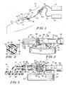
Fig. 1 is a part perspective, part diagrammatic view of the wound care bandage system located on the leg of a patient and coupled to a vent and to vacuum and irrigation sources through the use of a stopcock or a switch valve; -
Fig. 2 is a perspective view of the vent of the system showing a multi-lumen connector for communication with the wound via a multi-lumen tube, a single-lumen connector for communication with the switch valve, and a circular housing holding a filter (in phantom) in communication with the surrounding atmosphere; -
Fig. 3 is a side view of the vent, with portions broken away, showing the multi-lumen connector aligned for coupling to the multi-lumen tube, the single-lumen connector aligned for coupling to a single lumen tube, a passageway of the vent extending between outer lumens of the multi-lumen tube and the filter of the vent, and further showing a thin, flexible wound dressing member of the bandage coupled to the multi-lumen tube by a barbed coupler; -
Fig. 4 is a sectional view of the multi-lumen tube taken along line 4-4 ofFig. 3 showing an inner lumen of the tube for communication with the vacuum source and the irrigation source of the system and four outer lumens of the tube for communication with the filter and surrounding atmosphere to aspirate an area above the wound; -
Fig. 5 is an exploded perspective view of the switch valve and vent of the system showing a vent connector of the valve aligned for coupling to the single-lumen connector of the vent, a vacuum connector for communication with the vacuum source, an irrigation connector for communication with the irrigation source, and a handle or diverter for providing selective communication between the vent connector and either the vacuum source or the irrigation source; -
Figs. 6a and 6b are perspective views of the handle of the switch valve showing a grip and a stem of the handle and further showing a cut-out portion of the stem for selective communication between the vent, vacuum, and irrigation connectors of the switch valve; -
Fig. 7 is a sectional view taken along line 7-7 ofFig. 5 showing the handle of the switch valve in an irrigation position so that the cut-out portion provides a passageway between the irrigation connector and the vent connector to permit fluid from the irrigation source to run through the switch valve to the wound; -
Fig. 8 is a sectional view similar toFig. 7 showing the handle of the switch valve in a vacuum position so that the cut-out portion provides a passageway between the vacuum connector and the vent connector to permit the vacuum source to draw fluid and exudate from the wound; -
Figs. 9-16 illustrate components of another wound care bandage system in accordance with the present disclosure which also provides suction, irrigation, and ventilation to the wound; -
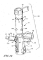
Fig. 9 is a part perspective, part diagrammatic view similar toFig. 1 showing the wound care bandage system ofFigs. 9-16 including a two-level stopcock or switch valve in selective communication with the bandage, vacuum source, and irrigation source of the system, and further showing the two-level stopcock including a vent coupled to a filter; -
Fig. 10 is an exploded view of the two-level stopcock showing an inner barrel or handle and an outer shell, with portions broken away, and further showing the inner barrel having a grip and a stem including an upper level of ports for communication with either the vacuum source or the irrigation source, depending on the position of the inner barrel relative to the outer shell, and a lower level of ports for communication with the vent, and further showing an inner vent groove of the outer shell for providing communication between the outer lumens of the multi-lumen tube and the lower level ports of the barrel; -
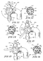
Figs. 11-16 show three positions of the two-level stopcock provided by moving the inner barrel relative to the outer shell to selectively align certain upper level ports of the inner barrel with the vacuum and irrigation connectors of the outer shell and to selectively align certain lower level ports with the vent of the outer shell; -
Figs. 11 and 12 show the two-level stopcock in a vented vacuum position so that the vacuum source and vent are in communication with the wound to create a negative pressure adjacent the wound while drawing air into the system through the vent and over the wound to aspirate the passageways of the system; -
Fig. 11 is a top view of the two-level stopcock in the vented vacuum position showing a passageway (in phantom) connecting the vacuum connector and the multi-lumen tube connector; -
Fig. 12 is a sectional view taken along line 13-13 ofFig. 9 when the two-level stopcock is in the vented vacuum position showing venting passageways of the inner barrel and showing one passageway connecting the vent groove of the outer shell with the vent; -
Figs. 13 and 14 show the two-level stopcock in a vacuum position where only the vacuum source is in communication with the wound to create a negative pressure adjacent the wound; -
Fig. 13 is a top view similar toFig. 11 of the stopcock in the vacuum position after the handle has been turned clockwise from the vented vacuum position shown inFig. 11 , and showing a passageway (in phantom) between the vacuum connector and the multi-lumen tube connector; -
Fig. 14 is a sectional view similar toFig. 12 showing the two-level stopcock in the vacuum position where none of the venting passageways of the inner barrel connect the vent groove of the outer shell with the vent; -
Figs. 15 and 16 show the two-level stopcock in a vented irrigation position where the irrigation source and the vent are in communication with the wound; -
Fig. 15 is a top view similar toFigs. 11 and 13 showing the two-level stopcock in the vented irrigation position after the handle has been turned clockwise from the vacuum position shown inFig. 13 , and showing a passageway (in phantom) between the irrigation connector and the multi-lumen connector; -
Fig. 16 is a sectional view similar toFigs. 12 and 14 showing the two-level stopcock in the vented irrigation position and showing a passageway of the inner barrel connecting the vent groove of the outer shell with the vent; -
Figs. 17-19 show a multi-lumen tube coupler according to the present disclosure for use with either of the systems illustrated inFigs. 1-8 andFigs. 9-16 described above for coupling two multi-lumen tubes together; -
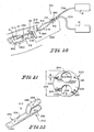
Fig. 17 is a part perspective, part diagrammatic view of the multi-lumen tube coupler in use with the system shown inFigs. 9-16 ; -
Fig. 18 is a perspective view of the multi-lumen tube coupler showing an inner passageway for communication with each inner lumen of the multi-lumen tubes and an outer passageway for communication with each outer lumen of the multi-lumen tubes, and also showing a contoured upper surface and a flat bottom surface of the tube coupler; -
Fig. 19 is a sectional view of the multi-lumen tube coupler coupled to two multi-lumen tubes showing a flow path of fluids through the multi-lumen tubes and the coupler; -
Figs. 20 -28 illustrate components of yet another wound care bandage system in accordance with the present disclosure for providing suction, irrigation, and ventilation to the wound; -
Fig. 20 is a part perspective, part diagrammatic view similar toFig. 1 showing the wound care bandage system ofFigs. 20-28 including a vent coupled to the bandage via a multi-lumen tube (shown inFig. 21 ) and a stopcock or switch valve coupled to the vent (via two single-lumen tubes) to provide selective communication between the bandage and the irrigation and vacuum sources; -
Fig. 21 is an end view of the multi-lumen tube of the system shown inFigs. 20-28 showing the tube including a vacuum lumen, an irrigation lumen, and four outer vent lumens formed within a body of the tube; -
Fig. 22 is a perspective view of a "Y-connecter" of the system shown inFigs. 20-28 for coupling the wound dressing member of the bandage with the multi-lumen tube shown inFig. 21 showing a bandage portion of the connector for insertion within a connector of the member, a vacuum portion for insertion within the vacuum lumen of the multi-lumen tube, and an irrigation portion for insertion within the irrigation lumen of the multi-lumen tube; -
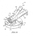
Fig. 23 is a perspective view of the vent of the system shown inFig. 20 showing a multi-lumen connector for coupling with the multi-lumen tube ofFig. 21 , a vacuum connector for communication with the vacuum source via a single-lumen tube, an irrigation connector for communication with the irrigation source via a separate single-lumen tube, and also showing a filter housing coupled to the multi-lumen connector for communication with the venting lumens of the multi-lumen tube and with the atmosphere; -
Fig. 24 is a sectional view of the vent coupled to the multi-lumen tube and the two single-lumen tubes showing a filter of the vent (in phantom), the separate vacuum, irrigation, and vent passageways formed through the vent, and also showing the Y-connecter of the system coupled to the multi-lumen tube and to the member; -
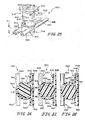
Fig. 25 is an exploded perspective view of the stopcock or switch valve of the system shown inFigs. 20-28 showing two separate passageways through a body of the stopcock for separate communication with the vacuum source and the irrigation source, and showing a handle or diverter, having two cut-out portions, to be received within the body of the stopcock; -
Figs. 26-28 are sectional views showing the stopcock in an irrigation position, a vacuum position, and an off position; -
Fig. 26 is a sectional view of the stopcock showing the stopcock in the vacuum position so that a first cut-out portion of the handle creates a passageway between first and second portions of a vacuum conduit of the stopcock; -
Fig. 27 is a sectional view similar toFig. 26 showing the stopcock in the irrigation position where the handle has been rotated in a clockwise direction from that shown inFig. 26 so that a second cut-out portion (shown in phantom) connects first and second portions of an irrigation conduit with each other; -
Fig. 28 is a sectional view similar toFigs. 26 and 27 showing the stopcock in the off position where the handle has been rotated 180 degrees from that shown inFig. 27 so that neither the first nor the second cut-out portions connect the first and second portions of either of the vacuum conduit or the irrigation conduit; -
Figs. 29-31 illustrate components of still another vacuum bandage system of the present disclosure which provides suction, irrigation, and ventilation to a wound; -
Fig. 29 is a part perspective and part diagrammatic view of a vacuum bandage system of the present disclosure showing a wound dressing member of the bandage including a cover having a port and a wound contacting layer having a wound contacting surface and channels formed in an opposite surface to cooperate with the cover and form passageways of the member in communication with the port and a vacuum source and/or an irrigation source, and also showing a vent line or tube having a first end for communication with the passageways and a second end in communication with the surrounding atmosphere through a filter and a cap; -
Fig. 30 is a sectional view of the bandage ofFig. 29 positioned within a wound and showing a sealing film of the bandage providing a sealed vacuum space above the wound, the first end of the vent line in communication with the vacuum space, and the second end of the vent line coupled to the filter and to the cap outside of the vacuum space; -
Fig. 31 is a sectional view taken along line 31-31 ofFig. 30 showing the vent line and a vacuum tube coupled to each other by a coupler; -
Fig. 32 is a sectional view of an alternative vent line and vacuum tube showing a multi-lumen tube having a vent passageway and a vacuum tube passageway formed therein and separated by a partition; and -
Fig. 33 is a sectional view of yet another vent line and vacuum tube combination showing an outer wall of the vent line and an outer wall of the vacuum tube integrally coupled to one another to form a single multi-lumen tube. - A wound care bandage system is provided which has the capability to create negative pressure adjacent the wound, to irrigate the wound, and to ventilate the wound. A vent of the system is provided to communicate with the wound and with the surrounding atmosphere. In some embodiments, a vent-valve apparatus or a vent and valve combination of the system is in communication with the wound and with a vacuum source and an irrigation source of the wound. The vent-valve apparatus includes the vent which is in communication with the surrounding atmosphere and a diverter to provide selective communication between the wound and the irrigation source or between the wound and the vacuum source, as is described in greater detail below.
- One embodiment of a wound
care bandage system 10 is shown inFigs. 1-8 and is provided to allow a caregiver to create a negative pressure above a wound surface (not shown) of a wound 200 (seeFig. 20 ) through the use of anillustrative vacuum bandage 14 and avacuum source 16, as shown inFig. 1 .System 10 further allows a caregiver to irrigate the wound surface through the use of anirrigation source 18. Additionally,system 10 ventilates the wound during the application of negative pressure to the wound and irrigation of the wound through use of avent 19 in communication with the surrounding atmosphere. - The
system 10 further includes a stopcock or switchvalve 50 coupled to vent 19.Switch valve 50 allows a caregiver to selectively provide communication between the wound and eithervacuum source 16 orirrigation source 18. As is herein defined, the terms switch valve and stopcock are used interchangeably to describe an apparatus for selectively controlling and/or diverting fluid flow therethrough. As shown inFig. 1 , switchvalve 50 is coupled to vent 19 via a single-lumen tube 52. However,switch valve 50 may also be coupled directly to vent 19, as shown inFig. 5 and described in more detail below. Thevent 19 and switch valve 50 (andtube 52, if used) cooperate to create a vent-valve assembly 80 to allow a caregiver to toggle between different modes such as vented vacuum therapy and vented irrigation therapy. Thesystem 10 incorporates two separate fluid lines. One fluid line selectively provides vacuum suction or irrigation to the wound while the other fluid line vents thesystem 10 by providing communication between the wound and the surrounding atmosphere to create air flow above the wound. -
Vacuum bandage 14, as shown inFig. 1 , is provided for use with the wound and is sealed about the wound by a cover or sealingfilm 13 ofbandage 14 to create a sealed environment between the wound and sealingfilm 13 in which a negative pressure can be established.Bandage 14 is selectively coupled to bothvacuum sources 16 andirrigation source 18 through the use ofswitch valve 50, as is described in more detail below. -
Bandage 14 promotes the healing of the wound by providing vacuum therapy to the wound to promote blood flow and remove exudate from the wound surface and by providing for irrigation of the wound with fluids such as saline, for example. An illustrative wound treatment apparatus having a wound temperature control system, a medicine delivery system, and a drainage system is disclosed inU.S. Patent No. 6,458,109 . An illustrative vacuum and irrigation system is disclosed in U.S. Patent Publication No.US 2002/0161317 A1 . Additionally, an illustrative vacuum bandage is disclosed in U.S. Patent Publication No.US 2002/0065494 A1 . Alternative vacuum bandages are disclosed in U.S. Patent Publication No.US 2002/0082567 A1 . Further, a vacuum bandage system including a controller of the system is disclosed inU.S. Patent Application No. 10/159,583 filed on May 31, 2002 US Patent Application No. 10/159,720 filed on May 31, 2002 - As mentioned above,
system 10 incorporates two separate fluid lines to provide vented vacuum therapy and vented irrigation therapy to the wound. Venting ofbandage 14 is disclosed inU.S. Patent Application Serial No. 60/344,588 filed on December 26, 2001
Venting provides for increased air flow throughbandage 14 and above or adjacent the wound whilevacuum source 16 applies suction to the wound.System 10 is also vented whileirrigation source 18 provides fluid to the wound. Without providing for ventilation of thesystem 10 during operation ofvacuum source 16, a generally closed system is created betweenvacuum bandage 14 andvacuum source 16. For example, in bandages without a ventilation system, once the requisite amount of air has been removed by thevacuum source 16 to create a predetermined negative pressure at the wound surface, it is possible for the system to become generally static, inhibiting much, if any, fluid flow from the wound surface. In some embodiments disclosed herein, static conditions may be created at the wound surface. - Ventilation of the
system 10, while drawing a negative pressure over the wound, acts to prevent thesystem 10 from becoming static by drawing air in from the surrounding atmosphere throughvent 19, tobandage 14 to create air flow above the wound, and out through a vacuum tube in communication withvacuum source 14. Therefore, venting thesystem 10 increases air flow above the wound whilevacuum source 16 applies suction to the wound. - The two fluid lines for ventilation and vacuum/irrigation of the wound are provided in
multi-lumen tube 20, shown in cross-section inFig. 4 . As shown inFig. 3 ,tube 20 is coupled to aconnector 15 ofbandage 14, and is therefore in communication with the wound at oneend 21 and is coupled to vent 19 at theother end 23.Tube 20 includes aninner lumen 22 for selective communication with thevacuum source 16 and theirrigation source 18 andouter lumens 24 formed in a body orouter wall 25 oftube 20 for communication with the surrounding atmosphere throughvent 19.Inner lumen 22 thus defines a portion of a vacuum/irrigation passageway 42 andouter lumens 24 each define a portion of aventilation passageway 44. - As shown in
Fig. 4 ,tube 20 includes fourouter lumens 24 spaced aboutinner lumen 22. It is within the scope of this disclosure, however, to include a multi-lumen tube having one or more outer lumens in communication with the surrounding atmosphere and one or more inner lumens in selective communication with thevacuum source 16 and theirrigation source 18. Illustratively, theouter diameter 26 oftube 20 is 0.250 inch (6.300 mm), theinner diameter 28 of tube 20 (the diameter of inner lumen 22) is 0.125 inch (3.150 mm), and thediameter 29 of each outer or peripheral lumen is 0.014 inch (0.353 mm). Althoughtube 20 includes the above dimensions, it is within the scope of this disclosure to provide any suitable multi-lumen tube having lumens of any suitable size. - As shown in
Fig. 3 ,bandage 14 illustratively includes a thin, flexiblewound dressing member 12 havingconnector 15 coupled totube 20 by a barbed tube coupler 11.Member 12 lies adjacent to and generally conforms to the wound surface. Sealingfilm 13 is placed overmember 12 and sealed aroundtube 20 to the patient'shealthy skin 27 surrounding the wound, as shown inFig. 1 . Illustratively,connector 15 is in communication with the wound by a plurality ofpassageways 66 ofmember 12 and a plurality ofholes 67, each in communication with one of thepassageways 66, formed in abottom surface 68 ofmember 19. Tube coupler 11 connectsinner lumen 22 oftube 20 withconnector 15. Eachouter lumen 24 is open at anend 21 oftube 20. This allows air to be drawn in from the atmosphere throughvent 19, to flow throughouter lumens 24 andexit tube 20 atend 21, to circulate aroundmember 12 to the wound surface, and to flow through theholes 67 andpassageways 66 ofmember 12 into a vacuum/irrigation passageway 42 formed in part bylumen 22. The negative pressure created byvacuum source 16 causes air to flow throughsystem 10 in this manner. - Although
bandage 14 is described above, it is within the scope of this disclosure for thesystem 10, and other alternative systems described below, to include any suitable bandage or wound dressing member coupled to thevacuum source 16 to communicate negative pressure from thevacuum source 16 to the wound.Bandage 14, therefore, is merely an illustrative bandage of the wound care bandage systems disclosed herein. - As mentioned above,
system 10 further includesvent 19.Vent 19 is coupled to end 23 oftube 20, as shown inFig. 1 , and is illustratively shown to be coupled to patient'shealthy skin 27 bytape 94, for example. As shown inFigs. 2 and 3 , vent 19 includes a multi-lumen or woundconnector 30 for coupling withmulti-lumen tube 20 and a single-lumen connector 32 for coupling with single-lumen tube 52 or for coupling directly to switchvalve 50, as shown inFig. 5 .Vent 19 further includes afilter 34, shown in phantom inFigs. 2 and 3 , housed within afilter housing 40.Multi-lumen connector 30 includes aninner conduit 36 and anouter conduit 38 concentric and coaxial withinner conduit 36 along anaxis 39, as shown inFig. 3 . Anedge 41 ofinner conduit 36 is substantially coplanar with anedge 43 ofouter conduit 38. Anannular space 45 is defined between a cylindricalinner surface 47 ofouter conduit 38 and a cylindricalouter surface 53 ofinner conduit 36. -
Inner conduit 36 is in communication withvacuum source 16 andirrigation source 18 throughstopcock 50 and defines a portion of the vacuum/irrigation passageway 42. The vacuum/irrigation passageway 42 extends throughinner lumen 22, a portion ofvent 19 andstopcock 50.Outer conduit 38, orannular space 45, is in communication with the surrounding atmosphere and defines a portion ofvent passageway 44. Thevent passageway 44 extends throughouter lumens 24 and a portion ofvent 19 to the surrounding atmosphere. - As shown in
Fig. 3 , a ridge or stop 59 is coupled toinner surface 47 ofouter conduit 38 to preventtube 20 from being inserted too far withinconnector 30 and thus sealing offouter lumens 24.Stop 59 preventsvent passageway 44 from becoming closed off and keepsvent passageway 44 open to receive air from the surrounding atmosphere.Vent 19 includes three evenly spaced stops 59 coupled toinner surface 47. It is within the scope of this disclosure, however, to include a vent having any number ofstops 59 or the like to preventvent passageway 44 from becoming closed off. - When connecting
multi-lumen tube 20 withvent 19,inner conduit 36 is received withininner lumen 22 oftube 20.Wall 25 oftube 20, which includesouter lumens 24, is received withinannular space 45 ofconnecter 30.Tube 20 is, therefore, press fit intoconnector 30 and, if desired, may be permanently coupled toconnecter 30 through the use of adhesives applied to the appropriate surfaces ofconnecter 30 and/ortube 20. -
Connector 32 is received within single-lumen tube 52 when connectingvent 19 totube 52.Tube 52 is press fit ontoconnector 32 so that anend 65 of single-lumen tube 52 abuts anannular shoulder surface 69 ofconduit 30. As noted above, vent 19 may also be coupled directly to switchvalve 50 through the use of a luer lock connection shown inFig. 5 and discussed further below. - As shown in
Fig. 3 , vent 19 includes an opening orpassageway 46 leading betweenouter conduit 38 andfilter 34 to connectannular space 45 with the surrounding atmosphere.Opening 46 extends radially away fromconduit 30 and is generally perpendicular toaxis 39.Opening 46 is defined bycylindrical wall 27. Illustratively, opening 46 has a diameter of 0.100 inch (2.54 mm), however, it is within the scope of this disclosure to include a vent having any suitably sized opening for receiving air from the surrounding atmosphere. - Further illustratively,
filter 34, is a 0.2 micron anti-microbial filter for preventing bacteria and other microorganisms in the atmosphere from entering thevent 19 and traveling alongvent passageway 44 below sealingfilm 13 ofbandage 14 to the wound. Such an air filter, for example, is made by W.L. Gore & Associates, Inc. of Elkton, MD. As mentioned above,filter 34 is housed withinhousing 40.Housing 40 has a circulartop wall 31, acylindrical sidewall 33, and a circular bottom wall (not shown).Filter 34 is a generally circular dish of material sandwiched betweentop wall 31 and the bottom wall. The bottom wall has apertures, openings, or the like so thatfilter 34 is in communication with the surrounding atmosphere. Further, the bottom wall is removable so thatfilter 34 may be replaced if needed.Vent 19 further includesreinforcement ribs 35 appended totop wall 31 ofhousing 40 andwall 27 definingpassageway 46. - In operation, vent 19 is used during both vacuum and irrigation modes of the system. As mentioned before, vent 19 provides increased air flow through
bandage 14 and above the wound.Vent 19 also creates an open system and prevents the system from becoming static. The air flow path while vacuuming the system begins as air is drawn in from the surrounding atmosphere intofilter housing 40 ofvent 19 and throughfilter 34. The air then travels through opening 46 intoannular space 45 defined byouter conduit 38 and throughouter lumens 24 ofmulti-lumen tube 20. The air travels through theouter lumens 24 fromvent end 23 oftube 20 to end 21 oftube 20, a portion of which is positioned under sealingfilm 13, to communicate with the wound. Vacuumsource 16 then draws the air aroundwound dressing member 12 throughpassageways 66 at an open peripheral edge ofmember 12 and throughholes 67 intopassageways 66. Air is then drawn frompassageways 66 intoconnector 15 ofmember 12, through barb 11, and throughinner lumen 22 ofmulti-lumen tube 20 towardvacuum source 14. - It is also within the scope of the disclosure for the caregiver to close off
vent 19 while vacuuming or irrigating the wound.Vent 19 may be closed in a number of ways. For example, a cap or valve (not shown) may be coupled to filter 34 or filterhousing 40 to prevent air flow throughfilter 40. It is within the scope of this disclosure to include a vent having other suitable means of preventing air flow therethrough. - As shown in
Fig. 3 and mentioned above,inner conduit 36 andouter conduit 38 form separate passageways throughvent 19.Inner conduit 36 is in communication with and forms a portion of vacuum/irrigation passageway 42 which extends throughinner lumen 22, a portion ofvent 19 and on to switchvalve 50.Outer conduit 38 is in communication with and forms a portion ofvent passageway 44, which extends throughouter lumens 24 and a portion ofvent 19.Vent passageway 44 is in communication with the atmosphere throughfilter 34. - As shown in
Fig. 1 ,system 10 further includesswitch valve 50.Switch valve 50 is positioned betweenvent 19 and vacuum andirrigation sources lumen tube 52 is coupled to and extends between single-lumen connector 32 ofvent 19 andswitch valve 50 and forms a portion of vacuum/irrigation passageway 42.Switch valve 50, includes avent connector 54 which can be coupled either to single-lumen tube 52, as shown inFig. 1 , or directly toconnecter 32 ofvent 19, as shown inFig. 5 , through the use of a luer lock. Single-lumen connector 32 includes afemale thread portion 55 of the luer lock, and ventconnector 54 ofswitch valve 50 includes amale portion 57 of the luer lock so that the two can be coupled together. - As shown in
Fig. 5 , switchvalve 50 includes abody 60 and a handle ordiverter 51 coupled tobody 60.Body 60 includesvent connector 54, avacuum connector 56 in communication withvacuum source 16, and anirrigation connector 58 in communication withirrigation source 18.Vent connector 54 forms another portion of vacuum/irrigation passageway 42 and is in selective communication withvacuum source 16 andirrigation source 18. Vacuum/irrigation passageway 42 therefore extends fromend 21 ofinner lumen 22 ofmulti-lumen tube 20 tomulti-lumen connector 30 ofvent 19, throughinner conduit 36 ofvent 19, outconnector 32 ofvent 19, to ventconnector 54 ofswitch valve 50 and partially throughswitch valve 50 to diverter 51 ofswitch valve 50. -
Switch valve 50 includesdiverter 51 for selectively providing communication betweenvacuum source 16 andbandage 14 and betweenirrigation source 18 andbandage 14.Diverter 51 includes agrip 62 and astem 64 coupled togrip 62, as show inFigs. 6a and 6b .Diverter 51 is rotatably movable relative tobody 60 to selectively provide communication between eithervent connector 54 andirrigation connector 58 or betweenvent connector 54 andvacuum connector 56. A caregiver rotatesdiverter 51 between an irrigation position shown inFig. 7 and a vacuum position shown inFig. 8 depending on whether the wound is to receive vacuum or irrigation treatment, respectively.Switch valve 50 allows the caregiver to easily switch between communication withvacuum source 16 andirrigation source 18 without the need to disconnect or reconnect various tubes from each of thevacuum source 16 and/orirrigation source 18, for example. - As shown in
Figs. 7 and 8 ,body 60 includes anaperture 61 for receivingstem 64 ofdiverter 51.Vent connector 54,vacuum connector 56, andirrigation connector 58 each form arespective opening aperture 61. Asdiverter 51 is rotated, a cut-outportion 63 ofstem 64 provides a passageway betweenvent connector 54 andvacuum connector 56 whendiverter 51 is in the vacuum position, for example. Whendiverter 51 is in the irrigation position, cut-outportion 63 provides a passageway betweenvent connector 54 andirrigation connector 64.Diverter 51 is also movable to an off position where cut-outportion 63 does not provide any communication between theconnectors - In addition to vacuum/
irrigation passageway 42 and ventpassageway 44,system 10 further includes aseparate vacuum passageway 70 and aseparate irrigation passageway 72.Vacuum connector 56 defines a portion ofvacuum passageway 70 andirrigation connector 58 defines a portion ofirrigation passageway 72. As shown inFig. 1 ,vacuum connector 56 is coupled to avacuum tube 74 which is, in turn, coupled tovacuum source 16. Thevacuum passageway 70, therefore, extends from opening 84 ofbody 60 throughvacuum connector 56 andvacuum tube 74 to vacuumsource 16. - As shown in
Fig. 1 ,irrigation connector 58 is coupled to anirrigation tube 76 which is, in turn, coupled toirrigation source 18. Theirrigation passageway 72, therefore, extends from opening 86 ofbody 60 throughirrigation connector 58 andirrigation tube 76 toirrigation source 18. Thus, at opening 82 ofbody 60, vacuum/irrigation passageway 42 ends and is split into separate vacuum andirrigation passageways - As shown in
Fig. 5 , anattachment 88 is coupled toirrigation connector 58.Attachment 88 includes afirst inlet 90 for communication withirrigation tube 76 andirrigation source 18 and asecond inlet 92 for communication with a hand-held syringe (not shown).Attachment 88 provides two means of introducing fluids intosystem 10.Second inlet 92 allows a caregiver to manually introduce fluids intosystem 10 whileirrigation source 18 includes automatic controls for introducing fluids intosystem 10 throughfirst inlet 90. Aslot 96 ofirrigation connector 58 receives a portion ofsecond inlet 92 to secureattachment 88 withinirrigation connector 58. - As mentioned above,
system 10 allows a caregiver to treat the wound using vented vacuum therapy through the use ofvent 19 withvacuum source 16 and using vented irrigation therapy through the use ofirrigation source 18 andvent 19. To provide vented vacuum therapy to the wound, the caregiver movesdiverter 51 to the vacuum position, shown inFig. 8 , so that cut-outportion 63 ofstem 64 connects opening 82 ofvent connector 54 with opening 84 ofvacuum connector 56. Therefore,irrigation connector 58 andirrigation passageway 72 are closed off and vacuum/irrigation passageway 42 is connected withvacuum connector 56 andvacuum passageway 70.Vent passageway 44 is kept open to the surrounding atmosphere. The negative pressure provided byvacuum source 16 abovewound 12 acts to draw air in from the atmosphere throughfilter 34 ofvent 19 andouter lumens 24. As mentioned above, vent 19 is provided to aspirate thesystem 10 by creating an air flow path from the atmosphere to thebandage 14, over the wound, and out throughinner lumen 22 in communication withvacuum source 16. - To create vented irrigation of
wound 12, a caregiver movesdiverter 51 to the irrigation position so that cut-outportion 63 ofstem 64 connects opening 82 ofvent connector 54 with opening 56 ofirrigation connector 58. Therefore,irrigation passageway 72 of theirrigation connector 58 is in communication with the vacuum/irrigation passageway 42 of thevent connector 54. Thevacuum passageway 70 is thus cut off from communication with the vacuum/irrigation passageway 42. Irrigation fluid is then dispensed fromirrigation source 18 throughirrigation passageway 72 oftube 76 andswitch valve 50 to the vacuum/irrigation passageway 42 throughvent connector 54,tube 52, vent 19, andinner lumen 22 ofmulti-lumen tube 20 to wound 12.Vent 19 is left in an open position to allow air to flow out ofbandage 14 while fluid fromirrigation source 18 is channeled to the wound. As mentioned above, it is also within the scope of this disclosure to provide non-vented irrigation of the wound by closing off vent 19 from the surrounding atmosphere while providing fluid to the wound throughirrigation source 18. - As mentioned above, the combination of
vent 19, and switchvalve 50 is defined as vent-valve assembly 80. If desired,assembly 80 may also includetube 52 or another conduit or passageway betweenvent 19 andswitch valve 50.Assembly 80 provides a caregiver with the ability to toggle or selectively switch between the vented vacuum mode of therapy and the vented irrigation mode of therapy for the treatment of the wound. As mentioned above, it is within the scope of this disclosure to include a vent which is able to be closed off from communication with the surrounding atmosphere so that vacuum only and/or irrigation only therapy may be provided as well. - An alternative vent-
valve assembly 180 is provided for use withsystem 10, as shown inFigs. 9-16 .Assembly 180 includes a stopcock or valve portion in selective communication withvacuum source 16 andirrigation source 18 and a vent portion in communication with the surrounding atmosphere.Assembly 180 is configured to selectively provide three modes of therapy: vacuum therapy, vented vacuum therapy, and vented irrigation therapy. - As shown in
Fig. 9 , vent-valve assembly 180 is positioned betweenillustrative bandage 14 ofsystem 10 and vacuum andirrigation sources Assembly 180 serves a similar function asassembly 80, includingvent 19 andstopcock 50, shown inFigs. 1-8 . Similar toassembly 80,assembly 180 is in communication withbandage 14,vacuum source 16, andirrigation source 18 ofsystem 10.Assembly 180 is operated by a caregiver during the treatment of a patient to change from mode to mode as desired. - As shown in
Fig. 10 ,assembly 180 includes an outer shell orbody 110 and a diverter orinner barrel 112.Inner barrel 112 is normally positioned withinouter shell 110, as shown inFig. 9 , and is rotatable relative toouter shell 110 between three different positions which correlate with the three available modes: vacuum, vented vacuum, vented irrigation.Outer shell 110 includes acylindrical hub 114 having anouter surface 116 and ininner surface 118, shown inFig. 10 .Outer shell 110 further includes a multi-lumen orwound connector 130, avent 119, avacuum connector 156, and anirrigation connector 158. Suitable coupling means such as a C-clip (not shown) to fit aroundinner barrel 112, a pin (not shown) throughouter shell 110 andinner barrel 112, for example, are provided to prevent inner barrel ordiverter 112 from being inadvertently separated frombody 110. Such coupling means are also provided for use withstopcocks 50 and 250 (discussed below) to prevent the handle of each from being inadvertently decoupled from the body of each. - Similar to
multi-lumen connector 30 ofvent 19,multi-lumen connector 130 ofassembly 180 includesinner conduit 36 andouter conduit 38 spaced apart from and concentric withinner conduit 36.Inner conduit 36 defines a portion of vacuum/irrigation passageway 42 andouter conduit 38 defines a portion ofvent passageway 44 ofsystem 10.Inner conduit 36 is received withininner lumen 22 oftube 20.Wall 25 oftube 20, which includesouter lumens 24, is received withinouter conduit 38 ofmulti-lumen connector 130. As shown inFig. 9 ,inner conduit 36 is coupled to abarb 37.Barb 37 is received withininner lumen 22 as well and helps maintain the connection betweentube 20 andmulti-lumen connector 130. It is within the scope of this disclosure formulti-lumen connector 30 ofvent 19 to havebarb 37 formed integrally withinner conduit 36. - As shown in
Fig. 10 ,outer conduit 38 includes apartition 48 having multiple vent holes 49 formed therethrough. Air traveling throughlumens 24 also travels through theholes 49 to avent grove 122 formed ininner surface 118 ofhub 114. It is not necessary forouter lumens 24 oftube 20 to align directly with one of the vent holes 49. A stop (not shown), similar to stop 59, is coupled toinner surface 47 ofouter conduit 38 to preventtube 20 from being inserted too far withinconnecter 130.Vent groove 122 connectsouter conduit 38 withvent 119, as is described in more detail below. -
Vacuum connector 156 communicates withvacuum source 16 throughvacuum tube 74.Vacuum connector 156 includesbarb 37 received withintube 74.Vacuum connector 156 andvacuum tube 74form vacuum passageway 70 ofsystem 10.Irrigation connector 158 communicates withirrigation source 18 throughirrigation tube 76, as shown inFig. 17 .Irrigation connector 158 andirrigation tube 76 form theirrigation passageway 72 ofsystem 10.Vacuum connector 156 andirrigation connector 158 are each in selective communication withmulti-lumen connector 130, as is described below. As shown inFig. 9 ,air filter 34, contained within ahousing 124, is coupled to vent 119 and is received within an aperture 120 (shown inFig. 10 ) ofvent 119.Housing 124 includes anair inlet tube 126 and aconnector tube 128 coupled to vent 119 and in communication withaperture 120 ofvent 119. -
Diverter 112, as shown inFig. 10 , includes agrip 162 and a cylinder or stem 164 coupled togrip 162.Cylinder 164 includes an upper level of holes and a lower level of holes, as shown inFig. 10 . As shown in phantom inFigs. 11, 13, and 15 , the upper level of holes includes first, second, third, fourth, andfifth holes Figs. 12, 14, and 16 , the lower level of holes includes first, second, third, andfourth holes inner conduit 36 ofmulti-lumen connector 130 and with each of the vacuum andirrigation connectors outer conduit 38 andaperture 120 ofvent 119. The upper holes ofcylinder 164 form interconnecting passageways throughcylinder 164 to selectively connectinner conduit 36 withvacuum conduit 156 andirrigation conduit 158 and the lower holes form passageways throughcylinder 164 to selectively connectouter conduit 38 withvent 119, as is described in more detail below. - As shown in
Figs. 11 and 12 ,assembly 180 is in the vented vacuum position. As shown inFig. 11 , the upper holes are positioned so thathole 166 is in communication withinner conduit 36 andhole 170 is in communication withvacuum connector 156 to provide a passageway betweeninner conduit 36 andvacuum connector 156. Theother holes connectors outer shell 110. Looking now to the lower level of holes shown inFig. 12 ,hole 182 is in communication withvent groove 122 andhole 186 is in communication withaperture 120 ofvent 119 to provide a passageway betweenvent groove 122 and vent 119 so thatouter lumens 24 oftube 20 are in communication with the surrounding atmosphere. - By rotating
grip 162 clockwise (as viewed from the top of apparatus 180), a caregiver rotatesinner barrel 112 relative toouter shell 110 to move assembly 180 to the vacuum position shown inFigs. 13 and 14 . In the vacuum position,upper level hole 174 is in communication withinner conduit 36 ofmulti-lumen connector 130 andhole 168 is in communication withvacuum connector 156 to provide a passageway betweeninner conduit 36 andvacuum connector 156. In the vacuum position, however, ventpassageway 44 ofsystem 10 is prevented from communicating with the surrounding atmosphere throughvent 119. As shown inFig. 14 , for example, none of the lower level holes are in communication with eithervent groove 122 oraperture 120 ofvent 119. - By rotating
grip 162 still further clockwise, a caregiver rotatesinner barrel 112 relative toouter shell 110 to move assembly 180 to the vented irrigation position shown inFigs. 15 and 16. Fig. 15 shows the orientation of the upper level holes of theinner barrel 112 whileassembly 180 is in the vented irrigation position.Hole 172 is in communication withinner conduit 36 ofmulti-lumen connector 130 andhole 166 is in communication withirrigation connector 158 to provide communication betweeninner conduit 36 andirrigation connector 158.Fig. 16 shows the orientation of the lower level holes whenstopcock 180 is in the vented irrigation position.Hole 188 is in communication withvent groove 122 andhole 184 is in communication withaperture 120 ofvent 119 so thatouter conduit 38 is in communication withvent 119 to allow air from the surrounding atmosphere to entersystem 10. It is also within the scope of this disclosure forassembly 180 to be in an "off" position where none of the upper level passageways connect any of theconnecters vent grove 122 with thevent 119. - Referring now to
Figs. 17-19 , atube coupler 140 is provided for use withsystem 10. As shown inFig. 17 ,coupler 140 is positioned betweenbandage 14 andassembly 180. It is within the scope of this disclosure, however, to position a tube coupler betweenbandage 14 andassembly 80 shown inFig. 1 .Coupler 140 connects or couples two multi-lumen tubes together.Coupler 140 allows a caregiver to disconnect a portion ofsystem 10 betweenbandage 14 andassemblies Figs. 17-19 ,coupler 140couples multi-lumen tube 20 to anothermulti-lumen tube 17. -
Coupler 140 includes anouter body 142 having a curvedupper surface 144 and a generally flatbottom surface 146.Outer body 142 defines apassageway 148 therethrough for receiving a portion of a multi-lumen tube at afirst end 136 and at asecond end 138.Passageway 148 is defined by aninner surface 149 ofbody 142.Coupler 140 further includes aninner conduit 150 which defines a portion of vacuum/irrigation passageway 42.Inner conduit 150 is positioned withinpassageway 148. A portion ofvent passageway 44 is annular and is defined betweeninner surface 149 ofbody 142 and anouter surface 151 ofinner conduit 150.Coupler 140 further includes acentral partition 152 formed aroundconduit 150 and connected toinner surface 149.Partition 152 includes three generally evenly spacedholes 154 for the vented air to flow through. - An end of
tube 20 is inserted intofirst end 136 ofcoupler 140 and an end oftube 17 is inserted intosecond end 138 ofcoupler 140, as shown inFig. 19 , so thatinner conduit 150 is received within theinner lumen 22 of eachtube multi-lumen tubes outer lumens 24 formed inwall 25. As shown inFig. 19 ,tubes coupler 140 and are generally spaced-apart frompartition 152 so that air flowing through the fourouter lumens 24 oftube 17 flows into anopen space 155 on the right side ofpartition 152, as shown inFig. 19 , throughholes 154 ofpartition 152 and into anopen space 157 located on the left side ofpartition 152 intoouter lumens 24 oftube 20. -
Tube coupler 140 may also be used to aide in effectively securing sealingfilm 13 ofbandage 14 over or aroundtube 20. For example,coupler 140 may be placed on the patient's healthy skin adjacent the wound. Thefilm 13 may then be placed over curvedupper surface 144 ofcoupler 140 and effect a seal aroundcoupler 140 to create a sealed environment betweenfilm 13 and the wound.Coupler 140, therefore, may also act to prevent leaks in the vacuum space created belowfilm 13.Coupler 140 further includes a ridge or stop 153 coupled toinner surface 149 to each of the right and left sides ofpartition 152 to prevent eachrespective tube partition 152 and closing offvent lumens 24 from communication with the surrounding atmosphere. Eachopen space respective stop 153 andpartition 152, as shown inFig. 19 . - Referring now to
Figs. 20-28 , another illustrative woundcare bandage system 210 is provided.System 210 operates similarly tosystem 10 described above and includes a vent-valve apparatus 280 to provide ventilation while allowing a user to toggle between a vacuum therapy mode and an irrigation therapy mode. As shown inFig. 20 ,bandage 14 is coupled to avent 219 via an alternativemulti-lumen tube 220. Specifically,member 12 ofbandage 14 is coupled to a "Y-connector" 212 of thesystem 210 which is coupled totube 220. Y-connector 212 is shown in more detail inFigs. 22 and24 and is discussed in more detail below. - Vent-
valve apparatus 280 includes a stopcock or switchvalve 250 coupled to vent 219 via two single-lumen tubes Switch valve 250 is coupled to bothvacuum source 16 andirrigation source 18 to provide selective communication between either thebandage 14 andvacuum source 16 or betweenbandage 14 andirrigation source 18, as described below. -
Vent 219, similar to vent 19, is spaced apart frombandage 14 and is illustratively shown to be coupled to patient'shealthy skin 27 bytape 94, for example.Vent 219 is able to provide ventilation to wound 200 (shown inFig. 20 ) during the application of negative pressure to wound 200 and during irrigation ofwound 200 becausevent 219, similar tovents wound 200. - The wound
care bandage system 210 shown inFigs. 20-28 incorporates three separate fluid paths. One fluid path is used exclusively for the purpose of venting thewound 200 with air from the surrounding atmosphere. A second fluid path is used to create a negative pressure adjacent thewound 200, while the third fluid path is used to irrigate thewound 200.Switch valve 250 acts to selectively communicate either the vacuum path or the irrigation path with the wound 200: The three fluid paths for ventilation, vacuum, and irrigation ofwound 200 are provided bymulti-lumen tube 220. -
Multi-lumen tube 220 includes avacuum lumen 222, anirrigation lumen 224, and four outer ventinglumens 226 formed within and defined by abody 228, as shown inFig. 21 .Vacuum lumen 222 is in communication withvacuum source 16,irrigation lumen 224 is in communication withirrigation source 18, and eachventing lumen 226 is in communication with the atmosphere throughvent 219, as is described below. As shown inFigs. 20 and24 ,multi-lumen tube 220 is coupled to analternative connector 214 ofmember 12 by Y-connecter 212, and is therefore in communication with thewound 200 at oneend 230 and is coupled to vent 260 at anotherend 232. - Although
tube 200 is shown to include four ventinglumens 214, it is within the scope of this disclosure to include a multi-lumen tube having one or more venting lumens in communication with the surrounding atmosphere, one or more vacuum lumens in communication with thevacuum source 16, and one or more irrigation lumens in communication with theirrigation source 18. Illustratively, anouter diameter 234 oftube 220 is 0.375 inch (9.53 mm), adiameter 236 ofvacuum lumen 222 is 0.125 inch (3.175 mm), a diameter 238 ofirrigation lumen 224 is 0.125 inch (3.175 mm), and adiameter 240 of eachouter venting lumen 226 is 0.020 inch (0.508 mm). Althoughtube 220 includes the above dimensions, it is within the scope of this disclosure to provide any suitable multi-lumen tube having lumens of any suitable size. - As mentioned above, Y-
connecter 212 is provided for coupling withalternative connector 214 ofvacuum bandage 14.Connector 214 is similar toconnector 15 and is in communication withwound 200 throughchannels 66 and holes 67 ofmember 12.Connector 214 is different fromconnector 15 in thatconnector 214 is positioned at an angle relative to atop surface 242 ofmember 12 and includes a single angled passageway 244 (as shown inFig. 24 ) rather than a vertical passageway connected to a horizontal passageway of connector 15 (as shown inFig. 3 ). In the illustrative embodiment, the included angle between an axis alongpassageway 244 and thetop surface 242 ofmember 12, whenmember 12 is in a flat configuration, is about 30 degrees. - Illustratively, Y-
connecter 212 includes abandage portion 246, anirrigation portion 248, and avacuum portion 252, as shown inFig. 22 .Irrigation portion 248 includes apassageway 254 forming a section of the irrigation passageway,vacuum portion 252 includes apassageway 256 forming a section of the vacuum passageway, andbandage portion 246 includes apassageway 258 forming a section of the vacuum/irrigation passageway. Thepassageway 254 ofirrigation portion 248 and thepassageway 256 ofvacuum portion 252 each merge intopassageway 258 of thebandage portion 246. Oncebandage portion 246 of Y-connecter 212 splits into theirrigation portion 248 and thevacuum portion 252, the irrigation and vacuum passageways remain separate and distinct passageways throughmulti-lumen tube 220, vent 219, and switchvalve 250 to therespective irrigation source 18 andvacuum source 16. -
Bandage portion 246 is press fit intoconnector 214, as shown inFig. 24 , and includes anangled end 260 to lie adjacent to thetop surface 242 ofmember 12.Irrigation portion 248 is similarly press fit intoirrigation lumen 224 oftube 220 andvacuum portion 252 is press fit intovacuum lumen 222 oftube 220. In some embodiments, adhesive or sealant is applied to either or all ofportions bandage portion 246 andconnector 214 betweenirrigation portion 248 andtube 220, and betweenvacuum portion 252 andtube 220. Y-connecter 212 is provided to connectbandage 14 withmulti-lumen tube 220 and vent 219. - Referring now to
Fig. 23 ,vent 219 includes amulti-lumen connector 262 for coupling withmulti-lumen tube 220, a single-lumen vacuum connector 264 for coupling with a single-lumen tube, such astube 216, and a single-lumen irrigation connector 266 for coupling with a single-lumen tube, such as tube 218 (as shown inFig. 20 ).Tubes valve 250 as shown inFig. 20 and described in more detail below. It is also within the scope of this disclosure to eliminate the use oftubes vent 219 is coupled directly to switchvalve 250. Similar tovents filter housing 40, in communication withmulti-lumen connector 262. -
Multi-lumen connector 262 includes anouter conduit 272, aninner vacuum conduit 274, and aninner irrigation conduit 276, as shown inFig. 23 . Bothvacuum conduit 274 andirrigation conduit 276 are located withinouter conduit 272. Anedge 278 ofouter conduit 272 is substantially coplanar with anedge 281 ofvacuum conduit 274 and anedge 282 ofirrigation conduit 276.Vacuum conduit 274 is in communication withvacuum source 16 throughswitch valve 250 and defines a portion of the vacuum passageway.Irrigation conduit 276 is in communication with theirrigation source 18 throughswitch valve 250 and defines a portion of the irrigation passageway.Outer conduit 252 is in communication with the surrounding atmosphere and defines a portion of the vent passageway. - As shown in
Fig. 24 ,vacuum conduit 274 is received withinvacuum lumen 222 oftube 220.Body 228 oftube 220, which includes outer ventinglumens 226, is received within aspace 284 defined between a cylindricalinner surface 286 ofouter conduit 272 and cylindricalouter surfaces irrigation conduits Fig. 23 ).Tube 220 is press fit into thespace 284 so that the outer surface oftube 220 abuts cylindricalinner surface 286 ofouter conduit 272, so that an inner surface ofvacuum lumen 220 abuts the cylindricalouter surface 288 of thevacuum conduit 274, and so that the inner surface ofirrigation lumen 224 abuts the cylindricalouter surface 290 of theirrigation conduit 276. In some embodiments, an adhesive material or sealant is applied to the appropriate surfaces oftube 220 andmulti-lumen connector 262 to enhance the connection betweentube 220 and vent 219. - As shown in
Fig. 23 , a ridge or stop (not shown) is coupled to and positioned betweenouter surface 288 ofvacuum conduit 274 andouter surface 290 ofirrigation conduit 276 to preventtube 220 from being inserted too far withinconnector 262 and thus sealing offouter lumens 226. The stop prevents vent passageway from becoming closed off and keeps vent passageway open to receive air from the surrounding atmosphere. Illustratively, vent 219 includes one stop, however, it is within the scope of this disclosure to include a vent having any number of stops or the like to prevent the vent passageway from becoming closed off from the surrounding atmosphere. -
Vacuum connector 264 ofvent 219 includes aninner surface 292 defining a portion of the vacuum passageway and anouter surface 294.Vacuum connector 264 is in communication withvacuum conduit 274 ofmulti-lumen connector 262, as shown in phantom inFigs. 23 and24 . Illustratively, single-lumen tube 216, coupled tovacuum source 16, is press fit intovacuum connector 264, as shown inFig. 24 .Tube 216 may further be permanently or temporarily bonded tovacuum connecter 264 through the use of an adhesive material applied to the appropriate surfaces oftube 216 andconnecter 264. -
Irrigation connector 266 ofvent 219 similarly includes aninner surface 296 defining a portion of the irrigation passageway and anouter surface 298 including ashoulder 300.Irrigation connector 266 is in communication withirrigation conduit 276 ofmulti-lumen connector 262, also shown inFigs. 23 and24 . Illustratively, single-lumen tube 218 is press-fit intoirrigation connector 266, as shown inFig. 24 .Tube 218 may further be permanently or temporarily bonded toirrigation connector 266 through the use of an adhesive material applied to the appropriate surfaces oftube 218 andconnector 266. It is within the scope of this disclosure, however, to connecttubes vacuum connectors -
Outer conduit 272 ofmulti-lumen connector 262 further includes an opening oraperture 302 in communication with the surrounding atmosphere.Housing 40 forfilter 34 is coupled tomulti-lumen connector 262 so that apassageway 46 ofhousing 40 connectsspace 284 with thefilter 34 and the surrounding atmosphere.Passageway 46 extends radially away fromouter conduit 272 and is generally perpendicular to an axis running throughvacuum conduit 274.Passageway 46 is defined bycylindrical wall 27. - In operation, vent 219 is used during both vacuum and irrigation modes of the system. As mentioned before with respect to
vents bandage 14 and abovewound 200. Vent 219 also creates an open system and prevents the system from becoming static. Vent 219 further maintains separate vacuum and irrigation passageways. As mentioned before with respect tovents wound 200. Vent 219 may also be closed in a number of ways. For example, a cap or a valve (not shown) may be coupled to filter 34 or filterhousing 40 to prevent air flow throughfilter 34. It is within the scope of this disclosure to include a vent having other suitable means of preventing air flow therethrough. - Referring now to
Figs. 25-28 , thestopcock 250 ofsystem 210 includes a diverter or handle 314 and abody 316 defining anaperture 318 for receiving at least a portion of thehandle 314. Handle 314 includes agrip 320 and a hub or stem 322 coupled to thegrip 320.Hub 322 is received withinaperture 318 ofbody 316. Stopcock or switchvalve 250 further includes avacuum conduit 310 having afirst portion 324 coupled totube 216 and asecond portion 326 coupled to a single-lumen tube 328, as shown inFig. 20 .Tube 328, is coupled to vacuumsource 16, as shown inFig. 20 . As shown inFigs. 25-28 ,vacuum conduit 310 defines a portion of the vacuum passageway throughbody 316. Each single-lumen tube first portion 324 andsecond portion 326 of thestopcock 250 through the use of luer locks (not shown). It is within the scope of this disclosure, however, to connecttubes stopcock 250 in another suitable manner such as through the use of a barb, by press-fitting eachtube conduit 310 ofstopcock 250, or by slip-fitting eachtube conduit 310, and including the use of adhesive material to permanently or temporarily bond eachtube conduit 310. -
Stopcock 250 further includes anirrigation conduit 330 having afirst portion 332 coupled totube 218 and asecond portion 334 coupled to a single-lumen tube 336.Tube 336 is coupled toirrigation source 18, as shown inFig. 20 .Irrigation conduit 330 defines a portion of the irrigation passageway throughbody 316 ofstopcock 250. As shown inFig. 25 ,irrigation conduit 330 lies belowvacuum conduit 310 as indicated by adistance 311 so that theirrigation conduit 330 andvacuum conduit 310 are positioned to lie in separate horizontal planes.Tubes irrigation conduit 330 by the same or similar means as those discussed above with respect totubes vacuum conduit 310.. -
Hub 322 ofhandle 314 includes a first or vacuum cut-outportion 340 and a second or irrigation cut-outportion 342. Similar toconduits portions hub 322 is received withinaperture 318 ofbody 316, vacuum cut-outportion 340 lies in the same horizontal plane asvacuum conduit 310 and irrigation cut-outportion 342 lies in the same horizontal plane asirrigation conduit 330. - Handle 314, and thus
hub 322, is rotatable relative tobody 316. Handle 314 is able to be positioned by a caregiver to align the vacuum cut-outportion 340 with thevacuum conduit 310, as shown inFig. 26 , or to align the irrigation cut-outportion 342 with theirrigation conduit 330, as shown inFig. 27 . Further, handle 314 may be rotated to an "off" position where neither cut-outportion conduits Fig. 28 . Thus,passageways conduits aperture 318 ofbody 316. - Referring to
Fig. 26 , thestopcock 250 is in a vacuum position where vacuum cut-outportion 340 is aligned withvacuum conduit 310, as mentioned above. Vacuum cut-outportion 340 connectsfirst portion 324 ofvacuum conduit 310 with second 326 ofvacuum conduit 310 so thatvacuum source 16 is able to create a negative pressure adjacent thewound 200. Whenstopcock 250 is in the vacuum position, irrigation cut-outportion 342 is not in communication with theirrigation conduit 330. - Rotating
handle 314 about 90 degrees clockwise from the vacuum position aligns irrigation cut-outportion 342 withirrigation conduit 330 in an irrigation position shown in phantom inFig. 27 . Irrigation cut-outportion 342 connectsfirst end 332 ofirrigation conduit 330 withsecond end 334 ofirrigation conduit 330 so that theirrigation source 18 is able to send fluids throughstopcock 250 to wound 200. Whenstopcock 250 is in the irrigation position, vacuum cut-outportion 340 is not in communication with thevacuum conduit 310. - To move the
stopcock 250 to the "off" position (shown inFig. 28 ), the caregiver may either rotate thehandle 180 degrees in either direction from the irrigation position (shown inFig. 27 ) or the caregiver may rotate thehandle 90 degrees in the counter-clockwise direction from the vacuum position (shown inFig. 26 ). As mentioned above, neither cut-outportion conduit stopcock 250 is in the "off' position. - As shown in
Fig. 25 ,grip 320 ofhandle 314 includes anindicator 350 to indicate to the caregiver whether thestopcock 250 is in the vacuum position, irrigation position, or off position. It is within the scope of this disclosure to include a seal, gasket, or o-ring (not shown) betweenhub 322 andbody 316 ofstopcock 250 to create a seal between the two components. - Looking now to
Figs. 29 and 30 , yet another woundcare bandage system 400 is provided which has the capability to create negative pressureadjacent wound 200, to irrigatewound 200, and to ventilatewound 200. Ventilatedvacuum bandage system 400 is provided for use withwound 200 having awound surface 413. Thesystem 400 includes awound dressing member 419 similar to wound dressingmember 12, shown inFig. 24 , avacuum source 16, anirrigation source 18, and avent 460 in communication with themember 419. Thevent 460 is also in communication with the surrounding atmosphere to provide increased air flow above thewound surface 413 and through themember 419 particularly when thevacuum source 16 is operating to create a negative pressure above thewound 200. As is herein defined with respect to all embodiments disclosed herein, the term "vent" is or includes any passageway to the atmosphere, unless noted otherwise. - In one illustrative embodiment, a
vacuum bandage 410 is provided for use withwound 200 having woundsurface 413, shown inFig. 30 .Bandage 410 includes thewound dressing member 419 and avent 460 in communication withmember 419 as shown inFigs. 29 and 30 .Member 419 is illustratively thin and flexible and includes awound contacting layer 420 and acover 422 coupled to thelayer 420.Member 419 also includes aconnector 423 coupled to cover 422 for communication withvacuum source 16 and/orirrigation source 18. -
Vacuum bandage 410 is coupled to vacuumsource 16 andirrigation source 18 through the use of aswitch valve 455, as shown diagrammatically inFig. 29 .Switch valve 455 may be the same as or similar tostopcock 50 and/orassemblies bandage 14,bandage 410 also promotes the healing oflarge wound 200 by providing vacuum therapy to thewound 200 to promote blood flow and remove exudate fromwound surface 413 and by providing for irrigation of thewound 200 with fluids such as saline, for example. - Vent 460 of
system 400 is provided for increased air flow throughbandage 410 and abovewound 200 whilevacuum source 16 applies suction to wound 200. Withoutvent 460, a generally closed system is created betweenvacuum bandage 10 andvacuum source 14.Vent 460, similar tovents system 400 from becoming static by drawing air in from the surrounding atmosphere aroundbandage 410. Air is drawn throughvent 460 tobandage 410 to create airflow abovewound 200, throughmember 419, and out through avacuum tube 441 coupled to vacuumsource 16. A wound care technique disclosing ventilation of the wound is provided in the article "No wound is too big for resourceful nurses" by Margaret Wooding-Scott, RN, CCRN, Barbara Ann Montgomery, RN, ET, and Deborah Coleman, RN, MS, CS as published in the December 1988 edition of the magazine RN. - Referring now to
member 419,layer 420,cover 422, andconnecter 423 are each made of a medical grade silicone or other type of pliable elastomer. Two companies, for example, which manufacture such medical grade silicone are GE Silicones and NuSil Technology. It is within the scope of this disclosure, however, to include a member made of any suitable type of material. Illustratively,member 419 is made of material that is non-porous and non-foam-like. This thin, flexible material is also generally non-absorptive. For example, materials such as polyvinylchloride (PVC), PVC free of diethylhexyl phthalate (DEHP-free PVC), polyurethane, or polyethylene may be used in the manufacture ofmember 419. However, as mentioned above, it is within the scope of this disclosure to include a bandage having a member made of any suitable material to communicate the negative pressure from the vacuum source to the wound. Further,layer 420,cover 422, andconnecter 423 may each be molded to include anti-microbial constituents. For example, it is within the scope of this disclosure to impregnatemember 419 with silver ions which are known antimicrobials. - Illustratively,
member 419, includinglayer 420,cover 422, andconnecter 423, is also made of a generally non-adhesive material. Therefore, wound contactinglayer 420, which lies generally adjacent to thewound surface 413, does not adhere to thewound surface 413. Further,member 419 is illustratively solid in nature and generally non-compressible.Member 419 is also illustratively transparent. Therefore, a caregiver or user is able to see thewound 200 throughmember 419 whenmember 419 is placed adjacent to woundsurface 413. This transparency allows the caregiver to view the progress of the healing of thewound 200. -
Layer 420 includes awound facing surface 424 and an upper oropposite surface 426.Wound facing surface 424, or portions thereof, contact and conform to thewound surface 413. Oppositesurface 426 includes acentral area 428 and a plurality ofchannels 430 spaced-apart from and extending radially away fromcentral area 428.Central area 428 is recessed relative to the portions ofupper surface 426 betweenchannels 430. As shown inFig. 29 ,channels 430 are open at the sides and ends ofmember 419. Oppositesurface 426 further includesconcentric channels 431. Illustratively, eachchannel channels opposite surface 426 having other suitable widths and depths suitable for the present application.Central area 428 oflayer 420 is provided to communicate with thevacuum source 16 andirrigation source 18 through aport 440 ofcover 422, as will be described below. - Illustratively, a plurality of radially extending protrusions or
bosses 432 are positioned aroundcentral area 428.Bosses 432 are positioned betweencentral area 428 andchannels Fig. 29 .Bosses 432 are provided to preventcentral area 428 from collapsing in onport 440 ofcover 422 to form a seal and effectively block air flow throughport 440 while suction is applied to thebandage 410.Port 440 communicates with thevacuum source 16 and/or theirrigation source 18 viaconnecter 423 andtube 441, as shown inFigs. 29 and 30 .Tube 441 is coupled toconnecter 423 by abarbed tube coupler 498, similar to tube coupler 11 described above.Tube 441 may also be coupled directly toconnecter 423. - As mentioned above,
port 440 is in communication withcentral area 428 oflayer 420. Illustratively, fourbosses 432 are shown inFig. 29 . However, it is within the scope of this disclosure to provide any number ofbosses 423 or the like aroundcentral area 428 oflayer 420 to preventcentral area 428 from sealing offport 440 ofcover 422 as suction is applied tobandage 410. Further, it is within the scope of this disclosure to include a boss or bosses having any shape in order to preventcentral area 428 from sealing offport 440 whenvacuum source 16 is running. -
Connecter 423, as shown inFigs. 29 and 30 is a tubal port coupled to atop surface 436 ofcover 422 and in communication withport 440 ofcover 422. As mentioned before, it is within the scope of this disclosure forconnector 423 to be a separate component ofmember 419 which is coupled to cover 422 or forconnecter 423 to be coupled to cover 422 by being molded integrally withcover 422.Connector 423 includes a passageway formed at a right-angle. Thus, the passageway inconnecter 423 has avertical portion 425 that communicates withport 440 and ahorizontal portion 427 that communicates withvertical portion 425.Connector 423 connects withtube 441 through thecoupler 498 to provide a horizontal tube attachment fortube 441. Cover 422 includes abottom surface 434 andtop surface 436, as shown inFig. 29 .Bottom surface 434 engagesopposite surface 426 oflayer 420, as shown inFig. 30 . - In some embodiments,
member 419 is formed by heat sealing oppositesurface 426 oflayer 420 andbottom surface 434 ofcover 422 together and byheat sealing connecter 423 totop surface 436 ofcover 422. For example, each ofconnecter 423, cover 422 (or the combination ofcover 422 and connecter 423), andlayer 420 may be pre-shaped and formed from semi-cured silicone. Once theconnecter 423,cover 422, andlayer 420 are placed together appropriately, theentire member 419 may be heated to heat seal and cure each of the three components to one another. Alternatively, for example, thecover 422 only may be made from semi-cured silicone while theconnecter 423 andlayer 420 may be made from fully cured silicone. Once placed together and heated,connecter 423 andlayer 420 will heat seal to cover 422. Semi-cured silicone may be bought and pre-molded from a manufacturer such as NuSil Technology, for example. - Although the method of heat sealing the
cover 422, connecter, andlayer 420 to each other is disclosed, it is within the scope of this disclosure to formmember 419 bycoupling layer 420,cover 422, andconnector 423 together by any other suitable means such as through the use of adhesives, for example. Further, it is within the scope of this disclosure to provide amember 419 wherecover 422 lies adjacent to, but is not coupled to,layer 420. - As mentioned above,
cover 422 is coupled tolayer 420 andconnecter 423 is coupled to cover 422 to formmember 419. Cover 422 andlayer 420 cooperate to formdistinct passageways 442 ofmember 419 defined bychannels layer 420 andlower surface 434 ofcover 422.Passageways 442 extend from the outer edges ofmember 419 and are in communication withcentral area 428 oflayer 420.Central area 428 oflayer 420 is in communication withport 440 ofcover 422 which is in communication with the vacuum and/orirrigation sources connecter 423, andtube 441. Therefore,passageways 442 are in communication with the vacuum and/orirrigation sources -
Layer 420 includes throughholes 446 which extend fromchannels surface 424, as shown inFig. 30 . Illustratively, holes 446 are distinct and are provided to communicate withchannels layer 420.Holes 446 therefore communicate withpassageways 442 ofmember 419 and the vacuum and/orirrigation sources vacuum source 16 and/or the fluid from theirrigation source 18 to reach thewound bed surface 413 via theholes 446. Illustratively, holes 46 are 0.020 inch (0.508 mm) in diameter and are spaced approximately 0.500 inch (12.700 mm) apart alongchannels layer 420. It is, however, within the scope of the disclosure to include holes having other suitable sized diameters and/or other suitable spacing that allow for the removal of exudate without clogging. -
Bandage 410 further includes a sealing layer orfilm 450 that is placed overcover 422 and aroundtube 441, as shown inFig. 30 .Film 450 acts as an outer cover of thebandage 410 and covers the entire wound 412 by extending over wound 412 and attaching to the patient's healthy skin 452, also as shown inFig. 30 . Preferably,film 450 is an occlusive or semi-occlusive material which allows water vapor to permeate through. Because of this characteristic, thefilm 450 is referred to as Moisture Vapor Transmission Rate film or MVTR film. The products TEGADERM® brand sealing film made by 3M Corporation, and OPSITE FLEXIGRID® semi-permeable dressing made by Smith & Nephew can be used forfilm 450, for example.Film 450 is approximately 0.003 inch (0.076 mm) thick. However, it is within the scope of this disclosure to include any occlusive orsemi-occlusive film 450 having another thickness.Film 450 is provided to create a sealed environment below thefilm 450 and around thewound 200 in which a vacuum or negative pressure can be maintained as provided byvacuum source 16.Film 450 therefore creates avacuum space 453 belowfilm 450 and abovewound surface 413. - As shown in
Fig. 30 , sealingfilm 450 is positioned adjacent totop surface 436 ofcover 422. It is within the scope of this disclosure, however, forbandage 410 to further include a packing material or filler such as gauze, for example, positioned betweenfilm 450 andmember 419. - It is also within the scope of this disclosure to provide a bandage (not shown) having a self-sealing member which seals about the wound 412 to the patient's
healthy skin 27 to provide a vacuum space between the member and thewound surface 413. In other words, it is within the scope of this disclosure to include a bandage having a sealing means without the use of sealingfilm 450. For example, it is within the scope of this disclosure to include a wound contacting layer of the member having an adhesive positioned about the outer perimeter of the wound contacting surface of the layer. The adhesive perimeter would be provided to seal to the patient'shealthy skin 27 surroundingwound 200. The adhesive would, therefore, permit the member to be self-sealing such that a vacuum or negative pressure can be created and maintained abovewound surface 413 without the use of sealingfilm 450. It is also within the scope of this disclosure to provide any member having an adhesive for attachment to the patient's healthy skin surrounding the wound so that the member is self-sealing and able to maintain a negative pressure above the wound without the use of a sealing film. For example, the wound contacting layer may be sized smaller than the cover and the bottom surface of the cover may include an outer adhesive perimeter for coupling with the patient's surrounding healthy skin. - As shown in
Fig. 30 ,member 419 ofbandage 410 has a smoothwound facing surface 424.Wound facing surface 424 may also be textured or roughened and/or may include ribs, protrusions, channels, or spacers, or a single rib, protrusion, channel or spacer design. By providingmember 419 with one or more ribs, protrusions, channels, spacers, etc., a space is created betweensurface 424 oflayer 420 and woundsurface 413. Throughholes 446 communicate with this space to permitvacuum source 16 to establish a generally uniformly distributed vacuum or negative pressure to thewound surface 413 to draw blood from the body to thewound surface 413 and to draw exudate from the wound 412 throughholes 446, intochannels passageways 442, and outport 440 ofcover 422. - Although
bandage 410 is described above, it is within the scope of this disclosure for the ventilated vacuum bandage system to include any suitable bandage or wound dressing member coupled to thevacuum source 16 to communicate negative pressure from thevacuum source 16 to the wound 412.Bandage 410, therefore, is merely an illustrative bandage for use with the wound care bandage systems disclosed herein. - The vacuum or negative pressure which draws blood from the body to the
wound surface 413 and draws exudate from thewound 200 up throughmember 419 promotes the healing ofwound 200. Aswound 200 heals, granulations form along thewound surface 413. Granulations, therefore, are the replacement within the wound bed of tissue lost. As the granulations fill in the wound bed causing thewound 200 to heal,member 419 rides up on thewound surface 413 on top of the granulations which are formed. - As mentioned above,
port 440 ofcover 422 communicates withvacuum source 16 and/orirrigation source 18 viaconnecter 423 andtube 441. As shown inFig. 29 ,switch valve 455 is provided which allows the caretaker to switch between the use of thevacuum source 16 and theirrigation source 18. It will be appreciated that a mechanism other than theswitch valve 455 may be used to selectively couple thevacuum source 16 or theirrigation source 18 to thebandage 410. Simple tube clamps, for example, may be used selectively to open and close the tube set provided withbandage 410. Whenvalve 455 is switched to operate thevacuum source 16, the vacuum suction draws exudate up throughholes 446 and radially inwardly throughpassageways 442 towardport 440 and finally throughconnecter 423 andtube 441. Althoughtube 441 has been referred to asvacuum tube 441,tube 441 may also be used as an irrigation tube carrying liquid to thewound 200 fromirrigation source 18, as described above. - As mentioned above,
bandage 410 includesvent 460 similar tovents wound 200 and thepassageways 442 ofmember 419 whilevacuum source 16 applies suction to wound 200. Without vent 460 a generally closed system is created betweenvacuum bandage 410 and vacuum source 414. For example, in bandages withoutvent 460, once the requisite amount of air in thetubing 441 and below sealingfilm 450 withinvacuum space 453 has been removed by thevacuum source 16 to create a predetermined negative pressure atwound surface 413, it is possible for the system to become generally static inhibiting much, if any, fluid flow fromwound surface 413 throughpassageways 442 and outport 440 andconnector 423.Vent 460, however, opens the system to aspirate thepassageways 442 andtube 41 of the system which promotes removal of debris that may be clogging the system. -
Vent 60 acts as a first port ofbandage 410 andport 440 ofmember 419 acts as a second port ofbandage 410.Bandage 410, therefore, includes a first port in communication with the surrounding atmosphere above or aroundbandage 410 and a second port in communication with thevacuum source 16. Whenvacuum source 16 is running, a pressure differential is initially created asvacuum source 16 draws more air out from beneath sealingfilm 450 than is drawn in from the surrounding atmosphere throughvent 460. Therefore, a negative pressure is created abovewound 200. Once a desired negative pressure abovewound 200 is reached, that negative pressure may be maintained so that the amount of air flow into the bandage throughvent 460 is generally equal to the amount of air flow out of thebandage 410 throughconnecter 423 andtube 441 byvacuum source 16. The two ports ofbandage 410 allow an air flow current to be created beneath thefilm 450 to generally prevent thebandage 410 andvacuum source 16 system from becoming static. - As shown in
Figs. 29 and 30 ,vent 460 comprises a vent line ortube 462 having afirst end 464 and an oppositesecond end 466.Illustrative vent line 462 runs parallel totube 441 and is coupled totube 441 by one ormore couplers 468, as shown inFigs. 30 and31 .First end 464 is positioned to lie below sealingfilm 450 and abovemember 419. As shown inFig. 30 ,first end 464 is adjacenttop surface 436 ofcover 422 andsecond end 466 ofvent line 462 is positioned outside thevacuum space 453 defined betweenwound surface 413 and sealingfilm 450. Thus,second end 466 communicates with the surrounding atmosphere to draw air from the surrounding atmosphere into the system and throughpassageways 442 ofmember 419. Althoughvent 460 is illustrated as a tube, it is within the scope of this disclosure forvent 460 to include any type of conduit or passage which provides communication between the atmosphere surrounding thebandage 410 and thepassageways 442 of thebandage 410. - An
air filter 470 similar to filter 34, described above, is coupled tosecond end 466 ofvent line 462 as shown inFigs. 29 and 30 . Illustratively,air filter 470 is a 0.2 micron anti-microbial filter for preventing bacteria and other microorganisms in the atmosphere from entering the wound space belowfilm 450.Filter 470 is also hydrophobic. Such an air filter, for example, is made by W.L. Gore & Associates, Inc. of Elkton, MD. A cap or avalve 472 is also coupled tosecond end 466 ofvent line 462. As shown inFigs. 29 and 30 ,filter 470 is positioned betweenend 466 andvalve 472.Valve 472 allows a user to manually control and adjust the amount of air flow intovent line 462. For example,valve 472 is movable between a fully closed position and a fully opened position. In the fully closed position, no air flow is permitted throughvalve 472 and the system operates as a closed system. In the fully open position, a maximum amount of air is drawn in through thevalve 472 and ventline 462 so that the system operates as an open system to aspirate thepassageways 442 ofmember 419 and create fluid flow throughout the system. Thevalve 472 is also adjustable to any desired partially open position between the fully closed position and the fully open position. Therefore, the amount of air flow throughvent line 462 is adjustable by the caregiver. - While the
valve 472 is open or partially open and air is being drawn in throughvent line 462,vacuum source 16 will maintain a negative pressure under sealingfilm 450 whilevacuum source 16 is operating. In other words, thevacuum bandage 410 andvacuum source 16 act to initially vent less air into the system than is vacuumed out of the system to create a negative pressure above thewound 200. Once created, the negative pressure above thewound 200 is maintained byvacuum source 16 whenvent line 462 is open. For example, even thoughvent line 462 is open,vacuum source 16 is still able to create a negative pressure abovewound 200 as a result of the pneumatic resistance provided by thevent 460. Thevent line 462 andair filter 470 create pneumatic resistance to the entry of air from the surrounding atmosphere into thespace 453 above thewound 200 when thevalve 472 is open, thus enabling the net effect to be a negative pressure above thewound 200 created by thevacuum source 16. In preferred embodiments, vent 460 is open or partially open while thevacuum source 16 is operating. It is within the scope of the disclosure, however, to close thevent 460 while the vacuum source is running. - Although
vent line 462 is shown to run parallel totube 441, it is within the scope of this disclosure to positionvent line 462 anywhere so long asfirst end 464 is positioned below sealingfilm 450 andsecond end 466 communicates with the surrounding atmosphere.Vent line 462 of the embodiment ofFigs. 29-31 comprises a separate tube formed independently fromtube 441 and coupled totube 441 bycouplers 468, such as medical tape wrapped aroundtube 441 and ventline 462.Figs. 32-33 , as well asFig. 4 , described above, illustrate the cross sections of various alternative vent lines and vacuum/irrigation tube combinations. - The embodiments shown in
Figs. 32 and 33 as well asFig. 4 illustrate parallel vent lines and vacuum/irrigation tubes which do not require acoupler 68, for example, to maintain their parallel relationship. A vent line andvacuum tube combination 480 is shown inFig. 32 .Combination 480 includesvent line passageway 482 and vacuum/irrigation passageway 484 separated fromvent line passageway 482 by apartition 486. As shown inFig. 32 ,combination 480 has a circular cross-section defined by anouter wall 488.Combination 480 is extruded or manufactured as a single tube having two passages or lumens, whereasvent line 462 andtube 441 ofFig. 31 are extruded or manufactured separately. - Another illustrative vent line and vacuum/
irrigation tube combination 490 is shown inFig. 33 . Incombination 490,vent line 462 andtube 441 are integrally coupled to each other. As illustrated,vent line 462 includes anouter wall 492 andtube 441 includes anouter wall 494. A portion ofouter wall 492 is integrally coupled to a portion ofouter wall 494. Anexternal coupler 468, for example, is not required to maintain the parallel relationship ofvent line 462 andtube 441 ofcombination 490. Further,combination 490 is extruded or manufactured as a single tube having two passages or lumens. - Yet another illustrative vent line and vacuum/irrigation tube combination is shown in
Fig. 4 asmulti-lumen tube 20 and was discussed above with reference tosystem 10. Multi-lumen tube is a single multi-lumen tube havingouter wall 25 and a central, inner lumen orvacuum passageway 22.Passageway 22 may be coupled at one end to either thevacuum source 16 or theirrigation source 18 ofsystem 410 and may be coupled at the other end to connecter 423 ofmember 419 via thebarbed coupler 498, as shown inFig. 3 , and described in more detail below. As mentioned above with respect tosystem 10,multi-lumen tube 20 further includes four outer lumens orair vent passageways 24.Passageways 24 are formed withinouter wall 25 and aroundcentral passageway 22.Passageways 24 are in communication with theatmosphere surrounding bandage 410 at one end and are in communication with thevacuum space 453 below sealingfilm 450. Combination 500 is also extruded or manufactured as a single tube. - As shown in
Figs. 29 and 30 ,barbed tube coupler 498 is received withintube 441 andhorizontal passageway 427 ofconnector 423.Coupler 498 includesridges 499 for preventingcoupler 498 from separating from eithertube 441 orconnector 423. The vent line andvacuum tube combinations Figs. 32 and 33 as well asmulti-lumen tube 20 ofFig. 4 , are also coupled toconnector 423 viacoupler 498. For example,coupler 498 is received withintube passageway 484 of vent line andvacuum tube combination 480 leavingvent line passageway 482 free to draw air into thebandage 410 from the surrounding atmosphere.Coupler 498 is also received withintube 441 ofcombination 490 andvacuum passageway 22 ofmulti-lumen tube 20. It is within the scope of this disclosure to further includecombinations vent line passageway 482 and ventline 462 respectively, extend beyondtube passageway 484 andtube 441 to spacefirst end 464 ofvent line passageway 482 and ventline 462 away fromtube passageway 484 andtube 441. -
Vent 460, shown inFigs. 29 and 30 , comprisesvent line 462,filter 470, andvalve 472 as mentioned above. However, it is within the scope of this disclosure to provide any vent in communication with bothvacuum space 453 andpassageways 442 and with the surrounding atmosphere. In other words, a vent is provided for communication between an area outsidebandage 410 and an area withinbandage 410 belowfilm 450 or any other sealing means to permit air to flow through the system to aspirate thepassageways 442 of the system and to allow the system to operate as an open system. Thevent 460 is provided to create a fluid flow path from outside the sealing means, through the sealing means to themember 419 and finally through theholes 446 andpassageways 442 of themember 419 and outport 440 ofmember 419. - The air from
vent 460 flows within thewound space 453 belowfilm 450, or a similar sealing means, and abovewound surface 413 ofwound 200. For example, some air from the surrounding atmosphere reachespassageways 442 through openings at the peripheral edges ofmember 419 and somereaches passageways 442 throughholes 446 via various gaps which may exist betweenwound surface 413 ofwound 200 and wound facingsurface 424 ofmember 419. Further, ribs, protrusions, nubs, or texturing onwound facing surface 424 act to promote air flow throughholes 446 by providing a space betweenwound surface 413 and wound facingsurface 424. - Although
vent 460 is provided to create a fluid flow path from the surrounding atmosphere through thepassageways 442 ofmember 419 and outport 440 ofmember 419, it is within the scope of this disclosure forvent line 462 ofvent 460 to also be used as a separate irrigation line afterfilter 420 andvalve 472 are detached fromline 462. This second line may be connected to theirrigation source 18, for example, rather than be exposed to the surrounding atmosphere. It is therefore within the scope of this disclosure to connectsecond end 466 ofvent line 462 toirrigation source 18 to permit irrigation ofbandage 410 and woundsurface 413 simultaneously with the operation of thevacuum source 16. - Although this invention has been described in detail with reference to certain embodiments, variations and modifications exist within the scope of the invention as described and defined in the following claims.
Claims (20)
- A wound bandage system, for use with a wound, a negative pressure source (16), and an irrigation source (18), comprising:a wound bandage (14), anda vent apparatus (19, 119, 219) through which ambient atmosphere vents to the wound bandage (14),
and characterised in that the vent apparatus is such that in use irrigation fluid flows from the irrigation source (18) to the wound bandage (14) through the vent apparatus (19, 119, 219) and negative pressure is communicated to the wound bandage (14) through the vent apparatus (19, 119, 219) and
wherein the wound bandage (14) is configured to lie adjacent the wound to create a sealed environment about the wound, the vent apparatus (19, 119, 219) comprises a vent positioned between the bandage (14) and the vacuum source (16), a vacuum passageway (42) extends from the bandage, through the vent, to the vacuum source, and a vent passageway (44) extends from the bandage to the vent in communication with the surrounding atmosphere. - The system of claim 1 wherein the vent apparatus comprises a vent-valve apparatus (80, 180,280).
- The system of claim 1 and further comprising a filter (34) coupled to a vent (19, 119, 219) and configured to filter the air passing through the vent (19) from the atmosphere to the member.
- The system of claim 1 wherein the wound bandage (410) comprises a wound contacting member (420) adapted to be in contact with and generally conform to a wound surface of the wound, a cover (422) positioned over the member and configured to seal to the patient's healthy skin surrounding the wound to create a space below the cover and above the wound, the vent apparatus (460) in communication with the space and configured for communication with the atmosphere surrounding the bandage, and a port (440) in communication with the space and configured for communication with the vacuum source (16).
- The system of claim 1 wherein the vent apparatus comprises a vent-valve apparatus (80, 180, 280), and further including a first single lumen tube (76, 336) coupled to the irrigation source (18) and the vent-valve apparatus (80, 180, 280), a second single lumen tube (74, 328) coupled to the vacuum source (16) and the vent-valve apparatus (80, 180, 280), and a multi-lumen tube (20, 220) coupled to the vent-valve apparatus (80, 180,280) and the bandage (14).
- The system of claim 1 including a vacuum passageway (42) in communication with the wound and the vacuum source (16), an irrigation passageway (42) in communication with the wound and the irrigation source, a ventilation passageway (44) in communication with the wound and the surrounding atmosphere, and a valve (50) coupled to the vacuum passageway and the irrigation passageway to selectively communicate the wound with either the vacuum source (16) or the irrigation source (18).
- The system of claim 1 wherein the wound bandage is configured to lie adjacent the wound surface and seal about the wound surface to provide a sealed environment below the wound surface, the vent apparatus comprising a multi-lumen tube (20) coupled to the bandage and configured for communication with the wound surface, the tube including an inner lumen (22) configured to selectively communicate with the vacuum source (16) and the irrigation source (18), and an outer lumen (24) in communication with the surrounding atmosphere, and a vent-valve assembly coupled to the multi-lumen tube (20) and movable between a vacuum position connecting the inner lumen with the vacuum source (16) and an irrigation position connecting the inner lumen with the irrigation source (18).
- The system of claim 1
, the vent apparatus comprising a third passageway in communication with the bandage and with the irrigation source (18). - The system of claim 1 wherein the vent apparatus comprises a multi-lumen tube (20, 220) having a first lumen configured to be coupled to the vacuum source (16), a second lumen configured to be coupled to the irrigation source (18), and a third lumen in communication with the surrounding atmosphere, the vent apparatus comprising a vent-valve apparatus (80, 180, 280) coupled to the multi-lumen tube (20, 220), the vent-valve apparatus having a vent coupled to the third lumen, a filter (34) coupled to the vent, and a valve (50) coupled to the first and second lumens, the vent-valve apparatus (80, 180, 280) provided to selectively communicate negative pressure and irrigation fluids to the wound while exposing the wound to the surrounding atmosphere through the vent, a first single-lumen tube coupled to the vent-valve apparatus and configured to be coupled to the vacuum source (16), and a second single-lumen tube coupled to the vent-valve apparatus and configured to be coupled to the irrigation source (18).
- The system of any preceding claim wherein the bandage comprises a non-porous member (420) having a wound contacting surface adapted to be in contact with and generally conform to the wound surface, the member further including distinct passageways (442) configured for communication with the wound surface and configured for communication with the vacuum source (16), an outer cover adjacent to the member to create a vacuum space (453) between the cover (422) and the wound surface, the passageways of the member being positioned within the vacuum space, and a port (440) in communication with the vacuum space and configured to communicate with an area outside the vacuum space to create a fluid flow path from the area outside the vacuum space to the vacuum space, the passageways (442) and port (440) forming the vent apparatus.
- The system of any one of claims 1 to 10 wherein the bandage comprises a wound contacting surface adapted to be in contact with and generally conform to the wound surface, a plurality of discrete passageways (442) defined by a non-porous material, the passageways being configured for communication with the wound surface and with the vacuum source (16), and a vent in communication with the passageways and configured for communication with the atmosphere surrounding the bandage, the passageways and vent forming the vent apparatus.
- The system of any one of claims 1 to 10 wherein the bandage comprises a wound contacting member (420) adapted to be in contact with and generally conform to the surface of the wound, a vent in communication with the member and with the atmosphere surrounding the bandage to provide a passageway from the atmosphere to the member, and a filter (470) coupled to the vent and configured to filter the air passing through the vent from the atmosphere to the member, the vent and filter forming the vent apparatus.
- The system of claim 1 wherein the vacuum bandage has a member (420) including a wound contacting surface adapted to be in contact with and conform to a wound surface, a port (420) in communication with the vacuum source (16), and a plurality of passageways (442) in communication with the wound surface and the port, the system further including a tubing set, a first tube (441) configured to communicate with the port and the vacuum source (16), and a second tube (462) configured to communicate with the passageways and the atmosphere surrounding the vacuum bandage to provide air flow from the surrounding atmosphere to the passageways of the vacuum bandage, an air filter (470) coupled to the second tube, and a valve (472) coupled to the second tube, the valve being operable between a closed position preventing air flow from the atmosphere to the vacuum bandage and an open position permitting air flow from the atmosphere through the filter to the vacuum bandage.
- The system of claim 1 wherein the vent apparatus comprises a passageway in communication with the atmosphere and configured to communicate with the wound, and a stopcock (50, 250) coupled to the vent and in selective communication with the vacuum source (16) and the irrigation source (18), the stopcock being moveable between a vacuum position connecting the wound with the vacuum source (16) and an irrigation position connecting the wound with the irrigation source (18).
- The system of claim 15 wherein the stopcock comprises a body including a wound connector configured to communicate with the wound, a vacuum connector configured to communicate with the wound, a vacuum connector configured to communicate with the vacuum source (16), an irrigation connector configured to communicate with the irrigation source (18) and a handle (314) rotatably coupled to the body and moveable between a vacuum position connecting the wound connector with the vacuum connector and an irrigation position connecting the wound connector and the irrigation connector.
- The system of claim 1 wherein the vent apparatus comprises a multi-lumen tube configured to couple to the bandage, the multi-lumen tube including a first lumen configured to communicate with the vacuum source (16), a second lumen in communication with the surrounding atmosphere, and a third lumen in communication with the irrigation source (18), and a wound dressing member (419) coupled to the multi-lumen tube, the wound dressing member being provided to communicate negative pressure from the vacuum source (16) to the wound.
- The system of claim 1 wherein the vent apparatus comprises a valve (50, 250) coupled to the vent, a vacuum passageway in communication with the vacuum source (16) and the valve, an irrigation passageway in communication with the irrigation source (18) and the valve, and a vacuum/irrigation passageway in communication with the vacuum bandage and the valve, and in selective communication with the vacuum passageway and the irrigation passageway.
- The system of claim 17 comprising a multi-lumen connector configured to communicate with the bandage, the multi-lumen connecting including an inner conduit and an outer conduit, a vacuum connector (56, 156, 264) in selective communication with the inner conduit of the multi-lumen connector and configured to communicate with the vacuum source (16), an irrigation connector (58, 158, 266) in selective communication with the inner conduit of the multi-lumen connector and configured to communicate with the irrigation source (18), and an opening in communication with the atmosphere and with the outer conduit of the multi-lumen connector.
- The system of claim 17 comprising an outer body including a central aperture, a vacuum connector (56, 156, 264) in communication with the vacuum source (16) and the aperture, and an irrigation connector (58, 158, 266) in communication with the irrigation source (18) and the aperture, a handle rotatably received within the aperture, the handle (314) having a passageway formed therein, and a multi-lumen connector in communication with the wound having an inner conduit in communication with the wound and the handle, and an outer conduit in communication with the wound and the surrounding atmosphere.
- The system of claim 17 including a body having an aperture in communication with the vacuum passageway and the irrigation passageway, a rotatable handle (314) received in part within the aperture and including a passageway configured to selectively communicate the vacuum passageway and the irrigation passageway with the wound.
Priority Applications (1)
| Application Number | Priority Date | Filing Date | Title |
|---|---|---|---|
| EP13166561.4A EP2623138B1 (en) | 2001-12-26 | 2002-12-20 | Vented vacuum bandage with irrigation for wound healing and method |
Applications Claiming Priority (7)
| Application Number | Priority Date | Filing Date | Title |
|---|---|---|---|
| US34458801P | 2001-12-26 | 2001-12-26 | |
| US344588P | 2001-12-26 | ||
| US39497002P | 2002-07-10 | 2002-07-10 | |
| US39480902P | 2002-07-10 | 2002-07-10 | |
| US394809P | 2002-07-10 | ||
| US394970P | 2002-07-10 | ||
| PCT/US2002/041228 WO2003057070A2 (en) | 2001-12-26 | 2002-12-20 | Vented vacuum bandage and method |
Related Child Applications (2)
| Application Number | Title | Priority Date | Filing Date |
|---|---|---|---|
| EP13166561.4A Division-Into EP2623138B1 (en) | 2001-12-26 | 2002-12-20 | Vented vacuum bandage with irrigation for wound healing and method |
| EP13166561.4A Division EP2623138B1 (en) | 2001-12-26 | 2002-12-20 | Vented vacuum bandage with irrigation for wound healing and method |
Publications (4)
| Publication Number | Publication Date |
|---|---|
| EP1478313A2 EP1478313A2 (en) | 2004-11-24 |
| EP1478313A4 EP1478313A4 (en) | 2009-07-08 |
| EP1478313B1 true EP1478313B1 (en) | 2014-08-27 |
| EP1478313B2 EP1478313B2 (en) | 2018-03-07 |
Family
ID=27407635
Family Applications (2)
| Application Number | Title | Priority Date | Filing Date |
|---|---|---|---|
| EP02794392.7A Expired - Lifetime EP1478313B2 (en) | 2001-12-26 | 2002-12-20 | Vented vacuum bandage |
| EP13166561.4A Expired - Lifetime EP2623138B1 (en) | 2001-12-26 | 2002-12-20 | Vented vacuum bandage with irrigation for wound healing and method |
Family Applications After (1)
| Application Number | Title | Priority Date | Filing Date |
|---|---|---|---|
| EP13166561.4A Expired - Lifetime EP2623138B1 (en) | 2001-12-26 | 2002-12-20 | Vented vacuum bandage with irrigation for wound healing and method |
Country Status (5)
| Country | Link |
|---|---|
| US (2) | US7195624B2 (en) |
| EP (2) | EP1478313B2 (en) |
| AU (1) | AU2002359828A1 (en) |
| CA (1) | CA2468912A1 (en) |
| WO (1) | WO2003057070A2 (en) |
Cited By (3)
| Publication number | Priority date | Publication date | Assignee | Title |
|---|---|---|---|---|
| US9227000B2 (en) | 2006-09-28 | 2016-01-05 | Smith & Nephew, Inc. | Portable wound therapy system |
| US9327065B2 (en) | 2009-12-22 | 2016-05-03 | Smith & Nephew, Inc. | Apparatuses and methods for negative pressure wound therapy |
| WO2017195181A1 (en) * | 2016-05-13 | 2017-11-16 | Eksteen Ehren Cronje | Wound therapy |
Families Citing this family (322)
| Publication number | Priority date | Publication date | Assignee | Title |
|---|---|---|---|---|
| GB9523253D0 (en) * | 1995-11-14 | 1996-01-17 | Mediscus Prod Ltd | Portable wound treatment apparatus |
| GB9719520D0 (en) * | 1997-09-12 | 1997-11-19 | Kci Medical Ltd | Surgical drape and suction heads for wound treatment |
| US9119705B2 (en) | 1998-06-08 | 2015-09-01 | Thermotek, Inc. | Method and system for thermal and compression therapy relative to the prevention of deep vein thrombosis |
| US6458109B1 (en) | 1998-08-07 | 2002-10-01 | Hill-Rom Services, Inc. | Wound treatment apparatus |
| US20070014837A1 (en) * | 1999-04-02 | 2007-01-18 | Kci Licensing, Inc. | System and method for use of agent in combination with subatmospheric pressure tissue treatment |
| US20070021697A1 (en) * | 2004-07-26 | 2007-01-25 | Kci Licensing, Inc. | System and method for use of agent in combination with subatmospheric tissue treatment |
| US6824533B2 (en) | 2000-11-29 | 2004-11-30 | Hill-Rom Services, Inc. | Wound treatment apparatus |
| US6764462B2 (en) | 2000-11-29 | 2004-07-20 | Hill-Rom Services Inc. | Wound treatment apparatus |
| GB0011202D0 (en) * | 2000-05-09 | 2000-06-28 | Kci Licensing Inc | Abdominal wound dressing |
| PL203787B1 (en) * | 2000-05-22 | 2009-11-30 | Coffey Arthur C | Combination sis and vacuum bandage and method |
| US6685681B2 (en) | 2000-11-29 | 2004-02-03 | Hill-Rom Services, Inc. | Vacuum therapy and cleansing dressing for wounds |
| US6855135B2 (en) | 2000-11-29 | 2005-02-15 | Hill-Rom Services, Inc. | Vacuum therapy and cleansing dressing for wounds |
| WO2002092783A2 (en) * | 2001-05-15 | 2002-11-21 | Children's Medical Center Corporation | Methods and apparatus for application of micro-mechanical forces to tissues |
| CA2462877A1 (en) * | 2001-10-11 | 2003-04-17 | Hill-Rom Services, Inc. | Waste container for negative pressure therapy |
| WO2003057070A2 (en) * | 2001-12-26 | 2003-07-17 | Hill-Rom Services Inc. | Vented vacuum bandage and method |
| ATE387919T1 (en) * | 2001-12-26 | 2008-03-15 | Hill Rom Services Inc | VACUUM BAND PACKAGING |
| CA2468309A1 (en) | 2001-12-26 | 2003-07-17 | Robert Petrosenko | Wound vacuum therapy dressing kit |
| EP1496822B1 (en) | 2002-04-10 | 2018-08-29 | KCI Medical Resources | Access openings in vacuum bandage |
| AU2002359833A1 (en) * | 2002-08-21 | 2004-03-11 | Hill-Rom Services, Inc. | Wound packing for preventing wound closure |
| US7846141B2 (en) | 2002-09-03 | 2010-12-07 | Bluesky Medical Group Incorporated | Reduced pressure treatment system |
| US7625362B2 (en) | 2003-09-16 | 2009-12-01 | Boehringer Technologies, L.P. | Apparatus and method for suction-assisted wound healing |
| GB0224986D0 (en) | 2002-10-28 | 2002-12-04 | Smith & Nephew | Apparatus |
| US7814021B2 (en) | 2003-01-23 | 2010-10-12 | Verdasys, Inc. | Managed distribution of digital assets |
| US8128672B2 (en) | 2006-05-09 | 2012-03-06 | Thermotek, Inc. | Wound care method and system with one or both of vacuum-light therapy and thermally augmented oxygenation |
| US8574278B2 (en) | 2006-05-09 | 2013-11-05 | Thermotek, Inc. | Wound care method and system with one or both of vacuum-light therapy and thermally augmented oxygenation |
| US20100210986A1 (en) * | 2003-07-22 | 2010-08-19 | Sanders T Blane | Negative pressure wound treatment dressings and systems |
| CN1822874B (en) * | 2003-07-22 | 2010-10-13 | 凯希特许有限公司 | Negative pressure wound treatment dressing |
| US7361184B2 (en) * | 2003-09-08 | 2008-04-22 | Joshi Ashok V | Device and method for wound therapy |
| GB0325120D0 (en) | 2003-10-28 | 2003-12-03 | Smith & Nephew | Apparatus with actives |
| US8758313B2 (en) * | 2003-10-28 | 2014-06-24 | Smith & Nephew Plc | Apparatus and method for wound cleansing with actives |
| GB0409443D0 (en) * | 2004-04-28 | 2004-06-02 | Smith & Nephew | Apparatus |
| GB0325129D0 (en) | 2003-10-28 | 2003-12-03 | Smith & Nephew | Apparatus in situ |
| GB0518826D0 (en) * | 2005-09-15 | 2005-10-26 | Smith & Nephew | Apparatus with actives from tissue - exudialysis |
| GB0325126D0 (en) | 2003-10-28 | 2003-12-03 | Smith & Nephew | Apparatus with heat |
| GB0325130D0 (en) | 2003-10-28 | 2003-12-03 | Smith & Nephew | Apparatus with scaffold |
| GB0518825D0 (en) * | 2005-09-15 | 2005-10-26 | Smith & Nephew | Apparatus with actives from tissue - sai |
| US11298453B2 (en) | 2003-10-28 | 2022-04-12 | Smith & Nephew Plc | Apparatus and method for wound cleansing with actives |
| GB0518804D0 (en) * | 2005-09-15 | 2005-10-26 | Smith & Nephew | Exudialysis tissue cleanser |
| US7754937B2 (en) | 2004-03-18 | 2010-07-13 | Boehringer Technologies, L.P. | Wound packing material for use with suction |
| WO2005094283A2 (en) | 2004-03-25 | 2005-10-13 | Hauser David L | Vascular filter device |
| US7708724B2 (en) | 2004-04-05 | 2010-05-04 | Blue Sky Medical Group Incorporated | Reduced pressure wound cupping treatment system |
| US8062272B2 (en) | 2004-05-21 | 2011-11-22 | Bluesky Medical Group Incorporated | Flexible reduced pressure treatment appliance |
| US7909805B2 (en) | 2004-04-05 | 2011-03-22 | Bluesky Medical Group Incorporated | Flexible reduced pressure treatment appliance |
| US10058642B2 (en) | 2004-04-05 | 2018-08-28 | Bluesky Medical Group Incorporated | Reduced pressure treatment system |
| US7776028B2 (en) | 2004-04-05 | 2010-08-17 | Bluesky Medical Group Incorporated | Adjustable overlay reduced pressure wound treatment system |
| US7884258B2 (en) | 2004-04-13 | 2011-02-08 | Boehringer Technologies, L.P. | Wound contact device |
| US7951124B2 (en) * | 2004-04-13 | 2011-05-31 | Boehringer Technologies, Lp | Growth stimulating wound dressing with improved contact surfaces |
| GB0409446D0 (en) | 2004-04-28 | 2004-06-02 | Smith & Nephew | Apparatus |
| US10413644B2 (en) | 2004-04-27 | 2019-09-17 | Smith & Nephew Plc | Wound treatment apparatus and method |
| GB0508528D0 (en) | 2005-04-27 | 2005-06-01 | Smith & Nephew | SAI with macrostress |
| GB0508529D0 (en) * | 2005-04-27 | 2005-06-01 | Smith & Nephew | Sai with microstress |
| GB0424046D0 (en) * | 2004-10-29 | 2004-12-01 | Smith & Nephew | Apparatus |
| US8529548B2 (en) * | 2004-04-27 | 2013-09-10 | Smith & Nephew Plc | Wound treatment apparatus and method |
| GB0508531D0 (en) | 2005-04-27 | 2005-06-01 | Smith & Nephew | Sai with ultrasound |
| GB0409444D0 (en) | 2004-04-28 | 2004-06-02 | Smith & Nephew | Apparatus |
| US7753894B2 (en) | 2004-04-27 | 2010-07-13 | Smith & Nephew Plc | Wound cleansing apparatus with stress |
| US20070060899A1 (en) * | 2004-06-01 | 2007-03-15 | Oyaski Michael F | Device for treating and promoting healing of damaged body tissue |
| US10016583B2 (en) | 2013-03-11 | 2018-07-10 | Thermotek, Inc. | Wound care and infusion method and system utilizing a thermally-treated therapeutic agent |
| US10765785B2 (en) | 2004-07-19 | 2020-09-08 | Thermotek, Inc. | Wound care and infusion method and system utilizing a therapeutic agent |
| US7824384B2 (en) | 2004-08-10 | 2010-11-02 | Kci Licensing, Inc. | Chest tube drainage system |
| BRPI0609094B8 (en) * | 2005-05-10 | 2021-06-22 | Ogenix Corp | device to deliver oxygen and remove exudates for treating a skin wound |
| US7438705B2 (en) | 2005-07-14 | 2008-10-21 | Boehringer Technologies, L.P. | System for treating a wound with suction and method detecting loss of suction |
| US7857806B2 (en) * | 2005-07-14 | 2010-12-28 | Boehringer Technologies, L.P. | Pump system for negative pressure wound therapy |
| US20110077605A1 (en) * | 2005-07-14 | 2011-03-31 | Boehringer Technologies, L.P. | Pump system for negative pressure wound therapy |
| KR100703973B1 (en) * | 2005-07-20 | 2007-04-06 | 삼성전자주식회사 | Interconnections having double story capping layer and method for forming the same |
| US7503910B2 (en) | 2006-02-01 | 2009-03-17 | Carmeli Adahan | Suctioning system, method and kit |
| EP2127690B2 (en) * | 2005-07-24 | 2017-06-14 | M.E.A.C. Engineering Ltd. | Wound closure and drainage system |
| AU2005330067B1 (en) * | 2005-07-24 | 2006-12-14 | Carmeli Adahan | Wound closure and drainage system |
| JP2009502301A (en) * | 2005-07-24 | 2009-01-29 | カーメリ・アダハン | Suction system, method and kit |
| CN101257875A (en) * | 2005-09-06 | 2008-09-03 | 泰科保健集团有限合伙公司 | Self contained wound dressing with micropump |
| BRPI0616591A2 (en) | 2005-09-07 | 2011-06-28 | Tyco Healthcare | independent wound dressing apparatus |
| BRPI0615765A2 (en) | 2005-09-07 | 2011-05-24 | Tyco Healthcare | vacuum reservoir wound dressing |
| US7504549B2 (en) * | 2005-09-21 | 2009-03-17 | Noth American Rescue Products, Inc. | Chest wound seal for preventing pneumothorax and including means for relieving a tension pheumothorax |
| AU2007211738A1 (en) * | 2006-02-02 | 2007-08-09 | Coloplast A/S | A suction method and a wound suction system |
| US20090005746A1 (en) * | 2006-02-02 | 2009-01-01 | Brian Nielsen | Suction System |
| EP1981561A1 (en) * | 2006-02-02 | 2008-10-22 | Coloplast A/S | Device, pump and system for stimulating the healing of a wound |
| EP1986715A1 (en) * | 2006-02-02 | 2008-11-05 | Coloplast A/S | Pump and system for treatment of a wound |
| AU2015210406B2 (en) * | 2006-02-06 | 2018-03-01 | Solventum Intellectual Properties Company | Systems and methods for improved connection to wound dressings in conjunction with reduced pressure wound treatment systems |
| US8235939B2 (en) * | 2006-02-06 | 2012-08-07 | Kci Licensing, Inc. | System and method for purging a reduced pressure apparatus during the administration of reduced pressure treatment |
| AU2013201410B2 (en) * | 2006-02-06 | 2015-05-07 | Solventum Intellectual Properties Company | Systems and methods for improved connection to wound dressings in conjunction with reduced pressure wound treatment systems |
| AU2007212480B2 (en) * | 2006-02-06 | 2010-04-29 | Solventum Intellectual Properties Company | Systems and methods for improved connection to wound dressings in conjunction with reduced pressure wound treatment systems |
| WO2007106591A2 (en) * | 2006-03-14 | 2007-09-20 | Kci Licensing Inc. | System and method for purging a reduced pressure apparatus during the administration of reduced pressure treatment |
| US20070219585A1 (en) * | 2006-03-14 | 2007-09-20 | Cornet Douglas A | System for administering reduced pressure treatment having a manifold with a primary flow passage and a blockage prevention member |
| US9456860B2 (en) | 2006-03-14 | 2016-10-04 | Kci Licensing, Inc. | Bioresorbable foaming tissue dressing |
| US20080033324A1 (en) * | 2006-03-14 | 2008-02-07 | Cornet Douglas A | System for administering reduced pressure treatment having a manifold with a primary flow passage and a blockage prevention member |
| US8002313B2 (en) * | 2006-04-25 | 2011-08-23 | Kci Licensing, Inc. | Inline swivel connection for multi-lumen tubing |
| SG171663A1 (en) * | 2006-05-09 | 2011-06-29 | Medela Holding Ag | Aspiration pump unit |
| US7615036B2 (en) * | 2006-05-11 | 2009-11-10 | Kalypto Medical, Inc. | Device and method for wound therapy |
| US7779625B2 (en) * | 2006-05-11 | 2010-08-24 | Kalypto Medical, Inc. | Device and method for wound therapy |
| US8715267B2 (en) | 2006-06-02 | 2014-05-06 | Kci Medical Resources | Assemblies, systems, and methods for vacuum assisted internal drainage during wound healing |
| US7699831B2 (en) * | 2006-06-02 | 2010-04-20 | Surgical Design Solutions, Llc | Assemblies, systems, and methods for vacuum assisted internal drainage during wound healing |
| US8551075B2 (en) | 2006-06-02 | 2013-10-08 | Kci Medical Resources | Assemblies, systems, and methods for vacuum assisted internal drainage during wound healing |
| US8366690B2 (en) | 2006-09-19 | 2013-02-05 | Kci Licensing, Inc. | System and method for determining a fill status of a canister of fluid in a reduced pressure treatment system |
| MX2009002948A (en) | 2006-09-19 | 2009-03-31 | Kci Licensing Inc | Reduced pressure treatment system having blockage clearing and dual-zone pressure protection capabilities. |
| US8287507B2 (en) * | 2006-10-13 | 2012-10-16 | Kci Licensing, Inc. | Reduced pressure indicator for a reduced pressure source |
| CN110251740A (en) | 2006-10-13 | 2019-09-20 | 凯希特许有限公司 | For providing the reduced pressure delivery system for the treatment of to lower severity wound |
| US7758476B2 (en) * | 2007-02-06 | 2010-07-20 | Fitness Botics | Inflatable cushion bag for striking |
| MX348111B (en) * | 2007-02-09 | 2017-05-26 | Kci Licensing Inc | System and method for applying reduced pressure at a tissue site. |
| US8267908B2 (en) * | 2007-02-09 | 2012-09-18 | Kci Licensing, Inc. | Delivery tube, system, and method for storing liquid from a tissue site |
| RU2459636C2 (en) | 2007-02-09 | 2012-08-27 | КейСиАй Лайсензинг Инк. | Apparatus and method for treating tissue region by applying low pressure |
| WO2008100437A1 (en) * | 2007-02-09 | 2008-08-21 | Kci Licensing Inc. | A breathable interface system for topical reduced pressure |
| MX2009008397A (en) | 2007-02-09 | 2009-10-28 | Kci Licensing Inc | System and method for managing reduced pressure at a tissue site. |
| CA2675263C (en) | 2007-02-20 | 2012-01-03 | Kci Licensing, Inc. | System and method for distinguishing leaks from a disengaged canister condition in a reduced pressure treatment system |
| DK2155248T3 (en) | 2007-04-12 | 2015-09-14 | Brigham & Womens Hospital | Targeting abcb5 for cancer therapy |
| DE102008020554A1 (en) * | 2007-04-29 | 2008-10-30 | Iskia Gmbh & Co.Kg | Sealing body, in particular for use of devices for vacuum wound treatments, and its use |
| US8057446B2 (en) * | 2007-05-01 | 2011-11-15 | The Brigham And Women's Hospital, Inc. | Wound healing device |
| JP2010525916A (en) * | 2007-05-07 | 2010-07-29 | カルメリ アダハン | Suction system |
| CN101678156B (en) | 2007-05-10 | 2013-05-22 | 凯希特许有限公司 | Reduced pressure wound dressing having a wound contact surface with columnar protrusions |
| CN101678157B (en) | 2007-05-22 | 2012-08-22 | 美德乐控股公司 | Drainage pump unit |
| WO2008154158A2 (en) * | 2007-05-24 | 2008-12-18 | Applied Tissue Technologies Llc | Woundtreatment device employing negative pressure |
| GB0715259D0 (en) | 2007-08-06 | 2007-09-12 | Smith & Nephew | Canister status determination |
| US9408954B2 (en) | 2007-07-02 | 2016-08-09 | Smith & Nephew Plc | Systems and methods for controlling operation of negative pressure wound therapy apparatus |
| GB0712764D0 (en) * | 2007-07-02 | 2007-08-08 | Smith & Nephew | Carrying Bag |
| GB0712739D0 (en) * | 2007-07-02 | 2007-08-08 | Smith & Nephew | Apparatus |
| GB0712758D0 (en) * | 2007-07-02 | 2007-08-08 | Smith & Nephew | Battery recharging |
| GB0712737D0 (en) | 2007-07-02 | 2007-08-08 | Smith & Nephew | Apparatus |
| GB0712763D0 (en) | 2007-07-02 | 2007-08-08 | Smith & Nephew | Apparatus |
| US7790946B2 (en) | 2007-07-06 | 2010-09-07 | Tyco Healthcare Group Lp | Subatmospheric pressure wound therapy dressing |
| WO2009009367A2 (en) | 2007-07-06 | 2009-01-15 | Allievion Medical, Inc. | Constrained fluid delivery device |
| WO2009016195A2 (en) * | 2007-07-31 | 2009-02-05 | Coloplast A/S | A wound treatment device |
| GB0715212D0 (en) * | 2007-08-06 | 2007-09-12 | Smith & Nephew | Apparatus |
| US8048044B2 (en) | 2007-08-14 | 2011-11-01 | Stryker Corporation | Drug delivery system |
| GB0722820D0 (en) | 2007-11-21 | 2008-01-02 | Smith & Nephew | Vacuum assisted wound dressing |
| WO2009066106A1 (en) | 2007-11-21 | 2009-05-28 | Smith & Nephew Plc | Wound dressing |
| AU2008327660B2 (en) | 2007-11-21 | 2014-02-13 | Smith & Nephew Plc | Wound dressing |
| US20130096518A1 (en) | 2007-12-06 | 2013-04-18 | Smith & Nephew Plc | Wound filling apparatuses and methods |
| GB0723875D0 (en) * | 2007-12-06 | 2008-01-16 | Smith & Nephew | Wound management |
| US11253399B2 (en) | 2007-12-06 | 2022-02-22 | Smith & Nephew Plc | Wound filling apparatuses and methods |
| GB0723872D0 (en) | 2007-12-06 | 2008-01-16 | Smith & Nephew | Apparatus for topical negative pressure therapy |
| GB0723874D0 (en) * | 2007-12-06 | 2008-01-16 | Smith & Nephew | Dressing |
| GB0724564D0 (en) * | 2007-12-18 | 2008-01-30 | Smith & Nephew | Portable wound therapy apparatus and method |
| US8377017B2 (en) * | 2008-01-03 | 2013-02-19 | Kci Licensing, Inc. | Low-profile reduced pressure treatment system |
| AU2009204140B9 (en) | 2008-01-08 | 2014-03-13 | Smith & Nephew Plc | Sustained variable negative pressure wound treatment and method of controlling same |
| US20090198200A1 (en) * | 2008-01-22 | 2009-08-06 | David Tumey | Wound dressing having undercut channels for negative pressure wound therapy |
| US8231597B2 (en) * | 2008-02-08 | 2012-07-31 | Codan Us Corporation | Enteral feeding safety reservoir and system |
| US9033942B2 (en) | 2008-03-07 | 2015-05-19 | Smith & Nephew, Inc. | Wound dressing port and associated wound dressing |
| US8298200B2 (en) | 2009-06-01 | 2012-10-30 | Tyco Healthcare Group Lp | System for providing continual drainage in negative pressure wound therapy |
| US8021347B2 (en) | 2008-07-21 | 2011-09-20 | Tyco Healthcare Group Lp | Thin film wound dressing |
| EP2257320A2 (en) * | 2008-03-12 | 2010-12-08 | Bluesky Medical Group Inc. | Negative pressure dressing and method of using same |
| US20090234306A1 (en) | 2008-03-13 | 2009-09-17 | Tyco Healthcare Group Lp | Vacuum wound therapy wound dressing with variable performance zones |
| US9199012B2 (en) | 2008-03-13 | 2015-12-01 | Smith & Nephew, Inc. | Shear resistant wound dressing for use in vacuum wound therapy |
| US20090247965A1 (en) * | 2008-03-27 | 2009-10-01 | Moteah Williams | Water Repellant Cover for Venous Access Devices |
| CA2723364A1 (en) * | 2008-04-01 | 2009-11-12 | Ohio Medical Corporation | Wound treatment system |
| US8241260B2 (en) | 2008-04-21 | 2012-08-14 | Enzysurge Ltd. | Liquid streaming devices for treating wounds, method of making such devices, and method of using such devices for treating wounds |
| BRPI0907668B8 (en) | 2008-05-02 | 2021-06-22 | Kci Licensing Inc | manually operated reduced pressure pump, reduced pressure treatment apparatus and reduced pressure treatment system |
| US8007481B2 (en) | 2008-07-17 | 2011-08-30 | Tyco Healthcare Group Lp | Subatmospheric pressure mechanism for wound therapy system |
| US8177763B2 (en) | 2008-09-05 | 2012-05-15 | Tyco Healthcare Group Lp | Canister membrane for wound therapy system |
| US8048046B2 (en) | 2008-05-21 | 2011-11-01 | Tyco Healthcare Group Lp | Wound therapy system with housing and canister support |
| US10912869B2 (en) | 2008-05-21 | 2021-02-09 | Smith & Nephew, Inc. | Wound therapy system with related methods therefor |
| JP5620906B2 (en) * | 2008-05-27 | 2014-11-05 | カリプト メディカル インコーポレーションKalypto Medical, Inc. | Control unit with a pump module for negative pressure type trauma treatment device |
| JP2011521708A (en) * | 2008-05-27 | 2011-07-28 | カリプト メディカル インコーポレーション | Negative pressure trauma treatment device |
| CN102046117B (en) | 2008-05-30 | 2014-05-07 | 凯希特许有限公司 | Reduced-pressure, linear wound closing bolsters and systems |
| EP2279016B2 (en) * | 2008-05-30 | 2022-03-30 | KCI Licensing, Inc. | Reduced-pressure, linear-wound treatment systems |
| GB0811572D0 (en) * | 2008-06-24 | 2008-07-30 | Smith & Nephew | Negitive pressure wound theraphy device |
| US8257326B2 (en) * | 2008-06-30 | 2012-09-04 | Tyco Healthcare Group Lp | Apparatus for enhancing wound healing |
| JP5571663B2 (en) * | 2008-07-08 | 2014-08-13 | スミス アンド ネフュー インコーポレイテッド | Portable negative pressure wound therapy device |
| EP2977068B1 (en) * | 2008-07-11 | 2017-10-11 | KCI Licensing, Inc. | Manually-actuated, reduced-pressure systems for treating wounds |
| US20100022990A1 (en) * | 2008-07-25 | 2010-01-28 | Boehringer Technologies, L.P. | Pump system for negative pressure wound therapy and improvements thereon |
| JP5502083B2 (en) * | 2008-08-08 | 2014-05-28 | スミス アンド ネフュー インコーポレイテッド | Continuous fiber wound dressing |
| CA2937100C (en) | 2008-08-08 | 2019-07-02 | Kci Licensing, Inc. | Reduced-pressure treatment systems with reservoir control |
| US8216198B2 (en) * | 2009-01-09 | 2012-07-10 | Tyco Healthcare Group Lp | Canister for receiving wound exudate in a negative pressure therapy system |
| US8827983B2 (en) | 2008-08-21 | 2014-09-09 | Smith & Nephew, Inc. | Sensor with electrical contact protection for use in fluid collection canister and negative pressure wound therapy systems including same |
| US8251979B2 (en) | 2009-05-11 | 2012-08-28 | Tyco Healthcare Group Lp | Orientation independent canister for a negative pressure wound therapy device |
| US9414968B2 (en) | 2008-09-05 | 2016-08-16 | Smith & Nephew, Inc. | Three-dimensional porous film contact layer with improved wound healing |
| CN107865985B (en) * | 2008-09-18 | 2023-04-28 | 3M创新知识产权公司 | Systems and methods for controlling inflammatory responses |
| US8158844B2 (en) | 2008-10-08 | 2012-04-17 | Kci Licensing, Inc. | Limited-access, reduced-pressure systems and methods |
| US20100100090A1 (en) | 2008-10-17 | 2010-04-22 | Medicold Limited | Thermotherapy application and control system |
| MX2011004415A (en) * | 2008-10-29 | 2011-05-31 | Kci Licensing Inc | Reduced-pressure, wound-closure and treatment systems and methods. |
| KR20110087271A (en) * | 2008-10-29 | 2011-08-02 | 케이씨아이 라이센싱 인코포레이티드 | Medical canister connectors |
| US20100150991A1 (en) * | 2008-12-15 | 2010-06-17 | Bernstein Brent H | Combination Wound Therapy |
| TWI396525B (en) * | 2008-12-19 | 2013-05-21 | Ind Tech Res Inst | Apparatus for fluid collection |
| JP2012513839A (en) | 2008-12-31 | 2012-06-21 | ケーシーアイ ライセンシング インコーポレイテッド | Manifold, system and method for applying reduced pressure to a subcutaneous tissue site |
| US8864728B2 (en) * | 2008-12-31 | 2014-10-21 | Kci Licensing, Inc. | Multi-conduit manifolds, systems, and methods for applying reduced pressure to a subcutaneous tissue site |
| DK2387432T3 (en) * | 2009-01-15 | 2022-02-07 | Convatec Technologies Inc | Aspirated wound dressing |
| US8162907B2 (en) * | 2009-01-20 | 2012-04-24 | Tyco Healthcare Group Lp | Method and apparatus for bridging from a dressing in negative pressure wound therapy |
| US8246591B2 (en) | 2009-01-23 | 2012-08-21 | Tyco Healthcare Group Lp | Flanged connector for wound therapy |
| US20100191198A1 (en) * | 2009-01-26 | 2010-07-29 | Tyco Healthcare Group Lp | Wound Filler Material with Improved Nonadherency Properties |
| US8167869B2 (en) * | 2009-02-10 | 2012-05-01 | Tyco Healthcare Group Lp | Wound therapy system with proportional valve mechanism |
| US20100204752A1 (en) * | 2009-02-10 | 2010-08-12 | Tyco Healthcare Group Lp | Negative Pressure and Electrostimulation Therapy Apparatus |
| US7873772B2 (en) * | 2009-02-17 | 2011-01-18 | Tyco Healthcare Group Lp | Portable and programmable medical device |
| GB0902816D0 (en) | 2009-02-19 | 2009-04-08 | Smith & Nephew | Fluid communication path |
| KR101019714B1 (en) * | 2009-04-01 | 2011-03-07 | 쓰리디이미징앤시뮬레이션즈(주) | Apparatus for acquiring digital X-ray image |
| EP2419157A4 (en) | 2009-04-17 | 2018-01-03 | Kalypto Medical, Inc. | Negative pressure wound therapy device |
| CH700975A1 (en) * | 2009-05-08 | 2010-11-15 | Medela Holding Ag | DRAINAGE TUBE DEVICE AND UNIT coupling. |
| US20100305523A1 (en) * | 2009-05-27 | 2010-12-02 | Tyco Healthcare Group Lp | Active Exudate Control System |
| US20110196321A1 (en) | 2009-06-10 | 2011-08-11 | Tyco Healthcare Group Lp | Fluid Collection Canister Including Canister Top with Filter Membrane and Negative Pressure Wound Therapy Systems Including Same |
| US20100318043A1 (en) * | 2009-06-10 | 2010-12-16 | Tyco Healthcare Group Lp | Negative Pressure Wound Therapy Systems Capable of Vacuum Measurement Independent of Orientation |
| US20100318071A1 (en) * | 2009-06-10 | 2010-12-16 | Tyco Healthcare Group Lp | Fluid Collection Canister Including Canister Top with Filter Membrane and Negative Pressure Wound Therapy Systems Including Same |
| US20100324516A1 (en) | 2009-06-18 | 2010-12-23 | Tyco Healthcare Group Lp | Apparatus for Vacuum Bridging and/or Exudate Collection |
| US20110112490A1 (en) * | 2009-07-14 | 2011-05-12 | Vogel David C | Releasably Sealable Wound Dressing for NPWT |
| US20110015585A1 (en) * | 2009-07-14 | 2011-01-20 | Pal Svedman | Method and device for providing intermittent negative pressure wound healing |
| US20110015589A1 (en) * | 2009-07-14 | 2011-01-20 | Pal Svedman | Disposable therapeutic device |
| US8444613B2 (en) * | 2009-07-14 | 2013-05-21 | Richard Vogel | Pump leak monitor for negative pressure wound therapy |
| US20110015590A1 (en) * | 2009-07-14 | 2011-01-20 | Pal Svedman | Disposable therapeutic device |
| US20110015619A1 (en) * | 2009-07-16 | 2011-01-20 | Pal Svedman | Wound dressings for negative pressure therapy in deep wounds and method of using |
| EP2461863B1 (en) * | 2009-08-05 | 2016-07-27 | Covidien LP | Surgical wound dressing incorporating connected hydrogel beads having an embedded electrode therein |
| US8758291B2 (en) * | 2009-08-07 | 2014-06-24 | Acute Ideas, Inc. | Wound ventilation system |
| KR200456425Y1 (en) | 2009-08-14 | 2011-10-31 | 주식회사 바이오알파 | Connecting Device for Aspirator |
| US20110112574A1 (en) * | 2009-09-11 | 2011-05-12 | Svedman Pal Paul | Device for manual traction wound closure |
| US8529526B2 (en) | 2009-10-20 | 2013-09-10 | Kci Licensing, Inc. | Dressing reduced-pressure indicators, systems, and methods |
| US20110106058A1 (en) * | 2009-10-29 | 2011-05-05 | Pal Svedman | Adhesive Flange Attachment Reinforcer For Suction Port |
| US20110106027A1 (en) * | 2009-11-05 | 2011-05-05 | Tyco Healthcare Group Lp | Chemically Coated Screen for Use with Hydrophobic Filters |
| US8066243B2 (en) * | 2010-01-08 | 2011-11-29 | Richard C. Vogel | Adapter for portable negative pressure wound therapy device |
| AU2011207567B2 (en) * | 2010-01-20 | 2016-02-04 | Solventum Intellectual Properties Company | Wound-connection pads for fluid instillation and negative pressure wound therapy, and systems and methods |
| JP6013921B2 (en) | 2010-02-23 | 2016-10-25 | エル−ヴイエイディー テクノロジー インコーポレイティッドL−Vad Technology,Inc. | Vacuum-assisted transcutaneous device |
| US8430867B2 (en) * | 2010-03-12 | 2013-04-30 | Kci Licensing, Inc. | Reduced-pressure dressing connection pads, systems, and methods |
| CA2793955C (en) * | 2010-03-23 | 2018-01-16 | Wuhan Vsd Medical Science & Technology Co., Ltd. | Medical vacuum sealing drainage device |
| US8308278B2 (en) | 2010-04-02 | 2012-11-13 | Xerox Corporation | System and method for operating a conduit to transport fluid through the conduit |
| US20110257611A1 (en) * | 2010-04-16 | 2011-10-20 | Kci Licensing, Inc. | Systems, apparatuses, and methods for sizing a subcutaneous, reduced-pressure treatment device |
| US9061095B2 (en) | 2010-04-27 | 2015-06-23 | Smith & Nephew Plc | Wound dressing and method of use |
| US8623047B2 (en) | 2010-04-30 | 2014-01-07 | Kci Licensing, Inc. | System and method for sealing an incisional wound |
| USRE48117E1 (en) | 2010-05-07 | 2020-07-28 | Smith & Nephew, Inc. | Apparatuses and methods for negative pressure wound therapy |
| US9265913B2 (en) * | 2010-09-22 | 2016-02-23 | Vital 5, Llc | Catheter assembly |
| TR201901104T4 (en) | 2010-07-16 | 2019-02-21 | Kci Licensing Inc | System for interfacing with a reduced pressure winding. |
| DE102010034292A1 (en) | 2010-08-13 | 2012-02-16 | Paul Hartmann Ag | Connecting device for merging at least two line sections in a vacuum wound treatment system |
| US9446224B2 (en) * | 2010-09-22 | 2016-09-20 | Vital 5, L.L.C. | Barrier catheter |
| AU2011305464A1 (en) * | 2010-09-22 | 2013-05-23 | Venture Md | Catheter |
| CA140188S (en) | 2010-10-15 | 2011-11-07 | Smith & Nephew | Medical dressing |
| CA140189S (en) | 2010-10-15 | 2011-11-07 | Smith & Nephew | Medical dressing |
| WO2012071626A1 (en) | 2010-12-01 | 2012-06-07 | Daniel Eduard Kleiner | Device for use in endoluminal vacuum therapy |
| RU2582866C2 (en) * | 2010-12-22 | 2016-04-27 | Смит Энд Нефью, Инк. | Device and method of wound healing with negative pressure |
| USD714433S1 (en) | 2010-12-22 | 2014-09-30 | Smith & Nephew, Inc. | Suction adapter |
| US9302034B2 (en) | 2011-04-04 | 2016-04-05 | Smith & Nephew, Inc. | Negative pressure wound therapy dressing |
| DE102011075842A1 (en) * | 2011-05-13 | 2012-11-15 | Paul Hartmann Ag | Device for providing negative pressure for medical negative pressure treatment of wounds |
| US9058634B2 (en) | 2011-05-24 | 2015-06-16 | Kalypto Medical, Inc. | Method for providing a negative pressure wound therapy pump device |
| RU2013157035A (en) | 2011-05-24 | 2015-06-27 | Калипто Медикал, Инк. | DEVICE WITH CONTROLLER AND PUMPING MODULES FOR PROVIDING NEGATIVE PRESSURE FOR TREATMENT OF RAS |
| US9067003B2 (en) | 2011-05-26 | 2015-06-30 | Kalypto Medical, Inc. | Method for providing negative pressure to a negative pressure wound therapy bandage |
| CN102805895A (en) * | 2011-06-01 | 2012-12-05 | 暄达实业股份有限公司 | Wound drainage device, connection pipe fitting, connector and wound cover piece |
| TW201249489A (en) * | 2011-06-01 | 2012-12-16 | Suzric Entpr Co Ltd | Wound drainage equipment, conduit, connector and wound cover |
| ES2610233T3 (en) | 2011-06-07 | 2017-04-26 | Smith & Nephew Plc | Members and methods for contacting wounds |
| CN103857365B (en) | 2011-07-14 | 2017-06-23 | 史密夫及内修公开有限公司 | Wound dressing and treatment method |
| US9700672B2 (en) | 2011-09-21 | 2017-07-11 | Bayer Healthcare Llc | Continuous multi-fluid pump device, drive and actuating system and method |
| EP2599518A1 (en) * | 2011-11-30 | 2013-06-05 | Fresenius Medical Care Deutschland GmbH | Connector with double lumen tube |
| JP6250571B2 (en) | 2012-03-12 | 2017-12-20 | スミス アンド ネフュー ピーエルシーSmith & Nephew Public Limited Company | Pressure reducing apparatus and method |
| EP2841121B1 (en) | 2012-04-24 | 2020-12-02 | Thermotek, Inc. | System for therapeutic use of ultra-violet light |
| AU346291S (en) | 2012-05-15 | 2013-01-09 | Smith & Nephew | Medical dressing |
| WO2013175306A2 (en) | 2012-05-23 | 2013-11-28 | Smith & Nephew Plc | Apparatuses and methods for negative pressure wound therapy |
| EP2854893B1 (en) | 2012-06-03 | 2019-10-02 | Daniel Eduard Kleiner | Endoluminal vacuum therapy device |
| DK2879636T3 (en) | 2012-08-01 | 2017-06-19 | Smith & Nephew | Wound dressing |
| EP3406231B1 (en) | 2012-08-01 | 2022-04-13 | Smith & Nephew plc | Wound dressing and method of treatment |
| EP2882470B1 (en) * | 2012-08-13 | 2020-03-18 | KCI Licensing, Inc. | Intelligent therapy system with evaporation management |
| EP2895212B1 (en) | 2012-09-14 | 2020-08-26 | KCI Licensing, Inc. | System for regulating pressure |
| US9527261B1 (en) | 2012-09-14 | 2016-12-27 | Hrl Laboratories, Llc | Hollow polymer micro-truss structures containing pressurized fluids |
| US9067009B2 (en) * | 2013-01-25 | 2015-06-30 | Acist Medical Systems, Inc. | Regulating flow paths in a medical injection system |
| ES2655788T3 (en) | 2013-01-28 | 2018-02-21 | Mölnlycke Health Care Ab | Suction device |
| US10300180B1 (en) | 2013-03-11 | 2019-05-28 | Thermotek, Inc. | Wound care and infusion method and system utilizing a therapeutic agent |
| US10279157B2 (en) * | 2013-03-14 | 2019-05-07 | Rehabilitation Institute Of Chicago | Stress shield and infection control for a skin-implant interface |
| USD764654S1 (en) | 2014-03-13 | 2016-08-23 | Smith & Nephew, Inc. | Canister for collecting wound exudate |
| BR112015027696A2 (en) | 2013-05-10 | 2017-08-29 | Smith & Nephew | FLUID CONNECTOR FOR IRRIGATION AND ASPIRATION OF WOUNDS |
| US9962514B2 (en) | 2013-06-28 | 2018-05-08 | Vyaire Medical Capital Llc | Ventilator flow valve |
| US9795757B2 (en) * | 2013-06-28 | 2017-10-24 | Vyaire Medical Capital Llc | Fluid inlet adapter |
| US9541098B2 (en) | 2013-06-28 | 2017-01-10 | Vyaire Medical Capital Llc | Low-noise blower |
| US9433743B2 (en) | 2013-06-28 | 2016-09-06 | Carefusion 303, Inc. | Ventilator exhalation flow valve |
| US9746359B2 (en) | 2013-06-28 | 2017-08-29 | Vyaire Medical Capital Llc | Flow sensor |
| US9707369B2 (en) | 2013-06-28 | 2017-07-18 | Vyaire Medical Capital Llc | Modular flow cassette |
| US10238406B2 (en) | 2013-10-21 | 2019-03-26 | Inari Medical, Inc. | Methods and apparatus for treating embolism |
| JP6301104B2 (en) * | 2013-10-28 | 2018-03-28 | テルモ株式会社 | Liquid dosing device |
| WO2015070144A1 (en) | 2013-11-11 | 2015-05-14 | Thermotek, Inc. | Method and system for wound care |
| WO2015105916A1 (en) * | 2014-01-07 | 2015-07-16 | Consano, Inc. | Systems, devices and methods for draining and analyzing bodily fluids |
| USD764047S1 (en) | 2014-05-28 | 2016-08-16 | Smith & Nephew, Inc. | Therapy unit assembly |
| USD764653S1 (en) | 2014-05-28 | 2016-08-23 | Smith & Nephew, Inc. | Canister for collecting wound exudate |
| USD764048S1 (en) | 2014-05-28 | 2016-08-16 | Smith & Nephew, Inc. | Device for applying negative pressure to a wound |
| USD770173S1 (en) | 2014-06-02 | 2016-11-01 | Smith & Nephew, Inc. | Bag |
| USD765830S1 (en) | 2014-06-02 | 2016-09-06 | Smith & Nephew, Inc. | Therapy unit assembly |
| US11007082B2 (en) | 2014-07-23 | 2021-05-18 | Innovative Therapies Inc. | Foam laminate dressing |
| AU2014402290B2 (en) | 2014-07-31 | 2020-05-21 | Smith & Nephew, Inc. | Systems and methods for applying reduced pressure therapy |
| AU2014405865B2 (en) * | 2014-09-10 | 2019-12-12 | Cyto365 Ab | Valve for administration of multiple drug fluids |
| AU2016205275B2 (en) | 2015-01-09 | 2020-11-12 | Bayer Healthcare Llc | Multiple fluid delivery system with multi-use disposable set and features thereof |
| EP3244852B1 (en) | 2015-01-14 | 2018-10-31 | KCI Licensing, Inc. | Closed abdominal manifold dressing |
| US20160256139A1 (en) * | 2015-03-04 | 2016-09-08 | Merit Medical Systems, Inc. | Biopsy sample collection device |
| JP6743050B2 (en) | 2015-04-27 | 2020-08-19 | スミス アンド ネフュー ピーエルシーSmith & Nephew Public Limited Company | Pressure reducing device and method |
| US10076594B2 (en) | 2015-05-18 | 2018-09-18 | Smith & Nephew Plc | Fluidic connector for negative pressure wound therapy |
| ES2962300T3 (en) * | 2015-07-16 | 2024-03-18 | Lohmann & Rauscher Gmbh | Wound Care Connection Device and Wound Care Kit |
| US10583228B2 (en) * | 2015-07-28 | 2020-03-10 | J&M Shuler Medical, Inc. | Sub-atmospheric wound therapy systems and methods |
| WO2017019939A1 (en) | 2015-07-29 | 2017-02-02 | Innovative Therapies, Inc. | Wound therapy device pressure monitoring and control system |
| EP3364891B1 (en) | 2015-10-23 | 2023-08-09 | Inari Medical, Inc. | Device for intravascular treatment of vascular occlusion |
| JP7065774B2 (en) * | 2015-12-29 | 2022-05-12 | スリーエム イノベイティブ プロパティズ カンパニー | Systems and methods for the treatment of wounds with negative pressure and peroxypyruvic acid |
| CA3016484A1 (en) | 2016-03-07 | 2017-09-14 | Smith & Nephew Plc | Wound treatment apparatuses and methods with negative pressure source integrated into wound dressing |
| WO2017186771A1 (en) | 2016-04-26 | 2017-11-02 | Smith & Nephew Plc | Wound dressings and methods of use with integrated negative pressure source having a fluid ingress inhibition component |
| US10625001B2 (en) | 2016-05-02 | 2020-04-21 | Rex McDonald | Chest seal and vacuum system |
| CN109069710B (en) | 2016-05-03 | 2022-04-12 | 史密夫及内修公开有限公司 | Optimizing power delivery to a negative pressure source in a negative pressure therapy system |
| US11096831B2 (en) | 2016-05-03 | 2021-08-24 | Smith & Nephew Plc | Negative pressure wound therapy device activation and control |
| CN109069711A (en) | 2016-05-03 | 2018-12-21 | 史密夫及内修公开有限公司 | System and method for driving negative pressure source in negative pressure treatment system |
| AU2017315129B2 (en) | 2016-08-25 | 2022-10-27 | Smith & Nephew Plc | Absorbent negative pressure wound therapy dressing |
| AU2017336310B2 (en) | 2016-09-30 | 2022-12-08 | Smith & Nephew Plc | Negative pressure wound treatment apparatuses and methods with integrated electronics |
| GB2555584B (en) | 2016-10-28 | 2020-05-27 | Smith & Nephew | Multi-layered wound dressing and method of manufacture |
| ES2944940T3 (en) * | 2016-11-10 | 2023-06-27 | Moelnlycke Health Care Ab | Connector device for a negative pressure wound therapy system |
| US10737057B1 (en) * | 2016-11-27 | 2020-08-11 | Albert A. Mikhail | Multiport syringe system for use with a urinary catheter |
| US11890405B2 (en) * | 2016-11-27 | 2024-02-06 | Albert A. Mikhail | Multi-port syringe system and method for use with a urinary catheter |
| DE102016014190A1 (en) * | 2016-11-28 | 2018-05-30 | Lohmann & Rauscher Gmbh | Drainage tube and treatment kit with drainage tube |
| CN110582257B (en) | 2017-03-08 | 2022-03-15 | 史密夫及内修公开有限公司 | Negative pressure wound therapy device control in the presence of fault conditions |
| CN110612131B (en) | 2017-05-09 | 2023-05-16 | 史密夫及内修公开有限公司 | Redundant control for negative pressure wound therapy system |
| WO2018226707A1 (en) | 2017-06-07 | 2018-12-13 | Kci Licensing, Inc. | Composite dressings for improved granulation reduced maceration with negative-pressure treatment |
| CN110944607A (en) | 2017-06-07 | 2020-03-31 | 凯希特许有限公司 | Method of manufacturing and assembling a bi-material tissue interface for negative pressure therapy |
| US11471332B2 (en) | 2017-06-07 | 2022-10-18 | Kci Licensing, Inc. | Systems, apparatuses, and methods for negative-pressure treatment with reduced tissue in-growth |
| WO2018226691A1 (en) | 2017-06-07 | 2018-12-13 | Kci Licensing, Inc. | Methods for manufacturing and assembling dual material tissue interface for negative-pressure therapy |
| RU2019142454A (en) | 2017-06-07 | 2021-07-12 | Кейсиай ЛАЙСЕНСИНГ, ИНК. | Composite Dressings for Improved Granulation and Reduced Maceration for Negative Pressure Treatment |
| WO2018226669A1 (en) | 2017-06-07 | 2018-12-13 | Kci Licensing, Inc. | Multi-layer wound filler for extended wear time |
| EP3634336B1 (en) | 2017-06-07 | 2022-07-27 | 3M Innovative Properties Company | Composite dressings for improved granulation and reduced maceration with negative-pressure treatment |
| EP3634332B1 (en) | 2017-06-07 | 2022-07-27 | 3M Innovative Properties Company | Assembly features and methods for a peel-and-place dressing for use with negative-pressure treatment |
| US11432966B2 (en) | 2017-06-07 | 2022-09-06 | Kci Licensing, Inc. | Composite dressings for improved granulation and reduced maceration with negative-pressure treatment |
| AU2018328011B2 (en) | 2017-09-06 | 2022-09-15 | Inari Medical, Inc. | Hemostasis valves and methods of use |
| GB201718070D0 (en) | 2017-11-01 | 2017-12-13 | Smith & Nephew | Negative pressure wound treatment apparatuses and methods with integrated electronics |
| EP3681550B1 (en) | 2017-09-13 | 2023-11-08 | Smith & Nephew PLC | Negative pressure wound treatment apparatuses |
| US10543354B2 (en) * | 2017-09-27 | 2020-01-28 | Becton, Dickinson And Company | Peripheral intravenous catheters having flow diverting features |
| GB201718014D0 (en) | 2017-11-01 | 2017-12-13 | Smith & Nephew | Dressing for negative pressure wound therapy with filter |
| GB201718072D0 (en) | 2017-11-01 | 2017-12-13 | Smith & Nephew | Negative pressure wound treatment apparatuses and methods with integrated electronics |
| GB201718054D0 (en) | 2017-11-01 | 2017-12-13 | Smith & Nephew | Sterilization of integrated negative pressure wound treatment apparatuses and sterilization methods |
| WO2019086332A1 (en) | 2017-11-01 | 2019-05-09 | Smith & Nephew Plc | Negative pressure wound treatment apparatuses and methods with integrated electronics |
| US11154314B2 (en) | 2018-01-26 | 2021-10-26 | Inari Medical, Inc. | Single insertion delivery system for treating embolism and associated systems and methods |
| WO2019157466A1 (en) | 2018-02-12 | 2019-08-15 | Healyx Labs, Inc. | Negative pressure wound therapy systems, devices, and methods |
| BR112020019519A2 (en) * | 2018-03-26 | 2020-12-29 | Deroyal Industries, Inc. | SYSTEM TO FACILITATE REDUCED PRESSURE DISTRIBUTION TO AN INJURY PLACE |
| US11266336B2 (en) | 2018-06-11 | 2022-03-08 | Edwards Lifesciences Corporation | Attachment mechanism to attach a component to a particular location on a tube in a blood sampling-blood pressure monitoring system |
| GB201811449D0 (en) | 2018-07-12 | 2018-08-29 | Smith & Nephew | Apparatuses and methods for negative pressure wound therapy |
| EP3836855A4 (en) | 2018-08-13 | 2022-08-10 | Inari Medical, Inc. | System for treating embolism and associated devices and methods |
| USD898925S1 (en) | 2018-09-13 | 2020-10-13 | Smith & Nephew Plc | Medical dressing |
| MX2021003118A (en) * | 2018-09-19 | 2021-08-19 | Deroyal Ind Inc | Tubing connection system for negative pressure wound therapy. |
| CN114845648A (en) | 2019-10-16 | 2022-08-02 | 伊纳里医疗有限公司 | Systems, devices, and methods for treating vascular occlusions |
| US11160917B2 (en) | 2020-01-22 | 2021-11-02 | J&M Shuler Medical Inc. | Negative pressure wound therapy barrier |
| US11828283B2 (en) * | 2020-01-29 | 2023-11-28 | Convatec Limited | Pump assembly and a wound therapy apparatus |
| EP4114253A4 (en) | 2020-03-03 | 2024-04-10 | Deroyal Ind Inc | Negative pressure wound therapy instillation system |
| EP3878486A1 (en) * | 2020-03-13 | 2021-09-15 | Medela Holding AG | Device for vacuum treatment and instillation of wounds |
Family Cites Families (517)
| Publication number | Priority date | Publication date | Assignee | Title |
|---|---|---|---|---|
| DE372727C (en) | 1923-03-31 | Ernst Moyat | Device for pneumatic suction and pressure massage | |
| US774529A (en) | 1904-08-29 | 1904-11-08 | Charles C F Nieschang | Electrothermic and vacuum appliance. |
| US1000001A (en) | 1908-11-09 | 1911-08-08 | Robert A C Holz | Vacuum apparatus for hyperemic treatments. |
| FR500253A (en) | 1919-05-30 | 1920-03-06 | Maurice Leger | Suction cup device |
| US1385346A (en) | 1919-06-27 | 1921-07-19 | Taylor Walter Herbert | Surgical wound-dam |
| US1355846A (en) | 1920-02-06 | 1920-10-19 | David A Rannells | Medical appliance |
| US1709520A (en) | 1928-03-09 | 1929-04-16 | Glacifer Corp | Shipping container |
| US1936129A (en) | 1931-12-01 | 1933-11-21 | Andrew J Fisk | Method of treating the skin and device therefor |
| US2078180A (en) | 1933-10-24 | 1937-04-20 | Kronenberg Isaac Bert | Medical apparatus |
| US2221758A (en) | 1937-05-12 | 1940-11-19 | Elmquist Francis | Surgical dressing |
| US2195771A (en) * | 1937-11-09 | 1940-04-02 | Estler Louis Edmond | Surgical suction drainage cup |
| US2305289A (en) | 1939-06-17 | 1942-12-15 | Coburg Hermann | Surgical appliance |
| US2338339A (en) * | 1940-11-08 | 1944-01-04 | Mere | Massaging vibrator |
| US2443481A (en) | 1942-10-19 | 1948-06-15 | Sene Leon Paul | Device for the treatment of wounds and the like lesions |
| DK64055C (en) | 1943-02-22 | 1945-10-29 | Joergen Adolph Smith | Bell for the Treatment of Muscles and Other Deeper Tissues in the Human or Animal Body. |
| US2485842A (en) | 1946-07-27 | 1949-10-25 | William A Pennington | Differential anesthesia valve |
| US2560915A (en) * | 1947-04-05 | 1951-07-17 | Alfred A Bamberger | Sump drain |
| US2573791A (en) | 1947-04-19 | 1951-11-06 | John N M Howells | Heat applying bandage |
| GB641061A (en) | 1947-09-06 | 1950-08-02 | James Donald Maclaurin | Improvements in method of treating wounds |
| US2577945A (en) | 1947-12-06 | 1951-12-11 | Atherton Harold Starr | Plaster or bandage for skin application |
| US2547758A (en) | 1949-01-05 | 1951-04-03 | Wilmer B Keeling | Instrument for treating the male urethra |
| US2632443A (en) * | 1949-04-18 | 1953-03-24 | Eleanor P Lesher | Surgical dressing |
| GB692578A (en) | 1949-09-13 | 1953-06-10 | Minnesota Mining & Mfg | Improvements in or relating to drape sheets for surgical use |
| US2682873A (en) | 1952-07-30 | 1954-07-06 | Johnson & Johnson | General purpose protective dressing |
| NL189176B (en) | 1956-07-13 | 1900-01-01 | Hisamitsu Pharmaceutical Co | PLASTER BASED ON A SYNTHETIC RUBBER. |
| US2842124A (en) | 1956-12-10 | 1958-07-08 | Joseph M James | Blood transfusion system |
| US2969057A (en) | 1957-11-04 | 1961-01-24 | Brady Co W H | Nematodic swab |
| US3026874A (en) * | 1959-11-06 | 1962-03-27 | Robert C Stevens | Wound shield |
| US3066672A (en) | 1960-09-27 | 1962-12-04 | Jr William H Crosby | Method and apparatus for serial sampling of intestinal juice |
| FR1303238A (en) | 1961-09-07 | 1962-09-07 | Pad | |
| US3315665A (en) * | 1963-10-11 | 1967-04-25 | Norman A Macleod | Method and apparatus for therapy of skin tissue |
| US3382867A (en) * | 1965-03-22 | 1968-05-14 | Ruby L. Reaves | Body portion developing device with combined vacuum and vibrating means |
| US3367332A (en) * | 1965-08-27 | 1968-02-06 | Gen Electric | Product and process for establishing a sterile area of skin |
| US3430631A (en) * | 1966-01-12 | 1969-03-04 | Daniel J Abramson | Surgeon's drain |
| US3492991A (en) * | 1967-02-23 | 1970-02-03 | Richard H Dyer Jr | Autotransfusion apparatus |
| US3520300A (en) | 1967-03-15 | 1970-07-14 | Amp Inc | Surgical sponge and suction device |
| US3528416A (en) | 1967-11-06 | 1970-09-15 | Lawrence J Chamberlain | Protective bandage |
| US3568675A (en) * | 1968-08-30 | 1971-03-09 | Clyde B Harvey | Fistula and penetrating wound dressing |
| US3626087A (en) | 1968-10-07 | 1971-12-07 | Sony Corp | Magnetic recording and reproducing device for color video signals |
| US3623087A (en) | 1968-11-21 | 1971-11-23 | Mosler Safe Co | Alarm monitoring system |
| US3585742A (en) | 1969-06-02 | 1971-06-22 | Sybron Corp | Control instrument housing |
| US3599639A (en) | 1969-08-20 | 1971-08-17 | Borg Warner | Portable suction pump system |
| US3586049A (en) | 1969-12-29 | 1971-06-22 | Robert A Adamson | Oscillatory valve for selectively connecting three inlets to an outlet |
| US3610238A (en) | 1970-04-28 | 1971-10-05 | Us Health Education & Welfare | Wound infection prevention device |
| US3682180A (en) | 1970-06-08 | 1972-08-08 | Coilform Co Inc | Drain clip for surgical drain |
| US3683894A (en) | 1970-09-21 | 1972-08-15 | Kendall & Co | Urine meter and drainage receptacles |
| US3752158A (en) * | 1970-11-23 | 1973-08-14 | Snyder Manuf Co Inc | Apparatus and method for suprapubic drainage of the urinary bladder |
| BE789293Q (en) * | 1970-12-07 | 1973-01-15 | Parke Davis & Co | MEDICO-SURGICAL DRESSING FOR BURNS AND SIMILAR LESIONS |
| US3721244A (en) * | 1971-01-28 | 1973-03-20 | Solly Scheiner | Manual suction curettage instruments |
| US3753439A (en) * | 1971-08-24 | 1973-08-21 | Elias & Brugarolas | General purpose surgical drain |
| US3782377A (en) * | 1971-09-07 | 1974-01-01 | Illinois Tool Works | Sterile plastic shield |
| US3814095A (en) | 1972-03-24 | 1974-06-04 | H Lubens | Occlusively applied anesthetic patch |
| US3812972A (en) * | 1972-05-02 | 1974-05-28 | J Rosenblum | Liquid filter and method for fabricating same |
| US3823720A (en) * | 1972-06-21 | 1974-07-16 | D Tribble | Surgical drain |
| US3874387A (en) * | 1972-07-05 | 1975-04-01 | Pasquale P Barbieri | Valved hemostatic pressure cap |
| US3817145A (en) | 1972-07-07 | 1974-06-18 | Columbia Pictures Ind Inc | Music stave |
| US3831588A (en) | 1972-10-16 | 1974-08-27 | Device Res Inc | Pressure sensing device |
| US3826254A (en) | 1973-02-26 | 1974-07-30 | Verco Ind | Needle or catheter retaining appliance |
| US3924624A (en) | 1973-08-06 | 1975-12-09 | Sherwood Medical Ind Inc | Modular thoracic drainage device |
| US3954105A (en) * | 1973-10-01 | 1976-05-04 | Hollister Incorporated | Drainage system for incisions or wounds in the body of an animal |
| US3860008A (en) | 1973-10-03 | 1975-01-14 | Dow Corning | Flat drain |
| USRE29321E (en) | 1973-11-02 | 1977-07-26 | Medical Development Corporation | Fluid collection bottle and improvements therein |
| US3903882A (en) | 1974-04-19 | 1975-09-09 | American Cyanamid Co | Composite dressing |
| US3935863A (en) * | 1974-07-19 | 1976-02-03 | Kliger Herbert L | Surgical sponge |
| US4004590A (en) | 1974-11-15 | 1977-01-25 | Health Technology Laboratories, Inc. | Medical/surgical suction equipment |
| US3982546A (en) | 1975-02-28 | 1976-09-28 | Friend John H | Device for draining a body cavity |
| USRE29319E (en) | 1975-04-07 | 1977-07-26 | Hollister Incorporated | Drainage system for incisions or wounds in the body of an animal |
| US4191204A (en) * | 1975-04-14 | 1980-03-04 | International Paper Company | Pressure responsive fluid collection system |
| US4013076A (en) | 1975-06-17 | 1977-03-22 | Diemolding Corporation | Aspirator jar |
| DE2527706A1 (en) | 1975-06-21 | 1976-12-30 | Hanfried Dr Med Weigand | DEVICE FOR THE INTRODUCTION OF CONTRAST AGENTS INTO AN ARTIFICIAL INTESTINAL OUTLET |
| US4058123A (en) | 1975-10-01 | 1977-11-15 | International Paper Company | Combined irrigator and evacuator for closed wounds |
| GB1584772A (en) | 1976-07-30 | 1981-02-18 | Wallace Ltd H G | Hanger in combination with body fluid bag |
| DE2640413C3 (en) | 1976-09-08 | 1980-03-27 | Richard Wolf Gmbh, 7134 Knittlingen | Catheter monitor |
| NL7710909A (en) | 1976-10-08 | 1978-04-11 | Smith & Nephew | COMPOSITE STRAPS. |
| GB1562244A (en) | 1976-11-11 | 1980-03-05 | Lock P M | Wound dressing materials |
| US4080970A (en) * | 1976-11-17 | 1978-03-28 | Miller Thomas J | Post-operative combination dressing and internal drain tube with external shield and tube connector |
| US4139004A (en) * | 1977-02-17 | 1979-02-13 | Gonzalez Jr Harry | Bandage apparatus for treating burns |
| GB1549756A (en) | 1977-03-10 | 1979-08-08 | Everett W | Wound irrigating device |
| US4184510A (en) | 1977-03-15 | 1980-01-22 | Fibra-Sonics, Inc. | Valued device for controlling vacuum in surgery |
| US4178974A (en) | 1977-08-29 | 1979-12-18 | Rca Corporation | Flow controller |
| US4149541A (en) * | 1977-10-06 | 1979-04-17 | Moore-Perk Corporation | Fluid circulating pad |
| US4165748A (en) | 1977-11-07 | 1979-08-28 | Johnson Melissa C | Catheter tube holder |
| US4219021A (en) * | 1978-02-27 | 1980-08-26 | Fink Joseph L | Multi-position stop-cock valve for intravenous administration of multiple medications |
| US4256109A (en) | 1978-07-10 | 1981-03-17 | Nichols Robert L | Shut off valve for medical suction apparatus |
| US4373659A (en) * | 1978-08-24 | 1983-02-15 | Champion International Corporation | Stackable carton with lid |
| US4224941A (en) | 1978-11-15 | 1980-09-30 | Stivala Oscar G | Hyperbaric treatment apparatus |
| SE414994B (en) | 1978-11-28 | 1980-09-01 | Landstingens Inkopscentral | VENKATETERFORBAND |
| DE2953373A1 (en) | 1978-12-06 | 1981-01-08 | P Svedman | Device for treating tissues,for example skin |
| US4250882A (en) * | 1979-01-26 | 1981-02-17 | Medical Dynamics, Inc. | Wound drainage device |
| US4284079A (en) | 1979-06-28 | 1981-08-18 | Adair Edwin Lloyd | Method for applying a male incontinence device |
| US4261363A (en) | 1979-11-09 | 1981-04-14 | C. R. Bard, Inc. | Retention clips for body fluid drains |
| US4569348A (en) | 1980-02-22 | 1986-02-11 | Velcro Usa Inc. | Catheter tube holder strap |
| US4480638A (en) | 1980-03-11 | 1984-11-06 | Eduard Schmid | Cushion for holding an element of grafted skin |
| US4399816A (en) | 1980-03-17 | 1983-08-23 | Spangler George M | Wound protector with transparent cover |
| US5445604A (en) | 1980-05-22 | 1995-08-29 | Smith & Nephew Associated Companies, Ltd. | Wound dressing with conformable elastomeric wound contact layer |
| US4297995A (en) | 1980-06-03 | 1981-11-03 | Key Pharmaceuticals, Inc. | Bandage containing attachment post |
| US4508533A (en) † | 1980-07-14 | 1985-04-02 | Daniel Abramson | Surgical drain |
| US4333468A (en) | 1980-08-18 | 1982-06-08 | Geist Robert W | Mesentery tube holder apparatus |
| US4364394A (en) † | 1980-11-24 | 1982-12-21 | Wilkinson Lawrence H | Combined sump drainage and irrigation device |
| US4341209A (en) | 1981-01-12 | 1982-07-27 | The Kendall Company | Adhesive bandage with foam backing |
| DE3102674A1 (en) | 1981-01-28 | 1982-09-02 | Walter Dr.-Ing. 5100 Aachen Jürgens | Bandaging material |
| US4596564A (en) * | 1981-01-29 | 1986-06-24 | Pmt, Inc. | Medical appliance |
| NZ199684A (en) | 1981-02-13 | 1985-03-20 | Smith & Nephew Ass | Wound dressing;wound facing layer a conformable elastomeric integral net |
| US4465485A (en) | 1981-03-06 | 1984-08-14 | Becton, Dickinson And Company | Suction canister with unitary shut-off valve and filter features |
| US4392853A (en) | 1981-03-16 | 1983-07-12 | Rudolph Muto | Sterile assembly for protecting and fastening an indwelling device |
| US4457755A (en) | 1981-04-02 | 1984-07-03 | Wilson John D | Surgical `in-line` evacuator |
| SE8103617L (en) * | 1981-06-09 | 1982-12-10 | Meteve Ab | CATS FOR POST-OPERATIVE DRAINAGE |
| US4373519A (en) * | 1981-06-26 | 1983-02-15 | Minnesota Mining And Manufacturing Company | Composite wound dressing |
| US4392858A (en) | 1981-07-16 | 1983-07-12 | Sherwood Medical Company | Wound drainage device |
| US4419097A (en) | 1981-07-31 | 1983-12-06 | Rexar Industries, Inc. | Attachment for catheter tube |
| AU550575B2 (en) | 1981-08-07 | 1986-03-27 | Richard Christian Wright | Wound drainage device |
| SE429197B (en) | 1981-10-14 | 1983-08-22 | Frese Nielsen | SAR TREATMENT DEVICE |
| US4460370A (en) | 1981-10-29 | 1984-07-17 | Almedco, Inc. | Trans-dermal medication application cell |
| US4533419A (en) | 1981-11-02 | 1985-08-06 | Raychem Corporation | Patch closure system |
| DE3146266A1 (en) | 1981-11-21 | 1983-06-01 | B. Braun Melsungen Ag, 3508 Melsungen | COMBINED DEVICE FOR A MEDICAL SUCTION DRAINAGE |
| US4551139A (en) | 1982-02-08 | 1985-11-05 | Marion Laboratories, Inc. | Method and apparatus for burn wound treatment |
| US4475909A (en) | 1982-05-06 | 1984-10-09 | Eisenberg Melvin I | Male urinary device and method for applying the device |
| US4465062A (en) | 1982-05-14 | 1984-08-14 | Gina Versaggi | Noninvasive seal for a sucking chest wound |
| EP0100148B1 (en) | 1982-07-06 | 1986-01-08 | Dow Corning Limited | Medical-surgical dressing and a process for the production thereof |
| US4569674A (en) * | 1982-08-03 | 1986-02-11 | Stryker Corporation | Continuous vacuum wound drainage system |
| US4469092A (en) | 1982-09-27 | 1984-09-04 | Marshall Walter D | Scalp stimulating system |
| US4704102A (en) * | 1982-09-30 | 1987-11-03 | Geneco Inc. | Method of eliminating intra abdominal infections |
| US4735606A (en) * | 1982-10-12 | 1988-04-05 | Sherwood Medical Company | Chest drainage apparatus |
| NZ206837A (en) | 1983-01-27 | 1986-08-08 | Johnson & Johnson Prod Inc | Thin film adhesive dressing:backing material in three sections |
| US4525156A (en) * | 1983-02-16 | 1985-06-25 | Benusa John E | Method for stomach lavage |
| US4533352A (en) | 1983-03-07 | 1985-08-06 | Pmt Inc. | Microsurgical flexible suction mat |
| DE3321151C2 (en) * | 1983-06-11 | 1986-09-18 | Walter Küsnacht Beck | Device for aspirating secretions |
| US4548202A (en) | 1983-06-20 | 1985-10-22 | Ethicon, Inc. | Mesh tissue fasteners |
| US4540412A (en) | 1983-07-14 | 1985-09-10 | The Kendall Company | Device for moist heat therapy |
| US4778446A (en) | 1983-07-14 | 1988-10-18 | Squibb & Sons Inc | Wound irrigation and/or drainage device |
| US4624656A (en) | 1983-07-25 | 1986-11-25 | Hospitak, Inc. | Hyperbaric gas treatment device |
| GB2148901A (en) | 1983-10-04 | 1985-06-05 | Johnson & Johnson | Protein/polysaccharide complexes |
| US4645492A (en) | 1983-10-11 | 1987-02-24 | Medical Engineering Corporation | Catheter anchoring device |
| US4553967A (en) * | 1983-10-14 | 1985-11-19 | E. R. Squibb & Sons, Inc. | Wound care and drainage system having hand access port |
| US4543100A (en) | 1983-11-01 | 1985-09-24 | Brodsky Stuart A | Catheter and drain tube retainer |
| US4579555A (en) * | 1983-12-05 | 1986-04-01 | Sil-Fab Corporation | Surgical gravity drain having aligned longitudinally extending capillary drainage channels |
| US4900302A (en) | 1984-01-05 | 1990-02-13 | Newton Walter A | Surgical irrigation/aspiration set-up kit |
| US4573965A (en) † | 1984-02-13 | 1986-03-04 | Superior Plastic Products Corp. | Device for draining wounds |
| US4525374A (en) | 1984-02-27 | 1985-06-25 | Manresa, Inc. | Treating hydrophobic filters to render them hydrophilic |
| MX163953B (en) | 1984-03-27 | 1992-07-03 | Univ New Jersey Med | PROCEDURE FOR PREPARING A BIODEGRADABLE COLLAGEN MATRIX |
| SU1268175A1 (en) | 1984-03-27 | 1986-11-07 | Deneka Evgenij R | Apparatus for vacuum-massage |
| US4837285A (en) | 1984-03-27 | 1989-06-06 | Medimatrix | Collagen matrix beads for soft tissue repair |
| GB2157958A (en) | 1984-05-03 | 1985-11-06 | Ernest Edward Austen Bedding | Ball game net support |
| US4897081A (en) * | 1984-05-25 | 1990-01-30 | Thermedics Inc. | Percutaneous access device |
| SE442377B (en) * | 1984-06-29 | 1985-12-23 | Mediplast Ab | CATS, HEALTH OR SIMILAR DEVICE |
| US5215522A (en) | 1984-07-23 | 1993-06-01 | Ballard Medical Products | Single use medical aspirating device and method |
| GB8419745D0 (en) * | 1984-08-02 | 1984-09-05 | Smith & Nephew Ass | Wound dressing |
| US4872450A (en) | 1984-08-17 | 1989-10-10 | Austad Eric D | Wound dressing and method of forming same |
| US4679590A (en) | 1984-08-31 | 1987-07-14 | Hergenroeder Patrick T | Receptacle for collecting fluids |
| US4740202A (en) * | 1984-10-12 | 1988-04-26 | Haemonetics Corporation | Suction collection device |
| US4826494A (en) | 1984-11-09 | 1989-05-02 | Stryker Corporation | Vacuum wound drainage system |
| US4655754A (en) * | 1984-11-09 | 1987-04-07 | Stryker Corporation | Vacuum wound drainage system and lipids baffle therefor |
| US4605399A (en) | 1984-12-04 | 1986-08-12 | Complex, Inc. | Transdermal infusion device |
| US4664652A (en) | 1985-02-07 | 1987-05-12 | Snyder Laboratories, Inc. | Wound evacuator |
| US4717382A (en) * | 1985-04-18 | 1988-01-05 | Emergency Management Products, Inc. | Noninvasive apparatus for treating a sucking chest wound |
| US5037397A (en) | 1985-05-03 | 1991-08-06 | Medical Distributors, Inc. | Universal clamp |
| US4713051A (en) * | 1985-05-21 | 1987-12-15 | Coopervision, Inc. | Cassette for surgical irrigation and aspiration and sterile package therefor |
| US4637819A (en) * | 1985-05-31 | 1987-01-20 | The Procter & Gamble Company | Macroscopically expanded three-dimensional polymeric web for transmitting both dynamically deposited and statically contacted fluids from one surface to the other |
| GB2176402B (en) * | 1985-06-20 | 1989-04-19 | Craig Med Prod Ltd | Wound management appliance for use on the human skin |
| US4640688A (en) | 1985-08-23 | 1987-02-03 | Mentor Corporation | Urine collection catheter |
| US4710165A (en) * | 1985-09-16 | 1987-12-01 | Mcneil Charles B | Wearable, variable rate suction/collection device |
| US4758220A (en) | 1985-09-26 | 1988-07-19 | Alcon Laboratories, Inc. | Surgical cassette proximity sensing and latching apparatus |
| US4633863A (en) * | 1985-09-27 | 1987-01-06 | Filips Chester P | Arterial anchor bandage |
| DE3539533A1 (en) | 1985-11-07 | 1987-05-14 | Liedtke Pharmed Gmbh | Plastic plaster |
| US4717332A (en) * | 1985-11-22 | 1988-01-05 | Edens P Clifton | Flame retention burner apparatus and method |
| US4733659A (en) * | 1986-01-17 | 1988-03-29 | Seton Company | Foam bandage |
| US4655210A (en) | 1986-01-17 | 1987-04-07 | Seton Company | Foam bandage |
| US4838883A (en) | 1986-03-07 | 1989-06-13 | Nissho Corporation | Urine-collecting device |
| US4735610A (en) | 1986-04-10 | 1988-04-05 | Coopervision, Inc. | Disposable surgical fluid handling cassette |
| US4667666A (en) | 1986-04-18 | 1987-05-26 | Alice Fryslie | Protective bandaging device |
| CH670049A5 (en) * | 1986-04-24 | 1989-05-12 | Vebo | |
| US4641643A (en) * | 1986-04-28 | 1987-02-10 | Greer Leland H | Resealing skin bandage |
| US4737148A (en) * | 1986-05-14 | 1988-04-12 | Allergan Surgical | Filtered T coupling |
| JPS62281965A (en) | 1986-05-29 | 1987-12-07 | テルモ株式会社 | Catheter and catheter fixing member |
| US4850350A (en) * | 1986-06-23 | 1989-07-25 | Sheridan Catheter Corp. | Closed system combined suction and ventilation devices |
| US5413788A (en) | 1986-07-03 | 1995-05-09 | Johnson Matthey Public Limited Company | Antimicrobial compositions |
| GB8620227D0 (en) * | 1986-08-20 | 1986-10-01 | Smith & Nephew Ass | Wound dressing |
| GB8621884D0 (en) | 1986-09-11 | 1986-10-15 | Bard Ltd | Catheter applicator |
| GB2195255B (en) | 1986-09-30 | 1991-05-01 | Vacutec Uk Limited | Apparatus for vacuum treatment of an epidermal surface |
| US4743232A (en) * | 1986-10-06 | 1988-05-10 | The Clinipad Corporation | Package assembly for plastic film bandage |
| DE3634569A1 (en) | 1986-10-10 | 1988-04-21 | Sachse Hans E | CONDOM CATHETER, A URINE TUBE CATHETER FOR PREVENTING RISING INFECTIONS |
| DE3751254D1 (en) * | 1986-10-31 | 1995-05-24 | Nippon Zeon Co | Wound dressing. |
| US4759354A (en) | 1986-11-26 | 1988-07-26 | The Kendall Company | Wound dressing |
| JPS63135179A (en) | 1986-11-26 | 1988-06-07 | 立花 俊郎 | Subcataneous drug administration set |
| GB8628564D0 (en) | 1986-11-28 | 1987-01-07 | Smiths Industries Plc | Anti-foaming agent suction apparatus |
| US4820265A (en) * | 1986-12-16 | 1989-04-11 | Minnesota Mining And Manufacturing Company | Tubing set |
| WO1988005319A1 (en) | 1987-01-20 | 1988-07-28 | Medinorm Aktiengesellschaft Medizintechnische Prod | Wound fluid aspirating device |
| US4798578A (en) | 1987-02-13 | 1989-01-17 | Sherwood Medical Company | Autotransfusion device |
| US4962761A (en) | 1987-02-24 | 1990-10-16 | Golden Theodore A | Thermal bandage |
| GB8706116D0 (en) | 1987-03-14 | 1987-04-15 | Smith & Nephew Ass | Adhesive dressings |
| US4950230A (en) * | 1987-03-19 | 1990-08-21 | Delmed, Inc. | Method and apparatus for bagless continuous ambulatory peritoneal dialysis |
| HU199304B (en) | 1987-03-30 | 1990-02-28 | Jozsef Szabo | Therapeutical equipment operating by vacuum technik for removing nasal, aural, facial or frontal sinus secretion |
| US4778456A (en) | 1987-04-03 | 1988-10-18 | Oddvin Lokken | Method of sterilizing an operating field and sterilized cassette therefor |
| US4765316A (en) | 1987-04-20 | 1988-08-23 | Marshall Walter D | Scalp stimulator |
| US4747166A (en) * | 1987-05-15 | 1988-05-31 | Kuntz David H | Fluid aspiration system for the management of urinary incontinence |
| US4787888A (en) | 1987-06-01 | 1988-11-29 | University Of Connecticut | Disposable piezoelectric polymer bandage for percutaneous delivery of drugs and method for such percutaneous delivery (a) |
| EP0300621B1 (en) | 1987-06-22 | 1990-12-27 | Takeda Chemical Industries, Ltd. | Suction equipment for medical operation |
| US4863449A (en) | 1987-07-06 | 1989-09-05 | Hollister Incorporated | Adhesive-lined elastic condom cathether |
| US5002529A (en) * | 1987-07-10 | 1991-03-26 | Solco Basle, Inc. | Postoperative wound drainage |
| FR2618337B1 (en) * | 1987-07-22 | 1989-12-15 | Dow Corning Sa | SURGICAL DRESSING AND PROCESS FOR MAKING SAME |
| US4930997A (en) | 1987-08-19 | 1990-06-05 | Bennett Alan N | Portable medical suction device |
| US4915694A (en) * | 1987-10-02 | 1990-04-10 | Vitaphore Corporation | Antimicrobial wound dressing and skin fixator for percutaneous conduits |
| US5189609A (en) | 1987-10-09 | 1993-02-23 | Hewlett-Packard Company | Medical monitoring system with softkey control |
| US5176663A (en) * | 1987-12-02 | 1993-01-05 | Pal Svedman | Dressing having pad with compressibility limiting elements |
| US4826949A (en) | 1987-12-22 | 1989-05-02 | Basf Corporation | High shrinkage polyester fibers and method of preparation |
| US4906240A (en) * | 1988-02-01 | 1990-03-06 | Matrix Medica, Inc. | Adhesive-faced porous absorbent sheet and method of making same |
| US4834110A (en) * | 1988-02-01 | 1989-05-30 | Richard Patricia A | Suction clamped treatment cup saliva sampler |
| US4985019A (en) | 1988-03-11 | 1991-01-15 | Michelson Gary K | X-ray marker |
| JPH0228713A (en) | 1988-04-26 | 1990-01-30 | Mitsubishi Electric Corp | Device and method for acquiring signal |
| US5000172A (en) | 1988-05-05 | 1991-03-19 | Smith & Nephew Plc | Dressing system with reference marks |
| US5035865A (en) | 1988-05-17 | 1991-07-30 | Terumo Kabushiki Kaisha | Vacuum blood sample collecting device |
| GB8812803D0 (en) | 1988-05-28 | 1988-06-29 | Smiths Industries Plc | Medico-surgical containers |
| US4921492A (en) * | 1988-05-31 | 1990-05-01 | Laser Technologies Group, Inc. | End effector for surgical plume evacuator |
| HU205557B (en) | 1988-10-07 | 1992-05-28 | N Proizv Ob Edinenie Medinstru | Device for collecting aspiratum |
| US4956178A (en) | 1988-07-11 | 1990-09-11 | Purdue Research Foundation | Tissue graft composition |
| US4902508A (en) | 1988-07-11 | 1990-02-20 | Purdue Research Foundation | Tissue graft composition |
| US4919654A (en) | 1988-08-03 | 1990-04-24 | Kalt Medical Corporation | IV clamp with membrane |
| US4917112A (en) * | 1988-08-22 | 1990-04-17 | Kalt Medical Corp. | Universal bandage with transparent dressing |
| US5000741A (en) | 1988-08-22 | 1991-03-19 | Kalt Medical Corporation | Transparent tracheostomy tube dressing |
| US5003971A (en) * | 1988-09-02 | 1991-04-02 | Buckley John T | Expansion system for a medical and surgical dressing |
| US5215539A (en) | 1988-10-12 | 1993-06-01 | Schoolman Scientific Corporation | Vacuum strip apparatus for surgery |
| FR2639234B1 (en) | 1988-11-21 | 1994-05-06 | Denance Raymond | INJECTION DEVICE FOR MEDICAL AND VETERINARY USE WHOSE STABILIZING SIGHT IS FOR SINGLE USE AND ACTUATES A MEANS AS A VALVE AT THE NEEDLE |
| US4957492A (en) | 1988-12-07 | 1990-09-18 | Cabot Medical Corporation | Apparatus for collecting and handling tissue during uterine evacuation procedure |
| EP0379416B1 (en) | 1989-01-16 | 1995-03-08 | Roussel-Uclaf | Azabicycloheptene derivatives and their salts, process for their preparation, their use as medicaments and compositions containing them |
| US4994022A (en) | 1989-02-02 | 1991-02-19 | Stryker Corporation | Blood conservation system |
| US5108364A (en) * | 1989-02-16 | 1992-04-28 | Sumitomo Bakelte Company Limited | Monitoring catheter for medical use |
| US5100396A (en) * | 1989-04-03 | 1992-03-31 | Zamierowski David S | Fluidic connection system and method |
| US4969880A (en) | 1989-04-03 | 1990-11-13 | Zamierowski David S | Wound dressing and treatment method |
| US5261893A (en) | 1989-04-03 | 1993-11-16 | Zamierowski David S | Fastening system and method |
| US5527293A (en) | 1989-04-03 | 1996-06-18 | Kinetic Concepts, Inc. | Fastening system and method |
| US5106362A (en) * | 1989-04-13 | 1992-04-21 | The Kendall Company | Vented absorbent dressing |
| US5086764A (en) * | 1989-04-13 | 1992-02-11 | Thomas Gilman | Absorbent dressing |
| US5139023A (en) * | 1989-06-02 | 1992-08-18 | Theratech Inc. | Apparatus and method for noninvasive blood glucose monitoring |
| US5358494A (en) | 1989-07-11 | 1994-10-25 | Svedman Paul | Irrigation dressing |
| JP2719671B2 (en) | 1989-07-11 | 1998-02-25 | 日本ゼオン株式会社 | Wound dressing |
| US5232453A (en) | 1989-07-14 | 1993-08-03 | E. R. Squibb & Sons, Inc. | Catheter holder |
| US5042978A (en) | 1989-08-08 | 1991-08-27 | Eastman Kodak Company | Container using a mass of porous material for liquid retention |
| JPH0336640U (en) * | 1989-08-23 | 1991-04-10 | ||
| GB2235877A (en) | 1989-09-18 | 1991-03-20 | Antonio Talluri | Closed wound suction apparatus |
| US4988336A (en) * | 1989-09-22 | 1991-01-29 | Allied Healthcare Products, Inc. | Electronic suction regulator |
| IL91918A0 (en) * | 1989-10-06 | 1990-06-10 | Rosenberg Lior | Fluid drain system for wounds |
| US5106629A (en) | 1989-10-20 | 1992-04-21 | Ndm Acquisition Corp. | Transparent hydrogel wound dressing |
| US5249121A (en) | 1989-10-27 | 1993-09-28 | American Cyanamid Company | Remote control console for surgical control system |
| DE4111122A1 (en) | 1989-10-27 | 1993-04-29 | Wolfgang Dr Neher | Equipment for cleansing and therapeutic treatment of wounds - has rubber sleeves or bell shaped covers to seal treatment area with pumped circulation and cleaning of fluid media in closed circuit |
| US5409013A (en) * | 1989-11-06 | 1995-04-25 | Mectra Labs, Inc. | Tissue removal assembly |
| US4969881A (en) | 1989-11-06 | 1990-11-13 | Connecticut Artcraft Corp. | Disposable hyperbaric oxygen dressing |
| US5014389A (en) * | 1989-11-15 | 1991-05-14 | Concept Inc. | Foot manipulated suction head and method for employing same |
| US5152757A (en) | 1989-12-14 | 1992-10-06 | Brigham And Women's Hospital | System for diagnosis and treatment of wounds |
| US5002528A (en) * | 1989-12-15 | 1991-03-26 | Aubrey Palestrant | Percutaneous irrigation and drainage system |
| IL93045A (en) * | 1990-01-12 | 1995-01-24 | Rosenberg Lior | Vacuum device particularly useful for draining wounds |
| US5134994A (en) | 1990-02-12 | 1992-08-04 | Say Sam L | Field aspirator in a soft pack with externally mounted container |
| NL9000356A (en) * | 1990-02-14 | 1991-09-02 | Cordis Europ | DRAINAGE CATHETER. |
| US5092858A (en) | 1990-03-20 | 1992-03-03 | Becton, Dickinson And Company | Liquid gelling agent distributor device |
| US5256418A (en) | 1990-04-06 | 1993-10-26 | Organogenesis, Inc. | Collagen constructs |
| DE4012232A1 (en) | 1990-04-14 | 1991-10-17 | Franz Josef Gross | Dressing for deep wounds - has main sheet applied to skin with centre hole over wound, fed and drainage tubes with perforated ends at wound, and overall cover film |
| US5176502A (en) * | 1990-04-25 | 1993-01-05 | Becton, Dickinson And Company | Syringe pump and the like for delivering medication |
| US5228431A (en) | 1990-04-26 | 1993-07-20 | Giarretto Ralph R | Drug-free method for treatment of the scalp for therapeutic purposes |
| SE470347B (en) | 1990-05-10 | 1994-01-31 | Pharmacia Lkb Biotech | Microstructure for fluid flow systems and process for manufacturing such a system |
| US5342301A (en) * | 1992-08-13 | 1994-08-30 | Advanced Polymers Incorporated | Multi-lumen balloons and catheters made therewith |
| US5335651A (en) | 1990-05-16 | 1994-08-09 | Hill-Rom Company, Inc. | Ventilator and care cart each capable of nesting within and docking with a hospital bed base |
| US5060662A (en) | 1990-07-06 | 1991-10-29 | Farnswoth Iii Kenneth F | Open air bandage |
| US5086763A (en) * | 1990-08-06 | 1992-02-11 | Hathman Johnnie L | Protective reclosable wound dressing |
| US5135518A (en) | 1990-08-28 | 1992-08-04 | Barbara Vera | Heat-retentive wet compress |
| US5451215A (en) | 1990-09-17 | 1995-09-19 | Wolter; Dietmar | Suction drain for the aspiration of discharges |
| EP0485657A1 (en) | 1990-11-15 | 1992-05-20 | Catalina Biomedical Corporation | Modifiable, semi permeable wound dressing |
| US5146925A (en) * | 1990-11-21 | 1992-09-15 | Lamar Snow | Cholangiocatheter and delivery system |
| US5374254A (en) | 1990-11-29 | 1994-12-20 | Buma; Shelley J. | Catheters with adjustable external locking bolsters |
| US5167622A (en) * | 1990-12-07 | 1992-12-01 | Smiths Industries Medical Systems, Inc. | Triple conduit suction catheter |
| US5181908A (en) * | 1990-12-07 | 1993-01-26 | Smiths Industries Medical Systems Inc. | Method and apparatus for lavaging with oxygenated irrigating fluid while suctioning |
| US5224929A (en) * | 1990-12-21 | 1993-07-06 | C. R. Bard, Inc. | Irrigation/aspiration cannula and valve assembly |
| US5197948A (en) * | 1991-01-03 | 1993-03-30 | Kamran Ghodsian | Intra-abdominal organ manipulator, irrigator and aspirator |
| US5697920A (en) | 1991-01-18 | 1997-12-16 | Gibbons; De Lamar | Body vacuum |
| WO1992012741A1 (en) * | 1991-01-18 | 1992-08-06 | Delamar Gibbons | Body vacuum |
| US5080650A (en) | 1991-01-28 | 1992-01-14 | Abbott Laboratories | Gastrostomy tube |
| SE9100471D0 (en) * | 1991-02-18 | 1991-02-18 | Gambro Ab | HOSE KIT PROVIDED FOR PERITONEAL DIALYSIS |
| US5160322A (en) | 1991-02-28 | 1992-11-03 | Brunswick Biomedical Technologies, Inc. | Occlusive chest sealing valve |
| US5419768A (en) * | 1991-03-07 | 1995-05-30 | Aeros Instruments, Inc. | Electrical medical vacuum regulator |
| US5149331A (en) | 1991-05-03 | 1992-09-22 | Ariel Ferdman | Method and device for wound closure |
| US5230350A (en) | 1991-05-29 | 1993-07-27 | Tabex Industries, Inc. | Moisture barrier for indwelling catheters and the like |
| US6440427B1 (en) | 1991-06-17 | 2002-08-27 | Biovitrum Ab | Tissue treatment composition comprising fibrin or fibrinogen and biodegradable and biocompatible polymer |
| SE9101853D0 (en) | 1991-06-17 | 1991-06-17 | Jonas Wadstroem | IMPROVED TISSUE ASHESIVE |
| US5263922A (en) | 1991-08-26 | 1993-11-23 | Plasco, Inc. | Valved bandage |
| US5281422A (en) | 1991-09-24 | 1994-01-25 | Purdue Research Foundation | Graft for promoting autogenous tissue growth |
| US5278100A (en) | 1991-11-08 | 1994-01-11 | Micron Technology, Inc. | Chemical vapor deposition technique for depositing titanium silicide on semiconductor wafers |
| US5636643A (en) | 1991-11-14 | 1997-06-10 | Wake Forest University | Wound treatment employing reduced pressure |
| US7198046B1 (en) | 1991-11-14 | 2007-04-03 | Wake Forest University Health Sciences | Wound treatment employing reduced pressure |
| US5645081A (en) | 1991-11-14 | 1997-07-08 | Wake Forest University | Method of treating tissue damage and apparatus for same |
| US5170781A (en) | 1991-11-15 | 1992-12-15 | Loomis Dawn L | Protective bandage having improved impact protection |
| CA2070590C (en) | 1991-12-16 | 2002-10-01 | Kimberly-Clark Worldwide, Inc. | Surgical fluid evacuation system |
| US5279550A (en) | 1991-12-19 | 1994-01-18 | Gish Biomedical, Inc. | Orthopedic autotransfusion system |
| ES2141101T3 (en) | 1992-01-17 | 2000-03-16 | Dobloug Talbot Anette | A BANDAGE THAT KEEPS THE HEAT. |
| US5449383A (en) | 1992-03-18 | 1995-09-12 | Chatelier; Ronald C. | Cell growth substrates |
| US5167613A (en) | 1992-03-23 | 1992-12-01 | The Kendall Company | Composite vented wound dressing |
| WO1993018803A1 (en) * | 1992-03-23 | 1993-09-30 | C.R. Bard, Inc. | Fluid collection container |
| DK168420B1 (en) | 1992-03-27 | 1994-03-28 | Coloplast As | A heat dressing |
| SE500972C2 (en) | 1992-03-30 | 1994-10-10 | Moelnlycke Ab | Method and apparatus for manufacturing wound dressings and a wound dressing made by the method |
| US5176667A (en) * | 1992-04-27 | 1993-01-05 | Debring Donald L | Liquid collection apparatus |
| FR2690617B1 (en) | 1992-04-29 | 1994-06-24 | Cbh Textile | TRANSPARENT ADHESIVE DRESSING. |
| US5238654A (en) | 1992-06-01 | 1993-08-24 | Spectra-Physics Analytical, Inc. | Syringe drive with lead screw mechanism |
| EP0648264A4 (en) * | 1992-06-03 | 1997-10-01 | Univ Case Western Reserve | Bandage for continuous application of biologicals. |
| US5986163A (en) | 1992-06-19 | 1999-11-16 | Augustine Medical, Inc. | Normothermic heater wound covering |
| US5964723A (en) | 1992-06-19 | 1999-10-12 | Augustine Medical, Inc. | Normothermic tissue heating wound covering |
| US5947914A (en) | 1995-02-21 | 1999-09-07 | Augustine Medical, Inc. | Wound covering |
| US5954680A (en) | 1992-06-19 | 1999-09-21 | Augustine Medical, Inc. | Near hyperthermic heater wound covering |
| US5265605A (en) | 1992-06-25 | 1993-11-30 | Afflerbach Denise E | Wound assessment method and apparatus |
| US5484420A (en) * | 1992-07-09 | 1996-01-16 | Wilson-Cook Medical Inc. | Retention bolsters for percutaneous catheters |
| AU674692B2 (en) | 1992-07-13 | 1997-01-09 | Haemonetics Puerto Rico, Llc | Automatic processing of biological fluids such as whole bloodpacked red cells, platelet concentrate & plasma |
| US5678564A (en) | 1992-08-07 | 1997-10-21 | Bristol Myers Squibb | Liquid removal system |
| NZ254711A (en) | 1992-08-10 | 1997-02-24 | Okanagan House Inc | Thermal bandage having a fluid absorbent member and a pocket adjacent thereto |
| US6623516B2 (en) * | 1992-08-13 | 2003-09-23 | Mark A. Saab | Method for changing the temperature of a selected body region |
| US5354268A (en) * | 1992-11-04 | 1994-10-11 | Medical Instrument Development Laboratories, Inc. | Methods and apparatus for control of vacuum and pressure for surgical procedures |
| US5352463A (en) | 1992-11-13 | 1994-10-04 | Badylak Steven F | Tissue graft for surgical reconstruction of a collagenous meniscus and method therefor |
| US5641518A (en) | 1992-11-13 | 1997-06-24 | Purdue Research Foundation | Method of repairing bone tissue |
| US5275826A (en) | 1992-11-13 | 1994-01-04 | Purdue Research Foundation | Fluidized intestinal submucosa and its use as an injectable tissue graft |
| GB2272645B8 (en) | 1992-11-23 | 2010-02-10 | Johnson & Johnson Medical | Wound dressing |
| CA2114290C (en) | 1993-01-27 | 2006-01-10 | Nagabushanam Totakura | Post-surgical anti-adhesion device |
| US5370610A (en) * | 1993-02-09 | 1994-12-06 | Reynolds; James R. | Surgical drainage tube system |
| US5534346A (en) | 1993-02-16 | 1996-07-09 | Robinson; Wilbur D. | Attachable thin film prophylactic barrier |
| US5306298A (en) | 1993-02-16 | 1994-04-26 | Godley Iii Frederick A | Adjustable laryngoplasty device |
| DE4306478A1 (en) | 1993-03-02 | 1994-09-08 | Wolfgang Dr Wagner | Drainage device, in particular pleural drainage device, and drainage method |
| US5314409A (en) * | 1993-03-11 | 1994-05-24 | Uva Patents Foundation | Catheter for esophageal perfusion |
| US6241747B1 (en) | 1993-05-03 | 2001-06-05 | Quill Medical, Inc. | Barbed Bodily tissue connector |
| US5342376A (en) | 1993-05-03 | 1994-08-30 | Dermagraphics, Inc. | Inserting device for a barbed tissue connector |
| US5330452A (en) | 1993-06-01 | 1994-07-19 | Zook Gerald P | Topical medicating device |
| US5558639A (en) | 1993-06-10 | 1996-09-24 | Gangemi; Ronald J. | Ambulatory patient infusion apparatus |
| US5478333A (en) | 1994-03-04 | 1995-12-26 | Asherman, Jr.; Richard E. | Medical dressing for treating open chest injuries |
| US5344415A (en) | 1993-06-15 | 1994-09-06 | Deroyal Industries, Inc. | Sterile system for dressing vascular access site |
| US5342293A (en) | 1993-06-22 | 1994-08-30 | Allergan, Inc. | Variable vacuum/variable flow phacoemulsification method |
| US5447505A (en) | 1993-08-04 | 1995-09-05 | Merocel Corporation | Wound treatment method |
| GB2281274B (en) | 1993-08-31 | 1997-04-09 | Johnson & Johnson Medical | Wound dressing package |
| US5437651A (en) | 1993-09-01 | 1995-08-01 | Research Medical, Inc. | Medical suction apparatus |
| US5380280A (en) * | 1993-11-12 | 1995-01-10 | Peterson; Erik W. | Aspiration system having pressure-controlled and flow-controlled modes |
| EP0737078B1 (en) | 1993-12-27 | 2003-08-27 | Abbott Laboratories | Overfill protection for suction drainage system |
| US5439452A (en) * | 1994-01-31 | 1995-08-08 | Children's Medical Ventures, Inc. | Limit stop valve infusion device |
| US5549584A (en) * | 1994-02-14 | 1996-08-27 | The Kendall Company | Apparatus for removing fluid from a wound |
| US5451373A (en) | 1994-02-16 | 1995-09-19 | Akzo N.V. | Obstruction detector for a fluid flow line of a medical laboratory instrument |
| US5942496A (en) | 1994-02-18 | 1999-08-24 | The Regent Of The University Of Michigan | Methods and compositions for multiple gene transfer into bone cells |
| US5962427A (en) | 1994-02-18 | 1999-10-05 | The Regent Of The University Of Michigan | In vivo gene transfer methods for wound healing |
| US6500112B1 (en) | 1994-03-30 | 2002-12-31 | Brava, Llc | Vacuum dome with supporting rim and rim cushion |
| US5629186A (en) | 1994-04-28 | 1997-05-13 | Lockheed Martin Corporation | Porous matrix and method of its production |
| GB9409281D0 (en) | 1994-05-10 | 1994-06-29 | Svedman Paul | Transdermal device |
| JPH10505250A (en) | 1994-06-06 | 1998-05-26 | ケース ウエスターン リザーブ ユニバーシティ | Biomatrix for tissue regeneration |
| US5607388A (en) * | 1994-06-16 | 1997-03-04 | Hercules Incorporated | Multi-purpose wound dressing |
| US5556375A (en) | 1994-06-16 | 1996-09-17 | Hercules Incorporated | Wound dressing having a fenestrated base layer |
| US5664270A (en) | 1994-07-19 | 1997-09-09 | Kinetic Concepts, Inc. | Patient interface system |
| US5578662A (en) | 1994-07-22 | 1996-11-26 | United States Surgical Corporation | Bioabsorbable branched polymers containing units derived from dioxanone and medical/surgical devices manufactured therefrom |
| US5496283A (en) | 1994-07-28 | 1996-03-05 | Medisys Technologies, Inc. | Apparatus for securing intravenous or intracavity medical tubing |
| PT1219311E (en) | 1994-08-22 | 2004-11-30 | Kci Licensing Inc | SUCCESS PUMP FOR USE WITH A DISCHARGEABLE LIQUID CONTAINER APPARATUS FOR WOUND FLUIDS |
| DE4433450A1 (en) | 1994-09-20 | 1996-03-21 | Wim Dr Med Fleischmann | Device for sealing a wound area |
| US5533981A (en) | 1994-10-06 | 1996-07-09 | Baxter International Inc. | Syringe infusion pump having a syringe plunger sensor |
| US6093160A (en) | 1994-11-21 | 2000-07-25 | Augustine Medical, Inc. | Flexible non-contact wound treatment device |
| US6110197A (en) | 1994-11-21 | 2000-08-29 | Augustine Medical, Inc. | Flexible non-contact wound treatment device with a single joint |
| US5817145A (en) | 1994-11-21 | 1998-10-06 | Augustine Medical, Inc. | Wound treatment device |
| DE9420699U1 (en) | 1994-12-27 | 1995-03-23 | Illes Csok & Partner Arbeitsge | Nasal mucus and / or breast milk suction apparatus |
| US6244311B1 (en) | 1994-12-29 | 2001-06-12 | Bemis Manufacturing Company | Method and apparatus for removing and disposing of body fluids |
| US5542918A (en) | 1995-01-06 | 1996-08-06 | Zimmer, Inc. | Vacuum driven fluid pump for an aspiration/irrigation instrument |
| US5540668A (en) * | 1995-01-20 | 1996-07-30 | Wilson, Jr.; Roland B. | Anti-cross contamination valve and fluid delivery systems using same |
| US5621035A (en) | 1995-02-08 | 1997-04-15 | M.E.D. Usa | Ceramic fused fiber enhanced dental materials |
| US5695998A (en) | 1995-02-10 | 1997-12-09 | Purdue Research Foundation | Submucosa as a growth substrate for islet cells |
| US5776118A (en) * | 1995-12-13 | 1998-07-07 | Steris Corporation | Medical and biological fluid collection and disposal system |
| DE29504378U1 (en) | 1995-03-15 | 1995-09-14 | Mtg Medizinisch Tech Geraeteba | Electronically controlled low-vacuum pump for chest and wound drainage |
| US5674193A (en) | 1995-04-05 | 1997-10-07 | Hayes; Lili L. | Oral/nasal-gastric drainage kit |
| EP0820301B1 (en) | 1995-04-07 | 2002-07-24 | Purdue Research Foundation | Tissue graft for urinary bladder reconstruction |
| US5554389A (en) | 1995-04-07 | 1996-09-10 | Purdue Research Foundation | Urinary bladder submucosa derived tissue graft |
| US5711969A (en) | 1995-04-07 | 1998-01-27 | Purdue Research Foundation | Large area submucosal tissue graft constructs |
| US5741237A (en) * | 1995-04-10 | 1998-04-21 | Walker; Kenneth Gordon | System for disposal of fluids |
| US5578022A (en) | 1995-04-12 | 1996-11-26 | Scherson; Daniel A. | Oxygen producing bandage and method |
| GB9508606D0 (en) | 1995-04-27 | 1995-06-14 | Svedman Paul | Suction blister sampling |
| DE19517699C2 (en) * | 1995-05-13 | 1999-11-04 | Wilhelm Fleischmann | Device for vacuum sealing a wound |
| JP2636799B2 (en) | 1995-05-31 | 1997-07-30 | 日本電気株式会社 | Leachate suction device |
| US5656027A (en) | 1995-06-06 | 1997-08-12 | Cobe Laboratories, Inc. | Surgical fluid suction accumulator and volume measurement device |
| US5800383A (en) | 1996-07-17 | 1998-09-01 | Aquarius Medical Corporation | Fluid management system for arthroscopic surgery |
| US5624418A (en) * | 1995-10-04 | 1997-04-29 | Shepard; R. David | Collection and separation device |
| GB9523253D0 (en) | 1995-11-14 | 1996-01-17 | Mediscus Prod Ltd | Portable wound treatment apparatus |
| US5672152A (en) | 1995-11-28 | 1997-09-30 | Breg, Inc. | Hinge for an orthopedic brace having an adjustable range of rotation |
| US5672151A (en) | 1995-12-14 | 1997-09-30 | Calderon-Garciduenas; Jose | Intrapalmar orthosis |
| US5628735A (en) * | 1996-01-11 | 1997-05-13 | Skow; Joseph I. | Surgical device for wicking and removing fluid |
| DE69728307T2 (en) | 1996-01-19 | 2005-02-17 | United States Surgical Corp., Norwalk | Absorbable polymer mixtures and surgical articles made therefrom |
| US5951295A (en) | 1996-02-08 | 1999-09-14 | Materials Evolution And Development Usa, Inc. | Ceramic fused fiber enhanced dental materials |
| JP2964942B2 (en) | 1996-02-28 | 1999-10-18 | 日本電気株式会社 | Suction leachate collection device |
| US5827246A (en) | 1996-02-28 | 1998-10-27 | Tecnol Medical Products, Inc. | Vacuum pad for collecting potentially hazardous fluids |
| US5718955A (en) | 1996-03-12 | 1998-02-17 | The Procter & Gamble Company | Composite for controlling oxygen flux into thermal cells |
| US5655258A (en) | 1996-03-12 | 1997-08-12 | Heintz; J. Aaron | Device for aspirating fluids from hospital operating room floor |
| US5755791A (en) | 1996-04-05 | 1998-05-26 | Purdue Research Foundation | Perforated submucosal tissue graft constructs |
| US5662625A (en) | 1996-05-06 | 1997-09-02 | Gwr Medical, L.L.P. | Pressure controllable hyperbaric device |
| SE505000C2 (en) * | 1996-05-14 | 1997-06-09 | Moelnlycke Ab | Wound dressing and manufacturing process therefore |
| US5662598A (en) | 1996-06-27 | 1997-09-02 | Tobin; Joshua M. | Silicone occlusive dressing for penetrating thoracic trauma |
| JP2000513608A (en) | 1996-07-02 | 2000-10-17 | ミネソタ マイニング アンド マニュファクチャリング カンパニー | Packaged medical adhesive composite |
| IT1288975B1 (en) | 1996-08-16 | 1998-09-25 | Valter Paderni | SYSTEM FOR THE EXTRACTION OF FLUIDS |
| US6171344B1 (en) | 1996-08-16 | 2001-01-09 | Children's Medical Center Corporation | Bladder submucosa seeded with cells for tissue reconstruction |
| JP5053470B2 (en) | 1996-08-23 | 2012-10-17 | クック バイオテク インコーポレイティド | Graft prosthesis and materials and methods thereof |
| US5827296A (en) | 1996-09-06 | 1998-10-27 | Medtronic, Inc. | Medical electrical lead |
| DE69734218T2 (en) | 1996-12-10 | 2006-07-06 | Purdue Research Foundation, West Lafayette | Tissue graft from the stomach submucosa |
| US5735833A (en) * | 1996-12-11 | 1998-04-07 | Bristol-Myers Squibb Co. | Lavage tip |
| JPH10193646A (en) | 1997-01-09 | 1998-07-28 | Seiko Epson Corp | Print head unit, ink jet printer having the same, and ink cartridge |
| WO1998032778A1 (en) | 1997-01-28 | 1998-07-30 | United States Surgical Corporation | Polyesteramides from cyclic monomers and surgical articles made thereform |
| WO1998032779A1 (en) | 1997-01-28 | 1998-07-30 | United States Surgical Corporation | Polyesteramide, its preparation and surgical devices fabricated therefrom |
| CA2279270C (en) | 1997-01-28 | 2007-05-15 | United States Surgical Corporation | Polyesteramides with amino acid-derived groups alternating with alpha-hydroxyacid-derived groups and surgical articles made therefrom |
| JP2985816B2 (en) * | 1997-02-04 | 1999-12-06 | 日本電気株式会社 | Liquid sampling device |
| US6127249A (en) | 1997-02-20 | 2000-10-03 | Micron Technology, Inc. | Metal silicidation methods and methods for using same |
| ATE374052T1 (en) * | 1997-02-26 | 2007-10-15 | Medela Holding Ag | DEVICE FOR SUCTION OF LIQUIDS |
| US6024089A (en) | 1997-03-14 | 2000-02-15 | Nelcor Puritan Bennett Incorporated | System and method for setting and displaying ventilator alarms |
| US5941859A (en) | 1997-03-17 | 1999-08-24 | Lerman; Benjamin S. | Wound irrigation shield with fluid scavenging |
| FR2761891B1 (en) * | 1997-04-14 | 1999-09-24 | Synthelabo | FLEXIBLE SURGICAL DRAIN WITH A PLURALITY OF INDIVIDUAL DUCTS |
| US7759538B2 (en) | 1997-05-27 | 2010-07-20 | Wilhelm Fleischmann | Process and device for application of active substances to a wound surface |
| DE29715634U1 (en) | 1997-08-30 | 1997-11-06 | Fleischmann Wilhelm Dr Med | Device for connecting a drainage hose of an instillation vacuum seal |
| DE19722075C1 (en) | 1997-05-27 | 1998-10-01 | Wilhelm Dr Med Fleischmann | Medication supply to open wounds |
| EP0880953B1 (en) † | 1997-05-27 | 2003-10-01 | Fleischmann, Wilhelm, Dr. med. | Device for the application of active agents to a wound surface |
| NL1006457C2 (en) | 1997-07-03 | 1999-01-05 | Polymedics N V | Drainage system to be used with an open wound, element used for applying a drainage pipe or hose and method for applying the drainage system. |
| US7214202B1 (en) | 1997-07-28 | 2007-05-08 | Kci Licensing, Inc. | Therapeutic apparatus for treating ulcers |
| US6135116A (en) | 1997-07-28 | 2000-10-24 | Kci Licensing, Inc. | Therapeutic method for treating ulcers |
| US6290685B1 (en) | 1998-06-18 | 2001-09-18 | 3M Innovative Properties Company | Microchanneled active fluid transport devices |
| US6080243A (en) | 1998-06-18 | 2000-06-27 | 3M Innovative Properties Company | Fluid guide device having an open structure surface for attachement to a fluid transport source |
| US6017493A (en) * | 1997-09-26 | 2000-01-25 | Baxter International Inc. | Vacuum-assisted venous drainage reservoir for CPB systems |
| AU755496B2 (en) | 1997-09-12 | 2002-12-12 | Kci Licensing, Inc. | Surgical drape and suction head for wound treatment |
| US7273054B2 (en) | 1997-09-12 | 2007-09-25 | Kci Licensing, Inc. | Surgical drape and head for wound treatment |
| GB9719520D0 (en) | 1997-09-12 | 1997-11-19 | Kci Medical Ltd | Surgical drape and suction heads for wound treatment |
| US5919476A (en) | 1997-09-29 | 1999-07-06 | Pmt Corporation | Reinforced gel sheeting for scar treatment |
| US6013048A (en) | 1997-11-07 | 2000-01-11 | Mentor Corporation | Ultrasonic assisted liposuction system |
| US5928174A (en) | 1997-11-14 | 1999-07-27 | Acrymed | Wound dressing device |
| US6158467A (en) | 1998-01-08 | 2000-12-12 | George Loo | Four-port, four-way, stopcock for intravenous injections and infusions and direction of flow of fluids and gasses |
| US5931304A (en) | 1998-01-20 | 1999-08-03 | Hammond; David A. | First aid kit and method of replenishing |
| US6719779B2 (en) | 2000-11-07 | 2004-04-13 | Innercool Therapies, Inc. | Circulation set for temperature-controlled catheter and method of using the same |
| US6071267A (en) * | 1998-02-06 | 2000-06-06 | Kinetic Concepts, Inc. | Medical patient fluid management interface system and method |
| US6325798B1 (en) | 1998-02-19 | 2001-12-04 | Curon Medical, Inc. | Vacuum-assisted systems and methods for treating sphincters and adjoining tissue regions |
| US6071304A (en) | 1998-04-06 | 2000-06-06 | Augustine Medical, Inc. | Wound treatment apparatus with a heater adhesively joined to a bandage |
| US6235047B1 (en) * | 1998-04-06 | 2001-05-22 | Augustine Medical, Inc. | Wound treatment apparatus with a heater, a heat conductive bandage, and heat-spreading means acting between the heater and bandage |
| US6143945A (en) | 1998-04-06 | 2000-11-07 | Augustine Medical, Inc. | Bandage for autolytic wound debridement |
| US6080189A (en) | 1998-04-06 | 2000-06-27 | Augustine Medical, Inc. | Wound treatment apparatus including a heater and an IR-Transparent or IR-Transmissive bandage |
| US6095992A (en) | 1998-04-06 | 2000-08-01 | Augustine Medical, Inc. | Wound treatment apparatus for normothermic treatment of wounds |
| US6213965B1 (en) * | 1998-04-06 | 2001-04-10 | Augustine Medical, Inc. | Wound treatment apparatus with infrared absorptive wound cover |
| JPH11319065A (en) | 1998-05-18 | 1999-11-24 | Fuji Yakuhin:Kk | Silicone sheet and surgical bandage using same |
| US6458109B1 (en) | 1998-08-07 | 2002-10-01 | Hill-Rom Services, Inc. | Wound treatment apparatus |
| US6488643B1 (en) | 1998-10-08 | 2002-12-03 | Kci Licensing, Inc. | Wound healing foot wrap |
| US6093230A (en) | 1998-10-12 | 2000-07-25 | Allegiance Corporation | Filter assembly comprising two filter elements separated by a hydrophobic foam |
| GB9822341D0 (en) | 1998-10-13 | 1998-12-09 | Kci Medical Ltd | Negative pressure therapy using wall suction |
| WO2000024227A1 (en) | 1998-10-16 | 2000-04-27 | Medical Solutions, Inc. | Temperature control system and method for heating and maintaining medical items at desired temperatures |
| US6451015B1 (en) | 1998-11-18 | 2002-09-17 | Sherwood Services Ag | Method and system for menu-driven two-dimensional display lesion generator |
| US6767334B1 (en) | 1998-12-23 | 2004-07-27 | Kci Licensing, Inc. | Method and apparatus for wound treatment |
| US6284941B1 (en) | 1999-03-09 | 2001-09-04 | Craig M. Cox | Bandage having a scar treatment pad for scar management and scar repair |
| US6287316B1 (en) | 1999-03-26 | 2001-09-11 | Ethicon, Inc. | Knitted surgical mesh |
| US20070014837A1 (en) | 1999-04-02 | 2007-01-18 | Kci Licensing, Inc. | System and method for use of agent in combination with subatmospheric pressure tissue treatment |
| BR0009519A (en) | 1999-04-02 | 2003-03-05 | Kinetic Concepts Inc | Process to promote wound healing in mammals |
| US20070021697A1 (en) | 2004-07-26 | 2007-01-25 | Kci Licensing, Inc. | System and method for use of agent in combination with subatmospheric tissue treatment |
| US7947033B2 (en) | 1999-04-06 | 2011-05-24 | Kci Licensing Inc. | Systems and methods for detection of wound fluid blood and application of phototherapy in conjunction with reduced pressure wound treatment system |
| US7799004B2 (en) | 2001-03-05 | 2010-09-21 | Kci Licensing, Inc. | Negative pressure wound treatment apparatus and infection identification system and method |
| US6994702B1 (en) | 1999-04-06 | 2006-02-07 | Kci Licensing, Inc. | Vacuum assisted closure pad with adaptation for phototherapy |
| US6856821B2 (en) | 2000-05-26 | 2005-02-15 | Kci Licensing, Inc. | System for combined transcutaneous blood gas monitoring and vacuum assisted wound closure |
| US6695823B1 (en) * | 1999-04-09 | 2004-02-24 | Kci Licensing, Inc. | Wound therapy device |
| GB9909301D0 (en) | 1999-04-22 | 1999-06-16 | Kci Medical Ltd | Wound treatment apparatus employing reduced pressure |
| HU1666U (en) | 1999-05-20 | 1999-12-28 | Kallai Sandor Dr | Pump for drain of body fluid |
| US6203563B1 (en) * | 1999-05-26 | 2001-03-20 | Ernesto Ramos Fernandez | Healing device applied to persistent wounds, fistulas, pancreatitis, varicose ulcers, and other medical or veterinary pathologies of a patient |
| US6447491B1 (en) | 1999-06-18 | 2002-09-10 | Genzyme Corporation | Rolling seal suction pressure regulator, apparatus and system for draining a body cavity and methods related thereto |
| US6991643B2 (en) | 2000-12-20 | 2006-01-31 | Usgi Medical Inc. | Multi-barbed device for retaining tissue in apposition and methods of use |
| US6306424B1 (en) | 1999-06-30 | 2001-10-23 | Ethicon, Inc. | Foam composite for the repair or regeneration of tissue |
| US6557704B1 (en) | 1999-09-08 | 2003-05-06 | Kci Licensing, Inc. | Arrangement for portable pumping unit |
| WO2001032114A1 (en) | 1999-11-02 | 2001-05-10 | Wizcare Ltd. | Skin-gripper |
| GB9926538D0 (en) | 1999-11-09 | 2000-01-12 | Kci Medical Ltd | Multi-lumen connector |
| US6764462B2 (en) * | 2000-11-29 | 2004-07-20 | Hill-Rom Services Inc. | Wound treatment apparatus |
| DE60039451D1 (en) † | 1999-11-29 | 2008-08-21 | Hill Rom Services Inc | DEVICE FOR TREATING A WOUNCE |
| US6824533B2 (en) | 2000-11-29 | 2004-11-30 | Hill-Rom Services, Inc. | Wound treatment apparatus |
| US6491693B1 (en) | 1999-12-07 | 2002-12-10 | Michael Lytinas | Method of promoting osteogenesis by application of a vacuum to affected bone areas, and device for same |
| US6559773B1 (en) | 1999-12-21 | 2003-05-06 | Visteon Global Technologies, Inc. | Reconfigurable display architecture with spontaneous reconfiguration |
| US6528697B1 (en) | 2000-01-03 | 2003-03-04 | Augustine Medical, Inc. | Modular bandage |
| US6794554B2 (en) | 2000-02-01 | 2004-09-21 | Ferris Pharmaceuticals, Inc. | Wound packing material |
| WO2001062328A1 (en) | 2000-02-24 | 2001-08-30 | Venetec International, Inc. | Universal catheter anchoring system |
| US6691047B1 (en) * | 2000-03-16 | 2004-02-10 | Aksys, Ltd. | Calibration of pumps, such as blood pumps of dialysis machine |
| GB0011202D0 (en) * | 2000-05-09 | 2000-06-28 | Kci Licensing Inc | Abdominal wound dressing |
| US6471685B1 (en) | 2000-05-18 | 2002-10-29 | David James Johnson | Medical dressing assembly and associated method of using the same |
| PL203787B1 (en) | 2000-05-22 | 2009-11-30 | Coffey Arthur C | Combination sis and vacuum bandage and method |
| AU7539001A (en) | 2000-06-08 | 2001-12-17 | Pericles P Deavila | Mobile apparatus for complying with safety regulations |
| US6520982B1 (en) | 2000-06-08 | 2003-02-18 | Kci Licensing, Inc. | Localized liquid therapy and thermotherapy device |
| US7245291B2 (en) | 2000-07-11 | 2007-07-17 | Imran Sharif | System and method for internet appliance data entry and navigation |
| US6364853B1 (en) | 2000-09-11 | 2002-04-02 | Scion International, Inc. | Irrigation and suction valve and method therefor |
| IT1318886B1 (en) | 2000-09-20 | 2003-09-10 | Lucio Gibertoni | DRAINAGE ELEMENT WITH COLLECTION BODY IN ROUND SECTION |
| WO2002026288A2 (en) | 2000-09-27 | 2002-04-04 | Cobe Cardiovascular, Inc. | Disposable cartridge for a blood perfusion system |
| US6431218B1 (en) * | 2000-09-28 | 2002-08-13 | Vital Signs, Inc. | Multi-lumen hose with at least one substantially planar inner partition and methods of manufacturing the same |
| US6855135B2 (en) * | 2000-11-29 | 2005-02-15 | Hill-Rom Services, Inc. | Vacuum therapy and cleansing dressing for wounds |
| US6685681B2 (en) † | 2000-11-29 | 2004-02-03 | Hill-Rom Services, Inc. | Vacuum therapy and cleansing dressing for wounds |
| US7666192B2 (en) | 2001-02-16 | 2010-02-23 | Kci Licensing, Inc. | Skin grafting devices and methods |
| US7070584B2 (en) | 2001-02-20 | 2006-07-04 | Kci Licensing, Inc. | Biocompatible wound dressing |
| US7763769B2 (en) | 2001-02-16 | 2010-07-27 | Kci Licensing, Inc. | Biocompatible wound dressing |
| US6540705B2 (en) | 2001-02-22 | 2003-04-01 | Core Products International, Inc. | Ankle brace providing upper and lower ankle adjustment |
| US6663349B1 (en) | 2001-03-02 | 2003-12-16 | Reliance Electric Technologies, Llc | System and method for controlling pump cavitation and blockage |
| US6550773B2 (en) * | 2001-04-10 | 2003-04-22 | Mckenzie Sports Products | Combination three-dimensional archery target and animal decoy |
| US6695824B2 (en) | 2001-04-16 | 2004-02-24 | The United States Of America As Represented By The Secretary Of The Army | Wound dressing system |
| US7645269B2 (en) | 2001-04-30 | 2010-01-12 | Kci Licensing, Inc. | Gradient wound treatment system and method |
| US7108683B2 (en) | 2001-04-30 | 2006-09-19 | Kci Licensing, Inc | Wound therapy and tissue management system and method with fluid differentiation |
| US20020193723A1 (en) | 2001-06-13 | 2002-12-19 | Batdorf David B. | Compressible foam wound dressing |
| DK1406567T3 (en) | 2001-07-12 | 2010-05-31 | Kci Medical Resources | Controlling the rate of vacuum change |
| US7004915B2 (en) | 2001-08-24 | 2006-02-28 | Kci Licensing, Inc. | Negative pressure assisted tissue treatment system |
| CA2462877A1 (en) | 2001-10-11 | 2003-04-17 | Hill-Rom Services, Inc. | Waste container for negative pressure therapy |
| US6648862B2 (en) | 2001-11-20 | 2003-11-18 | Spheric Products, Ltd. | Personally portable vacuum desiccator |
| US6599277B2 (en) | 2001-11-30 | 2003-07-29 | Bausch & Lomb Incorporated | Aspiration flow meter and control |
| WO2003049610A1 (en) | 2001-12-06 | 2003-06-19 | University Of Virginia Patent Foundation | An apparatus for fluid transport and related method thereof |
| CA2468309A1 (en) * | 2001-12-26 | 2003-07-17 | Robert Petrosenko | Wound vacuum therapy dressing kit |
| WO2003057070A2 (en) | 2001-12-26 | 2003-07-17 | Hill-Rom Services Inc. | Vented vacuum bandage and method |
| ATE387919T1 (en) | 2001-12-26 | 2008-03-15 | Hill Rom Services Inc | VACUUM BAND PACKAGING |
| US6913056B2 (en) * | 2002-01-31 | 2005-07-05 | Baxter International Inc. | Apparatus and method for connecting and disconnecting flexible tubing |
| US20030219469A1 (en) | 2002-02-11 | 2003-11-27 | Kci Licensing, Inc. | Environmental control device for tissue treatment |
| ATE526918T1 (en) | 2002-02-28 | 2011-10-15 | Kci Medical Resources | EXTERNAL CATHETER ACCESS TO A VACUUM DRESSING |
| EP1496822B1 (en) | 2002-04-10 | 2018-08-29 | KCI Medical Resources | Access openings in vacuum bandage |
| ES2642724T3 (en) * | 2002-05-31 | 2017-11-17 | Kci Medical Resources | Wound treatment apparatus |
| US7381211B2 (en) | 2002-08-21 | 2008-06-03 | Kci Licensing, Inc. | Medical closure screen device and method |
| US7410495B2 (en) | 2002-08-21 | 2008-08-12 | Kci Licensing, Inc. | Medical closure clip system and method |
| US7351250B2 (en) | 2002-08-21 | 2008-04-01 | Kci Licensing, Inc. | Circumferential medical closure device and method |
| US7413571B2 (en) | 2002-08-21 | 2008-08-19 | Kci Licensing, Inc. | Flexible medical closure screen and method |
| US7413570B2 (en) | 2002-08-21 | 2008-08-19 | Kci Licensing, Inc. | Medical closure screen installation systems and methods |
| AU2002359833A1 (en) | 2002-08-21 | 2004-03-11 | Hill-Rom Services, Inc. | Wound packing for preventing wound closure |
| US6979324B2 (en) * | 2002-09-13 | 2005-12-27 | Neogen Technologies, Inc. | Closed wound drainage system |
| US6951553B2 (en) | 2002-12-31 | 2005-10-04 | Kci Licensing, Inc | Tissue closure treatment system and method with externally-applied patient interface |
| US7976519B2 (en) | 2002-12-31 | 2011-07-12 | Kci Licensing, Inc. | Externally-applied patient interface system and method |
| US20050065484A1 (en) | 2003-09-10 | 2005-03-24 | Watson Richard L. | Wound healing apparatus with bioabsorbable material and suction tubes |
| US7128735B2 (en) | 2004-01-02 | 2006-10-31 | Richard Scott Weston | Reduced pressure wound treatment appliance |
| WO2005079222A2 (en) | 2004-02-12 | 2005-09-01 | Tyco Healthcare Group Lp | Surgical suture needle with blunt spherical region |
| EP1771138A4 (en) | 2004-07-26 | 2009-08-19 | Kci Licensing Inc | Method for coating substrate with antimicrobial agent and product formed thereby |
| JP2010525916A (en) * | 2007-05-07 | 2010-07-29 | カルメリ アダハン | Suction system |
-
2002
- 2002-12-20 WO PCT/US2002/041228 patent/WO2003057070A2/en not_active Application Discontinuation
- 2002-12-20 CA CA002468912A patent/CA2468912A1/en not_active Abandoned
- 2002-12-20 EP EP02794392.7A patent/EP1478313B2/en not_active Expired - Lifetime
- 2002-12-20 US US10/496,623 patent/US7195624B2/en not_active Expired - Lifetime
- 2002-12-20 EP EP13166561.4A patent/EP2623138B1/en not_active Expired - Lifetime
- 2002-12-20 AU AU2002359828A patent/AU2002359828A1/en not_active Abandoned
-
2007
- 2007-03-12 US US11/684,989 patent/US7896864B2/en not_active Expired - Fee Related
Cited By (5)
| Publication number | Priority date | Publication date | Assignee | Title |
|---|---|---|---|---|
| US9227000B2 (en) | 2006-09-28 | 2016-01-05 | Smith & Nephew, Inc. | Portable wound therapy system |
| US10130526B2 (en) | 2006-09-28 | 2018-11-20 | Smith & Nephew, Inc. | Portable wound therapy system |
| US9327065B2 (en) | 2009-12-22 | 2016-05-03 | Smith & Nephew, Inc. | Apparatuses and methods for negative pressure wound therapy |
| WO2017195181A1 (en) * | 2016-05-13 | 2017-11-16 | Eksteen Ehren Cronje | Wound therapy |
| AU2017263293B2 (en) * | 2016-05-13 | 2019-02-21 | Ehren Cronje EKSTEEN | Wound therapy |
Also Published As
| Publication number | Publication date |
|---|---|
| US20050004534A1 (en) | 2005-01-06 |
| EP1478313A2 (en) | 2004-11-24 |
| AU2002359828A1 (en) | 2003-07-24 |
| WO2003057070A3 (en) | 2004-01-15 |
| AU2002359828A8 (en) | 2003-07-24 |
| EP1478313A4 (en) | 2009-07-08 |
| EP2623138B1 (en) | 2020-08-05 |
| EP2623138A2 (en) | 2013-08-07 |
| EP1478313B2 (en) | 2018-03-07 |
| EP2623138A3 (en) | 2018-07-04 |
| CA2468912A1 (en) | 2003-07-17 |
| US7896864B2 (en) | 2011-03-01 |
| WO2003057070A2 (en) | 2003-07-17 |
| US20070156104A1 (en) | 2007-07-05 |
| US7195624B2 (en) | 2007-03-27 |
Similar Documents
| Publication | Publication Date | Title |
|---|---|---|
| EP1478313B1 (en) | Vented vacuum bandage | |
| EP1496822B1 (en) | Access openings in vacuum bandage | |
| US8246592B2 (en) | Vacuum therapy and cleansing dressing for wounds | |
| EP1487389B1 (en) | External catheter access to vacuum bandage | |
| US10045886B2 (en) | Vacuum therapy and cleansing dressing for wounds | |
| US20050010153A1 (en) | Vaccum bandage packing | |
| WO2020104818A1 (en) | Medical tube | |
| CA2813265C (en) | Vacuum therapy and cleansing dressing for wounds |
Legal Events
| Date | Code | Title | Description |
|---|---|---|---|
| PUAI | Public reference made under article 153(3) epc to a published international application that has entered the european phase |
Free format text: ORIGINAL CODE: 0009012 |
|
| 17P | Request for examination filed |
Effective date: 20040719 |
|
| AK | Designated contracting states |
Kind code of ref document: A2 Designated state(s): AT BE BG CH CY CZ DE DK EE ES FI FR GB GR IE IT LI LU MC NL PT SE SI SK TR |
|
| AX | Request for extension of the european patent |
Extension state: AL LT LV MK RO |
|
| A4 | Supplementary search report drawn up and despatched |
Effective date: 20090605 |
|
| RAP1 | Party data changed (applicant data changed or rights of an application transferred) |
Owner name: KCI MEDICAL RESOURCES |
|
| 17Q | First examination report despatched |
Effective date: 20110503 |
|
| TPAC | Observations filed by third parties |
Free format text: ORIGINAL CODE: EPIDOSNTIPA |
|
| GRAP | Despatch of communication of intention to grant a patent |
Free format text: ORIGINAL CODE: EPIDOSNIGR1 |
|
| INTG | Intention to grant announced |
Effective date: 20140430 |
|
| GRAS | Grant fee paid |
Free format text: ORIGINAL CODE: EPIDOSNIGR3 |
|
| GRAA | (expected) grant |
Free format text: ORIGINAL CODE: 0009210 |
|
| AK | Designated contracting states |
Kind code of ref document: B1 Designated state(s): AT BE BG CH CY CZ DE DK EE ES FI FR GB GR IE IT LI LU MC NL PT SE SI SK TR |
|
| REG | Reference to a national code |
Ref country code: GB Ref legal event code: FG4D |
|
| REG | Reference to a national code |
Ref country code: CH Ref legal event code: EP |
|
| REG | Reference to a national code |
Ref country code: AT Ref legal event code: REF Ref document number: 684133 Country of ref document: AT Kind code of ref document: T Effective date: 20140915 |
|
| REG | Reference to a national code |
Ref country code: IE Ref legal event code: FG4D |
|
| REG | Reference to a national code |
Ref country code: DE Ref legal event code: R096 Ref document number: 60246587 Country of ref document: DE Effective date: 20141002 |
|
| REG | Reference to a national code |
Ref country code: AT Ref legal event code: MK05 Ref document number: 684133 Country of ref document: AT Kind code of ref document: T Effective date: 20140827 |
|
| REG | Reference to a national code |
Ref country code: NL Ref legal event code: VDEP Effective date: 20140827 |
|
| PG25 | Lapsed in a contracting state [announced via postgrant information from national office to epo] |
Ref country code: SE Free format text: LAPSE BECAUSE OF FAILURE TO SUBMIT A TRANSLATION OF THE DESCRIPTION OR TO PAY THE FEE WITHIN THE PRESCRIBED TIME-LIMIT Effective date: 20140827 Ref country code: BG Free format text: LAPSE BECAUSE OF FAILURE TO SUBMIT A TRANSLATION OF THE DESCRIPTION OR TO PAY THE FEE WITHIN THE PRESCRIBED TIME-LIMIT Effective date: 20141127 Ref country code: FI Free format text: LAPSE BECAUSE OF FAILURE TO SUBMIT A TRANSLATION OF THE DESCRIPTION OR TO PAY THE FEE WITHIN THE PRESCRIBED TIME-LIMIT Effective date: 20140827 Ref country code: PT Free format text: LAPSE BECAUSE OF FAILURE TO SUBMIT A TRANSLATION OF THE DESCRIPTION OR TO PAY THE FEE WITHIN THE PRESCRIBED TIME-LIMIT Effective date: 20141229 Ref country code: ES Free format text: LAPSE BECAUSE OF FAILURE TO SUBMIT A TRANSLATION OF THE DESCRIPTION OR TO PAY THE FEE WITHIN THE PRESCRIBED TIME-LIMIT Effective date: 20140827 Ref country code: GR Free format text: LAPSE BECAUSE OF FAILURE TO SUBMIT A TRANSLATION OF THE DESCRIPTION OR TO PAY THE FEE WITHIN THE PRESCRIBED TIME-LIMIT Effective date: 20141128 |
|
| PG25 | Lapsed in a contracting state [announced via postgrant information from national office to epo] |
Ref country code: AT Free format text: LAPSE BECAUSE OF FAILURE TO SUBMIT A TRANSLATION OF THE DESCRIPTION OR TO PAY THE FEE WITHIN THE PRESCRIBED TIME-LIMIT Effective date: 20140827 Ref country code: CY Free format text: LAPSE BECAUSE OF FAILURE TO SUBMIT A TRANSLATION OF THE DESCRIPTION OR TO PAY THE FEE WITHIN THE PRESCRIBED TIME-LIMIT Effective date: 20140827 |
|
| PG25 | Lapsed in a contracting state [announced via postgrant information from national office to epo] |
Ref country code: NL Free format text: LAPSE BECAUSE OF FAILURE TO SUBMIT A TRANSLATION OF THE DESCRIPTION OR TO PAY THE FEE WITHIN THE PRESCRIBED TIME-LIMIT Effective date: 20140827 |
|
| PG25 | Lapsed in a contracting state [announced via postgrant information from national office to epo] |
Ref country code: CZ Free format text: LAPSE BECAUSE OF FAILURE TO SUBMIT A TRANSLATION OF THE DESCRIPTION OR TO PAY THE FEE WITHIN THE PRESCRIBED TIME-LIMIT Effective date: 20140827 Ref country code: SK Free format text: LAPSE BECAUSE OF FAILURE TO SUBMIT A TRANSLATION OF THE DESCRIPTION OR TO PAY THE FEE WITHIN THE PRESCRIBED TIME-LIMIT Effective date: 20140827 Ref country code: EE Free format text: LAPSE BECAUSE OF FAILURE TO SUBMIT A TRANSLATION OF THE DESCRIPTION OR TO PAY THE FEE WITHIN THE PRESCRIBED TIME-LIMIT Effective date: 20140827 Ref country code: DK Free format text: LAPSE BECAUSE OF FAILURE TO SUBMIT A TRANSLATION OF THE DESCRIPTION OR TO PAY THE FEE WITHIN THE PRESCRIBED TIME-LIMIT Effective date: 20140827 |
|
| REG | Reference to a national code |
Ref country code: DE Ref legal event code: R026 Ref document number: 60246587 Country of ref document: DE |
|
| PLBI | Opposition filed |
Free format text: ORIGINAL CODE: 0009260 |
|
| PG25 | Lapsed in a contracting state [announced via postgrant information from national office to epo] |
Ref country code: BE Free format text: LAPSE BECAUSE OF NON-PAYMENT OF DUE FEES Effective date: 20141231 |
|
| 26 | Opposition filed |
Opponent name: SMITH AND NEPHEW, INC. Effective date: 20150527 |
|
| PLAX | Notice of opposition and request to file observation + time limit sent |
Free format text: ORIGINAL CODE: EPIDOSNOBS2 |
|
| PG25 | Lapsed in a contracting state [announced via postgrant information from national office to epo] |
Ref country code: LU Free format text: LAPSE BECAUSE OF FAILURE TO SUBMIT A TRANSLATION OF THE DESCRIPTION OR TO PAY THE FEE WITHIN THE PRESCRIBED TIME-LIMIT Effective date: 20141220 |
|
| REG | Reference to a national code |
Ref country code: CH Ref legal event code: PL |
|
| REG | Reference to a national code |
Ref country code: IE Ref legal event code: MM4A |
|
| PG25 | Lapsed in a contracting state [announced via postgrant information from national office to epo] |
Ref country code: LI Free format text: LAPSE BECAUSE OF NON-PAYMENT OF DUE FEES Effective date: 20141231 Ref country code: CH Free format text: LAPSE BECAUSE OF NON-PAYMENT OF DUE FEES Effective date: 20141231 Ref country code: IE Free format text: LAPSE BECAUSE OF NON-PAYMENT OF DUE FEES Effective date: 20141220 |
|
| PLAF | Information modified related to communication of a notice of opposition and request to file observations + time limit |
Free format text: ORIGINAL CODE: EPIDOSCOBS2 |
|
| REG | Reference to a national code |
Ref country code: FR Ref legal event code: PLFP Year of fee payment: 14 |
|
| PG25 | Lapsed in a contracting state [announced via postgrant information from national office to epo] |
Ref country code: SI Free format text: LAPSE BECAUSE OF FAILURE TO SUBMIT A TRANSLATION OF THE DESCRIPTION OR TO PAY THE FEE WITHIN THE PRESCRIBED TIME-LIMIT Effective date: 20140827 |
|
| PLBB | Reply of patent proprietor to notice(s) of opposition received |
Free format text: ORIGINAL CODE: EPIDOSNOBS3 |
|
| PG25 | Lapsed in a contracting state [announced via postgrant information from national office to epo] |
Ref country code: MC Free format text: LAPSE BECAUSE OF FAILURE TO SUBMIT A TRANSLATION OF THE DESCRIPTION OR TO PAY THE FEE WITHIN THE PRESCRIBED TIME-LIMIT Effective date: 20140827 |
|
| PG25 | Lapsed in a contracting state [announced via postgrant information from national office to epo] |
Ref country code: BE Free format text: LAPSE BECAUSE OF FAILURE TO SUBMIT A TRANSLATION OF THE DESCRIPTION OR TO PAY THE FEE WITHIN THE PRESCRIBED TIME-LIMIT Effective date: 20140827 |
|
| REG | Reference to a national code |
Ref country code: FR Ref legal event code: PLFP Year of fee payment: 15 |
|
| PLAB | Opposition data, opponent's data or that of the opponent's representative modified |
Free format text: ORIGINAL CODE: 0009299OPPO |
|
| R26 | Opposition filed (corrected) |
Opponent name: SMITH AND NEPHEW, INC. Effective date: 20150527 |
|
| APBM | Appeal reference recorded |
Free format text: ORIGINAL CODE: EPIDOSNREFNO |
|
| APBP | Date of receipt of notice of appeal recorded |
Free format text: ORIGINAL CODE: EPIDOSNNOA2O |
|
| APAH | Appeal reference modified |
Free format text: ORIGINAL CODE: EPIDOSCREFNO |
|
| APBU | Appeal procedure closed |
Free format text: ORIGINAL CODE: EPIDOSNNOA9O |
|
| REG | Reference to a national code |
Ref country code: FR Ref legal event code: PLFP Year of fee payment: 16 |
|
| PUAH | Patent maintained in amended form |
Free format text: ORIGINAL CODE: 0009272 |
|
| STAA | Information on the status of an ep patent application or granted ep patent |
Free format text: STATUS: PATENT MAINTAINED AS AMENDED |
|
| 27A | Patent maintained in amended form |
Effective date: 20180307 |
|
| AK | Designated contracting states |
Kind code of ref document: B2 Designated state(s): AT BE BG CH CY CZ DE DK EE ES FI FR GB GR IE IT LI LU MC NL PT SE SI SK TR |
|
| REG | Reference to a national code |
Ref country code: DE Ref legal event code: R102 Ref document number: 60246587 Country of ref document: DE |
|
| REG | Reference to a national code |
Ref country code: DE Ref legal event code: R082 Ref document number: 60246587 Country of ref document: DE Representative=s name: LEGL LORENZ MATL PATENTANWAELTE PARTNERSCHAFT , DE Ref country code: DE Ref legal event code: R082 Ref document number: 60246587 Country of ref document: DE Representative=s name: LEGL, STEFAN, DIPL.-PHYS. UNIV. DR. RER. NAT., DE Ref country code: DE Ref legal event code: R082 Ref document number: 60246587 Country of ref document: DE Representative=s name: SIMMONS & SIMMONS LLP, DE |
|
| REG | Reference to a national code |
Ref country code: DE Ref legal event code: R082 Ref document number: 60246587 Country of ref document: DE Representative=s name: LEGL LORENZ MATL PATENTANWAELTE PARTNERSCHAFT , DE Ref country code: DE Ref legal event code: R081 Ref document number: 60246587 Country of ref document: DE Owner name: KCI MEDICAL RESOURCES UNLIMITED COMPANY, GRAND, KY Free format text: FORMER OWNER: KCI MEDICAL RESOURCES, GRAND CAYMAN, CAYMAN ISLANDS, KY Ref country code: DE Ref legal event code: R081 Ref document number: 60246587 Country of ref document: DE Owner name: KCI LICENSING, INC., SAN ANTONIO, US Free format text: FORMER OWNER: KCI MEDICAL RESOURCES, GRAND CAYMAN, CAYMAN ISLANDS, KY Ref country code: DE Ref legal event code: R082 Ref document number: 60246587 Country of ref document: DE Representative=s name: LEGL, STEFAN, DIPL.-PHYS. UNIV. DR. RER. NAT., DE Ref country code: DE Ref legal event code: R081 Ref document number: 60246587 Country of ref document: DE Owner name: 3M INNOVATIVE PROPERTIES COMPANY, ST. PAUL, US Free format text: FORMER OWNER: KCI MEDICAL RESOURCES, GRAND CAYMAN, CAYMAN ISLANDS, KY |
|
| REG | Reference to a national code |
Ref country code: GB Ref legal event code: 732E Free format text: REGISTERED BETWEEN 20191128 AND 20191204 |
|
| REG | Reference to a national code |
Ref country code: DE Ref legal event code: R082 Ref document number: 60246587 Country of ref document: DE Representative=s name: LEGL, STEFAN, DIPL.-PHYS. UNIV. DR. RER. NAT., DE Ref country code: DE Ref legal event code: R081 Ref document number: 60246587 Country of ref document: DE Owner name: KCI LICENSING, INC., SAN ANTONIO, US Free format text: FORMER OWNER: KCI MEDICAL RESOURCES UNLIMITED COMPANY, GRAND CAYMAN, CAYMAN ISLANDS, KY Ref country code: DE Ref legal event code: R081 Ref document number: 60246587 Country of ref document: DE Owner name: 3M INNOVATIVE PROPERTIES COMPANY, ST. PAUL, US Free format text: FORMER OWNER: KCI MEDICAL RESOURCES UNLIMITED COMPANY, GRAND CAYMAN, CAYMAN ISLANDS, KY |
|
| REG | Reference to a national code |
Ref country code: GB Ref legal event code: 732E Free format text: REGISTERED BETWEEN 20201203 AND 20201209 |
|
| REG | Reference to a national code |
Ref country code: DE Ref legal event code: R082 Ref document number: 60246587 Country of ref document: DE Representative=s name: LEGL, STEFAN, DIPL.-PHYS. UNIV. DR. RER. NAT., DE Ref country code: DE Ref legal event code: R081 Ref document number: 60246587 Country of ref document: DE Owner name: 3M INNOVATIVE PROPERTIES COMPANY, ST. PAUL, US Free format text: FORMER OWNER: KCI LICENSING, INC., SAN ANTONIO, TEX., US |
|
| PGFP | Annual fee paid to national office [announced via postgrant information from national office to epo] |
Ref country code: TR Payment date: 20211126 Year of fee payment: 20 Ref country code: DE Payment date: 20211117 Year of fee payment: 20 Ref country code: FR Payment date: 20211117 Year of fee payment: 20 Ref country code: GB Payment date: 20211118 Year of fee payment: 20 |
|
| PGFP | Annual fee paid to national office [announced via postgrant information from national office to epo] |
Ref country code: IT Payment date: 20211117 Year of fee payment: 20 |
|
| REG | Reference to a national code |
Ref country code: DE Ref legal event code: R071 Ref document number: 60246587 Country of ref document: DE |
|
| REG | Reference to a national code |
Ref country code: GB Ref legal event code: PE20 Expiry date: 20221219 |
|
| PG25 | Lapsed in a contracting state [announced via postgrant information from national office to epo] |
Ref country code: GB Free format text: LAPSE BECAUSE OF EXPIRATION OF PROTECTION Effective date: 20221219 |