EP1480110A2 - Electronic device battery - Google Patents
Electronic device battery Download PDFInfo
- Publication number
- EP1480110A2 EP1480110A2 EP04077189A EP04077189A EP1480110A2 EP 1480110 A2 EP1480110 A2 EP 1480110A2 EP 04077189 A EP04077189 A EP 04077189A EP 04077189 A EP04077189 A EP 04077189A EP 1480110 A2 EP1480110 A2 EP 1480110A2
- Authority
- EP
- European Patent Office
- Prior art keywords
- heat
- battery pack
- electronic device
- battery
- display portion
- Prior art date
- Legal status (The legal status is an assumption and is not a legal conclusion. Google has not performed a legal analysis and makes no representation as to the accuracy of the status listed.)
- Granted
Links
Images


Classifications
-
- G—PHYSICS
- G06—COMPUTING; CALCULATING OR COUNTING
- G06F—ELECTRIC DIGITAL DATA PROCESSING
- G06F1/00—Details not covered by groups G06F3/00 - G06F13/00 and G06F21/00
- G06F1/16—Constructional details or arrangements
- G06F1/1613—Constructional details or arrangements for portable computers
- G06F1/1615—Constructional details or arrangements for portable computers with several enclosures having relative motions, each enclosure supporting at least one I/O or computing function
- G06F1/1616—Constructional details or arrangements for portable computers with several enclosures having relative motions, each enclosure supporting at least one I/O or computing function with folding flat displays, e.g. laptop computers or notebooks having a clamshell configuration, with body parts pivoting to an open position around an axis parallel to the plane they define in closed position
-
- G—PHYSICS
- G06—COMPUTING; CALCULATING OR COUNTING
- G06F—ELECTRIC DIGITAL DATA PROCESSING
- G06F1/00—Details not covered by groups G06F3/00 - G06F13/00 and G06F21/00
- G06F1/16—Constructional details or arrangements
- G06F1/1613—Constructional details or arrangements for portable computers
- G06F1/1632—External expansion units, e.g. docking stations
-
- G—PHYSICS
- G06—COMPUTING; CALCULATING OR COUNTING
- G06F—ELECTRIC DIGITAL DATA PROCESSING
- G06F1/00—Details not covered by groups G06F3/00 - G06F13/00 and G06F21/00
- G06F1/16—Constructional details or arrangements
- G06F1/1613—Constructional details or arrangements for portable computers
- G06F1/1633—Constructional details or arrangements of portable computers not specific to the type of enclosures covered by groups G06F1/1615 - G06F1/1626
- G06F1/1635—Details related to the integration of battery packs and other power supplies such as fuel cells or integrated AC adapter
-
- G—PHYSICS
- G06—COMPUTING; CALCULATING OR COUNTING
- G06F—ELECTRIC DIGITAL DATA PROCESSING
- G06F1/00—Details not covered by groups G06F3/00 - G06F13/00 and G06F21/00
- G06F1/16—Constructional details or arrangements
- G06F1/1613—Constructional details or arrangements for portable computers
- G06F1/1633—Constructional details or arrangements of portable computers not specific to the type of enclosures covered by groups G06F1/1615 - G06F1/1626
- G06F1/1675—Miscellaneous details related to the relative movement between the different enclosures or enclosure parts
- G06F1/1681—Details related solely to hinges
-
- G—PHYSICS
- G06—COMPUTING; CALCULATING OR COUNTING
- G06F—ELECTRIC DIGITAL DATA PROCESSING
- G06F1/00—Details not covered by groups G06F3/00 - G06F13/00 and G06F21/00
- G06F1/16—Constructional details or arrangements
- G06F1/20—Cooling means
- G06F1/203—Cooling means for portable computers, e.g. for laptops
-
- H—ELECTRICITY
- H01—ELECTRIC ELEMENTS
- H01M—PROCESSES OR MEANS, e.g. BATTERIES, FOR THE DIRECT CONVERSION OF CHEMICAL ENERGY INTO ELECTRICAL ENERGY
- H01M50/00—Constructional details or processes of manufacture of the non-active parts of electrochemical cells other than fuel cells, e.g. hybrid cells
- H01M50/20—Mountings; Secondary casings or frames; Racks, modules or packs; Suspension devices; Shock absorbers; Transport or carrying devices; Holders
- H01M50/298—Mountings; Secondary casings or frames; Racks, modules or packs; Suspension devices; Shock absorbers; Transport or carrying devices; Holders characterised by the wiring of battery packs
-
- H—ELECTRICITY
- H01—ELECTRIC ELEMENTS
- H01M—PROCESSES OR MEANS, e.g. BATTERIES, FOR THE DIRECT CONVERSION OF CHEMICAL ENERGY INTO ELECTRICAL ENERGY
- H01M2220/00—Batteries for particular applications
- H01M2220/30—Batteries in portable systems, e.g. mobile phone, laptop
-
- Y—GENERAL TAGGING OF NEW TECHNOLOGICAL DEVELOPMENTS; GENERAL TAGGING OF CROSS-SECTIONAL TECHNOLOGIES SPANNING OVER SEVERAL SECTIONS OF THE IPC; TECHNICAL SUBJECTS COVERED BY FORMER USPC CROSS-REFERENCE ART COLLECTIONS [XRACs] AND DIGESTS
- Y02—TECHNOLOGIES OR APPLICATIONS FOR MITIGATION OR ADAPTATION AGAINST CLIMATE CHANGE
- Y02E—REDUCTION OF GREENHOUSE GAS [GHG] EMISSIONS, RELATED TO ENERGY GENERATION, TRANSMISSION OR DISTRIBUTION
- Y02E60/00—Enabling technologies; Technologies with a potential or indirect contribution to GHG emissions mitigation
- Y02E60/10—Energy storage using batteries
Definitions
- the present invention relates to an electronic device, such as one having a display portion capable of being opened and closed with respect to its body by more than 180 degrees.
- the present invention also relates to a battery for this type of electronic device.
- portable electronic devices such as notebook personal computers, comprise a body and a display portion.
- the display portion can be opened and closed with respect to the body through hinges.
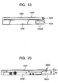
- Opening-and-closing structures such as those shown in Figs. 19 and 20, have conventionally been known as being used in notebook personal computers or the like in order to openably and closably support the display portion with respect to the body.
- a liquid crystal display 1002 is openably and closably mounted to a body 1000 through a hinge 1001.
- a built-in type battery pack 1003 is accommodated in the body 1000.
- a display 2001 is openably and closably mounted to a body 2000 through a hinge mechanism 2002.
- an externally mounting type battery pack 2003 is mounted to the rear end of the body 2000 in order to supply electrical power to the body 2000.
- Fig. 19 has the following problems. Since the shaft of the hinge 1001 is disposed in the back edge 1004 of the thin, panel-shaped liquid crystal display 1002, the diameter of the hinge 1001 must be made smaller than the thickness of the liquid crystal display 1002. This prevents the hinge 1001 from having sufficient mechanical durability and strength. In addition, since the space for passing a signal wire from the body 1000 towards the liquid crystal display 1002 is small, an expensive flexible cable must be used as signal wire.
- this structure is a layered type structure whose overall thickness cannot be reduced.
- Fig. 20 has the following problems. Since the hinge mechanism 2002 and the battery pack 2003 are not coaxially disposed, a portion, with a thickness R1, for coupling the display 2001 and the hinge 2002 together must be provided. This means that the overall thickness of the portable personal computer is equal to the sum of thickness R1 of the coupling portion and the outside thickness R2 of the externally mounting type battery pack 2003. Consequently, the coupling portion with thickness R1 prevents the overall thickness of the portable personal computer from being reduced.
- the presence of the battery pack 2003 limits the opening and closing range of the display 2001 to less than 180 degrees.
- an object of the present invention to provide an electronic device which can eliminate the above-described problems to eliminate the factors that prevent the overall thickness of the electronic device from being reduced due to the presence of an externally mounting type battery, and which allows the display portion to be opened and closed with respect to the body by more than 180 degrees; 'and to provide an electronic device battery.
- an electronic device comprising at least a pair of opening-and-closing mechanical portions for openably and closably supporting a display portion with respect to a body; and a battery, disposed between the pair of opening-and-closing mechanical portions, for supplying electrical driving power to the body.
- a pair of opening-and-closing mechanical portions are provided, with a battery being disposed between these opening-and-closing mechanical portions.
- each of the opening-and-closing mechanical portions can be formed to substantially the same outer diameter as the battery, the opening-and-closing mechanical portions can be made mechanically more durable and strong.
- such a structure allows the display portion to be opened by more than 180 degrees with respect to the body, since the battery in no way interferes with the opening and closing operations of the display portion. Still further, even if, by mistake, the user opens the display portion by more than 180 degrees, breakage of the body, the display portion, or the battery does not occur.
- the pair of opening-and-closing mechanical portions may comprise a first opening-and-closing mechanical portion, disposed between one side end of the body and one side end of the display portion, for openably and closably supporting the display portion with respect to the body; and a second opening-and-closing mechanical portion, disposed between the other side end of the body and the other side end of the display portion, for openably and closably supporting the display portion with respect to the body; wherein the battery is disposed between the first opening-and-closing mechanical portion and the second opening-and-closing mechanical portion.
- Such a structure allows the electronic device to be made thinner even when a battery is externally mounted. Disposing the first opening-and-closing mechanical portion and the second opening-and-closing mechanical portion at both ends of the battery allows the first opening-and-closing mechanical portion and the second opening-and-closing mechanical portion to have about the same outside dimensions as the battery, and thus to have sufficient mechanical durability and strength.
- the opening-and-closing mechanical portion and the second opening-and-closing mechanical portion are disposed between the ends of the body and the display portion, the opening-and-closing mechanical portions can be increased in size, and sufficient space can be obtained for providing a signal wire from a circuit portion of the body to the display portion, allowing the use of a cheap ordinary wire and designing with greater freedom.
- the pair of opening-and-closing mechanical portions may both comprise cylindrical hinge mechanisms; and the battery may be cylindrical in shape which has substantially the same diameter as the hinge mechanisms, with the centers of rotation of the hinge mechanisms being disposed on a line extended from the axial line of the battery.
- the electronic device to be made thinner even when a battery is externally mounted, and to have a good appearance, and the outer dimensions of the battery and the hinges can be made equal to the overall thickness of the electronic device. Accordingly, the entire electronic device can be made thin, and the battery and the hinges can be made large, thereby satisfying two opposing design specification demands.
- either one or both of the opening-and-closing mechanical portions may comprise hinge mechanisms constructed to conduct heat such that the heat that is generated in a body case is made to travel towards a display portion case, through the hinge mechanism or the hinge mechanisms.
- the electronic device may further comprise a guiding mechanical portion for guiding the battery in a direction of insertion and removal of the battery, when the battery is being mounted to and removed from the body.
- the electronic device may further comprise a connecting mechanical portion for removably mounting the battery to the body, and for mechanically and electrically connecting the battery to the body; and a guiding mechanical portion for guiding the battery in a direction of insertion and removal of the battery, when the battery is being mounted to and removed from the body.
- the guiding mechanical portion may comprise a first guiding mechanical portion which is disposed between one end of the battery and the first opening-and-closing mechanical portion, and a second guiding mechanical portion which is disposed between the other end of the battery and the second opening-and-closing mechanical portion.
- the electronic device may further comprise a securing mechanical portion for securing the battery being mounted to the body.
- the securing mechanical portion and the connecting mechanical portion for removably mounting the battery may be disposed in a row at the contact surfaces of the body and the battery.
- an electronic device comprising at least a pair of opening-and-closing mechanical portions for openably and closably supporting a display portion with respect to a body; and a body side connecting mechanical portion, disposed between the pair of opening-and-closing mechanical portions, for removably mounting a battery supplying electrical driving power to the body.
- the external form of the battery allows the external form of the battery to be designed with sufficient freedom.
- the battery can take various forms and have various dimensions on the physical condition that it fits between the pair of opening-and-closing mechanical portions. Therefore, the external form of the battery is not limited by the form of the body, thereby allowing the external form of the battery itself to be designed freely.
- an electronic device battery mounted to a body side connecting mechanical portion that is disposed between at least a pair of opening-and-closing mechanical portions that openably and closably support a display portion with respect to a body, the electronic device battery comprising a battery side connecting mechanical portion which is removably fitted to the body side connecting mechanical portion.
- the external form of the electronic device battery is not limited by the external form of the body, thereby allowing the battery to be freely designed into, for example, a cylindrical shape. This eliminates the need for protrusions, making the electronic device battery easier to carry, and allowing it to be formed into an excellent form from the viewpoint of designing.
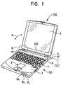
- Fig. 1 illustrates an electronic device in accordance with an embodiment of the present invention.
- the electronic device of Fig. 1 is a portable computer 100.
- the portable computer 100 includes a body 2, a display portion 3, a keyboard 4, hinges 1A and 1B within areas A and B, and a battery pack 200, etc.
- the body 2 has the aforementioned keyboard 4 and a pointing device 5 or the like, and the display portion 3 may be, for example, a liquid crystal display (LCD) portion.
- the hinges 1A and 1B (first opening-and-closing portion and second opening-and-closing portion) are mounted to the body 2 so as to allow opening and closing operations in the directions of a double-headed arrow R.
- a device such as a mouse being an externally mounting type pointing means, may be set with respect to the body 2 from outside the electronic device.
- the body has a power supply lamp PL, a battery lamp BL, and a message lamp ML, with the battery lamp BL indicating the amount of power left in the battery pack 200.
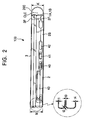
- Fig. 2 illustrates the display portion 3 of the electronic device of Fig. 1 being folded onto the body 2, with a center axis CLC as center, as viewed in a direction of arrow SD.
- a power supply switch 40 at a side face 2S of the body 2 are disposed a power supply switch 40, and other switches 41 and 42.
- a slot 43 for inserting therein an electronic card (PC card).
- PC card electronic card
- the thickness of one end portion of the body 2 and the thickness of one end portion of the display portion 3 are represented by t1 to t4, which are set at very small values.
- thickness t1 is set at 1.2 mm
- thickness t2 at 1.0 mm
- thickness t3 at 1.0 mm
- thickness t4 at 1.2 mm.
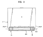
- a feature in Figs. 1 to 3 is that the battery pack 200 is disposed between the hinges 1A and 1B.
- Center axis CLC which corresponds to the rotational center of the hinges 1A and 1B, lies on the extension line of the axis of the battery pack 200.
- the center axis of the battery pack 200 and the center axis of the hinges 1A and 1B are disposed coaxially.
- the battery pack 200 is removably mounted to the body 2 and is electrically connected when it is mounted.
- the battery pack 200 is located in the vicinity of rear end 2F of the body 2 and rear end 3F of the display portion 3.
- the battery pack 200 and the hinges 1A and 1B have substantially the same diameters, and diameter K thereof is about the same as thickness M equal to the sum of the display portion 3 and the body 2 when the display portion 3 is folded upon the body 2. This causes the capacity of the battery pack 200 to become large while making the thickness M of the portable computer 100 as small as possible, and the diameter K of the hinges 1A and 1B can be made as large as possible. As a result, the hinges 1A and 1B have sufficient durability and strength.
- the battery pack 200 is disposed at the back end 2F of the body 2 and between the hinges 1A and 1B.
- the battery pack 200 has the shape shown in Figs. 7 to 13.
- secondary batteries such as lithium ion secondary batteries, may be used for the battery pack with a case 201.
- the case 201 is formed, for example, by plastic molding, and has one or more battery cells contained therein.
- the case 201 has mechanical mounting portions 202, grooves 203, and an electrical connecting terminal 204.
- the case 201 has two ground portions 205 that support the battery pack 200 so that the battery pack 200 does not slide along the supporting surface of, for example, a desk.
- These ground portions 205 are made of, for example, rubber.
- the grooves 203 are formed in the left end and the right end of the case 201 in a horizontal direction N in Fig. 7.
- the mounting portions 202 protrude from a contact surface of the case 201. Between the mounting portions 202 and 202 and at the contact surface 209 is disposed the male electrical connecting terminal 204.
- Recesses 302 are formed in the back end 2F of the body 2 in correspondence with the mounting portions 202.
- the body 2 has an electrical connecting terminal 304 for electrically inserting therein the electrical connecting terminal 204.
- Guide projections 303 are provided at the body side of the hinges 1A and 1B. By inserting the projections 303 into the grooves 203 at both ends of the battery pack 200, the battery pack 200 can be guided along the direction of the double-headed arrow N1 and fitted to the hinges 1A and 1B.
- the grooves 203 and the protrusions 303 form an engaging portion or a guide mechanical portion.
- the mounting portions 202 of the battery pack 200 are fitted into their corresponding recesses 302 in the body 2. Accordingly, the battery pack 200 is reliably electrically and mechanically mounted to the body 2 so as to be removable therefrom. Accordingly, with the battery pack 200 mounted to the body 2, electrical driving power is supplied from the battery pack 200 to the body 2 through the electrically connecting terminal 204.
- the mounting portions 202 are mechanically fitted into their respective recesses 302 in the body 2, and the electrically connecting terminal 204 is electrically connected to an electrically connecting terminal 304 of the body 2.
- the grooves 203 and the protrusions 303 allow the battery pack 200 to be guided. Therefore, it is possible to prevent breakage of the electrically connecting terminals 204 and 304 caused by stress produced when the electrically connecting terminal 204 of the battery pack 200 is being mounted to or removed from the electrically connecting terminal 304.
- the grooves 203 are formed in both ends of the battery pack 200, while the protrusions 303, which are guided and slid along their respective grooves 203, are formed in the surfaces of the hinges (opening-and-closing mechanical portions) 1A and 1B which oppose both ends of the battery pack 200.
- the grooves 203 may be formed in the surfaces of the hinges (opening-and-closing mechanical portions) 1A and 1B which oppose both ends of the battery pack, and the protrusions 303, which are guided and slide along their respective grooves 203, may be formed on both ends of the battery pack 200.
- the battery pack 200 is disposed between the hinges 1A and 1B (the pair of opening-and-closing mechanical portions), thereby allowing the display portion to open with respect to the body 2 through an angle of more than 180 degrees.
- the display portion 3 can be opened with respect to the body 2 through an angle of more than 180 degrees. For example, even if a user sits on a chair, with his or her legs crossed, and performs key input operations after placing the body 2 on his or her knees, the user can open the display portion 3 by more than 180 degrees.
- the display surface of the display portion 3 can always be maintained at right angles from the direction of line of sight, allowing the user, who is seated in a desired posture and has a good field of view, to concentrate on key input operations.
- the user inadvertently opens the display portion 3 by more than 180 degrees, breakage of the portion connecting the body 2 and the display portion 3 or breakage of the battery pack 200 does not occur.
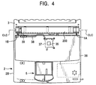
- Figs. 4, 5, and 14 illustrate a central processing unit (CPU) 35, serving as heat-generating source in the electronic device of the present invention, a case 2B of the body 2, the hinge 1B, and the case 3A of the display portion 3.
- Fig. 4 illustrates an example of a process in which heat generated as a result of driving the central processing unit 35 serving as a heat-generating source, is either radiated or dissipated from a base 36, having mounted thereto the central processing unit 35, towards the case 3A of the display portion 3, through the hinge 1B or the like.
- the base 36 is disposed in the case 2B of Fig. 14, with the central processing unit 35 mounted on the base 36.
- the case 3A and the case 2B are mechanically joined together by the hinges 1A and 1B (the hinge 1A is not shown) so as to allow opening and closing operations, and are designed to allow conduction of heat of the central processing unit 35 from the base 36 towards the case 3A.
- the central processing unit 35 is disposed at virtually the center of the base 36, so that the central processing unit 35 is separated from the hinge 1B.
- a heat-receiving plate 37 for receiving the heat from the central processing unit 35, a heat pipe 38, and a connector 39 are disposed between the hinge 1B and the central processing unit 35.
- the heat-receiving plate 37 is disposed above the central processing unit 35, at a predetermined distance therefrom.
- the heat-receiving plate 37 and the connector 39 are connected by the heat pipe 38.
- the heat pipe 38 and the heat-receiving plate 37 are made of metal which conducts heat well, such as copper.
- the heat-receiving plate 37 is larger than the central processing unit 35.
- the connector 39 is also made of a metal which conducts heat well, such as copper, and can be secured to the case 2B side of the body 2 by screwing screws 31 into a fixed portion 11 of the hinge 1B.
- a movable portion 17 of the hinge 1B is secured to the inside of the case 3A using screws 32.
- the hinge 1B is capable of efficiently conducting heat from the fixed portion 11 side towards the movable portion 17.
- the heat is transferred towards the movable portion 17, in the direction of arrow AL6. From the movable portion 17, the heat, which is transferred in the direction of arrow AL7, is radiated or dissipated at the case 3A.
- case 2B of the body 2 is also called a bottom cabinet
- the base 36 is also called a main base
- the case 3A of the display portion 3 is also called an outside cabinet.
- the hinges 1A and 1B of Fig. 1 mechanically join the display portion 3 to the back end 6 of the body 2, and are designed to conduct or dissipate heat.
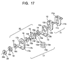
- the hinges 1A and 1B which are symmetrically formed on the left and right sides, have essentially the same structure. Therefore, only the structure and features of the hinge 1A are described, with reference to Figs. 15 to 17.
- the hinge 1A has fixed portion 11, movable portion 17, and a coupling portion 30.
- the coupling portion of Fig. 17 is used for coupling the fixed portion 11 and the movable portion 17 in a mechanical fashion so as to make possible heat conduction.
- the fixed portion 11 is composed of a strength retaining portion 11a for retaining mechanical strength, and a heat-conducting portion 12 for conducting heat. It is preferable that the strength retaining portion 11a be made of a material having high mechanical strength, such as stainless steel (SUS) being an iron type material, in order to retain the strength of the strength-retaining portion 11a and to keep the display portion 3 of Fig. 1 in an openable and closable state when the display portion 3 of Fig. 1 is being opened and closed.
- the strength retaining portion 11a which is composed of a plate-shaped material with high mechanical strength, is formed into a substantially L shape in cross section.
- the heat-conducting portion 12 is preferably made of a material which is suitable for heat conduction, such as a copper type or an aluminum type material. It is formed into the shape of a plate, and is substantially L-shaped in cross section in order to bring it into close contact with and to secure it to or set it at the strength retaining portion 11a.
- the strength retaining portion 11a of the fixed portion 11 and the heat-conducting portion 12 are brought into close contact for use, with the fixed portion 11 being secured to the body 2 mounting surface side (or the side contacting the body) using, for example, screws 31.
- Fig. 17 is a perspective view showing a form of the strength retaining portion 11a of the fixed portion 11 and the heat-conducting portion 12. Rectangular holes 11c and 12c are formed in an upstanding portion 11b of the strength retaining portion 11a and the upstanding portion 12b of the heat-conducting portion 12, respectively.
- the movable portion 17 has a strength retaining portion 17a and a heat-conducting portion 13.
- the strength-retaining portion 17a is provided for retaining mechanical strength, whereas the heat-conducting portion 13 is provided for conducting heat.
- the strength retaining portion 17a is preferably made of a material with high mechanical strength, such as stainless steel (SUS) being an iron type material, in order to retain the strength thereof and the strength thereof when the display portion is being opened and closed.
- SUS stainless steel
- the heat-conducting portion 13 is made of a material with good heat conductivity, such as copper or aluminum type material.
- the strength-retaining portion 17a, as well as the heat-conducting portion 13, is substantially L-shaped in cross section. A portion 13a of the heat-conducting portion 13 is brought into close contact with the strength-retaining portion 17a, whereas an upstanding portion 13b of the heat-conducting portion 13 is used so as to be separable from an upstanding portion 17b of the strength-retaining portion 17a.
- Fig. 17 shows, three dimensionally, the strength-retaining portion 17a of the movable portion 17 and the heat-conducting portion 13.
- Circular holes 17c and 13c are formed in the upstanding portion 17b of the strength-retaining portion 17a and the upstanding portion 13b of the heat-conducting portion 13, respectively. It is to be noted that the diameter of the hole 17c is smaller than the diameter of the hole 13c.
- the engaging portion 30 is capable of mechanically joining the fixed portion 11 and the movable portion 17, while allowing heat conduction between the heat-conducting portion 12 of the fixed portion 11 and the heat-conducting portion 13 of the movable portion 17.
- Fig. 17 shows the structural members of the engaging portion 30, which are a spring washer 14, a shaft 15, washers 16 and 18, a spring washer 19, and a stopper 20.
- the shaft 15 is made of, for example, iron in order to, for example, retain mechanical strength, and has a projection 15a and a projection 15b, formed opposite to the projection 15a, both of which are provided with respect to a body 15c of the shaft 15.
- the projection 15a passes through a hole 14a in the spring washer 14, a hole 13c in the heat-conducting portion 13, the hole 12c in the heat-conducting portion 12, and the hole 11c in the strength-retaining portion 11a.
- the projection 15a has end surfaces 15e shaped to allow the projection 15a to be firmly fitted into the hole 12c in the heat-conducting portion 12 and the hole 11c in the strength-retaining portion 11a so that the heat-conducting portion 12 does not move. Accordingly, the projection 15a of the shaft 15 can be firmly fitted into the hole 12c in the heat-conducting portion 12a and the hole 11c in the strength-retaining portion 11a so that it does not move out of the holes 12c and 11c.
- the spring washer 14 is used for holding down the heat-conducting portion 12 of the fixed portion 11 and the heat-conducting portion 13 of the movable portion 17 so that they are in close contact, and is made of a metal, such as iron.
- the washer 16 is disposed between the shaft 15 and the strength-retaining portion 17a of the movable portion 17.
- the washer 16 has a hole 16c, which is rectangular in shape to allow insertion of the projection 15b of the shaft 15 therein.
- the projection 15b of the shaft 15 has planar end surfaces 15f and 15f.
- the projection 15b passes through the hole 17c in the strength-retaining portion 17a, a hole 18c in the washer 18, and a hole 19c in the spring washer 19, so that it can be firmly fitted into a hole 20c in the stopper 20.
- the projection 15b of the shaft 15 is firmly secured at the hole 20c in the stopper 20 so that it does get dislodged.
- the fixed portion 11 and the movable portion 17 can be integrally coupled together by engaging the projection 15a of the shaft 15 and the hole 11c in the strength-retaining portion 11a and engaging the projection 15b of the shaft 15 and the hole 20c in the stopper 20.
- the shaft 15 allows rotation of the movable portion 17 with respect to the fixed portion 11 in the R directions in Fig. 16.
- the shaft 15, the washers 16 and 18, the spring washers 14 and 19, and the stopper 20 are made of, for example, an iron-type material with high mechanical strength.
- the heat-conducting portion 12 of the fixed portion 11 is positioned at the body 2 mounting surface side of the computer 100 of Fig. 1 (or the side contacting the body), and can be secured thereto with the screws 32, as shown in Figs. 15 and 16.
- the heat-conducting portion 13a of the movable portion 17 is positioned at the display portion 3 mounting surface side of the computer 100 of Fig. 1 (or surface for mounting to display portion), and can be secured thereto with the screws 32.
- Such hinges 1A and 1B are capable of retaining mechanical strength and conducting and dissipating heat, so that heat conduction between, for example, the body 2 of the computer 100 and the display portion 3 can be improved by allowing easy transfer of heat from a location where there is a larger amount of heat, such as the body 2, to a location where there is a smaller amount of heat, such as the display portion 3.
- heat can be easily transferred from the body 2 where a larger amount of heat is generated to the display portion 3 where a smaller amount of heat is generated, thereby providing a location for heat dissipation, and allowing new heat-dissipating means such as a heat sink to be provided at the heat-conducting portion 12 and the heat-conducting portion 13, so that heat can be dissipated with greater efficiency.
- cases 2A and 3A of the body 2 and the display portion 3 of Fig. 14, respectively, are made of a light metal, such as magnesium
- these cases 2A and 3A themselves, can be used as heat sinks, which, when thermally connected to the heat-conducting portion 12 and the heat-conducting portion 13 of Fig. 14, can further increase the heat-dissipating effect.
- the transferred heat can be dissipated externally of the entire case 3A.
- magnesium alloy for the case 3A.
- Magnesium materials such as AZ91D, may be used for the magnesium alloy.
- the heat conductivity of the magnesium thereof is 157 W/mK.
- the thickness of the case 3A is, for example. 1.2 mm.
- the dimensions of the case 3A are, for example, 259 mm x 208.6 mm x 23.9 mm.
- Usable central process units include, for example, a Pentium processor 133 MHz, a trade name of an Intel product. The Pentium processor 133 MHz generates about 6 W of heat per unit time.
- heat transfer between different parts of the electronic device is improved by allowing heat to be transferred easily from a location where there is a larger amount of heat to a location where there is a smaller amount of heat.
- heat can be easily transferred from the body where a larger amount of heat is generated to the display portion where a smaller amount of heat is generated; thereby providing a place for heat dissipation, and allowing heat-dissipating means, such as heat sinks, to be provided, so that heat is dissipated with greater efficiency.
- the hinges 1A and 1B are provided at the back ends 2F and 3F of the body 2 and the display portion 3, and the battery pack 200 is disposed between the hinges 1A and 1B, so that the battery pack 200 is positioned outwardly of the body 2 and the display portion 3. Since the thickness obtained when the display portion 3 is folded upon the body 1 can be formed to about the diameter of the battery pack, the entire portable computer can be made thin.
- the battery pack 200 and the hinges 1A and 1B can be formed with the maximum diameter possible within the range the entire computer has been made thin, thereby making the hinges more durable and increasing the capacity of the battery pack 200.
- the hinges 1A and 1B which are effective in conducting heat and have mechanical strength, are disposed between the body 2 and the display portion 3 serving as cover, and heat can be conducted between the cases of the hinges 1A and 1B, so that even when the portable computer is made thin, heat can be dissipated. Therefore, a thinner portable computer does not result in heat-related problems.
- the battery pack 200 can be removably mounted to the body 2, the battery pack 200 is easy to replace.
- the battery pack 200 can ordinarily be charged from the body side at all times. Since the diameter of the hinges 1A and 1B can at least be the same as the diameter of the battery pack, a sufficient signal wire disposing space can be ensured for sending a signal from a circuit in the body 2 to the liquid crystal display portion 3, thereby allowing the use of a cheap, ordinary electrical wire for the signal wire.
- the battery pack is substantially circular in cross section, the battery pack may take other forms.
- the present invention is not limited to the above-described embodiment.
- the electronic device of the present invention may be used for various electronic devices which generate a large amount of heat, such as portable information terminals, portable telephones, or radio devices.
- a pair of opening-and-closing portions are provided in order to openably and closably support the display portion with respect to the body, with a battery being disposed between the opening-and-closing portions.
- the electronic device can be made thin, and the opening-and-closing mechanical portions can be formed to approximately the outside dimensions of the battery, making it possible to increase the mechanical durability and strength of the opening-and-closing mechanical portions.
- the battery in no way interferes with the opening-and-closing operation of the display portion, so that the display portion can be opened by more than 180 degrees with respect to the body.
- the display portion can be opened by more than 180 degrees with respect to the body.
- damage to the body or the display portion does not occur.
- the present invention directed to the body of the electronic device excluding the battery, there is provided at least a pair of opening-and-closing mechanical portions for openably and closably supporting a display portion with respect to a body, and a body side connecting mechanical portion, disposed between the pair of opening-and-closing mechanical portions, for removably mounting a battery which supplies electrical driving power to the body.
- the external form of the battery is not limited by the form of the body, thereby allowing the external form of the battery itself to be designed with sufficient freedom.
- the battery which is mounted to a body side connecting mechanical portion that is disposed between at least a pair of opening-and-closing mechanical portions that openably and closably support a display portion with respect to a body, comprises a battery side connecting mechanical portion which is removably fitted to the body side connecting mechanical portion.
- the external shape of the electronic device battery can be designed with sufficient freedom, independently of the form of the body.
- the electronic device battery can be formed into a cylindrical shape. This eliminates the need for protrusions, making the electronic device battery easier to carry, and allowing it to be formed into an excellent form from the viewpoint of designing.
Abstract
Description
- The present invention relates to an electronic device, such as one having a display portion capable of being opened and closed with respect to its body by more than 180 degrees. The present invention also relates to a battery for this type of electronic device.
- In recent years, many portable electronic devices incorporating a central processing unit (CPU), such as notebook personal computers and mobile computers, have been made commercially available. In such electronic devices, the CPU is driven at a high clock frequency, so that a large amount of electrical power is consumed at the CPU, as a result of which electrical power consumption is concentrated at the CPU. Consequently, such electronic devices require a means for efficiently dissipating the heat of the CPU outside the CPU.
- In general, portable electronic devices, such as notebook personal computers, comprise a body and a display portion. The display portion can be opened and closed with respect to the body through hinges.
- Opening-and-closing structures, such as those shown in Figs. 19 and 20, have conventionally been known as being used in notebook personal computers or the like in order to openably and closably support the display portion with respect to the body.
- In the conventionally known opening-and-closing structure of Fig. 19, a
liquid crystal display 1002 is openably and closably mounted to abody 1000 through ahinge 1001. In addition, a built-intype battery pack 1003 is accommodated in thebody 1000. - On the other hand, in the conventionally known opening-and-closing structure of Fig. 20, a
display 2001 is openably and closably mounted to abody 2000 through ahinge mechanism 2002. In addition, an externally mountingtype battery pack 2003 is mounted to the rear end of thebody 2000 in order to supply electrical power to thebody 2000. - However, the structure of Fig. 19 has the following problems. Since the shaft of the
hinge 1001 is disposed in theback edge 1004 of the thin, panel-shapedliquid crystal display 1002, the diameter of thehinge 1001 must be made smaller than the thickness of theliquid crystal display 1002. This prevents thehinge 1001 from having sufficient mechanical durability and strength. In addition, since the space for passing a signal wire from thebody 1000 towards theliquid crystal display 1002 is small, an expensive flexible cable must be used as signal wire. - Further, in this structure, the
rear end 1004 of theliquid crystal display 1002 is folded on top of the battery pack consisting of a plurality ofbatteries 1003A arranged in a row. Therefore, this structure is a layered type structure whose overall thickness cannot be reduced. - The structure of Fig. 20 has the following problems. Since the
hinge mechanism 2002 and thebattery pack 2003 are not coaxially disposed, a portion, with a thickness R1, for coupling thedisplay 2001 and thehinge 2002 together must be provided. This means that the overall thickness of the portable personal computer is equal to the sum of thickness R1 of the coupling portion and the outside thickness R2 of the externally mountingtype battery pack 2003. Consequently, the coupling portion with thickness R1 prevents the overall thickness of the portable personal computer from being reduced. - In the structure of Fig. 20, the presence of the
battery pack 2003 limits the opening and closing range of thedisplay 2001 to less than 180 degrees. - Accordingly, it is an object of the present invention to provide an electronic device which can eliminate the above-described problems to eliminate the factors that prevent the overall thickness of the electronic device from being reduced due to the presence of an externally mounting type battery, and which allows the display portion to be opened and closed with respect to the body by more than 180 degrees; 'and to provide an electronic device battery.
- To this end, according to one aspect of the present invention, there is provided an electronic device comprising at least a pair of opening-and-closing mechanical portions for openably and closably supporting a display portion with respect to a body; and a battery, disposed between the pair of opening-and-closing mechanical portions, for supplying electrical driving power to the body.
- According to the present invention, in order to openably and closably support the display portion to the body, a pair of opening-and-closing mechanical portions are provided, with a battery being disposed between these opening-and-closing mechanical portions.
- Such a structure allows the electronic device to be made thinner even when a battery is externally mounted to the body of the electronic device. In addition, since each of the opening-and-closing mechanical portions can be formed to substantially the same outer diameter as the battery, the opening-and-closing mechanical portions can be made mechanically more durable and strong.
- Further, such a structure allows the display portion to be opened by more than 180 degrees with respect to the body, since the battery in no way interferes with the opening and closing operations of the display portion. Still further, even if, by mistake, the user opens the display portion by more than 180 degrees, breakage of the body, the display portion, or the battery does not occur.
- Although not exclusive, the pair of opening-and-closing mechanical portions may comprise a first opening-and-closing mechanical portion, disposed between one side end of the body and one side end of the display portion, for openably and closably supporting the display portion with respect to the body; and a second opening-and-closing mechanical portion, disposed between the other side end of the body and the other side end of the display portion, for openably and closably supporting the display portion with respect to the body; wherein the battery is disposed between the first opening-and-closing mechanical portion and the second opening-and-closing mechanical portion.
- Such a structure allows the electronic device to be made thinner even when a battery is externally mounted. Disposing the first opening-and-closing mechanical portion and the second opening-and-closing mechanical portion at both ends of the battery allows the first opening-and-closing mechanical portion and the second opening-and-closing mechanical portion to have about the same outside dimensions as the battery, and thus to have sufficient mechanical durability and strength.
- In addition, since the first opening-and-closing mechanical portion and the second opening-and-closing mechanical portion are disposed between the ends of the body and the display portion, the opening-and-closing mechanical portions can be increased in size, and sufficient space can be obtained for providing a signal wire from a circuit portion of the body to the display portion, allowing the use of a cheap ordinary wire and designing with greater freedom.
- Although not exclusive, the pair of opening-and-closing mechanical portions may both comprise cylindrical hinge mechanisms; and the battery may be cylindrical in shape which has substantially the same diameter as the hinge mechanisms, with the centers of rotation of the hinge mechanisms being disposed on a line extended from the axial line of the battery.
- This allows the electronic device to be made thinner even when a battery is externally mounted, and to have a good appearance, and the outer dimensions of the battery and the hinges can be made equal to the overall thickness of the electronic device. Accordingly, the entire electronic device can be made thin, and the battery and the hinges can be made large, thereby satisfying two opposing design specification demands.
- Although not exclusive, either one or both of the opening-and-closing mechanical portions may comprise hinge mechanisms constructed to conduct heat such that the heat that is generated in a body case is made to travel towards a display portion case, through the hinge mechanism or the hinge mechanisms.
- This allows heat, generated at the body, to be dissipated by a larger amount, even when the electronic device is made thinner.
- Although not exclusive, the electronic device may further comprise a guiding mechanical portion for guiding the battery in a direction of insertion and removal of the battery, when the battery is being mounted to and removed from the body.
- This facilitates sliding of the battery when it is being mounted to or removed from the body.
- Although not exclusive, the electronic device may further comprise a connecting mechanical portion for removably mounting the battery to the body, and for mechanically and electrically connecting the battery to the body; and a guiding mechanical portion for guiding the battery in a direction of insertion and removal of the battery, when the battery is being mounted to and removed from the body.
- This prevents damage to the electrically connecting terminal, etc., of the connecting mechanical portion caused by undue stress exerted thereupon during mounting and removal to and from the body.
- Although not exclusive, the guiding mechanical portion may comprise a first guiding mechanical portion which is disposed between one end of the battery and the first opening-and-closing mechanical portion, and a second guiding mechanical portion which is disposed between the other end of the battery and the second opening-and-closing mechanical portion.
- This prevents damage to the electrically connecting terminal, etc., caused by stress exerted thereupon during mounting of the battery, using a simple structure.
- Although not exclusive, the electronic device may further comprise a securing mechanical portion for securing the battery being mounted to the body.
- This allows the battery to be reliably positioned at and secured to the body.
- Although not exclusive, the securing mechanical portion and the connecting mechanical portion for removably mounting the battery may be disposed in a row at the contact surfaces of the body and the battery.
- This allows the battery to be secured to the body by the securing mechanical portion, and, at the same time, the battery to be electrically connected to the body by the connecting mechanical portion, by simply bringing the contact surfaces of the body and the battery into contact with each other.
- According to another aspect of the present invention, there is provided an electronic device comprising at least a pair of opening-and-closing mechanical portions for openably and closably supporting a display portion with respect to a body; and a body side connecting mechanical portion, disposed between the pair of opening-and-closing mechanical portions, for removably mounting a battery supplying electrical driving power to the body.
- Such a structure allows the external form of the battery to be designed with sufficient freedom. In other words, the battery can take various forms and have various dimensions on the physical condition that it fits between the pair of opening-and-closing mechanical portions. Therefore, the external form of the battery is not limited by the form of the body, thereby allowing the external form of the battery itself to be designed freely.
- According to still another aspect of the present invention, there is provided an electronic device battery mounted to a body side connecting mechanical portion that is disposed between at least a pair of opening-and-closing mechanical portions that openably and closably support a display portion with respect to a body, the electronic device battery comprising a battery side connecting mechanical portion which is removably fitted to the body side connecting mechanical portion.
- The external form of the electronic device battery is not limited by the external form of the body, thereby allowing the battery to be freely designed into, for example, a cylindrical shape. This eliminates the need for protrusions, making the electronic device battery easier to carry, and allowing it to be formed into an excellent form from the viewpoint of designing.
- The invention will now be described by way of example with reference to the accompanying drawings, throughout which like parts are referred to by like references, and in which:
- Fig. 1 is a perspective view of an electronic device in accordance with an embodiment of the present invention;
- Fig. 2 is a side view of a computer serving as the electronic device of Fig. 1;
- Fig. 3 is a plan view of a display portion being in a closed state with respect to the body of the electronic device;
- Fig. 4 is a plan view of the body and a battery pack;
- Fig. 5 illustrates the body and the battery pack, with the display portion being in a removed state;
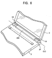
- Fig. 6 is a perspective view of part of the structure consisting of the body, the display portion, and the battery pack;
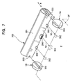
- Fig. 7 is a perspective view showing the relationship between the connecting parts of the battery pack and those of the body;
- Fig. 8 is a front view of the battery pack;
- Fig. 9 is a plan view of the battery pack;
- Fig. 10 is a sectional view taken along line X-X of Fig. 9;
- Fig. 11 is a sectional view taken along line XI-XI of Fig. 9;
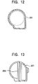
- Fig. 12 is a sectional view taken along line XII-XII of Fig. 9;
- Fig. 13 is a side view of the battery pack as viewed from direction XIII of Fig. 9;
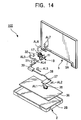
- Fig. 14 is an exploded perspective view of the body case, the display portion case, and hinges for heat conduction and for mechanical joining, shown in Fig. 1;
- Fig. 15 is a plan view of an example of a hinge;
- Fig. 16 is a side view of the hinge;
- Fig. 17 is an exploded perspective view of the hinge structure;
- Fig. 18 is a perspective view of an electronic device embodying the present invention in one condition of use;
- Fig. 19 illustrates the structure of a conventional portable computer; and
- Fig. 20 illustrates the structure of another conventional portable computer.
-
- Since the embodiment to be described below is a preferred embodiment of the present invention, various specific technological forms are described below. However, unless otherwise specified, these technological forms in no way limit the scope of the present invention.
- Fig. 1 illustrates an electronic device in accordance with an embodiment of the present invention. The electronic device of Fig. 1 is a
portable computer 100. Theportable computer 100 includes abody 2, adisplay portion 3, akeyboard 4, hinges 1A and 1B within areas A and B, and abattery pack 200, etc. - The
body 2 has theaforementioned keyboard 4 and apointing device 5 or the like, and thedisplay portion 3 may be, for example, a liquid crystal display (LCD) portion. Thehinges body 2 so as to allow opening and closing operations in the directions of a double-headed arrow R. Although not illustrated in Fig. 1, a device, such as a mouse being an externally mounting type pointing means, may be set with respect to thebody 2 from outside the electronic device. The body has a power supply lamp PL, a battery lamp BL, and a message lamp ML, with the battery lamp BL indicating the amount of power left in thebattery pack 200. - Fig. 2 illustrates the
display portion 3 of the electronic device of Fig. 1 being folded onto thebody 2, with a center axis CLC as center, as viewed in a direction of arrow SD. In Fig. 2, at aside face 2S of thebody 2 are disposed apower supply switch 40, andother switches side face 2S is disposed aslot 43 for inserting therein an electronic card (PC card). - In Fig. 2, the thickness of one end portion of the
body 2 and the thickness of one end portion of thedisplay portion 3 are represented by t1 to t4, which are set at very small values. For example, thickness t1 is set at 1.2 mm, thickness t2 at 1.0 mm, thickness t3 at 1.0 mm, and thickness t4 at 1.2 mm. - A feature in Figs. 1 to 3 is that the
battery pack 200 is disposed between thehinges hinges battery pack 200. In other words, the center axis of thebattery pack 200 and the center axis of thehinges battery pack 200 is removably mounted to thebody 2 and is electrically connected when it is mounted. - As shown in Figs. 2 and 3, the
battery pack 200 is located in the vicinity ofrear end 2F of thebody 2 andrear end 3F of thedisplay portion 3. Thebattery pack 200 and thehinges display portion 3 and thebody 2 when thedisplay portion 3 is folded upon thebody 2. This causes the capacity of thebattery pack 200 to become large while making the thickness M of theportable computer 100 as small as possible, and the diameter K of thehinges hinges - As shown in Figs. 4, 5, and 6, the
battery pack 200 is disposed at theback end 2F of thebody 2 and between thehinges battery pack 200 has the shape shown in Figs. 7 to 13. For example, secondary batteries, such as lithium ion secondary batteries, may be used for the battery pack with acase 201. Thecase 201 is formed, for example, by plastic molding, and has one or more battery cells contained therein. Thecase 201 has mechanical mountingportions 202,grooves 203, and an electrical connectingterminal 204. - As shown in Figs. 8 and 10, the
case 201 has twoground portions 205 that support thebattery pack 200 so that thebattery pack 200 does not slide along the supporting surface of, for example, a desk. Theseground portions 205 are made of, for example, rubber. - The
grooves 203 are formed in the left end and the right end of thecase 201 in a horizontal direction N in Fig. 7. The mountingportions 202 protrude from a contact surface of thecase 201. Between the mountingportions contact surface 209 is disposed the male electrical connectingterminal 204. -
Recesses 302 are formed in theback end 2F of thebody 2 in correspondence with the mountingportions 202. Thebody 2 has an electrical connectingterminal 304 for electrically inserting therein the electrical connectingterminal 204. -
Guide projections 303 are provided at the body side of thehinges projections 303 into thegrooves 203 at both ends of thebattery pack 200, thebattery pack 200 can be guided along the direction of the double-headed arrow N1 and fitted to thehinges grooves 203 and theprotrusions 303 form an engaging portion or a guide mechanical portion. The mountingportions 202 of thebattery pack 200 are fitted into their correspondingrecesses 302 in thebody 2. Accordingly, thebattery pack 200 is reliably electrically and mechanically mounted to thebody 2 so as to be removable therefrom. Accordingly, with thebattery pack 200 mounted to thebody 2, electrical driving power is supplied from thebattery pack 200 to thebody 2 through the electrically connectingterminal 204. - In other words, the mounting
portions 202 are mechanically fitted into theirrespective recesses 302 in thebody 2, and the electrically connectingterminal 204 is electrically connected to an electrically connectingterminal 304 of thebody 2. - In addition, the
grooves 203 and theprotrusions 303 allow thebattery pack 200 to be guided. Therefore, it is possible to prevent breakage of the electrically connectingterminals terminal 204 of thebattery pack 200 is being mounted to or removed from the electrically connectingterminal 304. - In the aforementioned guiding mechanical portion, the
grooves 203 are formed in both ends of thebattery pack 200, while theprotrusions 303, which are guided and slid along theirrespective grooves 203, are formed in the surfaces of the hinges (opening-and-closing mechanical portions) 1A and 1B which oppose both ends of thebattery pack 200. Obviously, however, thegrooves 203 may be formed in the surfaces of the hinges (opening-and-closing mechanical portions) 1A and 1B which oppose both ends of the battery pack, and theprotrusions 303, which are guided and slide along theirrespective grooves 203, may be formed on both ends of thebattery pack 200. - In such a configuration described above, the
battery pack 200 is disposed between thehinges body 2 through an angle of more than 180 degrees. In other words, since thebattery pack 200 does not at all interfere with the opening and closing of thedisplay portion 3, thedisplay portion 3 can be opened with respect to thebody 2 through an angle of more than 180 degrees. For example, even if a user sits on a chair, with his or her legs crossed, and performs key input operations after placing thebody 2 on his or her knees, the user can open thedisplay portion 3 by more than 180 degrees. Therefore, the display surface of thedisplay portion 3 can always be maintained at right angles from the direction of line of sight, allowing the user, who is seated in a desired posture and has a good field of view, to concentrate on key input operations. In addition, even if the user inadvertently opens thedisplay portion 3 by more than 180 degrees, breakage of the portion connecting thebody 2 and thedisplay portion 3 or breakage of thebattery pack 200 does not occur. - Figs. 4, 5, and 14 illustrate a central processing unit (CPU) 35, serving as heat-generating source in the electronic device of the present invention, a
case 2B of thebody 2, thehinge 1B, and thecase 3A of thedisplay portion 3. Fig. 4 illustrates an example of a process in which heat generated as a result of driving thecentral processing unit 35 serving as a heat-generating source, is either radiated or dissipated from abase 36, having mounted thereto thecentral processing unit 35, towards thecase 3A of thedisplay portion 3, through thehinge 1B or the like. - More specifically, the
base 36 is disposed in thecase 2B of Fig. 14, with thecentral processing unit 35 mounted on thebase 36. Thecase 3A and thecase 2B are mechanically joined together by thehinges hinge 1A is not shown) so as to allow opening and closing operations, and are designed to allow conduction of heat of thecentral processing unit 35 from the base 36 towards thecase 3A. - In Figs. 4 and 5, the
central processing unit 35 is disposed at virtually the center of thebase 36, so that thecentral processing unit 35 is separated from thehinge 1B. At thecentral processing unit 35 side, a heat-receivingplate 37 for receiving the heat from thecentral processing unit 35, aheat pipe 38, and aconnector 39 are disposed between thehinge 1B and thecentral processing unit 35. The heat-receivingplate 37 is disposed above thecentral processing unit 35, at a predetermined distance therefrom. The heat-receivingplate 37 and theconnector 39 are connected by theheat pipe 38. Theheat pipe 38 and the heat-receivingplate 37 are made of metal which conducts heat well, such as copper. The heat-receivingplate 37 is larger than thecentral processing unit 35. - The
connector 39 is also made of a metal which conducts heat well, such as copper, and can be secured to thecase 2B side of thebody 2 by screwingscrews 31 into a fixedportion 11 of thehinge 1B. - A
movable portion 17 of thehinge 1B is secured to the inside of thecase 3A using screws 32. - As will be described below, the
hinge 1B is capable of efficiently conducting heat from the fixedportion 11 side towards themovable portion 17. - A description will now be given of how heat, generated at the
central processing unit 35, is transferred towards thecase 3A, with reference to Fig. 14. - Heat, generated by the
central processing unit 35 as a result of driving it, is transferred in the direction of arrow AL1 and received by the heat-receivingplate 37. The heat, received by the heat-receivingplate 37, is transferred towards the fixedportion 11 of thehinge 1B, through theheat pipe 38 and theconnector 39, as indicated by arrows AL2, AL3, and AL4. - From the fixed
portion 11 side of thehinge 1B, the heat is transferred towards themovable portion 17, in the direction of arrow AL6. From themovable portion 17, the heat, which is transferred in the direction of arrow AL7, is radiated or dissipated at thecase 3A. - Accordingly, transferring the heat from the
body 2 side where there is a relatively large amount of heat towards thedisplay portion 3 where there is a relatively small amount of heat prevents heat leakage in the body of thecomputer 100 serving aselectronic device 1, so that heat is easily dissipated towards thedisplay portion 3. Therefore, heat dissipation can be easily achieved using only hinges, thereby eliminating the need for special devices such as a heat sink or a conducting fan. - Although in Fig. 14 only the
hinge 1B is used for heat conduction, it is obvious that both of thehinges - It is to be noted that the
case 2B of thebody 2 is also called a bottom cabinet, thebase 36 is also called a main base, and thecase 3A of thedisplay portion 3 is also called an outside cabinet. - A description will now be given of a specific structure of the
hinges - The
hinges display portion 3 to the back end 6 of thebody 2, and are designed to conduct or dissipate heat. - The
hinges hinge 1A are described, with reference to Figs. 15 to 17. - As shown in Figs. 15 and 16, the
hinge 1A has fixedportion 11,movable portion 17, and acoupling portion 30. The coupling portion of Fig. 17 is used for coupling the fixedportion 11 and themovable portion 17 in a mechanical fashion so as to make possible heat conduction. - The fixed
portion 11 is composed of astrength retaining portion 11a for retaining mechanical strength, and a heat-conductingportion 12 for conducting heat. It is preferable that thestrength retaining portion 11a be made of a material having high mechanical strength, such as stainless steel (SUS) being an iron type material, in order to retain the strength of the strength-retainingportion 11a and to keep thedisplay portion 3 of Fig. 1 in an openable and closable state when thedisplay portion 3 of Fig. 1 is being opened and closed. Thestrength retaining portion 11a, which is composed of a plate-shaped material with high mechanical strength, is formed into a substantially L shape in cross section. - The heat-conducting
portion 12 is preferably made of a material which is suitable for heat conduction, such as a copper type or an aluminum type material. It is formed into the shape of a plate, and is substantially L-shaped in cross section in order to bring it into close contact with and to secure it to or set it at thestrength retaining portion 11a. - The
strength retaining portion 11a of the fixedportion 11 and the heat-conductingportion 12 are brought into close contact for use, with the fixedportion 11 being secured to thebody 2 mounting surface side (or the side contacting the body) using, for example, screws 31. - Fig. 17 is a perspective view showing a form of the
strength retaining portion 11a of the fixedportion 11 and the heat-conductingportion 12.Rectangular holes upstanding portion 11b of thestrength retaining portion 11a and theupstanding portion 12b of the heat-conductingportion 12, respectively. - A description will now be given of the
movable portion 17. As shown in Figs. 15 and 16, themovable portion 17 has astrength retaining portion 17a and a heat-conductingportion 13. The strength-retainingportion 17a is provided for retaining mechanical strength, whereas the heat-conductingportion 13 is provided for conducting heat. Thestrength retaining portion 17a is preferably made of a material with high mechanical strength, such as stainless steel (SUS) being an iron type material, in order to retain the strength thereof and the strength thereof when the display portion is being opened and closed. - The heat-conducting
portion 13 is made of a material with good heat conductivity, such as copper or aluminum type material. The strength-retainingportion 17a, as well as the heat-conductingportion 13, is substantially L-shaped in cross section. Aportion 13a of the heat-conductingportion 13 is brought into close contact with the strength-retainingportion 17a, whereas anupstanding portion 13b of the heat-conductingportion 13 is used so as to be separable from anupstanding portion 17b of the strength-retainingportion 17a. - Fig. 17 shows, three dimensionally, the strength-retaining
portion 17a of themovable portion 17 and the heat-conductingportion 13. Circular holes 17c and 13c are formed in theupstanding portion 17b of the strength-retainingportion 17a and theupstanding portion 13b of the heat-conductingportion 13, respectively. It is to be noted that the diameter of thehole 17c is smaller than the diameter of thehole 13c. - A description will now be given of the engaging portion of Figs. 15 and 16.
- The engaging
portion 30 is capable of mechanically joining the fixedportion 11 and themovable portion 17, while allowing heat conduction between the heat-conductingportion 12 of the fixedportion 11 and the heat-conductingportion 13 of themovable portion 17. - Fig. 17 shows the structural members of the engaging
portion 30, which are aspring washer 14, ashaft 15,washers spring washer 19, and astopper 20. - The
shaft 15 is made of, for example, iron in order to, for example, retain mechanical strength, and has aprojection 15a and aprojection 15b, formed opposite to theprojection 15a, both of which are provided with respect to abody 15c of theshaft 15. Theprojection 15a passes through ahole 14a in thespring washer 14, ahole 13c in the heat-conductingportion 13, thehole 12c in the heat-conductingportion 12, and thehole 11c in the strength-retainingportion 11a. Theprojection 15a hasend surfaces 15e shaped to allow theprojection 15a to be firmly fitted into thehole 12c in the heat-conductingportion 12 and thehole 11c in the strength-retainingportion 11a so that the heat-conductingportion 12 does not move. Accordingly, theprojection 15a of theshaft 15 can be firmly fitted into thehole 12c in the heat-conducting portion 12a and thehole 11c in the strength-retainingportion 11a so that it does not move out of theholes - The
spring washer 14 is used for holding down the heat-conductingportion 12 of the fixedportion 11 and the heat-conductingportion 13 of themovable portion 17 so that they are in close contact, and is made of a metal, such as iron. - The
washer 16 is disposed between theshaft 15 and the strength-retainingportion 17a of themovable portion 17. Thewasher 16 has ahole 16c, which is rectangular in shape to allow insertion of theprojection 15b of theshaft 15 therein. Theprojection 15b of theshaft 15 has planar end surfaces 15f and 15f. Theprojection 15b passes through thehole 17c in the strength-retainingportion 17a, ahole 18c in thewasher 18, and ahole 19c in thespring washer 19, so that it can be firmly fitted into ahole 20c in thestopper 20. In other words, theprojection 15b of theshaft 15 is firmly secured at thehole 20c in thestopper 20 so that it does get dislodged. - Accordingly, the fixed
portion 11 and themovable portion 17 can be integrally coupled together by engaging theprojection 15a of theshaft 15 and thehole 11c in the strength-retainingportion 11a and engaging theprojection 15b of theshaft 15 and thehole 20c in thestopper 20. Theshaft 15 allows rotation of themovable portion 17 with respect to the fixedportion 11 in the R directions in Fig. 16. - The
shaft 15, thewashers spring washers stopper 20 are made of, for example, an iron-type material with high mechanical strength. The heat-conductingportion 12 of the fixedportion 11 is positioned at thebody 2 mounting surface side of thecomputer 100 of Fig. 1 (or the side contacting the body), and can be secured thereto with thescrews 32, as shown in Figs. 15 and 16. On the other hand, the heat-conductingportion 13a of themovable portion 17 is positioned at thedisplay portion 3 mounting surface side of thecomputer 100 of Fig. 1 (or surface for mounting to display portion), and can be secured thereto with thescrews 32. - As shown in Figs. 1-5 and 16, when either the
hinge 1A or thehinge 1B is in an assembled state, theupstanding portion 12b of the heat-conductingportion 12 of the fixedportion 11 and theupstanding portion 13b of the heat-conductingportion 13 of themovable portion 17 are in close contact with each other due to the pressing force of thespring washer 14, making it possible to make thermal resistance at the contact portion of theupstanding portions portions - Such hinges 1A and 1B are capable of retaining mechanical strength and conducting and dissipating heat, so that heat conduction between, for example, the
body 2 of thecomputer 100 and thedisplay portion 3 can be improved by allowing easy transfer of heat from a location where there is a larger amount of heat, such as thebody 2, to a location where there is a smaller amount of heat, such as thedisplay portion 3. - By improving heat conductivity, heat can be easily transferred from the
body 2 where a larger amount of heat is generated to thedisplay portion 3 where a smaller amount of heat is generated, thereby providing a location for heat dissipation, and allowing new heat-dissipating means such as a heat sink to be provided at the heat-conductingportion 12 and the heat-conductingportion 13, so that heat can be dissipated with greater efficiency. - For example, when the
cases 2A and 3A of thebody 2 and thedisplay portion 3 of Fig. 14, respectively, are made of a light metal, such as magnesium, thesecases 2A and 3A, themselves, can be used as heat sinks, which, when thermally connected to the heat-conductingportion 12 and the heat-conductingportion 13 of Fig. 14, can further increase the heat-dissipating effect. - It is a general rule that materials with good heat conductivity have low electrical resistance, so that the fixed
portion 11 and themovable portion 17 of each of thehinges - When, for example, the
entire case 3A of Fig. 14 is made of a metal with good heat conductivity, the transferred heat can be dissipated externally of theentire case 3A. Here, it is preferable to use magnesium alloy for thecase 3A. Magnesium materials, such as AZ91D, may be used for the magnesium alloy. The heat conductivity of the magnesium thereof is 157 W/mK. The thickness of thecase 3A is, for example. 1.2 mm. The dimensions of thecase 3A are, for example, 259 mm x 208.6 mm x 23.9 mm. Usable central process units include, for example, a Pentium processor 133 MHz, a trade name of an Intel product. The Pentium processor 133 MHz generates about 6 W of heat per unit time. - According to the above-described embodiment of the electronic device, in accordance with the present invention, which employs a folding-type structure using hinges in order to provide the heat sink with a surface area for allowing heat dissipation, heat transfer between different parts of the electronic device, such as the body of a portable computer (the side where the keyboard is provided) and the display portion, is improved by allowing heat to be transferred easily from a location where there is a larger amount of heat to a location where there is a smaller amount of heat. By improving heat conductivity, heat can be easily transferred from the body where a larger amount of heat is generated to the display portion where a smaller amount of heat is generated; thereby providing a place for heat dissipation, and allowing heat-dissipating means, such as heat sinks, to be provided, so that heat is dissipated with greater efficiency.
- As can be understood from the foregoing description, the
hinges body 2 and thedisplay portion 3, and thebattery pack 200 is disposed between thehinges battery pack 200 is positioned outwardly of thebody 2 and thedisplay portion 3. Since the thickness obtained when thedisplay portion 3 is folded upon thebody 1 can be formed to about the diameter of the battery pack, the entire portable computer can be made thin. Thebattery pack 200 and thehinges battery pack 200. - The
hinges body 2 and thedisplay portion 3 serving as cover, and heat can be conducted between the cases of thehinges - Since the
battery pack 200 can be removably mounted to thebody 2, thebattery pack 200 is easy to replace. Thebattery pack 200 can ordinarily be charged from the body side at all times. Since the diameter of thehinges body 2 to the liquidcrystal display portion 3, thereby allowing the use of a cheap, ordinary electrical wire for the signal wire. - Although the battery pack is substantially circular in cross section, the battery pack may take other forms.
- The present invention is not limited to the above-described embodiment.
- Although in the illustrated embodiment a portable personal computer was used as the electronic device to which the hinges of the present invention are applied, it is obvious that other types of electronic devices may also be used. The electronic device of the present invention may be used for various electronic devices which generate a large amount of heat, such as portable information terminals, portable telephones, or radio devices.
- As can be understood from the foregoing description, according to the present invention, a pair of opening-and-closing portions are provided in order to openably and closably support the display portion with respect to the body, with a battery being disposed between the opening-and-closing portions.
- This makes it possible to eliminate all of the factors preventing a reduction in the thickness of the electronic device resulting from the use of an externally mounting type battery, and to allow the display portion to open and close with respect to the body by more than 180 degrees.
- In other words, in the aforementioned configuration, even when an externally mounting type battery is used, the electronic device can be made thin, and the opening-and-closing mechanical portions can be formed to approximately the outside dimensions of the battery, making it possible to increase the mechanical durability and strength of the opening-and-closing mechanical portions.
- According to the above-described structure, the battery in no way interferes with the opening-and-closing operation of the display portion, so that the display portion can be opened by more than 180 degrees with respect to the body. In addition, even when the user accidentally opens the display portion by more than 180 degrees, damage to the body or the display portion does not occur.
- According to the present invention directed to the body of the electronic device excluding the battery, there is provided at least a pair of opening-and-closing mechanical portions for openably and closably supporting a display portion with respect to a body, and a body side connecting mechanical portion, disposed between the pair of opening-and-closing mechanical portions, for removably mounting a battery which supplies electrical driving power to the body.
- This allows the battery to take various forms and have various dimensions under the physical condition that it fits between the pair of opening-and-closing mechanical portions. Therefore, the external form of the battery is not limited by the form of the body, thereby allowing the external form of the battery itself to be designed with sufficient freedom.
- According to the present invention directed to a battery, the battery, which is mounted to a body side connecting mechanical portion that is disposed between at least a pair of opening-and-closing mechanical portions that openably and closably support a display portion with respect to a body, comprises a battery side connecting mechanical portion which is removably fitted to the body side connecting mechanical portion.
- This allows the external shape of the electronic device battery to be designed with sufficient freedom, independently of the form of the body. For example, the electronic device battery can be formed into a cylindrical shape. This eliminates the need for protrusions, making the electronic device battery easier to carry, and allowing it to be formed into an excellent form from the viewpoint of designing.
Claims (6)
- A battery pack for an electronic device, comprising:wherein said battery pack is disposed between a pair of hinges of said electronic device which permit opening and closing relative pivotal movement of the body and display portion about a hinge axis.a guiding mechanical portion for guiding said battery pack in a direction of insertion into said electronic device and removal from said electronic device; anda connecting mechanical portion for removable mounting to said electronic device and for mechanically and electrically connecting to said electronic device;
- A battery pack according to claim 1, wherein said battery pack is cylindrical in shape and has substantially the same diameter as said hinges.
- A battery pack according to claim 1 or claim 2, wherein said guiding mechanical portion has two guiding mechanical portions, a first guiding mechanical portion is disposed at one end of said battery pack and a second guiding mechanical portion is disposed at the other end of said battery pack.
- A battery pack according to claim 1, claim 2 or claim 3, wherein said guiding mechanical portion comprises grooves, said grooves being formed in both ends of said battery, guiding and sliding said protrusions formed on said electronic device.
- A battery pack according to any one of claims 1 to 4, wherein said battery pack is substantially equal to the combined thickness of a display portion and the body of said electronic device when the display portion is closed on the body.
- A battery pack according to any one of claims 1 to 5, wherein a centre axis which corresponds to the rotational centre of the hinges, lies on an extension line of the axis of the battery pack.
Applications Claiming Priority (3)
| Application Number | Priority Date | Filing Date | Title |
|---|---|---|---|
| JP26388497 | 1997-09-29 | ||
| JP26388497 | 1997-09-29 | ||
| EP98307837A EP0905603B1 (en) | 1997-09-29 | 1998-09-28 | Electronic device and electronic device battery |
Related Parent Applications (1)
| Application Number | Title | Priority Date | Filing Date |
|---|---|---|---|
| EP98307837A Division EP0905603B1 (en) | 1997-09-29 | 1998-09-28 | Electronic device and electronic device battery |
Publications (3)
| Publication Number | Publication Date |
|---|---|
| EP1480110A2 true EP1480110A2 (en) | 2004-11-24 |
| EP1480110A3 EP1480110A3 (en) | 2004-12-01 |
| EP1480110B1 EP1480110B1 (en) | 2007-04-11 |
Family
ID=17395595
Family Applications (3)
| Application Number | Title | Priority Date | Filing Date |
|---|---|---|---|
| EP98307837A Expired - Lifetime EP0905603B1 (en) | 1997-09-29 | 1998-09-28 | Electronic device and electronic device battery |
| EP04077190A Withdrawn EP1480111A3 (en) | 1997-09-29 | 1998-09-28 | Electronic device battery |
| EP04077189A Expired - Lifetime EP1480110B1 (en) | 1997-09-29 | 1998-09-28 | Battery pack for an electronic device |
Family Applications Before (2)
| Application Number | Title | Priority Date | Filing Date |
|---|---|---|---|
| EP98307837A Expired - Lifetime EP0905603B1 (en) | 1997-09-29 | 1998-09-28 | Electronic device and electronic device battery |
| EP04077190A Withdrawn EP1480111A3 (en) | 1997-09-29 | 1998-09-28 | Electronic device battery |
Country Status (7)
| Country | Link |
|---|---|
| US (1) | US6128184A (en) |
| EP (3) | EP0905603B1 (en) |
| KR (3) | KR100743843B1 (en) |
| CN (4) | CN101788838B (en) |
| DE (2) | DE69837571T2 (en) |
| HK (2) | HK1076328A1 (en) |
| TW (1) | TW434476B (en) |
Families Citing this family (26)
| Publication number | Priority date | Publication date | Assignee | Title |
|---|---|---|---|---|
| KR100598083B1 (en) * | 1999-01-22 | 2006-07-07 | 삼성전자주식회사 | A structure for attaching a battery pack to an electronic device |
| JP3462430B2 (en) * | 1999-06-15 | 2003-11-05 | シャープ株式会社 | Portable information equipment |
| JP2001108973A (en) * | 1999-08-04 | 2001-04-20 | Advanced Display Inc | Liquid crystal display device and method for assembling the same |
| US6317315B1 (en) * | 1999-09-27 | 2001-11-13 | Compal Electronics, Inc. | Portable computer with detachable display module |
| JP2002258758A (en) * | 2001-02-28 | 2002-09-11 | Toshiba Corp | Display apparatus and portable mobile device |
| JP4555521B2 (en) * | 2001-09-18 | 2010-10-06 | 富士通株式会社 | Information processing apparatus and detachable unit |
| KR101011202B1 (en) * | 2002-09-26 | 2011-01-26 | 파나소닉 주식회사 | Vane rotary type air pump |
| KR20040028469A (en) | 2002-09-30 | 2004-04-03 | 엘지전자 주식회사 | Method for managing a defect area on optical disc write once |
| JP4914610B2 (en) | 2002-12-11 | 2012-04-11 | エルジー エレクトロニクス インコーポレイティド | Overwrite management method and management information recording method for write-once optical disc |
| TWI314315B (en) | 2003-01-27 | 2009-09-01 | Lg Electronics Inc | Optical disc of write once type, method, and apparatus for managing defect information on the optical disc |
| JP4846566B2 (en) | 2003-05-09 | 2011-12-28 | エルジー エレクトロニクス インコーポレイティド | Optical disk that can be recorded only once, and method and apparatus for restoring management information from an optical disk that can be recorded only once |
| JP2006156786A (en) * | 2004-11-30 | 2006-06-15 | Toshiba Corp | Electronic equipment |
| US7540806B2 (en) * | 2005-01-10 | 2009-06-02 | Wms Gaming Inc. | Releasable display mounting system and method |
| US7787618B2 (en) * | 2006-03-29 | 2010-08-31 | Nokia Corporation | Portable electronic device |
| JP5061602B2 (en) * | 2006-12-01 | 2012-10-31 | カシオ計算機株式会社 | Electronics |
| CN101453842B (en) * | 2007-12-07 | 2011-08-31 | 鸿富锦精密工业(深圳)有限公司 | Electronic apparatus |
| TWM357643U (en) * | 2009-01-21 | 2009-05-21 | Quanta Comp Inc | Thin notebook computer |
| TWM357642U (en) * | 2009-01-21 | 2009-05-21 | Quanta Comp Inc | Thin notebook computer |
| CN102076200B (en) * | 2009-11-24 | 2014-11-05 | 鸿富锦精密工业(深圳)有限公司 | Electronic equipment |
| TWI384928B (en) * | 2010-04-19 | 2013-02-01 | Acer Inc | Portable electronic device |
| JP4996737B2 (en) * | 2010-12-24 | 2012-08-08 | 株式会社東芝 | Electronics |
| JP2012173878A (en) * | 2011-02-18 | 2012-09-10 | Toshiba Corp | Electronic apparatus |
| KR101415508B1 (en) * | 2011-12-13 | 2014-07-07 | 주식회사 엘지화학 | Notebook Computer Battery Pack of Noble Structure |
| US20140198441A1 (en) * | 2012-01-24 | 2014-07-17 | Sameer Sharma | Mobile computing device, apparatus and system |
| USD706261S1 (en) | 2012-01-24 | 2014-06-03 | Intel Corporation | Mobile computing device |
| US9487981B1 (en) * | 2015-06-26 | 2016-11-08 | Intel Corporation | Cylindrical dual axis hinge for electronic devices |
Citations (7)
| Publication number | Priority date | Publication date | Assignee | Title |
|---|---|---|---|---|
| EP0355203A2 (en) * | 1988-08-26 | 1990-02-28 | Great Electronics Corporation | Portable computer system |
| US5243549A (en) * | 1990-04-11 | 1993-09-07 | Nippon Steel Corporation | Portable computer with display in pivotally mounted cover |
| US5278730A (en) * | 1992-06-29 | 1994-01-11 | Cordata, Inc. | Modular notebook computer having a planar array of module bays |
| US5428350A (en) * | 1992-08-31 | 1995-06-27 | Motorola, Inc. | Pivotable display arrangement for an electronic device |
| US5583744A (en) * | 1994-09-06 | 1996-12-10 | Citizen Watch Co., Ltd. | Portable computer with detachable battery pack |
| US5594617A (en) * | 1994-12-06 | 1997-01-14 | Digital Equipment Corporation | Rotating battery hinge for a notebook computer |
| GB2309740A (en) * | 1996-02-01 | 1997-08-06 | Canon Business Machines Inc | A friction hinge for a foldable portable computer |
Family Cites Families (17)
| Publication number | Priority date | Publication date | Assignee | Title |
|---|---|---|---|---|
| US4571456B1 (en) * | 1982-10-18 | 1995-08-15 | Grid Systems Corp | Portable computer |
| JPH02143626U (en) * | 1989-05-01 | 1990-12-05 | ||
| DE69128365T2 (en) * | 1990-02-09 | 1998-05-28 | Toshiba Kawasaki Kk | Electronic system with expansion device for expanding the functions of a compact electronic device |
| US5251105A (en) * | 1990-06-25 | 1993-10-05 | Kabushiki Kaisha Toshiba | Portable electronic apparatus having a battery pack with a mechanism for latching and an independent mechanism for temporarily preventing detachment |
| KR930004896Y1 (en) * | 1990-07-11 | 1993-07-26 | 삼성전자 주식회사 | Lap top computer w/tilting mechanism |
| KR940002687A (en) * | 1992-07-04 | 1994-02-17 | 김주용 | Battery pack and I / O box attachment and detachment for portable personal computer |
| US5293300A (en) * | 1992-12-02 | 1994-03-08 | Quanta Computer, Inc. | Portable computer with a detachable handle including a battery |
| JP3215231B2 (en) * | 1993-07-26 | 2001-10-02 | 株式会社東芝 | Portable information processing device |
| JP3054306B2 (en) * | 1994-02-04 | 2000-06-19 | キヤノン株式会社 | Notebook PC and battery case |
| US5626979A (en) * | 1994-04-08 | 1997-05-06 | Sony Corporation | Battery device and electronic equipment employing the battery device as power source |
| JPH0876898A (en) * | 1994-09-06 | 1996-03-22 | Citizen Watch Co Ltd | Portable computer provided with freely attachable/ detachable battery pack |
| JP2942468B2 (en) * | 1994-12-01 | 1999-08-30 | 株式会社ピーエフユー | Information processing device |
| WO1996023399A1 (en) * | 1995-01-25 | 1996-08-01 | Aavid Engineering, Inc. | Thermal management and rfi/emi shielding system |
| US5621613A (en) * | 1995-05-16 | 1997-04-15 | Intel Corporation | Apparatus for dissipating heat in a hinged computing device |
| JPH09297631A (en) * | 1996-04-30 | 1997-11-18 | Toshiba Corp | Portable equipment |
| US5796578A (en) * | 1996-11-06 | 1998-08-18 | Dell Usa, L.P. | RF grounding and heat distribution system for a portable computer including a slip joint hinge with a banana plug type male intrusion member |
| US8162576B1 (en) * | 2011-09-23 | 2012-04-24 | Strong Yun Industrial Co., Ltd. | Cargo bar with quick release |
-
1998
- 1998-09-25 TW TW087116000A patent/TW434476B/en not_active IP Right Cessation
- 1998-09-28 DE DE69837571T patent/DE69837571T2/en not_active Expired - Lifetime
- 1998-09-28 EP EP98307837A patent/EP0905603B1/en not_active Expired - Lifetime
- 1998-09-28 DE DE69825383T patent/DE69825383T2/en not_active Expired - Lifetime
- 1998-09-28 EP EP04077190A patent/EP1480111A3/en not_active Withdrawn
- 1998-09-28 US US09/161,945 patent/US6128184A/en not_active Expired - Lifetime
- 1998-09-28 EP EP04077189A patent/EP1480110B1/en not_active Expired - Lifetime
- 1998-09-29 CN CN201010125296.1A patent/CN101788838B/en not_active Expired - Fee Related
- 1998-09-29 CN CN981258190A patent/CN1226692B/en not_active Expired - Fee Related
- 1998-09-29 KR KR1019980040435A patent/KR100743843B1/en not_active IP Right Cessation
- 1998-09-29 CN CNB2004100852402A patent/CN100401554C/en not_active Expired - Fee Related
- 1998-09-29 CN CNB2005100509366A patent/CN100381970C/en not_active Expired - Fee Related
-
2005
- 2005-08-24 HK HK05107433.5A patent/HK1076328A1/en not_active IP Right Cessation
- 2005-12-09 HK HK05111328A patent/HK1080557A1/en not_active IP Right Cessation
-
2006
- 2006-05-11 KR KR1020060042567A patent/KR100710612B1/en not_active IP Right Cessation
- 2006-05-11 KR KR1020060042566A patent/KR100695666B1/en not_active IP Right Cessation
Patent Citations (7)
| Publication number | Priority date | Publication date | Assignee | Title |
|---|---|---|---|---|
| EP0355203A2 (en) * | 1988-08-26 | 1990-02-28 | Great Electronics Corporation | Portable computer system |
| US5243549A (en) * | 1990-04-11 | 1993-09-07 | Nippon Steel Corporation | Portable computer with display in pivotally mounted cover |
| US5278730A (en) * | 1992-06-29 | 1994-01-11 | Cordata, Inc. | Modular notebook computer having a planar array of module bays |
| US5428350A (en) * | 1992-08-31 | 1995-06-27 | Motorola, Inc. | Pivotable display arrangement for an electronic device |
| US5583744A (en) * | 1994-09-06 | 1996-12-10 | Citizen Watch Co., Ltd. | Portable computer with detachable battery pack |
| US5594617A (en) * | 1994-12-06 | 1997-01-14 | Digital Equipment Corporation | Rotating battery hinge for a notebook computer |
| GB2309740A (en) * | 1996-02-01 | 1997-08-06 | Canon Business Machines Inc | A friction hinge for a foldable portable computer |
Also Published As
| Publication number | Publication date |
|---|---|
| DE69825383D1 (en) | 2004-09-09 |
| TW434476B (en) | 2001-05-16 |
| CN101788838B (en) | 2014-10-29 |
| KR100695666B1 (en) | 2007-03-19 |
| DE69825383T2 (en) | 2005-06-30 |
| EP1480111A2 (en) | 2004-11-24 |
| KR20060063836A (en) | 2006-06-12 |
| EP1480110A3 (en) | 2004-12-01 |
| KR20060064582A (en) | 2006-06-13 |
| EP1480110B1 (en) | 2007-04-11 |
| HK1076328A1 (en) | 2006-01-13 |
| KR19990030215A (en) | 1999-04-26 |
| HK1080557A1 (en) | 2006-04-28 |
| EP0905603A2 (en) | 1999-03-31 |
| CN100401554C (en) | 2008-07-09 |
| DE69837571D1 (en) | 2007-05-24 |
| CN1664746A (en) | 2005-09-07 |
| CN100381970C (en) | 2008-04-16 |
| KR100743843B1 (en) | 2008-05-09 |
| CN101788838A (en) | 2010-07-28 |
| EP0905603B1 (en) | 2004-08-04 |
| CN1226692B (en) | 2010-06-09 |
| EP0905603A3 (en) | 1999-06-23 |
| CN1599094A (en) | 2005-03-23 |
| DE69837571T2 (en) | 2007-12-27 |
| CN1226692A (en) | 1999-08-25 |
| KR100710612B1 (en) | 2007-04-24 |
| EP1480111A3 (en) | 2004-12-22 |
| US6128184A (en) | 2000-10-03 |
Similar Documents
| Publication | Publication Date | Title |
|---|---|---|
| EP1480110B1 (en) | Battery pack for an electronic device | |
| US6191941B1 (en) | Electronic device and electronic device battery | |
| US6189602B1 (en) | Electronic device with improved heat dissipation | |
| US7852625B2 (en) | Information processing apparatus | |
| US6385041B1 (en) | Electronic device with battery pack | |
| KR100944696B1 (en) | Electronic device | |
| US5835348A (en) | Movably mounted heat receiving plate | |
| JP4776062B2 (en) | Battery pack for electronic equipment | |
| JP3409708B2 (en) | Portable electronic devices | |
| JP4269363B2 (en) | Electronic devices and batteries for electronic devices | |
| JP3125873B2 (en) | Electronic equipment and batteries for electronic equipment | |
| JP4869397B2 (en) | Electronics | |
| JP2004118504A (en) | Information processor | |
| KR100787025B1 (en) | Notebook computer having big size battery pack | |
| WO2018029700A1 (en) | An improved portable electronic device | |
| KR200221830Y1 (en) | Switching apparatus for an electronic system | |
| KR20030023366A (en) | Battery eastablish structure of web-pad |
Legal Events
| Date | Code | Title | Description |
|---|---|---|---|
| PUAI | Public reference made under article 153(3) epc to a published international application that has entered the european phase |
Free format text: ORIGINAL CODE: 0009012 |
|
| PUAL | Search report despatched |
Free format text: ORIGINAL CODE: 0009013 |
|
| AC | Divisional application: reference to earlier application |
Ref document number: 0905603 Country of ref document: EP Kind code of ref document: P |
|
| AK | Designated contracting states |
Kind code of ref document: A2 Designated state(s): DE FR GB |
|
| AK | Designated contracting states |
Kind code of ref document: A3 Designated state(s): DE FR GB |
|
| 17P | Request for examination filed |
Effective date: 20050429 |
|
| AKX | Designation fees paid |
Designated state(s): DE FR GB |
|
| GRAP | Despatch of communication of intention to grant a patent |
Free format text: ORIGINAL CODE: EPIDOSNIGR1 |
|
| RTI1 | Title (correction) |
Free format text: BATTERY PACK FOR AN ELECTRONIC DEVICE |
|
| GRAS | Grant fee paid |
Free format text: ORIGINAL CODE: EPIDOSNIGR3 |
|
| GRAA | (expected) grant |
Free format text: ORIGINAL CODE: 0009210 |
|
| AC | Divisional application: reference to earlier application |
Ref document number: 0905603 Country of ref document: EP Kind code of ref document: P |
|
| AK | Designated contracting states |
Kind code of ref document: B1 Designated state(s): DE FR GB |
|
| REG | Reference to a national code |
Ref country code: GB Ref legal event code: FG4D |
|
| REF | Corresponds to: |
Ref document number: 69837571 Country of ref document: DE Date of ref document: 20070524 Kind code of ref document: P |
|
| ET | Fr: translation filed | ||
| PLBE | No opposition filed within time limit |
Free format text: ORIGINAL CODE: 0009261 |
|
| STAA | Information on the status of an ep patent application or granted ep patent |
Free format text: STATUS: NO OPPOSITION FILED WITHIN TIME LIMIT |
|
| 26N | No opposition filed |
Effective date: 20080114 |
|
| PGFP | Annual fee paid to national office [announced via postgrant information from national office to epo] |
Ref country code: DE Payment date: 20140922 Year of fee payment: 17 |
|
| PGFP | Annual fee paid to national office [announced via postgrant information from national office to epo] |
Ref country code: GB Payment date: 20140919 Year of fee payment: 17 Ref country code: FR Payment date: 20140919 Year of fee payment: 17 |
|
| REG | Reference to a national code |
Ref country code: DE Ref legal event code: R119 Ref document number: 69837571 Country of ref document: DE |
|
| GBPC | Gb: european patent ceased through non-payment of renewal fee |
Effective date: 20150928 |
|
| REG | Reference to a national code |
Ref country code: FR Ref legal event code: ST Effective date: 20160531 |
|
| PG25 | Lapsed in a contracting state [announced via postgrant information from national office to epo] |
Ref country code: GB Free format text: LAPSE BECAUSE OF NON-PAYMENT OF DUE FEES Effective date: 20150928 Ref country code: DE Free format text: LAPSE BECAUSE OF NON-PAYMENT OF DUE FEES Effective date: 20160401 |
|
| PG25 | Lapsed in a contracting state [announced via postgrant information from national office to epo] |
Ref country code: FR Free format text: LAPSE BECAUSE OF NON-PAYMENT OF DUE FEES Effective date: 20150930 |