EP1482488A2 - Holographic apparatus having an actuated mirror and corresponding method - Google Patents
Holographic apparatus having an actuated mirror and corresponding method Download PDFInfo
- Publication number
- EP1482488A2 EP1482488A2 EP20040012605 EP04012605A EP1482488A2 EP 1482488 A2 EP1482488 A2 EP 1482488A2 EP 20040012605 EP20040012605 EP 20040012605 EP 04012605 A EP04012605 A EP 04012605A EP 1482488 A2 EP1482488 A2 EP 1482488A2
- Authority
- EP
- European Patent Office
- Prior art keywords
- piezo
- movable body
- holographic
- actuator
- movable
- Prior art date
- Legal status (The legal status is an assumption and is not a legal conclusion. Google has not performed a legal analysis and makes no representation as to the accuracy of the status listed.)
- Withdrawn
Links
- 238000000034 method Methods 0.000 title claims description 14
- 238000013500 data storage Methods 0.000 description 4
- 230000003287 optical effect Effects 0.000 description 3
- 230000010287 polarization Effects 0.000 description 3
- 230000021615 conjugation Effects 0.000 description 2
- 239000013078 crystal Substances 0.000 description 2
- 239000000463 material Substances 0.000 description 2
- KTTCLOUATPWTNB-UHFFFAOYSA-N 2-[2-[4-(6,7-dimethoxy-3,4-dihydro-1h-isoquinolin-2-yl)butylcarbamoyl]-4-methylphenoxy]ethyl methanesulfonate Chemical compound C1C=2C=C(OC)C(OC)=CC=2CCN1CCCCNC(=O)C1=CC(C)=CC=C1OCCOS(C)(=O)=O KTTCLOUATPWTNB-UHFFFAOYSA-N 0.000 description 1
- 238000000151 deposition Methods 0.000 description 1
- 238000012986 modification Methods 0.000 description 1
- 230000004048 modification Effects 0.000 description 1
- 230000010076 replication Effects 0.000 description 1
Images

Classifications
-
- G—PHYSICS
- G11—INFORMATION STORAGE
- G11B—INFORMATION STORAGE BASED ON RELATIVE MOVEMENT BETWEEN RECORD CARRIER AND TRANSDUCER
- G11B7/00—Recording or reproducing by optical means, e.g. recording using a thermal beam of optical radiation by modifying optical properties or the physical structure, reproducing using an optical beam at lower power by sensing optical properties; Record carriers therefor
- G11B7/08—Disposition or mounting of heads or light sources relatively to record carriers
- G11B7/085—Disposition or mounting of heads or light sources relatively to record carriers with provision for moving the light beam into, or out of, its operative position or across tracks, otherwise than during the transducing operation, e.g. for adjustment or preliminary positioning or track change or selection
- G11B7/08547—Arrangements for positioning the light beam only without moving the head, e.g. using static electro-optical elements
- G11B7/08564—Arrangements for positioning the light beam only without moving the head, e.g. using static electro-optical elements using galvanomirrors
-
- G—PHYSICS
- G11—INFORMATION STORAGE
- G11B—INFORMATION STORAGE BASED ON RELATIVE MOVEMENT BETWEEN RECORD CARRIER AND TRANSDUCER
- G11B7/00—Recording or reproducing by optical means, e.g. recording using a thermal beam of optical radiation by modifying optical properties or the physical structure, reproducing using an optical beam at lower power by sensing optical properties; Record carriers therefor
- G11B7/004—Recording, reproducing or erasing methods; Read, write or erase circuits therefor
- G11B7/0065—Recording, reproducing or erasing by using optical interference patterns, e.g. holograms
-
- G—PHYSICS
- G11—INFORMATION STORAGE
- G11B—INFORMATION STORAGE BASED ON RELATIVE MOVEMENT BETWEEN RECORD CARRIER AND TRANSDUCER
- G11B7/00—Recording or reproducing by optical means, e.g. recording using a thermal beam of optical radiation by modifying optical properties or the physical structure, reproducing using an optical beam at lower power by sensing optical properties; Record carriers therefor
- G11B7/08—Disposition or mounting of heads or light sources relatively to record carriers
- G11B7/09—Disposition or mounting of heads or light sources relatively to record carriers with provision for moving the light beam or focus plane for the purpose of maintaining alignment of the light beam relative to the record carrier during transducing operation, e.g. to compensate for surface irregularities of the latter or for track following
- G11B7/0925—Electromechanical actuators for lens positioning
- G11B7/0937—Piezo-electric actuators
-
- G—PHYSICS
- G11—INFORMATION STORAGE
- G11B—INFORMATION STORAGE BASED ON RELATIVE MOVEMENT BETWEEN RECORD CARRIER AND TRANSDUCER
- G11B7/00—Recording or reproducing by optical means, e.g. recording using a thermal beam of optical radiation by modifying optical properties or the physical structure, reproducing using an optical beam at lower power by sensing optical properties; Record carriers therefor
- G11B7/12—Heads, e.g. forming of the optical beam spot or modulation of the optical beam
- G11B7/135—Means for guiding the beam from the source to the record carrier or from the record carrier to the detector
- G11B7/1362—Mirrors
-
- G—PHYSICS
- G11—INFORMATION STORAGE
- G11C—STATIC STORES
- G11C13/00—Digital stores characterised by the use of storage elements not covered by groups G11C11/00, G11C23/00, or G11C25/00
- G11C13/04—Digital stores characterised by the use of storage elements not covered by groups G11C11/00, G11C23/00, or G11C25/00 using optical elements ; using other beam accessed elements, e.g. electron or ion beam
- G11C13/042—Digital stores characterised by the use of storage elements not covered by groups G11C11/00, G11C23/00, or G11C25/00 using optical elements ; using other beam accessed elements, e.g. electron or ion beam using information stored in the form of interference pattern
-
- G—PHYSICS
- G03—PHOTOGRAPHY; CINEMATOGRAPHY; ANALOGOUS TECHNIQUES USING WAVES OTHER THAN OPTICAL WAVES; ELECTROGRAPHY; HOLOGRAPHY
- G03H—HOLOGRAPHIC PROCESSES OR APPARATUS
- G03H1/00—Holographic processes or apparatus using light, infrared or ultraviolet waves for obtaining holograms or for obtaining an image from them; Details peculiar thereto
- G03H1/26—Processes or apparatus specially adapted to produce multiple sub- holograms or to obtain images from them, e.g. multicolour technique
- G03H1/2645—Multiplexing processes, e.g. aperture, shift, or wavefront multiplexing
- G03H1/265—Angle multiplexing; Multichannel holograms
-
- G—PHYSICS
- G03—PHOTOGRAPHY; CINEMATOGRAPHY; ANALOGOUS TECHNIQUES USING WAVES OTHER THAN OPTICAL WAVES; ELECTROGRAPHY; HOLOGRAPHY
- G03H—HOLOGRAPHIC PROCESSES OR APPARATUS
- G03H1/00—Holographic processes or apparatus using light, infrared or ultraviolet waves for obtaining holograms or for obtaining an image from them; Details peculiar thereto
- G03H1/04—Processes or apparatus for producing holograms
- G03H1/0465—Particular recording light; Beam shape or geometry
- G03H2001/0473—Particular illumination angle between object or reference beams and hologram
-
- G—PHYSICS
- G03—PHOTOGRAPHY; CINEMATOGRAPHY; ANALOGOUS TECHNIQUES USING WAVES OTHER THAN OPTICAL WAVES; ELECTROGRAPHY; HOLOGRAPHY
- G03H—HOLOGRAPHIC PROCESSES OR APPARATUS
- G03H1/00—Holographic processes or apparatus using light, infrared or ultraviolet waves for obtaining holograms or for obtaining an image from them; Details peculiar thereto
- G03H1/22—Processes or apparatus for obtaining an optical image from holograms
- G03H1/2202—Reconstruction geometries or arrangements
- G03H2001/2223—Particular relationship between light source, hologram and observer
Definitions
- the present invention relates to a holographic apparatus and method adopting an actuated mirror; and, more particularly, to a holographic apparatus and method including an actuated mirror capable of controlling a reference beam to be incident upon a same location on a holographic medium irrespective of an angle of incidence of the reference beam toward the holographic medium during reconstruction.
- the holographic digital data storage system allows a signal beam having information therein to interfere with a reference beam to generate an interference pattern therebetween and, then, controls the interference pattern to be stored in a storage medium made of an optical refractive crystal.
- the optical refractive crystal is a material which may react differently on different amplitudes and phases of the interference pattern.
- Various holograms can be recorded in a same spatial location by changing an angle of incidence of the reference beam (angular multiplexing) and/or by moving the storage medium (holographic medium) to change a recording area (shift multiplexing), so that a great number of holograms of binary data can be stored in the storage medium.
- a conventional holographic digital data storage system e.g., a holographic ROM system
- using the angular multiplexing technique will be described with reference to Figs. 1A and 1B (refer to "Holographic ROM system for high-speed replication", ISOM/ODS 2002, pp. 144 ⁇ 146).
- the holographic ROM system includes a pick-up unit 100, a holographic medium 200, a motor 210, a control unit 300 and a signal processing unit 400.
- a plurality of data is recorded on the holographic medium 200 by using the angular multiplexing technique.
- the holographic medium 200 is rotated by the motor 210 operated under control of the control unit 300 during playback.
- the pick-up unit 100 includes a case 101, a first actuator 102, a laser source 104, a PBS (polarization beam splitter) 106, an actuated mirror 108, an aperture 110, an objective lens 112, a second actuator 114 and a light receiving unit 116.
- a case 101 a first actuator 102, a laser source 104, a PBS (polarization beam splitter) 106, an actuated mirror 108, an aperture 110, an objective lens 112, a second actuator 114 and a light receiving unit 116.
- the first actuator 102 the laser source 104
- the PBS 106 the actuated mirror 108
- the light receiving unit 116 Provided in the case 101 are the first actuator 102, the laser source 104, the PBS 106, the actuated mirror 108 and the light receiving unit 116.
- the laser source 104 emits a laser beam with a constant wavelength, e.g., a wavelength of 532 nm.
- the laser beam of, e.g., only S type of linear polarization is provided to the PBS 106.
- the PBS 106 which is manufactured by repeatedly depositing at least two kinds of materials, each having a different refractive index, serves to transmit one type of polarized laser beam, e.g., P-polarized beam, and reflect the other type of polarized laser beam, e.g., S-polarized beam. Therefore, the PBS 106 reflects the reference beam toward the actuated mirror 108.
- the reflected reference beam undergoes another reflection at a predetermined angle by the actuated mirror 108, thereby being incident upon the holographic medium 200.
- the angle of incidence of the reference beam toward the holographic medium 200 should be identical to that of a reference beam employed during a recording operation.
- the interference pattern recorded in the holographic medium 200 diffracts the reference beam to thereby create a reconstructing beam.
- the reconstructing beam travels into the case 101 via the aperture 110 and the objective lens 112, and the objective lens 112 can be moved by the second actuator 114. Elements in the pick-up unit 100 can be moved by the first actuator 102. Furthermore, the case 101 is configured not to obstruct the traveling of the light.
- the reconstructing beam After passing through the objective lens 112, the reconstructing beam is transmitted to the PBS 106 and then is reflected toward the light receiving unit 116 by the PBS 106.
- the reconstructing beam received by the light receiving unit 116 is reproduced by the signal processing unit 400.
- the holographic ROM system reproduces data, which have been overlappingly recorded at a first angle of incidence on the holographic medium 200 by using a reference beam having a phase conjugation with respect to the first angle, after which the actuated mirror 108 should be rotated in order to reproduce data, which have been overlappingly recorded at a second angle of incidence on the holographic medium 200 by using a reference beam having a phase conjugation with respect to the second angle.
- the holographic ROM system reproduces the data recorded by the angular multiplexing technique.
- the reconstructing beam is deviated from an optical axis of the objective lens 112, so that a distortion of the reconstructing beam occurs thereby raising a problem of not being able to reproduce the data recorded on the holographic medium 200 exactly.
- the reconstructing beam may be totally deviated from the objective lens 112, which may result in failure to reproduce the data recorded on the holographic medium 200.
- an object of the present invention to provide a holographic apparatus and method including an actuated mirror capable of controlling a reference beam to be incident upon a same location on a holographic medium irrespective of an angle of incidence of the reference beam toward the holographic medium during reconstruction.
- a holographic apparatus including an actuated mirror including: a fixed body having a first piezo-actuator protrudingly installed thereat; a movable body rectilinearly movable and having a second piezo-actuator protrudingly installed thereat; a rotatable body mounting thereon a mirror and rotatably installed at the movable body; and springs for connecting the fixed body and the movable body and connecting the movable body and the rotatable body to enable a rotational movement of the rotatable body and a rectilinear movement of the movable body, wherein a first prominence is installed at the movable body and in contact with a first piezo-actuator; and a second prominence is installed at the rotatable body and in contact with a second piezo-actuator; and wherein the first and the second piezo-actuators are controllable to be expanded or contracted.
- a holographic apparatus including an actuated mirror including: a base; a fixed body fixedly installed on the base and having a first piezo-actuator protrudingly installed thereat; a movable body installed on the base to be rectilinearly movable thereon and having a second piezo-actuator protrudingly installed thereat; a rotatable body rotatably connected to the movable body and mounting thereon a mirror; springs for connecting the fixed body and the movable body and connecting the movable body and the rotatable body to enable a rotational movement of the rotatable body and a rectilinear movement of the movable body; a first prominence installed at the movable body and in contact with a first piezo-actuator; a second prominence installed at the rotatable body and in contact with a second piezo-actuator; and a control unit for either expanding or contracting the first and the second pie
- a holographic method including the steps of: generating a laser beam; reflecting the laser beam toward an actuated mirror; and reflecting the laser beam by the actuated mirror to be incident on a holographic medium, wherein the actuated mirror changes an angle of incidence of the laser beam toward the holographic medium, and an incidence point of the laser beam on the holographic medium is unchanged though the angle of incidence thereof is changed.
- a holographic apparatus e.g., a holographic ROM, and an actuated mirror unit employed therein, respectively, in accordance with a preferred embodiment of the present invention.
- the holographic apparatus includes a pick-up unit 100, a holographic medium 200, a motor 210, a control unit 300 and a signal processing unit 400.
- a plurality of data is recorded on the holographic medium 200 by using the angular multiplexing technique.
- the holographic medium 200 is rotated by the motor 210 operated under control of the control unit 300 during playback.
- the pick-up unit 100 includes a case 101, a first actuator 102, a laser source 104, a PBS (polarization beam splitter) 106, an actuated mirror unit 500, an aperture 110, an objective lens 112, a second actuator 114 and a light receiving unit 116.
- a PBS polarization beam splitter
- the actuated mirror unit 500 in accordance with the present invention is provided with a base 510, a fixed body 520, a movable body 530 and a rotatable body 540 as illustrated in Fig. 3.
- the base 510 has a shape of, e.g., a rectangular plate, on which the fixed body 520 and the movable body 530 are installed.
- the fixed body 520 is fixedly installed on the base 510 and has a first piezo-actuator 522 installed at a side surface thereof which faces the movable body 530, wherein a part of the first piezo-actuator 522 is embedded in the fixed body 520 and the remaining part thereof is protruded therefrom.
- the movable body 530 slidably installed on the base 510 can be rectilinearly moved thereon.
- Installed at an opposite side surface of the movable body 530 with respect to the side surface thereof facing the fixed body 520 is the rotatable body 540 mounting thereon a mirror 542.
- the rotatable body 540 is connected to the opposite side surface of the movable body 530 through a pivot 544 serving as a center of gyration.
- the pivot 544 allows the rotatable body 540 to be rotated.
- a second piezo-actuator 532 having the same shape as the first piezo-actuator 522.
- springs 550 for collinearly connecting the fixed body 520, the movable body 530 and the rotatable body 540.
- the springs 550 enable the rotatable body 540 to be rotationally moved and the movable body 530 to be rectilinearly moved.
- Prominences 533 and 543 are protrudingly formed at the side surface of the movable body 530 which faces the fixed body 520 and the side surface of the rotatable body 540 which faces the movable body 530, respectively.
- the prominences 533 and 543 are in contact with the first and the second piezo-actuators 522, 532, respectively.
- a control unit 560 controls the first and the second piezo-actuators 522, 532.
- a reference beam for reproducing data superimposedly recorded on the holographic medium 200 is directed toward the holographic medium 200 with a first angle of incidence after begin reflected by the actuated mirror unit 500.
- the mirror 542 included in the actuated mirror unit 500 is rotated in a predetermined degree to reconstruct data superimposedly recorded at a second angle of incidence.
- the reference beam may strike an unintended location on the holographic medium 200.
- the actuated mirror unit 500 controls the incidence point on the holographic medium 200 by rectilinearly moving the movable body 530 and rotating the rotatable body 540 so that the reference beam can strike a wanted location on the holographic medium 200.
- the first piezo-actuator 522 By applying a high frequency voltage to the first piezo-actuator 522, the first piezo-actuator 522 is expanded, thereby allowing the movable body 530 to move. Such expansion of the first piezo-actuator 522 applies pressure to the prominence 533 of the movable body 530, so that the movable body 530 is slidably moved toward the rotatable body 540 on the base 510. At this time, the spring 550 between the fixed body 520 and the movable body 530 is also extended. The destination of the movable body 530 is determined by the control unit 560 such that the incidence point on the holographic medium 200 can completely coincide with a data area to be reconstructed.
- the second piezo-actuator 532 may put the pressure on the prominence 543 in a similar manner as described above, by which the rotatable body 540 is rotated about the pivot 544 thereby compressing the spring 550 between the movable body 530 and the rotatable body 540.
- the rotational angle of the rotatable body 540 is controlled by the control unit 530.
- the holographic apparatus reconstructs a plurality of data recorded by the angular multiplexing technique.
- the actuated mirror unit 500 enables the reference beam to be incident on a wanted location on the holographic medium 200 by rotating the rotatable body 540 and rectilinearly moving the movable body 530, so that the plurality of data can be detected with a high reliability.
- the incidence point of the reference beam on the holographic medium is not changed despite the variation of the angle of incidence thereof to thereby minimize the distortion of the replayed data.
Abstract
Description
- The present invention relates to a holographic apparatus and method adopting an actuated mirror; and, more particularly, to a holographic apparatus and method including an actuated mirror capable of controlling a reference beam to be incident upon a same location on a holographic medium irrespective of an angle of incidence of the reference beam toward the holographic medium during reconstruction.
- As is well known, demands for a holographic digital data storage system that can store a large amount of data have been increasing. Therefore, various types of holographic digital data storage system have been recently developed for realizing high density storage capabilities.
- The holographic digital data storage system allows a signal beam having information therein to interfere with a reference beam to generate an interference pattern therebetween and, then, controls the interference pattern to be stored in a storage medium made of an optical refractive crystal. The optical refractive crystal is a material which may react differently on different amplitudes and phases of the interference pattern.
- Various holograms can be recorded in a same spatial location by changing an angle of incidence of the reference beam (angular multiplexing) and/or by moving the storage medium (holographic medium) to change a recording area (shift multiplexing), so that a great number of holograms of binary data can be stored in the storage medium.
- Hereinafter, a conventional holographic digital data storage system, e.g., a holographic ROM system, using the angular multiplexing technique will be described with reference to Figs. 1A and 1B (refer to "Holographic ROM system for high-speed replication", ISOM/ODS 2002, pp. 144 ~ 146).
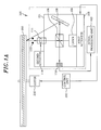
- As shown in Fig. 1A, the holographic ROM system includes a pick-
up unit 100, aholographic medium 200, amotor 210, acontrol unit 300 and asignal processing unit 400. A plurality of data is recorded on theholographic medium 200 by using the angular multiplexing technique. Theholographic medium 200 is rotated by themotor 210 operated under control of thecontrol unit 300 during playback. - The pick-
up unit 100 includes acase 101, afirst actuator 102, alaser source 104, a PBS (polarization beam splitter) 106, an actuatedmirror 108, anaperture 110, anobjective lens 112, asecond actuator 114 and alight receiving unit 116. Provided in thecase 101 are thefirst actuator 102, thelaser source 104, the PBS 106, the actuatedmirror 108 and thelight receiving unit 116. - During playback, the
laser source 104 emits a laser beam with a constant wavelength, e.g., a wavelength of 532 nm. The laser beam of, e.g., only S type of linear polarization is provided to thePBS 106. - The PBS 106, which is manufactured by repeatedly depositing at least two kinds of materials, each having a different refractive index, serves to transmit one type of polarized laser beam, e.g., P-polarized beam, and reflect the other type of polarized laser beam, e.g., S-polarized beam. Therefore, the PBS 106 reflects the reference beam toward the actuated
mirror 108. - The reflected reference beam undergoes another reflection at a predetermined angle by the actuated
mirror 108, thereby being incident upon theholographic medium 200. In order to retrieve and reconstruct holographic data, the angle of incidence of the reference beam toward theholographic medium 200 should be identical to that of a reference beam employed during a recording operation. - When the reference beam reflected at the predetermined angle by the actuated
mirror 108 is irradiated onto theholographic medium 200, the interference pattern recorded in theholographic medium 200 diffracts the reference beam to thereby create a reconstructing beam. - The reconstructing beam travels into the
case 101 via theaperture 110 and theobjective lens 112, and theobjective lens 112 can be moved by thesecond actuator 114. Elements in the pick-up unit 100 can be moved by thefirst actuator 102. Furthermore, thecase 101 is configured not to obstruct the traveling of the light. - After passing through the
objective lens 112, the reconstructing beam is transmitted to the PBS 106 and then is reflected toward thelight receiving unit 116 by the PBS 106. - The reconstructing beam received by the
light receiving unit 116 is reproduced by thesignal processing unit 400. - The holographic ROM system reproduces data, which have been overlappingly recorded at a first angle of incidence on the
holographic medium 200 by using a reference beam having a phase conjugation with respect to the first angle, after which the actuatedmirror 108 should be rotated in order to reproduce data, which have been overlappingly recorded at a second angle of incidence on theholographic medium 200 by using a reference beam having a phase conjugation with respect to the second angle. - Through the repetition of the above processes, the holographic ROM system reproduces the data recorded by the angular multiplexing technique.
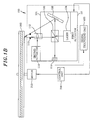
- However, if an angle of incidence of the reference beam toward the
holographic medium 200 is changed, the incidence location thereof on theholographic medium 200 is changed and, accordingly, a radiating point of the reconstructing beam on thehologram medium 200 is also changed, as shown in Fig. 1B. Therefore, the reconstructing beam is deviated from an optical axis of theobjective lens 112, so that a distortion of the reconstructing beam occurs thereby raising a problem of not being able to reproduce the data recorded on theholographic medium 200 exactly. As an extreme case, the reconstructing beam may be totally deviated from theobjective lens 112, which may result in failure to reproduce the data recorded on theholographic medium 200. - It is, therefore, an object of the present invention to provide a holographic apparatus and method including an actuated mirror capable of controlling a reference beam to be incident upon a same location on a holographic medium irrespective of an angle of incidence of the reference beam toward the holographic medium during reconstruction.
- In accordance with one aspect of the invention, there is provided a holographic apparatus including an actuated mirror including: a fixed body having a first piezo-actuator protrudingly installed thereat; a movable body rectilinearly movable and having a second piezo-actuator protrudingly installed thereat; a rotatable body mounting thereon a mirror and rotatably installed at the movable body; and springs for connecting the fixed body and the movable body and connecting the movable body and the rotatable body to enable a rotational movement of the rotatable body and a rectilinear movement of the movable body, wherein a first prominence is installed at the movable body and in contact with a first piezo-actuator; and a second prominence is installed at the rotatable body and in contact with a second piezo-actuator; and wherein the first and the second piezo-actuators are controllable to be expanded or contracted.
- In accordance with another aspect of the invention, there is provided a holographic apparatus including an actuated mirror including: a base; a fixed body fixedly installed on the base and having a first piezo-actuator protrudingly installed thereat; a movable body installed on the base to be rectilinearly movable thereon and having a second piezo-actuator protrudingly installed thereat; a rotatable body rotatably connected to the movable body and mounting thereon a mirror; springs for connecting the fixed body and the movable body and connecting the movable body and the rotatable body to enable a rotational movement of the rotatable body and a rectilinear movement of the movable body; a first prominence installed at the movable body and in contact with a first piezo-actuator; a second prominence installed at the rotatable body and in contact with a second piezo-actuator; and a control unit for either expanding or contracting the first and the second piezo-actuators.
- In accordance with still another aspect of the invention, there is provided a holographic method including the steps of: generating a laser beam; reflecting the laser beam toward an actuated mirror; and reflecting the laser beam by the actuated mirror to be incident on a holographic medium, wherein the actuated mirror changes an angle of incidence of the laser beam toward the holographic medium, and an incidence point of the laser beam on the holographic medium is unchanged though the angle of incidence thereof is changed.
- The above and other objects and features of the present invention will become apparent from the following description of a preferred embodiment given in conjunction with the accompanying drawings, in which:
- Figs. 1A and 1B show a conventional holographic ROM system;
- Fig. 2 illustrates a holographic ROM system in accordance with a preferred embodiment of the present invention; and
- Fig. 3 offers an actuated mirror employed in the holographic ROM system illustrated in Fig. 2 in detail.
-
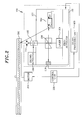
- There are shown in Figs. 2 and 3 a holographic apparatus, e.g., a holographic ROM, and an actuated mirror unit employed therein, respectively, in accordance with a preferred embodiment of the present invention.
- Since the only difference between a holographic apparatus of the present invention and that of the prior art shown in Figs. 1A and 1B lies on an actuated mirror unit, the same names and reference numerals are used to denote identical elements other than the actuated mirror unit, and the detailed description thereof will be omitted.
- As shown in Fig. 2, the holographic apparatus includes a pick-
up unit 100, aholographic medium 200, amotor 210, acontrol unit 300 and asignal processing unit 400. A plurality of data is recorded on theholographic medium 200 by using the angular multiplexing technique. Theholographic medium 200 is rotated by themotor 210 operated under control of thecontrol unit 300 during playback. - The pick-
up unit 100 includes acase 101, afirst actuator 102, alaser source 104, a PBS (polarization beam splitter) 106, an actuatedmirror unit 500, anaperture 110, anobjective lens 112, asecond actuator 114 and alight receiving unit 116. - The actuated
mirror unit 500 in accordance with the present invention is provided with abase 510, afixed body 520, amovable body 530 and arotatable body 540 as illustrated in Fig. 3. - The
base 510 has a shape of, e.g., a rectangular plate, on which thefixed body 520 and themovable body 530 are installed. - The
fixed body 520 is fixedly installed on thebase 510 and has a first piezo-actuator 522 installed at a side surface thereof which faces themovable body 530, wherein a part of the first piezo-actuator 522 is embedded in thefixed body 520 and the remaining part thereof is protruded therefrom. - Furthermore, the
movable body 530 slidably installed on thebase 510 can be rectilinearly moved thereon. Installed at an opposite side surface of themovable body 530 with respect to the side surface thereof facing thefixed body 520 is therotatable body 540 mounting thereon amirror 542. Therotatable body 540 is connected to the opposite side surface of themovable body 530 through apivot 544 serving as a center of gyration. Thepivot 544 allows therotatable body 540 to be rotated. Provided at the opposite side surface of themovable body 530 which faces therotatable body 540 is a second piezo-actuator 532 having the same shape as the first piezo-actuator 522. - Prepared between the
fixed body 520 and themovable body 530 and between themovable body 530 and therotatable body 540 aresprings 550 for collinearly connecting thefixed body 520, themovable body 530 and therotatable body 540. Thesprings 550 enable therotatable body 540 to be rotationally moved and themovable body 530 to be rectilinearly moved. -
Prominences movable body 530 which faces thefixed body 520 and the side surface of therotatable body 540 which faces themovable body 530, respectively. Theprominences actuators - A
control unit 560 controls the first and the second piezo-actuators - Operation of the actuated
mirror unit 500 employed in the holographic apparatus will be explained. - Referring to Fig. 2, a reference beam for reproducing data superimposedly recorded on the
holographic medium 200 is directed toward theholographic medium 200 with a first angle of incidence after begin reflected by the actuatedmirror unit 500. - Subsequently, the
mirror 542 included in the actuatedmirror unit 500 is rotated in a predetermined degree to reconstruct data superimposedly recorded at a second angle of incidence. In such case, according to the prior art, the reference beam may strike an unintended location on theholographic medium 200. However, in accordance with the present invention, the actuatedmirror unit 500 controls the incidence point on theholographic medium 200 by rectilinearly moving themovable body 530 and rotating therotatable body 540 so that the reference beam can strike a wanted location on theholographic medium 200. - By applying a high frequency voltage to the first piezo-
actuator 522, the first piezo-actuator 522 is expanded, thereby allowing themovable body 530 to move. Such expansion of the first piezo-actuator 522 applies pressure to theprominence 533 of themovable body 530, so that themovable body 530 is slidably moved toward therotatable body 540 on thebase 510. At this time, thespring 550 between thefixed body 520 and themovable body 530 is also extended. The destination of themovable body 530 is determined by thecontrol unit 560 such that the incidence point on theholographic medium 200 can completely coincide with a data area to be reconstructed. - In case a high frequency voltage is applied to the second piezo-
actuator 532, the second piezo-actuator 532 may put the pressure on theprominence 543 in a similar manner as described above, by which therotatable body 540 is rotated about thepivot 544 thereby compressing thespring 550 between themovable body 530 and therotatable body 540. The rotational angle of therotatable body 540 is controlled by thecontrol unit 530. - By repetition of the moving and the rotating operations as described above, the holographic apparatus reconstructs a plurality of data recorded by the angular multiplexing technique.
- On the other hand, in case the fist and the second piezo-
actuators control unit 560, themovable body 530 is moved back to an original position by the restitutive force of thespring 550 and therotatable body 540 is also rotated back to an original angular position. - As described above, though the angle of incidence of the reference beam is changed, the actuated
mirror unit 500 enables the reference beam to be incident on a wanted location on theholographic medium 200 by rotating therotatable body 540 and rectilinearly moving themovable body 530, so that the plurality of data can be detected with a high reliability. - As explained hitherto, in the holographic apparatus and method including the actuated mirror in accordance with the present invention, when the holographic medium recorded by the angular multiplexing technique is replayed, e.g., by a holographic player, the incidence point of the reference beam on the holographic medium is not changed despite the variation of the angle of incidence thereof to thereby minimize the distortion of the replayed data.
- While the invention has been shown and described with respect to the preferred embodiments, it will be understood by those skilled in the art that various changes and modifications may be made without departing from the scope of the invention as defined in the following claims.
Claims (8)
- A holographic apparatus comprising an actuated mirror including:wherein a first prominence is installed at the movable body and in contact with a first piezo-actuator; and a second prominence is installed at the rotatable body and in contact with a second piezo-actuator; anda fixed body having a first piezo-actuator protrudingly installed thereat;a movable body rectilinearly movable and having a second piezo-actuator protrudingly installed thereat;a rotatable body mounting thereon a mirror and rotatably installed at the movable body; andsprings for connecting the fixed body and the movable body and connecting the movable body and the rotatable body to enable a rotational movement of the rotatable body and a rectilinear movement of the movable body,
wherein the first and the second piezo-actuators are controllable to be expanded or contracted. - The holographic apparatus of claim 1, wherein the movable body and the fixed body are installed on a base and the movable body is rectilinearly movable on the base.
- The holographic apparatus of claim 1, wherein the rotatable body is connected to the movable body via a pivot serving as a center of gyration.
- The holographic apparatus of claim 1, wherein in case a high frequency voltage is applied to the first and the second piezo-actuators respectively, the first and the second piezo-actuators are expanded respectively.
- The holographic apparatus of claim 1, wherein a laser beam incident on the mirror is reflected toward a wanted location on a holographic medium by a movement of the movable body and a rotation of the rotatable body.
- A holographic apparatus comprising an actuated mirror including:a base;a fixed body fixedly installed on the base and having a first piezo-actuator protrudingly installed thereat;a movable body installed on the base to be rectilinearly movable thereon and having a second piezo-actuator protrudingly installed thereat;a rotatable body rotatably connected to the movable body and mounting thereon a mirror;springs for connecting the fixed body and the movable body and connecting the movable body and the rotatable body to enable a rotational movement of the rotatable body and a rectilinear movement of the movable body;a first prominence installed at the movable body and in contact with a first piezo-actuator;a second prominence installed at the rotatable body and in contact with a second piezo-actuator; anda control unit for either expanding or contracting the first and the second piezo-actuators.
- The holographic apparatus of claim 6, wherein in case a high frequency voltage is applied to the first and the second piezo-actuators respectively, the first and the second piezo-actuators are expanded respectively.
- A holographic method comprising the steps of:wherein the actuated mirror changes an angle of incidence of the laser beam toward the holographic medium, and an incidence point of the laser beam on the holographic medium is unchanged though the angle of incidence thereof is changed.generating a laser beam;reflecting the laser beam toward an actuated mirror; andreflecting the laser beam by the actuated mirror to be incident on a holographic medium,
Applications Claiming Priority (2)
| Application Number | Priority Date | Filing Date | Title |
|---|---|---|---|
| KR2003035034 | 2003-05-31 | ||
| KR10-2003-0035034A KR100536711B1 (en) | 2003-05-31 | 2003-05-31 | Drive mirror that use holographic rom |
Publications (2)
| Publication Number | Publication Date |
|---|---|
| EP1482488A2 true EP1482488A2 (en) | 2004-12-01 |
| EP1482488A3 EP1482488A3 (en) | 2006-01-04 |
Family
ID=33129056
Family Applications (1)
| Application Number | Title | Priority Date | Filing Date |
|---|---|---|---|
| EP04012605A Withdrawn EP1482488A3 (en) | 2003-05-31 | 2004-05-27 | Holographic apparatus having an actuated mirror and corresponding method |
Country Status (5)
| Country | Link |
|---|---|
| US (1) | US7109640B2 (en) |
| EP (1) | EP1482488A3 (en) |
| JP (1) | JP2004362741A (en) |
| KR (1) | KR100536711B1 (en) |
| CN (1) | CN1307630C (en) |
Families Citing this family (5)
| Publication number | Priority date | Publication date | Assignee | Title |
|---|---|---|---|---|
| WO2008001416A1 (en) | 2006-06-26 | 2008-01-03 | Fujitsu Limited | Hologram recording device and hologram recording/reproducing method |
| JPWO2008001434A1 (en) * | 2006-06-28 | 2009-11-26 | 富士通株式会社 | Hologram recording apparatus and hologram recording method |
| JP2009545781A (en) * | 2006-08-03 | 2009-12-24 | インフェイズ テクノロジーズ インコーポレイテッド | Small single-actuator scanner for angle multiplexing with circularization and pitch correction functions |
| JPWO2009075024A1 (en) | 2007-12-11 | 2011-04-28 | 富士通株式会社 | Hologram recording device |
| CN109741765B (en) * | 2017-10-27 | 2021-03-19 | 青岛泰谷光电工程技术有限公司 | Holographic storage system |
Citations (5)
| Publication number | Priority date | Publication date | Assignee | Title |
|---|---|---|---|---|
| JPS63298208A (en) * | 1987-05-29 | 1988-12-06 | Nippon Telegr & Teleph Corp <Ntt> | Movable mirror mechanism |
| US5892597A (en) * | 1991-08-29 | 1999-04-06 | Fujitsu Limited | Holographic recording apparatus and holographic optical element |
| US20020054403A1 (en) * | 2000-05-11 | 2002-05-09 | Monaghan Brian J. | Hologram production technique |
| US20020176127A1 (en) * | 2001-05-23 | 2002-11-28 | Garner Harold R. | Digital micro-mirror holographic projection |
| JP2004074166A (en) * | 2002-08-09 | 2004-03-11 | Hitachi Via Mechanics Ltd | Optical scanner and laser beam machine |
Family Cites Families (12)
| Publication number | Priority date | Publication date | Assignee | Title |
|---|---|---|---|---|
| US4736132A (en) * | 1987-09-14 | 1988-04-05 | Rockwell International Corporation | Piezoelectric deformable mirrors and gratings |
| JPH0668484A (en) * | 1992-08-20 | 1994-03-11 | Sony Corp | Optical pickup device |
| US20020005679A1 (en) * | 1997-07-15 | 2002-01-17 | Virgil B. Elings | Method and apparatus for improving a flexure stage |
| JPH11213439A (en) * | 1998-01-27 | 1999-08-06 | Olympus Optical Co Ltd | Optical pickup device |
| US6252333B1 (en) * | 1998-02-20 | 2001-06-26 | Seiko Instruments Inc. | Stage utilizing ultrasonic motor and electronic equipment and printer utilizing the stage |
| US6157473A (en) * | 1998-12-31 | 2000-12-05 | Daewoo Electronics Co., Ltd. | Holographic storage system incorporated therein a parabolic mirror |
| KR100327367B1 (en) * | 1999-05-26 | 2002-03-06 | 구자홍 | micro-mirror device and optical pick-up system using the same |
| US6246052B1 (en) * | 1999-09-20 | 2001-06-12 | Veeco Instruments, Inc. | Flexure assembly for a scanner |
| JP2001307355A (en) | 2000-02-16 | 2001-11-02 | Fujitsu Ltd | Optical disk device and galvano-mirror |
| KR20020037371A (en) * | 2000-08-02 | 2002-05-18 | 마츠시타 덴끼 산교 가부시키가이샤 | Optical pickup device |
| US7130501B2 (en) * | 2003-02-19 | 2006-10-31 | Will Peter M | Meso-scale strictly non-blocking N×N optical crossbar switch using precision servo controls |
| KR20040103115A (en) * | 2003-05-31 | 2004-12-08 | 주식회사 대우일렉트로닉스 | Apparatus for detecting bean in a holographic rom system |
-
2003
- 2003-05-31 KR KR10-2003-0035034A patent/KR100536711B1/en not_active IP Right Cessation
-
2004
- 2004-03-30 JP JP2004099767A patent/JP2004362741A/en active Pending
- 2004-05-25 US US10/852,164 patent/US7109640B2/en not_active Expired - Fee Related
- 2004-05-27 EP EP04012605A patent/EP1482488A3/en not_active Withdrawn
- 2004-05-31 CN CNB200410047311XA patent/CN1307630C/en not_active Expired - Fee Related
Patent Citations (5)
| Publication number | Priority date | Publication date | Assignee | Title |
|---|---|---|---|---|
| JPS63298208A (en) * | 1987-05-29 | 1988-12-06 | Nippon Telegr & Teleph Corp <Ntt> | Movable mirror mechanism |
| US5892597A (en) * | 1991-08-29 | 1999-04-06 | Fujitsu Limited | Holographic recording apparatus and holographic optical element |
| US20020054403A1 (en) * | 2000-05-11 | 2002-05-09 | Monaghan Brian J. | Hologram production technique |
| US20020176127A1 (en) * | 2001-05-23 | 2002-11-28 | Garner Harold R. | Digital micro-mirror holographic projection |
| JP2004074166A (en) * | 2002-08-09 | 2004-03-11 | Hitachi Via Mechanics Ltd | Optical scanner and laser beam machine |
Non-Patent Citations (2)
| Title |
|---|
| PATENT ABSTRACTS OF JAPAN vol. 013, no. 127 (P-848), 29 March 1989 (1989-03-29) -& JP 63 298208 A (NIPPON TELEGR & TELEPH CORP <NTT>), 6 December 1988 (1988-12-06) * |
| PATENT ABSTRACTS OF JAPAN vol. 2003, no. 12, 5 December 2003 (2003-12-05) -& JP 2004 074166 A (HITACHI VIA MECHANICS LTD), 11 March 2004 (2004-03-11) * |
Also Published As
| Publication number | Publication date |
|---|---|
| EP1482488A3 (en) | 2006-01-04 |
| KR100536711B1 (en) | 2005-12-14 |
| KR20040103113A (en) | 2004-12-08 |
| CN1307630C (en) | 2007-03-28 |
| US7109640B2 (en) | 2006-09-19 |
| CN1573986A (en) | 2005-02-02 |
| JP2004362741A (en) | 2004-12-24 |
| US20040240008A1 (en) | 2004-12-02 |
Similar Documents
| Publication | Publication Date | Title |
|---|---|---|
| JP5466833B2 (en) | Method for performing page-based holographic recording and readout | |
| JP4991872B2 (en) | Configuration of monocular holographic data storage system | |
| US7548358B2 (en) | Phase conjugate reconstruction of a hologram | |
| US7209270B2 (en) | Method and apparatus for phase correlation holographic drive | |
| US6825960B2 (en) | System and method for bitwise readout holographic ROM | |
| US7804758B2 (en) | Holographic information recording/reproducing apparatus | |
| JP4997254B2 (en) | A flexure-based compact scanner for angle multiplexing | |
| JP4787097B2 (en) | Holographic memory reproduction system using servo | |
| US7848204B2 (en) | Holographic storage and regeneration system having servo mechanism | |
| EP1531462B1 (en) | Holographic recording and reconstructing apparatus and mask for use therein | |
| US7649661B2 (en) | Holographic storage device having a reflective layer on one side of a recording layer | |
| EP1526517B1 (en) | Apparatus and method for controlling tracking and focusing servo in a holographic digital data storage system | |
| EP1605443B1 (en) | Holographic data recording apparatus and method | |
| JP6667177B2 (en) | Hologram recording / reproducing method and hologram recording / reproducing apparatus | |
| US7109640B2 (en) | Holographic apparatus and method adopting actuated mirror | |
| US7193757B2 (en) | Angle multiplexing holographic storage device and method | |
| US7027196B2 (en) | Tilt servo apparatus for use in ROM system | |
| JP3693990B2 (en) | Optical information recording apparatus and optical information reproducing apparatus | |
| KR20120040674A (en) | Replication and formatting method and system for bit-wise holographic storage |
Legal Events
| Date | Code | Title | Description |
|---|---|---|---|
| PUAI | Public reference made under article 153(3) epc to a published international application that has entered the european phase |
Free format text: ORIGINAL CODE: 0009012 |
|
| AK | Designated contracting states |
Kind code of ref document: A2 Designated state(s): AT BE BG CH CY CZ DE DK EE ES FI FR GB GR HU IE IT LI LU MC NL PL PT RO SE SI SK TR |
|
| AX | Request for extension of the european patent |
Extension state: AL HR LT LV MK |
|
| PUAL | Search report despatched |
Free format text: ORIGINAL CODE: 0009013 |
|
| AK | Designated contracting states |
Kind code of ref document: A3 Designated state(s): AT BE BG CH CY CZ DE DK EE ES FI FR GB GR HU IE IT LI LU MC NL PL PT RO SE SI SK TR |
|
| AX | Request for extension of the european patent |
Extension state: AL HR LT LV MK |
|
| 17P | Request for examination filed |
Effective date: 20060407 |
|
| AKX | Designation fees paid |
Designated state(s): DE FR GB IT NL |
|
| 17Q | First examination report despatched |
Effective date: 20070719 |
|
| STAA | Information on the status of an ep patent application or granted ep patent |
Free format text: STATUS: THE APPLICATION IS DEEMED TO BE WITHDRAWN |
|
| 18D | Application deemed to be withdrawn |
Effective date: 20071130 |