BACKGROUND OF THE INVENTION
-
The present invention relates to an optical device that
converts the advancing direction of light emitted by an area
light emitting device, an area light apparatus that includes
the optical device and the area light emitting device, and a
display that uses the area light apparatus as a backlight.
-
For example, Japanese Laid-Open Patent Publication No.
4-67016 discloses a light apparatus 1000 shown in Fig. 17.
The light apparatus 1000 includes a light source 100, which is
a fluorescent tube, a reflector box 200 the inner surface of
which is specular or white, an opaline diffusion plate 300, a
transparent prism sheet 400 functioning as an optical device,
and a transmissive display panel 500. The prism sheet 400 has
on a side triangle pole shaped prisms arranged parallel to one
another.
-
Light emitted from the light source 100 either directly
reaches the diffusion plate 300 or reaches the diffusion plate
300 after being reflected by the inner surfaces of the
reflector box 200. The light is then converted into a uniform
area light by the diffusion plate 300. After light passes
through the diffusion plate 300, components of the light that
are diffused in the vertical direction are gathered by the
prism sheet 400 in a direction of the normal to the display
surface of the display panel 500, and reach the display panel
500. Therefore, compared to a case where no prism sheet 400
is provided, a greater amount of light reaches the display
panel in a frontward direction, which permits an image having
a high brightness to be displayed.
-
Since the prism sheet 400 gathers light and changes the
paths of light only linearly, there have been proposed
techniques for two-dimensionally gathering light and changing
paths of light.
-
For example, a display 1010 shown in Fig. 18 has, in
addition to the configuration of the light apparatus 1000 of
Fig. 17, another prism sheet 400a located between the prism
sheet 400 and the diffusion plate 300. The prisms on the
prism sheet 400a extend in a direction orthogonal to the
prisms on the prism sheet 400. In the light that exits the
diffusion plate 300 (diffused light), light components in one
direction (left-right direction as viewed in the drawing) are
gathered by the lower prism sheet 400a, and light components
in a direction perpendicular to the left-and-right direction
(up-down direction as viewed in the drawing) are gathered by
the upper prism sheet 400.
-
The components of light produced by the light source 100
are two-dimensionally gathered and reach the display panel 500.
Accordingly, compared to the light apparatus 1000 shown in Fig.
17, a greater amount of light is gathered in a specific
direction (a direction of the normal to the display panel 500),
which further increases the brightness of the display.
-
However, since the display 1010 of Fig. 18 requires the
two prism sheets 400, 400a, the display 1010 has a greater
thickness a greater number of components than the light
apparatus 1000 of Fig. 17. This makes the design and
production difficult.
-
Japanese Laid-Open Patent Publication No. 6-308485
discloses a display 1020 having a single prism sheet 401 as
shown in Fig. 19. The prism sheet 401 two-dimensionally
gathers light. The display 1020 includes the light source 100,
the reflector box 200, the diffusion plate 300, the display
panel 500, and the prism sheet 401. The prism sheet 401 is
located between the diffusion plate 300 and the display panel
500. On one side of the prism sheet 401, square pyramid
shaped prisms are arranged in a grid pattern.
-
Fig. 20 is a partial front view showing the prism sheet
401 of Fig. 19. Figs. 20a and 20b are cross-sectional views
of the prism sheet 401 taken along lines 20a-20a and 20b-20b,
respectively.
-
The shape of the square pyramid of each prism on the
prism sheet 401 is designed based only on components of light
that enter the
prism sheet 401 through an incident surface and
are emitted without being reflected. Fig. 21 shows the path
of light in the
prism sheet 401 in Fig. 20a. As shown in Fig.
21, each of
slopes 401b forming the pyramids is designed to be
inclined by an angle 5 (prism angle 5) with respect to a
plane parallel to a plane 401a, which is an incident surface,
based on Snell laws of refraction represented by the following
equations (formula 1).
2 = sin-1(sin1/n1) (n1 is the index of refraction of
the prism sheet)
3 = 5 - 2
-
In Fig. 21, a ray L1 enters the prism sheet 401 from the
air (index of refraction no = 1) at an angle 1 with respect
to the normal S1 to the plane 401a. The ray L1 is refracted
at the interface between the air and the plane 401a at an
angle 2, then advances through the prism sheet 401. The ray
L1 reaches a prism plane 401b at an angle 3 with respect to
the normal S2 to the prism plane 401b, and is refracted at an
angle 4 with respect to a line S3 that is parallel to the
normal S1 to the plane 401a. The light L1 then exits into the
air.
-
For example, if the index of refraction of the prism
sheet 401 is 1.50 and the ray L1 reaches the plane 401a at an
angle (incidence angle) 1 of 45°, the angle of the slope 401b
is computed by substituting these values into the formula 1.
As shown in Fig. 22, the angle of the slope 401b is 25° with
respect to the normal S1 to the plane 401a.
-
For example, when prism sheets of the indexes of
refraction of the following list are employed, the angle of
the slope 401b with respect to the normal S1 to the plane 401a
are set as shown below.
-
When the index of refraction is 1.40, the angle of the
slope 401b is set to 17°.
When the index of refraction is 1.45, the angle of the
slope 401b is set to 20.5°.
When the index of refraction is 1.60, the angle of the
slope 401b is set to 32°.
When the index of refraction is 1.64, the angle of the
slope 401b is set to 34°.
When the index of refraction is 1.70, the angle of the
slope 401b is set to 37.5°.
-
On the other hand, materials for optical devices such as
prism sheets are typically selected in terms of transparency,
workability, and weight. For example, materials for optical
devices include polymethyl-methacrylate (index of refraction n
= 1.49), Arton (n = 1.51, registered trademark), Zeonor (n =
1.52, registered trademark), glass (n = 1.53), polyvinyl
chloride (n = 1.54), polyethylene terephthalate (n =1.57),
polycarbonate (n = 1.58), polystyrene (n = 1.59).
Alternatively, members formed by coating these materials may
be employed. The index of refraction of applicable material
is in a range between 1.40 and 1.70, inclusive.
-
Therefore, if a prism sheet is designed using the above
formula 1 without considering properties such as reflection
properties, although depending on the type of the employed
material, the angle of each of the slopes forming the pyramids
(projections) with respect to the normal to an incident
surface is in a range between 17° and 37.5°, inclusive.
-
The inventors of the present invention performed
simulations using an organic electroluminescent device having
an isotropic light emission property and a reflection property
as a light source, and found out that, if a prism sheet is
formed according to a design using the above formula 1, the
brightness cannot be sufficiently increased. The reason for
this is considered that some of light that enters the prism
sheet was reflected in the prism sheet toward the light source
and reached the light source, and this portion of light was
reflected by the reflector plate of the light source toward
the prism sheet and re-entered the prism sheet.
SUMMARY OF THE INVENTION
-
A first objective of the present invention is to provide
an optical device that has an improved optical properties
compared to conventional optical devices.
-
A second objective of the present invention is to
provide an optical device that is different from the optical
device shown in the prior art section and has the same or
superior characteristics as that of the prior art optical
devices.
-
A third objective of the present invention is to provide
a light apparatus having such an optical device.
-
A forth objective of the present invention is to provide
a display having such a light apparatus as a backlight.
-
To attain the above object, the present invention
provides an optical device for changing an optical path of
light that reaches the device. The optical device is
transparent. The optical device has an incident surface and a
light exit surface located at an opposite side from the
incident surface. The light exit surface defines a plurality
of projections and/or recesses. The projections project away
from the incident surface. The recesses are dented toward the
incident surface. Sections of the light exit surface that
define projections and/or recesses include side faces of
pyramids or truncated pyramids. Each of the pyramids and the
truncated pyramids has a bottom that is an imaginary plane
substantially parallel to the incident surface. The side
faces of each of the pyramids and the truncated pyramids are
slopes. At least one of the slopes is inclined at a
predetermined angle relative to the normal to the incident
surface. The predetermined angle is in a range greater than
17° and less than 60°.
-
In this embodiment, slopes refer to slopes of a pyramid
and do not include the bottom of the pyramid. Each slope is
triangular.
-
The present invention also provides an optical device
for changing an optical path of light that reaches the device.
The optical device is transparent. The optical device has an
incident surface and a light exit surface located at an
opposite side from the incident surface. The light exit
surface defines a plurality of projections and/or recesses.
The projections project away from the incident surface. The
recesses are dented toward the incident surface. Sections of
the light exit surface that define projections and/or recesses
include side faces of cones or truncated cones. Each of the
cones and the truncated cones has a bottom that is an
imaginary plane substantially parallel to the incident surface.
The side face of each cone or each truncated cone is inclined
at a predetermined angle relative to the normal to the
incident surface. The predetermined angle is in a range
greater than 30° and less than 55°.
-
The side surface of a cone refers to the surface of the
cone except for the bottom.
-
Other aspects and advantages of the invention will become
apparent from the following description, taken in conjunction
with the accompanying drawings, illustrating by way of example
the principles of the invention.
BRIEF DESCRIPTION OF THE DRAWINGS
-
The invention, together with objects and advantages
thereof, may best be understood by reference to the following
description of the presently preferred embodiments together
with the accompanying drawings in which:
- Fig. 1 is an exploded perspective view illustrating a
first area light apparatus according to one embodiment of the
present invention;
- Fig. 2 is a plan view for explaining the structure of
the first prism sheet in the first area light apparatus;
- Fig. 2(a) is a cross-sectional view taken along line 2a-2a
of Fig. 2;
- Fig. 2(b) is a cross-sectional view taken along line 2b-2b
of Fig. 2;
- Fig. 3 is a plan view illustrating another prism sheet
according to the embodiment of Fig. 1;
- Fig. 3(a) is a cross-sectional view taken along line 3a-3a
of Fig. 3;
- Fig. 3(b) is a cross-sectional view taken along line 3b-3b
of Fig. 3;
- Fig. 4 is an exploded perspective view illustrating a
prior art area light apparatus;
- Fig. 5 is an exploded perspective view a prior art area
light apparatus that is different from the area light
apparatus shown in Fig. 4;
- Fig. 6 is a cross-sectional view illustrating a first
prism sheet according to a modification;
- Fig. 7 is a graph showing the relative ratio of
brightness when the area of a upper surface relative to the
area of a bottom is changed in an area light apparatus having
the prism sheet shown in Fig. 6;
- Fig. 8 is a plan view showing a first prism sheet
according to a modification;
- Fig. 8(a) is a cross-sectional view taken along line 8a-8a
of Fig. 8;
- Fig. 8(b) is a cross-sectional view taken along line 8b-8b
of Fig. 8;
- Fig. 9 is a plan view showing a first prism sheet
according to a modification;
- Fig. 9(a) is a cross-sectional view taken along line 9a-9a
of Fig. 9;
- Fig. 9(b) is a cross-sectional view taken along line 9b-9b
of Fig. 9;
- Fig. 10 is a plan view showing a first prism sheet
according to a modification;
- Fig. 10(a) is a cross-sectional view taken along line
10a-10a of Fig. 10;
- Fig. 10(b) is a cross-sectional view taken along line
10b-10b of Fig. 10;
- Fig. 11 is a plan view illustrating a second prism sheet
in a second area light apparatus;
- Fig. 11(a) is a cross-sectional view taken along line
11a-11a of Fig. 11;
- Fig. 11(b) is a cross-sectional view taken along line
11b-11b of Fig. 11;
- Fig. 12 is a plan view showing another prism sheet
according to a modification;
- Fig. 12(a) is a cross-sectional view taken along line
12a-12a of Fig. 12;
- Fig. 12(b) is a cross-sectional view taken along line
12b-12b of Fig. 12;
- Fig. 13 is a first diagram for explaining extraction of
light in the prism sheet according to the first embodiment;
- Figs. 14(a) and 14(b) are second diagrams for explaining
extraction of light in the prism sheet according to the first
embodiment;
- Figs. 15(a) and 15(b) are third diagrams for explaining
extraction of light in the prism sheet according to the first
embodiment;
- Figs. 16(a) and 16(b) are fourth diagrams for explaining
extraction of light in the prism sheet according to the first
embodiment;
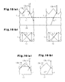
- Fig. 17 is an exploded perspective view illustrating a
prior art display;
- Fig. 18 is an exploded perspective view illustrating
another prior art display;
- Fig. 19 is an exploded perspective view illustrating
another prior art display;
- Fig. 20 is a plan view showing the prism sheet in the
display of Fig. 19;
- Fig. 20(a) is a cross-sectional view taken along line
20a-20a of Fig. 20;
- Fig. 20(b) is a cross-sectional view taken along line
20b-20b of Fig. 20;
- Fig. 21 is a cross-sectional view showing the path of
light in the prism sheet of Fig. 20 based on Snell laws of
refraction; and
- Fig. 22 is a cross-sectional view showing the path of
light in the prism sheet of Fig. 20 based on Snell laws of
refraction.
-
DETAILED DESCRIPTION OF THE PREFERRED EMBODIMENTS
-
Several embodiments of the present invention will now be
described with reference to the drawings. Like or the same
reference numerals are given to those components that are like
or the same in the drawings. A first area light apparatus 101
will now be described.
-
As shown in Fig. 1, the first area light apparatus 101
includes an optical device, which is a prism sheet 1, and an
area light-emitting device, which is an organic
electroluminescent device (organic EL device) 2.
-
The organic EL device 2 has a transparent substrate and
is formed by consecutively laminating a transparent electrode
22, an organic layer 23, and a reflecting electrode 24 on the
transparent substrate 21. The transparent substrate 21 is
formed, for example, of glass or an acrylic resin. The
transparent electrode 22 is formed, for example, of ITO. The
organic layer 23 contains organic light-emitting material such
as Alq3 and Ir(ppy)3. The reflecting electrode 24 is formed,
for example, of Al.
-
When a current is supplied between the transparent
electrode 22 and the reflecting electrode 24, recombination of
holes and electrons occurs, which generates excitons.
Accordingly, the organic light-emitting material is excited.
Then, when returning to the ground state, the excited organic
light-emitting material emits light. The organic EL device 2
has an isotropic light emission property. That is, light
generated at the organic light-emitting material is directed
to all the directions.
-
The reflecting electrode 24 reflects light directed from
the organic layer 23 to the reflecting electrode 24 and light
that has been reflected by the prism sheet 1 and reaches the
organic EL device 2 toward the prism sheet 1. The reflecting
electrode 24 provides the organic EL device 2 with a
reflection property.
-
The prism sheet 1 has an incident surface 11 and a light
exit surface 12 located at an opposite side from the incident
surface 11. The organic EL device 2 has the light extracting
surface 25, which is a surface of the transparent substrate 21
that faces the incident surface 11. The light extracting
surface 25 and the incident surface 11 are arranged to be
parallel to each other.
-
In this specification, isotropic light emission property
refers to a property in which the brightness in the same
direction with respect to the normal to a light extracting
surface of an area light-emitting device is substantially
uniform. The reflection property refers to a property in
which light from an optical device is reflected back to the
optical device.
-
The isotropic light emission property of the organic EL
element 2 is preferably designed such that the number of
luminous fluxes in a range between 30° and 60°, inclusive,
more preferably, in a range between 40° and 50°, inclusive,
and most preferably, in a range about 45° with respect to the
normal to a light extracting surface 25 is the greatest
compared to the amount of light in other directions. Such a
device is formed by properly designing and selecting the shape
of the substrate, thickness of each layer, and the materials
of the organic EL element 2.
-
The light exit surface 12 of the prism sheet 1 defines
square pyramid shaped projections 13, which project away from
the incident surface 11. A section of the light exit surface
12 that defines each projection 13 includes side faces of the
corresponding pyramid. The bottom of each pyramid has a
bottom 13a, which is an imaginary plane substantially parallel
to the incident plane 11. The side faces are formed with
slopes 13b. In this embodiment, the bottom 13a of each
projection 13 is substantially square, and is located in an
imaginary plane that lies substantially parallel to the
incident surface 11. The slopes 13b of each projection 13
form part of the light exit surface 12.
-
The imaginary plane contains the points and sides
forming the bottom of each projection 13. The prism sheet 1
may be configured such that an imaginary plane that contains
the bottom of at least one of the projections 13 may be
displaced from the imaginary plane that contains the bottoms
of the other projections 13.
-
The inventors of the present invention performed ray
tracking simulations by Monte Carlo method. Through the
simulations, the inventors computed changes of front
brightness of the first area light apparatus (the brightness
in a direction of the normal to the incident surface 11) when
the angle of slopes 13b of the projections 13 were varied.
The conditions of the simulations are shown below.
-
In this specification, the angle defined by the normal
and each slope 13b refers to the smallest angle in the angles
defined by the normal and lines on the slope 13b. In this
embodiment, the angle defined by the normal and each slope 13b
refers to an angle defined by the normal to the incident
surface 11 and a line in the slope 13b that includes the peak
of the slope 13b, or the peak of the corresponding pyramid,
and perpendicularly intersects the corresponding bottom 13a.
<Example 1>
-
The organic EL device 2 and the prism sheet 1 are square
plates each side of which is 5 cm long.
-
The distance between the light extracting surface 25 and
the incident surface 11 is 10 µm.
-
The distance between the light extracting surface 25 and
the reflecting electrode 24 is 500 µm.
-
A square plane that is away from the peak of each
projection 13 by 10 µm and parallel to the light extracting
surface 25 is set as a measurement plane. The sides of the
measurement plane is 5 cm long each.
-
When projected onto a plane containing the light
extracting surface 25, the shape of the measurement plane and
the shape of the prism sheet 1 match the shape of the light
extracting surface 25.
-
The measurement plane has one million rays.
-
The projections 13 have identical shapes. Each bottom
13a of each projection 13 is 100 µm long.
-
The index of refraction of the prism sheet 1 is 1.50.
-
Each bottom 13a is common to the corresponding adjacent
pair of projections 13 (pyramids). However, the outer bottom
13a of each outermost projection 13 is not common to any other
projections 13.
-
In Fig. 2, an angle defined by each slope 13b of the
projections 13 and the normal 11H to the incident surface 11
is referred to as an angle . The brightness in a direction
of the normal 11H to the incident surface 11, or the front
brightness, was simulated while varying the angle as shown
in Table 1.
-
The results are shown in Table 1. In Table 1, the
brightness is expressed as a front brightness ratio
(brightness ratio) with respect to the brightness in a
direction of the normal to the light extracting surface 25 of
the organic EL device 2, that is, with respect to the front
brightness.
-
A first prism sheet 1a shown in Fig. 3 is a
modifications of the first prism sheet 1 shown in Fig. 2. The
first prism sheet 1a has cone shaped projections 14. Each
projection 14 has a circular bottom 14a the diameter of which
is 100 µm. The projections 14 are arranged such that each
adjacent pair of the bottoms 14a contact each other. The
projections 14 are arranged in a hexagonal closest packed
structure. The other configurations are the same as those of
the first area light apparatus shown in Fig. 1. Regarding the
first prism sheet 1a, an angle defined by each slope 14b of
the projections 14 and the normal 11H to the incident surface
11 was varied as shown in Table 2 below, and the brightness in
a direction of the normal to the incident surface was
simulated.
-
The results are shown in Table 2. In Table 2 also, the
brightness is expressed as the front brightness of the
light
extracting surface 25 of the
organic EL device 2, that is, as
a ratio (front brightness ratio) with respect to the front
brightness of an area light apparatus that includes only the
organic EL device 2.
| Angle , Front Brightness Ratio, and Magnitude of Front Brightness Ratio (Proportion) in each Angle with respect to Front Brightness Ratio when Angle is 45°, in Prism Sheet having Index of Refraction of 1.50 (n = 1.50) |
| Angle (deg) | Front Brightness Ratio | Proportion (%) |
| 5.0 | 0.76 | 45 |
| 10.0 | 0.76 | 45 |
| 15.0 | 0.92 | 54 |
| 20.0 | 1.07 | 63 |
| 25.0 | 1.20 | 71 |
| 30.0 | 1.18 | 70 |
| 35.0 | 1.26 | 75 |
| 40.0 | 1.41 | 83 |
| 42.5 | 1.55 | 92 |
| 43.0 | 1.60 | 95 |
| 43.5 | 1.61 | 95 |
| 44.0 | 1.65 | 98 |
| 44.5 | 1.66 | 98 |
| 45.0 | 1.69 | 100 |
| 45.5 | 1.68 | 99 |
| 46.0 | 1.65 | 98 |
| 46.5 | 1.57 | 93 |
| 47.5 | 1.43 | 85 |
| 50.0 | 1.34 | 79 |
| 55.0 | 1.10 | 65 |
| 60.0 | 1.01 | 60 |
| 65.0 | 0.98 | 58 |
| 70.0 | 0.98 | 58 |
| 75.0 | 0.98 | 58 |
| 80.0 | 0.98 | 58 |
| 85.0 | 0.99 | 59 |
| Angle defined by Slope 14b of Cones and Normal 11H to Incident surface, Front Brightness Ratio, and Magnitude of Front Brightness Ratio (Proportion) in each Angle with respect to Front Brightness when Angle is 45° |
| Angle (deg) | Front Brightness Ratio | Proportion (%) |
| 10 | 1.05 | 74 |
| 20 | 1.04 | 73 |
| 25 | 1.21 | 85 |
| 30 | 1.31 | 92 |
| 35 | 1.21 | 85 |
| 40 | 1.27 | 89 |
| 42.5 | 1.30 | 92 |
| 44 | 1.37 | 96 |
| 45 | 1.42 | 100 |
| 46 | 1.39 | 98 |
| 47.5 | 1.34 | 95 |
| 50 | 1.31 | 92 |
| 55 | 1.08 | 76 |
| 60 | 1.00 | 71 |
| 70 | 0.97 | 68 |
| 80 | 0.98 | 69 |
(Evaluations)
-
According to Snell laws of refraction represented by the
formula 1, the front brightness is expected to be maximized
when the angle defined by each slope 13b of the projections 13
and the normal 11H to the incident surface 11 or the angle
defined by each slope 14b of the projections 14 and the normal
11H is 25°. However, as obvious from Tables 1 and 2,
regardless whether the projections were shaped as square
pyramids or cones, there existed angles at which the front
brightness was greater than the case of the slope angle of 25°.
That is, the inventors of the present invention found out that
at certain angles of slopes of projections, the front
brightness is increased to a level that cannot be achieved by
conventional optical designs in which reflection property is
not taken into consideration. In other words, the inventors
found out requirements for prism sheets and area light
apparatuses that exert superior optical properties. The
evaluations will now be described in more details.
[Evaluation 1]
-
Referring to Table 1, when the
slopes 13b of the
projections 13 are formed to satisfy the following requirement
(1-1), the front brightness is higher than that in a case of
an angle of 25°, where the front brightness is expected to be
maximized when a design according to Snell laws without
considering the reflection property is applied. That is, when
the slope angle was set in any of the following angle ranges,
substantially favorable optical properties (the property of
changing path of rays and the property for gathering light)
were obtained.
- (1-1) An angle greater than 30° and less than 55°.
When the angle of the slopes 13b of the projections 13
are designed to satisfy any of the following requirements (1-2)
to (1-5), the front brightness is greater than the case
where the slope angle is 25°. The prism sheet and the area
light apparatus according to this embodiment have superior
optical properties.
- (1-2) An angle in a range no less than 35° and less than
55°.
- (1-3) An angle in a range no less than 35° and no more
than 50°.
- (1-4) An angle in a range greater than 30° and no more
than 50°.
- (1-5) An angle in a range ±7° with respect to 45°.
-
(Evaluation 2)
-
As a comparison example, a commercially available prism
sheet 10a shown in Fig. 4 was used. The prism sheet 10a
includes an incident surface 110a and triangle pole shaped
prisms 130a arranged parallel to one another. Under the
conditions of the above simulations, simulations were
performed for the front brightness of an area light apparatus
that uses the prism sheet 10a. As a result, the front
brightness was 1.30. The conditions of the simulations are
shown below.
-
The index of refraction of the prism sheet 10a is 1.60.
-
The angle of each slope 130a-1 of the triangle pole
(prism) with respect to the normal to the incident surface
110a is 45°. The angle of 45° is an angle in Table 1 that is
defined by the normal to the incident surface and the slope of
the pyramids or cones at which angle the front brightness is
maximized.
-
The conditions other than the ones listed, for example,
the light emitting property and the reflection property of the
organic EL device 2, were the same as those in the previous
simulation.
-
The comparison between the simulation results of the
comparison examples of Fig. 4 and the simulation results of
Table 1 shows that setting the range of the angle of the
slopes 13b of the
projections 13 to satisfy the following
requirement (2-1) made the front brightness greater than that
of the comparison example of Fig. 4.
- (2-1) An angle in a range greater than 35° and less than
55°.
Also, when the angle of the slopes 13b of the
projections 13 was set to satisfy any of the following
requirements (2-2) to (2-5), the prism sheet and the area
light apparatus exerted optical properties superior to the
comparison example of Fig. 4.
- (2-2) An angle in a range greater than 35° and no more
than 50°.
- (2-3) An angle in a range no less than 40° and less than
55°.
- (2-4) An angle in a range no less than 40° and no more
than 50°.
- (2-5) An angle in a range ±5° with respect to 45°.
-
(Evaluation 3)
-
Fig. 5 shows an area light apparatus of another
comparison example. The light apparatus of Fig. 5 is formed
by stacking two prism sheets 10a, 10b that are the same as the
prism sheet shown in Fig. 4 used in Evaluation (2). The prism
sheets 10a, 10b have triangle pole shaped prisms 130a, 130b,
respectively. The prism sheets 10a, 10b are stacked such that
the prisms 130a, 130b lie perpendicular to each other.
According to the results of the simulation of Fig. 5, the
front brightness was 1.50. Except for the above condition
that two sheets are stacked such that the prisms are arranged
orthogonal to each other, the other conditions of the
simulation were the same as those in the simulation of the
comparison example in Evaluation (2).
-
As obvious from the comparison example and Table 1, in
an angle range that satisfies the following requirement (3-1),
the first area light apparatus of the present embodiment had a
greater front brightness than that of the area light apparatus
shown in Fig. 5. That is, when the slope angle was set in the
following angle ranges, a light gathering property (optical
property) superior to that of conventional apparatuses was
obtained.
- (3-1) An angle in a range greater than 40° and less than
47.5°.
Also, when the angle of the slopes 13b of the
projections 13 was set to satisfy any of the following
requirements (3-2) to (3-7), the prism sheet and the area
light apparatus exerted optical properties superior to the
area light apparatus shown of Fig. 5.
- (3-2) An angle in a range greater than 40° and no more
than 46°.
- (3-3) An angle in a range no less than 42.5° and less
than 47.5°.
- (3-4) An angle in a range no less than 42.5° and no more
than 46°.
- (3-5) An angle in a range greater than 40° and no more
than 46.5°.
- (3-6) An angle in a range no less than 42.5° and no more
than 46.5°.
- (3-7) An angle in a range ±1.5° with respect to 45°.
-
(Evaluation 4)
-
As obvious from Tables 1 and 2, a prism sheet in which
the
slopes 13b of the
projections 13 satisfied the following
requirement (4-1) had a greater front brightness than a prism
sheet having the cone shaped
projections 14, in which the
angle of the
slopes 14b with respect to the normal 11H to the
incident surface was the same as that of the
slopes 13b. Also,
in this case, the prism sheet with the
projections 13 had a
sufficient optical performance that the front brightness ratio
was no less than 1.20. These results are considered to be
caused by the fact that square shaped pyramids can be provided
more densely on the
light exit surface 12 than the cone shaped
projections.
- (4-1) An angle in a range greater than 30° and less than
55°.
Also, when the angle of the slopes 13b of the
projections 13 was set to satisfy any of the following
requirements (4-2) to (4-4), the prism sheet and the area
light apparatus exerted optical properties superior to a prism
sheet having the cone shaped projections 14 with the slopes
14b.
- (4-2) An angle in a range greater than 30° and no more
than 50°.
- (4-3) An angle in a range no less than 35° and less than
55°.
- (4-4) An angle in a range no less than 35° and no more
than 50°.
Also, when the angle of the slopes 13b of the
projections 13 was set to satisfy any of the following
requirements (4-5) to (4-6), the front brightness was greater
than a prism sheet having the cone shaped projections 14 with
the slopes 14b.
- (4-5) An angle in a range greater than 30° and no more
than 60°.
- (4-6) An angle in a range no less than 35° and no more
than 60°.
-
(Evaluation 5)
-
As obvious from Tables 1 and 2, when the angle of the
slopes 13b of the
projections 13, which were square pyramids,
was set to satisfy the following requirement (5-1), the front
brightness ratio was higher than the maximum front brightness
ratio of a case when the projections were cone shaped (when
the angle of the
slopes 14b is 45°). This is considered to be
caused by the fact that square shaped pyramids can be provided
densely on the
light exit surface 12 of the
first prism sheet
1.
- (5-1) An angle in a range greater than 40° and less than
50°.
Also, when the angle of the slopes 13b of the
projections 13 was set to satisfy any of the following
requirements (5-2) to (5-4), the prism sheet and the area
light apparatus exerted superior optical properties as in the
above examples.
- (5-2) An angle in a range greater than 40° and no more
than 47.5°.
- (5-3) An angle in a range no less than 42.5° and less
than 50°.
- (5-4) An angle in a range no less than 42.5° and no more
than 47.5°.
-
(Evaluation 6)
-
As obvious from Table 1, the prism sheet 1 and the area
light apparatus had a significantly superior performance when
the angle of the projections 13 was 45° compared to the
cases where the angle had other values. That is, the front
brightness ratio of the prism sheet 1 and the area light
apparatus was maximized to 1.69 when the angle was 45°.
-
When the angle satisfied the following requirement (6-1)
or preferably the requirement (6-2), the front brightness
of the
prism sheet 1 and the area light apparatus was no less
than 90% of the case where the angle was 45°. That is, the
prism sheet 1 and the area light apparatus had substantially
the same performance as the case where the angle was 45°.
- (6-1) An angle in a range ±2.5° with respect to 45°.
- (6-2) An angle in a range ±1.5° with respect to 45°.
When the angle satisfied the following requirement (6-3)
or preferably the requirement (6-4), the front brightness
of the prism sheet 1 and the area light apparatus was no less
than 80% of the case where the angle was 45°. That is, the
prism sheet 1 and the area light apparatus had the
substantially same performance as the case where the angle
was 45°.
- (6-3) An angle in a range ±5° with respect to 45°.
- (6-4) An angle in a range ±2.5° with respect to 45°.
-
-
The first area light apparatus 101 and the prism sheet 1
shown in Fig. 1 can be formed by a conventional process.
-
The organic EL device 2 can be formed by a film forming
process used for forming conventional organic EL device. That
is, the organic EL device 2 is formed by properly laminating
materials used in conventional organic EL device.
-
The first prism sheet 1 can be formed by pouring a
material such as glass or resin into a mold in which pyramids
are carved and solidifying the material. The first prism
sheet 1 can also be formed by a conventional patterning
process in which patterns are formed on a glass or resin
material. Further, the first prism sheet 1 can be formed by
carving the projections 13 on a transparent plate.
-
The organic EL device 2 and the first prism sheet 1 can
be attached to each other by conventional assembling process
or assembling members for area light apparatuses.
-
The first prism sheet 1 has the square pyramids having
slopes in one of the above described angle ranges on a side
opposite from the incident surface 11. The square pyramids
densely and entirely cover the surface. Therefore, the
brightness in a specific direction is significantly increased.
-
Particularly, in this embodiment, the paths of light
generated by an area light-emitting device that has an
isotropic light-emitting property and a reflection property
are effectively converted into a specific direction (in this
specification, the front direction). That is, in this
embodiment, unlike the conventional prism sheets 10a, 10b, 400,
400a, 401 shown in Figs. 4, 5, and 17 to 22, which are formed
without considering the reflection property, highly improved
optical properties such as the light gathering property are
obtained.
-
Also, the first area light apparatus 101 having the
first prism sheet 1 has a higher brightness in a specific
direction, for example, in a direction of the normal to the
incident surface 11 (the front direction) than an area light
apparatus having a prism sheet that is designed without
considering the reflection property.
-
Under the conditions of the above simulations,
simulations were performed for a case where the index of
refraction of the prism sheet is 1.50. As in the previous
simulations, the prism sheet of this embodiment, which had a
greater value of the angle than a conventional prism sheet,
had a superior optical properties. The specific measurement
results are shown below.
<Example 2>
-
In Example 2, the area light apparatus was designed to
be the same as that of Example 1, except that the index of
refraction of the
first prism sheet 1 was set to 1.4, and
optical simulations were performed under the above conditions.
The results are shown in Table 3.
| Angle , Front Brightness Ratio, and Magnitude of Front Brightness Ratio (Proportion) in each Angle with respect to Front Brightness Ratio when Angle is 45°, in Prism Sheet having Index of Refraction of 1.40 (n = 1.40) |
| Angle (deg) | Front Brightness Ratio | Proportion (%) |
| 17.0 | 0.70 | 49 |
| 20.0 | 0.96 | 67 |
| 25.0 | 1.27 | 88 |
| 30.0 | 1.25 | 87 |
| 32.5 | 1.26 | 88 |
| 35.0 | 1.31 | 91 |
| 40.0 | 1.32 | 92 |
| 42.5 | 1.33 | 92 |
| 43.0 | 1.34 | 93 |
| 43.5 | 1.38 | 96 |
| 44.0 | 1.38 | 96 |
| 44.5 | 1.40 | 97 |
| 45.0 | 1.44 | 100 |
| 45.5 | 1.38 | 96 |
| 46.0 | 1.34 | 93 |
| 46.5 | 1.31 | 91 |
| 47.0 | 1.27 | 88 |
| 47.5 | 1.23 | 85 |
| 50.0 | 1.07 | 74 |
| 51.0 | 1.20 | 83 |
| 52.5 | 1.13 | 78 |
| 55.0 | 1.05 | 73 |
| 60.0 | 0.99 | 69 |
(Evaluation)
-
As obvious from Table 3, even when the prism sheet had
an index of refraction of 1.4, the front brightness was higher
in some angles than the case when the angle was set to 17°
without considering the reflection property. That is, the
inventors of the present invention found out configurations
for prism sheets and area light apparatuses having superior
optical properties that cannot be achieved by conventional
optical designs in which the reflection property is not taken
into consideration. The evaluations will now be described in
more details.
(Evaluation 7)
-
When the range of the angle was set to satisfy the
following requirement (7-1), the front brightness ratio was
higher than that of a prism sheet and an area light apparatus
that were designed to have the angle of 17° without taking
the reflection property into consideration.
- (7-1) An angle in a range greater than 17° and less than
60°.
When the range of the angle was set to satisfy any of
the following requirements (7-2) to (7-3), the front
brightness ratio was higher than that of a prism sheet and an
area light apparatus that were designed without taking the
reflection properties into consideration.
- (7-2) An angle in a range no less than 20° and less than
60°.
- (7-3) An angle in a range ±15° with respect to 45°.
-
(Evaluation 8)
-
When the range of the angle was set to satisfy the
following requirement (8-1), the front brightness was higher
than 1.30, which was the front brightness ratio of the area
light apparatus of Evaluation (2), which used a commercially
available prism sheet.
- (8-1) An angle in a range greater than 32.5° and less
than 47°.
When the range of the angle was set to satisfy any of
the following requirements (8-2) to (8-5), the front
brightness ratio was no less than 1.30.
- (8-2) An angle in a range greater than 32.5° and no more
than 46.5°.
- (8-3) An angle in a range no less than 35° and less than
47°.
- (8-4) An angle in a range no less than 35° and no more
than 46.5°.
- (8-5) An angle in a range ±1.5° with respect to 45°.
-
(Evaluation 9)
-
As obvious from Table 3, the prism sheet and the area
light apparatus had a significantly superior performance when
the angle was 45° compared to the cases where the angle
had other values. That is, the front brightness ratio of the
prism sheet and the area light apparatus was 1.44 when the
angle was 45°.
-
When the angle satisfied the following requirement (9-1)
or preferably the requirement (9-2), the front brightness
of the
prism sheet 1 and the area light apparatus was no less
than 90% of the case where the angle was 45°. That is, the
prism sheet 1 and the area light apparatus had substantially
the same performance as the case where the angle was 45°.
- (9-1) An angle in a range ±5° with respect to 45°.
- (9-2) An angle in a range ±1.5° with respect to 45°.
When the angle satisfied the following requirement (9-3)
or preferably the requirement (9-4), the front brightness
of the prism sheet 1 and the area light apparatus was no less
than 80% of the case where the angle was 45°. That is, the
prism sheet 1 and the area light apparatus had the
substantially same performance as the case where the angle
was 45°.
- (9-3) An angle in a range ±10° with respect to 45°.
- (9-4) An angle in a range ±2.5° with respect to 45°.
-
-
Further, when the angle was approximately 51°, the
prism sheet 1 and the area light apparatus had a performance
in which the front brightness ratio was no less than 80% of
that of the case where the angle was 45°. Also, when the
angle was more than 47.5° and less than 60°, the prism sheet
1 and the area light apparatus had a performance in which the
front brightness ratio was no less than 70% of that of the
case where the angle was 45°.
<Example 3>
-
In Example 3, the area light apparatus was designed to
be the same as that of Example 1, except that the index of
refraction of the
first prism sheet 1 was set to 1.45, and
optical simulations were performed under the above conditions.
The results are shown in Table 4.
| Angle , Front Brightness Ratio, and Magnitude of Front Brightness Ratio (Proportion) in each Angle with respect to Front Brightness Ratio when Angle is 45°, in Prism Sheet having Index of Refraction of 1.45 (n = 1.45) |
| Angle (deg) | Front Brightness Ratio | Proportion (%) |
| 17.5 | 0.83 | 51 |
| 20.5 | 1.03 | 64 |
| 25.0 | 1.19 | 73 |
| 30.0 | 1.18 | 73 |
| 32.5 | 1.23 | 76 |
| 35.0 | 1.29 | 80 |
| 40.0 | 1.37 | 85 |
| 42.5 | 1.43 | 88 |
| 43.0 | 1.46 | 90 |
| 43.5 | 1.48 | 91 |
| 44.0 | 1.57 | 97 |
| 44.5 | 1.60 | 99 |
| 45.0 | 1.62 | 100 |
| 45.5 | 1.54 | 95 |
| 46.0 | 1.49 | 92 |
| 46.5 | 1.47 | 91 |
| 47.0 | 1.35 | 83 |
| 47.5 | 1.30 | 80 |
| 50.0 | 1.07 | 66 |
| 55.0 | 1.03 | 64 |
| 60.0 | 0.91 | 56 |
(Evaluation)
-
As obvious from Table 4, even when the prism sheet had
an the index of refraction of 1.45, the front brightness was
higher in some angles than the case when the angle was set
to 20.5° without considering the reflection property. That is,
the inventors of the present invention found out
configurations for prism sheets and area light apparatuses
having superior optical properties that cannot be achieved by
conventional optical designs in which the reflection property
is not taken into consideration. The evaluations will now be
described in more details.
(Evaluation 10)
-
When the range of the angle was set to satisfy the
following requirement (10-1), the front brightness ratio was
higher than or equal to that of a prism sheet and an area
light apparatus having the angle of 20.5°.
- (10-1) An angle in a range greater than 20.5° and less
than 60°.
When the range of the angle was set to satisfy any of
the following requirements (10-2) to (10-5), the front
brightness ratio was higher than or equal to that of a prism
sheet and an area light apparatus that were designed without
taking the reflection properties into consideration.
- (10-2) An angle in a range no less than 25° and less
than 60°.
- (10-3) An angle in a range greater than 20.5° and no
more than 55°.
- (10-4) An angle in a range no less than 25° and no more
than 55°.
- (10-5) An angle in a range ±10° with respect to 45°.
When the range of the angle was set to satisfy any of
the following requirements (10-6) to (10-10), the prism sheet
and the area light apparatus had a performance superior to a
prism sheet and an area light apparatus that were designed
without taking the reflection properties into consideration.
That is, the front brightness ratio was higher than the prism
sheet and the area light apparatus designed without taking the
reflection properties into consideration.
- (10-6) An angle in a range greater than 20.5° and less
than 55°.
- (10-7) An angle in a range no less than 25° and no more
than 50°.
- (10-8) An angle in a range greater than 20.5° and less
than 55°.
- (10-9) An angle in a range no less than 25° and no more
than 50°.
- (10-10) An angle in a range ±5° with respect to 45°.
-
(Evaluation 11)
-
When the range of the angle was set to satisfy the
following requirement (11-1), the front brightness was higher
than or equal to 1.30, which is the front brightness ratio of
the area light apparatus of Evaluation (2), which used a
commercially available prism sheet.
- (11-1) An angle in a range greater than 35° and less
than 50°.
When the range of the angle was set to satisfy any of
the following requirements (11-2) to (11-5), the front
brightness was higher than or equal to the front brightness
ratio of the area light apparatus that used a commercially
available prism sheet.
- (11-2) An angle in a range greater than 35° and no more
than 47.5°.
- (11-3) An angle in a range no less than 40° and less
than 50°.
- (11-4) An angle in a range no less than 40° and no more
than 47.5°.
- (11-5) An angle in a range ±2.5° with respect to 45°.
Further, when the range of the angle was set to
satisfy any of the following requirements (11-6) to (11-10),
the front brightness was higher than or equal to the front
brightness ratio of the area light apparatus that used a
commercially available prism sheet.
- (11-6) An angle in a range greater than 35° and less
than 47.5°.
- (11-7) An angle in a range greater than 35° and no more
than 47°.
- (11-3) An angle in a range no less than 40° and less
than 47.5°.
- (11-9) An angle in a range no less than 40° and no more
than 47°.
- (11-5) An angle in a range ±2° with respect to 45°.
-
(Evaluation 12)
-
When the range of the angle was set to satisfy the
following requirement (12-1), the front brightness was higher
than or equal to 1.50, which is the front brightness ratio of
the area light apparatus of Evaluation (3), which used two
commercially available prism sheets.
- (12-1) An angle in a range greater than 43.5° and less
than 46°.
Also, when the range of the angle was set to satisfy
any of the following requirements (12-2) to (12-5), the front
brightness ratio was greater than that of the area light
apparatus of Evaluation (3).
- (12-2) An angle in a range greater than 43.5° and no
more than 45.5°.
- (12-3) An angle in a range no less than 44° and less
than 46°.
- (12-4) An angle in a range no less than 44° and no more
than 45.5°.
- (12-5) An angle in a range ±0.5° with respect to 45°.
-
(Evaluation 13)
-
As obvious from Table 4, the prism sheet and the area
light apparatus had a significantly superior performance when
the angle was 45° compared to the cases where the angle
had other values. That is, the front brightness ratio of the
prism sheet and the area light apparatus was 1.62 when the
angle was 45°.
-
Also, when the angle satisfied the following
requirement (13-1) or preferably the requirement (13-2), the
front brightness of the
prism sheet 1 and the area light
apparatus was no less than 90% of the case where the angle
was 45°. That is, the
prism sheet 1 and the area light
apparatus had substantially the same performance as the case
where the angle was 45°.
- (13-1) An angle in a range ±2° with respect to 45°.
- (13-2) An angle in a range ±1.5° with respect to 45°.
When the angle satisfied the following requirement
(13-3) or preferably the requirement (13-4), the front
brightness of the prism sheet 1 and the area light apparatus
was no less than 80% of the case where the angle was 45°.
That is, the prism sheet 1 and the area light apparatus had
the same performance as the case where the angle was 45°.
- (13-3) An angle in a range ±10° with respect to 45°.
- (13-4) An angle in a range ±2.5° with respect to 45°.
-
<Example 4>
-
In Example 4, the area light apparatus was designed to
be the same as that of Example 1, except that the index of
refraction of the
first prism sheet 1 was set to 1.64, and
optical simulations were performed under the above conditions.
The results are shown in Table 5.
| Angle , Front Brightness Ratio, and Magnitude of Front Brightness Ratio (Proportion) in each Angle with respect to Front Brightness Ratio when Angle is 45°,in Prism Sheet having Index of Refraction of 1.64 (n = 1.64) |
| Angle (deg) | Front Brightness Ratio | Proportion (%) |
| 15.0 | 0.43 | 25 |
| 20.0 | 0.99 | 58 |
| 25.0 | 1.27 | 74 |
| 30.0 | 1.25 | 73 |
| 32.5 | 1.26 | 73 |
| 34.0 | 1.35 | 78 |
| 40.0 | 1.43 | 83 |
| 42.5 | 1.52 | 88 |
| 43.0 | 1.57 | 91 |
| 43.5 | 1.58 | 92 |
| 44.0 | 1.59 | 92 |
| 44.5 | 1.68 | 98 |
| 45.0 | 1.72 | 100 |
| 45.5 | 1.70 | 99 |
| 46.0 | 1.68 | 98 |
| 46.5 | 1.64 | 95 |
| 47.0 | 1.60 | 93 |
| 47.5 | 1.57 | 91 |
| 50.0 | 1.25 | 73 |
| 52.5 | 1.45 | 84 |
| 55.0 | 1.22 | 71 |
| 57.5 | 1.11 | 65 |
| 60.0 | 1.02 | 59 |
(Evaluation)
-
As obvious from Table 5, even when the prism sheet had
an index of refraction of 1.64, the front brightness was
higher in some angles than the case when the angle was set
to 34° without considering the reflection property. That is,
the inventors of the present invention found out
configurations for prism sheets and area light apparatuses
having superior optical properties that cannot be achieved by
conventional optical designs in which the reflection property
is not taken into consideration. The evaluations will now be
described in more details.
(Evaluation 14)
-
When the range of the angle was set to satisfy the
following requirement (14-1), the front brightness ratio was
higher than that of a prism sheet and an area light apparatus
that were designed to have the angle of 34° without taking
into reflection property into consideration.
- (14-1) An angle in a range greater than 34° and less
than 50°.
Also, when the range of the angle was set to satisfy
any of the following requirements (14-2) to (14-5), the front
brightness ratio was higher than or equal to that of a prism
sheet and an area light apparatus that were designed without
taking the reflection properties into consideration.
- (14-2) An angle in a range no less than 40° and less
than 50°.
- (14-3) An angle in a range greater than 34° and no more
than 47.5°.
- (14-4) An angle in a range no less than 40° and no more
than 47.5°.
- (14-5) An angle in a range ±2.5° with respect to 45°.
-
(Evaluation 15)
-
When the range of the angle was set to satisfy the
following requirement (15-1), the front brightness was higher
than or equal to 1.30, which is the front brightness ratio of
the area light apparatus of Evaluation (2), which used a
commercially available prism sheet.
- (15-1) An angle in a range greater than 34° and less
than 50°.
Also, when the range of the angle was set to satisfy
any of the following requirements (15-2) to (15-5), the front
brightness ratio was higher than or equal to the front
brightness ratio of the area light apparatus having a
commercially available prism sheet.
- (15-2) An angle in a range greater than 34° and no more
than 47.5°.
- (15-3) An angle in a range no less than 40° and less
than 50°.
- (15-4) An angle in a range no less than 40° and no more
than 47.5°.
- (15-5) An angle in a range ±2.5° with respect to 45°.
-
(Evaluation 16)
-
When the range of the angle was set to satisfy the
following requirement (16-1), the front brightness was higher
than or equal to 1.50, which is the front brightness ratio of
the area light apparatus of Evaluation (3) having two
commercially available prism sheets.
- (16-1) An angle in a range greater than 34° and less
than 50°.
Also, when the range of the angle was set to satisfy
any of the following requirements (16-2) to (16-5), the front
brightness ratio was greater than that of the area light
apparatus of Evaluation (3).
- (16-2) An angle in a range greater than 34° and no more
than 47.5°.
- (16-3) An angle in a range no less than 40° and less
than 50°.
- (16-4) An angle in a range no less than 40° and no more
than 47.5°.
- (16-5) An angle in a range ±2.5° with respect to 45°.
-
(Evaluation 17)
-
As obvious from Table 5, the prism sheet and the area
light apparatus had a significantly superior performance when
the angle is 45° compared to the cases where the angle had
other values. That is, the front brightness ratio of the
prism sheet and the area light apparatus was 1.72 when the
angle was 45°.
-
Also, when the angle satisfies the following
requirement (17-1) or preferably the requirement (17-2), the
front brightness of the
prism sheet 1 and the area light
apparatus was no less than 90% of the case where the angle
was 45°. That is, the
prism sheet 1 and the area light
apparatus had substantially the same performance as the case
where the angle was 45°.
- (17-1) An angle in a range ±2.5° with respect to 45°.
- (17-2) An angle in a range ±2° with respect to 45°.
When the angle satisfied the following requirement
(17-3) or preferably the requirement (17-4), the front
brightness of the prism sheet 1 and the area light apparatus
was no less than 80% of the case where the angle was 45°.
That is, the prism sheet 1 and the area light apparatus had
the same performance as the case where the angle was 45°.
- (17-3) An angle in a range ±5° with respect to 45°.
- (17-4) An angle in a range ±2.5° with respect to 45°.
-
-
Further, when the angle was approximately 52.5°, the
prism sheet 1 and the area light apparatus had a performance
in which the front brightness ratio was no less than 80% of
that of the case where the angle was 45°. Also, when the
angle was more than 47.5° and less than 57.5°, the prism
sheet 1 and the area light apparatus had a performance in
which the front brightness ratio was no less than 70% of that
of the case where the angle was 45°.
<Example 5>
-
In Example 5, the area light apparatus was designed to
be the same as that of Example 1, except that the index of
refraction of the
first prism sheet 1 was set to 1.7, and
optical simulations were performed under the above conditions.
The results are shown in Table 6.
| Angle , Front Brightness Ratio, and Magnitude of Front Brightness Ratio (Proportion) in each Angle with respect to Front Brightness Ratio when Angle is 45°, in Prism Sheet having Index of Refraction of 1.70 (n = 1.70) |
| Angle (deg) | Front Brightness Ratio | Proportion (%) |
| 15.0 | 0.44 | 26 |
| 20.0 | 0.55 | 33 |
| 25.0 | 1.22 | 73 |
| 30.0 | 1.16 | 69 |
| 32.5 | 1.24 | 74 |
| 37.5 | 1.30 | 77 |
| 40.0 | 1.41 | 84 |
| 42.5 | 1.51 | 90 |
| 43.0 | 1.56 | 93 |
| 43.5 | 1.59 | 95 |
| 44.0 | 1.62 | 96 |
| 44.5 | 1.66 | 99 |
| 45.0 | 1.68 | 100 |
| 45.5 | 1.67 | 99 |
| 46.0 | 1.65 | 98 |
| 46.5 | 1.64 | 98 |
| 47.0 | 1.55 | 92 |
| 47.5 | 1.52 | 90 |
| 50.0 | 1.34 | 80 |
| 52.5 | 1.49 | 89 |
| 55.0 | 1.35 | 80 |
| 57.5 | 1.15 | 68 |
| 60.0 | 1.04 | 62 |
(Evaluation)
-
As obvious from Table 6, even when the prism sheet had
an index of refraction of 1.7, the front brightness was higher
in some angles than the case when the angle was set to 37.5°.
That is, the inventors of the present invention found out
configurations for prism sheets and area light apparatuses
having superior optical properties that cannot be achieved by
conventional prism sheets that are designed without taking the
reflection property into consideration. The evaluations will
now be described in more details.
(Evaluation 18)
-
When the range of the angle was set to satisfy the
following requirement (18-1), the front brightness ratio was
higher than that of a prism sheet and an area light apparatus
that were designed to have the angle of 34° without taking
the reflection property into consideration.
- (18-1) An angle in a range greater than 37.5° and less
than 57.5°.
Also, when the range of the angle was set to satisfy
any of the following requirements (18-2) to (18-5), the front
brightness ratio was higher than or equal to that of a prism
sheet and an area light apparatus that were designed without
taking the reflection properties into consideration.
- (18-2) An angle in a range no less than 40° and less
than 57.5°.
- (18-3) An angle in a range greater than 37.5° and no
more than 55°.
- (18-4) An angle in a range no less than 40° and no more
than 55°.
- (18-5) An angle in a range ±5° with respect to 45°.
-
(Evaluation 19)
-
When the range of the angle was set to satisfy the
following requirement (19-1), the front brightness was higher
than or equal to 1.30, which is the front brightness ratio of
the area light apparatus of Evaluation (2) having a
commercially available prism sheet.
- (19-1) An angle in a range greater than 37.5° and less
than 57.5°.
Also, when the range of the angle was set to satisfy
any of the following requirements (19-2) to (19-5), the front
brightness was higher than or equal to the front brightness
ratio of the area light apparatus having a commercially
available prism sheet.
- (19-2) An angle in a range greater than 37.5° and no
more than 55°.
- (19-3) An angle in a range no less than 40° and less
than 57.5°.
- (19-4) An angle in a range no less than 40° and no more
than 55°.
- (19-5) An angle in a range ±5° with respect to 45°.
-
(Evaluation 20)
-
When the range of the angle was set to satisfy the
following requirement (20-1), the front brightness was higher
than or equal to 1.50, which is the front brightness ratio of
the area light apparatus of Evaluation (3) having two
commercially available prism sheets.
- (20-1) An angle in a range greater than 40° and less
than 50°.
Also, when the range of the angle was set to satisfy
any of the following requirements (20-2) to (20-5), the front
brightness ratio was greater than that of the area light
apparatus of Evaluation (3).
- (20-2) An angle in a range greater than 40° and no more
than 47.5°.
- (20-3) An angle in a range no less than 42.5° and less
than 50°.
- (20-4) An angle in a range no less than 42.5° and no
more than 47.5°.
- (20-5) An angle in a range ±2.5° with respect to 45°.
-
(Evaluation 21)
-
As obvious from Table 6, the prism sheet and the area
light apparatus had a significantly superior performance when
the angle was 45° compared to the cases where the angle
had other values. That is, the front brightness ratio of the
prism sheet and the area light apparatus was 1.68 when the
angle was 45°.
-
Also, when the angle satisfied the following
requirement (21-1), the front brightness of the
prism sheet 1
and the area light apparatus was no less than 90% of the case
where the angle was 45°. That is, the
prism sheet 1 and the
area light apparatus had substantially the same performance as
the case where the angle was 45°.
- (21-1) An angle in a range ±2.5° with respect to 45°.
When the angle satisfied the following requirement
(21-2) or preferably the requirement (21-3), the front
brightness of the prism sheet 1 and the area light apparatus
was no less than 80% of the case where the angle was 45°.
That is, the prism sheet 1 and the area light apparatus had
the same performance as the case where the angle was 45°.
- (21-2) An angle in a range ±10° with respect to 45°.
- (21-3) An angle in a range ±5° with respect to 45°.
-
-
From Tables 1 to 6, even if the index of refraction of
the first prism sheet is set any values other than the values
listed above, the results are similar to those listed above.
-
The following points are true about the first prism
sheet and the first area light apparatus.
<General Evaluation>
-
- (i) It was found out that when a prism sheet was
designed such that the range of the angle defined by the
slope 13b of each projection 13 and the normal 11H to the
incident surface 11 satisfies any of the following
requirements (i-1) to (i-5), the prism sheet has superior
optical properties (the property of changing path of rays and
the property for gathering light) to a prism sheet the angle
of which is designed without taking the reflection property
into consideration.
- (i-1) An angle in a range greater than 17° and less than
60°.
- (i-2) An angle in a range greater than 20.5° and less
than 60°.
- (i-3) An angle in a range greater than 30° and less than
55°.
- (i-4) An angle in a range greater than 34° and less than
50°.
- (i-5) An angle in a range greater than 37.5° and less
than 57.5°.
Also, it was found out that when the range of the angle
is set to satisfy the following requirement (i-6),
preferably the requirement (i-7), more preferably the
requirement (i-8), further preferably the requirement (i-9),
and particularly preferably the requirement (i-10), the prism
sheet and the area light apparatus have superior optical
properties to a prism sheet that is designed without taking
the reflection property into consideration.
- (i-6) An angle in a range ±15° with respect to 45°.
- (i-7) An angle in a range ±10° with respect to 45°.
- (i-8) An angle in a range ±7° with respect to 45°.
- (i-9) An angle in a range ±5° with respect to 45°.
- (i-10) An angle in a range ±2.5° with respect to 45°.
- (ii) If an area light apparatus has a prism sheet in
which the range of the angle is set to satisfy any of the
following requirements (ii-1) to (ii-5), the area light
apparatus has a greater front brightness than an area light
apparatus that has one conventional prism sheet as shown in
Fig. 4. That is, if the angle is set in any of the above
listed ranges, the prism sheet has a significantly improved
optical properties. Specifically, the prism sheet has a front
brightness ratio no less than 1.30 given the above described
conditions.
- (ii-1) An angle in a range greater than 32.5° and less
than 47°.
- (ii-2) An angle in a range greater than 35° and less
than 55°.
- (ii-3) An angle in a range greater than 34° and less
than 47.5°.
- (ii-4) An angle in a range greater than 35° and less
than 47°.
- (ii-5) An angle in a range greater than 37.5° and less
than 57.5°.
That is, the inventors found that if the angle is set
in the range (ii-6), which is greater than 32.5° and less than
57.5°, the front brightness ratio is no less than 1.30.Also, it was found out that when the range of the angle
is set to satisfy the following requirement (ii-7),
preferably the requirement (ii-8), more preferably the
requirement (ii-9), further preferably the requirement (ii-10),
the front brightness ratio is no less than 1.30.
- (ii-7) An angle in a range ±5° with respect to 45°.
- (ii-8) An angle in a range ±2.5° with respect to 45°.
- (ii-9) An angle in a range ±2° with respect to 45°.
- (ii-10) An angle in a range ±1.5° with respect to 45°.
- (iii) If an area light apparatus has a prism sheet in
which the range of the angle is set to satisfy any of the
following requirements (iii-1) to (iii-4), the area light
apparatus has a greater front brightness than an area light
apparatus that has two conventional prism sheets as shown in
Fig. 5 arranged such that the prisms lie perpendicular to each
other. That is, if the angle is set in any of the above
listed ranges, the prism sheet has a significantly improved
optical properties. Specifically, the prism sheet has a front
brightness ratio no less than 1.50 given the above described
conditions.
- (iii-1) An angle in a range greater than 34° and less
than 50°.
- (iii-2) An angle in a range greater than 40° and less
than 50°.
- (iii-3) An angle in a range greater than 40° and less
than 47.5°.
- (iii-4) An angle in a range greater than 43.5° and less
than 46°.
Also, when the range of the angle is set to satisfy
the following requirement (iii-5), preferably the requirement
(iii-6), and particularly preferably the requirement (ii-7),
an improved prism sheet and an improved area light apparatus
that have a front brightness ratio of 1.50 are obtained.
- (iii-5) An angle in a range ±2.5° with respect to 45°.
- (iii-6) An angle in a range ±1.5° with respect to 45°.
- (iii-7) An angle in a range ±0.5° with respect to 45°.
- (iv) A prism sheet the angle of which is in a range
greater than 35° and no more than 60° has superior light
gathering property to a prism sheet having cone shaped
projections the angle of which is the same range, or in the
range greater than 35° and no more than 60°, relative to the
normal 11H to the incident surface. The reason for this is
considered that pyramid shaped projections can be more densely
provided on a side opposite from the incident surface, that is,
on the light exit surface 12, than cone shaped projections.
- (v) A prism sheet the angle of which is in a range
greater than 35° and no more than 55° has superior light
gathering property to a prism sheet having cone shaped
projections the angle of which is in the same range, or in
the range greater than 35° and no more than 55°, relative to
the normal 11H to the incident surface. In this case, the
prism sheet and an area light apparatus using the prism sheet
have superior optical properties such as a front brightness
ratio of 1.20.
- (vi) A prism sheet the angle of which was greater than
40° and less than 50° had superior optical properties than a
prism sheet having cone shaped projections and the same index
of refraction.
- (vii) When the angle was set to 45°, the prism sheet
and the area light apparatus of this embodiment had the
highest front brightness ratio compared to a prism sheet and
an area light apparatus having the same index of refraction
and a different angle . Also, it was found out that when the
range of the angle is set to satisfy the following
requirement (vii-1), preferably the requirement (vii-2), more
preferably the requirement (vii-3), further preferably the
requirement (vii-4), and particularly preferably the
requirement (vii-5) with respect to 45°, the optical
properties are substantially the same as the case where the
angle is 45°.
- (vii-1) An angle in a range ±10° with respect to 45°.
- (vii-2) An angle in a range ±5° with respect to 45°.
- (vii-3) An angle in a range ±2.5° with respect to 45°.
- (vii-4) An angle in a range ±2° with respect to 45°.
- (vii-5) An angle in a range ±1.5° with respect to 45°.
-
<Mechanisms>
-
The reason why the area light apparatus of this
embodiment has an improved front brightness is the existence
of optical paths (light) described in Mechanisms 1 to 4 below.
The existence of the optical paths was discovered by the
inventors of the present invention through repetitive
performance of the simulations under the above listed
conditions.
<Mechanism 1>
-
When the projections 13 of the prism sheet 1 are
configured that the range of the angle is no less than 25°
and no more than 45°, some of light that is emitted through
one of the projections 13 is subjected to the Fresnel
reflection at a slope 13b of an adjacent one of the
projections 13 and advances in the front direction as shown in
Fig. 13.
-
Therefore, even if the angle is greater than a case in
which the prism sheet 1 is designed without taking the
reflection property into consideration, the front brightness
is increased.
<Mechanism 2>
-
When the angle of the projections 13 has a value close
to 45°, the prism sheet 1 emits light of the following
properties in the front direction.
-
Ray LA in a direction that, when projected onto the
incident surface 11, coincides with a line containing the
peaks of adjacent projections as shown in Fig. 14(b).
-
In the cross-sectional view of Fig. 14(a), the ray LA is
an incident light that reaches a slope 13b-1.
-
In the cross-sectional view of Fig. 14(a), the ray LA
has the same angle of incidence as a ray LB that reaches the
slope 13b-2, which is opposite from the slope 13b-1, and
refracted to the front direction.
-
The ray LA is totally reflected by the slope 13b-1 and
emitted to the outside through the slope 13b-2. The ray LA
then reaches an adjacent projection 13 and is totally
reflected by a slope 13b-4 at a side opposite from a slope
13b-3 through which the ray LA enters the projection 13.
-
The advancing direction of the ray LA between the
projections 13A and 13B in the cross-sectional view of Fig.
14(a) of the above conditions was computed. The results
showed that the advancing direction of the ray LA is
substantially parallel to the incident surface 11. Since the
entire prism sheet 1, including the projections 13A, 13B, has
a uniform index of refraction, the angle of incidence of the
ray LA at the slope 13b-1 and the angle of incidence of the
ray LA at the slope 13b-4 are substantially the same.
Therefore, a ray LA' reflected by the reflecting electrode 24
is substantially parallel to the ray LA in the cross-sectional
view of Fig. 14(a). When reaching the slope 13b-6, which is
at the same side as the slope 13b-2 and 13b-4, the ray LA' is
emitted in the front direction.
-
After being emitted through the projection 13A, the ray
LA is subjected to the Fresnel reflection at the slope 13b-3
of the projection 13B. Calculations reveals that the ray LA"
after the Fresnel reflection also advances in the front
direction.
-
It is considered that, due the existence of these
optical paths, the prism sheet and the area light apparatus of
this embodiment have the highest front brightness when the
angle is in the vicinity of 45°.
<Mechanism 3>
-
When the angle of the projections 13 has a value close
to 45°, the prism sheet 1 emits light of the following
properties in the front direction.
-
In the cross-sectional view of Fig. 15(a), a ray LC is
an incident light that reaches a slope 13b-7.
-
In the cross-sectional view of Fig. 15(a), the ray LC
has the same angle of incidence as a ray LD that reaches a
slope that is opposite from the slope 13b-7 or an adjacent
slope 13b (hereinafter denoted as 13b-8), and refracted to the
front direction.
-
In the front view of Fig. 15(b), the direction of the
ray LC does not coincide with a line that contains peaks of
adjacent projections 13.
-
The results of the simulations revealed that, when the
ray LC is totally reflected by the slope 13b-7 in the cross-sectional
view of Fig. 15(a), some components of the ray LC
advances in a direction parallel to the incident surface 11.
When reaching the slope 13b-7 of the projection 13 or the
opposing slope 13b-8, such components of light are reflected
toward the reflecting electrode 24. At this time, the angle
defined by the slope 13b-8 and the direction of the light is
substantially the same as the angle defined by the ray LC and
the slope 13b-7. Therefore, when the light is reflected by
the reflecting electrode 24 and a slope 13b-9 at the same side
as the slope 13b-8, the light is emitted in the front
direction (LC' in the drawing).
-
The effect of this mechanism cannot be achieved by, for
example, the conventional prism sheet of Fig. 4, which has no
pyramid-shaped projections such as projections 13. It is thus
considered that the area light apparatus of this embodiment
has a higher front brightness than area light apparatus having
a conventional prism sheet.
<Mechanism 4>
-
The prism sheet the index of refraction of which is 1.64
has an increased front brightness ratio when the angle is
approximately 52.5°, and the prism sheet the index of
refraction of which is 1.40 has an increased front brightness
ratio when the angle is approximately 51°. The reason for
this is considered that these prism sheet satisfy the
following requirements.
-
Ray LE in a direction that, when projected onto the
incident surface 11, coincides with a line containing the
peaks of adjacent projections.
-
In the cross-sectional view of Fig. 16(a), the ray LE is
an incident light that reaches a slope 13b-10.
-
In the cross-sectional view of Fig. 16(a), the ray LE
advances in a direction parallel to a ray LF that reaches the
slope 13b-11, which is opposite from the slope 13b-10, and
emitted in the front direction.
-
As shown in Fig. 16(a), the ray LE is totally reflected
by the slope 13b-10 and is reflected by the slope 13b-11
toward the reflecting electrode 24.
-
The advancing direction of the ray LE between the slope
13b-10 and 13b-11 in the cross-sectional view of Figs. 16(a)
and 16(b) after reflected by the slope 13b-10 was computed.
The results showed that the advancing direction of the ray LD
is substantially parallel to the incident surface 11.
Therefore, the angle of incidence of the ray LE at the slope
13b-10 is substantially the same as the output angle at the
slope 13b-11. Therefore, as shown in Fig. 16(b), the ray LE'
reflected by the reflecting electrode 24 is substantially
parallel to the ray LE. When reaching the slope 13b-13, which
is at the same side as the slope 13b-11, the ray LE' is
emitted in the front direction.
-
In this manner, the prism sheet 1 and the area light
apparatus of this embodiment have a greater number of optical
paths to direct light in the front direction than conventional
prism sheets and area light apparatuses. This is considered
to have increased the front brightness of the prism sheet 1
and the area light apparatus of this embodiment.
-
In other words, the prism sheet of this embodiment has a
greater number of luminous fluxes advancing along the optical
paths described below than conventional prism sheets, and
therefore has the above described significantly improved
optical properties.
-
Specifically, the ray LD in Fig. 15(a) and the ray LF in
Fig. 16(a) are emitted in the front direction after reaching
one of the slopes 13b (provisionally denoted as 13b-A). The
ray LC in Fig. 15(a) advances in a direction parallel to the
direction of the rays LD, LF in the prism sheet 1 and reaches
one of the slopes 13b (provisionally denoted as 13b-B) that is
different from the slope 13b-A. The ray LC is reflected by
the slope 13b-B and advances in a direction parallel to the
incident surface 11. The ray LC is then reflected toward the
reflecting electrode 24 by another one of the slopes 13b
(provisionally denoted as 13b-C) that is different from the
slope 13b-B. The ray LC is then reflected toward the prism
sheet 1 by the reflecting electrode 24. The reflected ray LC,
or a ray LC', then reaches another slope 13b (provisionally
denoted as 13b-D) and is emitted in a path along the front
direction from the slope 13b-D.
-
Also, the first area light apparatus 101 and the first
prism sheet 1 exerted favorable properties even if the
reflecting electrode 24 was inclined relative to the light
extracting surface 25 (the incident surface 11). Examples
will now be described.
<Example 6>
-
In the following, an area light apparatus that was the
same as the area light apparatus in Example 1 except for the
following differences was subjected to simulations as in
Example 1. The results are shown in Table 7.
-
In the area light apparatus of the example 1, an end (a
side) of the reflecting electrode 24 was fixed and the other
end was moved. The amount of movement is represented by an
angle with respect to the position of the reflecting electrode
24 in Example 1, which position is referred to as an
inclination angle of 0°.
-
The angle was set to 35°.
| Inclination (Inclination Angle) of Reflector Plate, Front Brightness Ratio, and Magnitude of Front Brightness Ratio (Proportion) with respect to Front Brightness Ratio when Inclination Angle is 0° in the case where Index of Refraction is 1.5 (n = 1.5) and angle is 35° |
| Inclination Angle (deg) | Front Brightness Ratio | Proportion (%) |
| 0 | 1.26 | 100 |
| 1 | 1.25 | 99 |
| 2 | 1.27 | 101 |
| 3 | 1.27 | 101 |
| 4 | 1.31 | 104 |
| 5 | 1.31 | 104 |
| 6 | 1.28 | 102 |
| 7 | 1.28 | 102 |
| 8 | 1.29 | 102 |
| 9 | 1.28 | 102 |
| 10 | 1.27 | 101 |
| 15 | 1.12 | 89 |
| 20 | 1.07 | 85 |
| 25 | 1.04 | 83 |
<Example 7>
-
In Example 7, the area light apparatus was designed to
be the same as that of Example 6, except that the angle was
set 40°, and simulations were performed as in Example 1. The
results are shown in Table 8.
| Inclination (Inclination Angle) of Reflector Plate, Front Brightness Ratio, and Magnitude of Front Brightness Ratio (Proportion) with respect to Front Brightness Ratio when Inclination Angle is 0° in the case where Index of Refraction is 1.5 (n = 1.5) and angle is 40° |
| Inclination Angle (deg) | Front Brightness Ratio | Proportion (%) |
| 0 | 1.41 | 100 |
| 1 | 1.39 | 99 |
| 2 | 1.40 | 99 |
| 3 | 1.41 | 100 |
| 4 | 1.43 | 102 |
| 5 | 1.42 | 101 |
| 6 | 1.40 | 99 |
| 7 | 1.43 | 101 |
| 8 | 1.40 | 100 |
| 9 | 1.39 | 99 |
| 10 | 1.39 | 99 |
| 15 | 1.21 | 86 |
| 20 | 1.19 | 84 |
| 25 | 1.16 | 83 |
<Example 8>
-
In Example 8, the area light apparatus was designed to
be the same as that of Example 6, except that the angle was
set 43°, and simulations were performed as in Example 1. The
results are shown in Table 9.
| Inclination (Inclination Angle) of Reflector Plate, Front Brightness Ration, and Magnitude of Front Brightness Ratio (Proportion) with respect to Front Brightness Ratio when Inclination Angle is 0° in the case where Index of Refraction is 1.5 (n = 1.5) and angle is 43° |
| Inclination Angle (deg) | Front Brightness Ratio | Proportion (%) |
| 0 | 1.60 | 100 |
| 1 | 1.61 | 101 |
| 2 | 1.59 | 99 |
| 3 | 1.59 | 99 |
| 4 | 1.57 | 98 |
| 5 | 1.52 | 95 |
| 6 | 1.52 | 95 |
| 7 | 1.50 | 94 |
| 8 | 1.47 | 92 |
| 9 | 1.44 | 90 |
| 10 | 1.41 | 88 |
<Example 9>
-
In Example 9, the area light apparatus was designed to
be the same as that of Example 6, except that the angle was
set 45°, and simulations were performed as in Example 1. The
results are shown in Table 10.
| Inclination (Inclination Angle) of Reflector Plate, Front Brightness Ratio, and Magnitude of Front Brightness Ratio (Proportion) with respect to Front Brightness Ratio when Inclination Angle is 0° in the case where Index of Refraction is 1.5 (n = 1.5) and angle is 45° |
| Inclination Angle (deg) | Front Brightness Ratio | Proportion (%) |
| 0 | 1.69 | 100 |
| 1 | 1.67 | 99 |
| 2 | 1.66 | 98 |
| 3 | 1.61 | 95 |
| 4 | 1.54 | 91 |
| 5 | 1.49 | 88 |
| 6 | 1.47 | 87 |
| 7 | 1.45 | 86 |
| 8 | 1.42 | 84 |
| 9 | 1.40 | 83 |
| 10 | 1.37 | 81 |
| 15 | 1.31 | 77 |
| 20 | 1.18 | 70 |
| 25 | 1.14 | 67 |
<Example 10>
-
In Example 10, the area light apparatus was designed to
be the same as that of Example 6, except that the angle was
set 52.5°, and simulations were performed as in Example 1.
The results are shown in Table 11.
| Inclination (Inclination Angle) of Reflector Plate, Front Brightness Ratio, and Magnitude of Front Brightness Ratio (Proportion) with respect to Front Brightness Ratio when Inclination Angle is 0° in the case where Index of Refraction is 1.5 (n = 1.5) and angle is 52.5° |
| Inclination Angle (deg) | Front Brightness Ratio | Proportion (%) |
| 0 | 1.21 | 100 |
| 1 | 1.22 | 101 |
| 2 | 1.22 | 101 |
| 3 | 1.20 | 99 |
| 4 | 1.22 | 101 |
| 5 | 1.20 | 99 |
| 6 | 1.23 | 102 |
| 7 | 1.22 | 101 |
| 8 | 1.22 | 101 |
| 9 | 1.21 | 100 |
| 10 | 1.18 | 97 |
| 15 | 1.15 | 95 |
| 20 | 1.12 | 93 |
| 25 | 1.08 | 90 |
(Evaluation)
-
As the inclination angle of the reflecting electrode 24
was increased, the amount of light that reaches the prism
sheet 1 was decreased. However, as obvious from Examples 6 to
10, even when the reflecting electrode 24 was inclined, the
same front brightness ratio as the case where the inclination
angle was 0° was obtained.
-
As obvious from Example 6, when the angle was 35°, the
same optical properties as the case in which the inclination
angle was 0° were obtained if the inclination angle was in a
range greater than 0° and less than 15°. Also, even when the
inclination angle was in a range greater than 0° and no more
than 25°, significantly improved optical properties were
obtained. Specifically, the front brightness ratio was no
less than 83% of a case where the inclination angle is 0°.
-
As obvious from Example 7, when the angle was 40°, the
same optical properties as the case in which the inclination
angle was 0° were obtained if the inclination angle was in a
range greater than 0° and less than 15°. Also, even when the
inclination angle was in a range greater than 0° and no more
than 25°, significantly improved optical properties were
obtained. Specifically, the front brightness ratio was no
less than 83% of a case where the inclination angle is 0°.
-
As obvious from Example 8, when the inclination angle
was in a range greater than 0° and no more than 20° and the
angle was 43°, significantly improved optical properties
were obtained. Specifically, the front brightness ratio was
no less than 88% of a case where the inclination angle is 0°.
-
As obvious from Example 9, when the inclination angle
was in a range greater than 0° and no more than 10° and the
angle was 45°, significantly improved optical properties
were obtained. Specifically, the front brightness ratio was
no less than 81% of a case where the inclination angle is 0°.
Also, even when the inclination angle was in a range greater
than 0° and no more than 25°, improved optical properties were
obtained. Specifically, the front brightness ratio was no
less than 67% of a case where the inclination angle is 0°.
-
As obvious from Example 10, when the inclination angle
is in a range greater than 0° and no more than 25°, and the
angle was 52.5°, the same or better front brightness ratio
as the case in which the inclination angle was 0° was obtained.
-
In this manner, when performing the above describe
simulations, substantially the same optical properties as the
case where the inclination angle is 0° are obtained if the
inclination angle was in a range greater than 0° and no more
than 25°, particularly when the inclination angle was greater
than 0° and no more than 10°.
-
Accordingly, an area light apparatus in which a
plurality of asperities are formed at least on the reflecting
electrode 24 has a significantly improved optical properties.
Forming asperities increases the amount of light emitted from
the organic EL device 2 compared to an organic EL device
having no asperities. Also, the prism sheet 1 increases the
front brightness.
-
In the above described embodiment, the prism sheet 1 may
be inclined relative to the reflecting electrode 24.
-
Even if modified as described below, the first area
light apparatus and the first prism sheet have superior
optical properties that cannot be achieved by conventional
prism sheets that are designed without taking the reflection
property into consideration.
-
Modifications of the embodiment will now be described.
The modifications below may be combined as long as they do not
conflict with each other.
<Modification 1: Projections of Pyramid other than Square
Pyramid>
-
The projections 13 on the first prism sheet may be
pyramids other than square pyramids. As described above, the
reason why the first prism sheet has a significantly increased
brightness in a specific direction is that the slopes 13b of
the projections are in any of the above described ranges of
the angle . Therefore, as long as the slopes 13b of the
projections 13 are in any of the above described ranges of the
angle , the shape of the projections 13 may be changed to
pyramids other than square pyramids. For example, the same
optical properties as described above can be obtained even if
the projections 13 are formed as triangular pyramids,
equilateral triangular pyramids, rectangular pyramids,
hexagonal pyramids, or equilateral hexagonal pyramids.
-
At this time, the angle of at least one side of each
pyramid needs to be in any of the above described ranges.
Preferably, if the pyramids are designed such that the angles
of all the sides of each pyramid are in any of the angle
ranges, a prism sheet and an area light apparatus having a
significantly improved optical properties are obtained.
-
When square pyramid shaped projections are used, a
higher property for changing optical paths is obtained if the
pyramids, or the projections, are densely arranged on a side
opposite from an incident surface. Therefore, among all kinds
of pyramids, equilateral triangular pyramids, square pyramids,
rectangular pyramids, hexagonal pyramids, and equilateral
hexagonal pyramids are preferable since each side of each
pyramid can be arranged to be common to an adjacent pyramid.
-
If the projections 13 are formed by carving a
transparent plate, the shape of the projections 13 are
preferably square pyramids since the number of steps of
carving is less than the case of other types of pyramids.
<Modification 2: Truncated Pyramids>
-
As obvious from the results of the above simulations,
the first prism sheet 1 has an improved property for changing
optical path because the angle the slopes 13b of each pyramid,
which is the projection 13, is set to satisfy any of the above
described requirements. Therefore, if the projections have
slopes the angle of which is in any of the above described
angle ranges, an improved prism sheet is obtained. That is,
even if the projections are truncated pyramids or even if one
or more of the slopes of each pyramid is curved, it is
possible to improved optical properties to a level that cannot
be achieved by a prism sheet that is designed without taking
the reflection property into consideration. That is, it is
possible to form a prism sheet and an area light apparatus
that have superior optical properties and are different from
conventional prism sheet and area light apparatus.
-
Simulations were performed with a prism sheet shown in
Fig. 6 with the angle of the slopes 13b with respect to the
normal 11H to the incident surface set to 45°. The conditions
were the same as the simulations described above except that
the prism sheet had square truncated pyramids instead of
square pyramids. The results are shown in the graph of Fig. 7.
The horizontal axis of the graph represents the area ratio of
an upper surface 13c to a bottom 13a of each truncated pyramid.
The vertical axis represents the front brightness ratio with
respect to the front brightness of the organic EL device 2.
-
As obvious from Fig. 7, even if the projections were
formed as truncated square pyramids, improved optical
properties such as a property for changing optical paths and
property for gathering light were obtained as in the above
embodiment.
-
Also, the optical properties are improved even if the
projections of Fig. 6 are replaced by other types of truncated
pyramids as long as each of such pyramids has at least one
slope in any of the above listed angle ranges.
-
Further, if all the slopes of each of such truncated
pyramids are in any of the listed angle ranges, a prism sheet
and an area light apparatus having superior optical properties
as described above are obtained.
-
Thus, it was found out that, even if the configurations
were made different from conventional configurations, optical
properties equal to or higher than conventional optical
properties are obtained.
<Modification 3: Cones>
-
As obvious from Table 2, it was found out that even if
the projections of the prism sheet are shaped as cones as
shown in Fig. 3, it is possible to obtain optical properties
that cannot be achieved by conventional prism sheets that are
designed without the reflection property into consideration
and area light apparatus having such a prism sheet.
-
Specifically, when the angle defined by the normal 11H
to the incident surface and a
slope 14b of each projection
(cone) 14 was set in the angle range (22-1) below, the front
brightness was higher than that of a prism sheet that has
cones the angle of which is 25°, and exerts the maximum front
brightness when the reflection property is not taken into
consideration. That is, when the
projections 14 were formed
into cones the slopes of which were in the angle range shown
below with respect to the normal 11H to the incident surface,
an improved optical properties were obtained. The slope of a
cone refers to a surface of a cone other than the bottom and
corresponds to slopes of a pyramid.
- (22-1) An angle in a range greater than 42.5° and less
than 55°.
When the angle defined by the slopes 14b of the
projections and the normal 11H to the incident surface was set
to satisfy any of the following requirements (22-2) to (22-4),
the area light apparatus exerted optical properties superior
to an area light apparatus shown having a prism sheet designed
without taking the reflection property into consideration.
- (22-2) An angle in a range greater than 42.5° and no
more than 50°.
- (22-3) An angle in a range no less than 44° and less
than 55°.
- (22-4) An angle in a range no less than 44° and no more
than 50°.
-
-
When the angle defined by the normal 11H to the incident
surface and the
slope 14b of each projection (cone) was set to
satisfy any of the requirements (23-1) to (23-4), the optical
properties of the prism sheet was superior to those of the
area light apparatus shown in Fig. 4, which has a front
brightness ratio of 1.30. That is, the prism sheet had better
optical properties than conventional prism sheets. Also, the
brightness of the area light apparatus in a specific direction
was higher than the brightness in other directions.
- (23-1) An angle in a range greater than 40° and less
than 55°.
- (23-2) An angle in a range greater than 40° and no more
than 50°.
- (23-3) An angle in a range no less than 42.5° and less
than 55°.
- (23-4) An angle in a range no less than 42.5° and no
more than 50°.
-
-
Further, even when the angle defined by the normal 11H
to the incident surface and the
slope 14b was set to satisfy
any of the requirements (24-1) to (24-4), which requirements
are never applied in the conventional design where the
reflection property is not taken into consideration, the prism
sheet and the area light apparatus had sufficient light
gathering property and thus had a front brightness that is
higher than the front brightness of organic EL devices.
- (24-1) An angle in a range greater than 30° and less
than 55°.
- (24-2) An angle in a range greater than 30° and no more
than 50°.
- (24-3) An angle in a range no less than 35° and less
than 55°.
- (24-4) An angle in a range no less than 35° and no more
than 50°.
-
-
Also, simulations were performed for a case where the
index of refraction of the prism sheet was values other than
1.50. As a result, as in the previous simulations, the prism
sheet of this embodiment, which had a greater value of the
angle than a conventional prism sheet designed without
taking the reflection property into consideration, had a
superior optical property.
-
Further, the same simulations were performed for prism
sheets the index of refraction of which were 1.40, 1.60, and
1.64. The results of these simulations and the results of the
simulations shown in Table 1 of the prism sheet the index of
refraction of which was 1.50 at least showed the following
facts regarding prism sheets the indexes of refraction which
are in a range between 1.40 and 1.64, inclusive, or in a
generally used range.
- (viii) When the angle a defined by the normal 11H to
the incident surface and the slope 14b of each projection 14
is in a range greater than 42.5° and less than 55°, the prism
sheet has better optical properties (property for changing
optical paths, property for gathering light) than a prism
sheet the angle a of which is set to the optimal value in a
range no less than 17° and no more than 34°.
- (ix) An area light apparatus having a prism sheet the
angle of which is greater than 40° and less than 55° has a
higher front brightness than an area light apparatus having
one conventional prism sheet shown in Fig. 4. That is, if the
angle a is set in any of the above listed ranges, the prism
sheet has a significantly improved optical property.
Specifically, the prism sheet has a front brightness ratio no
less than 1.30 given the above described conditions.
- (x) If the angle a of a prim sheet is set in a range no
less than 35° and less than 55°, the prism sheet cannot be
used in a conventional design in which the reflection property
is not taken into consideration and the angle a is set in a
range between 17° and 34°, inclusive. Such a prism sheet has
a sufficient light gathering property and thus has a front
brightness that is higher than the front brightness of organic
EL devices.
-
-
As in the case of pyramid shaped projections, even if
the index of refraction is outside of the above listed ranges,
a prism sheet has superior optical properties as long as the
angle a is in any of the above listed ranges. Accordingly,
it was found out that optical properties that are equal to or
better than those of conventional prism sheets and area light
apparatus can be obtained, and that a prism sheet and an area
light apparatus that are different from conventional ones are
obtained.
<Modification 4: Truncated Cones>
-
As in Modification 2, if the projections are shaped like
truncated cones, superior optical properties as shown above
are obtained.
<Modification 5: Uneven Sizes of Projections not Covering
Entire Surface>
-
As described above, favorable optical properties are
obtained when the projections are shaped like pyramids,
truncate pyramids, cones, or truncated cones as long as each
projection has a slope the angle of which is any of the above
listed ranges. Therefore, even if a prism sheet is designed
such that at least one of the projections has a shape
different from the shapes of the other projections, such that
the bases of the projections do not contact one another, or
such that a side of any projection is not common to any other
projection, the prism sheet has the property for changing
optical paths as described above.
-
That is, as long as each projection 13 has at least one
slope 13b and the angle of the slope 13b relative to the
normal to a light exit surface is in any of the above listed
ranges, the property for changing optical paths described
above is obtained. For example, the projections on a prism
sheet may be shaped as shown in any of Figs. 8, 9, and 10. In
a modification of Fig. 8, the projections 13 are shaped as
square pyramids of different sizes. In a modification of Fig.
9, the projections 13 include rectangular pyramids and square
pyramids. In a modification of Fig. 10, the projections 13
are shaped as square pyramids the sides of which do not
contact. It is preferable that all the slopes 13b of the
projections 13 on the first prism sheet have an angle in any
of the above listed angle ranges relative to the normal 11H to
the incident surface 11 so that the prism sheet has
significantly superior optical properties.
-
In this specification, the prism sheets in the above
embodiment include prism sheets that have projections shaped
like pyramids, truncated pyramids, cones, or truncated cones
even if the projections only partly cover the surface of the
prism sheet and have no slopes the angle of which is in any of
the above listed angle ranges.
<Modification 6: Use of Other Types of Area Light-Emitting
Device>
-
Area light-emitting devices other than organic EL
devices may be employed as long as the devices has an
isotropic light emission property and a reflection property.
For example, inorganic electroluminescent devices or area
light-emitting devices of an optical waveguide type may be
used. Further, when organic EL devices are used, the type of
the devices is not limited to the bottom emission type shown
in Fig. 1, but may be a top emission type or a type that emits
light from edges of a transparent substrate.
-
The wavelength of emitted light may be changed as
necessary.
-
The prism sheets of the above embodiment do not need to
be used in the area light-emitting devices having the above
described light emitting properties, but may be used in area
light-emitting devices having other light-emitting properties.
-
It was found out that if a prism sheet is designed such
that any of the requirements of angle ranges is satisfied and
used with an area light-emitting device that has the greatest
number of luminous fluxes in a direction in an angle range no
less than 30 and no more than 60 relative to the normal to the
light extracting surface 25, significantly improved optical
properties are obtained.
<Modification 7: Incorporate Area Light Apparatus as Backlight
in Display>
-
If the first area light apparatus is incorporated in a
display and used as a backlight, the display appears extremely
clearly since the first area light apparatus has a
significantly high front brightness.
-
As the display panel of the display, a conventional
display panel such as a transmissive liquid crystal display
panel, or a semitransparent liquid crystal display panel may
be used.
<Modification 8: Bring First Prism Sheet and Organic EL Device
into Close Contact>
-
In the above embodiment, a space exists between the
first prism sheet 1 and the organic EL device 2. However, the
first prism sheet 1 and the organic EL device 2 may be
arranged to contact each other. If the first prism sheet 1
and the organic EL device 2 closely contact each other, part
of or all of the light that would be totally reflected by the
interface between the light extracting surface 25 of the
organic EL device 2 and the exterior of the device 2
(generally, air) toward the interior of the device 2 is
extracted to the outside of the device 2 through the first
prism sheet 1.
<Modification 9: Arrange Other Types of Optical Members>
-
Conventional optical members other than the first prism
sheet and the organic EL device may be employed as necessary.
For example, a diffusion plate may be added to the first area
light apparatus.
<Modification 10: Use Two or More Prism Sheets>
-
Two or more of the first prism sheets may be used. In
this case, the first prism sheets are stacked.
-
The above described modifications may be combined as
long as they do not conflict with each other.
-
An area light apparatus according to a second embodiment
(a second area light apparatus) will now be described with
reference to Fig. 11. The second area light apparatus is the
same as the first area light apparatus 101 shown in Fig. 1
except that a second prism sheet 31 used in the second area
light apparatus is different from the first prism sheet 1
shown in Fig. 1. Therefore, detailed description regarding
the components that are the same as those in the first area
light apparatus is omitted.
-
The second prism sheet 31 has square pyramid shaped
recesses 15. Each recess 15 is deepened toward the incident
surface 11. As shown in Figs. 11(a) and 11(b), the recesses
15 are defined by slopes 15b. The angle defined by each slope
15b and the normal 11H to the incident surface 11 is set to
satisfy any of the above listed requirements. An bottom 15a
of each recess 15 is located in an imaginary plane that lies
substantially parallel to the incident surface 11. The bottom
15a of each adjacent pair of the recesses 15 are formed
continuously.
-
Since the second prism sheet 31 has the slopes 15b that
are in any of the above listed angle ranges relative to the
normal 11H of the incident surface 11, the second prism sheet
31 has the same optical properties as in the first embodiment.
-
Like the first area light apparatus 101 shown in Fig. 1,
the second area light apparatus may be modified. The recesses
15 need not be shaped like square pyramids. For example, the
recesses 15 may be shaped like truncated pyramids, cones, or
truncated cones. The slopes 15b need not be strictly planar
as long as the slopes 15b are in any of the above listed angle
ranges. That is, as long as the slopes 15b can be
substantially planar, each slope 15b may include a curved
section or may be entirely a curved plane.
-
Fig. 12 illustrates a modification of the second prism
sheet 31 shown in Fig. 11. A prism sheet 41 of this
modification is a combination of the first prism sheet 1 shown
in Fig. 1 and the second prism sheet 31 shown in Fig. 11.
That is, the prism sheet 41 has a mixed structure having the
projections 13 and the recesses 15. Since the slopes 13b of
the projections 13 and the slopes 15b of the recesses 15 are
in any of the above listed angle ranges relative to the normal
to the incident surface 11, the same optical properties as
described above are obtained.
-
The present examples and embodiments are to be
considered as illustrative and not restrictive and the
invention is not to be limited to the details given herein,
but may be modified within the scope and equivalence of the
appended claims.
An optical device has an incident surface and a light
exit surface located at an opposite side from the incident
surface. The light exit surface defines a plurality of
projections. The projections project away from the incident
surface. Sections of the light exit surface that define
projections include side faces of pyramids. Each of the
pyramids has a bottom that is an imaginary plane substantially
parallel to the incident surface. The side faces of each
pyramid are slopes. At least one of the slopes is inclined at
a range greater than 17° and less than 60° relative to the
normal to the incident surface.