-
The present invention relates to a technique of
manufacturing a plane coil, and more particularly
relates to a method of manufacturing a plane coil
composed of a conductor wound in a spiral
substantially on a plane.
-
In non-contact type IC cards, IC tags, and the
like, a plane coil is used as an antenna for
communicating information between an embedded
semiconductor element (IC) and an external card
processing apparatus or the like. Conventionally,
such a plane coil has been formed by winding a coated
wire or by etching or stamping a metal plate.
-
A method using a coated wire requires a step of
interweaving or embedding a wound coil into a support
base material in order that the wound coil holds a
required shape of antenna. However, the coated wire
for use is an inelastic thin wire, so that the coated
wire is difficult to wind and not suitable for mass
processing. Moreover, since this method requires the
step of interweaving the wound coil or the like after
the winding, it has a disadvantage in that a
manufacturing cost thereof is increased. Thus, it has
been difficult for the method of manufacturing a plane
coil by winding a coated wire to achieve a reduction
in cost and a mass production.
-
On the contrary, a method of manufacturing a
plane coil by etching or stamping is more advantageous
than the above method by winding a coated wire, in
terms of cost, mass production, and manufacturing
period. In an example of the method using etching, a
metal foil or sheet is pressed and stuck on an
insulative support base material (film of heat-resistant
resin such as polyethylene terephthalate
(PET)), and a surface on which the metal foil or the
like is stuck is then etched to be formed in a
required shape of coil.
-
On the other hand, in an example of the method
using stamping, a metal sheet is stamped in a shape of
a pattern in which coils (antennas) are partly
connected to each other, and a support base material
such as a PET film is stuck onto the stamped metal
sheet, with keeping the stamped shape, and then,
joining portions which partly connect the coils are
cut off. In this case, in a previously-proposed
method of attaching the PET film, hot melt resin is
coated on a surface (on a side to be brought into
contact with the metal sheet) of the PET film which is
being unwound and conveyed from a winding body on
which the PET film is wound in a roll. The PET film
is then stuck onto the metal sheet with this hot melt
resin interposed therebetween. Herein, the hot melt
resin is provided with a sticking property by heating.
-
As described above, the method of manufacturing a
plane coil by etching or stamping a metal sheet is
more advantageous than the method of manufacturing a
plane coil by winding a coated wire, in terms of cost,
mass production, and the like. Comparing the method
using etching with that using stamping, the former is
more disadvantageous than the latter because of higher
manufacturing cost.
-
On the other hand, the method using stamping
employs hot melt resin when sticking the PET film
(support base material) onto the stamped metal sheet
as described above, and thus has a problem in that the
manufacturing cost is increased by use of the hot melt
resin.
-
The applicant has already proposed a technique of
coping with such a problem (Japanese Patent
Application No. 2002-288628 filed on October 1, 2002).
In the proposed technique described in the
specification and drawings, a sheet member (in which a
metal foil is stuck on a surface of an insulative
support sheet with a pressure-sensitive adhesive
interposed therebetween) is used as a starting
material for manufacturing a plane coil, and the sheet
member is in advance wound on a reel in a roll. The
sheet member which is being unwound and conveyed from
the reel is stamped in a required shape of coil.
After the stamped metal foil (coils) is stuck onto a
base film such as a PET film (after transferred and
laminated), unnecessary joining portions between the
coils are cut off. In the proposed technique, a plane
coil is manufactured by using a seal material which is
easily commercially available at comparatively low
cost, and applying a stamping technique. Accordingly,
it is possible to achieve a reduction in the
manufacturing period as well as a reduction in cost
and a mass production.
-
However, this method uses a metal foil with a
very small thickness as the material forming the
coils, and the conductor width (line width) of the
spiral coil is extremely small. Accordingly, the
rigidity of the coil (metal foil) cannot be
maintained, and it is difficult to transfer/laminate
the coil onto the base film with keeping the shape of
the stamped coil. Therefore, it can be supposed that
a coil will be deformed, a part of the coil will be
cut off depending on the conditions, or adjacent
conductors in the coil will be brought into contact
with each other (short-circuited between each other).
Consequently, a reliability of the plane coil as a
finally obtained product is lowered, and thus there is
room for improvement in this respect.
-
Accordingly, it is desirable to provide a method
of manufacturing a plane coil which achieves a
reduction in cost, a mass production, and a reduction
in the manufacturing period, and which enables a coil
with no rigidity to be transferred/laminated onto a
support base material such as a base film while stably
keeping the shape thereof, and thus contributes to an
improvement in the reliability as a product.
-
According to an embodiment of the present
invention, there is provided a method of manufacturing
a plane coil, comprising the steps of: stamping a
sheet member which is being unwound and conveyed from
a winding body, and in which a conductive film is
stuck on a support sheet, in a required shape of coil;
sticking a protective sheet which is made sticky, onto
a surface of the stamped structure where the
conductive film is stuck; peeling off the support
sheet; sticking a surface of the structure with the
protective sheet stuck thereon, the surface of the
structure being on a side where the stamped conductive
film is stuck, onto an insulative support sheet, which
is being unwound and conveyed from a winding body; and
peeling off the protective sheet.
-
According to this embodiment, the sheet member
(in which the conductive sheet is stuck on the support
sheet) which is being unwound and conveyed from the
winding body is stamped in a required shape of coil,
and then, the shape of coil is once held by sticking
the protective sheet onto the surface (namely, a
surface of the sheet member with no rigidity where a
coil is formed) of the stamped structure where the
conductive film is stuck. Further, the support sheet
is peeled off from the sheet member, and the coil is
stuck onto an insulative support sheet together with
the protective sheet holding the shape of coil, and
the protective sheet is then peeled off.
-
According to an embodiment of the present
invention, since the plane coil is manufactured by
stamping the sheet member which is being unwound and
conveyed from the winding body, it is possible to
achieve a reduction in cost, a mass production, and a
reduction in the manufacturing period. Furthermore,
the shape of stamped coil with no rigidity is once
held by the protective sheet and then stuck onto the
final support base material (insulative support
sheet). Accordingly, the coil with no rigidity can be
easily transferred/laminated onto the base film or the
like while stably holding the shape, which contributes
to an improvement in the reliability of the plane coil
as a product finally obtained.
-
Also, according to another embodiment of the
present invention, there is provided a method of
manufacturing a plane coil, comprising the steps of:
stamping a sheet member which is being unwound and
conveyed from a winding body, and in which a
conductive film is stuck on a support sheet, in a
required shape of coil; sticking a surface of the
stamped structure with the conductive film stuck
thereon onto a circumferential surface of a first
roller which is made sticky, and simultaneously
peeling off the support sheet from the stamped
structure by use of a second roller cooperating with
the first roller; and sticking an insulative support
sheet which is being unwound and conveyed from a
winding body, by use of a third roller cooperating
with the first roller, onto the stamped conductive
film which is being stuck onto the circumferential
surface of the first roller and conveyed.
-
According to this embodiment, stamping is also
applied as is the case of the manufacturing method
according to the previously-described embodiment.
Moreover, the shape of coil is held by sticking the
surface (namely, a surface of the sheet member with no
rigidity where a coil is formed) of the sheet member
stamped in a required shape of coil where the
conductive film is stuck onto the circumferential
surface of the adhesive roller (first roller).
Accordingly, the manufacturing method according to
this embodiment has the like advantages as the
manufacturing method according to the previously-described
embodiment.
-
Furthermore, according to this embodiment, the
protective sheet, which is required in the first
embodiment, is unnecessary, and this also eliminates
the need for sticking and peeling off the protective
sheet. Accordingly, the running cost can be further
reduced, and the manufacturing period can be further
shortened. In addition, mass productivity can be
further improved since the support sheet is peeled off
from the sheet member by use of the second roller
which cooperates with the adhesive roller while the
stamped sheet member is held on the adhesive roller.
-
Reference will now be made, by way of example, to
the accompanying drawings, in which:
- FIG. 1 is a view schematically showing an
equipment configuration for manufacturing a plane coil
according to an embodiment of the present invention
along a manufacturing process;
- Figs. 2A to 2G are views showing the
manufacturing process of the plane coil according to
the embodiment of FIG. 1; and
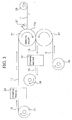
- FIG. 3 is a view schematically showing an
equipment configuration for manufacturing a plane coil
according to another embodiment of the present
invention along a manufacturing process.
-
-
Hereinafter, preferred embodiments of the present
invention will be described with reference to the
accompanying drawings.
-
FIG. 1 is a view schematically showing an
equipment configuration for manufacturing a plane coil
according to an embodiment of the present invention
along a manufacturing process, and Figs. 2A to 2G are
views showing the manufacturing process thereof.
-
First, FIG. 2A shows a planar configuration (on
the left) of a sheet member 10 used as a starting
material for manufacturing a plane coil according to
the embodiment and a cross-sectional view (on the
right) thereof taken along a line A-A' of the planar
configuration. The sheet member 10 used in this
embodiment basically has a three-layer structure in
which a conductive film 3 is stuck on a surface of an
insulative support sheet 1 with a pressure-sensitive
adhesive layer 2 interposed therebetween. For
example, a glassine paper is used as the insulative
support sheet 1, an acrylic pressure-sensitive
adhesive is used as the material of the pressure-sensitive
adhesive layer 2, and an aluminum (Al) foil
is used as the conductive film 3.
-
On a surface (a side to be brought into contact
with the pressure-sensitive adhesive layer 2) of the
glassine paper 1, a release agent (not shown) is in
advance coated by spraying or the like. This release
agent facilitates separation of the glassine paper 1
from the aluminum foil 3 in the process of
manufacturing the plane coil as described later.
Examples of the release agent for use include a higher
fatty acid and derivatives thereof, high melting point
wax, silicone oil, and polyvinyl alcohol. This
glassine paper (support sheet) 1 is peeled off during
the course of manufacturing the plane coil and becomes
unnecessary as described later. Accordingly, the
attribute of the support sheet is not necessarily
"insulative". A conductive support sheet can be used
instead of the glassine paper 1.
-
As the material of the pressure-sensitive
adhesive layer 2, other than the acrylic based
pressure-sensitive adhesive, epoxy-based, or
polyester-based, pressure-sensitive adhesive can be
used. Usual bonding adhesives may be used instead of
the pressure-sensitive adhesives. The pressure-sensitive
adhesives have lower heat resistance than
the usual bonding adhesives. However, the pressure-sensitive
adhesives have an advantage in that a curing
step is not required because the pressure-sensitive
adhesives have a property of adhering to a member to
be attached only by a slight pressure applied at room
temperature. Accordingly, it is desirable to
selectively use the pressure-sensitive adhesives or
the usual bonding adhesives depending on requirements.
For the conductive film 3, a copper foil, or a metal
foil made of an alloy such as Al or Cu, can be
suitably used other than the aluminum foil.
-
As described above, for the sheet member 10 used
as the starting material for manufacturing a plane
coil, a material with the three-layer structure is
used in this embodiment. In the material with the
three-layer structure, the glassine paper 1 on which
the release agent is coated and the aluminum foil 3
having a surface to which the pressure-bonded adhesive
layer 2 is attached, are stuck on each other with the
release agent and the pressure-bonded adhesive layer 2
interposed therebetween. As this sheet member 10, for
example, one commercially available as an "aluminum
tack seal material" can be suitably used. Note that
the thicknesses of the glassine paper 1, the pressure-sensitive
adhesive layer 2, and the aluminum foil 3,
are selected to be about 70 µm, 20 µm, and 30 µm,
respectively.
-
Next referring to FIG. 1, in the illustrated
equipment configuration, reference numeral 21 denotes
a winding body on which the sheet member 10 is wound
in a roll, and reference numeral 22 denotes a stamping
machine which stamps the sheet member 10, which is
being unwound and conveyed from the winding body 21 as
shown by arrows, in a required shape of coil.
Specifically, the stamping machine 22 stamps the sheet
member 10 in such a shape, as described later, that a
required coil portion, a frame portion defined around
the coil portion, and a joining portion connecting the
coil portion to the frame portion are left unstamped.
Although not shown, the stamping machine 22 includes a
support table where the sheet member 10 is loaded, a
die (punch) properly arranged so as to correspond to
the pattern shape including the required coil portion,
the frame portion, and the joining portion, and the
like.
-
Also, reference numeral 23 denotes a winding body
on which a protective sheet, which is made sticky, is
wound in a roll. In this embodiment, the protective
sheet includes a heat-resistant resin film 4 on one
surface of which a pressure-sensitive adhesive or a
bonding adhesive, which is less adhesive than that of
the pressure-sensitive adhesive layer 2 of the sheet
member 10, is coated (to form a pressure-sensitive
adhesive layer 5). Reference numeral 24 denotes a
guide roller which guides the protective sheet 4 (5),
which is being unwound and conveyed from the winding
body 23 as shown by arrows. Reference numerals 25 and
26 denote a pressure-bonding roller and a holding
roller, respectively, by which the protective sheet 4
(5) guided via the guide roller 24 is stuck onto a
surface of the sheet member (structure 11) stamped by
the stamping machine 22, the surface being on a side
where the aluminum foil is stuck. Reference numeral
27 denotes a separation roller by which the support
sheet (glassine paper) 1 is peeled off from the
structure 12 transmitted between the rollers 25 and
26. Reference numeral 28 denotes a guide roller which
guides the peeled-off glassine paper 1. Reference
numeral 29 denotes a winding roller which winds the
glassine paper 1 transmitted via the guide roller 28.
-
Also, reference numeral 30 denotes a winding body
on which the insulative support sheet (PET film 6 in
this embodiment) is wound in a roll. Reference
numeral 31 denotes a guide roller which guides the PET
film 6, which is being unwound and conveyed from the
winding body 30 as shown by arrows. Reference
numerals 32 and 33 denote a pressure-bonding roller
and a holding roller, respectively. The rollers 32
and 33 serve to stick a surface of the structure 13,
from which the glassine paper 1 is peeled off, onto a
surface of the PET film 6 opposite to the surface
where the protective sheet 4 (5) is stuck, the PET
film 6 being guided via the guide roller 31. Reference
numeral 34 denotes a separation roller by which the
protective sheet 4 (5) is peeled off from the
structure 14 transmitted between the rollers 32 and
33. Reference numeral 35 denotes a guide roller which
guides the peeled-off protective sheet 4 (5).
Reference numeral 36 denotes a winding roller which
winds the protective sheet 4 (5) transmitted via the
guide roller 35.
-
Also, reference numeral 37 denotes a stamping
machine which stamps the structure 15 at the joining
portion of the stamped aluminum foil (including the
pressure-sensitive adhesive layer) which is stuck on
the PET film 6 and a portion of the PET film 6
corresponding to the joining portion. Although not
shown, the stamping machine 37 includes a support
table where the structure 15 is loaded, a die (punch)
arranged so as to correspond to the shape of the
joining portion, and the like. Reference numeral 38
denotes a winding roller which winds a structure
stamped by the stamping machine 37, namely, a plane
coil 16 as a finally obtained product.
-
Hereinafter, a method of manufacturing the plane
coil 16 will be described with reference to FIGS. 2A
to 2G, showing the manufacturing steps thereof, and
the equipment configuration of FIG. 1. FIGs. 2B to 2G
show planar configurations (on the left) in the states
(the structures 11 to 16) after individual processing
steps for the starting material (the sheet member 10)
shown in FIG. 2A, and cross-sectional configurations
(on the right) taken along lines A-A' of the
respective planar configurations.
-
In the first step (FIG. 2B), the sheet member 10
(in which the aluminum foil 3 is stuck on the glassine
paper 1 with the pressure-sensitive adhesive layer 2
interposed therebetween), which is being unwound and
conveyed from the winding body 21, is stamped by the
stamping machine 22 into a shape such that a required
coil portion CP, frame portions FP1 and FP2, joining
portions LP1 and LP2 are left unstamped. Herein, the
frame portions FP1 and FP2 are defined around the coil
portion CP, and the joining portions LP1 and LP2
connects the coil portion CP to the frame portions FP1
and FP2, respectively. The joining portions LP1 and
LP2 also include portions connecting conductors, which
constitute the coil portion CP, inwardly and
outwardly. At this time, guide holes GH for
positioning, which are reference for stamping, are
formed in the frame portions FP1 on both sides of the
sheet 10 which are parallel to the conveying direction
thereof.
-
In the next step (FIG. 2C), the protective sheet
4 (5) guided from the winding body 23 via the guide
roller 24 is stuck by the pressure-bonding roller 25
and the holding roller 26 onto a surface of the
structure 11 stamped in the previous step where the
aluminum foil 3 (the coil portion CP, frame portions
FP1, FP2, and joining portions LP1, LP2) is stuck. In
other words, the shape of the coil portion CP is
transferred/laminated onto the protective sheet 4 (5).
-
In the next step (FIG. 2D), the glassine paper 1
is peeled off from the structure 12 conveyed between
the rollers 25 and 26 and wound to be recovered by the
separation roller 27, guide roller 28, and winding
roller 29. At this time, the glassine paper 1 can be
easily peeled off since the release agent is coated on
a surface (on the side that the pressure-sensitive
adhesive layer 2 is to be brought into contact) of the
glassine paper 1. On the other hand, the pressure-sensitive
adhesive layer 2 is left adhering to the
aluminum foil 3 (the coil portion CP, frame portions
FP1, FP2, and joining portions LP1, LP2) even if the
glassine paper 1 is separated.
-
In the next step (FIG. 2E), a surface (to which
the pressure-sensitive adhesive layer 2 is exposed) of
the structure 13, from which the glassine paper 1 is
peeled off in the previous step, the surface being
opposite to the surface where the protective sheet 4
(5) is stuck, is stuck by the pressure-bonding roller
32 and the holding roller 33 onto the PET film 6, the
PET film 6 being guided from the winding body 30 via
the guide roller 31. In other words, the coil portion
CP once held on the protective sheet 4 (5) is
transferred/laminated again onto the PET film 6.
-
In the next step (FIG. 2F), the protective sheet
4(5) is peeled off from the structure 14 transmitted
between the rollers 32 and 33 and wound to be
recovered by the separation roller 34, guide roller
35, and the winding roller 36. At this time, the
aluminum foil 3 (the coil portion CP, frame portions
FP1, FP2, and joining portions LP1, LP2) is left
adhering to the pressure-sensitive adhesive layer 2
even if the protective sheet 4 (5) is peeled off,
because the pressure-sensitive adhesive layer 5 of the
protective sheet is less adhesive than the pressure-sensitive
adhesive layer 2 of the sheet member. In
other words, the coil portion CP is held on the PET
film 6 with the pressure-sensitive adhesive layer 2
interposed therebetween without deforming.
-
In the last step (FIG. 2G), the structure 15,
from which the protective sheet 4 (5) is peeled off in
the previous step, is stamped by the stamping machine
37 at the joining portions LP1 and LP2 of the stamped
aluminum foil 3 (including the pressure-sensitive
adhesive layer 2), which is stuck on the PET film 6,
and at the portions of the PET film 6 corresponding to
the joining portions LP1 and LP2. In the example
shown in FIG. 2G, openings at the stamped portions of
the joining portions LP1 and LP2 are omitted. With
this stamping, the coil portion CP is cut off from the
frame portions FP1 and FP2 in the periphery thereof.
The structure 16 stamped by the stamping machine 37,
namely, the plane coil 16 as a product is then wound
by the winding roller 38.
-
As described above, according to the method of
manufacturing the plane coil 16 of this embodiment,
first, the sheet member 10 (in which the aluminum foil
3 is stuck on the glassine paper 1 with the pressure-sensitive
adhesive layer 2 interposed therebetween),
which is being unwound and conveyed from the winding
body 21, is stamped in a required shape of coil by the
stamping machine 22. Then, the protective sheet 4 (5)
is stuck onto the surface, where the aluminum foil 3
(the coil portion CP, frame portions FP1, FP2, and
joining portions LP1, LP2) is stuck, of the stamped
structure 11. Thus, the shape of coil is once held.
Further, the glassine paper 1 is peeled off from the
sheet member (the structure 12). The stamped aluminum
foil 3 is stuck onto the PET film 6 together with the
protective sheet 4 (5) holding the shape of coil, and
the protective sheet 4 (5) is then peeled off. Then,
the portions corresponding to the joining portions LP1
and LP2 in the aluminum foil 3 (including the
pressure-sensitive adhesive layer 2) are stamped out
by the stamping machine 37, thus obtaining the plane
coil 16.
-
According to the embodiment as described above,
the plane coil 16 is manufactured by using the
aluminum tack seal material, which is easily available
at comparatively low cost, as the sheet member 10, and
applying a stamping technique. Accordingly, it is
possible to achieve a reduction in the manufacturing
period, as well as a reduction in cost and a mass
production.
-
Furthermore, the stamped aluminum foil (the coil
portion CP) with no rigidity is once held by the
protective sheet 4 (5) to hold the shape thereof and
then stuck onto the PET film 6 which is a final
support base material. Accordingly, the coil with no
rigidity can be easily transferred/laminated onto the
PET film 6 while stably holding the shape, which
contributes to an improvement in the reliability of
the plane coil 16 as a product.
-
In the aforementioned embodiment, the stamped
aluminum foil (coil portion CP) with no rigidity is
once held by the protective sheet 4 (5) to hold the
shape and then transferred/laminated onto the PET film
6. In this case, the protective sheet 4 (5) becomes
unnecessary in the end. In view of the entire
materials used for manufacturing the plane coil,
partial waste will be produced. FIG. 3 exemplifies an
embodiment with such a disadvantage removed.
-
An equipment configuration according to the
embodiment shown in FIG. 3 differs from that according
to the aforementioned embodiment (FIG. 1) in the
following points: the configuration (the winding body
23, guide roller 24, pressure-bonding roller 25,
holding roller 26, separation roller 34, guide roller
35, and winding roller 36) related to supply,
sticking, separation, and recovery of the protective
sheet 4 (5) is not included; the pressure-bonding
roller 32 and the holding roller 33 for separating the
PET film 6 are not provided; an adhesive roller 41 (a
first roller which is made sticky) is provided; a
separation roller 27 (a second roller) is provided so
as to cooperate with the adhesive roller 41; and a
non-adhesive roller (a third roller) 42 for sticking
the PET film 6 is provided so as to cooperate with the
adhesive roller 41. The other components and
functions thereof are basically the same as those in
the case of the embodiment of FIG. 1, and thus the
description thereof is omitted.
-
Processings related to the manufacturing of the
plane coil 16 are basically the same as those
performed in the manufacturing process of FIGs. 2A to
2G, and thus the description thereof is omitted.
Note, in the embodiment shown in FIG. 3, the surface
of the structure 11 stamped by the stamping machine
22, on which the aluminum foil 3 is stuck, is stuck
onto the circumferential surface of the adhesive
roller 41 while the glassine paper 1 is peeled off
from the structure 11 by use of the separation roller
27. The structure 13a obtained after the glassine
paper 1 peeled off differs from the structure 13 shown
in FIG. 2D in that the protective sheet 4 (5) is not
stuck thereon. Furthermore, the PET film 6 is stuck
onto the structure 13a, which is being stuck onto the
circumferential surface of the adhesive roller 41 and
conveyed, by use of the non-adhesive roller 42.
-
In the present embodiment, a pressure-sensitive
adhesive or a bonding adhesive with a specific
adhesion is coated on the circumferential surface of
the adhesive roller 41 in order to smoothly and
continuously perform: the sticking of the stamped
structure 11 onto the adhesive roller 41; the
separation of the glassine paper 1; and the sticking
of the PET film 6 onto the structure 13a after the
separation. Specifically, a pressure-sensitive or
bonding adhesive including such an adhesion that
satisfies the relationship A<B<C is coated on the
circumferential surface of the adhesive roller 41
where A is adhesive strength of the pressure-sensitive
or bonding adhesive (pressure-sensitive adhesive layer
2) in the sheet member 10 to the glassine paper 1, B
is adhesive strength of the pressure-sensitive or
bonding adhesive coated on the circumferential surface
of the adhesive roller 41 to the aluminum foil 3, and
C is adhesive strength of the pressure-sensitive or
bonding adhesive (pressure-sensitive adhesive layer 2)
in the sheet member 10 to the PET film 6. As such a
pressure-sensitive or bonding adhesive, for example, a
silicone-based pressure-sensitive adhesive can be
used.
-
Also in the method of manufacturing the plane
coil 16 according to the embodiment shown in FIG. 3,
stamping technique is applied as is the case of the
manufacturing method according to the embodiment shown
in FIG. 1. Moreover, the shape of coil is held by
sticking the surface, where the aluminum foil 3 is
stuck, of the sheet member with no rigidity, which is
stamped in a required shape of coil, onto the
circumferential surface of the adhesive roller 41.
Accordingly, the manufacturing method according to the
embodiment shown in FIG. 3 has the like advantages
(reduction in cost, achievement of mass production,
and reduction in the manufacturing period) as the
manufacturing method according to the embodiment shown
in FIG. 1.
-
Furthermore, according to the present embodiment,
the protective sheet 4 (5), which is required in the
embodiment shown in FIG. 1, is unnecessary, and this
eliminates the need for sticking and peeling off the
protective sheet. Accordingly, the running cost can
be further reduced, and the manufacturing period can
be further shortened. In addition, mass productivity
can be further improved since the glassine paper 1 is
peeled off by the separation roller 27 while the
stamped sheet member is being held on the adhesive
roller 41.