EP1489656A2 - Method of fabrication of an unbreakable disc-shaped object and corresponding semiconductor circuit - Google Patents
Method of fabrication of an unbreakable disc-shaped object and corresponding semiconductor circuit Download PDFInfo
- Publication number
- EP1489656A2 EP1489656A2 EP04101941A EP04101941A EP1489656A2 EP 1489656 A2 EP1489656 A2 EP 1489656A2 EP 04101941 A EP04101941 A EP 04101941A EP 04101941 A EP04101941 A EP 04101941A EP 1489656 A2 EP1489656 A2 EP 1489656A2
- Authority
- EP
- European Patent Office
- Prior art keywords
- trench
- semiconductor
- mask
- substrate
- galvanizing
- Prior art date
- Legal status (The legal status is an assumption and is not a legal conclusion. Google has not performed a legal analysis and makes no representation as to the accuracy of the status listed.)
- Withdrawn
Links
Images


Classifications
-
- H—ELECTRICITY
- H01—ELECTRIC ELEMENTS
- H01L—SEMICONDUCTOR DEVICES NOT COVERED BY CLASS H10
- H01L23/00—Details of semiconductor or other solid state devices
- H01L23/562—Protection against mechanical damage
-
- C—CHEMISTRY; METALLURGY
- C25—ELECTROLYTIC OR ELECTROPHORETIC PROCESSES; APPARATUS THEREFOR
- C25D—PROCESSES FOR THE ELECTROLYTIC OR ELECTROPHORETIC PRODUCTION OF COATINGS; ELECTROFORMING; APPARATUS THEREFOR
- C25D5/00—Electroplating characterised by the process; Pretreatment or after-treatment of workpieces
- C25D5/02—Electroplating of selected surface areas
- C25D5/022—Electroplating of selected surface areas using masking means
-
- H—ELECTRICITY
- H01—ELECTRIC ELEMENTS
- H01L—SEMICONDUCTOR DEVICES NOT COVERED BY CLASS H10
- H01L23/00—Details of semiconductor or other solid state devices
- H01L23/58—Structural electrical arrangements for semiconductor devices not otherwise provided for, e.g. in combination with batteries
- H01L23/585—Structural electrical arrangements for semiconductor devices not otherwise provided for, e.g. in combination with batteries comprising conductive layers or plates or strips or rods or rings
-
- H—ELECTRICITY
- H01—ELECTRIC ELEMENTS
- H01L—SEMICONDUCTOR DEVICES NOT COVERED BY CLASS H10
- H01L2924/00—Indexing scheme for arrangements or methods for connecting or disconnecting semiconductor or solid-state bodies as covered by H01L24/00
- H01L2924/0001—Technical content checked by a classifier
- H01L2924/0002—Not covered by any one of groups H01L24/00, H01L24/00 and H01L2224/00
Definitions
- the present invention relates to a method for Production of an unbreakable, disc-shaped object and an associated semiconductor circuit arrangement and in particular to a method for "seed-layer" -free galvanic Manufacture of an ultra-thin break-proof semiconductor wafer, like he did in the manufacture of semiconductor integrated circuits is used.
- ultra-thin semiconductor wafers can, for example are manufactured using conventional semiconductor wafers, which have an initial thickness of about 500 to 1000 microns and after the production of respective switching elements or Semiconductor components to a corresponding final thickness be thinly ground.
- Figure 1 shows a simplified side view of a disc-shaped Item such as a semiconductor wafer 1 with a standard thickness of approx. 500 to 1000 ⁇ m, for example is parked in a horde. Under a horde is usually understood as a magazine for semiconductor wafers, in which up to 25 pieces can be stored upright.
- FIG. 2 shows a simplified side view when a thin wafer 1A is deposited in a corresponding tray or a magazine for semiconductor wafers. Since such a thin wafer is fundamentally bent due to its thin substrate thickness of less than 200 ⁇ m and an asymmetrical layer structure, the support reaction F H splits vectorially into a so-called normal component F N and a shear force component F Q according to FIG. Again, the support reaction F H is at least as large as the weight G of the thin wafer or ultra-thin semiconductor wafer 1A.
- FIGS. 3A to 3D To illustrate the forces acting on and in the thin wafer 1A, the cutting forces F M , the transverse forces F Q and the shear stresses ⁇ as a function of a distance x for the simplified case of a beam clamped on one side are shown in FIGS. 3A to 3D.
- the cutting forces F M in the carrier or in the carrier material are therefore maximal at the clamping point zero and minimal at the loading point x, wherein they run linearly in between.
- the transverse forces F Q are shown as a function of the location, with a constant transverse force F Q being obtained from the clamping point zero to the loading point x for this example.
- the cutting forces F M act as a torque, which, however, does not represent a risk of breakage, since it only causes tensile and compressive stresses which the semiconductor wafer and in particular silicon can withstand with ease.
- the lateral force F Q shown in FIG. 3C causes the shear stresses ⁇ shown in FIG. 3D, which have their maximum value in the middle of a cross section, not shown. If the beam shown in FIG. 3A has the same cross section everywhere, the shear stresses ⁇ are constant for a clamping point zero up to a loading point x. However, this does not apply to a disk-shaped object such as a semiconductor wafer.
- the external load also due to stress or the stress of an oxide layer replaced on a front side of a semiconductor wafer.
- stresses ⁇ especially after the external one
- the application of force through a support reaction when placing a semiconductor wafer in a horde or sucking a bent thin wafer on a vacuum chuck For example, the application of force through a support reaction when placing a semiconductor wafer in a horde or sucking a bent thin wafer on a vacuum chuck.
- Figure 4 shows a partial top view of such a disc-shaped Object, such as that of an ultra-thin Semiconductor wafer 1A is known.
- the ultra-thin semiconductor wafer 1A which has a multiplicity of integrated semiconductor circuits 3 or chips with a saw or scribe frame 4 in between, is deposited over its peripheral edge 2 on a support point AP, for example in a tray.
- a sawing or scoring frame 4 is understood below to mean the distance between two semiconductor circuits 3, which is usually required for separating or sawing.
- the support reactions F H described above are accordingly generated at this support point AP, which also results in the undesirable shear stresses ⁇ .
- monocrystalline silicon as is usually used for semiconductor wafers, can withstand almost no shear stresses ⁇ , a hairline crack 5 now arises in the region of the contact point AP according to FIG.
- Figure 5 shows a simplified perspective view of this 4 according to the same reference numerals or designate corresponding elements and repeat them Description is waived below.
- a shear stress ⁇ öz is accordingly generated at the contact point AP. More precisely, consequently, a force acts on the surface after the infinitesimal surface in the z direction.
- the material of the disk-shaped object and in particular monocrystalline silicon semiconductor material cannot withstand these shear stresses ⁇ and therefore suddenly changes its spatial coordinates from one side of the hairline crack 5 to the other side.
- Hairline cracks 5 of this type propagate very easily, in particular in ultra-thin semiconductor wafers 1A, which is why they represent an essential cause for the extremely high risk of breakage in such ultra-thin semiconductor wafers.
- carrier wafers used with an ultra-thin product wafer on a carrier wafers of normal thickness with high or medium temperature resistance Connecting materials is connected.
- a disadvantage of one such carrier technology are the additional investments as well as high manufacturing costs.
- the invention is therefore based on the object of a method for the manufacture of a break-resistant disc-shaped object and an associated semiconductor circuit arrangement to create, the fragility in particular of ultra-thin disc-shaped objects significantly reduced is.
- the formation of a galvanizing mask with exposed areas on the front of the support substrate and performing electroplating for filling up the exposed areas of the galvanizing mask can for the fragility of ultra thin Shear stresses responsible for semiconductor wafers can be caught very effectively, making a wafer break essential is reduced.
- the filling of the trenches and the formation are preferred performed the plating mask simultaneously, whereby for example, a photosensitive varnish as a shear stress resistant Material spun all over and into the trenches introduced and photolithographically to form the galvanizing mask is structured. That way it can Filling the trenches with shear-resistant material and the formation of the galvanizing mask is realized very inexpensively become.
- a photosensitive varnish is preferred Photoimide used.
- a metallic material can also be used shear-proof material in the trenches galvanically filled become, which increases resistance to shear stress further improved.
- a preferably takes place very uniform contacting of the carrier substrate from it Back, in particular a vacuum chuck with a Variety of contact tips and intermediate vacuum channels be used for uniform contacting can.
- a vacuum chuck with a Variety of contact tips and intermediate vacuum channels be used for uniform contacting can.
- a sufficient attack power with which a natural oxide on the semiconductor wafer and / or the contact tips is destroyed and a necessary for the galvanization uniform contacting is made possible.
- seed layer -free metal layers are formed, the galvanizing mask being common with the galvanic filling layer a particularly high resistance has shear stresses.
- an electrically conductive auxiliary structure for galvanization from isolated exposed areas of the plating mask be formed with an insulating layer are covered and therefore not directly galvanized can be.
- isolated exposed areas are, for example, gate connection areas.
- a conductor track structure is preferably used as the auxiliary structure used by a substrate area in the saw frame leads to the isolated exposed areas and thus Galvanization also enables isolated areas.
- At least one trench on a block edge in the substrate trained and with a shear resistant material filled up, as well as a galvanizing mask on the surface of the semiconductor substrate with a plurality of exposed Formed areas, with a galvanic filler layer are preferred.
- the semiconductor circuit arrangement preferably has one Variety of power transistors on their gate layers can be connected via a gate connection area.
- FIG. 6A shows a simplified partial sectional view of a Break-proof semiconductor wafers or carrier substrates 1 in front of one Thin, with the same or corresponding layers as in the Figures 1 to 5 designate and repeat description is subsequently waived.
- the electrically conductive carrier substrate 1 consists, for example, of a semiconductor wafer and in particular of a silicon semiconductor wafer of a first conductivity type n - with a conventional initial thickness D A of approximately 500 to 1000 ⁇ m.
- the first step is according to FIG. 6A at least in the area of the saw frame or scoring frame 4 a trench G1 with a small first trench depth h1 for example 5 to 50 ⁇ m and / or at least one trench G2 with a second trench depth h2 of, for example, 50 to 200 ⁇ m on the front of the electrically conductive carrier substrate or semiconductor wafers 1 formed.
- the saw frame 4 according to FIGS. 4 and 5 is essentially one Has lattice-shaped structure and the individual integrated Circuits 3 are spaced apart also the trenches G1 formed in the area of the saw frame 4 or G2 essentially a lattice-like structure.
- Training the essentially matrix-shaped, i.e. in lines and columns formed trenches G1 and G2 can for example by means of plasma etching, wet chemical etching in a potassium hydroxide solution, light-induced etching, anodic silicon etching, Laser cutting and / or mechanical sawing can be performed.
- a trench depth h1 or h2 of the trenches G1 or G2 is preferably greater than an end thickness D E1 or D E2 of a thinned or ultra-thin semiconductor wafer 1A shown in FIG. 6C.
- the first trench depth h1 is therefore approximately 5 to 50 ⁇ m, in particular low-voltage components such as, for example, low-voltage power transistors, or the second trench depth h2 is approximately 50 to 200 ⁇ m, preferably high-voltage Components such as high-voltage power transistors can be realized.
- a trench width is dependent on one used Filling material dimensioned so that later Filling material to be introduced into the trenches as simply as possible G1 or G2 can be introduced. They preferably have Trenches G1 and G2 a trench width of 5 to 100 microns and can consequently easily positioned within the saw frame 4 become.
- A is preferably used here Duroplast applied in the area of the saw frame 4 and then cross-linked or hardened, making a medium-temperature resistant Material to compensate for the aforementioned Receives shear stresses.
- a shear stress-resistant material SF preferably a photosensitive varnish over the entire surface centrifuged, first about 10 to 50 microns thick Receives photoresist layer.
- the photoresist layer is here not only introduced into the trenches G1 and G2, but serves also the formation of a galvanizing mask 6. More precisely is said here after the photosensitive has been spun on Lacquers (preferably photo imide) and simultaneous filling the trenches G1 and G2 then a photolithographic Structuring carried out, preferably in the areas of the scoring frame 4 or the trenches G1 or G2 an exposure and the photoresist is then removed from the cell field ZF can be removed or stripped.
- Lacquers preferably photo imide
- Photoimide used in a variety of standard processes and is temperature-resistant up to approx. 400 ° C, it is as shear stress resistant material SF for process steps in in a subsequent medium temperature range.
- the trenches G1 and G2 can be used simultaneously with a shear-resistant material SF filled as well Electroplating mask 6 on the front side of the semiconductor wafer 1 can be trained, making one very effective Processing receives.
- electroplating is therefore carried out to fill up the exposed areas of the electroplating mask 6, in particular a uniform contacting of the carrier substrate or semiconductor wafer 1 from its rear side.
- a further grinding of the semiconductor wafer 1 can optionally be carried out to reduce fluctuations in the initial thickness D A , which is necessary in particular for ultra-thin semiconductor wafers in a thickness range from 5 to 50 ⁇ m.
- a semiconductor substrate has a specific resistance of 60 ohm x cm, that is to say the basic material for 1200 volt-blocking semiconductor components. Since the semiconductor wafer is usually approximately 500 ⁇ m or 0.5 mm thick, the semiconductor series resistance 15 or R HL is therefore approximately 3 ohms.
- the series electrolyte resistance 16 or R EL of an electrolyte required for electroplating with a typical conductivity of 100 mSiemens is 0.1 ohms at an electrode distance of approximately one centimeter from the wafer surface, that is significantly less than the resistance R HL in the semiconductor.
- the voltage drop across the double layer at which the electrochemical reaction for depositing a solderable metal, preferably copper or nickel, takes place is of the order of magnitude of 0.5 volt. This voltage must therefore be compared with the voltage drops across the semiconductor substrate 1 and the electrolytes in order to be able to assess whether there is a chance of a uniform process.
- a typical current density in electroplating is approx. 1 - 10 mA / cm 2 . Inserted into Ohm's law, this results in a voltage drop of 0.1 mV in the electrolyte and 3 mV in the semiconductor substrate, i.e. significantly less than the electrochemical overvoltage at the location of the deposition reaction. This results in the prerequisite for the success of the electroplating process according to the invention. On the other hand, if you only contacted the semiconductor wafer somewhere along the edge, it can easily be calculated that series resistances of up to several k ⁇ would have to be expected, which would destroy any chance of uniformity.
- this required, uniform contacting takes place of the semiconductor wafer 1 by a device that from an uneven contact plate with many tips exists, with their sufficient attack power, for example by means of a vacuum chuck with a suitable seal is achieved at the wafer edge.
- the attack power must be here be so high that a natural oxide on the carrier substrate or the contact tips 13 is destroyed and the direct contact to the semiconductor material is guaranteed. There this cannot be achieved in the flat surface
- the vacuum chuck represents the cathode K and is via a voltage supply 17 electrically with the anode or the electrolyte connected.
- Vacuum channels 14 To realize a corresponding negative pressure via the Vacuum channels 14 is a (not shown, but necessary) seal provided.
- the disk-shaped object or semiconductor substrate 1 is finally thinned from its rear side to a final thickness D E1 or D E2 for realizing a thinned carrier substrate or ultra-thin semiconductor wafer 1A, the respective final thicknesses D E1 or D E2 being smaller are the trench depths h1 and h2 of the trenches G1 and G2 formed.
- Mechanical grinding with subsequent spin etching and final polishing is preferably carried out here, since the wet chemical process does not allow the required thickness fluctuations in the uniformity to be achieved.
- a rear-side metallization 18 is formed, which represents a drain connection, for example.
- FIGS. 7A to 7C show simplified partial sectional views to illustrate an alternative manufacturing step especially for filling the trenches with a shear stress resistant Material, the same reference numerals being the same or designate corresponding layers or elements as in Figures 1 to 6 and a repeated description is subsequently waived.
- a Oxide hard mask HM not only formed or etched the trenches G. be, but in a step according to Figure 7B Using the electroplating process described above and the hard mask HM as a protective layer also with a metallic material as shear-resistant material SF be replenished.
- Such electroplated metals SF are particularly resistant to this Shear stresses, which is why the spread of hairline cracks in particularly thin semiconductor wafers (i.e. less than 50 ⁇ m) can be prevented particularly reliably.
- cavities or so-called Voids V which with such a galvanic Deposition formed in the trenches or in the filling material SF avoid a layout can serve according to Figure 7D.
- V in the trenches can be avoided to avoid voids G the saw frame 4 the layout, for example in the form of a Jagged ZR are executed, which has the consequence that electroplating specifically before the metal grows together finished in the wider areas of the zigzag edge ZR then the proportion of Voids V is small compared to that Proportion of the trench thickness where the metal SF has grown together properly is.
- the Voids V with straight edges may be from purely random, microscopic fluctuations in the Trench width depends on it and therefore its extent cannot be controlled are.
- the thinned semiconductor wafer 1A again has a final thickness, which is smaller than the depth of the trench G, the structures protruding on the back as alignment marks JM used for a particularly easy front-back adjustment can be.
- shear-resistant material SF which is formed galvanically in the trench G can preferably Copper (Cu) can be used.
- Tungsten the metal with the most favorable properties, which is electroplated in the trenches G.
- Figure 8 shows a simplified partial top view of an ultra thin break-resistant semiconductor wafers according to a third exemplary embodiment, the same reference numerals being the same or designate corresponding elements or layers such as in Figures 1 to 7 and a repeated description is subsequently waived.
- a saw frame 4 has two from each other spaced trenches G, which with one of the above described methods are formed or filled can.
- Those separated from each other by the saw frame 4 Semiconductor components usually have a cell field ZF with active components, but also so-called connection surfaces GP, which is usually formed on insulating layers 8 are and therefore not at least not immediately can be galvanized.
- connection surfaces GP which is usually formed on insulating layers 8 are and therefore not at least not immediately can be galvanized.
- connection surfaces GP which is usually formed on insulating layers 8 are and therefore not at least not immediately can be galvanized.
- Conductor structures can preferably be used for this be that directly on the substrate surface or the surface of the
- Figure 9 shows a simplified partial sectional view along a section A-A according to Figure 8, with the same reference numerals same or corresponding layers as in Figures 1 to 8 and a repeated description below is waived.
- FIG. 9 is used to fill up the exposed, however area GP insulated by the insulating layer 8 for the gate connection areas an auxiliary structure HF on the surface of the semiconductor wafer 1 and at least on the surface of the Insulating layer 8 in the exposed insulated area GP to to a substrate area 19 in the saw frame 4, for example formed and structured via a trench G, whereby one a contact from the substrate area 19 to the isolated exposed area GP receives.
- the isolated exposed area is galvanically filled, which not only reduces shear stress material but also, for example, a so-called gate connection area or gate pad GP by means of those described above Electroplating process can be formed.
- the lines RS indicate the edges of the sawing track in the saw frame 4, whereby the gate connection areas GP from electrically conductive carrier substrate are separated.
- Figure 10 shows a simplified partial sectional view of a Cell field ZF according to a fourth embodiment, wherein same reference numerals same or corresponding layers or designate elements as in FIGS. 1 to 9 and a repeated description is omitted below becomes.
- local p-wells 9A are formed in an n - semiconductor substrate 1 as so-called p-bodies, into which source regions S are introduced on the surface.
- p-bodies On the surface of the semiconductor substrate 1 there is a gate insulation layer (not shown), a gate layer GS and an insulation layer 8, which are structured into cell stacks, in the usual way.
- Contact holes KL are also formed between each cell stack with a dimension L in the semiconductor substrate 1 or the p-wells 9A and through the source regions S, as a result of which the galvanization described above can be carried out.
- the galvanic filling layer 11A up to a line or a level N1, where you first of all receives separate plating plugs or mushrooms.
- these mushrooms 11A together, creating a galvanic Fill layer 11B, for example at a line or level N2 receives.
- the galvanization method according to the invention is in particular applicable when the cell grid L of the power transistors is much smaller than a height H of the galvanizing mask or bumps 6.
- the present invention by forming Trenches and filling these trenches with shear stress resistant Material disk-shaped objects and in particular semiconductor wafers made unbreakable. So these items or semiconductor wafers but still manageable after thinning remain, the disc-shaped objects or Semiconductor wafers through galvanization masks and in between lying galvanic filling layers further stabilized, whereby highly break-proof semiconductor wafers and associated semiconductor circuit arrangements receives.
- the invention has been described above using a silicon semiconductor wafer described. However, it is not limited to this and also includes other semiconductor materials in the same way. In the same way can be used as shear stress resistant Materials other than photoimide or Copper can be used to reduce similar properties or prevention of the shear stresses mentioned at the beginning exhibit.
Abstract
Description
Die vorliegende Erfindung bezieht sich auf ein Verfahren zur Herstellung eines bruchfesten scheibenförmigen Gegenstands sowie einer zugehörigen Halbleiterschaltungsanordnung und insbesondere auf ein Verfahren zur "seed-layer"-freien galvanischen Herstellung eines ultradünnen bruchfesten Halbleiterwafers, wie er bei der Herstellung von integrierten Halbleiterschaltungen verwendet wird.The present invention relates to a method for Production of an unbreakable, disc-shaped object and an associated semiconductor circuit arrangement and in particular to a method for "seed-layer" -free galvanic Manufacture of an ultra-thin break-proof semiconductor wafer, like he did in the manufacture of semiconductor integrated circuits is used.
Für eine Vielzahl von gegenwärtigen und zukünftigen Anwendungen von elektronischen Bauelementen und insbesondere von integrierten Schaltungen (IC) ist es vorteilhaft, die Gesamtdicke dieser integrierten Schaltungen bzw. Halbleiterschaltungen auf wenige Mikrometer zu beschränken. Derart dünne Halbleiterschaltungen bzw. Chips haben eine sehr geringe Masse und eine sehr geringe Bauhöhe, weshalb sie für eine Vielzahl von Anwendungsfeldern beispielsweise in zukünftiger Wegwerf-Elektronik sowie für Chipkarten und Smartcards von Bedeutung sind.For a variety of current and future applications of electronic components and in particular of integrated Circuits (IC) it is advantageous to the total thickness these integrated circuits or semiconductor circuits to be limited to a few micrometers. Such thin semiconductor circuits or chips have a very low mass and a very low profile, which is why they are suitable for a variety of fields of application, for example in future disposable electronics as well as for smart cards and smart cards are.
Derartige ultradünne Halbleiterwafer können beispielsweise anhand von herkömmlichen Halbleiterwafern hergestellt werden, die eine Anfangsdicke von ca. 500 bis 1000 µm aufweisen und nach der Herstellung von jeweiligen Schaltelementen bzw. Halbleiterbauelementen bis auf eine entsprechende Enddicke dünngeschliffen werden.Such ultra-thin semiconductor wafers can, for example are manufactured using conventional semiconductor wafers, which have an initial thickness of about 500 to 1000 microns and after the production of respective switching elements or Semiconductor components to a corresponding final thickness be thinly ground.
Da jedoch für zukünftige Halbleiterbauelemente Dicken von deutlich weniger als 200 µm erwünscht sind, wobei ferner insbesondere eine beidseitige Strukturierung zur Ausbildung von beidseitig strukturierten Halbleiterbauelementen gefordert ist, besteht ein wesentliches Problem bei der Herstellung von ultradünnen Halbleiterschaltungen in der Vermeidung eines Bruches von Dünnwafern bzw. ultradünnen Halbleiterwafern.However, since thicknesses of significantly less than 200 microns are desired, furthermore in particular a bilateral structuring for the formation of semiconductor components structured on both sides is a major problem in the manufacture of ultra-thin semiconductor circuits in avoiding a Fracture of thin wafers or ultra-thin semiconductor wafers.
Zum besseren Verständnis wird zunächst die Ursache der hohen Bruchgefahr von ultradünnen Halbleiterwafern im einzelnen beschrieben.To better understand the cause of the high Risk of breakage of ultra-thin semiconductor wafers described in detail.
Figur 1 zeigt eine vereinfachte Seitenansicht eines scheibenförmigen Gegenstands wie z.B. eines Halbleiterwafers 1 mit einer Standarddicke von ca. 500 bis 1000 µm, wenn er beispielsweise in einer Horde abgestellt wird. Unter einer Horde versteht man üblicherweise ein Magazin für Halbleiterwafer, in dem bis zu 25 Stück stehend aufbewahrt werden können.Figure 1 shows a simplified side view of a disc-shaped Item such as a semiconductor wafer 1 with a standard thickness of approx. 500 to 1000 µm, for example is parked in a horde. Under a horde is usually understood as a magazine for semiconductor wafers, in which up to 25 pieces can be stored upright.
Beim Ablegen eines derartigen herkömmlichen Halbleiterwafers 1 erfährt dieser an einem Auflagepunkt eine sogenannte Auflagerreaktion FH, die zumindest seinem Eigengewicht G entspricht. Diese Auflagerreaktion FH bewirkt in erster Näherung Druckkräfte, die parallel zur Waferoberfläche wirken. Sogenannte Schubspannungen treten bei derartigen dicken Halbleiterwafern 1 üblicherweise nicht auf.When such a conventional semiconductor wafer 1 is deposited, it experiences a so-called support reaction F H at a support point, which corresponds at least to its own weight G. In a first approximation, this support reaction F H causes pressure forces that act parallel to the wafer surface. So-called shear stresses usually do not occur in such thick semiconductor wafers 1.
Demgegenüber zeigt Figur 2 eine vereinfachte Seitenansicht
bei der Ablage eines Dünnwafers 1A in einer entsprechenden
Horde bzw. einem Magazin für Halbleiterwafer. Da ein derartiger
Dünnwafer auf Grund seiner dünnen Substratdicke kleiner
200 µm und eines asymmetrischen Schichtaufbaus grundsätzlich
verbogen ist, spaltet sich gemäß Figur 2 die Auflagerreaktion
FH in eine sogenannte Normalkomponente FN und eine Querkraftkomponente
FQ vektoriell auf. Wiederum ist die Auflagerreaktion
FH mindestens so groß wie das Gewicht G des Dünnwafers
bzw. ultradünnen Halbleiterwafers 1A.In contrast, FIG. 2 shows a simplified side view when a
Zur Veranschaulichung der auf den und im Dünnwafer 1A wirkenden
Kräfte sind in den Figuren 3A bis 3D die Schnittkräfte
FM, die Querkräfte FQ, sowie die Schubspannungen τ in Abhängigkeit
von einer Entfernung x für den vereinfachten Fall eines
einseitig eingespannten Trägers dargestellt.To illustrate the forces acting on and in the
Figur 3A zeigt eine vereinfachte Darstellung eines derartigen bei x=0 eingespannten Trägers, wobei in einer Entfernung x eine Belastung F=FQ wirkt. Gemäß Figur 3B sind demzufolge im Träger bzw. im Trägermaterial die Schnittkräfte FM im Einspannpunkt Null maximal und im Belastungspunkt x minimal, wobei sie dazwischen linear verlaufen. Gemäß Figur 3C sind die Querkräfte FQ in Abhängigkeit vom Ort dargestellt, wobei man für dieses Beispiel eine konstante Querkraft FQ vom Einspannpunkt Null bis zum Belastungspunkt x erhält. Die Schnittkräfte FM wirken hierbei als Drehmoment, welches jedoch keine Bruchgefahr darstellt, da es nur Zug- und Druckspannungen hervorruft, denen der Halbleiterwafer und insbesondere Silizium mühelos standhält.FIG. 3A shows a simplified illustration of such a beam clamped in at x = 0, a load F = F Q acting at a distance x. According to FIG. 3B, the cutting forces F M in the carrier or in the carrier material are therefore maximal at the clamping point zero and minimal at the loading point x, wherein they run linearly in between. According to FIG. 3C, the transverse forces F Q are shown as a function of the location, with a constant transverse force F Q being obtained from the clamping point zero to the loading point x for this example. The cutting forces F M act as a torque, which, however, does not represent a risk of breakage, since it only causes tensile and compressive stresses which the semiconductor wafer and in particular silicon can withstand with ease.
Die in Figur 3C dargestellte Querkraft FQ ruft jedoch im Material die in Figur 3D dargestellten Schubspannungen τ hervor, die in der Mitte eines nicht dargestellten Querschnitts ihren Maximalwert aufweisen. Wenn der in Figur 3A dargestellte Träger überall den selben Querschnitt aufweist, sind die Schubspannungen τ konstant für einen Einspannpunkt Null bis zu einem Belastungspunkt x. Dies gilt jedoch nicht für einen scheibenförmigen Gegenstand wie beispielsweise einen Halbleiterwafer.The lateral force F Q shown in FIG. 3C, however, causes the shear stresses τ shown in FIG. 3D, which have their maximum value in the middle of a cross section, not shown. If the beam shown in FIG. 3A has the same cross section everywhere, the shear stresses τ are constant for a clamping point zero up to a loading point x. However, this does not apply to a disk-shaped object such as a semiconductor wafer.
Insbesondere bei Halbleiterwafern wird die äußere Belastung auch durch eine Beanspruchung bzw. den Stress einer Oxidschicht an einer Vorderseite eines Halbleiterwafers ersetzt. Demzufolge gibt es auch Spannungen τ, besonders nach der äußeren Krafteinwirkung durch eine Auflagerreaktion beispielsweise beim Ablegen eines Halbleiterwafers in einer Horde oder dem Ansaugen eines verbogenen Dünnwafers auf einem Vakuumchuck. In the case of semiconductor wafers in particular, the external load also due to stress or the stress of an oxide layer replaced on a front side of a semiconductor wafer. As a result, there are also stresses τ, especially after the external one For example, the application of force through a support reaction when placing a semiconductor wafer in a horde or sucking a bent thin wafer on a vacuum chuck.
Figur 4 zeigt eine Teil-Draufsicht eines derartigen scheibenförmigen
Gegenstandes, wie er beispielsweise als ultradünner
Halbleiterwafer 1A bekannt ist.Figure 4 shows a partial top view of such a disc-shaped
Object, such as that of an
Gemäß Figur 4 wird der ultradünne Halbleiterwafer 1A, der eine
Vielzahl von integrierten Halbleiterschaltungen 3 bzw.
Chips mit dazwischen liegenden Säge- bzw. Ritzrahmen 4 aufweist,
über seinen Umfangsrand 2 auf einen Auflagepunkt AP
beispielsweise in einer Horde abgelegt. Unter einem Säge-
bzw. Ritzrahmen 4 wird nachfolgend der Abstand zwischen zwei
Halbleiterschaltungen 3 verstanden, der üblicherweise zum
Vereinzeln bzw. Sägen benötigt wird. An diesem Auflagepunkt
AP werden demzufolge die vorstehend beschriebenen Auflagerreaktionen
FH erzeugt, woraus auch die unerwünschten Schubspannungen
τ resultieren. Da jedoch insbesondere monokristallines
Silizium, wie es üblicherweise für Halbleiterwafer verwendet
wird, nahezu keine Schubspannungen τ aushält, entsteht nun
gemäß Figur 4 ein Haarriss 5 im Bereich des Auflagepunktes
AP.According to FIG. 4, the
Figur 5 zeigt eine vereinfachte perspektivische Ansicht dieses Vorgangs gemäß Figur 4, wobei gleiche Bezugszeichen gleiche oder entsprechende Elemente bezeichnen und auf eine wiederholte Beschreibung nachfolgend verzichtet wird.Figure 5 shows a simplified perspective view of this 4 according to the same reference numerals or designate corresponding elements and repeat them Description is waived below.
Gemäß Figur 5 wird demzufolge am Auflagepunkt AP eine Schubspannung
τöz erzeugt. Genauer gesagt greift demzufolge eine
Kraft an der nach Ö infinitesimalen Fläche in z-Richtung an.
Das Material des scheibenförmigen Gegenstandes und insbesondere
monokristallines Silizium-Halbleitermaterial kann diesen
Schubspannungen τ jedoch nicht widerstehen und verändert daher
sprungartig seine Ortskoordinaten von der eine Seite des
Haarrisses 5 zu der anderen Seite. Derartige Haarrisse 5
pflanzen sich sehr leicht insbesondere in ultradünnen Halbleiterwafern
1A fort, weshalb sie eine wesentliche Ursache
für die außerordentlich hohe Bruchgefahr bei derartigen ultradünnen
Halbleiterwafern darstellen. According to FIG. 5, a shear stress τ öz is accordingly generated at the contact point AP. More precisely, consequently, a force acts on the surface after the infinitesimal surface in the z direction. However, the material of the disk-shaped object and in particular monocrystalline silicon semiconductor material cannot withstand these shear stresses τ and therefore suddenly changes its spatial coordinates from one side of the
Zur Vermeidung einer derartigen Zerbrechlichkeit von ultradünnen Halbleiterwafern wurden entweder speziell adaptierte Transportvorrichtungen und sogenannte Chucks in den Bearbeitungsmaschinen mit beispielsweise speziellen Transporthorden zur Verfügung gestellt, wobei ein Waferbruch nur reduziert, jedoch nicht ausgeschlossen werden kann. Insbesondere mit der Zunahme eines Durchmessers von Halbleiterwafern von 150 mm auf über 300 mm können derartige Probleme jedoch nicht vollständig beseitigt werden.To avoid such fragility of ultra thin Semiconductor wafers were either specially adapted Transport devices and so-called chucks in the processing machines with, for example, special transport trays provided, whereby a wafer break only reduces however cannot be excluded. Especially with the Increase in diameter of semiconductor wafers by 150 mm Such problems cannot be completely over 300 mm be eliminated.
Gemäß einer alternativen Lösungsmöglichkeit werden Trägerwafer verwendet, wobei ein ultradünner Produktwafer auf einem normal dicken Trägerwafer mit hoch- oder mitteltemperaturfesten Verbindungsmaterialien verbunden wird. Nachteilig bei einer derartigen Trägertechnik sind jedoch die zusätzlichen Investitionen sowie hohen Herstellungskosten.According to an alternative solution, carrier wafers used, with an ultra-thin product wafer on a carrier wafers of normal thickness with high or medium temperature resistance Connecting materials is connected. A disadvantage of one such carrier technology, however, are the additional investments as well as high manufacturing costs.
Ein weiterer Ansatz, die Zerbrechlichkeit insbesondere von ultradünnen Halbleiterwafern zu vermindern, ist beispielsweise das Nachbearbeiten der Kante bzw. des Umfangsrandes mit einem kombinierten Wasserstrahl-Laserschneidegerät. Der Waferbruch lässt sich jedoch nur um einen bestimmten Prozentsatz verringern.Another approach, the fragility in particular of To reduce ultra-thin semiconductor wafers, for example the finishing of the edge or the peripheral edge with a combined water jet laser cutter. The wafer break however, can only be by a certain percentage reduce.
Der Erfindung liegt daher die Aufgabe zu Grunde, ein Verfahren zur Herstellung eines bruchfesten scheibenförmigen Gegenstandes sowie eine zugehörige Halbleiterschaltungsanordnung zu schaffen, wobei die Zerbrechlichkeit insbesondere von ultradünnen scheibenförmigen Gegenständen wesentlich verringert ist.The invention is therefore based on the object of a method for the manufacture of a break-resistant disc-shaped object and an associated semiconductor circuit arrangement to create, the fragility in particular of ultra-thin disc-shaped objects significantly reduced is.
Erfindungsgemäß wird diese Aufgabe hinsichtlich des Verfahrens durch die Maßnahmen des Patentanspruchs 1 und hinsichtlich der Halbleiterschaltungsanordnung durch die Merkmale des Patentanspruchs 17 gelöst. According to the invention, this object is achieved with regard to the method by the measures of claim 1 and with regard the semiconductor circuit arrangement by the features of Claim 17 solved.
Insbesondere durch das Ausbilden von zumindest einem Graben im Bereich des Sägerahmens, dem Auffüllen des Grabens mit einem schubspannungsfesten Material, dem Ausbilden einer Galvanisierungsmaske mit frei liegenden Bereichen an der Vorderseite des Trägersubstrats und dem Durchführen einer Galvanisierung zum Auffüllen der frei liegenden Bereiche der Galvanisierungsmaske können die für die Zerbrechlichkeit von ultradünnen Halbleiterwafern verantwortlichen Schubspannungen sehr effektiv aufgefangen werden, wodurch ein Waferbruch wesentlich verringert ist. Hierbei ermöglicht eine in den freiliegenden Bereichen der Galvanisierungsmaske ausgebildete galvanische Füllschicht erstmalig auch ein Dünnen des scheibenförmigen Gegenstands auf Enddicken unterhalb von 10 µm.In particular by forming at least one trench in the area of the saw frame, filling the trench with a shear-resistant material, the formation of a galvanizing mask with exposed areas on the front of the support substrate and performing electroplating for filling up the exposed areas of the galvanizing mask can for the fragility of ultra thin Shear stresses responsible for semiconductor wafers can be caught very effectively, making a wafer break essential is reduced. This allows one in the exposed Areas of the galvanizing mask galvanic filling layer for the first time also thinning the disc-shaped Object to a final thickness below 10 µm.
Vorzugsweise wird das Auffüllen der Gräben sowie das Ausbilden der Galvanisierungsmaske gleichzeitig durchgeführt, wobei beispielsweise ein fotosensitiver Lack als schubspannungsfestes Material ganzflächig aufgeschleudert sowie in die Gräben eingebracht und zur Ausbildung der Galvanisierungsmaske fotolithographisch strukturiert wird. Auf diese Weise kann das Verfüllen der Gräben mit schubspannungsfestem Material und das Ausbilden der Galvanisierungsmaske sehr kostengünstig realisiert werden. Als fotosensitiver Lack wird vorzugsweise Fotoimid verwendet.The filling of the trenches and the formation are preferred performed the plating mask simultaneously, whereby For example, a photosensitive varnish as a shear stress resistant Material spun all over and into the trenches introduced and photolithographically to form the galvanizing mask is structured. That way it can Filling the trenches with shear-resistant material and the formation of the galvanizing mask is realized very inexpensively become. As a photosensitive varnish is preferred Photoimide used.
Alternativ kann jedoch auch ein metallisches Material als schubspannungsfestes Material in den Gräben galvanisch aufgefüllt werden, wodurch sich die Resistenz gegenüber Schubspannungen weiter verbessert.Alternatively, however, a metallic material can also be used shear-proof material in the trenches galvanically filled become, which increases resistance to shear stress further improved.
Zum Durchführen der Galvanisierung erfolgt vorzugsweise eine sehr gleichförmige Kontaktierung des Trägersubstrats von seiner Rückseite, wobei insbesondere ein Vakuumchuck mit einer Vielzahl von Kontaktspitzen und dazwischenliegenden Vakuumkanälen für die gleichförmige Kontaktierung verwendet werden kann. Auf diese Weise erhält man insbesondere bei Halbleiterwafern zum einen eine hinreichende Angriffskraft, mit der ein natürliches Oxid am Halbleiterwafer und/oder den Kontaktspitzen zerstört wird und eine für die Galvanisierung notwendige gleichförmige Kontaktierung ermöglicht ist. Insbesondere können dadurch sogenannte "seed layer"-freie Metallschichten ausgebildet werden, wobei die Galvanisierungsmaske gemeinsam mit der galvanischen Füllschicht eine besonders hohe Resistenz gegenüber Schubspannungen aufweist.To carry out the electroplating, a preferably takes place very uniform contacting of the carrier substrate from it Back, in particular a vacuum chuck with a Variety of contact tips and intermediate vacuum channels be used for uniform contacting can. In this way, one obtains in particular in the case of semiconductor wafers on the one hand a sufficient attack power with which a natural oxide on the semiconductor wafer and / or the contact tips is destroyed and a necessary for the galvanization uniform contacting is made possible. In particular can thereby so-called "seed layer" -free metal layers are formed, the galvanizing mask being common with the galvanic filling layer a particularly high resistance has shear stresses.
Ferner kann eine elektrisch leitende Hilfsstruktur zur Galvanisierung von isolierten freiliegenden Bereichen der Galvanisierungsmaske ausgebildet werden, die mit einer Isolierschicht bedeckt sind und somit nicht unmittelbar galvanisiert werden können. Derartige isolierte frei liegende Bereiche sind beispielsweise Gate-Anschlussbereiche.Furthermore, an electrically conductive auxiliary structure for galvanization from isolated exposed areas of the plating mask be formed with an insulating layer are covered and therefore not directly galvanized can be. Such isolated exposed areas are, for example, gate connection areas.
Vorzugsweise wird hierbei eine Leiterbahnstruktur als Hilfsstruktur verwendet, die von einem Substratbereich im Sägerahmen zu den isolierten frei liegenden Bereichen führt und somit eine Galvanisierung auch auf isolierten Bereichen ermöglicht.In this case, a conductor track structure is preferably used as the auxiliary structure used by a substrate area in the saw frame leads to the isolated exposed areas and thus Galvanization also enables isolated areas.
Hinsichtlich der Halbleiterschaltungsanordnung werden vorzugsweise zumindest ein Graben an einem Bausteinrand im Substrat ausgebildet und mit einem schubspannungsfesten Material aufgefüllt, sowie eine Galvanisierungsmaske an der Oberfläche des Halbleitersubstrats mit einer Vielzahl von frei liegenden Bereichen ausgebildet, wobei eine galvanische Füllschicht die Vielzahl von frei liegenden Bereichen der Galvanisierungsmaske im Wesentlichen gleichförmig auffüllt. Wiederum erhält man dadurch eine erhöhte Widerstandsfähigkeit gegenüber Schubspannungen wodurch man Halbleitersubstrate mit einer Dicke bis zu 5 µm ausbilden kann. Einerseits erhöhen sich dadurch die Möglichkeiten einer Rückseitenprozessierung, wobei andererseits vollkommen neuartige Halbleiterschaltungen entwickelt werden können. Regarding the semiconductor circuit arrangement, are preferred at least one trench on a block edge in the substrate trained and with a shear resistant material filled up, as well as a galvanizing mask on the surface of the semiconductor substrate with a plurality of exposed Formed areas, with a galvanic filler layer Plenty of exposed areas of the electroplating mask filled up essentially uniformly. Again you get thereby increased resistance to shear stresses thereby making semiconductor substrates with a thickness can form up to 5 µm. On the one hand, this increases the possibilities of a backside processing, on the other hand developed completely new semiconductor circuits can be.
Vorzugsweise weist die Halbleiterschaltungsanordnung eine Vielzahl von Leistungstransistoren auf, deren Gateschichten über einen Gate-Anschlussbereich angeschlossen werden können.The semiconductor circuit arrangement preferably has one Variety of power transistors on their gate layers can be connected via a gate connection area.
In den weiteren Unteransprüchen sind weitere vorteilhafte Ausgestaltungen der Erfindung gekennzeichnet.In the further subclaims there are further advantageous ones Characterized embodiments of the invention.
Die Erfindung wird nachstehend anhand von Ausführungsbeispielen unter Bezugnahme auf die Zeichnung näher beschrieben.The invention is described below using exemplary embodiments described in more detail with reference to the drawing.
Es zeigen:
- Figur 1
- eine vereinfachte Seitenansicht eines herkömmlichen Halbleiterwafers bei der Ablage in einer Horde;
Figur 2- eine vereinfachte Seitenansicht eines ultradünnen Halbleiterwafers bei der Ablage in einer Horde;
- Figuren 3A bis 3D
- grafische Darstellungen zur Veranschaulichung einer Schnittkraft, einer Querkraft und einer Schubspannung für einen einseitig eingespannten Träger;
Figur 4- eine vereinfachte Teil-Draufsicht eines herkömmlichen Halbleiterwafers mit Haarriss;
Figur 5- eine vereinfachte perspektivische Teilansicht eines herkömmlichen Halbleiterwafers mit Haarriss;
- Figuren 6A bis 6C
- vereinfachte Teil-Schnittansichten zur Veranschaulichung wesentlicher Verfahrensschritte bei der Herstellung eines bruchfesten Halbleiterwafers gemäß einem ersten Ausführungsbeispiel;
- Figuren 7A bis 7D
- vereinfachte Teil-Schnittansichten sowie eine Teil-Draufsicht zur Veranschaulichung wesentlicher Verfahrensschritte beim Auffüllen der Gräben mit einem schubspannungsfesten Material gemäß einem zweiten Ausführungsbeispiel;
Figur 8- eine vereinfachte Teil-Draufsicht eines bruchfesten Halbleiterwafers gemäß einem dritten Ausführungsbeispiel;
Figur 9- eine vereinfachte Teil-Schnittansicht eines bruchfesten Halbleiterwafers entlang eines Schnitts A-A gemäß Figur 8; und
Figur 10- eine vereinfachte Teil-Schnittansicht eines Zellenfeldes des bruchfesten Halbleiterwafers gemäß einem vierten Ausführungsbeispiel.
- Figure 1
- a simplified side view of a conventional semiconductor wafer when placed in a tray;
- Figure 2
- a simplified side view of an ultra-thin semiconductor wafer when placed in a tray;
- Figures 3A to 3D
- graphic representations for illustrating a cutting force, a shear force and a shear stress for a cantilever beam;
- Figure 4
- a simplified partial plan view of a conventional semiconductor wafer with hairline crack;
- Figure 5
- a simplified partial perspective view of a conventional semiconductor wafer with hairline crack;
- Figures 6A to 6C
- simplified partial sectional views for illustrating essential method steps in the manufacture of a break-resistant semiconductor wafer according to a first exemplary embodiment;
- Figures 7A to 7D
- simplified partial sectional views and a partial top view to illustrate essential method steps when filling the trenches with a shear-resistant material according to a second embodiment;
- Figure 8
- a simplified partial plan view of a break-resistant semiconductor wafer according to a third embodiment;
- Figure 9
- a simplified partial sectional view of a break-resistant semiconductor wafer along a section AA according to Figure 8; and
- Figure 10
- a simplified partial sectional view of a cell array of the unbreakable semiconductor wafer according to a fourth embodiment.
Figur 6A zeigt eine vereinfachte Teil-Schnittansicht eines bruchfesten Halbleiterwafers bzw. Trägersubstrats 1 vor einem Dünnen, wobei gleiche oder entsprechende Schichten wie in den Figuren 1 bis 5 bezeichnen und auf eine wiederholte Beschreibung nachfolgend verzichtet wird.FIG. 6A shows a simplified partial sectional view of a Break-proof semiconductor wafers or carrier substrates 1 in front of one Thin, with the same or corresponding layers as in the Figures 1 to 5 designate and repeat description is subsequently waived.
Gemäß Figur 6A besteht das elektrisch leitende Trägersubstrat 1 beispielsweise aus einem Halbleiterwafer und insbesondere aus einem Silizium-Halbleiterwafer von einem ersten Leitungstyp n- mit einer herkömmlichen Anfangsdicke DA von ca. 500 bis 1000 µm.According to FIG. 6A, the electrically conductive carrier substrate 1 consists, for example, of a semiconductor wafer and in particular of a silicon semiconductor wafer of a first conductivity type n - with a conventional initial thickness D A of approximately 500 to 1000 μm.
Zur Erhöhung einer Bruchfestigkeit wird gemäß Figur 6A zunächst im Bereich des Sägerahmens bzw. Ritz-Rahmens 4 zumindest ein Graben G1 mit einer geringen ersten Grabentiefe h1 von beispielsweise 5 bis 50 µm und/oder zumindest ein Graben G2 mit einer zweiten Grabentiefe h2 von beispielsweise 50 bis 200 µm an der Vorderseite des elektrisch leitenden Trägersubstrats bzw. Halbleiterwafers 1 ausgebildet.To increase the breaking strength, the first step is according to FIG. 6A at least in the area of the saw frame or scoring frame 4 a trench G1 with a small first trench depth h1 for example 5 to 50 µm and / or at least one trench G2 with a second trench depth h2 of, for example, 50 to 200 µm on the front of the electrically conductive carrier substrate or semiconductor wafers 1 formed.
Da der Sägerahmen 4 gemäß Figuren 4 und 5 im Wesentlichen eine
gitterförmige Struktur aufweist und die einzelnen integrierten
Schaltungen 3 voneinander beabstandet sind, besitzen
auch die im Bereich des Sägerahmens 4 ausgebildeten Gräben G1
bzw. G2 im Wesentlichen eine gitterförmige Struktur. Die Ausbildung
der im Wesentlichen matrixförmigen, d.h. in Zeilen
und Spalten ausgebildeten Gräben G1 bzw. G2 kann beispielsweise
mittels Plasmaätzen, nasschemischem Ätzen in einer Kalilauge,
lichtinduziertem Ätzen, anodischem Siliziumätzen,
Laserschneiden und/oder mechanischem Sägen durchgeführt werden.Since the
Vorzugsweise ist eine Grabentiefe h1 bzw. h2 der Gräben G1
bzw. G2 größer als eine in Figur 6C dargestellte Enddicke DE1
bzw. DE2 eines gedünnten bzw. ultradünnen Halbleiterwafers
1A. Bei der Realisierung von ultradünnen Halbleiterwafern 1A
beträgt demzufolge die erste Grabentiefe h1 ca. 5 bis 50 µm,
wobei insbesondere Niederspannungs-Bauelemente wie z.B. Niederspannungs-Leistungstransistoren
realisiert werden können,
oder die zweite Grabentiefe h2 ca. 50 bis 200 µm, wobei vorzugsweise
Hochspannungs-Bauelemente wie z.B. Hochspannungs-Leistungstransistoren
realisiert werden können.A trench depth h1 or h2 of the trenches G1 or G2 is preferably greater than an end thickness D E1 or D E2 of a thinned or
Eine Grabenbreite wird hierbei in Abhängigkeit von einem verwendeten
Füllmaterial derart dimensioniert, dass das später
einzubringende Füllmaterial möglichst einfach in die Gräben
G1 bzw. G2 eingebracht werden kann. Vorzugsweise besitzen die
Gräben G1 bzw. G2 eine Grabenbreite von 5 bis 100 µm und können
demzufolge problemlos innerhalb des Sägerahmens 4 positioniert
werden. A trench width is dependent on one used
Filling material dimensioned so that later
Filling material to be introduced into the trenches as simply as possible
G1 or G2 can be introduced. They preferably have
Trenches G1 and G2 a trench width of 5 to 100 microns and can
consequently easily positioned within the
Gemäß Figur 6A kann der Graben G2 beispielsweise eine passivierende
Schicht 7 an seiner Grabenoberfläche aufweisen, wodurch
insbesondere bei Hochspannungs-Bauelementen verbesserte
Isolationseigenschaften realisiert werden. Andererseits können
auch für Niedervolt-Bauelemente beispielsweise isolierende
Oxide als Feldplattenstruktur FP an den Seiten der flachen
Gräben G1 ausgebildet werden, die darüber hinaus in ihren
oberen Kanten Kanalstoppgebiete 10 als beispielsweise p-Diffusionsgebiete
aufweisen können. Ein eigentliches Zellfeld
ZF weist hierbei beispielsweise eine p-Wanne 9 an der Oberfläche
des Halbleitersubstrats 1 auf.According to FIG. 6A, the trench G2 can, for example, be a passivating one
Nach dem Ausbilden der Gräben G1 bzw. G2 im Bereich der Sägerahmen
4 erfolgt gemäß dem dargestellten ersten Ausführungsbeispiel
nunmehr ein Auffüllen der Gräben mit einem schubspannungsfesten
Material SF. Vorzugsweise wird hierbei ein
Duroplast im Bereich des Sägerahmens 4 aufgebracht und anschließend
vernetzt bzw. gehärtet, wodurch man ein mitteltemperaturfestes
Material zum Kompensieren der eingangs erwähnten
Schubspannungen erhält.After the trenches G1 and G2 have been formed in the area of the
Insbesondere wird gemäß Figur 6A als schubspannungsfestes Material
SF vorzugsweise ein fotosensitiver Lack ganzflächig
aufgeschleudert, wobei man zunächst eine ca. 10 bis 50 µm dicke
Fotolackschicht erhält. Die Fotolackschicht wird hierbei
nicht nur in die Gräben G1 und G2 eingebracht, sondern dient
ferner der Ausbildung einer Galvanisierungsmaske 6. Genauer
gesagt wird hierbei nach dem Aufschleudern des fotosensitiven
Lacks (vorzugsweise Fotoimid) und gleichzeitigen Auffüllen
der Gräben G1 bzw. G2 anschließend eine fotolithografische
Strukturierung durchgeführt, wobei vorzugsweise in den Bereichen
des Ritzrahmens 4 bzw. der Gräben G1 bzw. G2 eine Belichtung
erfolgt und somit der Fotolack anschließend vom Zellenfeld
ZF entfernt bzw. gestrippt werden kann. Da insbesondere
Fotoimid in einer Vielzahl von Standardprozessen verwendet
wird und bis ca. 400°C temperaturbeständig ist, ist es
als schubspannungsfestes Material SF für Prozessschritte in
einem nachfolgenden Mitteltemperaturbereich gut geeignet. Auf
diese Weise können die Gräben G1 bzw. G2 gleichzeitig mit einem
schubspannungsfesten Material SF aufgefüllt als auch die
Galvanisierungsmaske 6 an der Vorderseite des Halbleiterwafers
1 ausgebildet werden, wodurch man eine sehr effektive
Prozessierung erhält.In particular, according to FIG. 6A, as a shear stress-resistant material
SF preferably a photosensitive varnish over the entire surface
centrifuged, first about 10 to 50 microns thick
Receives photoresist layer. The photoresist layer is here
not only introduced into the trenches G1 and G2, but serves
also the formation of a galvanizing
Während eine derartige Struktur für bis auf eine Dicke von 50 µm gedünnte Halbleiterwafer ausreichend ist, sind insbesondere für ultradünne Halbleiterwafer in einem Dickenbereich von 5 µm bis 50 µm die mechanischen Verbindungseigenschaften des schubspannungsfesten Materials SF nicht ausreichend, wobei insbesondere die strukturierte Fotolackschicht nicht akzeptable Dickenschwankungen aufweist.While such a structure for up to a thickness of 50 µm thinned semiconductor wafers are sufficient for ultra-thin semiconductor wafers in a thickness range of 5 µm to 50 µm the mechanical connection properties of the shear resistant material SF is not sufficient, whereby especially the structured photoresist layer is not acceptable Fluctuates in thickness.
Gemäß Figur 6B wird demzufolge eine Galvanisierung zum Auffüllen
der freiliegenden Bereiche der Galvanisierungsmaske 6
durchgeführt, wobei insbesondere eine gleichförmige Kontaktierung
des Trägersubstrats bzw. Halbleiterwafers 1 von seiner
Rückseite erfolgt. Vor diesem Galvanisierungsschritt kann
optional ein weiteres Schleifen des Halbleiterwafers 1 zur
Verringerung von Schwankungen der Anfangsdicke DA durchgeführt
werden, welche insbesondere für ultradünne Halbleiterwafer
in einem Dickenbereich von 5 bis 50 µm notwendig ist.According to FIG. 6B, electroplating is therefore carried out to fill up the exposed areas of the
Da das Verfahren insbesondere ohne Verwendung von sogenannten "Seed Layern" bzw. Keimschichten durchgeführt werden soll, benötigt man eine außerordentlich gleichförmige Kontaktierung des gesamten Trägersubstrats bzw. Halbleiterwafers 1, damit dieser eine Kathode K der bei der Galvanisierung verwendeten elektrochemischen Zelle darstellt. Die Bedeutung dieser gleichförmigen Kontaktierung auf der Rückseite des Halbleiterwafers 1 wird anhand eines nachfolgend dargestellten Beispiels einer Widerstandsberechnung erläutert:Since the method in particular without the use of so-called "Seed layers" or seed layers should be carried out, you need an extremely uniform contact of the entire carrier substrate or semiconductor wafer 1, so this a cathode K used in the galvanization represents electrochemical cell. The importance of this uniform contact on the back of the semiconductor wafer 1 is based on an example shown below of a resistance calculation explains:
Unter der Annahme eines ungünstigsten Falles weist ein Halbleitersubstrat
einen spezifischen Widerstand von 60 Ohm x cm
auf, also das Grundmaterial für 1200 Volt sperrende Halbleiterbauelemente.
Da der Halbleiterwafer üblicherweise ca. 500
µm bzw. 0,5 mm dick ist, beträgt der Halbleiter-Serienwiderstand
15 bzw. RHL also ca. 3 Ohm. Der Elektrolyt-Serienwiderstand
16 bzw. REL eines bei der Galvanisierung benötigten
Elektrolyten mit einer typischen Leitfähigkeit von 100 mSiemens
beträgt bei einem Elektrodenabstand von ca. einem Zentimeter
von der Waferoberfläche 0,1 Ohm, also deutlich weniger
als der Widerstand RHL im Halbleiter. Der Spannungsabfall an
der Doppelschicht, an der die elektrochemische Reaktion zur
Abscheidung eines lötfähigen Metalls, vorzugsweise Kupfer
oder Nickel stattfindet, liegt in der Größenordnung von 0,5
Volt. Diese Spannung muss also mit den Spannungsabfällen über
das Halbleitersubstrat 1 und den Elektrolyten verglichen werden,
um beurteilen zu können, ob die Chance auf einen gleichmäßigen
Prozess gegeben ist. Eine typische Stromdichte bei
der Galvanik ist ca. 1 - 10 mA/cm2. Dies in das Ohmsche Gesetz
eingesetzt, ergibt im Elektrolyten einen Spannungsabfall
von 0,1 mV und im Halbleitersubstrat von 3 mV, also deutlich
weniger als die elektrochemische Überspannung am Ort der Abscheidungsreaktion.
Hieraus ergibt sich die Voraussetzung für
das Gelingen des erfindungsgemäßen Galvanisierungsprozesses.
Würde man demgegenüber den Halbleiterwafer nur irgendwo am
Rand kontaktieren, so lässt sich leicht berechnen, dass mit
Serienwiderständen von bis zu etlichen kΩ zu rechnen wäre,
was jede Chance auf Gleichförmigkeit zunichte machen würde.Assuming a worst-case scenario, a semiconductor substrate has a specific resistance of 60 ohm x cm, that is to say the basic material for 1200 volt-blocking semiconductor components. Since the semiconductor wafer is usually approximately 500 μm or 0.5 mm thick, the
Gemäß Figur 6B geschieht diese geforderte, gleichförmige Kontaktierung
des Halbleiterwafers 1 durch eine Vorrichtung, die
aus einer unebenen, mit vielen Spitzen behafteten Kontaktplatte
besteht, wobei ihre hinreichende Angriffskraft beispielsweise
mittels eines Vakuum-Chucks mit geeigneter Dichtung
am Waferrand erzielt wird. Die Angriffskraft muss hierbei
derart hoch sein, dass ein natürliches Oxid an dem Trägersubstrat
bzw. den Kontaktspitzen 13 zerstört wird und der
direkte Kontakt zum Halbleitermaterial gewährleistet ist. Da
dies in der ebenen Oberfläche nicht zu erreichen ist, wird
erfindungsgemäß ein Vakuum-Chuck mit einer Vielzahl von Kontaktspitzen
13 und dazwischen liegenden Vakuumkanälen 14 für
die gleichförmige Kontaktierung verwendet. Der Vakuumchuck
stellt hierbei die Kathode K dar und ist über eine Spannungsversorgung
17 mit der Anode bzw. dem Elektrolyten elektrisch
verbunden. Für einen guten ohmschen Kontakt ist insbesondere
Aluminium als Kontaktmetall für die Spitzen 13 geeignet, wobei
jedoch auch bei entsprechend starker n-Substratdotierung
des Halbleitersubstrats 1 Silber-Kontaktspitzen 13 verwendet
werden können. Auf diese Weise lassen sich eine oder eine
Vielzahl von galvanischen Füllschichten 11 in den freiliegenden
Bereichen der Galvanisierungsmaske 6 derart ausbilden,
dass sie schließlich eine im Wesentlichen gleichförmige Oberfläche
mit den Höckern der Galvanisierungsmaske 6 ausbilden.According to FIG. 6B, this required, uniform contacting takes place
of the semiconductor wafer 1 by a device that
from an uneven contact plate with many tips
exists, with their sufficient attack power, for example
by means of a vacuum chuck with a suitable seal
is achieved at the wafer edge. The attack power must be here
be so high that a natural oxide on the carrier substrate
or the
Für n-Halbleitersubstrate 1 ist somit ein Galvanikprozess beschrieben,
der für den im Halbleitersubstrat 1 ausgebildeten
pn-Übergang 12 leitend ist. Auf diese Weise kann beispielsweise
durch Abscheidung von Kupfer und/oder Nickel direkt auf
einem Halbleitermaterial wie z.B. Silizium eine Schubspannungsfestigkeit
wesentlich erhöht werden.An electroplating process is thus described for n semiconductor substrates 1,
that for the one formed in the semiconductor substrate 1
Zur Realisierung eines entsprechenden Unterdrucks über die
Vakuumkanäle 14 ist am Waferrand eine (nicht eingezeichnete,
aber notwendige) Dichtung vorgesehen.To realize a corresponding negative pressure via the
Auf Grund dieser gleichförmigen Kontaktierung erhält man somit
ein gleichmäßiges Auffüllen der frei liegenden Bereiche
der Galvanisierungsmaske 6, weshalb üblicherweise notwendige
Planarisier- oder Schleifprozesse an der Vorderseite entfallen
können.Because of this uniform contacting one obtains
an even filling of the exposed areas
the galvanizing
Gemäß Figur 6C wird abschließend ein Dünnen des scheibenförmigen
Gegenstands bzw. Halbleitersubstrats 1 von seiner Rückseite
bis zu einer Enddicke DE1 bzw. DE2 zur Realisierung eines
gedünnten Trägersubstrats bzw. ultradünnen Halbleiterwafers
1A durchgeführt, wobei die jeweiligen Enddicken DE1 bzw.
DE2 kleiner sind als die Grabentiefen h1 bzw. h2 der ausgebildeten
Gräben G1 und G2. Vorzugsweise wird hierbei ein mechanisches
Schleifen mit nachfolgendem Spin-Ätzen und abschließendem
Polieren durchgeführt, da der nasschemische Prozess
die geforderten Dickenschwankungen der Gleichförmigkeit
nicht erreichen lässt. Abschließend erfolgt die Ausbildung
einer Rückseitenmetallisierung 18, die beispielsweise einen
Drainanschluss darstellt.According to FIG. 6C, the disk-shaped object or semiconductor substrate 1 is finally thinned from its rear side to a final thickness D E1 or D E2 for realizing a thinned carrier substrate or
Auf diese Weise werden Enddicken von 5 µm bis 200 µm eingestellt, die insbesondere für Niedervolt- und Hochvolt-Bauelemente geeignet sind.In this way, final thicknesses of 5 µm to 200 µm are set, especially for low-voltage and high-voltage components are suitable.
Figuren 7A bis 7C zeigen vereinfachte Teil-Schnittansichten zur Veranschaulichung eines alternativen Herstellungsschritts insbesondere für das Auffüllen der Gräben mit einem schubspannungsfesten Material, wobei gleiche Bezugszeichen gleiche oder entsprechende Schichten bzw. Elemente bezeichnen wie in den Figuren 1 bis 6 und auf eine wiederholte Beschreibung nachfolgend verzichtet wird.FIGS. 7A to 7C show simplified partial sectional views to illustrate an alternative manufacturing step especially for filling the trenches with a shear stress resistant Material, the same reference numerals being the same or designate corresponding layers or elements as in Figures 1 to 6 and a repeated description is subsequently waived.
Alternativ zum gleichzeitigen Ausbilden der Galvanisierungsmaske
6 und dem Auffüllen der Gräben mit einem schubspannungsfesten
Material, wie es gemäß Figuren 6A bis 6C anhand
eines Fotolacks beschrieben wurde, kann gemäß Figuren 7A bis
7C auch ein metallisches Material als schubspannungsfestes
Material SF in den Gräben G galvanisch aufgefüllt werden.Alternatively to the simultaneous formation of the galvanizing
Gemäß Figur 7A können demzufolge mittels beispielsweise einer Oxid-Hartmaske HM nicht nur die Gräben G ausgebildet bzw. geätzt werden, sondern in einem Schritt gemäß Figur 7B unter Verwendung des vorstehend beschriebenen Galvanisierungsverfahrens und der Hartmaske HM als Schutzschicht auch mit einem metallischen Material als schubspannungsfestem Material SF aufgefüllt werden. Derartige galvanisch aufgebrachte Metalle SF weisen hierbei eine besondere Widerstandsfähigkeit gegenüber Schubspannungen auf, weshalb die Ausbreitung von Haarrissen in besonders dünnen Halbleiterwafern (d.h. kleiner 50 µm) besonders zuverlässig verhindert werden kann. Hohlräume bzw. sogenannte Voids V, die bei einer derartigen galvanischen Abscheidung in den Gräben bzw. im Füllmaterial SF ausgebildet werden, sind hierbei zu vermeiden, wozu ein Layout gemäß Figur 7D dienen kann.According to FIG. 7A, a Oxide hard mask HM not only formed or etched the trenches G. be, but in a step according to Figure 7B Using the electroplating process described above and the hard mask HM as a protective layer also with a metallic material as shear-resistant material SF be replenished. Such electroplated metals SF are particularly resistant to this Shear stresses, which is why the spread of hairline cracks in particularly thin semiconductor wafers (i.e. less than 50 µm) can be prevented particularly reliably. cavities or so-called Voids V, which with such a galvanic Deposition formed in the trenches or in the filling material SF avoid a layout can serve according to Figure 7D.
Gemäß Figur 7D kann zur Vermeidung von Voids V in den Gräben
G der Sägerahmen 4 das Layout beispielsweise in Form eines
Zackenrandes ZR ausgeführt werden, was zur Folge hat, dass
die Galvanisierung gezielt vor dem Zusammenwachsen des Metalls
in den breiteren Gebieten des Zackenrandes ZR beendet
wird, wobei dann der Anteil der Voids V klein ist gegen jenen
Anteil der Grabenstärke, wo das Metall SF ordentlich zusammengewachsen
ist. In diesem Zusammenhang sei angemerkt, dass
die Voids V bei geraden Rändern nämlich unter Umständen von
rein zufälligen, mikroskopisch kleinen Schwankungen in der
Grabenbreite abhängig und daher in ihrem Ausmaß nicht kontrollierbar
sind.According to FIG. 7D, V in the trenches can be avoided to avoid voids
G the
Nach einem Dünn-Schritt des Halbleiterwafers gemäß Figur 7C
besitzt der gedünnte Halbleiterwafer 1A wiederum eine Enddicke,
die kleiner ist als die Tiefe des Grabens G, wobei die
an der Rückseite überstehenden Strukturen als Justiermarken
JM für eine besonders einfache Vorder-Rückseiten-Justage verwendet
werden können. Als schubspannungsfestes Material SF,
welches galvanisch im Graben G ausgebildet wird, kann vorzugsweise
Kupfer (Cu) verwendet werden.After a thin step of the semiconductor wafer according to FIG. 7C
the thinned
Für Produkte, die auf ihrer Rückseite insbesondere auch strukturierte Hochtemperaturdiffusionen benötigen, ist aufgrund des besonders niedrigen, thermischen Ausdehnungskoeffizienten, Wolfram das Metall mit den günstigsten Eigenschaften, das in den Gräben G aufgalvanisiert wird.For products on the back in particular too structured high temperature diffusions is due to the particularly low thermal expansion coefficient, Tungsten the metal with the most favorable properties, which is electroplated in the trenches G.
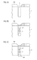
Figur 8 zeigt eine vereinfachte Teil-Draufsicht eines ultradünnen bruchfesten Halbleiterwafers gemäß einem dritten Ausführungsbeispiel, wobei gleiche Bezugszeichen wiederum gleiche oder entsprechende Elemente oder Schichten bezeichnen wie in den Figuren 1 bis 7 und auf eine wiederholte Beschreibung nachfolgend verzichtet wird.Figure 8 shows a simplified partial top view of an ultra thin break-resistant semiconductor wafers according to a third exemplary embodiment, the same reference numerals being the same or designate corresponding elements or layers such as in Figures 1 to 7 and a repeated description is subsequently waived.
Gemäß Figur 8 weist ein Sägerahmen 4 jeweils zwei voneinander
beabstandete Gräben G auf, welche mit einem der vorstehend
beschriebenen Verfahren ausgebildet bzw. aufgefüllt werden
können. Die durch den Sägerahmen 4 voneinander getrennten
Halbleiterbausteine weisen üblicherweise ein Zellenfeld ZF
mit aktiven Bauelementen, aber auch sogenannten Anschlussflächen
GP auf, welche üblicherweise auf Isolierschichten 8 ausgebildet
sind und somit zumindest zunächst nicht unmittelbar
galvanisiert werden können. Zur Realisierung einer Galvanisierung
auch von derartigen isolierten freiliegenden Bereichen,
wie sie beispielsweise die in Figur 8 dargestellten
Gate-Anschlussbereiche GP darstellen, wird demzufolge eine
Hilfsstruktur HF vorgeschlagen, die aus einem elektrisch leitenden
Material besteht und von einem Substratbereich 19 im
Sägerahmen 4 zu den isolierten freiliegenden Bereichen GP
führt. Vorzugsweise können hierfür Leiterbahnstrukturen verwendet
werden, die unmittelbar auf der Substratoberfläche
oder der Oberfläche der Isolierschicht 8 ausgebildet und
strukturiert sind.According to FIG. 8, a
Figur 9 zeigt eine vereinfachte Teil-Schnittansicht entlang eines Schnitts A-A gemäß Figur 8, wobei gleiche Bezugszeichen gleiche oder entsprechende Schichten wie in den Figuren 1 bis 8 bezeichnen und auf eine wiederholte Beschreibung nachfolgend verzichtet wird.Figure 9 shows a simplified partial sectional view along a section A-A according to Figure 8, with the same reference numerals same or corresponding layers as in Figures 1 to 8 and a repeated description below is waived.
Gemäß Figur 9 wird zum Auffüllen des freiliegenden, jedoch
durch die Isolierschicht 8 isolierten Bereichs GP für die Gate-Anschlussbereiche
eine Hilfsstruktur HF an der Oberfläche
des Halbleiterwafers 1 und zumindest an der Oberfläche der
Isolierschicht 8 im freiliegenden isolierten Bereich GP bis
zu einem Substratbereich 19 im Sägerahmen 4 beispielsweise
über einen Graben G ausgebildet und strukturiert, wodurch man
eine Kontaktierung vom Substratbereich 19 bis zum isolierten
freiliegenden Bereich GP erhält. Auf diese Weise kann auch
der isolierte freiliegende Bereich galvanisch aufgefüllt werden,
wodurch nicht nur Schubspannung verringerndes Material
sondern auch beispielsweise ein sogenannter Gate-Anschlussbereich
bzw. Gate-Pad GP mittels der vorstehend beschriebenen
Galvanisierungsverfahren ausgebildet werden kann.According to Figure 9 is used to fill up the exposed, however
area GP insulated by the insulating
Da der Gate-Anschlussbereich GP mit dem Halbleitersubstrat
über die Hilfsstruktur verbunden ist, muss es vor Benutzung
der Halbleiterbausteine von diesem wieder getrennt werden,
was im Zuge des Wafersägens bzw. Vereinzelns automatisch geschieht.
Die Linien RS deuten hierbei die Ränder der Sägespur
im Sägerahmen 4 an, wodurch die Gate-Anschlussbereiche GP vom
elektrisch leitenden Trägersubstrat getrennt werden.Since the gate connection area GP with the semiconductor substrate
connected via the auxiliary structure, it must be used before
the semiconductor components are separated from it again,
what happens automatically in the course of wafer sawing or singling.
The lines RS indicate the edges of the sawing track
in the
Figur 10 zeigt eine vereinfachte Teil-Schnittansicht eines Zellenfeldes ZF gemäß einem vierten Ausführungsbeispiel, wobei gleiche Bezugszeichen gleiche oder entsprechende Schichten bzw. Elemente bezeichnen wie in den Figuren 1 bis 9 und auf eine wiederholte Beschreibung nachfolgend verzichtet wird.Figure 10 shows a simplified partial sectional view of a Cell field ZF according to a fourth embodiment, wherein same reference numerals same or corresponding layers or designate elements as in FIGS. 1 to 9 and a repeated description is omitted below becomes.
Im Gegensatz zu der in Figur 9 dargestellten p-Wanne 9, welche
im Wesentlichen im Zellenfeld ZF ausgebildet ist, können
gemäß Figur 10 auch komplexe Halbleiterbauelemente und insbesondere
(in Abhängigkeit von einer jeweiligen Substratdicke)
Niedervolt-Leistungstransistoren oder Hochvolt-Leistungstransistoren
ausgebildet werden.In contrast to the p-
Gemäß Figur 10 werden demzufolge in einem n--Halbleitersubstrat
1 lokale p-Wannen 9A als sogenannte p-Bodies ausgebildet,
in die an der Oberfläche Sourcegebiete S eingebracht
werden. An der Oberfläche des Halbleitersubstrats 1 befinden
sich in üblicher Weise eine (nicht dargestellte) Gate-Isolationsschicht,
eine Gateschicht GS sowie eine Isolationsschicht
8, welche zu Zell-Stapeln strukturiert sind. Zwischen
jedem Zell-Stapel mit einem Ausmaß L sind ferner Kontaktlöcher
KL in das Halbleitersubstrat 1 bzw. die p-Wannen 9A sowie
durch die Sourcegebiete S hindurch ausgebildet, wodurch
die vorstehend beschriebene Galvanisierung durchgeführt werden
kann.Accordingly, according to FIG. 10, local p-
Demzufolge werden in einer ersten Phase des Galvanisierungsverfahrens
die galvanische Füllschicht 11A bis zu einer Linie
bzw. einem Niveau N1 aufgewachsen, wobei man zunächst voneinander
getrennte Galvanisierungsstöpsel bzw. -pilze erhält. In
einer nachfolgenden Phase des Galvanisierungsprozesses wachsen
diese Pilze 11A zusammen, wodurch man eine galvanische
Füllschicht 11B beispielsweise bei einer Linie bzw. einem Niveau
N2 erhält. Schließlich werden die freiliegenden Bereiche
der Galvanisierungsmaske 6 bis zu einer Linie bzw. einem Niveau
N3 mit galvanischem Füllmaterial 11C aufgefüllt, wodurch
eine im Wesentlichen gleichförmige Oberfläche entsteht. Das
erfindungsgemäße Galvanisierungsverfahren ist insbesondere
dann anwendbar, wenn das Zellraster L der Leistungstransistoren
wesentlich kleiner ist als eine Höhe H der Galvanisierungsmaske
bzw. -höcker 6.As a result, in a first phase of the electroplating process
the
Obwohl im vorliegenden Verfahren vorzugsweise das gleiche
galvanische Material als Füllschicht 11 verwendet wird, können
alternativ auch verschiedene Metalle als galvanische
Füllschichten 11A bis 11C in den frei liegenden Bereichen der
Galvanisierungsmaske 6 abgeschieden werden, wodurch beispielsweise
Barriereschichten oder sonstige elektrische Eigenschaften
(Lötbarkeit) verbessert werden können.Although preferably the same in the present process
galvanic material can be used as
Auf diese Weise können erstmals auch nur wenige µm dünne Niedervolt-Leistungstransistoren mit hoher Ausbeute und damit kostengünstig hergestellt werden.In this way, only a few µm thin low-voltage power transistors can be used with high yield and thus can be produced inexpensively.
Gemäß der vorliegenden Erfindung werden durch Ausbilden von Gräben und Auffüllen dieser Gräben mit schubspannungsfestem Material scheibenförmige Gegenstände und insbesondere Halbleiterwafer unzerbrechlich gemacht. Damit diese Gegenstände bzw. Halbleiterwafer aber nach einem Dünnen weiterhin handhabbar bleiben, werden die scheibenförmigen Gegenstände bzw. Halbleiterwafer durch Galvanisierungsmasken und dazwischen liegende galvanische Füllschichten weiter stabilisiert, wodurch man hochbruchfeste Halbleiterwafer und zugehörige Halbleiterschaltungsanordnungen erhält.According to the present invention, by forming Trenches and filling these trenches with shear stress resistant Material disk-shaped objects and in particular semiconductor wafers made unbreakable. So these items or semiconductor wafers but still manageable after thinning remain, the disc-shaped objects or Semiconductor wafers through galvanization masks and in between lying galvanic filling layers further stabilized, whereby highly break-proof semiconductor wafers and associated semiconductor circuit arrangements receives.
Die Erfindung wurde vorstehend anhand eines Silizium-Halbleiterwafers beschrieben. Sie ist jedoch nicht darauf beschränkt und umfasst in gleicher Weise auch andere Halbleitermaterialien. In gleicher Weise können als schubspannungsfeste Materialien auch andere Materialien als Fotoimid oder Kupfer verwendet werden, die ähnliche Eigenschaften zur Verringerung bzw. Verhinderung der eingangs genannten Schubspannungen aufweisen.The invention has been described above using a silicon semiconductor wafer described. However, it is not limited to this and also includes other semiconductor materials in the same way. In the same way can be used as shear stress resistant Materials other than photoimide or Copper can be used to reduce similar properties or prevention of the shear stresses mentioned at the beginning exhibit.
Claims (24)
in Schritt b) zumindest ein Graben (G1, G2) mit einer Grabentiefe (h1, h2) ausgebildet wird, die größer ist als die Enddicke (DE1, DE2) des gedünnten Trägersubstrats (1A).
in step b) at least one trench (G1, G2) is formed with a trench depth (h1, h2) which is greater than the final thickness (D E1 , D E2 ) of the thinned carrier substrate (1A).
dadurch gekennzeichnet, dass in Schritt a) ein Halbleiterwafer von einem ersten Leitungstyp (n-) verwendet wird.Method according to claim 1,
characterized in that a semiconductor wafer of a first conductivity type (n - ) is used in step a).
dadurch gekennzeichnet, dass in Schritt b) ein Laserschneiden, Plasmaätzen, nasschemisches Ätzen, lichtinduziertes Ätzen, anodisches Ätzen und/oder Sägen durchgeführt wird.Method according to claim 1 or 2,
characterized in that in step b) laser cutting, plasma etching, wet chemical etching, light-induced etching, anodic etching and / or sawing is carried out.
dadurch gekennzeichnet, dass
die Schritte c) und d) gleichzeitig durchgeführt werden. Method according to one of claims 1 to 3,
characterized in that
steps c) and d) are carried out simultaneously.
dadurch gekennzeichnet, dass ein photosensitiver Lack als schubspannungsfestes Material (SF) ganzflächig aufgeschleudert sowie in den zumindest einen Graben (G1, G2) eingebracht, und zur Ausbildung der Galvanisierungsmaske (6) fotolithographisch strukturiert wird.Method according to claim 4,
characterized in that a photosensitive lacquer as a shear stress-resistant material (SF) is spun onto the entire surface and introduced into the at least one trench (G1, G2), and is structured photolithographically to form the galvanizing mask (6).
dadurch gekennzeichnet, dass der photosensitive Lack Fotoimid darstellt.Method according to claim 5,
characterized in that the photosensitive lacquer represents photoimide.
dadurch gekennzeichnet, dass
in Schritt c) ein metallisches Material und insbesondere Wolfram als schubspannungsfestes Material (SF) im zumindest einen Graben (G) galvanisch aufgefüllt wird.Method according to one of claims 1 to 3,
characterized in that
in step c) a metallic material and in particular tungsten as shear stress-resistant material (SF) is galvanically filled in at least one trench (G).
dadurch gekennzeichnet, dass vor Schritt e) ein Schleifen zur Verringerung von Schwankungen der Anfangsdicke (DA) durchgeführt wird.Method according to one of claims 1 to 7,
characterized in that before step e) grinding is carried out to reduce fluctuations in the initial thickness (D A ).
dadurch gekennzeichnet, dass in Schritt e) eine Vielzahl von galvanischen Metallschichten ausgebildet werden.Method according to one of claims 1 to 8,
characterized in that a plurality of galvanic metal layers are formed in step e).
dadurch gekennzeichnet, dass in Schritt e) eine gleichförmige Kontaktierung des Trägersubstrats (1) von seiner Rückseite erfolgt.Method according to one of claims 1 to 9,
characterized in that in step e) there is a uniform contacting of the carrier substrate (1) from its rear side.
dadurch gekennzeichnet, dass in Schritt e) ein Vakuumchuck mit einer Vielzahl von Kontaktspitzen (13) und dazwischenliegenden Vakuumkanälen (14) für die gleichförmige Kontaktierung verwendet wird.Method according to claim 10,
characterized in that in step e) a vacuum chuck with a plurality of contact tips (13) and intermediate vacuum channels (14) is used for the uniform contacting.
dadurch gekennzeichnet, dass in Schritt f) ein mechanisches Schleifen mit nachfolgendem Spin-Ätzen und abschließendem Polieren durchgeführt wird.Method according to one of claims 1 to 11,
characterized in that in step f) mechanical grinding with subsequent spin-etching and final polishing is carried out.
dadurch gekennzeichnet, dass in Schritt f) bis zu einer Enddicke (DE1, DE2) von 5 µm bis 200 µm gedünnt wird.Method according to one of claims 1 to 12,
characterized in that in step f) is thinned to a final thickness (D E1 , D E2 ) of 5 µm to 200 µm.
dadurch gekennzeichnet, dass vor Schritt d) eine elektrisch leitende Hilfsstruktur (HS) zur Galvanisierung von isolierten freiliegenden Bereichen (GP) der Galvanisierungsmaske (6) ausgebildet wird, die mit einer Isolierschicht (8) bedeckt sind.Method according to one of claims 1 to 13,
characterized in that before step d) an electrically conductive auxiliary structure (HS) for galvanizing isolated exposed areas (GP) of the galvanizing mask (6) is formed, which are covered with an insulating layer (8).
dadurch gekennzeichnet, dass die elektrisch leitende Hilfsstruktur (HS) eine von einem Substratbereich (19) im Sägerahmen (4) zu den isolierten freiliegenden Bereichen (GP) führende Leiterbahnstruktur darstellt.Method according to claim 14,
characterized in that the electrically conductive auxiliary structure (HS) represents a conductor track structure leading from a substrate area (19) in the saw frame (4) to the isolated exposed areas (GP).
dadurch gekennzeichnet, dass die isolierten freiliegenden Bereiche Gate-Anschlussbereiche (GP) darstellen.Method according to claim 14 or 15,
characterized in that the isolated exposed areas represent gate connection areas (GP).
einem gedünnten Halbleitersubstrat (1A); und
zumindest einem Halbleiterbauelement (9; S, GS, D), welches im Halbleitersubstrat (1A) ausgebildet ist;
gekennzeichnet durch
zumindest einen Graben (G1, G2; G), der an einem Bausteinrand im Substrat (1A) ausgebildet und mit einem schubspannungsfesten Material (SF) aufgefüllt ist;
eine Galvanisierungsmaske (6), die an der Oberfläche des Halbleitersubstrats (1A) mit einer Vielzahl von freiliegenden Bereichen ausgebildet ist; und
einer galvanischen Füllschicht (11), welche die Vielzahl von freiliegenden Bereichen der Galvanisierungsmaske (6) im Wesentlichen gleichförmig auffüllt.Semiconductor circuit arrangement with
a thinned semiconductor substrate (1A); and
at least one semiconductor component (9; S, GS, D) which is formed in the semiconductor substrate (1A);
marked by
at least one trench (G1, G2; G) which is formed on a module edge in the substrate (1A) and is filled with a shear stress-resistant material (SF);
a plating mask (6) formed on the surface of the semiconductor substrate (1A) with a plurality of exposed areas; and
a galvanic filling layer (11) which fills the plurality of exposed areas of the galvanizing mask (6) essentially uniformly.
dadurch gekennzeichnet, dass die Galvanisierungsmaske (6) unmittelbar über dem zumindest einen Graben (G1, G2; G) ausgebildet ist und das gleiche Material aufweist wie das schubspannungsfeste Material (SF) des zumindest einen Grabens (G1, G2; G).Semiconductor circuit arrangement according to claim 17,
characterized in that the galvanizing mask (6) is formed directly above the at least one trench (G1, G2; G) and has the same material as the shear stress-resistant material (SF) of the at least one trench (G1, G2; G).
dadurch gekennzeichnet, dass das schubspannungsfeste Material (SF) des zumindest einen Grabens (G1, G2; G) und das Material der Galvanisierungsmaske (6) einen photosensitiven Lack und insbesondere Photoimid aufweist.Semiconductor circuit arrangement according to claim 18,
characterized in that the shear stress-resistant material (SF) of the at least one trench (G1, G2; G) and the material of the galvanizing mask (6) has a photosensitive lacquer and in particular photoimide.
dadurch gekennzeichnet, dass das schubspannungsfeste Material (SF) des zumindest einen Grabens (G1, G2; G) eine galvanische Füllschicht und insbesondere Wolfram aufweist.Semiconductor circuit arrangement according to claim 17,
characterized in that the shear stress-resistant material (SF) of the at least one trench (G1, G2; G) has a galvanic filling layer and in particular tungsten.
Applications Claiming Priority (2)
| Application Number | Priority Date | Filing Date | Title |
|---|---|---|---|
| DE10326507 | 2003-06-12 | ||
| DE2003126507 DE10326507A1 (en) | 2003-06-12 | 2003-06-12 | A method of making a fracture resistant disc shaped article and associated semiconductor circuit assembly |
Publications (2)
| Publication Number | Publication Date |
|---|---|
| EP1489656A2 true EP1489656A2 (en) | 2004-12-22 |
| EP1489656A3 EP1489656A3 (en) | 2006-03-08 |
Family
ID=33394818
Family Applications (1)
| Application Number | Title | Priority Date | Filing Date |
|---|---|---|---|
| EP04101941A Withdrawn EP1489656A3 (en) | 2003-06-12 | 2004-05-05 | Method of fabrication of an unbreakable disc-shaped object and corresponding semiconductor circuit |
Country Status (2)
| Country | Link |
|---|---|
| EP (1) | EP1489656A3 (en) |
| DE (1) | DE10326507A1 (en) |
Cited By (2)
| Publication number | Priority date | Publication date | Assignee | Title |
|---|---|---|---|---|
| EP1505638A3 (en) * | 2003-06-12 | 2009-03-11 | Infineon Technologies AG | Method of producing of a break-proof plate-like object, and corresponding semiconductor circuit |
| CN111540706A (en) * | 2020-04-22 | 2020-08-14 | 创能动力科技有限公司 | Method for producing a semiconductor wafer with a support structure |
Families Citing this family (1)
| Publication number | Priority date | Publication date | Assignee | Title |
|---|---|---|---|---|
| DE102007043902A1 (en) * | 2007-09-14 | 2009-03-19 | Osram Opto Semiconductors Gmbh | Method for isolating semiconductor components with metallization of compound, involves separating portions of metallization according to partition into semiconductor components by residual portion of photo resist layer |
Citations (5)
| Publication number | Priority date | Publication date | Assignee | Title |
|---|---|---|---|---|
| US5104820A (en) * | 1989-07-07 | 1992-04-14 | Irvine Sensors Corporation | Method of fabricating electronic circuitry unit containing stacked IC layers having lead rerouting |
| US5618752A (en) * | 1995-06-05 | 1997-04-08 | Harris Corporation | Method of fabrication of surface mountable integrated circuits |
| US5691248A (en) * | 1995-07-26 | 1997-11-25 | International Business Machines Corporation | Methods for precise definition of integrated circuit chip edges |
| US20020127868A1 (en) * | 1996-10-29 | 2002-09-12 | Oleg Siniaguine | Integrated circuits and methods for their fabrication |
| US20030085460A1 (en) * | 1996-10-29 | 2003-05-08 | Oleg Siniaguine | Integrated circuits and methods for their fabrication |
Family Cites Families (2)
| Publication number | Priority date | Publication date | Assignee | Title |
|---|---|---|---|---|
| CA2118994A1 (en) * | 1993-06-21 | 1994-12-22 | Claude L. Bertin | Polyimide-insulated cube package of stacked semiconductor device chips |
| US20030189215A1 (en) * | 2002-04-09 | 2003-10-09 | Jong-Lam Lee | Method of fabricating vertical structure leds |
-
2003
- 2003-06-12 DE DE2003126507 patent/DE10326507A1/en not_active Ceased
-
2004
- 2004-05-05 EP EP04101941A patent/EP1489656A3/en not_active Withdrawn
Patent Citations (5)
| Publication number | Priority date | Publication date | Assignee | Title |
|---|---|---|---|---|
| US5104820A (en) * | 1989-07-07 | 1992-04-14 | Irvine Sensors Corporation | Method of fabricating electronic circuitry unit containing stacked IC layers having lead rerouting |
| US5618752A (en) * | 1995-06-05 | 1997-04-08 | Harris Corporation | Method of fabrication of surface mountable integrated circuits |
| US5691248A (en) * | 1995-07-26 | 1997-11-25 | International Business Machines Corporation | Methods for precise definition of integrated circuit chip edges |
| US20020127868A1 (en) * | 1996-10-29 | 2002-09-12 | Oleg Siniaguine | Integrated circuits and methods for their fabrication |
| US20030085460A1 (en) * | 1996-10-29 | 2003-05-08 | Oleg Siniaguine | Integrated circuits and methods for their fabrication |
Cited By (2)
| Publication number | Priority date | Publication date | Assignee | Title |
|---|---|---|---|---|
| EP1505638A3 (en) * | 2003-06-12 | 2009-03-11 | Infineon Technologies AG | Method of producing of a break-proof plate-like object, and corresponding semiconductor circuit |
| CN111540706A (en) * | 2020-04-22 | 2020-08-14 | 创能动力科技有限公司 | Method for producing a semiconductor wafer with a support structure |
Also Published As
| Publication number | Publication date |
|---|---|
| EP1489656A3 (en) | 2006-03-08 |
| DE10326507A1 (en) | 2005-01-13 |
Similar Documents
| Publication | Publication Date | Title |
|---|---|---|
| DE10315780B4 (en) | Production process for semiconductor devices | |
| DE102016117562B4 (en) | SEMICONDUCTOR CHIP WITH STRUCTURED SIDEWALLS AND METHOD FOR PRODUCING SAME | |
| DE102006052202B3 (en) | Semiconductor component has metal layer comprising coherent section, and other metal layer is arranged on coherent section of former metal layer, where latter metal layer is structured between layered regions | |
| EP1171912A1 (en) | Method for the vertical integration of electric components by | |
| DE102013112797B4 (en) | ARRANGEMENT WITH SEMICONDUCTOR DEVICE INCLUDING CHIP CARRIER, SEMICONDUCTOR WAFER AND METHOD OF MANUFACTURING SEMICONDUCTOR DEVICE | |
| EP0666595A1 (en) | Method of manufacture of a cubic integrated circuit structure | |
| DE102004052921A1 (en) | Process for the production of semiconductor devices with external contacts | |
| DE112013001641T5 (en) | Solar cell and method for producing a solar cell | |
| DE102009044060A1 (en) | Method for contacting wafer solar cell of e.g. solar cell string in solar cell module, involves arranging connectors on bonding surface of solar cell to bond connectors on bonding surface that lies opposite to bearing surface | |
| EP0698293B1 (en) | Method of manufacturing a semiconductor component with supply terminals for high integration density | |
| DE1924712C3 (en) | Integrated thin-film blocking or Decoupling capacitor for monolithic circuits and method for its manufacture | |
| DE102015110437A1 (en) | A semiconductor device having a metal structure electrically connected to a conductive structure | |
| DE102006043163B4 (en) | Semiconductor circuitry | |
| DE102009005458A1 (en) | Semiconductor component with through-hole and method for its production | |
| EP1489656A2 (en) | Method of fabrication of an unbreakable disc-shaped object and corresponding semiconductor circuit | |
| DE102008036285B4 (en) | Integrated circuit having a connection to a heat sink produced by a galvanic process and method therefor | |
| WO2009156382A2 (en) | Method for production of a thermoelectric apparatus | |
| DE102018103169A1 (en) | Method for producing a semiconductor component and semiconductor component | |
| DE102008033223A1 (en) | Contact-structure producing method for solar cell, involves tempering semiconductor-substrate with germination layer for diffusion of dopant from germination layer into semiconductor-substrate | |
| DE112021000892T5 (en) | SEMICONDUCTOR DEVICE, A SEMICONDUCTOR HOUSING HAVING THEM, AND METHOD FOR MANUFACTURING A SEMICONDUCTOR DEVICE | |
| DE102012014428B4 (en) | METHOD OF MAKING CONTACT TERMINAL AND INTEGRATED CIRCUIT CHIP | |
| DE102018112979A1 (en) | MONOLITHIC INTEGRATED CHIP INCLUDING ACTIVE ELECTRICAL COMPONENTS AND PASSIVE ELECTRICAL COMPONENTS WITH CHIP KANTE STABILIZATION STRUCTURES | |
| DE102014103540B4 (en) | SEMICONDUCTOR COMPONENT AND INTEGRATED CIRCUIT | |
| DE102012111831A1 (en) | Integrated circuit and method for manufacturing an integrated circuit | |
| EP1505638B1 (en) | Method of producing of a break-proof plate-like object, and corresponding semiconductor circuit |
Legal Events
| Date | Code | Title | Description |
|---|---|---|---|
| PUAI | Public reference made under article 153(3) epc to a published international application that has entered the european phase |
Free format text: ORIGINAL CODE: 0009012 |
|
| AK | Designated contracting states |
Kind code of ref document: A2 Designated state(s): AT BE BG CH CY CZ DE DK EE ES FI FR GB GR HU IE IT LI LU MC NL PL PT RO SE SI SK TR |
|
| AX | Request for extension of the european patent |
Extension state: AL HR LT LV MK |
|
| PUAL | Search report despatched |
Free format text: ORIGINAL CODE: 0009013 |
|
| AK | Designated contracting states |
Kind code of ref document: A3 Designated state(s): AT BE BG CH CY CZ DE DK EE ES FI FR GB GR HU IE IT LI LU MC NL PL PT RO SE SI SK TR |
|
| AX | Request for extension of the european patent |
Extension state: AL HR LT LV MK |
|
| 17P | Request for examination filed |
Effective date: 20060413 |
|
| AKX | Designation fees paid |
Designated state(s): DE |
|
| STAA | Information on the status of an ep patent application or granted ep patent |
Free format text: STATUS: THE APPLICATION IS DEEMED TO BE WITHDRAWN |
|
| 18D | Application deemed to be withdrawn |
Effective date: 20080201 |