EP1491157B1 - Surgical anchor inserter - Google Patents
Surgical anchor inserter Download PDFInfo
- Publication number
- EP1491157B1 EP1491157B1 EP04253819A EP04253819A EP1491157B1 EP 1491157 B1 EP1491157 B1 EP 1491157B1 EP 04253819 A EP04253819 A EP 04253819A EP 04253819 A EP04253819 A EP 04253819A EP 1491157 B1 EP1491157 B1 EP 1491157B1
- Authority
- EP
- European Patent Office
- Prior art keywords
- cannulated
- sleeve
- pin
- inserter
- cannulated sleeve
- Prior art date
- Legal status (The legal status is an assumption and is not a legal conclusion. Google has not performed a legal analysis and makes no representation as to the accuracy of the status listed.)
- Expired - Fee Related
Links
Images


Classifications
-
- A—HUMAN NECESSITIES
- A61—MEDICAL OR VETERINARY SCIENCE; HYGIENE
- A61B—DIAGNOSIS; SURGERY; IDENTIFICATION
- A61B17/00—Surgical instruments, devices or methods, e.g. tourniquets
- A61B17/068—Surgical staplers, e.g. containing multiple staples or clamps
- A61B17/0682—Surgical staplers, e.g. containing multiple staples or clamps for applying U-shaped staples or clamps, e.g. without a forming anvil
-
- A—HUMAN NECESSITIES
- A61—MEDICAL OR VETERINARY SCIENCE; HYGIENE
- A61B—DIAGNOSIS; SURGERY; IDENTIFICATION
- A61B17/00—Surgical instruments, devices or methods, e.g. tourniquets
- A61B17/064—Surgical staples, i.e. penetrating the tissue
- A61B17/0642—Surgical staples, i.e. penetrating the tissue for bones, e.g. for osteosynthesis or connecting tendon to bone
-
- A—HUMAN NECESSITIES
- A61—MEDICAL OR VETERINARY SCIENCE; HYGIENE
- A61B—DIAGNOSIS; SURGERY; IDENTIFICATION
- A61B17/00—Surgical instruments, devices or methods, e.g. tourniquets
- A61B17/064—Surgical staples, i.e. penetrating the tissue
- A61B2017/0647—Surgical staples, i.e. penetrating the tissue having one single leg, e.g. tacks
-
- A—HUMAN NECESSITIES
- A61—MEDICAL OR VETERINARY SCIENCE; HYGIENE
- A61B—DIAGNOSIS; SURGERY; IDENTIFICATION
- A61B17/00—Surgical instruments, devices or methods, e.g. tourniquets
- A61B17/56—Surgical instruments or methods for treatment of bones or joints; Devices specially adapted therefor
- A61B17/58—Surgical instruments or methods for treatment of bones or joints; Devices specially adapted therefor for osteosynthesis, e.g. bone plates, screws, setting implements or the like
- A61B17/88—Osteosynthesis instruments; Methods or means for implanting or extracting internal or external fixation devices
- A61B17/92—Impactors or extractors, e.g. for removing intramedullary devices
- A61B2017/922—Devices for impaction, impact element
Landscapes
- Health & Medical Sciences (AREA)
- Life Sciences & Earth Sciences (AREA)
- Surgery (AREA)
- Molecular Biology (AREA)
- General Health & Medical Sciences (AREA)
- Biomedical Technology (AREA)
- Heart & Thoracic Surgery (AREA)
- Medical Informatics (AREA)
- Nuclear Medicine, Radiotherapy & Molecular Imaging (AREA)
- Animal Behavior & Ethology (AREA)
- Engineering & Computer Science (AREA)
- Public Health (AREA)
- Veterinary Medicine (AREA)
- Orthopedic Medicine & Surgery (AREA)
- Rheumatology (AREA)
- Surgical Instruments (AREA)
- Prostheses (AREA)
Description
- The present invention relates to surgical instruments, and, more specifically, to an inserter for simultaneously deploying a plurality of anchors to secure a surgical construct to bone.
- Single level spine fusion procedures typically entail removing the intervertebral disk and inserting an interbody device into the disk space. Current spine fusion procedures rely heavily on the use of posterior fixation to achieve the stability and rigidity necessary to obtain successful clinical results. However, implantation of posterior instrumentation necessarily involves removing important musculoskeletal elements. Because of these concerns, anterior fixation systems have also been developed which require removal of much less musculoskeletal mass. However, because anterior fixation, especially in the abdominal or thoracic area, lies in close proximity to vital internal organs (e.g., the aorta), these fixation systems must also possess a low profile.
- In general, conventional intervertebral connection systems can be characterized by ligament components that are either: (1) relatively rigid; or (2) not shaped for cooperative connection to bone anchors; or (3) by bone anchors that are shouldered to seat upon the vertebral surface. When the ligament is relatively rigid, it must essentially lie fully upon the anterior surfaces of the adjacent vertebrae, thereby limiting design options. Systems having relatively rigid ligaments typically have transverse holes near their end portions for accepting bone anchors. In systems in which the ligament is not shaped for cooperative attachment to the bone anchor, attachment is typically made by either suturing or by passing a screw through the ligament. When the bone anchor is seated upon the vertebral surface, a portion of the bone anchor protrudes from the surface and the tension of the ligament cannot be further adjusted.
- In commonly-owned
U.S. Patent Application No. 09/822,126 , entitled "Intervertebral Connection System", filed March 30,2001, and published asUS 2002/0143329 there is disclosed an intervertebral connection system comprising a ligament having a central portion, first and second end portions, first and second conformable portions, and first and second shoulderless bone anchors. The shoulderless feature of the bone anchor allows the bone anchor to be fully driven into the vertebral surface, thereby eliminating any problematic protrusion while also providing a means to adjust the tension of the ligament after the bone anchors have been located. The conformable portions of the ligament allow the ligament to conform to the recess produced by a fully driven bone fastener without generating undue stress, thereby accommodating the surgeon's desire to fully drive the bone fastener within the recess. The cooperative shape of the ligament end portions allows for non-destructive attachment of the ligament to the bone anchors without the use of sutures, thereby minimizing unwanted connection-related stresses and undesirable generation of foreign particles within the patient. - In commonly-owned
U.S. Patent Application No. 10/112,619 , entitled "Expandable Cable Anchor", filed March 29, 2002, and published asUS 2003/0187444 , there is disclosed a bone anchoring device for securing suture or cable within a bone hole. The bone anchoring device includes a radially expandable sheath, an expander member for expanding the sheath, and a washer. As disclosed in the application, two bone anchoring devices could be connected via a cable and used to hold a bone block between adjacent vertebrae in spinal fusion procedures. - Bone anchors for attaching soft tissue or sutures to bone are well known in the art. Also well known in the art are inserter tools for deploying such bone anchors in a hole in bone tissue. All of the known art describes deployment of a single anchor to secure a structure to bone.
- In the case of multiple anchor surgical constructs, such as the intervertebral connection system described above, there is a need for an inserter that can simultaneously deploy a plurality of bone anchors. More specifically, an inserter is needed wherein a surgical construct, comprising two or more anchors connected by a ligament or cable, can be readily assembled to the inserter for delivery and simultaneous deployment of the anchors into holes in bone.
-
US 2002/0095064 discloses a stapler including two barrels that have respective staple guides at the free ends thereof. The staple guides receive staples which are ejected therefrom by ejector pins received in the respective barrels: depression of a trigger causes high-pressure pulses of air to drive the pins into the staples to facilitate ejection thereof, and ultimately to introduce the staples into tissue. - The problems and disadvantages of the prior art devices described above are overcome in accordance with the present invention by providing a new and improved surgical anchor inserter as defined in claim 1 which is specifically adapted to simultaneously deploy multiple surgical anchors. More particularly, the new and improved inserter includes at least a pair of receiving mechanisms or means, each of which can be in the form of a receptacle such as a cannulated sleeve sized and shaped so as to accommodate a surgical anchor therein. The inserter also includes at least a pair of ejecting mechanisms or means, one for each of the receiving means. Each of the ejecting means can be in the form of a cannulated pin which functions to eject a surgical anchor from an associated receiving means in response to relative movement between the associated receiving means and its corresponding ejecting means. All of the ejecting means can be activated by a single actuating mechanism or means, such as a manually grippable handle which initiates the movement of the ejecting means relative to the receiving means.
- For a better understanding of the present invention, reference is made to the following detailed description of an exemplary embodiment considered in conjunction with the accompanying drawings, in which:
-
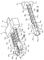
Figure 1 is a perspective view of a dual anchor inserter constructed in accordance with one exemplary embodiment of the present invention; -
Figure 2 is a perspective view of the distal end of the dual anchor inserter depicted inFigure 1 ; -
Figure 3 is a perspective view of the right leg of the dual anchor inserter depicted inFigures 1 and2 ; -
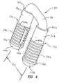
Figure 4 is a perspective view of a dual anchor surgical construct adapted use with the dual anchor inserter ofFigures 1-3 ; -
Figure 5 is a perspective view showing the dual anchor inserter ofFigures 1-3 in an assembled configuration with the surgical construct ofFigure 4 ; -
Figure 6 is a partial cross-sectional view of the left leg of the assembly depicted inFigure 5 ; -
Figure 7 is a side elevational view of the assembly depicted inFigure 5 prior to its deployment in a pair of bone holes; -
Figure 8 is a side elevational view of the assembly depicted inFigure 5 during its deployment in a pair of bone holes; and -
Figure 9 is a side elevational view of the assembly depicted inFigure 5 after it has been fully deployed in a pair of bone holes. - Referring initially to
Figures 1-3 , there is shown adual anchor inserter 10 for use in anchoring a dual anchor surgical construct to bones of an affected patient. Theinserter 10 includes ahandle 12, which is sized and shaped so as be grippable by the hand of a surgeon, and ahead 14, which is immovably attached on oneside 16 thereof to thehandle 12, whereby thehandle 12 and thehead 14 move conjointly. A dualanchor deployment assembly 18 is attached to anopposite side 20 of thehead 14. - With particular reference to
Figures 2 and 3 , the dualanchor deployment assembly 18 includes a pair of essentiallyidentical pins head 14 to a free ordistal end Figures 3 and6 ). Both of thepins pin cutout Figures 3 and6 ), whereby each of thepins pins head 14 such that they extend in parallel fashion at a spaced apart distance D1 with theircutouts pins slots slots proximal end distal end 32a, 32b, respectively (seeFigures 2, 3 and6 ). - Still referring to
Figures 2 and 3 , the dualanchor deployment assembly 18 also includes a pair of essentially identicalcylindrical sleeves 34a, 34b, each of which is coaxially mounted on a corresponding one of thepins sleeves 34a, 34b includes aproximal end 36a, 36b, respectively, and adistal end 38a, 38b, respectively. Like thepins sleeves 34a, 34b have cutouts 39a, 39b, respectively, thereby providing each of thesleeves 34a, 34b with a generally C-shaped lateral cross section. - Focusing initially on the
sleeve 34a, it also includes an innerannular shoulder 40a positioned intermediate its proximal anddistal ends sleeve 34a into asmall diameter portion 42a and alarge diameter portion 44a. The inner diameter of thesmall diameter portion 42a is slightly larger than the outer diameter of thepin 22a, thereby allowing thesleeve 34a to slide or otherwise move back and forth over thefree end 24a of thepin 22a. Apeg 46a (seeFigure 3 ) extends radially into thesmall diameter portion 42a of thesleeve 34a. When thesleeve 34a is mounted on thepin 22a, thepeg 46a is slidably received in theslot 28a of thepin 22a. Aspring 48a is positioned between theside 20 of thehead 14 and theproximal end 36a of thesleeve 34a such that thespring 48a urges thesleeve 34a into an extended position in which thepeg 46a engages thedistal end 32a of theslot 28a in thepin 22a, thereby preventing the ejection of thesleeve 34a from thepin 22a. - Turning now to the sleeve 34b, it further includes an inner annular shoulder 40b (see
Figure 6 ) positioned intermediate its proximal and distal ends 36b, 38b, thereby dividing the sleeve 34b into asmall diameter portion 42b and alarge diameter portion 44b. The inner diameter of thesmall diameter portion 42b is slightly larger than the outer diameter of thepin 22b, thereby allowing the sleeve 34b to slide or otherwise move back and forth over thefree end 24b of thepin 22b (seeFigure 6 ). A peg 46b (Figure 2 ) extends radially into thesmall diameter portion 42b of the sleeve 34b. When the sleeve 34b is mounted on thepin 22b, the peg 46b is slidably received in theslot 28b of thepin 22b. Aspring 48b is positioned between theside 20 of thehead 14 and the proximal end 36b of the sleeve 34b such that thespring 48b urges the sleeve 34b into an extended position in which the peg 46b engages the distal end 32b of the slot 20b in thepin 22b, thereby preventing the ejection of the sleeve 34b from thepin 22b. - With reference to
Figure 4 , there is shown a dual anchorsurgical construct 50, which is specifically adapted for use as an intervertebral connection system. More particularly, thesurgical construct 50 includes a pair ofanchor assemblies 51b comprising expanders sheaths washers cable 58, which has bending flexibility and axial stiffness, passes axially through theanchor assemblies U-shaped cable 58 terminates in a pair of enlarged,hemispherical tips expanders sheaths washers cable 58. Theexpanders proximal surfaces sheaths proximal surfaces 64a, 64b, respectively. Thesheaths Figures 4 and6 ). - Referring now to
Figures 5 and6 , thedual anchor inserter 10 is shown assembled to thesurgical construct 50 with both of theexpanders sheaths sleeves 34a, 34b, respectively. The inner diameter of thesmall diameter portions sleeves 34a, 34b is slightly larger than the outer diameter of theexpanders expanders respective sleeves 34a, 34b. The inner diameter of thelarge diameter portions sleeves 34a, 34b is slightly smaller than the outermost diameter of thesheaths sheaths respective sleeves 34a, 34b. Thesurgical construct 50 is fully assembled to thedual anchor inserter 10 when theproximal surfaces expanders free ends pins Figure 4 ) is equal to the distance D1 (seeFigure 2 ). When thesurgical construct 50 is fully assembled to thedual anchor inserter 10, thecable tips sheaths respective sleeves 34a, 34b (seeFigure 5 ). - The cutouts 39a, 39b in the
sleeves 34a, 34b allow thecable 58 to span the distance D1 directly between theexpanders cutouts pins expanders free ends pins proximal surfaces expanders cable 58. The inner diameter of thepins cable 58. -
Figures 7-9 show thedual anchor inserter 10 in an assembled configuration with thesurgical construct 50, when deployed in a pair ofbone holes 68a, 68b in order to anchor thecable 58 in two locations inbone 70. Each of these figures will be described in greater detail hereinafter. -
Figure 7 shows the initial deployment configuration of the assembly, demonstrating the placement of theexpanders sheaths washers cable 58 within thebone holes 68a, 68b. The diameter of thebone holes 68a, 68b is slightly larger than the outer diameter of thewashers pins bone holes 68a, 68b, respectively; guiding thecable tips bone holes 68a, 68b, respectively; and then applying a downward force to thehandle 12 to drive theanchor assemblies bone holes 68a, 68b, respectively. When thedistal ends 38a, 38b of thesleeves 34a, 34b contactouter surface 72 of thebone 70, continued downward force on thehandle 12 forces thesleeves 34a, 34b to slide along thepins head 14, thereby allowing theanchor assemblies bone holes 68a, 68b below thebone surface 72. - Referring to
Figure 8 , after theproximal surfaces expanders bone surface 72, continued downward force on thehandle 12 is resisted by tension in thecable 58. The resulting tension incable 58 serves as the reaction force to hold thesheaths expanders pins sheaths handle 12. -
Figure 9 shows the final configuration after deployment of theexpanders sheaths proximal surfaces expanders proximal surfaces 64a, 64b of thesheaths expanders sheaths sheaths sheaths bone holes 68a, 68b with an interference fit. The outer diameter of thepins bone holes 68a, 68b so that thepins respective bone holes 68a, 68b. -
Figures 7-9 show thesurgical construct 50 being deployed in asingle bone 70. However, when used as an intervertebral connection system thesurgical construct 50 would hold a bone block between adjacent vertebrae in spinal fusion procedures. In such cases, the twoanchor assemblies - The embodiment described herein is merely exemplary and hence it is susceptible to variation and modification without departing from the scope of the present invention. All such variations and modifications are intended to be included within the scope of the invention as defined in the appended claims.
Claims (14)
- An inserter (10) for multiple surgical anchors (51a, 51b), comprising:a first cannulated sleeve (34a) which is sized and shaped so as to receive a surgical anchor (51a) therein, said first cannulated sleeve (34a) having a generally C-shaped lateral cross section so as to define a first sleeve cutout (39a) therein;a first cannulated pin (22a) having a generally C-shaped lateral cross section so as to define a first pin cutout (26a) therein, said first cannulated sleeve (34a) being mounted on said first cannulated pin (22a) for reciprocating movement relative thereto for ejecting said surgical anchor (51a) therefrom;a second cannulated sleeve (34b) which is sized and shaped so as to receive another surgical anchor (51b) therein, said second cannulated sleeve (34b) having a generally C-shaped lateral cross section so as to define a second sleeve cutout (39b) therein, said first and second sleeves (34a, 34b) being arranged so that said first and second sleeve cutouts (39a, 39b) are adapted to receive a cable (58) connecting surgical anchors (51a, 51b) received in said first and second cannulated sleeves (34a, 34b), respectively;a second cannulated pin (22b) having a generally C-shaped lateral cross section so as to define a second pin cutout (26b) therein, said second cannulated sleeve (34b) being mounted on said second cannulated pin (22b) for reciprocating movement relative thereto for ejecting said another surgical anchor (51b) therefrom, said first and second cannulated pins (22a, 22b) being arranged so that said first and second pin cutouts (26a, 26b) are adapted to receive a cable (58) connecting surgical anchors (51a, 51b) received in said first and second cannulated sleeves (34a, 34b), respectively; andactuating means (12) for simultaneously reciprocating said first and second cannulated sleeves (34a, 34b) relative to said first and second cannulated pins (22a, 22b), respectively, whereby surgical anchors (51a, 51b) are simultaneously ejected from said first and second cannulated sleeves (34a, 34b), respectively.
- An inserter (10) according to Claim 1, wherein said first cannulated sleeve (34a) is mounted on a free end (24a) of said first cannulated pin (22a) and wherein said second cannulated sleeve (34b) is mounted on a free end (24b) of said second cannulated (22b) pin.
- An inserter (10) according to Claim 2, wherein said first cannulated sleeve (34b) is movable between an extended position, in which said free end (24a) of said first cannulated pin (22a) is positioned within said first cannulated sleeve (34a) adjacent one end thereof (36a), and a retracted position, in which said free end (24a) of said first cannulated pin (22a) extends outwardly from an opposite end (38a) of said first cannulated sleeve (34a), and wherein said second cannulated sleeve (34b) is movable between an extended position, in which said free end (24b) of said second cannulated pin (22b) is positioned within said second cannulated sleeve (34b) adjacent one (36b) end thereof, and a retracted position, in which said free end (24b) of said second cannulated pin (22b) extends outwardly from an opposite end (38b) of said second cannulated sleeve (34b).
- An inserter (10) according to claim 3, wherein said first cannulated sleeve (34a) ejects one surgical anchor (51a) therefrom in response to the movement of said first cannulated sleeve (34a) from its said extended position to its said retracted position, and wherein said second cannulated sleeve (34b) ejects said another surgical anchor (51b) therefrom in response to the movement of said second cannulated sleeve (34b) from its said extended position to its said retracted position.
- An inserter (10) according to claim 4, further comprising a first spring (48a) for urging said first cannulated sleeve (34a) into its said extended position and a second spring (48b) for urging said second cannulated sleeve (34b) into its said extended position.
- An inserter (10) according to Claim 5, further comprising a head (14), said first and second cannulated pins (22a, 22b) extending outwardly from one side (20) of said head (14) in a spaced parallel relationship to one another.
- An inserter according to Claim 6, wherein said first spring (48a) is interposed between said one side (20) of said head (14) and said one end (36a) of said first cannulated sleeve (34a) and wherein said second spring (48b) is interposed between said one side (20) of said head (14) and said one end (36b) of said second cannulated sleeve (34b).
- An inserter (10) according to Claim 7, wherein said first cannulated sleeve (34a) includes a first peg (46a) which extends radially thereinto and wherein said second cannulated sleeve (34b) includes a second peg (46b) which extends radially thereinto.
- An inserter (10) according to Claim 8, wherein said first cannulated pin (22a) includes a first slot (28a) extending longitudinally therealong, said first slot (28a) being sized and shaped so as to slidably receive said first peg (46a), and wherein said second cannulated pin (22b) includes a second slot (28b) extending longitudinally therealong, said second slot (28b) being sized and shaped so as to slidably receive said second peg (46b).
- An inserter (10) according to Claim 9, wherein said first peg (46a) engages an end (32a) of said first slot (28a) when said first cannulated sleeve (34a) is in its said extended position, thereby preventing said first spring (48a) from pushing said first cannulated sleeve (34a) off of said free end (24a) of said first cannulated pin (22a), and wherein said second peg (46b) engages an end (32b) of said second slot (28b) when said second cannulated sleeve (34b) is in its said extended position, thereby preventing said second spring (48b) from pushing said second cannulated sleeve (34b) off of said free end (24b) of said second cannulated pin (22b).
- An inserter (10) according to Claim 10, wherein said actuating means (12) includes a manually grippable handle (12) extending outwardly from an opposite side (16) of said head (14).
- An inserter (10) according to Claim 11, wherein said handle (12), said head (14) and said first and second cannulated pins (22a, 22b) are movable conjointly with each other.
- An inserter (10) according to Claim 6, wherein said opposite end (38a) of said first cannulated sleeve (34a) has an inner diameter selected so as to create an interference fit with a sheath portion (54a) of one surgical anchor (51a) and wherein said opposite end (38b) of said second cannulated sleeve (34b) has an inner diameter selected so as to create an interference fit with a sheath portion (54b) of another surgical anchor (51b).
- An inserter (10) according to Claim 13, wherein said free end (24a) of said first cannulated pin (22a) is adapted to move an expander portion (52a) of one surgical anchor (51a) into an associated sheath portion (54a) of the one surgical anchor (51a) as said first cannulated sleeve (34a) moves towards its said retracted position, and wherein said free end (24b) of said second cannulated pin (22b) is adapted to move an expander portion (52b) of another surgical anchor (51b) into an associated sheath portion (54b) of another surgical anchor (51b) as said second cannulated sleeve (34b) moves towards its said retracted position.
Applications Claiming Priority (2)
| Application Number | Priority Date | Filing Date | Title |
|---|---|---|---|
| US609336 | 2003-06-28 | ||
| US10/609,336 US7104999B2 (en) | 2003-06-28 | 2003-06-28 | Surgical anchor inserter |
Publications (2)
| Publication Number | Publication Date |
|---|---|
| EP1491157A1 EP1491157A1 (en) | 2004-12-29 |
| EP1491157B1 true EP1491157B1 (en) | 2008-11-26 |
Family
ID=33418746
Family Applications (1)
| Application Number | Title | Priority Date | Filing Date |
|---|---|---|---|
| EP04253819A Expired - Fee Related EP1491157B1 (en) | 2003-06-28 | 2004-06-25 | Surgical anchor inserter |
Country Status (7)
| Country | Link |
|---|---|
| US (1) | US7104999B2 (en) |
| EP (1) | EP1491157B1 (en) |
| JP (1) | JP4619702B2 (en) |
| AU (1) | AU2004202723B2 (en) |
| CA (1) | CA2472657C (en) |
| DE (1) | DE602004017934D1 (en) |
| ES (1) | ES2316934T3 (en) |
Cited By (1)
| Publication number | Priority date | Publication date | Assignee | Title |
|---|---|---|---|---|
| US10653415B2 (en) | 2009-06-04 | 2020-05-19 | Rotation Medical, Inc. | Methods and apparatus having bowstring-like staple delivery to a target tissue |
Families Citing this family (79)
| Publication number | Priority date | Publication date | Assignee | Title |
|---|---|---|---|---|
| US6524317B1 (en) | 1999-12-30 | 2003-02-25 | Opus Medical, Inc. | Method and apparatus for attaching connective tissues to bone using a knotless suture anchoring device |
| US6582453B1 (en) * | 2000-07-14 | 2003-06-24 | Opus Medical, Inc. | Method and apparatus for attaching connective tissues to bone using a suture anchoring device |
| US6770076B2 (en) | 2001-02-12 | 2004-08-03 | Opus Medical, Inc. | Method and apparatus for attaching connective tissues to bone using a knotless suture anchoring device |
| US6547800B2 (en) | 2001-06-06 | 2003-04-15 | Opus Medical, Inc. | Method and apparatus for attaching connective tissues to bone using a cortical bone anchoring device |
| US20120145765A1 (en) | 2002-06-25 | 2012-06-14 | Peterson James A | Mechanical method and apparatus for bilateral tissue fastening |
| US7087064B1 (en) | 2002-10-15 | 2006-08-08 | Advanced Cardiovascular Systems, Inc. | Apparatuses and methods for heart valve repair |
| US9149602B2 (en) | 2005-04-22 | 2015-10-06 | Advanced Cardiovascular Systems, Inc. | Dual needle delivery system |
| US7404824B1 (en) | 2002-11-15 | 2008-07-29 | Advanced Cardiovascular Systems, Inc. | Valve aptation assist device |
| US7981152B1 (en) | 2004-12-10 | 2011-07-19 | Advanced Cardiovascular Systems, Inc. | Vascular delivery system for accessing and delivering devices into coronary sinus and other vascular sites |
| US8187324B2 (en) * | 2002-11-15 | 2012-05-29 | Advanced Cardiovascular Systems, Inc. | Telescoping apparatus for delivering and adjusting a medical device in a vessel |
| US7998112B2 (en) | 2003-09-30 | 2011-08-16 | Abbott Cardiovascular Systems Inc. | Deflectable catheter assembly and method of making same |
| US7682374B2 (en) | 2003-10-21 | 2010-03-23 | Arthrocare Corporation | Knotless suture lock and bone anchor implant method |
| US8092528B2 (en) | 2005-05-27 | 2012-01-10 | Depuy Spine, Inc. | Intervertebral ligament having a helical bone fastener |
| GB2441266B (en) | 2005-06-01 | 2011-03-02 | Arthrocare Corp | Knotless suture anchoring device having deforming section to accommodate sutures of various diameters |
| US20070100351A1 (en) * | 2005-10-31 | 2007-05-03 | Deffenbaugh Daren L | Multiple suture anchor delivery device, suture anchor delivery kit and associated method |
| US20070100350A1 (en) * | 2005-10-31 | 2007-05-03 | Deffenbaugh Daren L | Suture anchor cartridge holder, suture anchor cartridge and associated method |
| WO2008005465A2 (en) | 2006-07-01 | 2008-01-10 | Opus Ksd Inc. | Tissue fasteners and related insertion devices, mechanisms, and methods |
| US8133258B2 (en) | 2006-08-03 | 2012-03-13 | Arthrocare Corporation | Method and apparatus for attaching connective tissues to bone using a knotless suture anchoring device |
| US8137381B2 (en) | 2007-04-25 | 2012-03-20 | Arthrocare Corporation | Knotless suture anchor having discrete polymer components and related methods |
| US7963972B2 (en) | 2007-09-12 | 2011-06-21 | Arthrocare Corporation | Implant and delivery system for soft tissue repair |
| US8771314B2 (en) | 2007-09-28 | 2014-07-08 | Ethicon, Inc. | Surgical anchor device |
| RU2535513C2 (en) * | 2008-10-21 | 2014-12-10 | Вв Текнолоджи Аг | Knitting device and set of instruments for knitting human or animal joints |
| US20100121355A1 (en) | 2008-10-24 | 2010-05-13 | The Foundry, Llc | Methods and devices for suture anchor delivery |
| WO2010081029A1 (en) | 2009-01-08 | 2010-07-15 | Rotation Medical, Inc. | Implantable tendon protection systems and related kits and methods |
| US9179910B2 (en) | 2009-03-20 | 2015-11-10 | Rotation Medical, Inc. | Medical device delivery system and method |
| EP2429411B1 (en) | 2009-05-12 | 2017-03-08 | The Foundry, LLC | Devices to treat diseased or injured musculoskeletal tissue |
| US9055945B2 (en) | 2009-05-12 | 2015-06-16 | Ethicon, Inc. | Surgical fasteners having articulating joints and deflectable tips |
| US8728098B2 (en) * | 2009-05-12 | 2014-05-20 | Ethicon, Inc. | Surgical fasteners, applicator instruments, and methods for deploying surgical fasteners |
| USD744646S1 (en) | 2009-05-12 | 2015-12-01 | Ethicon, Inc. | Surgical fastener |
| US8728099B2 (en) * | 2009-05-12 | 2014-05-20 | Ethicon, Inc. | Surgical fasteners, applicator instruments, and methods for deploying surgical fasteners |
| USD698021S1 (en) | 2009-05-12 | 2014-01-21 | Ethicon, Inc. | Surgical fastener |
| US8894669B2 (en) | 2009-05-12 | 2014-11-25 | Ethicon, Inc. | Surgical fasteners, applicator instruments, and methods for deploying surgical fasteners |
| US8920439B2 (en) | 2009-05-12 | 2014-12-30 | Ethicon, Inc. | Applicator instruments having curved and articulating shafts for deploying surgical fasteners and methods therefor |
| US8579920B2 (en) | 2009-05-12 | 2013-11-12 | Ethicon, Inc. | Surgical fasteners, applicator instruments, and methods for deploying surgical fasteners |
| EP2429409B1 (en) | 2009-05-12 | 2017-11-15 | The Foundry, LLC | Suture anchors with one-way cinching mechanisms |
| EP2437686B1 (en) | 2009-06-04 | 2017-12-13 | Rotation Medical, Inc. | Apparatus for deploying sheet-like materials |
| US9198750B2 (en) | 2010-03-11 | 2015-12-01 | Rotation Medical, Inc. | Tendon repair implant and method of arthroscopic implantation |
| US9314314B2 (en) | 2011-02-15 | 2016-04-19 | Rotation Medical, Inc. | Anatomical location markers and methods of use in positioning sheet-like materials during surgery |
| CA2825918C (en) | 2011-02-15 | 2018-08-07 | Rotation Medical, Inc. | Methods and apparatus for delivering and positioning sheet-like materials |
| US10952783B2 (en) | 2011-12-29 | 2021-03-23 | Rotation Medical, Inc. | Guidewire having a distal fixation member for delivering and positioning sheet-like materials in surgery |
| US9198751B2 (en) | 2011-02-15 | 2015-12-01 | Rotation Medical, Inc. | Methods and apparatus for delivering and positioning sheet-like materials in surgery |
| WO2012145059A1 (en) | 2011-02-15 | 2012-10-26 | Rotation Medical, Inc. | Methods and apparatus for fixing sheet-like materials to a target tissue |
| US9636101B2 (en) | 2011-09-01 | 2017-05-02 | Arthrocare Corporation | Bone anchor having an integrated stress isolator |
| US9271726B2 (en) | 2011-12-19 | 2016-03-01 | Rotation Medical, Inc. | Fasteners and fastener delivery devices for affixing sheet-like materials to bone or tissue |
| EP2793712B1 (en) | 2011-12-19 | 2018-03-28 | Rotation Medical, Inc. | Fasteners for affixing sheet -like materials to bone or tissue |
| US9107661B2 (en) | 2011-12-19 | 2015-08-18 | Rotation Medical, Inc. | Fasteners and fastener delivery devices for affixing sheet-like materials to bone or tissue |
| EP3403601A1 (en) | 2011-12-19 | 2018-11-21 | Rotation Medical, Inc. | Apparatus for forming pilot holes in bone and delivering fasteners therein for retaining an implant |
| US9198649B2 (en) | 2012-01-27 | 2015-12-01 | Arthrocare Corporation | Rotating locking member suture anchor and method for soft tissue repair |
| US9023083B2 (en) | 2012-01-27 | 2015-05-05 | Arthrocare Corporation | Method for soft tissue repair with free floating suture locking member |
| US9226742B2 (en) | 2012-01-27 | 2016-01-05 | Arthrocare Corporation | Restricted wedge suture anchor and method for soft tissue repair |
| US9034014B2 (en) | 2012-01-27 | 2015-05-19 | Arthrocare Corporation | Free floating wedge suture anchor for soft tissue repair |
| US9364210B2 (en) | 2012-01-27 | 2016-06-14 | Arthrocare Corporation | Biased wedge suture anchor and method for soft tissue repair |
| US9855028B2 (en) | 2012-04-06 | 2018-01-02 | Arthrocare Corporation | Multi-suture knotless anchor for attaching tissue to bone and related method |
| US9232943B2 (en) | 2013-01-31 | 2016-01-12 | Opus Ksd Inc. | Delivering bioabsorbable fasteners |
| US9717491B2 (en) | 2014-03-10 | 2017-08-01 | Biomet Sports Medicine, Llc | Method and apparatus for coupling soft tissue to bone |
| US9844377B2 (en) | 2014-04-25 | 2017-12-19 | Incisive Surgical, Inc. | Method and apparatus for wound closure with sequential tissue positioning and retention |
| WO2015172052A1 (en) | 2014-05-09 | 2015-11-12 | Rotation Medical, Inc. | Medical implant delivery system for sheet-like implant |
| US10856966B2 (en) | 2014-10-23 | 2020-12-08 | Medos International Sarl | Biceps tenodesis implants and delivery tools |
| US10751161B2 (en) | 2014-10-23 | 2020-08-25 | Medos International Sárl | Biceps tenodesis anchor implants |
| US10076374B2 (en) | 2014-10-23 | 2018-09-18 | Medos International Sárl | Biceps tenodesis delivery tools |
| US10034742B2 (en) | 2014-10-23 | 2018-07-31 | Medos International Sarl | Biceps tenodesis implants and delivery tools |
| US10729419B2 (en) | 2014-10-23 | 2020-08-04 | Medos International Sarl | Biceps tenodesis implants and delivery tools |
| US10123796B2 (en) | 2014-11-04 | 2018-11-13 | Rotation Medical, Inc. | Medical implant delivery system and related methods |
| EP3215025B1 (en) | 2014-11-04 | 2020-12-23 | Rotation Medical, Inc. | Medical implant delivery system |
| AU2015343273B2 (en) | 2014-11-04 | 2017-12-14 | Rotation Medical, Inc. | Medical implant delivery system and related methods |
| US9693856B2 (en) | 2015-04-22 | 2017-07-04 | DePuy Synthes Products, LLC | Biceps repair device |
| US10898228B2 (en) | 2015-05-06 | 2021-01-26 | Rotation Medical, Inc. | Medical implant delivery system and related methods |
| WO2016205186A1 (en) | 2015-06-15 | 2016-12-22 | Rotation Medical, Inc. | Tendon repair implant and method of implantation |
| AU2016381936B2 (en) | 2015-12-31 | 2019-02-28 | Rotation Medical, Inc. | Medical implant delivery system and related methods |
| WO2017117437A1 (en) | 2015-12-31 | 2017-07-06 | Rotation Medical, Inc. | Fastener delivery system and related methods |
| US10117698B2 (en) | 2016-03-01 | 2018-11-06 | Medos International Sarl | Devices, systems, and methods for driving an anchor into bone |
| US10231824B2 (en) | 2016-04-08 | 2019-03-19 | Medos International Sárl | Tenodesis anchoring systems and tools |
| US10231823B2 (en) | 2016-04-08 | 2019-03-19 | Medos International Sarl | Tenodesis implants and tools |
| CN110225726A (en) | 2017-12-07 | 2019-09-10 | 罗特迅医疗有限公司 | Medical implant transportation system and correlation technique |
| US11013509B2 (en) | 2018-06-04 | 2021-05-25 | West Gen Technologies, L.L.C. | Guide tools for installation of fixation devices |
| USD907773S1 (en) | 2019-06-03 | 2021-01-12 | West Gen Technologies, L.L.C. | Fixation device cartridge |
| USD907772S1 (en) | 2019-06-03 | 2021-01-12 | West Gen Technologies, L.L.C. | Fixation device cartridge |
| USD929586S1 (en) | 2019-06-03 | 2021-08-31 | West Gen Technologies, L.L.C. | Guide tool |
| CN112842502A (en) * | 2021-02-03 | 2021-05-28 | 苏州芙路得智能科技有限公司 | Bone fixing device for orthopedics |
Citations (1)
| Publication number | Priority date | Publication date | Assignee | Title |
|---|---|---|---|---|
| US20020095064A1 (en) * | 1992-11-13 | 2002-07-18 | Mordechay Beyar | Medical sling procedures and anchor insertion methods and devices |
Family Cites Families (26)
| Publication number | Priority date | Publication date | Assignee | Title |
|---|---|---|---|---|
| US4632100A (en) | 1985-08-29 | 1986-12-30 | Marlowe E. Goble | Suture anchor assembly |
| US4870957A (en) | 1988-12-27 | 1989-10-03 | Marlowe Goble E | Ligament anchor system |
| CH681421A5 (en) | 1990-06-06 | 1993-03-31 | Synthes Ag | |
| US5725529A (en) | 1990-09-25 | 1998-03-10 | Innovasive Devices, Inc. | Bone fastener |
| AU653752B2 (en) | 1990-09-25 | 1994-10-13 | Ethicon Inc. | Bone fastener |
| US5207679A (en) | 1991-09-26 | 1993-05-04 | Mitek Surgical Products, Inc. | Suture anchor and installation tool |
| US5156616A (en) | 1992-02-10 | 1992-10-20 | Meadows Bruce F | Apparatus and method for suture attachment |
| US5217486A (en) | 1992-02-18 | 1993-06-08 | Mitek Surgical Products, Inc. | Suture anchor and installation tool |
| US5868789A (en) | 1997-02-03 | 1999-02-09 | Huebner; Randall J. | Removable suture anchor apparatus |
| US5395372A (en) | 1993-09-07 | 1995-03-07 | Danek Medical, Inc. | Spinal strut graft holding staple |
| CA2551185C (en) | 1994-03-28 | 2007-10-30 | Sdgi Holdings, Inc. | Apparatus and method for anterior spinal stabilization |
| US5411523A (en) | 1994-04-11 | 1995-05-02 | Mitek Surgical Products, Inc. | Suture anchor and driver combination |
| US5584860A (en) | 1995-02-15 | 1996-12-17 | Mitek Surgical Products, Inc. | Suture anchor loader and driver |
| US5997552A (en) * | 1995-10-20 | 1999-12-07 | United States Surgical Corporation | Meniscal fastener applying device |
| US5662658A (en) | 1996-01-19 | 1997-09-02 | Mitek Surgical Products, Inc. | Bone anchor inserter, method for loading same, method for holding and delivering a bone anchor, and method for inserting a bone anchor in a bone |
| US5957953A (en) | 1996-02-16 | 1999-09-28 | Smith & Nephew, Inc. | Expandable suture anchor |
| US5948001A (en) | 1996-10-03 | 1999-09-07 | United States Surgical Corporation | System for suture anchor placement |
| US6053935A (en) * | 1996-11-08 | 2000-04-25 | Boston Scientific Corporation | Transvaginal anchor implantation device |
| US5948002A (en) | 1996-11-15 | 1999-09-07 | Bonutti; Peter M. | Apparatus and method for use in positioning a suture anchor |
| US5814072A (en) | 1996-11-15 | 1998-09-29 | Bonutti; Peter M. | Method and apparatus for use in anchoring a suture |
| US5935129A (en) | 1997-03-07 | 1999-08-10 | Innovasive Devices, Inc. | Methods and apparatus for anchoring objects to bone |
| US5993463A (en) | 1997-05-15 | 1999-11-30 | Regents Of The University Of Minnesota | Remote actuation of trajectory guide |
| FR2782913B1 (en) | 1998-09-04 | 2000-11-10 | Perice Ramon Viladot | IMPLANT FOR FLAT FOOT |
| US6319252B1 (en) | 1999-07-23 | 2001-11-20 | Mcdevitt Dennis | System and method for attaching soft tissue to bone |
| US6554852B1 (en) | 1999-08-25 | 2003-04-29 | Michael A. Oberlander | Multi-anchor suture |
| US7344539B2 (en) | 2001-03-30 | 2008-03-18 | Depuy Acromed, Inc. | Intervertebral connection system |
-
2003
- 2003-06-28 US US10/609,336 patent/US7104999B2/en active Active
-
2004
- 2004-06-21 AU AU2004202723A patent/AU2004202723B2/en not_active Ceased
- 2004-06-25 ES ES04253819T patent/ES2316934T3/en active Active
- 2004-06-25 EP EP04253819A patent/EP1491157B1/en not_active Expired - Fee Related
- 2004-06-25 DE DE602004017934T patent/DE602004017934D1/en active Active
- 2004-06-25 JP JP2004188372A patent/JP4619702B2/en not_active Expired - Fee Related
- 2004-06-28 CA CA2472657A patent/CA2472657C/en not_active Expired - Fee Related
Patent Citations (1)
| Publication number | Priority date | Publication date | Assignee | Title |
|---|---|---|---|---|
| US20020095064A1 (en) * | 1992-11-13 | 2002-07-18 | Mordechay Beyar | Medical sling procedures and anchor insertion methods and devices |
Cited By (1)
| Publication number | Priority date | Publication date | Assignee | Title |
|---|---|---|---|---|
| US10653415B2 (en) | 2009-06-04 | 2020-05-19 | Rotation Medical, Inc. | Methods and apparatus having bowstring-like staple delivery to a target tissue |
Also Published As
| Publication number | Publication date |
|---|---|
| ES2316934T3 (en) | 2009-04-16 |
| CA2472657A1 (en) | 2004-12-28 |
| EP1491157A1 (en) | 2004-12-29 |
| AU2004202723B2 (en) | 2009-04-02 |
| CA2472657C (en) | 2010-09-21 |
| JP4619702B2 (en) | 2011-01-26 |
| AU2004202723A1 (en) | 2005-01-20 |
| DE602004017934D1 (en) | 2009-01-08 |
| US20040267278A1 (en) | 2004-12-30 |
| US7104999B2 (en) | 2006-09-12 |
| JP2005013743A (en) | 2005-01-20 |
Similar Documents
| Publication | Publication Date | Title |
|---|---|---|
| EP1491157B1 (en) | Surgical anchor inserter | |
| EP2800523B1 (en) | Suture button | |
| US8357198B2 (en) | Percutaneous spinal stabilization device and method | |
| EP3228277B1 (en) | Tenodesis anchoring systems and tools | |
| US7651528B2 (en) | Devices, systems and methods for material fixation | |
| EP2642929B1 (en) | Surgical implant | |
| EP2692298B1 (en) | Surgical instruments with a cannulated, resilient bushing | |
| WO2003057055A1 (en) | Orthopedic/neurosurgical system and method for securing vertebral bone facets | |
| US11684483B2 (en) | Interbody spacer and bone plate assembly | |
| US20110196494A1 (en) | Percutaneous interbody spine fusion devices, nuclear support device, spine fracture support device, delivery tools, percutaneous off-angle bone stapling/nailing fixation device and methods of use | |
| JP6461336B2 (en) | Modular tissue repair kit and related devices and methods | |
| US20150351815A1 (en) | Systems and methods for orthopedic repair | |
| KR20150023455A (en) | Laterally deflectable implant | |
| AU2014248734B2 (en) | Soft tissue fixation system | |
| US20160120535A1 (en) | Modular tissue repair kit and devices and method related thereto | |
| JP7008731B2 (en) | Multi-barrel drill guide | |
| JP7365498B2 (en) | Surgical stapling device with cartridge assembly retainer | |
| WO2021178712A1 (en) | Soft suture staple system with tethered anchoring mechanism | |
| JP2024503195A (en) | Bone plug insertion device | |
| CN116133599A (en) | Medical implant delivery system and related methods | |
| WO2004034868A2 (en) | Method and apparatus for open aortic repair by intravascular devices |
Legal Events
| Date | Code | Title | Description |
|---|---|---|---|
| PUAI | Public reference made under article 153(3) epc to a published international application that has entered the european phase |
Free format text: ORIGINAL CODE: 0009012 |
|
| AK | Designated contracting states |
Kind code of ref document: A1 Designated state(s): AT BE BG CH CY CZ DE DK EE ES FI FR GB GR HU IE IT LI LU MC NL PL PT RO SE SI SK TR |
|
| AX | Request for extension of the european patent |
Extension state: AL HR LT LV MK |
|
| 17P | Request for examination filed |
Effective date: 20050613 |
|
| AKX | Designation fees paid |
Designated state(s): DE ES FR GB IT |
|
| 17Q | First examination report despatched |
Effective date: 20070918 |
|
| GRAP | Despatch of communication of intention to grant a patent |
Free format text: ORIGINAL CODE: EPIDOSNIGR1 |
|
| GRAS | Grant fee paid |
Free format text: ORIGINAL CODE: EPIDOSNIGR3 |
|
| GRAA | (expected) grant |
Free format text: ORIGINAL CODE: 0009210 |
|
| AK | Designated contracting states |
Kind code of ref document: B1 Designated state(s): DE ES FR GB IT |
|
| REG | Reference to a national code |
Ref country code: GB Ref legal event code: FG4D |
|
| REF | Corresponds to: |
Ref document number: 602004017934 Country of ref document: DE Date of ref document: 20090108 Kind code of ref document: P |
|
| REG | Reference to a national code |
Ref country code: ES Ref legal event code: FG2A Ref document number: 2316934 Country of ref document: ES Kind code of ref document: T3 |
|
| PLBE | No opposition filed within time limit |
Free format text: ORIGINAL CODE: 0009261 |
|
| STAA | Information on the status of an ep patent application or granted ep patent |
Free format text: STATUS: NO OPPOSITION FILED WITHIN TIME LIMIT |
|
| 26N | No opposition filed |
Effective date: 20090827 |
|
| PGFP | Annual fee paid to national office [announced via postgrant information from national office to epo] |
Ref country code: ES Payment date: 20120726 Year of fee payment: 9 |
|
| PGFP | Annual fee paid to national office [announced via postgrant information from national office to epo] |
Ref country code: GB Payment date: 20130619 Year of fee payment: 10 Ref country code: DE Payment date: 20130619 Year of fee payment: 10 |
|
| PGFP | Annual fee paid to national office [announced via postgrant information from national office to epo] |
Ref country code: FR Payment date: 20130624 Year of fee payment: 10 Ref country code: IT Payment date: 20130618 Year of fee payment: 10 |
|
| REG | Reference to a national code |
Ref country code: DE Ref legal event code: R119 Ref document number: 602004017934 Country of ref document: DE |
|
| GBPC | Gb: european patent ceased through non-payment of renewal fee |
Effective date: 20140625 |
|
| REG | Reference to a national code |
Ref country code: DE Ref legal event code: R119 Ref document number: 602004017934 Country of ref document: DE Effective date: 20150101 |
|
| REG | Reference to a national code |
Ref country code: FR Ref legal event code: ST Effective date: 20150227 |
|
| PG25 | Lapsed in a contracting state [announced via postgrant information from national office to epo] |
Ref country code: IT Free format text: LAPSE BECAUSE OF NON-PAYMENT OF DUE FEES Effective date: 20140625 Ref country code: DE Free format text: LAPSE BECAUSE OF NON-PAYMENT OF DUE FEES Effective date: 20150101 |
|
| PG25 | Lapsed in a contracting state [announced via postgrant information from national office to epo] |
Ref country code: FR Free format text: LAPSE BECAUSE OF NON-PAYMENT OF DUE FEES Effective date: 20140630 Ref country code: GB Free format text: LAPSE BECAUSE OF NON-PAYMENT OF DUE FEES Effective date: 20140625 |
|
| REG | Reference to a national code |
Ref country code: ES Ref legal event code: FD2A Effective date: 20160129 |
|
| PG25 | Lapsed in a contracting state [announced via postgrant information from national office to epo] |
Ref country code: ES Free format text: LAPSE BECAUSE OF NON-PAYMENT OF DUE FEES Effective date: 20140626 |