EP1491248B1 - Ceramic filter and exhaust gas decontamination unit - Google Patents
Ceramic filter and exhaust gas decontamination unit Download PDFInfo
- Publication number
- EP1491248B1 EP1491248B1 EP03712985A EP03712985A EP1491248B1 EP 1491248 B1 EP1491248 B1 EP 1491248B1 EP 03712985 A EP03712985 A EP 03712985A EP 03712985 A EP03712985 A EP 03712985A EP 1491248 B1 EP1491248 B1 EP 1491248B1
- Authority
- EP
- European Patent Office
- Prior art keywords
- filter
- ceramic
- exhaust gas
- casing
- catalyst
- Prior art date
- Legal status (The legal status is an assumption and is not a legal conclusion. Google has not performed a legal analysis and makes no representation as to the accuracy of the status listed.)
- Expired - Lifetime
Links
- 239000000919 ceramic Substances 0.000 title claims abstract description 126
- 238000005202 decontamination Methods 0.000 title 1
- 230000003588 decontaminative effect Effects 0.000 title 1
- 239000003054 catalyst Substances 0.000 claims abstract description 74
- HBMJWWWQQXIZIP-UHFFFAOYSA-N silicon carbide Chemical compound [Si+]#[C-] HBMJWWWQQXIZIP-UHFFFAOYSA-N 0.000 claims description 60
- 239000003566 sealing material Substances 0.000 claims description 28
- 238000011144 upstream manufacturing Methods 0.000 claims description 10
- 229910021426 porous silicon Inorganic materials 0.000 claims description 9
- 239000000126 substance Substances 0.000 abstract description 6
- 239000000049 pigment Substances 0.000 abstract 1
- 239000007789 gas Substances 0.000 description 97
- BASFCYQUMIYNBI-UHFFFAOYSA-N platinum Chemical group [Pt] BASFCYQUMIYNBI-UHFFFAOYSA-N 0.000 description 87
- 229910052697 platinum Inorganic materials 0.000 description 66
- PNEYBMLMFCGWSK-UHFFFAOYSA-N aluminium oxide Inorganic materials [O-2].[O-2].[O-2].[Al+3].[Al+3] PNEYBMLMFCGWSK-UHFFFAOYSA-N 0.000 description 53
- 229910010271 silicon carbide Inorganic materials 0.000 description 43
- 230000002093 peripheral effect Effects 0.000 description 39
- 239000002245 particle Substances 0.000 description 37
- 239000010408 film Substances 0.000 description 35
- 230000008929 regeneration Effects 0.000 description 33
- 238000011069 regeneration method Methods 0.000 description 33
- 239000004071 soot Substances 0.000 description 30
- PXHVJJICTQNCMI-UHFFFAOYSA-N Nickel Chemical compound [Ni] PXHVJJICTQNCMI-UHFFFAOYSA-N 0.000 description 27
- KDLHZDBZIXYQEI-UHFFFAOYSA-N Palladium Chemical compound [Pd] KDLHZDBZIXYQEI-UHFFFAOYSA-N 0.000 description 26
- 239000000835 fiber Substances 0.000 description 26
- 210000002421 cell wall Anatomy 0.000 description 25
- 239000000243 solution Substances 0.000 description 25
- 210000004027 cell Anatomy 0.000 description 24
- 239000010949 copper Substances 0.000 description 24
- XEEYBQQBJWHFJM-UHFFFAOYSA-N Iron Chemical compound [Fe] XEEYBQQBJWHFJM-UHFFFAOYSA-N 0.000 description 23
- 239000010410 layer Substances 0.000 description 23
- XLYOFNOQVPJJNP-UHFFFAOYSA-N water Substances O XLYOFNOQVPJJNP-UHFFFAOYSA-N 0.000 description 23
- VYPSYNLAJGMNEJ-UHFFFAOYSA-N Silicium dioxide Chemical compound O=[Si]=O VYPSYNLAJGMNEJ-UHFFFAOYSA-N 0.000 description 22
- CETPSERCERDGAM-UHFFFAOYSA-N ceric oxide Chemical compound O=[Ce]=O CETPSERCERDGAM-UHFFFAOYSA-N 0.000 description 22
- 229910000422 cerium(IV) oxide Inorganic materials 0.000 description 22
- 239000010931 gold Substances 0.000 description 21
- 239000010948 rhodium Substances 0.000 description 21
- 229910052742 iron Inorganic materials 0.000 description 20
- 230000000052 comparative effect Effects 0.000 description 19
- 229910052802 copper Inorganic materials 0.000 description 19
- 229910052737 gold Inorganic materials 0.000 description 19
- 229910052720 vanadium Inorganic materials 0.000 description 19
- 229910052709 silver Inorganic materials 0.000 description 18
- 229910052760 oxygen Inorganic materials 0.000 description 17
- 239000001301 oxygen Substances 0.000 description 17
- 239000011148 porous material Substances 0.000 description 17
- QVGXLLKOCUKJST-UHFFFAOYSA-N atomic oxygen Chemical compound [O] QVGXLLKOCUKJST-UHFFFAOYSA-N 0.000 description 16
- 229910052759 nickel Inorganic materials 0.000 description 16
- 239000011230 binding agent Substances 0.000 description 15
- 238000010304 firing Methods 0.000 description 15
- 238000000034 method Methods 0.000 description 15
- 229910001404 rare earth metal oxide Inorganic materials 0.000 description 15
- 229910052721 tungsten Inorganic materials 0.000 description 15
- JLDSOYXADOWAKB-UHFFFAOYSA-N aluminium nitrate Chemical compound [Al+3].[O-][N+]([O-])=O.[O-][N+]([O-])=O.[O-][N+]([O-])=O JLDSOYXADOWAKB-UHFFFAOYSA-N 0.000 description 14
- 229910052763 palladium Inorganic materials 0.000 description 12
- 230000006870 function Effects 0.000 description 11
- 239000000377 silicon dioxide Substances 0.000 description 11
- 238000005452 bending Methods 0.000 description 10
- 239000011810 insulating material Substances 0.000 description 10
- 229910052703 rhodium Inorganic materials 0.000 description 10
- 230000000007 visual effect Effects 0.000 description 10
- 239000012298 atmosphere Substances 0.000 description 9
- 238000006243 chemical reaction Methods 0.000 description 9
- 229910052751 metal Inorganic materials 0.000 description 9
- 239000002184 metal Substances 0.000 description 9
- 229910052750 molybdenum Inorganic materials 0.000 description 9
- 238000007254 oxidation reaction Methods 0.000 description 9
- 238000005245 sintering Methods 0.000 description 9
- 230000009471 action Effects 0.000 description 8
- 150000002736 metal compounds Chemical class 0.000 description 8
- 229910052684 Cerium Inorganic materials 0.000 description 7
- 239000007864 aqueous solution Substances 0.000 description 7
- HSJPMRKMPBAUAU-UHFFFAOYSA-N cerium(3+);trinitrate Chemical compound [Ce+3].[O-][N+]([O-])=O.[O-][N+]([O-])=O.[O-][N+]([O-])=O HSJPMRKMPBAUAU-UHFFFAOYSA-N 0.000 description 7
- 238000001035 drying Methods 0.000 description 7
- 230000000694 effects Effects 0.000 description 7
- 229910000510 noble metal Inorganic materials 0.000 description 7
- LYCAIKOWRPUZTN-UHFFFAOYSA-N Ethylene glycol Chemical compound OCCO LYCAIKOWRPUZTN-UHFFFAOYSA-N 0.000 description 6
- 229910052681 coesite Inorganic materials 0.000 description 6
- 150000001875 compounds Chemical class 0.000 description 6
- 229910052906 cristobalite Inorganic materials 0.000 description 6
- 238000010438 heat treatment Methods 0.000 description 6
- 230000003647 oxidation Effects 0.000 description 6
- RMAQACBXLXPBSY-UHFFFAOYSA-N silicic acid Chemical compound O[Si](O)(O)O RMAQACBXLXPBSY-UHFFFAOYSA-N 0.000 description 6
- 229910052682 stishovite Inorganic materials 0.000 description 6
- 229910052905 tridymite Inorganic materials 0.000 description 6
- VZSRBBMJRBPUNF-UHFFFAOYSA-N 2-(2,3-dihydro-1H-inden-2-ylamino)-N-[3-oxo-3-(2,4,6,7-tetrahydrotriazolo[4,5-c]pyridin-5-yl)propyl]pyrimidine-5-carboxamide Chemical compound C1C(CC2=CC=CC=C12)NC1=NC=C(C=N1)C(=O)NCCC(N1CC2=C(CC1)NN=N2)=O VZSRBBMJRBPUNF-UHFFFAOYSA-N 0.000 description 5
- 229920002134 Carboxymethyl cellulose Polymers 0.000 description 5
- 230000015572 biosynthetic process Effects 0.000 description 5
- 239000001768 carboxy methyl cellulose Substances 0.000 description 5
- 235000010948 carboxy methyl cellulose Nutrition 0.000 description 5
- 239000008112 carboxymethyl-cellulose Substances 0.000 description 5
- 239000002131 composite material Substances 0.000 description 5
- 239000010954 inorganic particle Substances 0.000 description 5
- MRELNEQAGSRDBK-UHFFFAOYSA-N lanthanum(3+);oxygen(2-) Chemical compound [O-2].[O-2].[O-2].[La+3].[La+3] MRELNEQAGSRDBK-UHFFFAOYSA-N 0.000 description 5
- 238000002156 mixing Methods 0.000 description 5
- 239000002904 solvent Substances 0.000 description 5
- 229910052726 zirconium Inorganic materials 0.000 description 5
- 239000004215 Carbon black (E152) Substances 0.000 description 4
- MXRIRQGCELJRSN-UHFFFAOYSA-N O.O.O.[Al] Chemical compound O.O.O.[Al] MXRIRQGCELJRSN-UHFFFAOYSA-N 0.000 description 4
- QCWXUUIWCKQGHC-UHFFFAOYSA-N Zirconium Chemical compound [Zr] QCWXUUIWCKQGHC-UHFFFAOYSA-N 0.000 description 4
- VSCWAEJMTAWNJL-UHFFFAOYSA-K aluminium trichloride Chemical compound Cl[Al](Cl)Cl VSCWAEJMTAWNJL-UHFFFAOYSA-K 0.000 description 4
- 229910001593 boehmite Inorganic materials 0.000 description 4
- 238000013329 compounding Methods 0.000 description 4
- 230000001419 dependent effect Effects 0.000 description 4
- 230000006866 deterioration Effects 0.000 description 4
- 230000036571 hydration Effects 0.000 description 4
- 238000006703 hydration reaction Methods 0.000 description 4
- 229930195733 hydrocarbon Natural products 0.000 description 4
- 150000002430 hydrocarbons Chemical class 0.000 description 4
- FAHBNUUHRFUEAI-UHFFFAOYSA-M hydroxidooxidoaluminium Chemical compound O[Al]=O FAHBNUUHRFUEAI-UHFFFAOYSA-M 0.000 description 4
- 239000007943 implant Substances 0.000 description 4
- 238000005470 impregnation Methods 0.000 description 4
- 239000012784 inorganic fiber Substances 0.000 description 4
- 239000000463 material Substances 0.000 description 4
- NWAHZABTSDUXMJ-UHFFFAOYSA-N platinum(2+);dinitrate Chemical compound [Pt+2].[O-][N+]([O-])=O.[O-][N+]([O-])=O NWAHZABTSDUXMJ-UHFFFAOYSA-N 0.000 description 4
- 238000000746 purification Methods 0.000 description 4
- -1 sialon Inorganic materials 0.000 description 4
- 229910052710 silicon Inorganic materials 0.000 description 4
- 239000007787 solid Substances 0.000 description 4
- 238000012360 testing method Methods 0.000 description 4
- QTBSBXVTEAMEQO-UHFFFAOYSA-N Acetic acid Chemical compound CC(O)=O QTBSBXVTEAMEQO-UHFFFAOYSA-N 0.000 description 3
- UGFAIRIUMAVXCW-UHFFFAOYSA-N Carbon monoxide Chemical compound [O+]#[C-] UGFAIRIUMAVXCW-UHFFFAOYSA-N 0.000 description 3
- LFQSCWFLJHTTHZ-UHFFFAOYSA-N Ethanol Chemical compound CCO LFQSCWFLJHTTHZ-UHFFFAOYSA-N 0.000 description 3
- 208000005374 Poisoning Diseases 0.000 description 3
- XUIMIQQOPSSXEZ-UHFFFAOYSA-N Silicon Chemical compound [Si] XUIMIQQOPSSXEZ-UHFFFAOYSA-N 0.000 description 3
- 239000000853 adhesive Substances 0.000 description 3
- 230000001070 adhesive effect Effects 0.000 description 3
- 239000012790 adhesive layer Substances 0.000 description 3
- 239000000956 alloy Substances 0.000 description 3
- 229910045601 alloy Inorganic materials 0.000 description 3
- 238000001354 calcination Methods 0.000 description 3
- GWXLDORMOJMVQZ-UHFFFAOYSA-N cerium Chemical compound [Ce] GWXLDORMOJMVQZ-UHFFFAOYSA-N 0.000 description 3
- 230000008859 change Effects 0.000 description 3
- 239000011248 coating agent Substances 0.000 description 3
- 238000000576 coating method Methods 0.000 description 3
- 238000010276 construction Methods 0.000 description 3
- 229910052593 corundum Inorganic materials 0.000 description 3
- 230000008021 deposition Effects 0.000 description 3
- 235000019441 ethanol Nutrition 0.000 description 3
- 238000001125 extrusion Methods 0.000 description 3
- 238000001914 filtration Methods 0.000 description 3
- 238000004519 manufacturing process Methods 0.000 description 3
- 239000007769 metal material Substances 0.000 description 3
- 150000004767 nitrides Chemical class 0.000 description 3
- 231100000572 poisoning Toxicity 0.000 description 3
- 230000000607 poisoning effect Effects 0.000 description 3
- 238000002360 preparation method Methods 0.000 description 3
- 230000001737 promoting effect Effects 0.000 description 3
- 229910052761 rare earth metal Inorganic materials 0.000 description 3
- 230000009467 reduction Effects 0.000 description 3
- 238000007493 shaping process Methods 0.000 description 3
- 239000010703 silicon Substances 0.000 description 3
- 239000002002 slurry Substances 0.000 description 3
- 238000012546 transfer Methods 0.000 description 3
- 229910001845 yogo sapphire Inorganic materials 0.000 description 3
- PUPZLCDOIYMWBV-UHFFFAOYSA-N (+/-)-1,3-Butanediol Chemical compound CC(O)CCO PUPZLCDOIYMWBV-UHFFFAOYSA-N 0.000 description 2
- YLZOPXRUQYQQID-UHFFFAOYSA-N 3-(2,4,6,7-tetrahydrotriazolo[4,5-c]pyridin-5-yl)-1-[4-[2-[[3-(trifluoromethoxy)phenyl]methylamino]pyrimidin-5-yl]piperazin-1-yl]propan-1-one Chemical compound N1N=NC=2CN(CCC=21)CCC(=O)N1CCN(CC1)C=1C=NC(=NC=1)NCC1=CC(=CC=C1)OC(F)(F)F YLZOPXRUQYQQID-UHFFFAOYSA-N 0.000 description 2
- OKTJSMMVPCPJKN-UHFFFAOYSA-N Carbon Chemical compound [C] OKTJSMMVPCPJKN-UHFFFAOYSA-N 0.000 description 2
- 229910020200 CeO2−x Inorganic materials 0.000 description 2
- VEXZGXHMUGYJMC-UHFFFAOYSA-N Hydrochloric acid Chemical compound Cl VEXZGXHMUGYJMC-UHFFFAOYSA-N 0.000 description 2
- GRYLNZFGIOXLOG-UHFFFAOYSA-N Nitric acid Chemical compound O[N+]([O-])=O GRYLNZFGIOXLOG-UHFFFAOYSA-N 0.000 description 2
- 229910052581 Si3N4 Inorganic materials 0.000 description 2
- QAOWNCQODCNURD-UHFFFAOYSA-N Sulfuric acid Chemical compound OS(O)(=O)=O QAOWNCQODCNURD-UHFFFAOYSA-N 0.000 description 2
- MCMNRKCIXSYSNV-UHFFFAOYSA-N Zirconium dioxide Chemical compound O=[Zr]=O MCMNRKCIXSYSNV-UHFFFAOYSA-N 0.000 description 2
- 230000003213 activating effect Effects 0.000 description 2
- 150000004703 alkoxides Chemical class 0.000 description 2
- 229910052782 aluminium Inorganic materials 0.000 description 2
- XAGFODPZIPBFFR-UHFFFAOYSA-N aluminium Chemical compound [Al] XAGFODPZIPBFFR-UHFFFAOYSA-N 0.000 description 2
- 229910002056 binary alloy Inorganic materials 0.000 description 2
- 229910052799 carbon Inorganic materials 0.000 description 2
- 230000003197 catalytic effect Effects 0.000 description 2
- 238000002485 combustion reaction Methods 0.000 description 2
- 238000007796 conventional method Methods 0.000 description 2
- 229910052878 cordierite Inorganic materials 0.000 description 2
- 239000013078 crystal Substances 0.000 description 2
- 238000009792 diffusion process Methods 0.000 description 2
- JSKIRARMQDRGJZ-UHFFFAOYSA-N dimagnesium dioxido-bis[(1-oxido-3-oxo-2,4,6,8,9-pentaoxa-1,3-disila-5,7-dialuminabicyclo[3.3.1]nonan-7-yl)oxy]silane Chemical compound [Mg++].[Mg++].[O-][Si]([O-])(O[Al]1O[Al]2O[Si](=O)O[Si]([O-])(O1)O2)O[Al]1O[Al]2O[Si](=O)O[Si]([O-])(O1)O2 JSKIRARMQDRGJZ-UHFFFAOYSA-N 0.000 description 2
- KZHJGOXRZJKJNY-UHFFFAOYSA-N dioxosilane;oxo(oxoalumanyloxy)alumane Chemical compound O=[Si]=O.O=[Si]=O.O=[Al]O[Al]=O.O=[Al]O[Al]=O.O=[Al]O[Al]=O KZHJGOXRZJKJNY-UHFFFAOYSA-N 0.000 description 2
- 239000013013 elastic material Substances 0.000 description 2
- 238000001704 evaporation Methods 0.000 description 2
- 230000008020 evaporation Effects 0.000 description 2
- 239000010419 fine particle Substances 0.000 description 2
- 239000012530 fluid Substances 0.000 description 2
- 238000001879 gelation Methods 0.000 description 2
- 230000008642 heat stress Effects 0.000 description 2
- 150000002484 inorganic compounds Chemical class 0.000 description 2
- 229910010272 inorganic material Inorganic materials 0.000 description 2
- 230000001788 irregular Effects 0.000 description 2
- 239000000314 lubricant Substances 0.000 description 2
- 229910044991 metal oxide Inorganic materials 0.000 description 2
- 150000004706 metal oxides Chemical class 0.000 description 2
- 229920000609 methyl cellulose Polymers 0.000 description 2
- 239000001923 methylcellulose Substances 0.000 description 2
- 235000010981 methylcellulose Nutrition 0.000 description 2
- 230000005012 migration Effects 0.000 description 2
- 238000013508 migration Methods 0.000 description 2
- 239000011259 mixed solution Substances 0.000 description 2
- 239000000203 mixture Substances 0.000 description 2
- 229910052863 mullite Inorganic materials 0.000 description 2
- 229910017604 nitric acid Inorganic materials 0.000 description 2
- 150000002902 organometallic compounds Chemical class 0.000 description 2
- 230000001590 oxidative effect Effects 0.000 description 2
- 238000005192 partition Methods 0.000 description 2
- 238000001935 peptisation Methods 0.000 description 2
- 230000000737 periodic effect Effects 0.000 description 2
- 239000004014 plasticizer Substances 0.000 description 2
- 229920000642 polymer Polymers 0.000 description 2
- 239000000843 powder Substances 0.000 description 2
- 230000009257 reactivity Effects 0.000 description 2
- 230000001172 regenerating effect Effects 0.000 description 2
- 238000007789 sealing Methods 0.000 description 2
- 230000035939 shock Effects 0.000 description 2
- HQVNEWCFYHHQES-UHFFFAOYSA-N silicon nitride Chemical compound N12[Si]34N5[Si]62N3[Si]51N64 HQVNEWCFYHHQES-UHFFFAOYSA-N 0.000 description 2
- 238000003980 solgel method Methods 0.000 description 2
- 239000007858 starting material Substances 0.000 description 2
- 229910002058 ternary alloy Inorganic materials 0.000 description 2
- LNAZSHAWQACDHT-XIYTZBAFSA-N (2r,3r,4s,5r,6s)-4,5-dimethoxy-2-(methoxymethyl)-3-[(2s,3r,4s,5r,6r)-3,4,5-trimethoxy-6-(methoxymethyl)oxan-2-yl]oxy-6-[(2r,3r,4s,5r,6r)-4,5,6-trimethoxy-2-(methoxymethyl)oxan-3-yl]oxyoxane Chemical compound CO[C@@H]1[C@@H](OC)[C@H](OC)[C@@H](COC)O[C@H]1O[C@H]1[C@H](OC)[C@@H](OC)[C@H](O[C@H]2[C@@H]([C@@H](OC)[C@H](OC)O[C@@H]2COC)OC)O[C@@H]1COC LNAZSHAWQACDHT-XIYTZBAFSA-N 0.000 description 1
- BNGXYYYYKUGPPF-UHFFFAOYSA-M (3-methylphenyl)methyl-triphenylphosphanium;chloride Chemical compound [Cl-].CC1=CC=CC(C[P+](C=2C=CC=CC=2)(C=2C=CC=CC=2)C=2C=CC=CC=2)=C1 BNGXYYYYKUGPPF-UHFFFAOYSA-M 0.000 description 1
- POILWHVDKZOXJZ-ARJAWSKDSA-M (z)-4-oxopent-2-en-2-olate Chemical compound C\C([O-])=C\C(C)=O POILWHVDKZOXJZ-ARJAWSKDSA-M 0.000 description 1
- LDXJRKWFNNFDSA-UHFFFAOYSA-N 2-(2,4,6,7-tetrahydrotriazolo[4,5-c]pyridin-5-yl)-1-[4-[2-[[3-(trifluoromethoxy)phenyl]methylamino]pyrimidin-5-yl]piperazin-1-yl]ethanone Chemical compound C1CN(CC2=NNN=C21)CC(=O)N3CCN(CC3)C4=CN=C(N=C4)NCC5=CC(=CC=C5)OC(F)(F)F LDXJRKWFNNFDSA-UHFFFAOYSA-N 0.000 description 1
- 229910052582 BN Inorganic materials 0.000 description 1
- PZNSFCLAULLKQX-UHFFFAOYSA-N Boron nitride Chemical compound N#B PZNSFCLAULLKQX-UHFFFAOYSA-N 0.000 description 1
- BVKZGUZCCUSVTD-UHFFFAOYSA-L Carbonate Chemical compound [O-]C([O-])=O BVKZGUZCCUSVTD-UHFFFAOYSA-L 0.000 description 1
- 229910002493 Ce2(CO3)3 Inorganic materials 0.000 description 1
- 229910004664 Cerium(III) chloride Inorganic materials 0.000 description 1
- VEXZGXHMUGYJMC-UHFFFAOYSA-M Chloride anion Chemical compound [Cl-] VEXZGXHMUGYJMC-UHFFFAOYSA-M 0.000 description 1
- RYGMFSIKBFXOCR-UHFFFAOYSA-N Copper Chemical compound [Cu] RYGMFSIKBFXOCR-UHFFFAOYSA-N 0.000 description 1
- 239000001856 Ethyl cellulose Substances 0.000 description 1
- ZZSNKZQZMQGXPY-UHFFFAOYSA-N Ethyl cellulose Chemical compound CCOCC1OC(OC)C(OCC)C(OCC)C1OC1C(O)C(O)C(OC)C(CO)O1 ZZSNKZQZMQGXPY-UHFFFAOYSA-N 0.000 description 1
- IAYPIBMASNFSPL-UHFFFAOYSA-N Ethylene oxide Chemical compound C1CO1 IAYPIBMASNFSPL-UHFFFAOYSA-N 0.000 description 1
- KRHYYFGTRYWZRS-UHFFFAOYSA-N Fluorane Chemical compound F KRHYYFGTRYWZRS-UHFFFAOYSA-N 0.000 description 1
- 206010027439 Metal poisoning Diseases 0.000 description 1
- ZOKXTWBITQBERF-UHFFFAOYSA-N Molybdenum Chemical compound [Mo] ZOKXTWBITQBERF-UHFFFAOYSA-N 0.000 description 1
- AFCARXCZXQIEQB-UHFFFAOYSA-N N-[3-oxo-3-(2,4,6,7-tetrahydrotriazolo[4,5-c]pyridin-5-yl)propyl]-2-[[3-(trifluoromethoxy)phenyl]methylamino]pyrimidine-5-carboxamide Chemical compound O=C(CCNC(=O)C=1C=NC(=NC=1)NCC1=CC(=CC=C1)OC(F)(F)F)N1CC2=C(CC1)NN=N2 AFCARXCZXQIEQB-UHFFFAOYSA-N 0.000 description 1
- 229910002651 NO3 Inorganic materials 0.000 description 1
- 229910052779 Neodymium Inorganic materials 0.000 description 1
- NHNBFGGVMKEFGY-UHFFFAOYSA-N Nitrate Chemical compound [O-][N+]([O-])=O NHNBFGGVMKEFGY-UHFFFAOYSA-N 0.000 description 1
- CTQNGGLPUBDAKN-UHFFFAOYSA-N O-Xylene Chemical compound CC1=CC=CC=C1C CTQNGGLPUBDAKN-UHFFFAOYSA-N 0.000 description 1
- BPQQTUXANYXVAA-UHFFFAOYSA-N Orthosilicate Chemical compound [O-][Si]([O-])([O-])[O-] BPQQTUXANYXVAA-UHFFFAOYSA-N 0.000 description 1
- OAICVXFJPJFONN-UHFFFAOYSA-N Phosphorus Chemical compound [P] OAICVXFJPJFONN-UHFFFAOYSA-N 0.000 description 1
- 239000004372 Polyvinyl alcohol Substances 0.000 description 1
- 229910052777 Praseodymium Inorganic materials 0.000 description 1
- BQCADISMDOOEFD-UHFFFAOYSA-N Silver Chemical compound [Ag] BQCADISMDOOEFD-UHFFFAOYSA-N 0.000 description 1
- QAOWNCQODCNURD-UHFFFAOYSA-L Sulfate Chemical compound [O-]S([O-])(=O)=O QAOWNCQODCNURD-UHFFFAOYSA-L 0.000 description 1
- NINIDFKCEFEMDL-UHFFFAOYSA-N Sulfur Chemical compound [S] NINIDFKCEFEMDL-UHFFFAOYSA-N 0.000 description 1
- GSEJCLTVZPLZKY-UHFFFAOYSA-N Triethanolamine Chemical compound OCCN(CCO)CCO GSEJCLTVZPLZKY-UHFFFAOYSA-N 0.000 description 1
- 229910008334 ZrO(NO3)2 Inorganic materials 0.000 description 1
- 230000002159 abnormal effect Effects 0.000 description 1
- 238000003915 air pollution Methods 0.000 description 1
- 229910052783 alkali metal Inorganic materials 0.000 description 1
- 150000001340 alkali metals Chemical class 0.000 description 1
- 229910052784 alkaline earth metal Inorganic materials 0.000 description 1
- 150000001342 alkaline earth metals Chemical class 0.000 description 1
- 230000000172 allergic effect Effects 0.000 description 1
- WNROFYMDJYEPJX-UHFFFAOYSA-K aluminium hydroxide Chemical compound [OH-].[OH-].[OH-].[Al+3] WNROFYMDJYEPJX-UHFFFAOYSA-K 0.000 description 1
- 229910021502 aluminium hydroxide Inorganic materials 0.000 description 1
- 229910000147 aluminium phosphate Inorganic materials 0.000 description 1
- 229910000329 aluminium sulfate Inorganic materials 0.000 description 1
- DIZPMCHEQGEION-UHFFFAOYSA-H aluminium sulfate (anhydrous) Chemical compound [Al+3].[Al+3].[O-]S([O-])(=O)=O.[O-]S([O-])(=O)=O.[O-]S([O-])(=O)=O DIZPMCHEQGEION-UHFFFAOYSA-H 0.000 description 1
- 239000012300 argon atmosphere Substances 0.000 description 1
- 208000010668 atopic eczema Diseases 0.000 description 1
- 229910052788 barium Inorganic materials 0.000 description 1
- 230000004888 barrier function Effects 0.000 description 1
- 230000008901 benefit Effects 0.000 description 1
- 235000019437 butane-1,3-diol Nutrition 0.000 description 1
- 229910052791 calcium Inorganic materials 0.000 description 1
- 150000007942 carboxylates Chemical class 0.000 description 1
- 229910000420 cerium oxide Inorganic materials 0.000 description 1
- VYLVYHXQOHJDJL-UHFFFAOYSA-K cerium trichloride Chemical compound Cl[Ce](Cl)Cl VYLVYHXQOHJDJL-UHFFFAOYSA-K 0.000 description 1
- 229910000421 cerium(III) oxide Inorganic materials 0.000 description 1
- 229910000333 cerium(III) sulfate Inorganic materials 0.000 description 1
- 239000003426 co-catalyst Substances 0.000 description 1
- 229910017052 cobalt Inorganic materials 0.000 description 1
- 239000010941 cobalt Substances 0.000 description 1
- GUTLYIVDDKVIGB-UHFFFAOYSA-N cobalt atom Chemical compound [Co] GUTLYIVDDKVIGB-UHFFFAOYSA-N 0.000 description 1
- 230000001276 controlling effect Effects 0.000 description 1
- 230000010485 coping Effects 0.000 description 1
- 238000002425 crystallisation Methods 0.000 description 1
- 230000008025 crystallization Effects 0.000 description 1
- 230000003247 decreasing effect Effects 0.000 description 1
- 150000002009 diols Chemical class 0.000 description 1
- 238000004090 dissolution Methods 0.000 description 1
- 239000012153 distilled water Substances 0.000 description 1
- 238000009826 distribution Methods 0.000 description 1
- 229920001249 ethyl cellulose Polymers 0.000 description 1
- 235000019325 ethyl cellulose Nutrition 0.000 description 1
- 238000002474 experimental method Methods 0.000 description 1
- 238000007667 floating Methods 0.000 description 1
- 239000000446 fuel Substances 0.000 description 1
- 239000002816 fuel additive Substances 0.000 description 1
- 108010025899 gelatin film Proteins 0.000 description 1
- 229910001679 gibbsite Inorganic materials 0.000 description 1
- 150000004676 glycans Chemical class 0.000 description 1
- PCHJSUWPFVWCPO-UHFFFAOYSA-N gold Chemical compound [Au] PCHJSUWPFVWCPO-UHFFFAOYSA-N 0.000 description 1
- 230000020169 heat generation Effects 0.000 description 1
- 229960002050 hydrofluoric acid Drugs 0.000 description 1
- XLYOFNOQVPJJNP-UHFFFAOYSA-M hydroxide Chemical compound [OH-] XLYOFNOQVPJJNP-UHFFFAOYSA-M 0.000 description 1
- 238000002347 injection Methods 0.000 description 1
- 239000007924 injection Substances 0.000 description 1
- 238000005304 joining Methods 0.000 description 1
- 229910052746 lanthanum Inorganic materials 0.000 description 1
- 208000008127 lead poisoning Diseases 0.000 description 1
- 230000007246 mechanism Effects 0.000 description 1
- 150000002739 metals Chemical class 0.000 description 1
- 229910003465 moissanite Inorganic materials 0.000 description 1
- 239000011733 molybdenum Substances 0.000 description 1
- 239000010705 motor oil Substances 0.000 description 1
- 239000012299 nitrogen atmosphere Substances 0.000 description 1
- BMMGVYCKOGBVEV-UHFFFAOYSA-N oxo(oxoceriooxy)cerium Chemical compound [Ce]=O.O=[Ce]=O BMMGVYCKOGBVEV-UHFFFAOYSA-N 0.000 description 1
- KTUFCUMIWABKDW-UHFFFAOYSA-N oxo(oxolanthaniooxy)lanthanum Chemical compound O=[La]O[La]=O KTUFCUMIWABKDW-UHFFFAOYSA-N 0.000 description 1
- RVTZCBVAJQQJTK-UHFFFAOYSA-N oxygen(2-);zirconium(4+) Chemical compound [O-2].[O-2].[Zr+4] RVTZCBVAJQQJTK-UHFFFAOYSA-N 0.000 description 1
- 239000005022 packaging material Substances 0.000 description 1
- 229910052698 phosphorus Inorganic materials 0.000 description 1
- 239000011574 phosphorus Substances 0.000 description 1
- 230000000704 physical effect Effects 0.000 description 1
- 238000013001 point bending Methods 0.000 description 1
- 229920001282 polysaccharide Polymers 0.000 description 1
- 239000005017 polysaccharide Substances 0.000 description 1
- 229920002451 polyvinyl alcohol Polymers 0.000 description 1
- 235000019422 polyvinyl alcohol Nutrition 0.000 description 1
- 229910052700 potassium Inorganic materials 0.000 description 1
- 239000002243 precursor Substances 0.000 description 1
- 239000002994 raw material Substances 0.000 description 1
- 238000009877 rendering Methods 0.000 description 1
- MHOVAHRLVXNVSD-UHFFFAOYSA-N rhodium atom Chemical compound [Rh] MHOVAHRLVXNVSD-UHFFFAOYSA-N 0.000 description 1
- 239000004332 silver Substances 0.000 description 1
- 239000010944 silver (metal) Substances 0.000 description 1
- 239000006104 solid solution Substances 0.000 description 1
- 238000000638 solvent extraction Methods 0.000 description 1
- 238000001179 sorption measurement Methods 0.000 description 1
- 238000005507 spraying Methods 0.000 description 1
- 238000003756 stirring Methods 0.000 description 1
- 229910052712 strontium Inorganic materials 0.000 description 1
- 229910052717 sulfur Inorganic materials 0.000 description 1
- 239000011593 sulfur Substances 0.000 description 1
- 239000002344 surface layer Substances 0.000 description 1
- 239000010409 thin film Substances 0.000 description 1
- 229910052723 transition metal Inorganic materials 0.000 description 1
- 150000003624 transition metals Chemical class 0.000 description 1
- WFKWXMTUELFFGS-UHFFFAOYSA-N tungsten Chemical compound [W] WFKWXMTUELFFGS-UHFFFAOYSA-N 0.000 description 1
- 239000010937 tungsten Substances 0.000 description 1
- LEONUFNNVUYDNQ-UHFFFAOYSA-N vanadium atom Chemical compound [V] LEONUFNNVUYDNQ-UHFFFAOYSA-N 0.000 description 1
- 238000005303 weighing Methods 0.000 description 1
- 238000009736 wetting Methods 0.000 description 1
- 239000008096 xylene Substances 0.000 description 1
- 229910001928 zirconium oxide Inorganic materials 0.000 description 1
Images


Classifications
-
- B—PERFORMING OPERATIONS; TRANSPORTING
- B01—PHYSICAL OR CHEMICAL PROCESSES OR APPARATUS IN GENERAL
- B01D—SEPARATION
- B01D39/00—Filtering material for liquid or gaseous fluids
- B01D39/14—Other self-supporting filtering material ; Other filtering material
- B01D39/20—Other self-supporting filtering material ; Other filtering material of inorganic material, e.g. asbestos paper, metallic filtering material of non-woven wires
- B01D39/2068—Other inorganic materials, e.g. ceramics
-
- B—PERFORMING OPERATIONS; TRANSPORTING
- B01—PHYSICAL OR CHEMICAL PROCESSES OR APPARATUS IN GENERAL
- B01D—SEPARATION
- B01D46/00—Filters or filtering processes specially modified for separating dispersed particles from gases or vapours
- B01D46/24—Particle separators, e.g. dust precipitators, using rigid hollow filter bodies
- B01D46/2403—Particle separators, e.g. dust precipitators, using rigid hollow filter bodies characterised by the physical shape or structure of the filtering element
- B01D46/2418—Honeycomb filters
- B01D46/2425—Honeycomb filters characterized by parameters related to the physical properties of the honeycomb structure material
- B01D46/2429—Honeycomb filters characterized by parameters related to the physical properties of the honeycomb structure material of the honeycomb walls or cells
-
- B—PERFORMING OPERATIONS; TRANSPORTING
- B01—PHYSICAL OR CHEMICAL PROCESSES OR APPARATUS IN GENERAL
- B01D—SEPARATION
- B01D46/00—Filters or filtering processes specially modified for separating dispersed particles from gases or vapours
- B01D46/0001—Making filtering elements
-
- B—PERFORMING OPERATIONS; TRANSPORTING
- B01—PHYSICAL OR CHEMICAL PROCESSES OR APPARATUS IN GENERAL
- B01D—SEPARATION
- B01D46/00—Filters or filtering processes specially modified for separating dispersed particles from gases or vapours
- B01D46/24—Particle separators, e.g. dust precipitators, using rigid hollow filter bodies
- B01D46/2403—Particle separators, e.g. dust precipitators, using rigid hollow filter bodies characterised by the physical shape or structure of the filtering element
- B01D46/2418—Honeycomb filters
- B01D46/2425—Honeycomb filters characterized by parameters related to the physical properties of the honeycomb structure material
- B01D46/24491—Porosity
-
- B—PERFORMING OPERATIONS; TRANSPORTING
- B01—PHYSICAL OR CHEMICAL PROCESSES OR APPARATUS IN GENERAL
- B01D—SEPARATION
- B01D46/00—Filters or filtering processes specially modified for separating dispersed particles from gases or vapours
- B01D46/24—Particle separators, e.g. dust precipitators, using rigid hollow filter bodies
- B01D46/2403—Particle separators, e.g. dust precipitators, using rigid hollow filter bodies characterised by the physical shape or structure of the filtering element
- B01D46/2418—Honeycomb filters
- B01D46/2425—Honeycomb filters characterized by parameters related to the physical properties of the honeycomb structure material
- B01D46/24492—Pore diameter
-
- B—PERFORMING OPERATIONS; TRANSPORTING
- B01—PHYSICAL OR CHEMICAL PROCESSES OR APPARATUS IN GENERAL
- B01D—SEPARATION
- B01D46/00—Filters or filtering processes specially modified for separating dispersed particles from gases or vapours
- B01D46/24—Particle separators, e.g. dust precipitators, using rigid hollow filter bodies
- B01D46/2403—Particle separators, e.g. dust precipitators, using rigid hollow filter bodies characterised by the physical shape or structure of the filtering element
- B01D46/2418—Honeycomb filters
- B01D46/2451—Honeycomb filters characterized by the geometrical structure, shape, pattern or configuration or parameters related to the geometry of the structure
- B01D46/2455—Honeycomb filters characterized by the geometrical structure, shape, pattern or configuration or parameters related to the geometry of the structure of the whole honeycomb or segments
-
- B—PERFORMING OPERATIONS; TRANSPORTING
- B01—PHYSICAL OR CHEMICAL PROCESSES OR APPARATUS IN GENERAL
- B01D—SEPARATION
- B01D46/00—Filters or filtering processes specially modified for separating dispersed particles from gases or vapours
- B01D46/24—Particle separators, e.g. dust precipitators, using rigid hollow filter bodies
- B01D46/2403—Particle separators, e.g. dust precipitators, using rigid hollow filter bodies characterised by the physical shape or structure of the filtering element
- B01D46/2418—Honeycomb filters
- B01D46/2451—Honeycomb filters characterized by the geometrical structure, shape, pattern or configuration or parameters related to the geometry of the structure
- B01D46/247—Honeycomb filters characterized by the geometrical structure, shape, pattern or configuration or parameters related to the geometry of the structure of the cells
-
- B—PERFORMING OPERATIONS; TRANSPORTING
- B01—PHYSICAL OR CHEMICAL PROCESSES OR APPARATUS IN GENERAL
- B01D—SEPARATION
- B01D46/00—Filters or filtering processes specially modified for separating dispersed particles from gases or vapours
- B01D46/24—Particle separators, e.g. dust precipitators, using rigid hollow filter bodies
- B01D46/2403—Particle separators, e.g. dust precipitators, using rigid hollow filter bodies characterised by the physical shape or structure of the filtering element
- B01D46/2418—Honeycomb filters
- B01D46/2451—Honeycomb filters characterized by the geometrical structure, shape, pattern or configuration or parameters related to the geometry of the structure
- B01D46/2474—Honeycomb filters characterized by the geometrical structure, shape, pattern or configuration or parameters related to the geometry of the structure of the walls along the length of the honeycomb
-
- B—PERFORMING OPERATIONS; TRANSPORTING
- B01—PHYSICAL OR CHEMICAL PROCESSES OR APPARATUS IN GENERAL
- B01D—SEPARATION
- B01D46/00—Filters or filtering processes specially modified for separating dispersed particles from gases or vapours
- B01D46/24—Particle separators, e.g. dust precipitators, using rigid hollow filter bodies
- B01D46/2403—Particle separators, e.g. dust precipitators, using rigid hollow filter bodies characterised by the physical shape or structure of the filtering element
- B01D46/2418—Honeycomb filters
- B01D46/2451—Honeycomb filters characterized by the geometrical structure, shape, pattern or configuration or parameters related to the geometry of the structure
- B01D46/2476—Monolithic structures
-
- B—PERFORMING OPERATIONS; TRANSPORTING
- B01—PHYSICAL OR CHEMICAL PROCESSES OR APPARATUS IN GENERAL
- B01D—SEPARATION
- B01D46/00—Filters or filtering processes specially modified for separating dispersed particles from gases or vapours
- B01D46/24—Particle separators, e.g. dust precipitators, using rigid hollow filter bodies
- B01D46/2403—Particle separators, e.g. dust precipitators, using rigid hollow filter bodies characterised by the physical shape or structure of the filtering element
- B01D46/2418—Honeycomb filters
- B01D46/2451—Honeycomb filters characterized by the geometrical structure, shape, pattern or configuration or parameters related to the geometry of the structure
- B01D46/2478—Structures comprising honeycomb segments
-
- B—PERFORMING OPERATIONS; TRANSPORTING
- B01—PHYSICAL OR CHEMICAL PROCESSES OR APPARATUS IN GENERAL
- B01D—SEPARATION
- B01D46/00—Filters or filtering processes specially modified for separating dispersed particles from gases or vapours
- B01D46/24—Particle separators, e.g. dust precipitators, using rigid hollow filter bodies
- B01D46/2403—Particle separators, e.g. dust precipitators, using rigid hollow filter bodies characterised by the physical shape or structure of the filtering element
- B01D46/2418—Honeycomb filters
- B01D46/2451—Honeycomb filters characterized by the geometrical structure, shape, pattern or configuration or parameters related to the geometry of the structure
- B01D46/2482—Thickness, height, width, length or diameter
-
- B—PERFORMING OPERATIONS; TRANSPORTING
- B01—PHYSICAL OR CHEMICAL PROCESSES OR APPARATUS IN GENERAL
- B01D—SEPARATION
- B01D46/00—Filters or filtering processes specially modified for separating dispersed particles from gases or vapours
- B01D46/24—Particle separators, e.g. dust precipitators, using rigid hollow filter bodies
- B01D46/2403—Particle separators, e.g. dust precipitators, using rigid hollow filter bodies characterised by the physical shape or structure of the filtering element
- B01D46/2418—Honeycomb filters
- B01D46/2451—Honeycomb filters characterized by the geometrical structure, shape, pattern or configuration or parameters related to the geometry of the structure
- B01D46/2484—Cell density, area or aspect ratio
-
- B—PERFORMING OPERATIONS; TRANSPORTING
- B01—PHYSICAL OR CHEMICAL PROCESSES OR APPARATUS IN GENERAL
- B01D—SEPARATION
- B01D46/00—Filters or filtering processes specially modified for separating dispersed particles from gases or vapours
- B01D46/24—Particle separators, e.g. dust precipitators, using rigid hollow filter bodies
- B01D46/2403—Particle separators, e.g. dust precipitators, using rigid hollow filter bodies characterised by the physical shape or structure of the filtering element
- B01D46/2418—Honeycomb filters
- B01D46/2451—Honeycomb filters characterized by the geometrical structure, shape, pattern or configuration or parameters related to the geometry of the structure
- B01D46/2486—Honeycomb filters characterized by the geometrical structure, shape, pattern or configuration or parameters related to the geometry of the structure characterised by the shapes or configurations
- B01D46/249—Quadrangular e.g. square or diamond
-
- B—PERFORMING OPERATIONS; TRANSPORTING
- B01—PHYSICAL OR CHEMICAL PROCESSES OR APPARATUS IN GENERAL
- B01D—SEPARATION
- B01D46/00—Filters or filtering processes specially modified for separating dispersed particles from gases or vapours
- B01D46/42—Auxiliary equipment or operation thereof
- B01D46/4218—Influencing the heat transfer which act passively, e.g. isolations, heat sinks, cooling ribs
-
- B—PERFORMING OPERATIONS; TRANSPORTING
- B01—PHYSICAL OR CHEMICAL PROCESSES OR APPARATUS IN GENERAL
- B01D—SEPARATION
- B01D53/00—Separation of gases or vapours; Recovering vapours of volatile solvents from gases; Chemical or biological purification of waste gases, e.g. engine exhaust gases, smoke, fumes, flue gases, aerosols
- B01D53/34—Chemical or biological purification of waste gases
- B01D53/92—Chemical or biological purification of waste gases of engine exhaust gases
- B01D53/94—Chemical or biological purification of waste gases of engine exhaust gases by catalytic processes
- B01D53/9445—Simultaneously removing carbon monoxide, hydrocarbons or nitrogen oxides making use of three-way catalysts [TWC] or four-way-catalysts [FWC]
- B01D53/9454—Simultaneously removing carbon monoxide, hydrocarbons or nitrogen oxides making use of three-way catalysts [TWC] or four-way-catalysts [FWC] characterised by a specific device
-
- C—CHEMISTRY; METALLURGY
- C04—CEMENTS; CONCRETE; ARTIFICIAL STONE; CERAMICS; REFRACTORIES
- C04B—LIME, MAGNESIA; SLAG; CEMENTS; COMPOSITIONS THEREOF, e.g. MORTARS, CONCRETE OR LIKE BUILDING MATERIALS; ARTIFICIAL STONE; CERAMICS; REFRACTORIES; TREATMENT OF NATURAL STONE
- C04B38/00—Porous mortars, concrete, artificial stone or ceramic ware; Preparation thereof
- C04B38/0006—Honeycomb structures
- C04B38/0016—Honeycomb structures assembled from subunits
-
- F—MECHANICAL ENGINEERING; LIGHTING; HEATING; WEAPONS; BLASTING
- F01—MACHINES OR ENGINES IN GENERAL; ENGINE PLANTS IN GENERAL; STEAM ENGINES
- F01N—GAS-FLOW SILENCERS OR EXHAUST APPARATUS FOR MACHINES OR ENGINES IN GENERAL; GAS-FLOW SILENCERS OR EXHAUST APPARATUS FOR INTERNAL COMBUSTION ENGINES
- F01N13/00—Exhaust or silencing apparatus characterised by constructional features ; Exhaust or silencing apparatus, or parts thereof, having pertinent characteristics not provided for in, or of interest apart from, groups F01N1/00 - F01N5/00, F01N9/00, F01N11/00
- F01N13/009—Exhaust or silencing apparatus characterised by constructional features ; Exhaust or silencing apparatus, or parts thereof, having pertinent characteristics not provided for in, or of interest apart from, groups F01N1/00 - F01N5/00, F01N9/00, F01N11/00 having two or more separate purifying devices arranged in series
- F01N13/0097—Exhaust or silencing apparatus characterised by constructional features ; Exhaust or silencing apparatus, or parts thereof, having pertinent characteristics not provided for in, or of interest apart from, groups F01N1/00 - F01N5/00, F01N9/00, F01N11/00 having two or more separate purifying devices arranged in series the purifying devices are arranged in a single housing
-
- F—MECHANICAL ENGINEERING; LIGHTING; HEATING; WEAPONS; BLASTING
- F01—MACHINES OR ENGINES IN GENERAL; ENGINE PLANTS IN GENERAL; STEAM ENGINES
- F01N—GAS-FLOW SILENCERS OR EXHAUST APPARATUS FOR MACHINES OR ENGINES IN GENERAL; GAS-FLOW SILENCERS OR EXHAUST APPARATUS FOR INTERNAL COMBUSTION ENGINES
- F01N13/00—Exhaust or silencing apparatus characterised by constructional features ; Exhaust or silencing apparatus, or parts thereof, having pertinent characteristics not provided for in, or of interest apart from, groups F01N1/00 - F01N5/00, F01N9/00, F01N11/00
- F01N13/18—Construction facilitating manufacture, assembly, or disassembly
-
- F—MECHANICAL ENGINEERING; LIGHTING; HEATING; WEAPONS; BLASTING
- F01—MACHINES OR ENGINES IN GENERAL; ENGINE PLANTS IN GENERAL; STEAM ENGINES
- F01N—GAS-FLOW SILENCERS OR EXHAUST APPARATUS FOR MACHINES OR ENGINES IN GENERAL; GAS-FLOW SILENCERS OR EXHAUST APPARATUS FOR INTERNAL COMBUSTION ENGINES
- F01N3/00—Exhaust or silencing apparatus having means for purifying, rendering innocuous, or otherwise treating exhaust
- F01N3/02—Exhaust or silencing apparatus having means for purifying, rendering innocuous, or otherwise treating exhaust for cooling, or for removing solid constituents of, exhaust
- F01N3/021—Exhaust or silencing apparatus having means for purifying, rendering innocuous, or otherwise treating exhaust for cooling, or for removing solid constituents of, exhaust by means of filters
- F01N3/022—Exhaust or silencing apparatus having means for purifying, rendering innocuous, or otherwise treating exhaust for cooling, or for removing solid constituents of, exhaust by means of filters characterised by specially adapted filtering structure, e.g. honeycomb, mesh or fibrous
- F01N3/0222—Exhaust or silencing apparatus having means for purifying, rendering innocuous, or otherwise treating exhaust for cooling, or for removing solid constituents of, exhaust by means of filters characterised by specially adapted filtering structure, e.g. honeycomb, mesh or fibrous the structure being monolithic, e.g. honeycombs
-
- F—MECHANICAL ENGINEERING; LIGHTING; HEATING; WEAPONS; BLASTING
- F01—MACHINES OR ENGINES IN GENERAL; ENGINE PLANTS IN GENERAL; STEAM ENGINES
- F01N—GAS-FLOW SILENCERS OR EXHAUST APPARATUS FOR MACHINES OR ENGINES IN GENERAL; GAS-FLOW SILENCERS OR EXHAUST APPARATUS FOR INTERNAL COMBUSTION ENGINES
- F01N3/00—Exhaust or silencing apparatus having means for purifying, rendering innocuous, or otherwise treating exhaust
- F01N3/02—Exhaust or silencing apparatus having means for purifying, rendering innocuous, or otherwise treating exhaust for cooling, or for removing solid constituents of, exhaust
- F01N3/021—Exhaust or silencing apparatus having means for purifying, rendering innocuous, or otherwise treating exhaust for cooling, or for removing solid constituents of, exhaust by means of filters
- F01N3/023—Exhaust or silencing apparatus having means for purifying, rendering innocuous, or otherwise treating exhaust for cooling, or for removing solid constituents of, exhaust by means of filters using means for regenerating the filters, e.g. by burning trapped particles
- F01N3/0231—Exhaust or silencing apparatus having means for purifying, rendering innocuous, or otherwise treating exhaust for cooling, or for removing solid constituents of, exhaust by means of filters using means for regenerating the filters, e.g. by burning trapped particles using special exhaust apparatus upstream of the filter for producing nitrogen dioxide, e.g. for continuous filter regeneration systems [CRT]
-
- F—MECHANICAL ENGINEERING; LIGHTING; HEATING; WEAPONS; BLASTING
- F01—MACHINES OR ENGINES IN GENERAL; ENGINE PLANTS IN GENERAL; STEAM ENGINES
- F01N—GAS-FLOW SILENCERS OR EXHAUST APPARATUS FOR MACHINES OR ENGINES IN GENERAL; GAS-FLOW SILENCERS OR EXHAUST APPARATUS FOR INTERNAL COMBUSTION ENGINES
- F01N3/00—Exhaust or silencing apparatus having means for purifying, rendering innocuous, or otherwise treating exhaust
- F01N3/02—Exhaust or silencing apparatus having means for purifying, rendering innocuous, or otherwise treating exhaust for cooling, or for removing solid constituents of, exhaust
- F01N3/021—Exhaust or silencing apparatus having means for purifying, rendering innocuous, or otherwise treating exhaust for cooling, or for removing solid constituents of, exhaust by means of filters
- F01N3/033—Exhaust or silencing apparatus having means for purifying, rendering innocuous, or otherwise treating exhaust for cooling, or for removing solid constituents of, exhaust by means of filters in combination with other devices
- F01N3/035—Exhaust or silencing apparatus having means for purifying, rendering innocuous, or otherwise treating exhaust for cooling, or for removing solid constituents of, exhaust by means of filters in combination with other devices with catalytic reactors, e.g. catalysed diesel particulate filters
-
- F—MECHANICAL ENGINEERING; LIGHTING; HEATING; WEAPONS; BLASTING
- F01—MACHINES OR ENGINES IN GENERAL; ENGINE PLANTS IN GENERAL; STEAM ENGINES
- F01N—GAS-FLOW SILENCERS OR EXHAUST APPARATUS FOR MACHINES OR ENGINES IN GENERAL; GAS-FLOW SILENCERS OR EXHAUST APPARATUS FOR INTERNAL COMBUSTION ENGINES
- F01N3/00—Exhaust or silencing apparatus having means for purifying, rendering innocuous, or otherwise treating exhaust
- F01N3/08—Exhaust or silencing apparatus having means for purifying, rendering innocuous, or otherwise treating exhaust for rendering innocuous
- F01N3/10—Exhaust or silencing apparatus having means for purifying, rendering innocuous, or otherwise treating exhaust for rendering innocuous by thermal or catalytic conversion of noxious components of exhaust
- F01N3/24—Exhaust or silencing apparatus having means for purifying, rendering innocuous, or otherwise treating exhaust for rendering innocuous by thermal or catalytic conversion of noxious components of exhaust characterised by constructional aspects of converting apparatus
- F01N3/28—Construction of catalytic reactors
- F01N3/2803—Construction of catalytic reactors characterised by structure, by material or by manufacturing of catalyst support
- F01N3/2825—Ceramics
- F01N3/2828—Ceramic multi-channel monoliths, e.g. honeycombs
-
- C—CHEMISTRY; METALLURGY
- C04—CEMENTS; CONCRETE; ARTIFICIAL STONE; CERAMICS; REFRACTORIES
- C04B—LIME, MAGNESIA; SLAG; CEMENTS; COMPOSITIONS THEREOF, e.g. MORTARS, CONCRETE OR LIKE BUILDING MATERIALS; ARTIFICIAL STONE; CERAMICS; REFRACTORIES; TREATMENT OF NATURAL STONE
- C04B2111/00—Mortars, concrete or artificial stone or mixtures to prepare them, characterised by specific function, property or use
- C04B2111/00241—Physical properties of the materials not provided for elsewhere in C04B2111/00
- C04B2111/00413—Materials having an inhomogeneous concentration of ingredients or irregular properties in different layers
-
- C—CHEMISTRY; METALLURGY
- C04—CEMENTS; CONCRETE; ARTIFICIAL STONE; CERAMICS; REFRACTORIES
- C04B—LIME, MAGNESIA; SLAG; CEMENTS; COMPOSITIONS THEREOF, e.g. MORTARS, CONCRETE OR LIKE BUILDING MATERIALS; ARTIFICIAL STONE; CERAMICS; REFRACTORIES; TREATMENT OF NATURAL STONE
- C04B2111/00—Mortars, concrete or artificial stone or mixtures to prepare them, characterised by specific function, property or use
- C04B2111/00474—Uses not provided for elsewhere in C04B2111/00
- C04B2111/00793—Uses not provided for elsewhere in C04B2111/00 as filters or diaphragms
-
- F—MECHANICAL ENGINEERING; LIGHTING; HEATING; WEAPONS; BLASTING
- F01—MACHINES OR ENGINES IN GENERAL; ENGINE PLANTS IN GENERAL; STEAM ENGINES
- F01N—GAS-FLOW SILENCERS OR EXHAUST APPARATUS FOR MACHINES OR ENGINES IN GENERAL; GAS-FLOW SILENCERS OR EXHAUST APPARATUS FOR INTERNAL COMBUSTION ENGINES
- F01N2260/00—Exhaust treating devices having provisions not otherwise provided for
- F01N2260/08—Exhaust treating devices having provisions not otherwise provided for for preventing heat loss or temperature drop, using other means than layers of heat-insulating material
-
- F—MECHANICAL ENGINEERING; LIGHTING; HEATING; WEAPONS; BLASTING
- F01—MACHINES OR ENGINES IN GENERAL; ENGINE PLANTS IN GENERAL; STEAM ENGINES
- F01N—GAS-FLOW SILENCERS OR EXHAUST APPARATUS FOR MACHINES OR ENGINES IN GENERAL; GAS-FLOW SILENCERS OR EXHAUST APPARATUS FOR INTERNAL COMBUSTION ENGINES
- F01N2330/00—Structure of catalyst support or particle filter
- F01N2330/06—Ceramic, e.g. monoliths
-
- F—MECHANICAL ENGINEERING; LIGHTING; HEATING; WEAPONS; BLASTING
- F01—MACHINES OR ENGINES IN GENERAL; ENGINE PLANTS IN GENERAL; STEAM ENGINES
- F01N—GAS-FLOW SILENCERS OR EXHAUST APPARATUS FOR MACHINES OR ENGINES IN GENERAL; GAS-FLOW SILENCERS OR EXHAUST APPARATUS FOR INTERNAL COMBUSTION ENGINES
- F01N2330/00—Structure of catalyst support or particle filter
- F01N2330/30—Honeycomb supports characterised by their structural details
- F01N2330/48—Honeycomb supports characterised by their structural details characterised by the number of flow passages, e.g. cell density
-
- F—MECHANICAL ENGINEERING; LIGHTING; HEATING; WEAPONS; BLASTING
- F01—MACHINES OR ENGINES IN GENERAL; ENGINE PLANTS IN GENERAL; STEAM ENGINES
- F01N—GAS-FLOW SILENCERS OR EXHAUST APPARATUS FOR MACHINES OR ENGINES IN GENERAL; GAS-FLOW SILENCERS OR EXHAUST APPARATUS FOR INTERNAL COMBUSTION ENGINES
- F01N2330/00—Structure of catalyst support or particle filter
- F01N2330/60—Discontinuous, uneven properties of filter material, e.g. different material thickness along the longitudinal direction; Higher filter capacity upstream than downstream in same housing
-
- F—MECHANICAL ENGINEERING; LIGHTING; HEATING; WEAPONS; BLASTING
- F01—MACHINES OR ENGINES IN GENERAL; ENGINE PLANTS IN GENERAL; STEAM ENGINES
- F01N—GAS-FLOW SILENCERS OR EXHAUST APPARATUS FOR MACHINES OR ENGINES IN GENERAL; GAS-FLOW SILENCERS OR EXHAUST APPARATUS FOR INTERNAL COMBUSTION ENGINES
- F01N2450/00—Methods or apparatus for fitting, inserting or repairing different elements
- F01N2450/28—Methods or apparatus for fitting, inserting or repairing different elements by using adhesive material, e.g. cement
-
- F—MECHANICAL ENGINEERING; LIGHTING; HEATING; WEAPONS; BLASTING
- F01—MACHINES OR ENGINES IN GENERAL; ENGINE PLANTS IN GENERAL; STEAM ENGINES
- F01N—GAS-FLOW SILENCERS OR EXHAUST APPARATUS FOR MACHINES OR ENGINES IN GENERAL; GAS-FLOW SILENCERS OR EXHAUST APPARATUS FOR INTERNAL COMBUSTION ENGINES
- F01N2510/00—Surface coverings
- F01N2510/06—Surface coverings for exhaust purification, e.g. catalytic reaction
-
- Y—GENERAL TAGGING OF NEW TECHNOLOGICAL DEVELOPMENTS; GENERAL TAGGING OF CROSS-SECTIONAL TECHNOLOGIES SPANNING OVER SEVERAL SECTIONS OF THE IPC; TECHNICAL SUBJECTS COVERED BY FORMER USPC CROSS-REFERENCE ART COLLECTIONS [XRACs] AND DIGESTS
- Y02—TECHNOLOGIES OR APPLICATIONS FOR MITIGATION OR ADAPTATION AGAINST CLIMATE CHANGE
- Y02A—TECHNOLOGIES FOR ADAPTATION TO CLIMATE CHANGE
- Y02A50/00—TECHNOLOGIES FOR ADAPTATION TO CLIMATE CHANGE in human health protection, e.g. against extreme weather
- Y02A50/20—Air quality improvement or preservation, e.g. vehicle emission control or emission reduction by using catalytic converters
-
- Y—GENERAL TAGGING OF NEW TECHNOLOGICAL DEVELOPMENTS; GENERAL TAGGING OF CROSS-SECTIONAL TECHNOLOGIES SPANNING OVER SEVERAL SECTIONS OF THE IPC; TECHNICAL SUBJECTS COVERED BY FORMER USPC CROSS-REFERENCE ART COLLECTIONS [XRACs] AND DIGESTS
- Y02—TECHNOLOGIES OR APPLICATIONS FOR MITIGATION OR ADAPTATION AGAINST CLIMATE CHANGE
- Y02T—CLIMATE CHANGE MITIGATION TECHNOLOGIES RELATED TO TRANSPORTATION
- Y02T10/00—Road transport of goods or passengers
- Y02T10/10—Internal combustion engine [ICE] based vehicles
- Y02T10/12—Improving ICE efficiencies
Definitions
- This invention relates to an exhaust gas purifying apparatus according to the preamble of claim 1.
- Such an apparatus is known from EP1174399A1 .
- the general apparatus for the purification of the exhaust gas there is, for example, a structure that a casing is arranged on the way of an exhaust pipe connected to an exhaust manifold of an engine and a filter having fine holes is arranged therein.
- a material constituting the filter there are metals, alloys and ceramics.
- a typical example of the filter made of the ceramic is well-known a cordierite filter.
- porous silicon carbide sintered body having such merits that the heat resistance, mechanical strength and catching efficiency are high, and the chemical stability is good, and the pressure loss is low and the like is used as an example of a filter-forming material.
- the general ceramic filter and the exhaust gas purification apparatus using the same are such constructed that when the exhaust gas passes through many cells formed along an axial direction of the filter, fine particles in the exhaust gas are trapped in the cell walls to remove the fine particles from the exhaust gas.
- a ceramic filter made of a porous silicon carbide sintered body is generally large in the thermal expansion and weak to thermal shock, so that there is a problem that as the size becomes larger, crack is apt to be easily produced.
- JP-A-8-28246 discloses a ceramic filter being an aggregate formed by combining plural small filter units as a countermeasure for avoiding the breakage due to cracks.
- This technique is a method wherein a honeycomb shaped body of a square pole (honeycomb unit) is formed by continuously extruding a ceramic raw material through a die of an extrusion shaping machine and cut into an equal length to form cut pieces, and then the cut pieces are sintered to form filter units, and a plurality of such filter units are integrally bundled while adhering outer peripheral faces with each other through a ceramic adhesive to form an aggregate of these filter units as a ceramic filter.
- the ceramic filter is preferable to be wound on its outer peripheral face with a matt-shaped heat insulating material such as ceramic fibers or the like, and is received in a casing disposed on the way of an exhaust pipe of an automobile or the like at such a state.
- JP-A-1-145377 proposes a filter of a honeycomb structure in which an average pore size is stepwise or continuously increased from a partition wall of a central portion toward a partition wall of an outer peripheral portion.
- the above conventional technique aims at only the central portion and the outer peripheral portion.
- the ceramic filter having such a structure when it is arranged in the casing of the exhaust pipe, there may not be carried out the uniform catching and regeneration. That is, a large amount of soot is locally and non-uniformly caught on a part of the filter units and hence the strength as the filter may be lowered in the regeneration or the like.
- ash content (ash) included in a fuel additive, engine oil or the like is apt to be easily stored on a part of the filter units and hence the service life as the filter may be shortened.
- the gas flow amount is larger in the filter located at a position near to a downstream side end portion of the first exhaust pipe than that in the filter located at a far position (flow rate is faster), and particularly when the second exhaust pipe is located at an opposite side (lower end side), the gas flow amount and the flow rate are more increased.
- the first exhaust pipe and the second exhaust pipe are connected so as to position at upstream side and downstream side sandwiching the casing, so that the flow amount of the central portion of the ceramic filter becomes large (flow rate is fast) and the flow amount of the peripheral portion thereof is small (flow rate is slow).
- the central portion of the filter is largely affected by the gas flown thereinto rather than the peripheral portion thereof.
- the invention is developed under the above idea, and comprises a ceramic filter having such a construction that different properties are applied to a filter made of porous ceramic sintered body having a honeycomb structure every part in a gas flowing direction (axial direction) and/or a radial direction perpendicular thereto.
- the physical properties such as thermal conductivity and the like can be changed in accordance with the places of the filters and hence the uniform catching and regeneration of the ceramic filter as a whole can be ensured.
- filter units having different strengths are used. That is, a filter unit having a high strength is used in a portion of the ceramic filter subjected to thermal shock, whereby the strength as the aggregate of the ceramic filter can be improved.
- the inventors have further made various experiments for solving the cause of the deterioration of the filter performance. For example, there is made a test for increasing a catalyst carrying amount of the filter. In this case, however, the pressure loss of the filter becomes higher and the progress of the deterioration can not be prevented. Then, temperatures at plural places are measured by inserting a thermocouple into the filter to be regenerated. Contrary to expectation, it has been confirmed that a temperature difference is caused in positions of the filter, for example, between the central portion and outer peripheral portion. That is, the temperature of the filter in the central portion is higher than that of the filter in the outer peripheral portion.
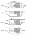
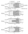
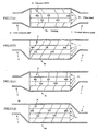
- the temperature is measured by changing a connecting relationship between the filter and the casing as shown in FIG. 12 .
- the temperature distribution appearing in the filter differs in accordance with the difference in the connecting position between the exhaust pipe and the casing as shown in FIG. 12 , and particularly the filter temperature tends to become high in the portion near to the exhaust pipe. Therefore, when conducting the temperature control of the filter, if it is intended to control the temperature to about 600°C well promoting the reaction of the catalyst, it is confirmed that a portion rendering into a high temperature exceeds 800°C. Also, as the construction of the catalyst itself is examined, it is confirmed that a noble metal used as the catalyst causes sintering (metal changes into large particles) immediately above 800°C and the reactivity becomes bad and the use thereof is impossible.
- the inventors have knowledge that when the ceramic filter is constituted with an aggregate of columnar filter units dividable in a radial direction as mentioned above, it is effective to carry different catalysts on the respective columnar filter units or change a carrying amount of the catalyst on the filter unit.
- That is a preferred embodiment of the invention as defined in claim 3 is a ceramic filter comprising an aggregate formed by combining a plurality of columnar filter units each having a honeycomb structure and made of porous ceramic sintered body through a sealing material layer (preferably a sealing material indicating an adhesiveness: adhesive layer) and integrally joining them, in which the aggregate is constituted by combining two or more kinds of the filter units wherein the filter units carry one or more kinds of catalysts.
- a sealing material layer preferably a sealing material indicating an adhesiveness: adhesive layer
- catalysts having different heat resistance or catalytic activities can be used as the different kinds of the catalyst.
- the filter unit carrying the catalyst is arranged in a portion having a slow gas flow rate or a small flow amount.
- the invention having the above construction has the function and effect as mentioned below. That is, in the invention, all of the filter unit fundamentally combined as the ceramic filter do not carry the same catalyst, but the different catalyst is carried every the filter unit, so that there can be provided a ceramic filter suitable for an exhaust gas purifying apparatus of an automobile causing a deflected gas flowing.
- an example of arranging catalysts having different heat resistances in accordance with positions in the radial direction of the filter or an example of carrying catalysts having different catalytic activities means that the catalyst most suitable in the use of the ceramic filter is selectively attached to the respective position.
- the filter carried with the catalyst having an excellent heat resistance is used in a portion having a fast flow rate or a large gas flow amount of the exhaust gas, whereby the catalyst in a position exposed to the high-temperature portion can be used over a long time.
- the regeneration can be efficiently conducted even in a portion of a relatively low temperature by using the filter carried with the catalyst having a large activity in the portion having a slow gas flow rate or a small gas flow amount.
- the filter unit having catalyst weight and density adjusted to a large level in a portion having a relatively low temperature it is possible to arrange the filter unit having catalyst weight and density adjusted to a small level in a portion having reversely a relatively high temperature.
- the aggregate of the ceramic filter can be formed by using both a filter unit carried with the catalyst and a filter unit not carried with the catalyst.
- the filter unit having no catalyst can be used in a portion promoting the regeneration of soot without the catalyst at a relatively high temperature, while the filter unit having the catalyst can be used in a portion requiring the catalyst effect at a relatively low temperature.
- the filter unit having the catalyst in a portion having a small flow amount of the exhaust gas and being relatively low in the temperature and reversely arrange the filter unit having no catalyst in a portion having a large flow amount of the exhaust gas and being relatively high in the temperature in the use of the ceramic filter.
- the ceramic filter having the above properties and interposed between the first and second exhaust pipes to form an exhaust gas purifying apparatus having a high strength and capable of using over a long time.
- a filter unit having a low strength arranged in a portion having a relatively fast flow rate and a filter unit having a high strength arranged in a portion having a relatively slow flow rate are integrally combined, whereby there can be provided a ceramic filter capable of coping with the temperature change generated when abnormal burning is caused due to unburnt soot in the portion having the slow flow rate.
- a ceramic filter having a high filtering efficiency, a low pressure loss and excellent heat resistance and thermal conductivity can be provided by using a porous silicon carbide sintered body as a material for the ceramic filter.
- the inventive exhaust gas purifying apparatus has a high strength and is capable of being used over a long time by interposing and arranging various ceramic filters having different properties in an axial direction and/or a radial direction in a casing between first and second exhaust pipes.
- An exhaust gas purifying apparatus 1 for a diesel engine as an embodiment of the invention and a ceramic filter used therefor are explained with reference to FIG. 1 to FIG. 13 below.
- the exhaust gas purifying apparatus 1 shown in FIG. 1 is an apparatus for purifying an exhaust gas discharged from a diesel engine 2 as an internal combustion engine.
- the diesel engine 2 comprises plural cylinders not shown, and each cylinder is connected to a branched part 4 of an exhaust manifold 3 made of a metallic material.
- Each branched part 4 is joined to a main body 5 of the manifold. Therefore, exhaust gas discharged from the each cylinder is collected to the manifold main body.
- first exhaust pipe 6 and a second exhaust pipe 7 each made of a metallic material.
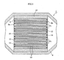
- An end portion of an upstream side of the first exhaust pipe 6 is connected to the manifold main body 5, and a cylindrical casing 8 made of a metallic material is arranged between the first exhaust pipe 6 and the second exhaust pipe 7. That is, an end portion of an upstream side of the casing 8 is connected to an end portion of a downstream side of the first exhaust pipe 6, and an end portion of a downstream side of the casing 8 is connected to an end portion of an upstream side of the second exhaust pipe 7.
- the casing 8 is arranged at an interposing state between the exhaust pipes 6, 7.
- a heat insulating material 10 is interposed between an outer peripheral face of the ceramic filter 9 and an inner peripheral face of the casing 8.
- the heat insulating material 10 is a matt containing ceramic fibers and has a thickness of 2 mm - 60 mm. It is desirable that the heat insulating material 10 has an elastic structure and a function of releasing heat stress.
- the heat insulating material prevents the escape of heat from the outermost peripheral portion of the filter 9, whereby energy loss in the regeneration can be suppressed to a minimum, and also since it has the elastic structure, the shifting of the position of the ceramic filter 9 due to the pressure of the exhaust gas and the vibration during the running can be prevented.
- a main application of the ceramic filter 9 is a diesel particulate filter (DPF) for removing diesel particulates in the exhaust gas discharged from the diesel engine.
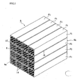
- a block 9 constituting the filter shown in FIG. 2 is formed by bundling a plurality of ceramic filter units F1 having a honeycomb structure so as to combine faces perpendicular to an axial direction with each other and integrally uniting them to form an aggregate (block).
- a filter unit F1 positioned in a central portion of the aggregate is quadratic prism-shaped, an outer size of which is 33 mm x 33 mm x 150 mm.
- quadratic prism-shaped filter units F1 are bundled in 4 rows and 4 columns, i.e. a total of 16 units to form a quadratic prism-shaped aggregate (ceramic filter) of honeycomb filter units as a whole.
- These filter units F1 are preferable to be made of a porous silicon carbide sintered body. Because, the silicon carbide sintered body is excellent in the heat resistance and thermal conductivity as compared with the other ceramics. Of course, sintered bodies of silicon nitride, sialon, alumina, cordierite, mullite and the like can be used as a sintered body other than silicon carbide. Further, as the unit F1 can be used a silicon-containing ceramic formed by compounding metallic silicon with the above ceramic, or a ceramic bonded with silicon or a silicate compound.
- each of these filter units F1 is provided with a honeycomb structure, so that there is an advantage that even when the catching amount of particulates increases, the pressure loss is small.
- each of the filter units F1 are regularly formed plural through-holes 12 having substantially a quadrate at section along an axial direction of the unit.
- the through-holes 12 are partitioned with each other through thin cell walls 13, and an oxidation catalyst consisting of an element of platinum group (e.g. Pt or the like) or the other metal element or an oxide thereof is carried on the cell wall 13.
- a catalyst purifying Ca, HC, Nox or the like may be carried, or a rare earth element, alkaline earth metal, alkali metal, transition metal may be carried.
- opening portions of each through-hole 12 are sealed with a plug 14 (porous silicon carbide sintered body in this embodiment) at either one of end faces 9a, 9b, and viewing the whole of the end faces 9a, 9b, the opening portions and the sealed portions are constructed so as to indicate a checkered pattern.
- a plug 14 porous silicon carbide sintered body in this embodiment
- the filter unit F1 is at a state of constituting with many cells having a quadratic form at section.
- a density of the cells is about 100-400 cells/inch square and a thickness of the cell wall 13 is about 0.05-0.5 mm.
- the cell structure is generally represented by dividing the thickness of the cell wall 13 as a unit of mil (1 mil is 0.0254 mm) by the cell density. That is, the above example is represented by 14/200. Therefore, about a half of many cells are opened at the upstream side end faces 9a, and the remaining half are opened at the downstream side end faces 9b.
- the average pore size is 1 ⁇ m - 50 ⁇ m, preferably about 5 ⁇ m - 20 ⁇ m.
- the average pore size is less than 1 ⁇ m, the clogging of the filter unit F1 due to the deposition of the particulates becomes conspicuous. While, when the average pore size exceeds 50 ⁇ m, fine particulates can not be caught and the filtering ability lowers.
- the porosity of the filter unit F1 is 30% - 80%, preferably 35% - 70%.
- the porosity is less than 30%, the unit becomes too dense and there is a fear that the exhaust gas can not be flown into the interior of the unit.
- the porosity exceeds 80%, the pores in the filter unit F1 becomes too large and there is a fear that the strength becomes weak and the catching efficiency of the particulates lowers.
- the sealing material layer 15 is preferable to have a thickness of about 0.3 mm - 3 mm, further preferably 0.5 mm - 2 mm. When the thickness is exceeds 3 mm, even if the thermal conductivity is high, the sealing material layer 15 is still a large heat resistor and hence the thermal conduction between the filter units F1 is obstructed. Also, a ratio of the filter unit F1 portion occupied in the ceramic filter 9 is relatively decreased to bring about the lowering of the filtering ability. Inversely, when the thickness of the sealing material layer 15 is less than 0.3 mm, the large heat resistor is not formed, but the adhesion property between the filter units F1 is lacking and the ceramic filter 9 is easily broken.
- the sealing material layer 15 is made of, for example, inorganic fibers, an inorganic binder, an organic binder and inorganic particles, and is desirable to be made of an elastic material formed by binding three-dimensionally crossed inorganic fibers and inorganic particles through the inorganic binder and organic binder.
- the inorganic fiber may be used one or more ceramic fibers selected from silica-alumina fibers, mullite fibers, alumina fibers and silica fibers. Among them, the use of the silica-alumina ceramic fibers is desirable. Because, the silica-alumina ceramic fiber is excellent in the elasticity and has an action of absorbing heat stress.
- the content of the silica-alumina ceramic fibers occupied in the sealing material layer 15 is 10% by weight - 70% by weight, preferably 10% by weight - 40% by weight, more preferably 20% by weight - 30% by weight as a solid content.
- the content is less than 10% by weight, the function and effect as the elastic body lower. While, when the content exceeds 70% by weight, not only the thermal conductivity but also the elasticity lower.
- the silica-alumina ceramic fiber is preferable to contain shots of 1% by weight - 10% by weight, preferably 1% by weight - 5% by weight, more preferably 1% by weight - 3% by weight.
- shots of 1% by weight - 10% by weight preferably 1% by weight - 5% by weight, more preferably 1% by weight - 3% by weight.
- the silica-alumina ceramic fiber has a fiber length of 1 mm - 100 mm, preferably 1 mm - 50 mm, more preferably 1 mm - 20 mm.
- the fiber length is less than 1 mm, the elastic structural body can not be formed, while when the fiber length exceeds 100 mm, the fibers are pilled and the dispersibility of the inorganic particles is deteriorated, and further it is difficult to thin the sealing material layer 15 to not more than 3 mm and hence it is not attempted to improve the thermal conduction between the filter units F1.
- the inorganic binder included in the sealing material layer 15 is desirable at least one colloidal sol selected from silica sol and alumina sol. Particularly, it is desirable to select the silica sol. Because, the silica sol is available and easily changes into SiO 2 through firing and is suitable as an adhesive at a high temperature region. Also, the silica sol is excellent in the insulating property.
- the content of the silica sol in the sealing material layer 15 is 1% by weight - 30% by weight, preferably 1% by weight - 15% by weight, more preferably 5% by weight - 9% by weight as a solid content.
- the content is less than 1% by weight, the adhesion strength lowers, while when the content exceeds 30% by weight, the thermal conductivity largely lowers.
- a hydrophilic organic high polymer is preferable, and at least one polysaccharide selected from polyvinyl alcohol, methylcellulose, ethylcellulose and carboxymethyl cellulose is more preferable. Among them, it is desirable to select carboxymethyl cellulose. Because, carboxymethyl cellulose gives a preferable fluidity to the sealing material layer and indicates an excellent adhesiveness at a room temperature region.
- the content of the carboxymethyl cellulose in the adhesive layer is 0.1% by weight - 5.0% by weight, preferably 0.2% by weight - 1.0% by weight, more preferably 0.4% by weight - 0.6% by weight as a solid content. When the content is less than 0.1% by weight, migration can not be sufficiently controlled.
- the term "migration" used herein means a phenomenon that in case of curing the sealing material layer filled between bodies to be adhered, the binder moves accompanied with the removal of the solvent through drying. While, when the content exceeds 5.0% by weight, the organic binder burns out at a higher temperature and the strength of the sealing material layer 15 lowers.
- the inorganic particles included in the sealing material layer 15 is preferable an elastic material using one or more inorganic powder or whisker selected from silicon carbide, silicon nitride and boron nitride.
- silicon carbide, silicon nitride and boron nitride are very large in the thermal conductivity and contribute to improve the thermal conduction owing to the inclusion on a surface of the ceramic fiber or a surface of the colloidal sol and interiors thereof.
- the inorganic powder of the carbide and nitride it is desirable to select silicon carbide powder. Because, silicon carbide is very high in the thermal conductivity and has a property of being easily familiar with the ceramic fiber. Further, the filter unit F1 as a body to be adhered is the same kind, i.e. porous silicon carbide in this embodiment.
- the content of silicon carbide powder is 3% by weight - 80% by weight, preferably 10% by weight - 60% by weight, more preferably 20% by weight - 40% by weight as a solid content.
- the content is less than 3% by weight, the thermal conductivity of the sealing material layer 15 lowers and hence the sealing material layer 15 becomes still a large heat resistor. While, when the content exceeds 80% by weight, the adhesion strength at high temperatures lowers.
- the particle size is 0.01 ⁇ m - 100 ⁇ m, preferably 0.1 ⁇ m - 15 ⁇ m, more preferably 0.1 ⁇ m - 10 ⁇ m.
- the particle size exceeds 100 ⁇ m, the adhesion force and thermal conductivity lower, while when the particle size is less than 0.01 ⁇ m, the cost of the sealing material layer 15 increases.
- the exhaust gas is fed from a side of the upstream side end face 9a. That is, the exhaust gas flown from the first exhaust pipe 6 first flows into the cell opening to the upstream side end face 9a of the ceramic filter. Then, the exhaust gas passes through the cell wall 13 and flows into the adjoining other cell (i.e. adjoining cell at a side opening to the downstream side end face 9b), which is discharged from the opening downstream side end face 9b. In such a flowing of the gas, particulates included in the exhaust gas (diesel particulate) can not pass through the cell wall 13, so that they are trapped on the surface of the cell wall 13 as they are. As a result, the purified exhaust gas is discharged from the downstream side end face 9b of each filter unit F1. Then, the purified exhaust gas passes through the second exhaust pipe 7 and is finally discharged into air.
- the particulates trapped by the cell wall 13 are burnt out by the action of the catalyst when the internal temperature of the ceramic filter 9 reaches to a given temperature.
- the pressure loss property when the exhaust gas passes through the cell wall 13 is considered as follows.
- the pressure loss when the diesel exhaust gas passes through the filter unit F1 can be shown in FIG. 4 .
- ⁇ P4 is a resistance when the diesel particulates pass through the cell wall 13 of the filter unit F1 after the deposition, which is a value corresponding to 2-3 times or more of the initial pressure loss.
- filter units F1 cell wall thickness, porosity, pore size, cell structure
- the filter unit F1 having a large pressure loss is arranged in a portion having a fast gas flow rate and the filter unit F1 having a small pressure loss is arranged in a portion having a slow gas flow rate, and they are integrally combined. Concrete examples thereof are mentioned as follows.
- filter units having different strengths are used as different kinds of filter units F1.
- a filter unit having a small strength is arranged in the portion having a fast gas flow rate and a filter unit having a high strength is arranged in the portion having a slow gas flow rate in accordance with the invention.
- the catalyst used is preferable to be a rare earth oxide-containing alumina film 17 separately coating the surface of each SiC particle 16 with respect to SiC particles 16 of SiC sintered body constituting the cell walls 13 partitioning each cell of the filter unit F1.
- alumina has a high specific surface area and is suitable as a catalyst carrying film. Particularly, it is desirable to develop filter units F1 stably acting at a higher temperature and having a high heat resistance at the present time, and the alumina film 17 is required to have a higher heat resistance accompanied therewith.
- the shape of each alumina particle is rendered into a small fiber and 2 a rare earth oxide such as ceria (cerium oxide) or the like is included therein.
- a rare earth oxide such as ceria (cerium oxide) or the like.
- the alumina film 17 covering the surface of each SiC particle in the filter unit F1 shows a hair implant structure that alumina particles stand up in form of small fibers at a microscopic section.
- the heat resistance is considerably improved because the contact points between adjoining alumina small fibers is reduced.
- the heat resistance is improved by adding ceria or the like. This is due to the fact that a new compound is formed on the surfaces of the crystal particles constituting the alumina film 17 to obstruct the growth of alumina particles.
- SiC or SiO 2 existing on an extreme surface layer thereof feeds Si in the heat treatment to shut off a mass transfer course, whereby the heat resistance is improved. According to the inventors' studies, it is confirmed that when SiC is intentionally treated at a high temperature to form an oxide, the heat resistance is further improved.
- the regeneration property of the alumina film 17 is described below.
- the alumina film 17 is obtained by adding a rare earth oxide such as ceria (CeO 2 ) or lanthana (La 2 O 3 ) in an amount of about 10-80 mass%, preferably 20-40 mass% based on Al 2 O 3 and uniformly dispersing the oxide into the surface or interior of the alumina film 17.
- a rare earth oxide such as ceria (CeO 2 ) or lanthana (La 2 O 3 )
- the feeding of oxygen into the exhaust gas is activated by an action of adjusting oxygen concentration inherent to ceria, whereby the efficiency of burning and removing "soot (diesel particulates) adhered to the filter unit F1 is improved and hence the regeneration ratio of the filter unit F1 is considerably improved. Also, the durability of the filter unit F1 can be improved.
- the rare earth oxide such as ceria or the like improves the heat resistance of alumina but also plays a role of adjusting the oxygen concentration on the surface of the filter unit F1.
- hydrocarbon or carbon monooxide existing in the exhaust gas is removed by oxidation reaction and NOx is removed by reducing reaction.
- Ceria added to the catalyst is relatively low in the redox potential of Ce 3+ and Ce 4+ and reversibly promotes a reaction of 2CeO 2 ⁇ -> Ce 2 O 3 + 1/2O 2 . That is, when the exhaust gas renders into a rich region, the above reaction proceeds to the right to feed oxygen into an atmosphere, while when it renders into a lean region, the reaction proceeds to the left to occlude extra oxygen in the atmosphere.
- the ceria adjusts the oxygen concentration in the atmosphere and takes an action of widening a width of an air-fuel ratio so as to efficiently remove hydrocarbon, carbon monooxide or NOx.
- the catalyst containing no CeO 2 oxidizes soot by activating oxygen in the exhaust gas. This reaction is poor in the efficiency because oxygen in the fluid should be activated.
- the catalyst containing CeO 2 feeds oxygen by the following reaction formula: CeO 2 ⁇ CeO 2-x + x/2O 2 That is, oxygen discharged into the atmosphere and oxygen in the exhaust gas are activated by the catalyst (noble metal) and reacted with soot (carbon) to form CO 2 (CeO 2-x is oxidized to original CeO 2 ). Also, CeO 2 and soot directly contact with each other, so that even if the oxygen amount discharged is small, the soot can be efficiently oxidized.
- CeO 2 increases OSC (oxygen storing capacity) owing to the carrying of the catalyst (noble metal). Because, the catalyst (noble metal) activates oxygen in the exhaust gas and activates oxygen on the surface of CeO 2 near to noble metal, and the OSC is increased.
- the rare earth oxide it is preferable to use a composite oxide of rare earth element and zirconium in addition to the above single oxide (CeO 2 ). In this case, it is considered that when zirconium oxide is included in the rare earth oxide, the grain growth of the rare earth oxide is suppressed to improve the controlling property of oxygen concentration.
- the particle size is preferably about 1-30 nm, more preferably 2-20 nm.
- the particle size is less than 1 nm, it is difficult to produce the composite oxide.
- the particle size exceeds 30 nm, the particles easily cause the sintering and hence the surface area of the particles becomes small and the contact area with the exhaust gas becomes small and there is a problem that the activity is weak. Further, there is feared that the pressure loss in the pass of the exhaust gas becomes large.
- a noble metal or an element selected from elements of Group VIa and VIII in the Periodic Table as a catalyst.
- an element are concretely mentioned platinum (Pt), palladium (Pd), rhodium (Rh), nickel (Ni), cobalt (Co), molybdenum (Mo), tungsten (W), cerium (Ce), copper (Cu), vanadium (V), iron (Fe), gold (Au), silver (Ag) and the like.
- At least one element selected from Pt, Au, Ag and Cu as a noble metal, Mo, W as an element of Group VIa, Fe, Co, Pd, Rh, Ni as an element of Group VIII and V, Ce as an element other the above in the Periodic Table or a compound thereof may be carried on the alumina film 17.
- a binary alloy or a ternary alloy based on a combination of the above elements is used as the compound. It is advantageous to use such an alloy together with the rare earth oxide such as ceria, lanthana or the like acting as a co-catalyst as mentioned above.
- the thus formed filter unit F1 is less in the deterioration due to poisoning (lead poisoning, phosphorus poisoning, sulfur poisoning) and small in the thermal deterioration and excellent in the durability.
- compounds based on a combination with the other element may be used in addition to the alloy of the above combination.
- the binary alloy includes Pt/Pd, Pt/Rh, Pt/Ni, Pt/Co, Pt/Mo, Pt/W, Pt/Ce, Pt/Cu, Pt/V, Pt/Fe, Pt/Au, Pt/Ag, Pd/Rh, Pd/Ni, Pd/Co, Pd/Mo/ Pd/W, Pd/Ce, Pd/Cu, Pd/V, Pd/Fe, Pd/Au, Pd/Ag, Rh/Ni, Rh/Co, Rh/Mo, Rh/W, Rh/Ce, Rh/Cu, Rh/V, Rh/Fe, Rh/Au, Rh/Ag, Ni/Co, Ni/Mo, Ni/W, Ni/Ce, Ni/Cu, Ni/V, Ni/Fe, Ni/Au, Co/Mo, Co/W, Co/Ce, Co/Cu, Co/V, Co/Fe, Co/AAg, Co/Mo,
- the ternary alloy there are Pt/Pd/Rh, Pt/Pd/Ni, Pt/Pd/Co, Pt/Pd/Mo, Pt/Pd/W, Pt/Pd/Ce, Pt/Pd/Cu, Pt/Pd/V, Pt/Pd/Fe, Pt/Pd/Au, Pt/Pd/Ag, Pt/Rh/Ni, Pt/Rh/Co, Pt/Rh/Mo, Pt/Rh/W, Pt/Rh/Ce, Pt/Rh/Cu, Pt/Rh/V, Pt/Rh/Fe, Pt/Rh/Au, Pt/Rh/Ag, Pt/Ni/Co, Pt/Ni/Mo, Pt/Ni/W, Pt/Ni/Ce, Pt/Ni/Cu, Pt/Ni/V, Pt/Ni/Fe, Pt/Ni/Cu
- an impregnation method, an evaporation drying method, an equilibrium adsorption method, incipient wetness method or a spraying method is advantageously applicable.
- the incipient wetness method is advantageous.
- This method is a method wherein an aqueous solution containing a given amount of the catalyst is added dropwise to the filter unit F1 and the impregnation of the catalyst into pores of the filter unit F1 is stopped at a time of uniformly and slightly wetting the surface of the carrier (incipient state) and thereafter the drying and firing are conducted. That is, the dropwise addition of the catalyst-containing solution on the surface of the filter unit F1 is carried out by using a bullet or an injection syringe.
- the carrying amount of catalyst can be controlled by adjusting the concentration of the solution.
- a feature of the method of carrying the catalyst on the filter unit F1 in this embodiment lies in that the alumina film 17 containing the rare earth oxide is formed on the irregular surface of the filter unit F1 by a sol-gel process. Particularly, the alumina film 17 containing the rare earth oxide is coated onto each surface of SiC particles forming the cell wall 13 through the impregnation of the solution. Then, the alumina film 17 is changed into an alumina film (carrier film) 17 showing a hair implant structure that ceria-dispersed alumina stands up in form of small fibers at a microscopic section through a step of treated with hot water after the calcining, and then a given amount of the catalyst is adsorbed and fixed onto the surface of the alumina film 17.
- oxidation is carried out by heating at 800-1600°C for 5-100 hours in order to feed a required amount of Si promoting a chemical bonding with alumina on each surface of SiC particles 16. If sufficient oxide film is existent on the surface of SiC particles 16, this step may be naturally omitted.
- SiC sintered body itself contains about 0.8 mass% of SiO 2 .
- the temperature is lower than 800°C, the oxidation reaction hardly occurs, while when it exceeds 1600°C, the oxidation reaction extremely proceeds and the lowering of the strength in the filter is caused.
- a recommendable condition is 1000-1500°C and 5-20 hours. In this condition, SiO 2 enough to feed Si can be formed on the surface, and also the porosity and pore size in the filter unit F1 are not changed and the pressure loss property is not damaged.
- a treatment coating the rare earth oxide containing alumina film 17 is carried out by impregnating each surface of the SiC particles 16 constituting the cell wall 13 with a solution of a metal compound containing aluminum and rare earth element, e.g. a mixed aqueous solution of aluminum nitrate and cerium nitrate or the like through a sol-gel process.
- a metal compound containing aluminum and rare earth element e.g. a mixed aqueous solution of aluminum nitrate and cerium nitrate or the like through a sol-gel process.
- a metal inorganic compound and a metal organic compound As a starting metal compound are used a metal inorganic compound and a metal organic compound.
- the metal inorganic compound are used Al(NO 3 ) 3 , AlCl 3 , AlOCl, AlPO 4 , Al 2 (SO 4 ) 3 , Al 2 O 3 , Al(OH) 3 , Al and the like.
- Al(NO 3 ) 3 and AlCl 3 are preferable because they are easily soluble in alcohol, water or the like and are easy in the handling.
- the metal organic compound are mentioned a metal alkoxide, a metal acetylacetonate and a metal carboxylate.
- cerium-containing solution in the above mixed aqueous solution are used Ce(NO 3 ) 3 , CeCl 3 , Ce 2 (SO 4 ) 3 , CeO 2 , Ce(OH) 3 , Ce 2 (CO 3 ) 3 and the like.
- a solvent in the above mixed solution is used at least one selected from water, alcohol, diol, polyvalent alcohol, ethylene glycol, ethylene oxide, triethanolamine, xylene and the like.
- hydrochloric acid, sulfuric acid, nitric acid, acetic acid or fluoric acid may be added as a catalyst.
- at least one element selected from Ce, Li, K, Ca, Sr, Ba, La, Pr, Nd, Si and Zr or a compound thereof other than oxide (nitrate, chloride, sulfate, hydroxide or carbonate) may be added to the starting material in addition to the rare earth oxide.
- a preferable metal compound in this embodiment mention may be made of Al(NO 3 ) 3 and Ce(NO 3 ) 3 . They are dissolved in the solvent at a relatively low temperature and is easy in the preparation of the starting solution. Also, 1,3-butane diol is recommended as a preferable solvent. A first reason of the recommendation lies in that the viscosity is adequate and a gel film having a proper thickness may be formed on the SiC particles 16 at a gel state. A second reason is due to the fcat that this solvent forms a metal alkoxide in the solution and a metal oxide polymer having oxygen-metal-oxygen bond or a precursor of metal oxide gel may be easily formed.
- the amount of Al(NO 3 ) 3 is desirable to be 10-50 mass%. When it is less than 10 mass%, the alumina amount having a surface area for maintaining the activity of the catalyst for a long time can not be carried, while when it exceeds 50 mass%, an amount of heat generation becomes large in the dissolution and the gelation is easily caused.
- the amount of Ce(NO 3 ) 3 is preferable to be 1-30 mass%. When it is less than 1 mass%, the oxidation of the soot can not be promoted, while when it exceeds 30 mass%, the grain growth of CeO 2 occurs after the firing.
- the mixing ratio of Al(NO 3 ) 3 to Ce(NO 3 ) 3 is preferable to be 10:2. As Al(NO 3 ) 3 becomes richer, the dispersibility of CeO 2 particles after the firing can be improved.
- the temperature is desirable to be 50-130°C.
- the solubility of the solute is low, while when it exceeds 130°C, the reaction is violently promoted to cause gelation and the use of the applying solution is impossible.
- the stirring time is desirable to be 1-9 hours. When it is within the above range, the viscosity of the solution is stable.
- ZrO(NO 3 ) 2 or ZrO 2 is used as a zirconium source for producing a composite oxide with zirconium or a solid solution in addition to the above example.
- the above substance is dissolved in water or ethylene glycol to form a mixed solution and dried and fired to form the above composite oxide.
- the solution of the above metal compound is sufficiently penetrated into all pores between SiC particles 16 in the cell wall 13.
- the deaeration apparatus may be used a vacuum pump or the like in addition to an aspirator. By using such an apparatus can be removed air from the pores in the cell wall 13 and hence the solution of the metal compound can be well fed onto the each surface of SiC particles 16.
- This step is a treatment that volatile components such as NO 2 and the like are removed by evaporation and the solution is gelated and fixed to the surfaces of SiC particles 16 and at the same time extra solution is removed, which is carried out by heating at 120-170°C for about 2 hours.
- the heating temperature is lower than 120°C, the volatile components hardly evaporate, while when it exceeds 170°C, the gelated film thickness become nonuniform.
- This step is a calcining treatment for removing residual components to form an amorphous alumina film 17. Concretely, it is desirable to heat at a temperature of 300-500°C. When the calcining temperature is lower than 300°C, the residual organic mass is hardly removed, while when it exceeds 500°C, Al 2 O 3 is crystallized and hence boehmite of small fibrous protrusion can not be formed.
- This step is a treatment that the calcined filter unit F1 is immersed in hot water for forming the alumina film 17 having a specified structure inherent to the above embodiment.
- the particles on the surface of the amorphous alumina film 17 is immediately discharged into the solution at a sol state by a deflocculation action and also boehmite particles produced by hydration are aggregated in form of small fibrous protrusions and form a stable state against deflocculation.
- the rare earth oxide-containing alumina adhered to each surface of the SiC particles 16 is stood up in form of small fibers (protrusions) by the hot water treatment, which forms a rough surface indicating the hair implant structure. Therefore, there is formed the alumina film 17 having a high specific surface area.
- the sintering of alumina mainly proceeds through surface diffusion, and when it is changed into ⁇ -alumina phase, the specific surface area rapidly reduces.
- silica is enclosed in the alumina particles, it is considered that hole sites of alumina are clogged with silica in the course of the heat treatment or silica moves toward surfaces of needle-like particles to control the surface diffusion or the sintering of the particles.
- the temperature is desirable to be 50-100°C.
- the hydration of the amorphous alumina film 17 does not proceed and the boehmite of small fibrous protrusion is not formed.
- water is evaporated and this step is hardly maintained over a long time.
- the treating time is desirable to be not less than 1 hour. When it is less than 1 hour, the hydration of the amorphous alumina is insufficient.
- a treatment for dehydrating boehmite produced through hydration to form alumina crystal is conducted.
- the firing temperature is preferable to be 500-1000°C. When the temperature is lower than 500°C, the crystallization does not proceed, while when it exceeds 1000°C, the sintering proceeds much and there is a tendency of lowering the surface area.
- the carrying amount of the catalyst is determined by adding dropwise and impregnating the aqueous solution containing Pt or the like by a water absorbing amount of the filter unit F1 so as to slightly wet the surface thereof.
- the water absorbing amount held by the filter unit F1 means that when the measured value of the water absorbing amount of a dry carrier is 22.46 mass%, if the carrier has a mass of 110 g and a volume of 0.1631, the carrier absorbs 24.79/1 of water.
- a starting material of Pt for example, a solution of dinitrodiamine platinum nitrate ([Pt(NH 3 ) 2 (NO 2 ) 2 ]HNO 3 , Pt concentration: 4.53 mass%).
- the aqueous solution of dinitrodiamine platinum nitrate adjusted to a given amount as mentioned above is added dropwise to both end faces of the filter unit F1 at constant intervals through a pipette. For example, 40-80 droplets are added every one-side face at constant intervals, whereby Pt is uniformly dispersed and fixed onto the surface of the alumina thin film 3 covering the filter unit F1.
- the filter unit F1 is used as a diesel particulate filter (hereinafter abbreviated as DPF simply). This unit itself has only a function of catching particulates (floating particular substance: PM) with the cell wall 13, but when the catalyst is carried thereon, hydrocarbon and carbon monooxide in the exhaust gas can be oxdized.
- DPF diesel particulate filter
- the filter unit F1 is preferable to apply to a system for particularly treating a diesel exhaust gas, whereby the following functions can be expected:
- the thus obtained ceramic filter 9 is wound with a heat insulating material 10, and then the ceramic filter 9 is placed in a casing 8 at this state, and a first exhaust pipe 6, the casing 8 and a second exhaust pipe 7 are arranged in this order.
- casings 8a-8d having four kinds of pipe arrangements as shown in FIG. 5 is fed an exhaust gas from a diesel engine for a constant time. After the catching for 10 hours, the ceramic filter 9 is taken out and cut to observe visually.
- soot 16 is stored in the each kind of the casings 8a, 8b, 8c and 8d as shown in FIG. 5 .
- the first exhaust pipe 6 and the second exhaust pipe 7 are arranged in a central portion of the casing 8 at section, so that a greater part of the soot 16 is stored in the central portion of the ceramic filter 9.
- the first exhaust pipe 6 and the second exhaust pipe 7 are arranged on either one side of the peripheral edge portion of the casing 8, so that a greater part of the soot 16 is stored on an elongated line of the exhaust pipe toward the peripheral edge portion of the ceramic filter 9 at section.
- the first exhaust pipe 6 is arranged in the central portion of the casing 8 at section, while the second exhaust pipe 7 is arranged in the peripheral edge portion of the casing 8 at section, so that a greater part of the soot is stored in the central portion of the ceramic filter 9 and the peripheral edge portion arranging the second exhaust pipe.
- the first exhaust pipe 6 is positioned in an upper peripheral portion of the casing 8, while the second exhaust pipe 7 is positioned in a lower peripheral portion of the casing 8 and is not opposed to the first exhaust pipe 6, so that a greater part of the soot 16 is stored in portions of the ceramic filter 9 corresponding to the arranged positions of the first exhaust pipe 6 and the second exhaust pipe 7.
- the storing amount of the soot 16 is proportional to a flowing amount of a gas.
- the filter unit F1 positioned near to the downstream side end of the first exhaust pipe is faster in the incoming gas rate as compared with the filter unit F1 located far away therefrom (the amount is larger), and also if the upstream side end of the second exhaust pipe is located opposite to the same filter, the gas rate in the filter at this position more increases (the amount becomes larger).
- the first exhaust pipe and the second exhaust pipe are connected to the central portion of the casing as shown in FIG. 5(a) .
- the ceramic filter 9 therefore, there can be another region producing the difference of the flow rate between the central portion of 4 units and the peripheral portion of 12 units.
- comparative tests are carried out by applying various kinds of filters to the two regions.
- Example 1-1 the ceramic filter 9 is basically prepared in the same manner as in the reference example.
- Two kinds of SiC filters having different strengths are used in Example 1-1 as shown in Table 1.
- a higher firing temperature is set to 2300°C - 3 hr
- a lower firing temperature is set to 2100°C - 2 hr.
- the strength is measured by a three-point bending test described in JIS R1625. In this case, a lower spun is set to 135 mm, and a head speed is set to 0.5 mm/sec. This test is carried out 20 times, and the ceramic filter 9 is prepared by selecting filters from the same production lot.
- the ceramic filter 9 is prepared by setting 12 SiC filters having an average bending load of 250 kg/cm 2 to the peripheral portion and 4 SiC filters having an average bending load of 350 kg/cm 2 to the central portion.
- the thus obtained ceramic filter 9 is wound with a heat insulating material 10 and received in a casing 8, and an exhaust gas of an engine is fed for a given time as shown in the reference example. After the catching for 10 hours, the filter is taken out and cut to conduct visual observation. As a result, the storing amount in the peripheral portion of the filter becomes smaller than that in the central portion as shown in FIG. 6(a) .
- the ceramic filter 9 is basically prepared in the same manner as in the reference example.
- the ceramic filter 9 is prepared by using 16 SiC filters having a standard average bending load of 250 kg/cm 2 as shown in Table 5.
- the ceramic filter 9 is prepared by using 4 SiC filter having an average bending load of 250 kg/cm 2 in the central portion and 12 SiC filters having a standard average bending load of 350 kg/cm 2 in the peripheral portion.
- the thus obtained ceramic filter 9 is wound with a heat insulating material 10 and received in a casing 8, and an exhaust gas of an engine is fed for a given time as shown in the reference example. After the catching for 10 hours, the filter is taken out and cut to conduct visual observation. As a result, even in Comparative Examples 1-1, 1-2, the storing amount in the peripheral portion becomes smaller than that in the central portion as shown in FIG. 6(a) .
- Example 1-1 Comparative Example 1-1 Comparative Example 1-2 Central portion Peripheral portion Central Portion Peripheral portion Central Portion Peripheral portion Filter unit SiC SiC SiC SiC SiC Cell structure (mill/cell number) 14/200 14/200 14/200 14/200 14/300 14/200 Porosity of filter 42% 42% 42% 42% 42% 42% Pore size of filter 10 ⁇ m 10 ⁇ m 10 ⁇ m 10 ⁇ m 10 ⁇ m 10 ⁇ m Pressure loss (PM0g/L,13m/s) 10 10 10 10 10 10 10 10 10 10 10 Average bending load 350 kgf/cm2 250 kgf/cm 2 250 kgf/cm 2 250 kgf/cm 2 250 kgf/cm 2 250 kgf/cm 2 350 kgf/cm 2 Regeneration ratio 90% 85% 88%
- the catching and regeneration are repeated by utilizing an engine having a slow gas flow rate in the regeneration.
- Example 2-1 is an example that a ceramic filter 9 is basically prepared in the same manner as in Example 1. In Example 2-1, however, the ceramic filter 9 is prepared by using two kinds of SiC filters having different strengths as shown in Table 2.
- the thus obtained ceramic filter 9 is wound with a heat insulating material 10 and received in a casing 8, and an exhaust gas of an engine is fed for a given time as shown in the reference example. After the catching for 10 hours, the ceramic filter 9 is taken out and cut to conduct visual observation. As a result, the storing amount in the peripheral portion becomes smaller than that in the central portion as shown in FIG. 6(a) .
- the ceramic filter 9 is basically prepared in the same manner as in the reference example.
- the ceramic filter 9 is prepared by using 16 SiC filters having a standard average bending load of 250 kg/cm 2 as shown in Table 6.
- the ceramic filter 9 is prepared by using 4 SiC filters having an average bending load of 250 kg/cm 2 in the central portion and 12 SiC filters having a standard average bending load of 350 kg/cm 2 in the peripheral portion.
- the thus obtained ceramic filter 9 is wound with a heat insulating material 10 and received in a casing 8, and an exhaust gas of an engine is fed for a given time as shown in the reference example. After the catching for 10 hours, the filter is taken out and cut to conduct visual observation. As a result, even in Comparative Examples 2-1, 2-2, the storing amount in the peripheral portion becomes smaller than that in the central portion as shown in FIG. 6(a) .
- Example 2-1 Comparative Example 2-1 Comparative Example 2-2 Central portion Peripheral portion Central portion Peripheral portion Central portion Peripheral portion Filter unit SiC SiC SiC SiC SiC Cell structure (mill/cell number) 14/300 14/200 14/200 14/200 14/200 14/200 14/200 Porosity of filter 42% 42% 42% 42% 42% 42% Pore size of filter 10 ⁇ m 10 ⁇ m 10 ⁇ m 10 ⁇ m 10 ⁇ m 10 ⁇ m 10 ⁇ m Pressure loss (PM0g/L,13m/s) 10 10 10 10 10 10 10 10 10 10 10 10 10 10 10 Average bending load 250 kgf/cm 2 350 kgf/cm 2 250 kgf/cm 2 250 kgf/cm 2 350 kgf/cm 2 250 kgf/cm 2 350 kgf/cm 2 250 kgf/cm 2 Regeneration ratio 85% 85% 88%
- filters suitable for the catching amount can be set by using filters having
- the above embodiments of the invention may be changed as follows. That is, heat is applied to the ceramic filter (aggregate) by the exhaust gas in these embodiments, but the same exhaust gas purifying apparatus can be applied to the portion of regenerating the filter by means of a heating means such as a heater or the like.
- a great amount of the catalyst may be adhered to the wall or may be penetrated into the interior.
- the ceramic filter according to the invention is excellent in the strength and is excellent in the action of uniformly catching soot and uniformly conducting the regeneration, so that it can be used in the exhaust gas purifying apparatus for an automobile.
- the invention can be utilized in an exhaust gas purifying apparatus of a diesel engine.
Abstract
Description
- This invention relates to an exhaust gas purifying apparatus according to the preamble of
claim 1. Such an apparatus is known fromEP1174399A1 . - Recently, the number of automobiles is exponentially increasing, and an amount of exhaust gas discharged from an internal engine of the automobile rapidly goes on increasing. Particularly, various substances including in the exhaust gas discharged from a diesel engine are a cause raising air pollution and give a serious influence upon natural environment. Also, there are lately reported study results that particulates in the exhaust gas (diesel particulate) are a cause raising an allergic obstacle and a reduction of spermatozoon number, so that it is an urgent issue for humans to take a countermeasure for removing the particulates in the exhaust gas.
- Under such a situation, there have hitherto been proposed various apparatuses for the purification of the exhaust gas. As the general apparatus for the purification of the exhaust gas, there is, for example, a structure that a casing is arranged on the way of an exhaust pipe connected to an exhaust manifold of an engine and a filter having fine holes is arranged therein. As a material constituting the filter, there are metals, alloys and ceramics. As a typical example of the filter made of the ceramic is well-known a cordierite filter. Recently, porous silicon carbide sintered body having such merits that the heat resistance, mechanical strength and catching efficiency are high, and the chemical stability is good, and the pressure loss is low and the like is used as an example of a filter-forming material.
- The general ceramic filter and the exhaust gas purification apparatus using the same are such constructed that when the exhaust gas passes through many cells formed along an axial direction of the filter, fine particles in the exhaust gas are trapped in the cell walls to remove the fine particles from the exhaust gas. However, a ceramic filter made of a porous silicon carbide sintered body is generally large in the thermal expansion and weak to thermal shock, so that there is a problem that as the size becomes larger, crack is apt to be easily produced. In this connection,
JP-A-8-28246 - Moreover, the ceramic filter is preferable to be wound on its outer peripheral face with a matt-shaped heat insulating material such as ceramic fibers or the like, and is received in a casing disposed on the way of an exhaust pipe of an automobile or the like at such a state.
- In such a filter, as the catching and burning (regeneration) of soot are repeated, there may be caused the scattering of the catching amount of soot in accordance with the position of the ceramic filter.
- On the other hand,
JP-A-1-145377 - The above conventional technique (
JP-A-1-145377 - Also, when the aforementioned conventional ceramic filter is used by repeatedly conducting the regeneration over a constant period as a whole, as seen from a graph of a regenerating ratio (a ratio of changing weight before and after the regeneration) shown in
FIG. 13 , it is confirmed that the soot is surely burnt at an initial stage, but the reactivity as a catalyst is gradually lowered as the regeneration is repeated several times. - In the light of the above problems included in the conventional techniques, it is an object of the invention to provide a ceramic filter in which soot can be equally caught in axial and radial directions of the filter as a whole and it is effective to uniformly conduct the regeneration and the high efficiency of removing the exhaust gas (filter efficiency) can be maintained over a long time and further the durability is excellent.
- It is another object of the invention to provide an apparatus for the purification of the exhaust gas using the above ceramic filter having a high filter efficiency and excellent strength and service life.
- The inventors have made studies for achieving the above objects and confirmed that the difference in the filter efficiency and the regeneration efficiency is caused dependent upon an arranging place of the ceramic filter. That is, it is confirmed that there is a large difference in the flow amount and the flow rate between a near side and far side of the filter to the exhaust pipe. In general, a
casing 8 located downstream side an exhaust manifold of a diesel engine as an internal combustion engine is formed so as to make a diameter of its central section larger than those of a first exhaust pipe and a second exhaust pipe, and the ceramic filter is received in the casing. In case of such a ceramic filter, the gas flow amount is larger in the filter located at a position near to a downstream side end portion of the first exhaust pipe than that in the filter located at a far position (flow rate is faster), and particularly when the second exhaust pipe is located at an opposite side (lower end side), the gas flow amount and the flow rate are more increased. - In this structure, the first exhaust pipe and the second exhaust pipe are connected so as to position at upstream side and downstream side sandwiching the casing, so that the flow amount of the central portion of the ceramic filter becomes large (flow rate is fast) and the flow amount of the peripheral portion thereof is small (flow rate is slow). As a result, the central portion of the filter is largely affected by the gas flown thereinto rather than the peripheral portion thereof. In the invention, therefore, different properties are given to each part in the axial direction of the ceramic filter (gas flowing direction) or a radial direction perpendicular thereto, for example, different kinds of filter units dividing into the central portion having a fast flow rate and the peripheral portion having a slow flow rate are properly combined to form a ceramic filter, whereby there can be obtained the ceramic filter capable of conducting uniform catching and regeneration over a whole of the filter.
- The invention is developed under the above idea, and comprises a ceramic filter having such a construction that different properties are applied to a filter made of porous ceramic sintered body having a honeycomb structure every part in a gas flowing direction (axial direction) and/or a radial direction perpendicular thereto.
- Particularly, the afore-mentioned objects are solved by an exhaust gas purifying apparatus as defined in
claim 1. Preferred embodiments thereof are subject to the dependent claims. - By combining filter units having different properties, materials or the like in the axial direction or radial direction of the filter, the physical properties such as thermal conductivity and the like can be changed in accordance with the places of the filters and hence the uniform catching and regeneration of the ceramic filter as a whole can be ensured.
- According to the invention, filter units having different strengths are used. That is, a filter unit having a high strength is used in a portion of the ceramic filter subjected to thermal shock, whereby the strength as the aggregate of the ceramic filter can be improved.
- During the studies for achieving the above object, the inventors have further made various experiments for solving the cause of the deterioration of the filter performance. For example, there is made a test for increasing a catalyst carrying amount of the filter. In this case, however, the pressure loss of the filter becomes higher and the progress of the deterioration can not be prevented. Then, temperatures at plural places are measured by inserting a thermocouple into the filter to be regenerated. Contrary to expectation, it has been confirmed that a temperature difference is caused in positions of the filter, for example, between the central portion and outer peripheral portion. That is, the temperature of the filter in the central portion is higher than that of the filter in the outer peripheral portion.
- Now, the temperature is measured by changing a connecting relationship between the filter and the casing as shown in
FIG. 12 . As a result, the temperature distribution appearing in the filter differs in accordance with the difference in the connecting position between the exhaust pipe and the casing as shown inFIG. 12 , and particularly the filter temperature tends to become high in the portion near to the exhaust pipe. Therefore, when conducting the temperature control of the filter, if it is intended to control the temperature to about 600°C well promoting the reaction of the catalyst, it is confirmed that a portion rendering into a high temperature exceeds 800°C. Also, as the construction of the catalyst itself is examined, it is confirmed that a noble metal used as the catalyst causes sintering (metal changes into large particles) immediately above 800°C and the reactivity becomes bad and the use thereof is impossible. - From these facts, the inventors have knowledge that when the ceramic filter is constituted with an aggregate of columnar filter units dividable in a radial direction as mentioned above, it is effective to carry different catalysts on the respective columnar filter units or change a carrying amount of the catalyst on the filter unit.
- (B) That is a preferred embodiment of the invention as defined in
claim 3 is a ceramic filter comprising an aggregate formed by combining a plurality of columnar filter units each having a honeycomb structure and made of porous ceramic sintered body through a sealing material layer (preferably a sealing material indicating an adhesiveness: adhesive layer) and integrally joining them, in which the aggregate is constituted by combining two or more kinds of the filter units wherein the filter units carry one or more kinds of catalysts. - In the invention, catalysts having different heat resistance or catalytic activities can be used as the different kinds of the catalyst.
- In the invention, it is particularly preferable that when the high-temperature gas is flown in the ceramic filter, the filter unit carrying the catalyst is arranged in a portion having a slow gas flow rate or a small flow amount.
- The invention having the above construction has the function and effect as mentioned below. That is, in the invention, all of the filter unit fundamentally combined as the ceramic filter do not carry the same catalyst, but the different catalyst is carried every the filter unit, so that there can be provided a ceramic filter suitable for an exhaust gas purifying apparatus of an automobile causing a deflected gas flowing.
- For example, an example of arranging catalysts having different heat resistances in accordance with positions in the radial direction of the filter or an example of carrying catalysts having different catalytic activities means that the catalyst most suitable in the use of the ceramic filter is selectively attached to the respective position.
- Particularly, when the ceramic filter is set in the casing of the exhaust gas purifying apparatus and the high-temperature exhaust gas is flown thereinto, the filter carried with the catalyst having an excellent heat resistance is used in a portion having a fast flow rate or a large gas flow amount of the exhaust gas, whereby the catalyst in a position exposed to the high-temperature portion can be used over a long time.
- Similarly, when the high-temperature gas is flown into the ceramic filter, the regeneration can be efficiently conducted even in a portion of a relatively low temperature by using the filter carried with the catalyst having a large activity in the portion having a slow gas flow rate or a small gas flow amount.
- carried on the filter in the use of the ceramic filter. According to such a structure, it is not necessary to carry the same catalyst amount on the ceramic filter. In the use of the ceramic filter, therefore, it is possible to arrange the filter unit having catalyst weight and density adjusted to a large level in a portion having a relatively low temperature and arrange the filter unit having catalyst weight and density adjusted to a small level in a portion having reversely a relatively high temperature.
- Further, according to the invention, the aggregate of the ceramic filter can be formed by using both a filter unit carried with the catalyst and a filter unit not carried with the catalyst. Thus, the filter unit having no catalyst can be used in a portion promoting the regeneration of soot without the catalyst at a relatively high temperature, while the filter unit having the catalyst can be used in a portion requiring the catalyst effect at a relatively low temperature.
- In this case, it is possible to arrange the filter unit having the catalyst in a portion having a small flow amount of the exhaust gas and being relatively low in the temperature and reversely arrange the filter unit having no catalyst in a portion having a large flow amount of the exhaust gas and being relatively high in the temperature in the use of the ceramic filter.
- According to the invention, the ceramic filter having the above properties and interposed between the first and second exhaust pipes to form an exhaust gas purifying apparatus having a high strength and capable of using over a long time.
- In addition, according to the invention, when the fluid is passed through the ceramic filter, a filter unit having a low strength arranged in a portion having a relatively fast flow rate and a filter unit having a high strength arranged in a portion having a relatively slow flow rate are integrally combined, whereby there can be provided a ceramic filter capable of coping with the temperature change generated when abnormal burning is caused due to unburnt soot in the portion having the slow flow rate. These ceramic filters can be properly selected and used in accordance with the specification of the engine and the regeneration system.
- Moreover, in the invention, a ceramic filter having a high filtering efficiency, a low pressure loss and excellent heat resistance and thermal conductivity can be provided by using a porous silicon carbide sintered body as a material for the ceramic filter.
- Accordingly, the inventive exhaust gas purifying apparatus has a high strength and is capable of being used over a long time by interposing and arranging various ceramic filters having different properties in an axial direction and/or a radial direction in a casing between first and second exhaust pipes.
- In the following detailed description only the embodiments in accordance with the subject-matter of the enclosed claims are in accordance with the invention. The other embodiments are, however, useful examples in order to understand the present invention.
-
-
FIG. 1 is a schematic view illustrating an example of the exhaust gas purifying apparatus. -
FIG. 2 is a perspective view of a block formed by combining filter units. -
FIG. 3 is an enlarged section view of a main part of an exhaust gas purifying apparatus. -
FIG. 4 is an explanatory view of a pressure loss property. -
FIG. 5 is a graph showing results of Reference Example indicating a difference of soot catching amount in accordance with a difference of arranging positions of a casing and an exhaust pipe. -
FIG. 6 is a graph showing results of Comparative example indicating a difference of soot storing amount by changing a shape of a filter. -
FIG. 7 is a graph showing results of Comparative Example indicating a difference of soot storing amount by changing a length of a filter. -
FIG. 8 is a view showing an example of carrying alumina on a ceramic filter of an embodiment of the invention. -
FIG. 9 is a graph showing a relation between specific surface area exerting upon a heat resistance of a catalyst and a heat treating time. -
FIG. 10 is a graph showing a relation between a regeneration ratio and a temperature exerting upon an activating temperature of a catalyst. -
FIG. 11 is a schematically section view of an example of carrying a catalyst. -
FIG. 12 is a section view illustrating a way of temperature propagation by changing arranging places of a casing and an exhaust pipe. -
FIG. 13 is a graph showing a regeneration ratio after the use several times. - An exhaust
gas purifying apparatus 1 for a diesel engine as an embodiment of the invention and a ceramic filter used therefor are explained with reference toFIG. 1 to FIG. 13 below. - The exhaust
gas purifying apparatus 1 shown inFIG. 1 is an apparatus for purifying an exhaust gas discharged from adiesel engine 2 as an internal combustion engine. Thediesel engine 2 comprises plural cylinders not shown, and each cylinder is connected to abranched part 4 of anexhaust manifold 3 made of a metallic material. Each branchedpart 4 is joined to amain body 5 of the manifold. Therefore, exhaust gas discharged from the each cylinder is collected to the manifold main body. - To a downstream side of the
exhaust manifold 3 are arranged afirst exhaust pipe 6 and asecond exhaust pipe 7 each made of a metallic material. An end portion of an upstream side of thefirst exhaust pipe 6 is connected to the manifoldmain body 5, and acylindrical casing 8 made of a metallic material is arranged between thefirst exhaust pipe 6 and thesecond exhaust pipe 7. That is, an end portion of an upstream side of thecasing 8 is connected to an end portion of a downstream side of thefirst exhaust pipe 6, and an end portion of a downstream side of thecasing 8 is connected to an end portion of an upstream side of thesecond exhaust pipe 7. In other words, thecasing 8 is arranged at an interposing state between theexhaust pipes first exhaust pipe 6,casing 8 andsecond exhaust pipe 7 are communicated with each other and an exhaust gas is flown thereinto. A section at a central portion of thecasing 8 is made larger than diameters of theexhaust pipes casing 8 is wider than the internal regions of theexhaust pipes casing 8 is received aceramic filter 9. - A
heat insulating material 10 is interposed between an outer peripheral face of theceramic filter 9 and an inner peripheral face of thecasing 8. Theheat insulating material 10 is a matt containing ceramic fibers and has a thickness of 2 mm - 60 mm. It is desirable that theheat insulating material 10 has an elastic structure and a function of releasing heat stress. The heat insulating material prevents the escape of heat from the outermost peripheral portion of thefilter 9, whereby energy loss in the regeneration can be suppressed to a minimum, and also since it has the elastic structure, the shifting of the position of theceramic filter 9 due to the pressure of the exhaust gas and the vibration during the running can be prevented. - In this embodiment, a main application of the
ceramic filter 9 is a diesel particulate filter (DPF) for removing diesel particulates in the exhaust gas discharged from the diesel engine. Ablock 9 constituting the filter shown inFIG. 2 is formed by bundling a plurality of ceramic filter units F1 having a honeycomb structure so as to combine faces perpendicular to an axial direction with each other and integrally uniting them to form an aggregate (block). A filter unit F1 positioned in a central portion of the aggregate is quadratic prism-shaped, an outer size of which is 33 mm x 33 mm x 150 mm. In the illustrated embodiment, quadratic prism-shaped filter units F1 are bundled in 4 rows and 4 columns, i.e. a total of 16 units to form a quadratic prism-shaped aggregate (ceramic filter) of honeycomb filter units as a whole. - These filter units F1 are preferable to be made of a porous silicon carbide sintered body. Because, the silicon carbide sintered body is excellent in the heat resistance and thermal conductivity as compared with the other ceramics. Of course, sintered bodies of silicon nitride, sialon, alumina, cordierite, mullite and the like can be used as a sintered body other than silicon carbide. Further, as the unit F1 can be used a silicon-containing ceramic formed by compounding metallic silicon with the above ceramic, or a ceramic bonded with silicon or a silicate compound.
- Also, each of these filter units F1 is provided with a honeycomb structure, so that there is an advantage that even when the catching amount of particulates increases, the pressure loss is small. In each of the filter units F1 are regularly formed plural through-
holes 12 having substantially a quadrate at section along an axial direction of the unit. The through-holes 12 are partitioned with each other throughthin cell walls 13, and an oxidation catalyst consisting of an element of platinum group (e.g. Pt or the like) or the other metal element or an oxide thereof is carried on thecell wall 13. Of course, a catalyst purifying Ca, HC, Nox or the like may be carried, or a rare earth element, alkaline earth metal, alkali metal, transition metal may be carried. - As shown in
FIG. 13 , opening portions of each through-hole 12 are sealed with a plug 14 (porous silicon carbide sintered body in this embodiment) at either one of end faces 9a, 9b, and viewing the whole of the end faces 9a, 9b, the opening portions and the sealed portions are constructed so as to indicate a checkered pattern. - As a result, the filter unit F1 is at a state of constituting with many cells having a quadratic form at section. In such a cell structure, a density of the cells is about 100-400 cells/inch square and a thickness of the
cell wall 13 is about 0.05-0.5 mm. - Moreover, the cell structure is generally represented by dividing the thickness of the
cell wall 13 as a unit of mil (1 mil is 0.0254 mm) by the cell density. That is, the above example is represented by 14/200. Therefore, about a half of many cells are opened at the upstream side end faces 9a, and the remaining half are opened at the downstream side end faces 9b. - In the filter unit F1, the average pore size is 1 µm - 50 µm, preferably about 5 µm - 20 µm. When the average pore size is less than 1 µm, the clogging of the filter unit F1 due to the deposition of the particulates becomes conspicuous. While, when the average pore size exceeds 50 µm, fine particulates can not be caught and the filtering ability lowers.
- The porosity of the filter unit F1 is 30% - 80%, preferably 35% - 70%. When the porosity is less than 30%, the unit becomes too dense and there is a fear that the exhaust gas can not be flown into the interior of the unit. While, when the porosity exceeds 80%, the pores in the filter unit F1 becomes too large and there is a fear that the strength becomes weak and the catching efficiency of the particulates lowers.
- In the
ceramic filter 9 placed in the casing as shown inFIG. 3 , outer peripheral faces of 16ceramic filters 9 in total are adhered with each other through ceramic sealing materials (preferably using an adhesion sealing material (adhesive)) 15. The sealingmaterial layer 15 is preferable to have a thickness of about 0.3 mm - 3 mm, further preferably 0.5 mm - 2 mm. When the thickness is exceeds 3 mm, even if the thermal conductivity is high, the sealingmaterial layer 15 is still a large heat resistor and hence the thermal conduction between the filter units F1 is obstructed. Also, a ratio of the filter unit F1 portion occupied in theceramic filter 9 is relatively decreased to bring about the lowering of the filtering ability. Inversely, when the thickness of the sealingmaterial layer 15 is less than 0.3 mm, the large heat resistor is not formed, but the adhesion property between the filter units F1 is lacking and theceramic filter 9 is easily broken. - The sealing
material layer 15 is made of, for example, inorganic fibers, an inorganic binder, an organic binder and inorganic particles, and is desirable to be made of an elastic material formed by binding three-dimensionally crossed inorganic fibers and inorganic particles through the inorganic binder and organic binder. As the inorganic fiber may be used one or more ceramic fibers selected from silica-alumina fibers, mullite fibers, alumina fibers and silica fibers. Among them, the use of the silica-alumina ceramic fibers is desirable. Because, the silica-alumina ceramic fiber is excellent in the elasticity and has an action of absorbing heat stress. - In this case, the content of the silica-alumina ceramic fibers occupied in the sealing
material layer 15 is 10% by weight - 70% by weight, preferably 10% by weight - 40% by weight, more preferably 20% by weight - 30% by weight as a solid content. When the content is less than 10% by weight, the function and effect as the elastic body lower. While, when the content exceeds 70% by weight, not only the thermal conductivity but also the elasticity lower. - The silica-alumina ceramic fiber is preferable to contain shots of 1% by weight - 10% by weight, preferably 1% by weight - 5% by weight, more preferably 1% by weight - 3% by weight. When the shot content is less than 1% by weight, the production is difficult, while when it exceeds 50% by weight, The outer peripheral face of the filter unit F1 is damaged.
- The silica-alumina ceramic fiber has a fiber length of 1 mm - 100 mm, preferably 1 mm - 50 mm, more preferably 1 mm - 20 mm. When the fiber length is less than 1 mm, the elastic structural body can not be formed, while when the fiber length exceeds 100 mm, the fibers are pilled and the dispersibility of the inorganic particles is deteriorated, and further it is difficult to thin the sealing
material layer 15 to not more than 3 mm and hence it is not attempted to improve the thermal conduction between the filter units F1. - As the inorganic binder included in the sealing
material layer 15 is desirable at least one colloidal sol selected from silica sol and alumina sol. Particularly, it is desirable to select the silica sol. Because, the silica sol is available and easily changes into SiO2 through firing and is suitable as an adhesive at a high temperature region. Also, the silica sol is excellent in the insulating property. - Furthermore, the content of the silica sol in the sealing
material layer 15 is 1% by weight - 30% by weight, preferably 1% by weight - 15% by weight, more preferably 5% by weight - 9% by weight as a solid content. When the content is less than 1% by weight, the adhesion strength lowers, while when the content exceeds 30% by weight, the thermal conductivity largely lowers. - As the organic binder contained in the sealing
material layer 15, a hydrophilic organic high polymer is preferable, and at least one polysaccharide selected from polyvinyl alcohol, methylcellulose, ethylcellulose and carboxymethyl cellulose is more preferable. Among them, it is desirable to select carboxymethyl cellulose. Because, carboxymethyl cellulose gives a preferable fluidity to the sealing material layer and indicates an excellent adhesiveness at a room temperature region. In this case, the content of the carboxymethyl cellulose in the adhesive layer is 0.1% by weight - 5.0% by weight, preferably 0.2% by weight - 1.0% by weight, more preferably 0.4% by weight - 0.6% by weight as a solid content. When the content is less than 0.1% by weight, migration can not be sufficiently controlled. - Moreover, the term "migration" used herein means a phenomenon that in case of curing the sealing material layer filled between bodies to be adhered, the binder moves accompanied with the removal of the solvent through drying. While, when the content exceeds 5.0% by weight, the organic binder burns out at a higher temperature and the strength of the sealing
material layer 15 lowers. - As the inorganic particles included in the sealing
material layer 15 is preferable an elastic material using one or more inorganic powder or whisker selected from silicon carbide, silicon nitride and boron nitride. Such carbide and nitride are very large in the thermal conductivity and contribute to improve the thermal conduction owing to the inclusion on a surface of the ceramic fiber or a surface of the colloidal sol and interiors thereof. Among the inorganic powder of the carbide and nitride, it is desirable to select silicon carbide powder. Because, silicon carbide is very high in the thermal conductivity and has a property of being easily familiar with the ceramic fiber. Further, the filter unit F1 as a body to be adhered is the same kind, i.e. porous silicon carbide in this embodiment. - In this case, the content of silicon carbide powder is 3% by weight - 80% by weight, preferably 10% by weight - 60% by weight, more preferably 20% by weight - 40% by weight as a solid content. When the content is less than 3% by weight, the thermal conductivity of the sealing
material layer 15 lowers and hence the sealingmaterial layer 15 becomes still a large heat resistor. While, when the content exceeds 80% by weight, the adhesion strength at high temperatures lowers. - In the silicon carbide powder, the particle size is 0.01 µm - 100 µm, preferably 0.1 µm - 15 µm, more preferably 0.1 µm - 10 µm. When the particle size exceeds 100 µm, the adhesion force and thermal conductivity lower, while when the particle size is less than 0.01 µm, the cost of the sealing
material layer 15 increases. - The production method of the above ceramic filter is described below.
- ① At first, there are previously provided a ceramic starting slurry used in an extrusion shaping step, a plug paste used in an end face sealing step, and a sealing material paste used in a filter adhering step. The ceramic starting paste is used by compounding given amounts of an organic binder and water with silicon carbide powder and mixing them. The plug paste is used by compounding an organic binder, a lubricant, a plasticizer and water with silicon carbide powder and mixing them. The paste for the formation of the sealing material layer is used by compounding given amounts of inorganic fibers, an inorganic binder, an organic binder, inorganic particles and water and mixing them.
- ② Then, the ceramic starting slurry is charged into an extrusion shaping machine and continuously extruded into a mold. Thereafter, the extruded honeycomb shaped body is cut at an equal length to obtain cut pieces of a quadratic, columnar honeycomb shaped body. Thereafter, a given amount of the plug paste is filled in one-sided opening portion of a cell of the cut piece to seal both end faces of each of the cut pieces.
- ③ Next, the firing is carried out under given conditions of temperature, time and the like to completely sinter the cut pieces of the honeycomb shaped body and the
plug 14. Moreover, in order to provide an average pore size of 6 µm - 15 µm and a porosity of 35% - 70%, the firing temperature is set to 2100°C - 2300°C and the firing time is set to 0.1 hour - 5 hours, and an atmosphere inside a furnace in the firing is an inert atmosphere and a pressure of the atmosphere is an ordinary pressure. - ④ If necessary, an underground layer made of a ceramic is formed on an outer peripheral face of the honeycomb filter unit F1, and thereafter the paste for the formation of the sealing material layer is applied thereonto. The thus obtained filter unit F1 is used in total of 16 units and their outer peripheral faces are adhered with each other to form a columnar aggregate as an objective ceramic filter. Of course, the ceramic filter may be subjected to a working into a target shape such as column, ellipsoid or the like and coated with a sealing material.
- Next, an action of catching particulates through the
ceramic filter 9 received in thecasing 8 will be described. In theceramic filter 9, the exhaust gas is fed from a side of the upstreamside end face 9a. That is, the exhaust gas flown from thefirst exhaust pipe 6 first flows into the cell opening to the upstreamside end face 9a of the ceramic filter. Then, the exhaust gas passes through thecell wall 13 and flows into the adjoining other cell (i.e. adjoining cell at a side opening to the downstreamside end face 9b), which is discharged from the opening downstreamside end face 9b. In such a flowing of the gas, particulates included in the exhaust gas (diesel particulate) can not pass through thecell wall 13, so that they are trapped on the surface of thecell wall 13 as they are. As a result, the purified exhaust gas is discharged from the downstreamside end face 9b of each filter unit F1. Then, the purified exhaust gas passes through thesecond exhaust pipe 7 and is finally discharged into air. - Moreover, the particulates trapped by the
cell wall 13 are burnt out by the action of the catalyst when the internal temperature of theceramic filter 9 reaches to a given temperature. - In the following a ceramic filter according to an example of the aggregate formed by combining filter units F1 having different properties in the radial direction of the filter, e.g. different pressure loss properties is described. This example is useful in order to understand the invention, which comprises filter units with different strengths.
- In general, the pressure loss property when the exhaust gas passes through the
cell wall 13 is considered as follows. The pressure loss when the diesel exhaust gas passes through the filter unit F1 can be shown inFIG. 4 . In this case, resistances ΔP1, ΔP2 and ΔP3 are values dependent upon the cell structure of the filter unit F1, respectively, and a total value of Δpi = (ΔP1 + ΔP2 + ΔP3) is a constant value not dependent upon the deposited amount and time of the diesel particulates, which is called as an initial pressure loss. On the other hand, ΔP4 is a resistance when the diesel particulates pass through thecell wall 13 of the filter unit F1 after the deposition, which is a value corresponding to 2-3 times or more of the initial pressure loss. - ① When the
cell wall 13 is thickened, the resistance ΔP3 passing through thecell wall 13 increases as the pressure loss. Further, the opening becomes small and hence ΔP1 becomes large. As a result, the pressure loss becomes considerably large as compared with the filter having athin cell wall 13, and the tendency thereof becomes more conspicuous when the particulates are deposited on the filter. - ② In case of increasing the porosity, the resistance ΔP3 passing through the
cell wall 3 lowers as the pressure loss. Therefore, the pressure loss becomes small as compared with the filter having a low porosity, and the tendency thereof becomes more conspicuous when the particulates are deposited on the filter. - ③ In case of increasing the pore size, the resistance ΔP3 passing through the
cell wall 13 lowers as the pressure loss. Therefore, the pressure loss becomes small as compared with the filter having a low pore size, and the tendency thereof becomes more conspicuous when the particulates are deposited on the filter. - ④ In case of making the cell density large, the resistance ΔP1 based on the narrowing of the opening in each cell path and the resistance ΔP2 passing through the fine pipe increases as the pressure loss. However, the resistance ΔP4 in case of passing the deposited soot considerably lowers, so that the pressure loss becomes small as compared with the filter having a low cell density.
- It is considered to combine different kinds of filter units F1 (cell wall thickness, porosity, pore size, cell structure) in accordance with loss property of each filter unit F1 constituting the
ceramic filter 9. For example, the filter unit F1 having a large pressure loss is arranged in a portion having a fast gas flow rate and the filter unit F1 having a small pressure loss is arranged in a portion having a slow gas flow rate, and they are integrally combined. Concrete examples thereof are mentioned as follows. - ① A filter unit having a thick cell wall is arranged in the portion having a fast gas flow rate, and a filter unit having a thin cell wall is arranged in the portion having a slow gas flow rate.
- ② A filter having a low porosity is arranged in the portion having a fast gas flow rate, and a filter unit having a high porosity is arranged in the portion having a slow gas flow rate.
- ③ A filter unit having a small pore size is arranged in the portion having a fast gas flow rate, and a filter unit having a large pore size is arranged in the portion having a slow gas flow rate.
- ④ A filter unit having a large cell density is arranged in the portion having a fast gas flow rate, and a filter unit having a small cell density is arranged in the portion having slow gas flow rate
- Contrary to ① to ④ according to the present invention filter units having different strengths are used as different kinds of filter units F1. In this case, a filter unit having a small strength is arranged in the portion having a fast gas flow rate and a filter unit having a high strength is arranged in the portion having a slow gas flow rate in accordance with the invention.
- Then, according to a preferred embodiment of the invention an aggregate formed by combining filter units F1 having different kinds of catalyst carried on the filter unit F1 will be described. The catalyst formed on the each filter unit F1 is described below.
- The catalyst used is preferable to be a rare earth oxide-containing alumina film 17 separately coating the surface of each
SiC particle 16 with respect toSiC particles 16 of SiC sintered body constituting thecell walls 13 partitioning each cell of the filter unit F1. - In general, alumina has a high specific surface area and is suitable as a catalyst carrying film. Particularly, it is desirable to develop filter units F1 stably acting at a higher temperature and having a high heat resistance at the present time, and the alumina film 17 is required to have a higher heat resistance accompanied therewith.
- In order to improve the alumina film, ① the shape of each alumina particle is rendered into a small fiber and ② a rare earth oxide such as ceria (cerium oxide) or the like is included therein. Particularly, by adopting the structure of the former ① can be reduced contact points between alumina particles and the sintering rate can be lowered to suppress the growth of particles and make the specific surface area large to thereby improve the heat resistance. That is, in this embodiment, the alumina film 17 covering the surface of each SiC particle in the filter unit F1 shows a hair implant structure that alumina particles stand up in form of small fibers at a microscopic section. In such a filter unit F1, therefore, the heat resistance is considerably improved because the contact points between adjoining alumina small fibers is reduced. In the latter ②, the heat resistance is improved by adding ceria or the like. This is due to the fact that a new compound is formed on the surfaces of the crystal particles constituting the alumina film 17 to obstruct the growth of alumina particles.
- In this embodiment, SiC or SiO2 existing on an extreme surface layer thereof feeds Si in the heat treatment to shut off a mass transfer course, whereby the heat resistance is improved. According to the inventors' studies, it is confirmed that when SiC is intentionally treated at a high temperature to form an oxide, the heat resistance is further improved.
- The regeneration property of the alumina film 17 is described below. The alumina film 17 is obtained by adding a rare earth oxide such as ceria (CeO2) or lanthana (La2O3) in an amount of about 10-80 mass%, preferably 20-40 mass% based on Al2O3 and uniformly dispersing the oxide into the surface or interior of the alumina film 17. As ceria or the like is added to the alumina film 17 (it is desirable to add a catalyst such as Pt or the like together), the feeding of oxygen into the exhaust gas is activated by an action of adjusting oxygen concentration inherent to ceria, whereby the efficiency of burning and removing "soot (diesel particulates) adhered to the filter unit F1 is improved and hence the regeneration ratio of the filter unit F1 is considerably improved. Also, the durability of the filter unit F1 can be improved.
- That is, the rare earth oxide such as ceria or the like improves the heat resistance of alumina but also plays a role of adjusting the oxygen concentration on the surface of the filter unit F1. In general, hydrocarbon or carbon monooxide existing in the exhaust gas is removed by oxidation reaction and NOx is removed by reducing reaction. Ceria added to the catalyst is relatively low in the redox potential of Ce3+ and Ce4+ and reversibly promotes a reaction of 2CeO2 <-> Ce2O3 + 1/2O2. That is, when the exhaust gas renders into a rich region, the above reaction proceeds to the right to feed oxygen into an atmosphere, while when it renders into a lean region, the reaction proceeds to the left to occlude extra oxygen in the atmosphere. Thus, the ceria adjusts the oxygen concentration in the atmosphere and takes an action of widening a width of an air-fuel ratio so as to efficiently remove hydrocarbon, carbon monooxide or NOx.
- On the contrary, the catalyst containing no CeO2 oxidizes soot by activating oxygen in the exhaust gas. This reaction is poor in the efficiency because oxygen in the fluid should be activated.
- On the other hand, the catalyst containing CeO2 feeds oxygen by the following reaction formula:
CeO2 ↔ CeO2-x + x/2O2
That is, oxygen discharged into the atmosphere and oxygen in the exhaust gas are activated by the catalyst (noble metal) and reacted with soot (carbon) to form CO2 (CeO2-x is oxidized to original CeO2). Also, CeO2 and soot directly contact with each other, so that even if the oxygen amount discharged is small, the soot can be efficiently oxidized. - Further, CeO2 increases OSC (oxygen storing capacity) owing to the carrying of the catalyst (noble metal). Because, the catalyst (noble metal) activates oxygen in the exhaust gas and activates oxygen on the surface of CeO2 near to noble metal, and the OSC is increased.
- Moreover, as the rare earth oxide, it is preferable to use a composite oxide of rare earth element and zirconium in addition to the above single oxide (CeO2). In this case, it is considered that when zirconium oxide is included in the rare earth oxide, the grain growth of the rare earth oxide is suppressed to improve the controlling property of oxygen concentration.
- In the rare earth oxide forming a composite oxide with zirconium, the particle size is preferably about 1-30 nm, more preferably 2-20 nm. When the particle size is less than 1 nm, it is difficult to produce the composite oxide. While, when the particle size exceeds 30 nm, the particles easily cause the sintering and hence the surface area of the particles becomes small and the contact area with the exhaust gas becomes small and there is a problem that the activity is weak. Further, there is feared that the pressure loss in the pass of the exhaust gas becomes large.
- Onto the filter unit F1 showing a state that the surface of the filter unit F1 is apparently coated with the alumina film (carrying film) 17 by independently covering each surface of the
SiC particles 16 with the alumina film 17 is carried a noble metal or an element selected from elements of Group VIa and VIII in the Periodic Table as a catalyst. As such an element are concretely mentioned platinum (Pt), palladium (Pd), rhodium (Rh), nickel (Ni), cobalt (Co), molybdenum (Mo), tungsten (W), cerium (Ce), copper (Cu), vanadium (V), iron (Fe), gold (Au), silver (Ag) and the like. - As the catalyst, therefore, at least one element selected from Pt, Au, Ag and Cu as a noble metal, Mo, W as an element of Group VIa, Fe, Co, Pd, Rh, Ni as an element of Group VIII and V, Ce as an element other the above in the Periodic Table or a compound thereof may be carried on the alumina film 17.
- For example, a binary alloy or a ternary alloy based on a combination of the above elements is used as the compound. It is advantageous to use such an alloy together with the rare earth oxide such as ceria, lanthana or the like acting as a co-catalyst as mentioned above. The thus formed filter unit F1 is less in the deterioration due to poisoning (lead poisoning, phosphorus poisoning, sulfur poisoning) and small in the thermal deterioration and excellent in the durability. Moreover, compounds based on a combination with the other element (oxide, nitride or carbide) may be used in addition to the alloy of the above combination.
- Incidentally, the binary alloy includes Pt/Pd, Pt/Rh, Pt/Ni, Pt/Co, Pt/Mo, Pt/W, Pt/Ce, Pt/Cu, Pt/V, Pt/Fe, Pt/Au, Pt/Ag, Pd/Rh, Pd/Ni, Pd/Co, Pd/Mo/ Pd/W, Pd/Ce, Pd/Cu, Pd/V, Pd/Fe, Pd/Au, Pd/Ag, Rh/Ni, Rh/Co, Rh/Mo, Rh/W, Rh/Ce, Rh/Cu, Rh/V, Rh/Fe, Rh/Au, Rh/Ag, Ni/Co, Ni/Mo, Ni/W, Ni/Ce, Ni/Cu, Ni/V, Ni/Fe, Ni/Au, Ni/Ag, Co/Mo, Co/W, Co/Ce, Co/Cu, Co/V, Co/Fe, Co/Au, Co/Ag, Mo/W, Mo/Ce, Mo/Cu, Mo/V, Mo/Fe, Mo/Au, Mo/Ag, W/Ce, W/Cu, W/V, W/Fe, W/Au, W/Ag, Ce/Cu, Ce/V, Ce/Fe, Ce/Au, Ce/Ag, Cu/V, Cu/Fe, Cu/Au, Cu/Ag, V/Fe, V/Au, V/Ag, Fe/Au, Fe/Ag, Au/Ag.
- As an example of the ternary alloy, there are Pt/Pd/Rh, Pt/Pd/Ni, Pt/Pd/Co, Pt/Pd/Mo, Pt/Pd/W, Pt/Pd/Ce, Pt/Pd/Cu, Pt/Pd/V, Pt/Pd/Fe, Pt/Pd/Au, Pt/Pd/Ag, Pt/Rh/Ni, Pt/Rh/Co, Pt/Rh/Mo, Pt/Rh/W, Pt/Rh/Ce, Pt/Rh/Cu, Pt/Rh/V, Pt/Rh/Fe, Pt/Rh/Au, Pt/Rh/Ag, Pt/Ni/Co, Pt/Ni/Mo, Pt/Ni/W, Pt/Ni/Ce, Pt/Ni/Cu, Pt/Ni/V, Pt/Ni/Fe, Pt/Ni/Au, Pt/Ni/Ag, Pt/Co/Mo, Pt/Co, W, Pt/Co/Ce, Pt/Co/Cu, Pt/Co/V, Pt/Co/Fe, Pt/Co/Au, Pt/Co/Ag, Pt/Mo/W, Pt/Mo/Ce/ Pt/Mo/Ce, Pt/Mo/Cu, Pt/Mo/V, Pt/Mo/Fe, Pt/Mo/Au, Pt/Mo/Ag, Pt/W/Ce, Pt/W/Cu, Pt/W/V, Pt/W/Fe, Pt/W/Au, Pt/W/Ag, Pt/Ce/Cu, Pt/Ce/V, Pt/Ce/Fe, Pt/Ce/Au, Pt/Ce/Ag, Pt/Cu/V, Pt/Cu/Fe, Pt/Cu/Au, Pt/Cu/Ag, Pt/V/Fe, Pt/V/Au, Pt/V/Ag, Pt/Fe/Au, Pt/Fe/Ag, Pt/Au/Ag.
- In order to carry these catalysts on the alumina film 17, there are considered various methods. As a method suitable for this embodiment, an impregnation method, an evaporation drying method, an equilibrium adsorption method, incipient wetness method or a spraying method is advantageously applicable. Among them, the incipient wetness method is advantageous. This method is a method wherein an aqueous solution containing a given amount of the catalyst is added dropwise to the filter unit F1 and the impregnation of the catalyst into pores of the filter unit F1 is stopped at a time of uniformly and slightly wetting the surface of the carrier (incipient state) and thereafter the drying and firing are conducted. That is, the dropwise addition of the catalyst-containing solution on the surface of the filter unit F1 is carried out by using a bullet or an injection syringe. The carrying amount of catalyst can be controlled by adjusting the concentration of the solution.
- Then, the method of carrying the catalyst on the filter unit F1 is explained, but it is not limited to the following method.
- A feature of the method of carrying the catalyst on the filter unit F1 in this embodiment lies in that the alumina film 17 containing the rare earth oxide is formed on the irregular surface of the filter unit F1 by a sol-gel process. Particularly, the alumina film 17 containing the rare earth oxide is coated onto each surface of SiC particles forming the
cell wall 13 through the impregnation of the solution. Then, the alumina film 17 is changed into an alumina film (carrier film) 17 showing a hair implant structure that ceria-dispersed alumina stands up in form of small fibers at a microscopic section through a step of treated with hot water after the calcining, and then a given amount of the catalyst is adsorbed and fixed onto the surface of the alumina film 17. - Each step of (1) formation of alumina film 17 and (2) carrying of catalyst will be described below.
- In this step, oxidation is carried out by heating at 800-1600°C for 5-100 hours in order to feed a required amount of Si promoting a chemical bonding with alumina on each surface of
SiC particles 16. If sufficient oxide film is existent on the surface ofSiC particles 16, this step may be naturally omitted. For example, SiC sintered body itself contains about 0.8 mass% of SiO2. When SiO2 is increased for further improving the heat resistance, it is desirable to heat at 800-1600°C in an oxidizing atmosphere for 5-100 hours. When the temperature is lower than 800°C, the oxidation reaction hardly occurs, while when it exceeds 1600°C, the oxidation reaction extremely proceeds and the lowering of the strength in the filter is caused. A recommendable condition is 1000-1500°C and 5-20 hours. In this condition, SiO2 enough to feed Si can be formed on the surface, and also the porosity and pore size in the filter unit F1 are not changed and the pressure loss property is not damaged. - In this step, a treatment coating the rare earth oxide containing alumina film 17 is carried out by impregnating each surface of the
SiC particles 16 constituting thecell wall 13 with a solution of a metal compound containing aluminum and rare earth element, e.g. a mixed aqueous solution of aluminum nitrate and cerium nitrate or the like through a sol-gel process. - As to aluminum-containing compound solution in the above mixed aqueous solution, as a starting metal compound are used a metal inorganic compound and a metal organic compound. As the metal inorganic compound are used Al(NO3)3, AlCl3, AlOCl, AlPO4, Al2(SO4)3, Al2O3, Al(OH)3, Al and the like. Among them, Al(NO3)3 and AlCl3 are preferable because they are easily soluble in alcohol, water or the like and are easy in the handling. As the metal organic compound are mentioned a metal alkoxide, a metal acetylacetonate and a metal carboxylate. As a concrete example, there are Al(OCH3)3, Al(OC2H3)3, Al(iso-OC3H7)3 and the like.
- On the other hand, as the cerium-containing solution in the above mixed aqueous solution are used Ce(NO3)3, CeCl3, Ce2(SO4)3, CeO2, Ce(OH)3, Ce2(CO3)3 and the like.
- As a solvent in the above mixed solution is used at least one selected from water, alcohol, diol, polyvalent alcohol, ethylene glycol, ethylene oxide, triethanolamine, xylene and the like.
- In the preparation of the solution, hydrochloric acid, sulfuric acid, nitric acid, acetic acid or fluoric acid may be added as a catalyst. Further, in order to improve the heat resistance of the alumina film 17, at least one element selected from Ce, Li, K, Ca, Sr, Ba, La, Pr, Nd, Si and Zr or a compound thereof other than oxide (nitrate, chloride, sulfate, hydroxide or carbonate) may be added to the starting material in addition to the rare earth oxide.
- As an example of a preferable metal compound in this embodiment, mention may be made of Al(NO3)3 and Ce(NO3)3. They are dissolved in the solvent at a relatively low temperature and is easy in the preparation of the starting solution. Also, 1,3-butane diol is recommended as a preferable solvent. A first reason of the recommendation lies in that the viscosity is adequate and a gel film having a proper thickness may be formed on the
SiC particles 16 at a gel state. A second reason is due to the fcat that this solvent forms a metal alkoxide in the solution and a metal oxide polymer having oxygen-metal-oxygen bond or a precursor of metal oxide gel may be easily formed. - The amount of Al(NO3)3 is desirable to be 10-50 mass%. When it is less than 10 mass%, the alumina amount having a surface area for maintaining the activity of the catalyst for a long time can not be carried, while when it exceeds 50 mass%, an amount of heat generation becomes large in the dissolution and the gelation is easily caused.
- Also, the amount of Ce(NO3)3 is preferable to be 1-30 mass%. When it is less than 1 mass%, the oxidation of the soot can not be promoted, while when it exceeds 30 mass%, the grain growth of CeO2 occurs after the firing.
- The mixing ratio of Al(NO3)3 to Ce(NO3)3 is preferable to be 10:2. As Al(NO3)3 becomes richer, the dispersibility of CeO2 particles after the firing can be improved.
- In the preparation of the impregnating solution of the above metal compound, the temperature is desirable to be 50-130°C. When the temperature is lower than 50°C, the solubility of the solute is low, while when it exceeds 130°C, the reaction is violently promoted to cause gelation and the use of the applying solution is impossible.
- The stirring time is desirable to be 1-9 hours. When it is within the above range, the viscosity of the solution is stable.
- As to the above cerium-containing metal compound (Al(NO3)3 and Ce(NO3)3), ZrO(NO3)2 or ZrO2 is used as a zirconium source for producing a composite oxide with zirconium or a solid solution in addition to the above example. In this case, it is preferable that the above substance is dissolved in water or ethylene glycol to form a mixed solution and dried and fired to form the above composite oxide.
- In the above embodiment, it is important that the solution of the above metal compound is sufficiently penetrated into all pores between
SiC particles 16 in thecell wall 13. For this end, it is preferable to adopt a method wherein the filter unit F1 is placed in a vessel and the solution of the metal compound is filled therein to conduct deaeration, a method wherein the solution is flown into one side of the filter unit F1 and deaeration is carried out at the other side, and the like. As the deaeration apparatus may be used a vacuum pump or the like in addition to an aspirator. By using such an apparatus can be removed air from the pores in thecell wall 13 and hence the solution of the metal compound can be well fed onto the each surface ofSiC particles 16. - This step is a treatment that volatile components such as NO2 and the like are removed by evaporation and the solution is gelated and fixed to the surfaces of
SiC particles 16 and at the same time extra solution is removed, which is carried out by heating at 120-170°C for about 2 hours. When the heating temperature is lower than 120°C, the volatile components hardly evaporate, while when it exceeds 170°C, the gelated film thickness become nonuniform. - This step is a calcining treatment for removing residual components to form an amorphous alumina film 17. Concretely, it is desirable to heat at a temperature of 300-500°C. When the calcining temperature is lower than 300°C, the residual organic mass is hardly removed, while when it exceeds 500°C, Al2O3 is crystallized and hence boehmite of small fibrous protrusion can not be formed.
- This step is a treatment that the calcined filter unit F1 is immersed in hot water for forming the alumina film 17 having a specified structure inherent to the above embodiment. In this hot water treatment, the particles on the surface of the amorphous alumina film 17 is immediately discharged into the solution at a sol state by a deflocculation action and also boehmite particles produced by hydration are aggregated in form of small fibrous protrusions and form a stable state against deflocculation.
- That is, the rare earth oxide-containing alumina adhered to each surface of the
SiC particles 16 is stood up in form of small fibers (protrusions) by the hot water treatment, which forms a rough surface indicating the hair implant structure. Therefore, there is formed the alumina film 17 having a high specific surface area. In general, the sintering of alumina mainly proceeds through surface diffusion, and when it is changed into α-alumina phase, the specific surface area rapidly reduces. However, since silica is enclosed in the alumina particles, it is considered that hole sites of alumina are clogged with silica in the course of the heat treatment or silica moves toward surfaces of needle-like particles to control the surface diffusion or the sintering of the particles. Therefore, it is considered that the viscous flowing mechanism through the sintering from the contact point between the needle-like particles is predominant in the initial sintering stage of the filter unit F1, but silica shuts off the mass transfer path between the needle-like particles at the last stage and hence the transfer into α-alumina is obstructed and the sintering is not proceeded to maintain the high specific surface area. - In the hot water treatment, the temperature is desirable to be 50-100°C. When it is lower than 50°C, the hydration of the amorphous alumina film 17 does not proceed and the boehmite of small fibrous protrusion is not formed. While, when it exceeds 100°C, water is evaporated and this step is hardly maintained over a long time. The treating time is desirable to be not less than 1 hour. When it is less than 1 hour, the hydration of the amorphous alumina is insufficient.
- In this step is conducted a treatment for dehydrating boehmite produced through hydration to form alumina crystal. The firing temperature is preferable to be 500-1000°C. When the temperature is lower than 500°C, the crystallization does not proceed, while when it exceeds 1000°C, the sintering proceeds much and there is a tendency of lowering the surface area.
- Onto the surface of the filter unit F1 is coated the rare earth oxide-containing alumina film (carrying film) 17 having the hair implant structure as shown in
FIG. 4(b) and a catalyst such as Pt or the like is carried on the irregular surface of the alumina film 17. In this case, the carrying amount of the catalyst is determined by adding dropwise and impregnating the aqueous solution containing Pt or the like by a water absorbing amount of the filter unit F1 so as to slightly wet the surface thereof. - For example, the water absorbing amount held by the filter unit F1 means that when the measured value of the water absorbing amount of a dry carrier is 22.46 mass%, if the carrier has a mass of 110 g and a volume of 0.1631, the carrier absorbs 24.79/1 of water. As a starting material of Pt is used, for example, a solution of dinitrodiamine platinum nitrate ([Pt(NH3)2(NO2)2]HNO3, Pt concentration: 4.53 mass%). In order to carry a given amount (1.7 g/l) of Pt, it is sufficient to carry Pt of 1.7 (g/l)*0.163 (1) = 0.272 g on the carrier, so that the solution of dinitrodiamine platinum nitrate (Pt concentration: 4.53%) is diluted with a distillled water. That is, a weight ratio X (%) of solution of dinitrodiamine platinum nitrate (Pt concentration: 4.53 mass%)/distilled water is 24.8 mass% as calculated by X = 0.272 (Pt amount, g)/24.7 (water content, g)/4.53 (Pt concentration, mass%).
- The aqueous solution of dinitrodiamine platinum nitrate adjusted to a given amount as mentioned above is added dropwise to both end faces of the filter unit F1 at constant intervals through a pipette. For example, 40-80 droplets are added every one-side face at constant intervals, whereby Pt is uniformly dispersed and fixed onto the surface of the alumina
thin film 3 covering the filter unit F1. - After the addition of the aqueous solution, the ceramic carrier is dried at 110°C for about 2 hours to remove water content and transferred into a desiccator and left to stand therein for 1 hour and thereafter the adhered amount is measured by an electron weighing machine or the like. Then, the firing is carried out in N2 atmosphere at about 500°C for about 1 hour to metallize Pt. The filter unit F1 is used as a diesel particulate filter (hereinafter abbreviated as DPF simply). This unit itself has only a function of catching particulates (floating particular substance: PM) with the
cell wall 13, but when the catalyst is carried thereon, hydrocarbon and carbon monooxide in the exhaust gas can be oxdized. - Also, it is possible to conduct reduction of NOx even in an oxidizing atmosphere as in the diesel exhaust gas when being carried with NOx selective reduction type catalyst component or occlusion type catalyst component capable of reducing NOx. Moreover, the particulates caught in DPF bring about the increase of pressure loss of DPF with the deposition, so that it is usually necessary to remove them by burning treatment or the like to regenerate DPF. The temperature starting the burning of soot (carbon), which is a main component of the particulates included in the diesel exhaust gas, is about 550-630°C. In this connection, when the catalyst is carried on DPF, the burning reaction path of the soot is changed and energy barrier can be made low. Thus, the burning temperature is largely lowered to 300-400°C and hence energy required for regeneration can be reduced to constitute DPF system having a high regeneration efficiency together with the action of ceria as mentioned above.
- As mentioned above, it can be said that the filter unit F1 according to the embodiment of the invention is preferable to apply to a system for particularly treating a diesel exhaust gas, whereby the following functions can be expected:
- a. Function as an oxidation catalyst for diesel exhaust gas
- (1) Exhaust gas purifying function ... oxidation of THC (total hydrocarbon), CO
- (2) Function not obstructing operation of engine ... pressure loss
- b. Function as a diesel particulate filter provided with a catalyst
- (1) Exhaust gas purifying function ... burning temperature of soot, oxidation of THC, CO
- (2) Function not obstructing operation of engine ... pressure loss
-
- (1) 51.5% by weight of α-type silicon carbide powder and 22% by weight of β-type silicon carbide powder are mixed at a wet state and added and mixed with 6.5% by weight of an organic binder (methylcellulose) and 20% by weight of water. Then, the mixture is added and mixed with small amounts of a plasticizer and a lubricant and extruded to obtain a honeycomb green shaped body.
- (2) Then, the green shaped body is dried by using a microwave drying machine. Thereafter, a part of through-
holes 12 in the shaped body are sealed with a plug paste made of a porous silicon carbide sintered body. Then, the plug paste is dried by again using the drying machine. Subsequent to the end face sealing step, the dried shaped body is degreased at 400°C and thereafter fired at 2200°C in an argon atmosphere under an atmospheric pressure for about 3 hours. As a result, there is obtained a filter unit F1 made of a porous silicon carbide sintered body. - (3) A paste used for the formation of a sealing
material layer 15 is prepared by mixing 23.3% by weight of ceramic fibers (alumina silicate ceramic fibers, shot content: 3%, fiber length: 0.1 mm - 100 mm), 30.2% by weight of silicon carbide powder having an average particle size of 0.3 µm, 7% by weight of silica sol as an inorganic binder (amount of the sol converted into SiO2 is 30%), 0.5% by weight of carboxymethyl cellulose as an organic binder and 39% by weight of water and adjusting a viscosity of the mixture. - (4) The, the paste for the formation of the adhesive layer is uniformly applied onto each outer peripheral face of the filter units F1, while the outer peripheral faces of the filter units F1 are closed to each other and dried and cured under conditions of 50°C-100°C x 1 hour, whereby the filter units F1 are adhered to each other through the sealing
material layer 15. In this case, the thickness of the sealingmaterial layer 15 is set to 1.0 mm. - (5) The filter units F1 are combined in 16 units in total of 4 units x 4 units to finish a
ceramic filter 9 of a square at section. - The thus obtained
ceramic filter 9 is wound with aheat insulating material 10, and then theceramic filter 9 is placed in acasing 8 at this state, and afirst exhaust pipe 6, thecasing 8 and asecond exhaust pipe 7 are arranged in this order. Usingcasings 8a-8d having four kinds of pipe arrangements as shown inFIG. 5 is fed an exhaust gas from a diesel engine for a constant time. After the catching for 10 hours, theceramic filter 9 is taken out and cut to observe visually. - As a result,
soot 16 is stored in the each kind of thecasings FIG. 5 . In case of thecasing 8a, thefirst exhaust pipe 6 and thesecond exhaust pipe 7 are arranged in a central portion of thecasing 8 at section, so that a greater part of thesoot 16 is stored in the central portion of theceramic filter 9. In case of thecasing 8b, thefirst exhaust pipe 6 and thesecond exhaust pipe 7 are arranged on either one side of the peripheral edge portion of thecasing 8, so that a greater part of thesoot 16 is stored on an elongated line of the exhaust pipe toward the peripheral edge portion of theceramic filter 9 at section. In case of thecasing 8c, thefirst exhaust pipe 6 is arranged in the central portion of thecasing 8 at section, while thesecond exhaust pipe 7 is arranged in the peripheral edge portion of thecasing 8 at section, so that a greater part of the soot is stored in the central portion of theceramic filter 9 and the peripheral edge portion arranging the second exhaust pipe. In case of thecasing 8d, thefirst exhaust pipe 6 is positioned in an upper peripheral portion of thecasing 8, while thesecond exhaust pipe 7 is positioned in a lower peripheral portion of thecasing 8 and is not opposed to thefirst exhaust pipe 6, so that a greater part of thesoot 16 is stored in portions of theceramic filter 9 corresponding to the arranged positions of thefirst exhaust pipe 6 and thesecond exhaust pipe 7. - In the
ceramic filter 9 is observed a tendency that the soot is largely stored in the filter units F1 near to the downstream side end of thefirst exhaust pipe 6 and the upstream side end of thesecond exhaust pipe 7. - It can be considered that the storing amount of the
soot 16 is proportional to a flowing amount of a gas. For example, the filter unit F1 positioned near to the downstream side end of the first exhaust pipe is faster in the incoming gas rate as compared with the filter unit F1 located far away therefrom (the amount is larger), and also if the upstream side end of the second exhaust pipe is located opposite to the same filter, the gas rate in the filter at this position more increases (the amount becomes larger). - In the example mentioned later, therefore, the first exhaust pipe and the second exhaust pipe are connected to the central portion of the casing as shown in
FIG. 5(a) . In theceramic filter 9, therefore, there can be another region producing the difference of the flow rate between the central portion of 4 units and the peripheral portion of 12 units. Next, comparative tests are carried out by applying various kinds of filters to the two regions. - Even in Example 1-1 (which is not an inventive example), the
ceramic filter 9 is basically prepared in the same manner as in the reference example. Two kinds of SiC filters having different strengths are used in Example 1-1 as shown in Table 1. In order to change the strength, a higher firing temperature is set to 2300°C - 3 hr, and a lower firing temperature is set to 2100°C - 2 hr. The strength is measured by a three-point bending test described in JIS R1625. In this case, a lower spun is set to 135 mm, and a head speed is set to 0.5 mm/sec. This test is carried out 20 times, and theceramic filter 9 is prepared by selecting filters from the same production lot. In this case, theceramic filter 9 is prepared by setting 12 SiC filters having an average bending load of 250 kg/cm2 to the peripheral portion and 4 SiC filters having an average bending load of 350 kg/cm2 to the central portion. - Then, the thus obtained
ceramic filter 9 is wound with aheat insulating material 10 and received in acasing 8, and an exhaust gas of an engine is fed for a given time as shown in the reference example. After the catching for 10 hours, the filter is taken out and cut to conduct visual observation. As a result, the storing amount in the peripheral portion of the filter becomes smaller than that in the central portion as shown inFIG. 6(a) . - Thereafter, a new
ceramic filter 9 is again provided and the exhaust gas is actually fed. After the catching and regeneration of 100 times, theceramic filter 9 is taken out to conduct visual observation. As a result, no crack is observed in the filter units F1. Also, the average regeneration ratio is as high as 90%, and the soot is not existent as a result of visual observation on the cut face. - Even in Comparative Examples 1-1, 1-2, the
ceramic filter 9 is basically prepared in the same manner as in the reference example. In Comparative Example 1-1, theceramic filter 9 is prepared by using 16 SiC filters having a standard average bending load of 250 kg/cm2 as shown in Table 5. In Comparative Example 3-2, theceramic filter 9 is prepared by using 4 SiC filter having an average bending load of 250 kg/cm2 in the central portion and 12 SiC filters having a standard average bending load of 350 kg/cm2 in the peripheral portion. - Then, the thus obtained
ceramic filter 9 is wound with aheat insulating material 10 and received in acasing 8, and an exhaust gas of an engine is fed for a given time as shown in the reference example. After the catching for 10 hours, the filter is taken out and cut to conduct visual observation. As a result, even in Comparative Examples 1-1, 1-2, the storing amount in the peripheral portion becomes smaller than that in the central portion as shown inFIG. 6(a) . - Thereafter, a new
ceramic filter 9 is again provided and the exhaust gas is actually fed. After the catching and regeneration of 100 times, theceramic filter 9 is taken out to conduct visual observation. As a result, cracks are observed in the filter units F1 located at the central portion in Comparative Examples 1-1, 1-2.[Table 1] Example 1-1 Comparative Example 1-1 Comparative Example 1-2 Central portion Peripheral portion Central Portion Peripheral portion Central Portion Peripheral portion Filter unit SiC SiC SiC SiC SiC SiC Cell structure (mill/cell number) 14/200 14/200 14/200 14/200 14/300 14/200 Porosity of filter 42% 42% 42% 42% 42% 42% Pore size of filter 10 µm 10 µm 10 µm 10 µm 10 µm 10 µm Pressure loss (PM0g/L,13m/s) 10 10 10 10 10 10 Average bending load 350 kgf/cm2 250 kgf/cm2 250 kgf/cm2 250 kgf/cm2 250 kgf/cm2 350 kgf/cm2 Regeneration ratio 90% 85% 88% - Then, the catching and regeneration are repeated by utilizing an engine having a slow gas flow rate in the regeneration.
- Example 2-1 is an example that a
ceramic filter 9 is basically prepared in the same manner as in Example 1. In Example 2-1, however, theceramic filter 9 is prepared by using two kinds of SiC filters having different strengths as shown in Table 2. - Then, the thus obtained
ceramic filter 9 is wound with aheat insulating material 10 and received in acasing 8, and an exhaust gas of an engine is fed for a given time as shown in the reference example. After the catching for 10 hours, theceramic filter 9 is taken out and cut to conduct visual observation. As a result, the storing amount in the peripheral portion becomes smaller than that in the central portion as shown inFIG. 6(a) . - Thereafter, a new
ceramic filter 9 is again provided and the exhaust gas is actually fed. After the catching and regeneration of 100 times, it is taken out to conduct visual observation. In this case, the regeneration is conducted under a condition of a slow flow rate as compared with the condition of Example 1. As a result, no crack is observed in the filter units F1. Also, the average regeneration ratio is as low as 80%. As a result of visual observation on the cut face, soot is existent. - Even in Comparative Examples 2-1, 2-2, the
ceramic filter 9 is basically prepared in the same manner as in the reference example. In Comparative Example 2-1, theceramic filter 9 is prepared by using 16 SiC filters having a standard average bending load of 250 kg/cm2 as shown in Table 6. In Comparative Example 2-2, theceramic filter 9 is prepared by using 4 SiC filters having an average bending load of 250 kg/cm2 in the central portion and 12 SiC filters having a standard average bending load of 350 kg/cm2 in the peripheral portion. - Then, the thus obtained
ceramic filter 9 is wound with aheat insulating material 10 and received in acasing 8, and an exhaust gas of an engine is fed for a given time as shown in the reference example. After the catching for 10 hours, the filter is taken out and cut to conduct visual observation. As a result, even in Comparative Examples 2-1, 2-2, the storing amount in the peripheral portion becomes smaller than that in the central portion as shown inFIG. 6(a) . - Thereafter, a new
ceramic filter 9 is again provided and the exhaust gas is actually fed. After the catching and regeneration of 100 times, theceramic filter 9 is taken out to conduct visual observation. As a result, cracks are observed in the filter units F1 located at the peripheral portion in Comparative Examples 2-1, 2-2.[Table 2] Example 2-1 Comparative Example 2-1 Comparative Example 2-2 Central portion Peripheral portion Central portion Peripheral portion Central portion Peripheral portion Filter unit SiC SiC SiC SiC SiC SiC Cell structure (mill/cell number) 14/300 14/200 14/200 14/200 14/200 14/200 Porosity of filter 42% 42% 42% 42% 42% 42% Pore size of filter 10 µ m 10 µ m 10 µ m 10 µ m 10 µ m 10 µ m Pressure loss (PM0g/L,13m/s) 10 10 10 10 10 10 Average bending load 250 kgf/cm2 350 kgf/cm2 250 kgf/cm2 250 kgf/cm2 350 kgf/cm2 250 kgf/cm2 Regeneration ratio 85% 85% 88% - ⑦ In the filters of Examples 1 and 2, filters suitable for the catching amount can be set by using filters having
- Moreover, the above embodiments of the invention may be changed as follows. That is, heat is applied to the ceramic filter (aggregate) by the exhaust gas in these embodiments, but the same exhaust gas purifying apparatus can be applied to the portion of regenerating the filter by means of a heating means such as a heater or the like.
- As shown in
FIG. 13 , a great amount of the catalyst may be adhered to the wall or may be penetrated into the interior. - Next, the technical ideas grasped by the above embodiments are mentioned together with their effects in addition to the technical idea described in the claims below.
- (1) The filter is not limited to only one kind. The ceramic filter capable of uniformly catching by changing the strength is prepared by the aggregate of filter units as described in the claims, whereby more uniform regeneration can be conducted.
- (2) Although the catalyst is separately adhered every filter unit in the above embodiments, the same filter as mentioned above can be prepared by partly adhering a seal onto an end face of one filter and immersing into a slurry.
- The ceramic filter according to the invention is excellent in the strength and is excellent in the action of uniformly catching soot and uniformly conducting the regeneration, so that it can be used in the exhaust gas purifying apparatus for an automobile. Particularly, the invention can be utilized in an exhaust gas purifying apparatus of a diesel engine.
Claims (3)
- An exhaust gas purifying apparatus (1) comprising:- a casing (8);- a ceramic filter (9) received in said casing (8);- a first exhaust pipe (6) positioned upstream of said casing (8); and- a second exhaust pipe (7) positioned downstream of said casing (8), wherein said filter is a diesel particulate filter (DPF), and a diameter of the central section of said casing (8) is larger than those of said first and second exhaust pipes (6, 7),said ceramic filter (9) has a honeycomb structure in an axial direction of said filter (9) and/or in a radial direction perpendicular thereto, wherein it is an aggregate formed by combining a plurality of filter units (F1) each made of a columnar porous ceramic sintered body having a honeycomb structure and integrally bundling them through a sealing material layer (15), and said aggregate is constituted with a combination of different kinds of the filter units (F1)
characterized in that
said aggregate comprises filter units (F1) having a small strength arranged in a fast gas flow rate portion and filter units (F1) having a large strength arranged in a slow gas flow rate portion. - An apparatus according to claim 1, wherein the filter units (F1) are made of a quadratic porous silicon carbide sintered body.
- An apparatus according to any one of claims 1 and 2, wherein the filter units carry one or more kinds of catalysts.
Priority Applications (2)
| Application Number | Priority Date | Filing Date | Title |
|---|---|---|---|
| EP07003917A EP1829596A1 (en) | 2002-03-29 | 2003-03-31 | Ceramic filter and exhaust gas decontamination unit |
| EP07003916A EP1829595A1 (en) | 2002-03-29 | 2003-03-31 | Ceramic filter and exhaust gas decontamination unit |
Applications Claiming Priority (5)
| Application Number | Priority Date | Filing Date | Title |
|---|---|---|---|
| JP2002096906 | 2002-03-29 | ||
| JP2002096554 | 2002-03-29 | ||
| JP2002096906 | 2002-03-29 | ||
| JP2002096554 | 2002-03-29 | ||
| PCT/JP2003/004104 WO2003086579A1 (en) | 2002-03-29 | 2003-03-31 | Ceramic filter and exhaust gas decontamination unit |
Related Child Applications (2)
| Application Number | Title | Priority Date | Filing Date |
|---|---|---|---|
| EP07003917A Division EP1829596A1 (en) | 2002-03-29 | 2003-03-31 | Ceramic filter and exhaust gas decontamination unit |
| EP07003916A Division EP1829595A1 (en) | 2002-03-29 | 2003-03-31 | Ceramic filter and exhaust gas decontamination unit |
Publications (3)
| Publication Number | Publication Date |
|---|---|
| EP1491248A1 EP1491248A1 (en) | 2004-12-29 |
| EP1491248A4 EP1491248A4 (en) | 2006-05-17 |
| EP1491248B1 true EP1491248B1 (en) | 2008-10-15 |
Family
ID=29253522
Family Applications (3)
| Application Number | Title | Priority Date | Filing Date |
|---|---|---|---|
| EP03712985A Expired - Lifetime EP1491248B1 (en) | 2002-03-29 | 2003-03-31 | Ceramic filter and exhaust gas decontamination unit |
| EP07003916A Withdrawn EP1829595A1 (en) | 2002-03-29 | 2003-03-31 | Ceramic filter and exhaust gas decontamination unit |
| EP07003917A Withdrawn EP1829596A1 (en) | 2002-03-29 | 2003-03-31 | Ceramic filter and exhaust gas decontamination unit |
Family Applications After (2)
| Application Number | Title | Priority Date | Filing Date |
|---|---|---|---|
| EP07003916A Withdrawn EP1829595A1 (en) | 2002-03-29 | 2003-03-31 | Ceramic filter and exhaust gas decontamination unit |
| EP07003917A Withdrawn EP1829596A1 (en) | 2002-03-29 | 2003-03-31 | Ceramic filter and exhaust gas decontamination unit |
Country Status (6)
| Country | Link |
|---|---|
| US (2) | US7510588B2 (en) |
| EP (3) | EP1491248B1 (en) |
| JP (3) | JP4409959B2 (en) |
| AT (1) | ATE411095T1 (en) |
| DE (1) | DE60324121D1 (en) |
| WO (1) | WO2003086579A1 (en) |
Cited By (1)
| Publication number | Priority date | Publication date | Assignee | Title |
|---|---|---|---|---|
| US8080082B2 (en) | 1999-09-29 | 2011-12-20 | Ibiden Co., Ltd. | Honeycomb filter and method for producing the honeycomb filter |
Families Citing this family (115)
| Publication number | Priority date | Publication date | Assignee | Title |
|---|---|---|---|---|
| JP4303599B2 (en) * | 2002-03-25 | 2009-07-29 | イビデン株式会社 | Exhaust gas purification filter |
| ATE411095T1 (en) * | 2002-03-29 | 2008-10-15 | Ibiden Co Ltd | CERAMIC FILTER AND EXHAUST GAS DECONTAMINATION UNIT |
| CN1322909C (en) * | 2002-09-13 | 2007-06-27 | 揖斐电株式会社 | Honeycomb structure |
| JP2004270569A (en) * | 2003-03-10 | 2004-09-30 | Ngk Insulators Ltd | Honeycomb structure |
| JPWO2004106702A1 (en) * | 2003-05-06 | 2006-07-20 | イビデン株式会社 | Honeycomb structure |
| DE202004021448U1 (en) * | 2003-06-05 | 2008-04-10 | Ibiden Co., Ltd., Ogaki | Honeycomb structural body |
| JP4932256B2 (en) * | 2003-09-12 | 2012-05-16 | イビデン株式会社 | Ceramic sintered body and ceramic filter |
| EP1676620B2 (en) * | 2003-10-20 | 2012-05-16 | Ibiden Co., Ltd. | Honeycomb structure |
| JP4439236B2 (en) * | 2003-10-23 | 2010-03-24 | イビデン株式会社 | Honeycomb structure |
| WO2005044422A1 (en) | 2003-11-07 | 2005-05-19 | Ibiden Co., Ltd. | Honeycomb structure body |
| EP1686108B1 (en) * | 2003-11-12 | 2011-09-14 | NGK Insulators, Ltd. | Honeycomb structure |
| EP1703095A4 (en) * | 2003-12-25 | 2007-02-28 | Ibiden Co Ltd | Exhaust gas purifying device and method for recovering exhaust gas purifying device |
| US7387829B2 (en) * | 2004-01-13 | 2008-06-17 | Ibiden Co., Ltd. | Honeycomb structure, porous body, pore forming material for the porous body, and methods for manufacturing the pore forming material, the porous body and the honeycomb structure |
| CN100577995C (en) * | 2004-02-23 | 2010-01-06 | 揖斐电株式会社 | Honeycomb structured body and exhaust gas purifying device |
| EP1623750B1 (en) * | 2004-04-05 | 2017-12-13 | Ibiden Co., Ltd. | Honeycomb structure and exhaust emission control device |
| US20070152364A1 (en) * | 2005-11-16 | 2007-07-05 | Bilal Zuberi | Process for extruding a porous substrate |
| KR100804933B1 (en) * | 2004-05-06 | 2008-02-20 | 이비덴 가부시키가이샤 | Honeycomb structural body and manufacturing method thereof |
| EP1930058A3 (en) * | 2004-05-18 | 2008-07-30 | Ibiden Co., Ltd. | Honeycomb structural body and exhaust gas purifying device |
| EP1768766A1 (en) * | 2004-06-05 | 2007-04-04 | Umicore AG & Co. KG | Particle filter provided with a catalytic coating |
| WO2006001509A1 (en) * | 2004-06-25 | 2006-01-05 | Ibiden Co., Ltd. | Process for producing porous body, porous body, and honeycomb structural body |
| EP1759754B1 (en) * | 2004-06-25 | 2012-12-19 | Ibiden Co., Ltd. | Method for producing a filter for exhaust purification system |
| KR101220731B1 (en) * | 2004-07-10 | 2013-01-09 | 만 운트 훔멜 게엠베하 | Method for producing a ceramic filter element |
| ATE408110T1 (en) | 2004-08-04 | 2008-09-15 | Ibiden Co Ltd | FURNACE AND METHOD FOR PRODUCING A POROUS CERAMIC MEMBER THEREFROM |
| KR100842595B1 (en) * | 2004-08-04 | 2008-07-01 | 이비덴 가부시키가이샤 | Continuous firing kiln and process for producing porous ceramic member therewith |
| PL1657511T3 (en) | 2004-08-10 | 2008-04-30 | Ibiden Co Ltd | Firing kiln and process for producing ceramic member therewith |
| ATE456397T1 (en) | 2004-09-30 | 2010-02-15 | Ibiden Co Ltd | HONEYCOMB STRUCTURE |
| DE602005015610D1 (en) * | 2004-10-12 | 2009-09-03 | Ibiden Co Ltd | CERAMIC WAVE STRUCTURE |
| US20090010817A1 (en) * | 2004-10-12 | 2009-01-08 | Ngk Insulators, Ltd. | Honeycomb filter |
| JP2006110413A (en) * | 2004-10-12 | 2006-04-27 | Ngk Insulators Ltd | Honeycomb filter |
| EP1818098A4 (en) * | 2004-11-26 | 2008-02-06 | Ibiden Co Ltd | Honeycomb structure |
| WO2006070539A1 (en) * | 2004-12-27 | 2006-07-06 | Ibiden Co., Ltd. | Honeycomb structure and sealing material layer |
| JP5237630B2 (en) * | 2005-02-01 | 2013-07-17 | イビデン株式会社 | Honeycomb structure |
| KR100911641B1 (en) * | 2005-03-30 | 2009-08-12 | 이비덴 가부시키가이샤 | Silicon carbide containing particle, process for production of silicon carbide sintered material, silicon carbide sintered material and filter |
| US20060272306A1 (en) * | 2005-06-01 | 2006-12-07 | Kirk Brian S | Ceramic wall flow filter manufacture |
| KR100704010B1 (en) * | 2005-07-25 | 2007-04-04 | 주식회사 엘지화학 | Method for preparing ceramic filter and ceramic filter prepared by the same |
| US7959704B2 (en) * | 2005-11-16 | 2011-06-14 | Geo2 Technologies, Inc. | Fibrous aluminum titanate substrates and methods of forming the same |
| US8038759B2 (en) * | 2005-11-16 | 2011-10-18 | Geoz Technologies, Inc. | Fibrous cordierite materials |
| US7640732B2 (en) * | 2005-11-16 | 2010-01-05 | Geo2 Technologies, Inc. | Method and apparatus for filtration of a two-stroke engine exhaust |
| US7938876B2 (en) * | 2005-11-16 | 2011-05-10 | GE02 Technologies, Inc. | Low coefficient of thermal expansion materials including nonstoichiometric cordierite fibers and methods of manufacture |
| US20090166910A1 (en) * | 2005-11-16 | 2009-07-02 | Geo2 Technologies, Inc. | System and Method for Twin Screw Extrusion of a Fibrous Porous Substrate |
| US20100048374A1 (en) * | 2005-11-16 | 2010-02-25 | James Jenq Liu | System and Method for Fabricating Ceramic Substrates |
| US7938877B2 (en) * | 2005-11-16 | 2011-05-10 | Geo2 Technologies, Inc. | Low coefficient of thermal expansion materials including modified aluminosilicate fibers and methods of manufacture |
| US8039050B2 (en) * | 2005-12-21 | 2011-10-18 | Geo2 Technologies, Inc. | Method and apparatus for strengthening a porous substrate |
| JP2007216165A (en) * | 2006-02-17 | 2007-08-30 | Ngk Insulators Ltd | Honeycomb filter |
| JPWO2007097056A1 (en) * | 2006-02-23 | 2009-07-09 | イビデン株式会社 | Honeycomb structure and exhaust gas purification device |
| JP2007260595A (en) * | 2006-03-29 | 2007-10-11 | Ngk Insulators Ltd | Honeycomb structure |
| US20070252310A1 (en) * | 2006-04-27 | 2007-11-01 | Brockway David J | Method for manufacturing a plugged honeycomb filter with a single firing cycle |
| JP5060743B2 (en) * | 2006-06-30 | 2012-10-31 | 東京窯業株式会社 | SiC bonding material |
| DE102006035957A1 (en) * | 2006-08-02 | 2008-02-07 | Gat Katalysatoren Gmbh | Catalyst device for gasoline-powered gasoline engines |
| KR101046899B1 (en) * | 2006-10-05 | 2011-07-06 | 이비덴 가부시키가이샤 | Honeycomb Structure |
| EP2097154A2 (en) * | 2006-12-21 | 2009-09-09 | Dow Global Technologies Inc. | Improved soot filter |
| WO2008078799A1 (en) * | 2006-12-27 | 2008-07-03 | Ngk Insulators, Ltd. | Honeycomb structure and method for manufacturing the same |
| JP5244619B2 (en) * | 2007-02-08 | 2013-07-24 | 日本碍子株式会社 | Bonding material composition and method for producing the same, joined body and method for producing the same |
| WO2008126329A1 (en) * | 2007-03-30 | 2008-10-23 | Ibiden Co., Ltd. | Honeycomb filter |
| WO2008126332A1 (en) * | 2007-03-30 | 2008-10-23 | Ibiden Co., Ltd. | Honeycomb filter |
| JPWO2008126321A1 (en) * | 2007-03-30 | 2010-07-22 | イビデン株式会社 | Exhaust gas purification system |
| JP5063604B2 (en) * | 2007-03-30 | 2012-10-31 | イビデン株式会社 | Honeycomb filter |
| WO2008126328A1 (en) * | 2007-03-30 | 2008-10-23 | Ibiden Co., Ltd. | Honeycomb filter |
| WO2008126330A1 (en) * | 2007-03-30 | 2008-10-23 | Ibiden Co., Ltd. | Honeycomb structure |
| WO2008129671A1 (en) * | 2007-04-17 | 2008-10-30 | Ibiden Co., Ltd. | Catalyst-carrying honeycomb and process for producing the same |
| WO2008129670A1 (en) * | 2007-04-17 | 2008-10-30 | Ibiden Co., Ltd. | Catalyst-carrying honeycomb and process for producing the same |
| WO2008136078A1 (en) * | 2007-04-20 | 2008-11-13 | Ibiden Co., Ltd. | Honeycomb filter |
| JP5150132B2 (en) * | 2007-04-27 | 2013-02-20 | 日本碍子株式会社 | Honeycomb filter system |
| US7781372B2 (en) * | 2007-07-31 | 2010-08-24 | GE02 Technologies, Inc. | Fiber-based ceramic substrate and method of fabricating the same |
| JP4130216B1 (en) | 2007-07-03 | 2008-08-06 | 東京窯業株式会社 | Honeycomb structure |
| WO2009020835A2 (en) | 2007-08-03 | 2009-02-12 | Errcive, Inc. | Porous bodies and methods |
| US7925431B2 (en) | 2007-08-14 | 2011-04-12 | General Electric Company | System and method for removing particulate matter from a diesel particulate filter |
| US8240138B2 (en) | 2007-08-14 | 2012-08-14 | General Electric Company | System and method for reducing particulate matter emission in diesel exhaust gas |
| JP5869220B2 (en) * | 2007-10-09 | 2016-02-24 | スリーエム イノベイティブ プロパティズ カンパニー | Mounting mat containing inorganic nanoparticles and method for producing the same |
| US9834875B2 (en) | 2007-10-09 | 2017-12-05 | 3M Innovative Properties Company | Method of making mounting mats for mounting a pollution control panel |
| JP5140004B2 (en) * | 2008-03-19 | 2013-02-06 | 日本碍子株式会社 | Honeycomb structure |
| JP5096978B2 (en) * | 2008-03-27 | 2012-12-12 | 日本碍子株式会社 | Honeycomb catalyst body |
| WO2009141884A1 (en) * | 2008-05-20 | 2009-11-26 | イビデン株式会社 | Honeycomb structure |
| US20100050874A1 (en) * | 2008-08-29 | 2010-03-04 | Walter Cullen Lucas | Exhaust after treatment system and method |
| JP2010065554A (en) * | 2008-09-09 | 2010-03-25 | Nissan Diesel Motor Co Ltd | Exhaust emission control device of diesel engine |
| EP2415510B1 (en) * | 2009-03-31 | 2015-07-22 | NGK Insulators, Ltd. | Honeycomb filter and method of manufacturing same |
| WO2010113585A1 (en) * | 2009-03-31 | 2010-10-07 | 日本碍子株式会社 | Honeycomb filter and method of manufacturing same |
| US8277743B1 (en) | 2009-04-08 | 2012-10-02 | Errcive, Inc. | Substrate fabrication |
| US8359829B1 (en) | 2009-06-25 | 2013-01-29 | Ramberg Charles E | Powertrain controls |
| JP5519208B2 (en) * | 2009-08-06 | 2014-06-11 | 本田技研工業株式会社 | Exhaust gas purification device for internal combustion engine |
| JP2011094512A (en) * | 2009-10-28 | 2011-05-12 | Advantest Corp | Collecting body, collecting quantity measuring device, measuring method, program and recording medium |
| WO2011114506A1 (en) * | 2010-03-19 | 2011-09-22 | イビデン株式会社 | Honeycomb structure |
| JP5764120B2 (en) * | 2010-03-31 | 2015-08-12 | 日本碍子株式会社 | Honeycomb filter |
| US9833932B1 (en) | 2010-06-30 | 2017-12-05 | Charles E. Ramberg | Layered structures |
| FR2974735B1 (en) * | 2011-05-03 | 2015-11-20 | Air Liquide | ADSORBER COMPRISING PARALLEL PASSAGE CONTACTORS WITH INTEGRATED INSULATION |
| JP5829840B2 (en) * | 2011-06-17 | 2015-12-09 | 日本碍子株式会社 | Exhaust gas purification filter |
| EP2832447A4 (en) * | 2012-03-29 | 2015-12-02 | Kubota Kk | Ceramic filter |
| BR112014024072B8 (en) * | 2012-03-30 | 2022-03-15 | Toyota Motor Co Ltd | Particles filter |
| US8715391B2 (en) * | 2012-04-10 | 2014-05-06 | Milliken & Company | High temperature filter |
| WO2013186923A1 (en) | 2012-06-15 | 2013-12-19 | イビデン株式会社 | Honeycomb filter |
| WO2013186922A1 (en) | 2012-06-15 | 2013-12-19 | イビデン株式会社 | Honeycomb filter |
| US11440234B2 (en) * | 2012-08-24 | 2022-09-13 | Advanced Technology Emission Solutions Inc. | Process for manufacturing a component for an emissions treatment unit |
| WO2014054159A1 (en) | 2012-10-04 | 2014-04-10 | イビデン株式会社 | Honeycomb filter |
| JP5821887B2 (en) * | 2013-04-03 | 2015-11-24 | トヨタ自動車株式会社 | Catalytic converter |
| JP6239304B2 (en) | 2013-07-31 | 2017-11-29 | イビデン株式会社 | Honeycomb filter |
| JP6239306B2 (en) * | 2013-07-31 | 2017-11-29 | イビデン株式会社 | Honeycomb filter |
| JP6239303B2 (en) * | 2013-07-31 | 2017-11-29 | イビデン株式会社 | Honeycomb filter |
| JP6239305B2 (en) | 2013-07-31 | 2017-11-29 | イビデン株式会社 | Honeycomb filter |
| JP6239307B2 (en) | 2013-07-31 | 2017-11-29 | イビデン株式会社 | Honeycomb filter |
| JP6168304B2 (en) * | 2014-02-21 | 2017-07-26 | マツダ株式会社 | Engine exhaust gas purification device |
| US9611163B2 (en) | 2014-03-05 | 2017-04-04 | Owens-Brockway Glass Container Inc. | Process and apparatus for refining molten glass |
| JP6295111B2 (en) | 2014-03-14 | 2018-03-14 | 日本碍子株式会社 | Plugged honeycomb structure |
| JP6400395B2 (en) * | 2014-09-08 | 2018-10-03 | イビデン株式会社 | Manufacturing method of honeycomb structure |
| JP6562783B2 (en) * | 2015-09-04 | 2019-08-21 | 日本碍子株式会社 | Exhaust gas treatment apparatus and honeycomb structure manufacturing method |
| JP6539551B2 (en) * | 2015-09-04 | 2019-07-03 | 日本碍子株式会社 | EXHAUST GAS TREATMENT APPARATUS, METHOD OF TEMPERATURE TEMPERATURE FOR CATALYST, METHOD FOR REGENERATING HONEYCOMB STRUCTURE AND METHOD FOR REMOVING ASH |
| FR3042218B1 (en) * | 2015-10-08 | 2020-01-24 | Psa Automobiles Sa. | PARTICLE FILTER |
| JP2018533471A (en) | 2015-10-30 | 2018-11-15 | コーニング インコーポレイテッド | Porous ceramic filter and method of manufacturing the same |
| US20180306743A1 (en) * | 2015-11-26 | 2018-10-25 | Kyocera Corporation | Particulate matter measuring device component, and manufacturing method therefor |
| JP6542913B2 (en) * | 2015-12-25 | 2019-07-10 | 京セラ株式会社 | Parts for measuring particulate matter |
| JP6711846B2 (en) * | 2015-12-28 | 2020-06-17 | 京セラ株式会社 | Parts for measuring devices of particulate matter |
| JP6718136B2 (en) * | 2016-03-17 | 2020-07-08 | 三菱自動車工業株式会社 | Exhaust purification device |
| CN105697105B (en) * | 2016-04-21 | 2020-07-17 | 北京高鑫伟业滤清器有限责任公司 | Filter disc |
| CN116078052A (en) * | 2017-10-31 | 2023-05-09 | 康宁股份有限公司 | Honeycomb body and particle filter comprising a honeycomb body |
| CN108194168B (en) * | 2017-12-13 | 2020-06-05 | 湖南大学 | Particle loading amount calculation method and device for particle trap |
| FR3081730B1 (en) * | 2018-05-29 | 2020-10-16 | Renault Sas | PARTICULATE FILTER FOR INTERNAL COMBUSTION ENGINE OF AUTOMOTIVE ENGINE |
Family Cites Families (62)
| Publication number | Priority date | Publication date | Assignee | Title |
|---|---|---|---|---|
| US2004A (en) * | 1841-03-12 | Improvement in the manner of constructing and propelling steam-vessels | ||
| US2001A (en) * | 1841-03-12 | Sawmill | ||
| US3220022A (en) * | 1963-12-23 | 1965-11-30 | Nelson Ted | Hospital bed sliding foot section |
| DE2428964A1 (en) * | 1974-06-15 | 1976-01-02 | Bosch Gmbh Robert | Reactor insert for exhaust gas detoxification - with conically tapering inlet end |
| US4305910A (en) | 1979-02-28 | 1981-12-15 | Mitsui Engineering And Shipbuilding Co., Ltd. | Catalytic reaction for reduction of nitrogen oxide |
| JPS56129043A (en) * | 1980-03-14 | 1981-10-08 | Ngk Insulators Ltd | Honeycomb structure of ceramic |
| JPS61152716A (en) | 1984-12-27 | 1986-07-11 | Ube Ind Ltd | Production of formaldehyde copolymer |
| JPH0356354Y2 (en) | 1986-04-08 | 1991-12-18 | ||
| JPH0657623B2 (en) | 1987-11-30 | 1994-08-03 | イビデン株式会社 | Silicon carbide honeycomb structure and method for manufacturing the same |
| DE3912915C1 (en) | 1989-04-20 | 1990-12-13 | Degussa Ag, 6000 Frankfurt, De | |
| JP2690147B2 (en) | 1989-05-29 | 1997-12-10 | イビデン株式会社 | Exhaust gas purification device |
| JP3147372B2 (en) * | 1990-10-10 | 2001-03-19 | 株式会社日本自動車部品総合研究所 | Exhaust gas particulate collection filter |
| JP2664119B2 (en) * | 1992-11-20 | 1997-10-15 | 日本碍子株式会社 | Curved honeycomb structure |
| JP2833405B2 (en) | 1993-03-31 | 1998-12-09 | 日本軽金属株式会社 | Ceramic filter |
| JP3526084B2 (en) * | 1993-12-28 | 2004-05-10 | 日本碍子株式会社 | Adsorption / catalyst for exhaust gas purification, adsorbent, exhaust gas purification system and exhaust gas purification method |
| JP3121497B2 (en) | 1994-07-14 | 2000-12-25 | イビデン株式会社 | Ceramic structure |
| JPH09168723A (en) | 1995-12-19 | 1997-06-30 | Matsushita Electric Ind Co Ltd | Exhaust gas filter |
| EP1382443B1 (en) | 1996-01-12 | 2013-04-24 | Ibiden Co., Ltd. | A filter for purifying exhaust gas |
| US5930994A (en) | 1996-07-02 | 1999-08-03 | Ibiden Co., Ltd. | Reverse cleaning regeneration type exhaust emission control device and method of regenerating the same |
| JPH1043604A (en) | 1996-08-02 | 1998-02-17 | Nissan Motor Co Ltd | Catalytic structure for purifying automotive exhaust gas and its manufacture |
| DE19709102A1 (en) | 1997-03-06 | 1998-10-08 | Degussa | Catalyst system for exhaust gas purification of diesel engines |
| DE19812321A1 (en) | 1998-03-20 | 1999-09-30 | Siemens Ag | Catalyst body |
| DE19938038A1 (en) | 1998-09-14 | 2000-05-04 | Ford Global Tech Inc | Exhaust gas treatment device with varying cell density |
| JP2000167329A (en) | 1998-09-30 | 2000-06-20 | Ibiden Co Ltd | Regeneration system for exhaust gas purifying apparatus |
| JP2002530175A (en) | 1998-11-20 | 2002-09-17 | コーニンクレッカ フィリップス エレクトロニクス エヌ ヴィ | Catalyst-carrying filter |
| JP4409657B2 (en) * | 1999-03-30 | 2010-02-03 | イビデン株式会社 | Filter manufacturing method |
| JP4642955B2 (en) | 1999-06-23 | 2011-03-02 | イビデン株式会社 | Catalyst support and method for producing the same |
| ES2321331T3 (en) | 1999-09-29 | 2009-06-04 | Ibiden Co., Ltd. | BEE NEST FILTER AND CERAMIC FILTER SET. |
| JP4259703B2 (en) * | 1999-12-07 | 2009-04-30 | 株式会社デンソー | Ceramic honeycomb structure and manufacturing method thereof |
| JP3889194B2 (en) * | 2000-01-13 | 2007-03-07 | 日本碍子株式会社 | Honeycomb structure |
| JP4049501B2 (en) | 2000-01-24 | 2008-02-20 | 日本碍子株式会社 | Ceramic structure |
| JP2001329830A (en) | 2000-03-15 | 2001-11-30 | Ibiden Co Ltd | Regeneration device for exhaust gas purifying filter, and filter regeneration method, regeneration program for exhaust gas purifying filter, and recording medium storing program |
| JP4473505B2 (en) * | 2000-08-03 | 2010-06-02 | 日本碍子株式会社 | Ceramic honeycomb structure |
| WO2003071105A1 (en) | 2000-08-24 | 2003-08-28 | Ibiden Co., Ltd. | Exhaust emission control device and casing structure of the control device |
| ATE330111T1 (en) | 2001-03-22 | 2006-07-15 | Ibiden Co Ltd | EXHAUST GAS PURIFICATION DEVICE |
| JP2002292225A (en) * | 2001-03-30 | 2002-10-08 | Ngk Insulators Ltd | Honeycomb structure and its assembly |
| JP4094823B2 (en) | 2001-04-03 | 2008-06-04 | 日本碍子株式会社 | Honeycomb structure and assembly thereof |
| FR2823253B1 (en) * | 2001-04-06 | 2003-08-15 | Saint Gobain Ct Recherches | FILTERING BODY FOR FILTERING PARTICLES CONTAINED IN THE EXHAUST GASES OF AN INTERNAL COMBUSTION ENGINE |
| US6764743B2 (en) * | 2001-05-01 | 2004-07-20 | Ngk Insulators, Ltd. | Porous honeycomb structure and process for production thereof |
| WO2002096827A1 (en) | 2001-05-31 | 2002-12-05 | Ibiden Co., Ltd. | Porous ceramic sintered body and method of producing the same, and diesel particulate filter |
| JP2003010616A (en) * | 2001-06-29 | 2003-01-14 | Ngk Insulators Ltd | Honeycomb structure body |
| WO2003008165A1 (en) * | 2001-07-13 | 2003-01-30 | Ngk Insulators, Ltd. | Honeycomb structural body, honeycomb filter, and method of manufacturing the structural body and the filter |
| JP4640903B2 (en) | 2001-07-13 | 2011-03-02 | 日本碍子株式会社 | Honeycomb structure and manufacturing method thereof |
| JP4367683B2 (en) * | 2001-10-09 | 2009-11-18 | 日本碍子株式会社 | Honeycomb filter |
| EP1479881B1 (en) | 2002-02-05 | 2017-05-10 | Ibiden Co., Ltd. | Honeycomb filter for exhaust gas decontamination, adhesive, coating material and process for producing honeycomb filter for exhaust gas decontamination |
| ES2312794T5 (en) | 2002-02-05 | 2012-12-18 | Ibiden Co., Ltd. | Honeycomb filter to purify exhaust gases |
| JP4279497B2 (en) | 2002-02-26 | 2009-06-17 | 日本碍子株式会社 | Honeycomb filter |
| ATE385281T1 (en) | 2002-03-04 | 2008-02-15 | Ibiden Co Ltd | HONEYCOMB FILTER FOR EXHAUST GAS PURIFICATION AND EXHAUST GAS PURIFICATION DEVICE |
| ATE363327T1 (en) | 2002-03-15 | 2007-06-15 | Ibiden Co Ltd | CERAMIC FILTER FOR EXHAUST GAS CLEANING |
| JP4293753B2 (en) | 2002-03-19 | 2009-07-08 | 日本碍子株式会社 | Honeycomb filter |
| WO2003081001A1 (en) | 2002-03-22 | 2003-10-02 | Ibiden Co., Ltd. | Honeycomb filter for clarification of exhaust gas |
| JP4303599B2 (en) | 2002-03-25 | 2009-07-29 | イビデン株式会社 | Exhaust gas purification filter |
| ATE411095T1 (en) | 2002-03-29 | 2008-10-15 | Ibiden Co Ltd | CERAMIC FILTER AND EXHAUST GAS DECONTAMINATION UNIT |
| WO2004076027A1 (en) | 2003-02-28 | 2004-09-10 | Ibiden Co., Ltd. | Ceramic honeycomb structure |
| EP1676620B2 (en) | 2003-10-20 | 2012-05-16 | Ibiden Co., Ltd. | Honeycomb structure |
| WO2008126330A1 (en) * | 2007-03-30 | 2008-10-23 | Ibiden Co., Ltd. | Honeycomb structure |
| WO2008126328A1 (en) * | 2007-03-30 | 2008-10-23 | Ibiden Co., Ltd. | Honeycomb filter |
| JP5063604B2 (en) * | 2007-03-30 | 2012-10-31 | イビデン株式会社 | Honeycomb filter |
| JPWO2008126321A1 (en) * | 2007-03-30 | 2010-07-22 | イビデン株式会社 | Exhaust gas purification system |
| WO2008126332A1 (en) * | 2007-03-30 | 2008-10-23 | Ibiden Co., Ltd. | Honeycomb filter |
| WO2008126329A1 (en) * | 2007-03-30 | 2008-10-23 | Ibiden Co., Ltd. | Honeycomb filter |
| WO2008136078A1 (en) * | 2007-04-20 | 2008-11-13 | Ibiden Co., Ltd. | Honeycomb filter |
-
2003
- 2003-03-31 AT AT03712985T patent/ATE411095T1/en not_active IP Right Cessation
- 2003-03-31 WO PCT/JP2003/004104 patent/WO2003086579A1/en active Application Filing
- 2003-03-31 DE DE60324121T patent/DE60324121D1/en not_active Expired - Lifetime
- 2003-03-31 EP EP03712985A patent/EP1491248B1/en not_active Expired - Lifetime
- 2003-03-31 JP JP2003583586A patent/JP4409959B2/en not_active Expired - Fee Related
- 2003-03-31 EP EP07003916A patent/EP1829595A1/en not_active Withdrawn
- 2003-03-31 US US10/506,247 patent/US7510588B2/en not_active Expired - Lifetime
- 2003-03-31 EP EP07003917A patent/EP1829596A1/en not_active Withdrawn
-
2007
- 2007-07-26 US US11/828,894 patent/US20080017572A1/en not_active Abandoned
-
2008
- 2008-09-12 JP JP2008234224A patent/JP2008309163A/en not_active Abandoned
- 2008-09-12 JP JP2008234242A patent/JP2009006326A/en not_active Abandoned
Cited By (2)
| Publication number | Priority date | Publication date | Assignee | Title |
|---|---|---|---|---|
| US8080082B2 (en) | 1999-09-29 | 2011-12-20 | Ibiden Co., Ltd. | Honeycomb filter and method for producing the honeycomb filter |
| US8083826B2 (en) | 1999-09-29 | 2011-12-27 | Ibiden Co., Ltd. | Honeycomb filter and method for producing the honeycomb filter |
Also Published As
| Publication number | Publication date |
|---|---|
| EP1829596A1 (en) | 2007-09-05 |
| US7510588B2 (en) | 2009-03-31 |
| JPWO2003086579A1 (en) | 2005-08-18 |
| DE60324121D1 (en) | 2008-11-27 |
| US20080017572A1 (en) | 2008-01-24 |
| EP1491248A1 (en) | 2004-12-29 |
| US20050102987A1 (en) | 2005-05-19 |
| JP4409959B2 (en) | 2010-02-03 |
| EP1829595A1 (en) | 2007-09-05 |
| EP1491248A4 (en) | 2006-05-17 |
| WO2003086579A1 (en) | 2003-10-23 |
| JP2009006326A (en) | 2009-01-15 |
| ATE411095T1 (en) | 2008-10-15 |
| JP2008309163A (en) | 2008-12-25 |
Similar Documents
| Publication | Publication Date | Title |
|---|---|---|
| EP1491248B1 (en) | Ceramic filter and exhaust gas decontamination unit | |
| EP1403231B1 (en) | Method of producing a porous ceramic sintered body | |
| US7625529B2 (en) | Catalyst-carrying filter | |
| EP1243335B1 (en) | Catalyst and method for preparation thereof | |
| EP2105200B1 (en) | Catalyst-carrying filter | |
| EP2380650B1 (en) | Honeycomb catalyst body | |
| EP2364765A1 (en) | Honeycomb catalyst body | |
| EP1808217A1 (en) | Ceramic honeycomb structure | |
| EP2105271A1 (en) | Honeycomb structured body | |
| JPWO2008078799A1 (en) | Honeycomb structure and manufacturing method thereof | |
| WO2006035822A1 (en) | Honeycomb structure | |
| EP1550494A1 (en) | Honeycomb structure | |
| CN1809686A (en) | Diesel engine and a catalysed filter therefor. | |
| JP2003154223A (en) | Filter with catalyst, method for manufacturing the same and exhaust gas control system | |
| JPWO2006035823A1 (en) | Honeycomb structure | |
| EP2105199A1 (en) | Catalyst-carrying filter | |
| EP2108494B1 (en) | Manufacturing method of honeycomb structure | |
| EP2108448A2 (en) | Honeycomb catalyst body | |
| EP2241374A1 (en) | Honeycomb filter and process for producing the same | |
| EP2143694A2 (en) | Honeycomb structure | |
| US20200386134A1 (en) | Filter and method for manufacturing same | |
| EP2614874B1 (en) | Honeycomb filter | |
| EP2108430A1 (en) | Honeycomb structure |
Legal Events
| Date | Code | Title | Description |
|---|---|---|---|
| PUAI | Public reference made under article 153(3) epc to a published international application that has entered the european phase |
Free format text: ORIGINAL CODE: 0009012 |
|
| 17P | Request for examination filed |
Effective date: 20040916 |
|
| AK | Designated contracting states |
Kind code of ref document: A1 Designated state(s): AT BE BG CH CY CZ DE DK EE ES FI FR GB GR HU IE IT LI LU MC NL PT RO SE SI SK TR |
|
| A4 | Supplementary search report drawn up and despatched |
Effective date: 20060331 |
|
| 17Q | First examination report despatched |
Effective date: 20060925 |
|
| GRAP | Despatch of communication of intention to grant a patent |
Free format text: ORIGINAL CODE: EPIDOSNIGR1 |
|
| GRAS | Grant fee paid |
Free format text: ORIGINAL CODE: EPIDOSNIGR3 |
|
| GRAA | (expected) grant |
Free format text: ORIGINAL CODE: 0009210 |
|
| AK | Designated contracting states |
Kind code of ref document: B1 Designated state(s): AT BE BG CH CY CZ DE DK EE ES FI FR GB GR HU IE IT LI LU MC NL PT RO SE SI SK TR |
|
| REG | Reference to a national code |
Ref country code: GB Ref legal event code: FG4D Ref country code: CH Ref legal event code: EP |
|
| REG | Reference to a national code |
Ref country code: IE Ref legal event code: FG4D |
|
| REF | Corresponds to: |
Ref document number: 60324121 Country of ref document: DE Date of ref document: 20081127 Kind code of ref document: P |
|
| NLV1 | Nl: lapsed or annulled due to failure to fulfill the requirements of art. 29p and 29m of the patents act | ||
| PG25 | Lapsed in a contracting state [announced via postgrant information from national office to epo] |
Ref country code: AT Free format text: LAPSE BECAUSE OF FAILURE TO SUBMIT A TRANSLATION OF THE DESCRIPTION OR TO PAY THE FEE WITHIN THE PRESCRIBED TIME-LIMIT Effective date: 20081015 Ref country code: BG Free format text: LAPSE BECAUSE OF FAILURE TO SUBMIT A TRANSLATION OF THE DESCRIPTION OR TO PAY THE FEE WITHIN THE PRESCRIBED TIME-LIMIT Effective date: 20090115 Ref country code: ES Free format text: LAPSE BECAUSE OF FAILURE TO SUBMIT A TRANSLATION OF THE DESCRIPTION OR TO PAY THE FEE WITHIN THE PRESCRIBED TIME-LIMIT Effective date: 20090126 |
|
| PG25 | Lapsed in a contracting state [announced via postgrant information from national office to epo] |
Ref country code: FI Free format text: LAPSE BECAUSE OF FAILURE TO SUBMIT A TRANSLATION OF THE DESCRIPTION OR TO PAY THE FEE WITHIN THE PRESCRIBED TIME-LIMIT Effective date: 20081015 Ref country code: NL Free format text: LAPSE BECAUSE OF FAILURE TO SUBMIT A TRANSLATION OF THE DESCRIPTION OR TO PAY THE FEE WITHIN THE PRESCRIBED TIME-LIMIT Effective date: 20081015 Ref country code: SI Free format text: LAPSE BECAUSE OF FAILURE TO SUBMIT A TRANSLATION OF THE DESCRIPTION OR TO PAY THE FEE WITHIN THE PRESCRIBED TIME-LIMIT Effective date: 20081015 Ref country code: PT Free format text: LAPSE BECAUSE OF FAILURE TO SUBMIT A TRANSLATION OF THE DESCRIPTION OR TO PAY THE FEE WITHIN THE PRESCRIBED TIME-LIMIT Effective date: 20090316 |
|
| PG25 | Lapsed in a contracting state [announced via postgrant information from national office to epo] |
Ref country code: BE Free format text: LAPSE BECAUSE OF FAILURE TO SUBMIT A TRANSLATION OF THE DESCRIPTION OR TO PAY THE FEE WITHIN THE PRESCRIBED TIME-LIMIT Effective date: 20081015 Ref country code: EE Free format text: LAPSE BECAUSE OF FAILURE TO SUBMIT A TRANSLATION OF THE DESCRIPTION OR TO PAY THE FEE WITHIN THE PRESCRIBED TIME-LIMIT Effective date: 20081015 Ref country code: RO Free format text: LAPSE BECAUSE OF FAILURE TO SUBMIT A TRANSLATION OF THE DESCRIPTION OR TO PAY THE FEE WITHIN THE PRESCRIBED TIME-LIMIT Effective date: 20081015 Ref country code: DK Free format text: LAPSE BECAUSE OF FAILURE TO SUBMIT A TRANSLATION OF THE DESCRIPTION OR TO PAY THE FEE WITHIN THE PRESCRIBED TIME-LIMIT Effective date: 20081015 |
|
| PLBE | No opposition filed within time limit |
Free format text: ORIGINAL CODE: 0009261 |
|
| STAA | Information on the status of an ep patent application or granted ep patent |
Free format text: STATUS: NO OPPOSITION FILED WITHIN TIME LIMIT |
|
| PG25 | Lapsed in a contracting state [announced via postgrant information from national office to epo] |
Ref country code: CZ Free format text: LAPSE BECAUSE OF FAILURE TO SUBMIT A TRANSLATION OF THE DESCRIPTION OR TO PAY THE FEE WITHIN THE PRESCRIBED TIME-LIMIT Effective date: 20081015 Ref country code: SE Free format text: LAPSE BECAUSE OF FAILURE TO SUBMIT A TRANSLATION OF THE DESCRIPTION OR TO PAY THE FEE WITHIN THE PRESCRIBED TIME-LIMIT Effective date: 20090115 Ref country code: IT Free format text: LAPSE BECAUSE OF FAILURE TO SUBMIT A TRANSLATION OF THE DESCRIPTION OR TO PAY THE FEE WITHIN THE PRESCRIBED TIME-LIMIT Effective date: 20081015 |
|
| 26N | No opposition filed |
Effective date: 20090716 |
|
| PG25 | Lapsed in a contracting state [announced via postgrant information from national office to epo] |
Ref country code: SK Free format text: LAPSE BECAUSE OF FAILURE TO SUBMIT A TRANSLATION OF THE DESCRIPTION OR TO PAY THE FEE WITHIN THE PRESCRIBED TIME-LIMIT Effective date: 20081015 |
|
| PG25 | Lapsed in a contracting state [announced via postgrant information from national office to epo] |
Ref country code: MC Free format text: LAPSE BECAUSE OF NON-PAYMENT OF DUE FEES Effective date: 20090331 |
|
| REG | Reference to a national code |
Ref country code: CH Ref legal event code: PL |
|
| GBPC | Gb: european patent ceased through non-payment of renewal fee |
Effective date: 20090331 |
|
| PG25 | Lapsed in a contracting state [announced via postgrant information from national office to epo] |
Ref country code: IE Free format text: LAPSE BECAUSE OF NON-PAYMENT OF DUE FEES Effective date: 20090331 Ref country code: LI Free format text: LAPSE BECAUSE OF NON-PAYMENT OF DUE FEES Effective date: 20090331 Ref country code: CH Free format text: LAPSE BECAUSE OF NON-PAYMENT OF DUE FEES Effective date: 20090331 |
|
| PG25 | Lapsed in a contracting state [announced via postgrant information from national office to epo] |
Ref country code: GB Free format text: LAPSE BECAUSE OF NON-PAYMENT OF DUE FEES Effective date: 20090331 |
|
| PG25 | Lapsed in a contracting state [announced via postgrant information from national office to epo] |
Ref country code: GR Free format text: LAPSE BECAUSE OF FAILURE TO SUBMIT A TRANSLATION OF THE DESCRIPTION OR TO PAY THE FEE WITHIN THE PRESCRIBED TIME-LIMIT Effective date: 20090116 |
|
| PG25 | Lapsed in a contracting state [announced via postgrant information from national office to epo] |
Ref country code: LU Free format text: LAPSE BECAUSE OF NON-PAYMENT OF DUE FEES Effective date: 20090331 |
|
| PG25 | Lapsed in a contracting state [announced via postgrant information from national office to epo] |
Ref country code: HU Free format text: LAPSE BECAUSE OF FAILURE TO SUBMIT A TRANSLATION OF THE DESCRIPTION OR TO PAY THE FEE WITHIN THE PRESCRIBED TIME-LIMIT Effective date: 20090416 |
|
| PG25 | Lapsed in a contracting state [announced via postgrant information from national office to epo] |
Ref country code: TR Free format text: LAPSE BECAUSE OF FAILURE TO SUBMIT A TRANSLATION OF THE DESCRIPTION OR TO PAY THE FEE WITHIN THE PRESCRIBED TIME-LIMIT Effective date: 20081015 |
|
| PG25 | Lapsed in a contracting state [announced via postgrant information from national office to epo] |
Ref country code: CY Free format text: LAPSE BECAUSE OF FAILURE TO SUBMIT A TRANSLATION OF THE DESCRIPTION OR TO PAY THE FEE WITHIN THE PRESCRIBED TIME-LIMIT Effective date: 20081015 |
|
| PGFP | Annual fee paid to national office [announced via postgrant information from national office to epo] |
Ref country code: FR Payment date: 20140311 Year of fee payment: 12 |
|
| PGFP | Annual fee paid to national office [announced via postgrant information from national office to epo] |
Ref country code: DE Payment date: 20140417 Year of fee payment: 12 |
|
| REG | Reference to a national code |
Ref country code: DE Ref legal event code: R119 Ref document number: 60324121 Country of ref document: DE |
|
| REG | Reference to a national code |
Ref country code: FR Ref legal event code: ST Effective date: 20151130 |
|
| PG25 | Lapsed in a contracting state [announced via postgrant information from national office to epo] |
Ref country code: DE Free format text: LAPSE BECAUSE OF NON-PAYMENT OF DUE FEES Effective date: 20151001 |
|
| PG25 | Lapsed in a contracting state [announced via postgrant information from national office to epo] |
Ref country code: FR Free format text: LAPSE BECAUSE OF NON-PAYMENT OF DUE FEES Effective date: 20150331 |