EP1494486A2 - Image processing system, projector, information storage medium, and image processing method - Google Patents
Image processing system, projector, information storage medium, and image processing method Download PDFInfo
- Publication number
- EP1494486A2 EP1494486A2 EP04253992A EP04253992A EP1494486A2 EP 1494486 A2 EP1494486 A2 EP 1494486A2 EP 04253992 A EP04253992 A EP 04253992A EP 04253992 A EP04253992 A EP 04253992A EP 1494486 A2 EP1494486 A2 EP 1494486A2
- Authority
- EP
- European Patent Office
- Prior art keywords
- image
- projection
- information
- region
- sensing
- Prior art date
- Legal status (The legal status is an assumption and is not a legal conclusion. Google has not performed a legal analysis and makes no representation as to the accuracy of the status listed.)
- Granted
Links
Images


Classifications
-
- H—ELECTRICITY
- H04—ELECTRIC COMMUNICATION TECHNIQUE
- H04N—PICTORIAL COMMUNICATION, e.g. TELEVISION
- H04N5/00—Details of television systems
- H04N5/72—Modifying the appearance of television pictures by optical filters or diffusing screens
-
- H—ELECTRICITY
- H04—ELECTRIC COMMUNICATION TECHNIQUE
- H04N—PICTORIAL COMMUNICATION, e.g. TELEVISION
- H04N9/00—Details of colour television systems
- H04N9/12—Picture reproducers
- H04N9/31—Projection devices for colour picture display, e.g. using electronic spatial light modulators [ESLM]
- H04N9/3179—Video signal processing therefor
- H04N9/3182—Colour adjustment, e.g. white balance, shading or gamut
-
- H—ELECTRICITY
- H04—ELECTRIC COMMUNICATION TECHNIQUE
- H04N—PICTORIAL COMMUNICATION, e.g. TELEVISION
- H04N5/00—Details of television systems
- H04N5/14—Picture signal circuitry for video frequency region
- H04N5/20—Circuitry for controlling amplitude response
- H04N5/205—Circuitry for controlling amplitude response for correcting amplitude versus frequency characteristic
- H04N5/208—Circuitry for controlling amplitude response for correcting amplitude versus frequency characteristic for compensating for attenuation of high frequency components, e.g. crispening, aperture distortion correction
-
- H—ELECTRICITY
- H04—ELECTRIC COMMUNICATION TECHNIQUE
- H04N—PICTORIAL COMMUNICATION, e.g. TELEVISION
- H04N5/00—Details of television systems
- H04N5/14—Picture signal circuitry for video frequency region
- H04N5/21—Circuitry for suppressing or minimising disturbance, e.g. moiré or halo
-
- H—ELECTRICITY
- H04—ELECTRIC COMMUNICATION TECHNIQUE
- H04N—PICTORIAL COMMUNICATION, e.g. TELEVISION
- H04N9/00—Details of colour television systems
- H04N9/12—Picture reproducers
- H04N9/31—Projection devices for colour picture display, e.g. using electronic spatial light modulators [ESLM]
- H04N9/3179—Video signal processing therefor
- H04N9/3185—Geometric adjustment, e.g. keystone or convergence
-
- H—ELECTRICITY
- H04—ELECTRIC COMMUNICATION TECHNIQUE
- H04N—PICTORIAL COMMUNICATION, e.g. TELEVISION
- H04N9/00—Details of colour television systems
- H04N9/12—Picture reproducers
- H04N9/31—Projection devices for colour picture display, e.g. using electronic spatial light modulators [ESLM]
- H04N9/3191—Testing thereof
- H04N9/3194—Testing thereof including sensor feedback
Definitions
- the present invention relates to an image processing system, a projector, an information storage medium, and an image processing method capable of correcting image distortion.
- An image may be distorted due to the relative angle formed by the optical axis of projection light from an image projection device such as a projector and a projection target such as a screen, whereby keystone distortion may occur in the vertical direction or horizontal direction.
- the image display device must display an image while climinating distortion of the image.
- a conventional projector with an image distortion correction function corrects image distortion only in the vertical direction using a built-in angle sensor, and cannot correct image distortion in the horizontal direction.
- Japanese Patent Application Laid-open No. 2000-241874 has disclosed an automatic screen position adjustment device for a projector which detects the position of the screen in an image sensed by using a monitor camera based on an image signal input from the monitor camera, and adjusts keystone distortion of the projected image based on the detected screen position data.
- keystone distortion is adjusted by comparing the lengths of opposite sides of the screen in the sensed monitor screen as described in the specification of Japanese Patent Application Laid-open No. 2000-241874.
- the projector cannot appropriately determine image distortion merely by comparing the lengths of opposite sides of the screen.
- Japanese Patent application Laid-open No. 2002-247614 has disclosed a projector which detects the external shape of a screen by using a sensing section, and corrects an image so that the image has an external shape the same as the detected external shape.
- the projector changes the shape of the image into the external shape of the screen as disclosed in Japanese Patent application Laid-open No. 2002-247614, the image after changing has an external shape differing from the external shape of the original image. In this case, since an observer is given an impression differing from the original image, it is not preferable to employ such a processing method.
- a projected image be displayed at a desired height/width ratio even if the height/width ratio of the projection target is used as a reference.
- the present invention has been achieved in view of the above-described problems, and may provide an image processing system, a projector, an information storage medium, and an image processing method capable of correcting distortion of a projected image by determining the height/width ratio of the projection target and image distortion.
- each of an image processing system and projector according to aspects of the present invention includes:
- An information storage medium stores a computer-readable program which causes a computer to function as:
- An image processing method includes:
- the image processing system and the like can determine the external shape of the projection target (screen, for example) based on the difference in image signal value (luminance value, for example) based on the sensing information.
- the image processing system and the like can form the region in the first single color (white or gray close to white, for example) which is reduced in size while maintaining the shape of the original image on the projection target by using the multi-color calibration image.
- the image processing system and the like can determine image distortion by sensing the single-color region in the first single color formed on the projection target.
- the image processing system and the like can generate the image distortion correction information which indicates the degree of image adjustment required based on the difference between the projection position of the image after distortion correction and the projection position of the image before distortion correction, whereby image distortion can be appropriately corrected.
- the first region may be formed by reducing the entire image region by l/n, and the projection area information generation means may detect a region formed by multiplying the partial projection area by n as the projection area.
- the first region may be formed by reducing the entire image region by l/n, and a region formed by multiplying the partial projection area by n may be detected as the projection area.
- the image processing system and the like can detect the projection area more efficiently.
- the correction information generation means may:
- This image processing method may include:
- An image processing system and a projector includes:
- An information storage medium stores a computer-readable program which causes a computer to function as:
- a yet further aspect of the present invention relates to an information storage medium storing a computer-readable program which stores the above program.
- An image processing method includes:
- the image processing system and the like can display an image at an original height/width ratio by generating the image distortion correction information so that the image is projected at the original height/width ratio instead of changing the shape of the image corresponding to the shape of the projection target.
- the correction information generation means may determine a first height/width ratio which indicates a height/width ratio of the projection target based on the projection target region information, and may generate projection coordinate system projection area information which indicates coordinates of four corners of the projection area in a projection panel of the image projection means based on the projection area information and may generate the image distortion correction information based on the projection coordinate system projection area information so that an image is displayed at a second height/width ratio which indicates a desired height/width ratio corresponding to the first height/width ratio.
- Any of these image processing methods may include:
- the image processing system and the like can display an image at a desired height/width ratio irrespective of the shape of the projection target by generating the image distortion correction information so that the image is displayed at a desired height/width ratio instead of changing the shape of the image corresponding to the shape of the projection target.
- the correction information generation means may:
- Any of these image processing methods may include:
- the image processing system and the like can increase the degrees of freedom on installation of the sensing means by executing image processing in the three-dimensional space based on the sensing means.
- the projection target region information generation means may search for an image signal value of the sensing information so that each pixel is radially searched for from a region near a center of the sensing region, and may generate the projection target region information by determining the projection target region based on a difference in the image signal value during searching.
- Any of these image processing methods may include searching for an image signal value of the sensing information so that each pixel is radially searched for from a region near a center of the sensing region, and generating the projection target region information by determining the projection target region based on a difference in the image signal value during searching when generating the projection target region information.
- the image processing system and the like are rarely affected by noise by searching for the image signal value of the sensing information so that each pixel is radially searched for from a region near the center of the sensing information, whereby the projection target region can be detected more accurately.
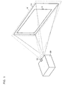
- FIG. 1 is a schematic diagram showing a state during image projection.
- a projector 20 which is one type of an image processing system projects an image onto a screen 10 which is one type of a projection target.
- the projector 20 is not perpendicular to the screen 10.
- a projected image 12 formed by projection light from the projector 20 is larger than the screen 10.
- a wall exists behind the screen 10 and reflects the projection light to allow the projected image 12 to be displayed.
- a sensor 60 which is a part of a sensing means senses a region including the projected image 12.
- the projector 20 calculates the aspect ratio (height/width ratio) of the screen 10 based on sensing information from the sensor 60.
- the projector 20 corrects image distortion based on the calculated aspect ratio and a known aspect ratio of the projected image so that the projected image 12 is displayed within the screen 10 and has an aspect ratio equal to that of the projected image.
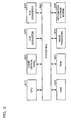
- FIG. 2 is a functional block diagram of the projector 20 according to an example of the present embodiment.
- the projector 20 includes a signal input section 110 to which an image signal is input, a distortion correction section 130 which corrects the input image signal so that image distortion is corrected, a signal output section 160 which outputs the corrected image signal, an image projection section 190 which is one type of an image projection means that projects an image based on the image signal, and a calibration image information generation section 170 which generates calibration image information.
- the projector 20 includes a sensing section 180 which generates sensing information by sensing a region 8 including the projected image 12 through a sensing plane, a projection target region information generation section 140 which is one type of projection target region information generation means that detects the region of the screen 10 in the sensing region of the sensor 60 based on the sensing information, a projection area information generation section 150 which detects the region of the projected image 12 in the sensing region of the sensor 60, and a correction information generation section 120 which generates distortion correction information.
- the sensing section 180 includes the sensor 60.
- the image projection section 190 includes a spatial light modulator 192, a driver section 194 which drives the spatial light modulator 192, a light source 196, and a lens 198.
- the driver section 194 drives the spatial light modulator 192 based on the image signal from the signal output section 160.
- the image projection section 190 projects light from the light source 196 through the spatial light modulator 192 and the lens 198.
- FIG. 3 is a hardware block diagram of the projector 20 according to an example of the present embodiment.
- each section of the projector 20 may be implemented by using an A/D converter 930 or the like as the signal input section 110, an image processing circuit 970, RAM 950, CPU 910, or the like as the distortion correction section 130, a D/A converter 940 or the like as the signal output section 160, the image processing circuit 970, RAM 950, or the like as the correction information generation section 120, projection target region information generation section 140, projection area information generation section 150, and calibration image information generation section 170, a CCD sensor, CMOS sensor, RGB sensor, or the like as the sensing section 180, and a liquid crystal panel 920, ROM 960 which stores a liquid crystal light valve driver which drives the liquid crystal panel 920, or the like as the spatial light modulator 192.
- an A/D converter 930 or the like as the signal input section 110
- an image processing circuit 970, RAM 950, CPU 910, or the like as the distortion correction section 130
- a D/A converter 940 or the like as the signal output section 160
- the function of the projection target region information generation section 140 and the like may be implemented by a computer by reading a program from an information storage medium 900 which stores a program for allowing the computer to operate as the projection target region information generation section 140 and the like.
- the program reading method may be either a contact method or a noncontact method.
- the above-described function may be implemented by downloading a program or the like for implementing each function from a host device or the like through a transmission line instead of reading from the information storage medium 900.
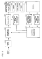
- FIG. 4 is a flowchart showing a flow of image processing according to an example of the present embodiment.
- the calibration image information generation section 170 generates image information for an all-black single-color calibration image (entire image is black), and the signal output section 160 outputs a digital signal of the image information to the image projection section 190.
- the image projection section 190 projects an all-black calibration image onto the screen 10 based on the digital signal (step S1). This allows an all-black calibration image to be displayed on the screen 10.
- the sensing section 180 senses the region including the projected image 12 through the sensing plane to generate first sensing information (step S2).
- the sensing information refers to information which indicates a luminance value or an image signal value which can generate the luminance value, such as an XYZ value, for each pixel of the sensor 60, for example.
- the XYZ value is an international standard defined by International Commission on Illumination (CIE) and is one type of an image signal value for a device independent color.
- FIG. 5 is a schematic diagram showing a sensing region 17 according to an example of the present embodiment.
- the sensing region 17 is a region corresponding to the sensing plane at which the sensor 60 senses an image, and is a region schematically showing the sensing information of the sensor 60 in the shape of a quadrilateral.
- a region of the sensing plane of a CCD sensor or the like applies to the sensing region 17, for example.
- the optical axis of the sensor 60 and the optical axis of the lens 198 face in the same direction, and the projector 20 is not perpendicular to the screen 10. Therefore, when viewed from the sensor 60, the projection area 13 which is the region of the projected image 12 is seen in the shape of a quadrilateral in the same manner as the sensing region 17, and the projection target region 11 which is the region of the screen 10 is distorted, as shown in FIG. 5.
- the projection target region information generation section 140 searches for the luminance value radially outward from the intersecting point P0 of the diagonals of the projection area 13, that is, the center P0 of the projection area 13 (which may not necessarily be the center, but may be near the center).
- the projection target region information generation section 140 detects a line segment P0P1 on which approximately the same luminance value continues from the center P0 as a part of the projection target region 11.
- the projection target region information generation section 140 performs the same processing at a position at an angle of ⁇ to detect a line segment P0P2 as a part of the projection target region 11.
- the distance of the line segment is denoted by L.
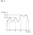
- FIG. 6 is a schematic diagram showing the relationship between the angle ⁇ and the distance L.
- the distance L changes as shown in FIG. 6 as the angle ⁇ ( ⁇ is 0 - 2 ⁇ ) changes, and forms four peaks at angles ⁇ 1, ⁇ 2, ⁇ 3, and ⁇ 4, for example.
- the projection target region information generation section 140 calculates the sensor coordinates of four corners A, B, C, and D of the projection target region 11 from the sensor coordinates of the center P0 of the sensing region 17 (coordinates in the sensing region 17) and the distances L1, L2, L3, and L4 at the angles ⁇ 1, ⁇ 2, ⁇ 3, and ⁇ 4.
- the projection target region information generation section 140 generates projection target region information which shows the sensor coordinates of the four comers (step S3), and sends the projection target region information to the correction information generation section 120.
- the calibration image information generation section 170 generates calibration information for a multi-color calibration image which includes a white image (which may not necessarily be white, but may be a single color such as gray close to white) formed by reducing the original image by an arbitrary factor such as 1/4 at the center and in which the region outside the white image consists of a black image (which may not necessarily be black, but may be a single color such as gray close to black).
- the image projection section 190 projects the multi-color calibration image (step S4).
- the sensing section 180 senses the region 8 including the projected image 12 of the multi-color calibration image projected onto the screen 10 to generate second sensing information (step S5).
- a white region 15 corresponding to the white image is formed inside the projection target region 11 by the second sensing information.
- the projection area information generation section 150 compares the luminance value of each pixel in the white region 15 with the luminance value of each pixel in the projection target region 11 to detect the white region 15 at a constant luminance ratio (step S6).
- the projection area information generation section 150 calculates the sensor coordinates of the projection area 13 by increasing the sensor coordinates of the four corners of the white region 15 by n which is the inverse of the reduction factor.
- the projection area information generation section 150 generates the projection area information which indicates the sensor coordinates of the projection area 13 (step S7), and sends the projection area information to the correction information generation section 120.
- the correction information generation section 120 derives the relative distance between the screen 10 and the sensor 60 on the optical axis of the sensor 60 (step S8).
- the sensor coordinates of the projection target region 11 are denoted by A(Ax, Ay), B(Bx, By), C(Cx, Cy), and D(Dx, Dy)
- the coordinates of the four comers of the screen 10 are denoted by A'(s * Ax, s * Ay, s * Pz), B'(t * Bx, t * By, t * Pz), C'(u * Cx, u * Cy, u * Pz), and D'(v * Dx, v * Dy, v * Pz).
- Pz is the distance on the Z axis from the origin of the sensor coordinate system to the virtual sensing plane as the sensing region 17.
- FIG. 7 is a schematic diagram of the XYZ three-dimensional space according to an example of the present embodiment.
- the relative distances on the optical axis (Z-axis component) from the origin to the four corners A, B, C, and D of the screen 10 can be obtained by assuming that s is 1 (may not necessarily be 1).
- the correction information generation section 120 calculates the aspect ratio of the screen 10 by comparing
- the correction information generation section 120 derives the projection area after correction (step S10).
- FIG. 8 is a schematic diagram of a projection area 19 after correction according to an example of the present embodiment.
- the aspect ratio of the projected image 12 is 4:3 and the aspect ratio of the screen 10 is 4:2, a region which is reduced by 1/6 from the right and left ends of the projection target region 11 in the sensing region 17 is the projection area 19 after correction.
- the aspect ratio of the projected image 12 is generally known such as 4:3 or 16:9.
- the correction information generation section 120 transforms the coordinates of the projection area 19 after correction in the sensing region 17 into the image processing coordinates of the spatial light modulator 192 (step S11).
- the correction information generation section 120 calculates the difference between the image processing coordinates of the spatial light modulator 192 after distortion correction and the image processing coordinates of the spatial light modulator 192 before distortion correction, and generates the difference as image distortion correction information.
- the distortion correction section 130 corrects the image signal based on the image distortion correction information so that image distortion is corrected.
- the external shape of the projection target (screen 10, for example) can be determined based on the difference in the image signal value (luminance value, for example) based on the sensing information.
- the projector 20 can form a single-color region (white or gray close to white, for example) which is reduced in size while maintaining the shape of the original image on the screen 10 by using the multi-color calibration image.
- the projector 20 can determine image distortion by sensing the single-color region formed on the projection target.
- the image processing system or the like can determine the projection position of the image after distortion correction based on the height/width ratio of the projection target determined by sensing and the height/width ratio of the calibration image.
- the image processing system or the like can generate the image distortion correction information which indicates the degree of image adjustment required based on the difference between the projection position of the image after distortion correction and the projection position of the image before distortion correction, whereby distortion of the image can be appropriately corrected.
- the projector 20 can project an image at an original height/width ratio by generating the image distortion correction information so that the image is projected at the original height/width ratio instead of changing the shape of the image corresponding to the shape of the screen 10.
- the projector 20 can automatically correct distortion of the projected image in the vertical direction and the horizontal direction which occurs during use of the projector 20 at an accurate aspect ratio.
- the projector 20 can correct image distortion without being restricted by the vertical and horizontal distortion detection angles of the image by correcting distortion utilizing the frame of the screen 10.
- the projector 20 can display a visually recognizable image on the screen 10, even if the projector 20 is not installed perpendicular to the plane.
- the projector 20 Since the projector 20 is rarely affected by an obstacle on the screen 10 by comparing the luminance value outward from the center when detecting the projection target region 11, the projector 20 can detect the projection target region 11 more accurately.
- the projector 20 uses the two-dimensional coordinates of the sensing region 17 of the sensor 60 and performs the processing on the assumption that the variable s is 1.
- the projector 20 may use the three-dimensional coordinates of the sensor 60 and set the variable s to a value conforming to the actual sensor 60.
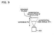
- FIG. 9 is a schematic diagram of the sensing plane of the sensor 60 according to an example of the present embodiment.
- variable Pz is expressed as (W/2)/tan( ⁇ h/2).
- the correction information generation section 120 transforms the three-dimensional coordinates A', B', C', and D' of the screen 10 from the sensor three-dimensional coordinate system (xc, yc, zc) into the projector three-dimensional coordinate system (xp, yp, zp).
- the correction information generation section 120 may transform (xc, yc, zc, 1) into (xp, yp, zp, 1) by using a matrix with four rows and four columns, for example.
- the parameter in the matrix is determined by the positional relationship and the angular relationship between the sensor 60 and the projector 20.
- the correction information generation section 120 calculates the normal vector N(Nx, Ny, Nz) of the screen 10 by using three points among the coordinates a(ax, ay, az) to d(dx, dy, dz) of the four corners of the screen 10 in the projector three-dimensional coordinate system.
- Nx (dy - cy) * (az - dz) - (dz - cz) * (ay - dy)
- Ny (dz - cz) * (ax - dx) - (dx - cx) * (az - dz)
- Zn (dx - cx) * (ay - dy) - (dy - cy) * (ax - dx).
- the correction information generation section 120 searches for the coordinates of the four corners of the projection area after correction from a two-dimensional look-up table by using ⁇ x and ⁇ y.
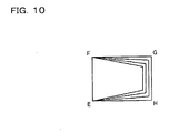
- FIG. 10 is a schematic diagram showing the coordinates of the four corners of the projection area after correction according to an example of the present embodiment.
- FIG. 11 is a two-dimensional look-up table showing the coordinates of the four corners of the projection area after correction according to an example of the present embodiment.
- the values for ⁇ x and ⁇ y are associated with the xy coordinates of the coordinates E, F, G, and H of the four corners of the projection area after correction.
- the correction information generation section 120 generates the image distortion correction information using the xy coordinates of the coordinates E, F, G, and H utilizing the two-dimensional look-up table shown in FIG. 11, and sends the image distortion correction information to the distortion correction section 130.
- This method also enables the projector 20 to correct image distortion based on the coordinates of the four corners of the screen 10.
- the projector 20 for projecting an image at a given aspect ratio is described below.
- the projector 20 can sense the center region of the projected image inside the screen 10 by dividing the projected image 12 equally into nine regions and using the center region as a reference.
- the projector 20 can determine the position of the center region in the sensing region 17 of the sensor 60 by comparing each pixel of an all-black first calibration image with each pixel of a second calibration image in which the center region is white and eight peripheral regions are black.
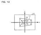
- FIG. 12 is a schematic diagram showing the sensing region 17 in an example of the present embodiment.
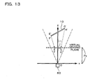
- FIG. 13 is a schematic diagram in the case where the screen 10 according to an example of the present embodiment is perspectively projected with respect to the sensor 60 as the origin.
- the sensor 60 can sense the center region 15 inside the projection target region 11 in the sensing region 17.
- a sensor coordinate system having the center of the sensing region 17 of the sensor 60 as the origin is considered below as an example.
- the horizontal direction of the sensing region 17 is the x-axis
- the vertical direction of the sensing region 17 is the y-axis
- the normal direction of the sensing region 17 is the z-axis.
- the projection target region information generation section 140 generates the projection target region information which indicates the coordinates of the projection target region 11 in the sensor coordinate system.
- the projection area information generation section 150 generates the projection area information which indicates the coordinates of the projection area in the sensor coordinate system.
- the origin O is the center point of the sensing region 17.
- the sensor three-dimensional coordinates of the four vertices of the screen 10 perspectively projected onto the virtual sensing plane are expressed as E(Ex, Ey, Pz), F(Fx, Fy, Pz), G(Gx, Gy, Pz), and H(Hx, Hy, Pz) which have the same z-axis component.
- the four vertices of the actual screen 10 exist ahead of the vertices E, F, G, and H from the origin of the sensor 60, the four vertices of the screen 10 are expressed as s * E(Ex, Ey, Pz), t * F(Fx, Fy, Pz), u * G(Gx, Gy, Pz), and v * H(Hx, Hy, Pz). Note that s, t, u, and v are real numbers.
- the projection target region information generation section 140 can determine the coordinates of the four vertices of the screen 10 in the three-dimensional coordinate system of the sensor 60 by solving s, t, u, and v based on the above condition, and the correction information generation section 120 can determine the aspect ratio of the screen 10 based on the determined coordinates.
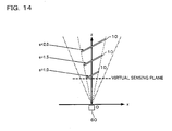
- FIG. 14 is a schematic diagram in the case of changing the variable s in an example of the present embodiment.
- the correction information generation section 120 calculates the aspect ratio by using the three-dimensional coordinates of the four vertices of the screen 10 based on the projection target region information from the projection target region information generation section 140.
- the projected image 12 is corrected so that the aspect ratio of the projected image 12 is 0.75.
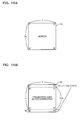
- FIG. 15A shows the screen 10 in which the width is greater than the height.
- FIG. 15B shows the projection area after correction on the screen 10 shown in FIG. 15A.
- FIG. 16A shows the screen 10 in which the width is smaller than the height.
- FIG. 16B shows the projection area after correction on the screen 10 shown in FIG. 16A.
- the correction information generation section 120 In the case where the aspect ratio of the screen 10 is approximately equal to 0.75 (aspect ratio may not necessarily be equal to 0.75 insofar as it is in the allowable range), the correction information generation section 120 generates the correction information so that the shape of the projected image 12 corresponds to the shape of the screen 10. In the present embodiment, the correction information generation section 120 generates the correction information so that the shape of the projected image 12 corresponds to the shape of the screen 10 when the aspect ratio is 0.75 for convenience of description.
- the correction information generation section 120 generates the correction information so that the projection area A'B'C'D' after correction is formed in the region smaller than the screen 10 on the right and left as shown in FIG. 15B.
- the projection area information generation section 150 calculates B', C', and D' in the same manner as A'.
- the correction information generation section 120 generates the correction information so that the projection area A'B'C'D' after correction is formed in the region smaller than the screen 10 at the top and bottom as shown in FIG. 16B.
- the projection area information generation section 150 calculates B', C', and D' in the same manner as A'.
- the projection area information generation section 150 generates the projection area information which indicates the coordinates A', B', C', and D' of the projection area after correction in this manner.
- A', B', C', and D' in the sensor coordinate system determined as described above are perspectively projected onto the screen 10. This transformation processing is performed by setting the depth information z at Pz.
- the correction information generation section 120 calculates B', C', and D' in the same manner as A'.
- FIG. 17 is a schematic diagram showing the projection area 19 after correction in the sensing region 17 in an example of the present embodiment.
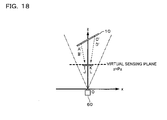
- FIG. 18 is a schematic diagram in the case where the projection area after correction according to an example of the present embodiment is perspectively projected with respect to the sensor 60 as the origin.
- the correction information generation section 120 transforms the coordinates of the projection area after correction on the screen 10 into the coordinates in a liquid crystal panel 920.
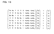
- the correction information generation section 120 generates a coordinate transformation parameter based on the correspondence relationship between the known coordinates A(Ax, Ay), B(Bx, By), C(Cx, Cy), and D(Dx, Dy) of the four vortices of the center region in the sensor coordinate system and the coordinates I(Ix, Iy), J(Jx, Jy), K(Kx, Ky), and L(Lx, Ly) of the four vortices of the center region in the liquid crystal panel 920.
- FIG. 19 shows an arithmetic expression for determining the coordinate transformation parameter according to an example of the present embodiment.
- the correction information generation section 120 transforms the coordinates of the projection area A'B'C'D' after correction into the coordinates in the liquid crystal panel 920 by using coordinate transformation parameters Pa to Ph shown in FIG. 19.
- A'x (Pa * A'x + Pb * A'y + Pc)/(Pg * A'x + Ph * A'y + 1)
- A'y (Pd * A'x + Pe * A'y + Pf)/(Pg * A'x + Ph * A'y + 1). This also applies to the vertices B', C', and D'.
- the correction information generation section 120 generates the correction information based on the difference between the original coordinates in the liquid crystal panel 920 and the coordinates in the liquid crystal panel 920 after correction.
- the distortion correction section 130 corrects the image signal based on the generated correction information.
- the image projection section 190 projects an image based on the corrected image signal.
- the projector 20 can project an image at a desired aspect ratio by effectively utilizing the region of the screen 10. This enables the projector 20 to project an image which is easily seen by an observer without being affected by the shape of the screen 10.
- the projector 20 can appropriately correct an image without being affected by the difference in position between the projector 20 and the sensor 60 by calculating the coordinates using the sensor coordinate system. Therefore, various types of sensing means such as a sensor included in the projector 20, a sensor positioned at a distance from the projector 20, or a digital camera can be employed as the sensor 60.
- the present invention is particularly effective in the case where the projected image 12 includes the screen 10.
- the projector 20 may automatically detect the inclusion relationship between the projected image 12 and the screen 10, and determine the image correction method to be applied corresponding to the detection result.
- the projector 20 may project an image by performing zoom adjustment so that the projected image 12 includes the screen 10, for example.
- the projected image 12 is divided equally into nine regions and the center region is used as the reference.
- the size and position of the center region may be arbitrary insofar as the projector 20 can include the center region of the projected image inside the screen 10.
- the screen 10 is used as the projection target.
- the projection target may be a white board, wall, or the like insofar as the projection target is in the shape of a quadrilateral which allows detection of the four corners.
- the projector 20 is used as the image processing system.
- the present invention is also effective for an image processing system for a display such as a cathode ray tube (CRT), light emitting diode (LED), or electroluminescence (EL) in addition to the projector 20.
- a display such as a cathode ray tube (CRT), light emitting diode (LED), or electroluminescence (EL) in addition to the projector 20.
- CTR cathode ray tube
- LED light emitting diode
- EL electroluminescence
- DMD digital micromirror device
- the function of the projector 20 may be implemented by only a projector, or may be distributed in a plurality of processing devices (distributed processing of projector and PC, for example).
Abstract
Description
- The present invention relates to an image processing system, a projector, an information storage medium, and an image processing method capable of correcting image distortion.
- An image may be distorted due to the relative angle formed by the optical axis of projection light from an image projection device such as a projector and a projection target such as a screen, whereby keystone distortion may occur in the vertical direction or horizontal direction.
- Therefore, the image display device must display an image while climinating distortion of the image.
- A conventional projector with an image distortion correction function corrects image distortion only in the vertical direction using a built-in angle sensor, and cannot correct image distortion in the horizontal direction.
- In the case of correcting image distortion in the horizontal direction, a user points at the four corners of the screen using a mouse or the like, and the projector semi-automatically corrects image distortion based on the point information. However, it is troublesome for the user to point at the four corners of the screen using a mouse or the like.
- In order to solve such a problem, Japanese Patent Application Laid-open No. 2000-241874 has disclosed an automatic screen position adjustment device for a projector which detects the position of the screen in an image sensed by using a monitor camera based on an image signal input from the monitor camera, and adjusts keystone distortion of the projected image based on the detected screen position data.
- In the method disclosed in Japanese Patent Application Laid-open No. 2000-241874, keystone distortion is adjusted by comparing the lengths of opposite sides of the screen in the sensed monitor screen as described in the specification of Japanese Patent Application Laid-open No. 2000-241874.
- However, in the case where the height/width ratio (aspect ratio) of the projection target such as the screen is unknown, the projector cannot appropriately determine image distortion merely by comparing the lengths of opposite sides of the screen.
- Japanese Patent application Laid-open No. 2002-247614 has disclosed a projector which detects the external shape of a screen by using a sensing section, and corrects an image so that the image has an external shape the same as the detected external shape.
- However, if the projector changes the shape of the image into the external shape of the screen as disclosed in Japanese Patent application Laid-open No. 2002-247614, the image after changing has an external shape differing from the external shape of the original image. In this case, since an observer is given an impression differing from the original image, it is not preferable to employ such a processing method.
- Moreover, it is preferable that a projected image be displayed at a desired height/width ratio even if the height/width ratio of the projection target is used as a reference.
- The present invention has been achieved in view of the above-described problems, and may provide an image processing system, a projector, an information storage medium, and an image processing method capable of correcting distortion of a projected image by determining the height/width ratio of the projection target and image distortion.
- To solve the above-described problems, each of an image processing system and projector according to aspects of the present invention includes:
- an image projection means for projecting a single-color calibration image formed of an arbitrary single color onto a projection target, and projecting a multi-color calibration image onto the projection target, the multi-color calibration image including a first region and a second region, the first region being in a first single color and smaller than an entire image region and the second region being a region other than the first region and in a second single color, which is a color other than the first single color;
- a sensing means for sensing the single-color calibration image projected onto the projection target to generate first sensing information, and sensing the multi-color calibration image projected onto the projection target to generate second sensing information;
- a projection target region information generation means for generating projection target region information which indicates coordinates of four corners of the projection target in a sensing region of the sensing means based on a difference in image signal value between each pixel based on the first sensing information;
- a projection area information generation means for detecting the first region in the sensing region as a partial projection area based on a difference between the first sensing information and the second sensing information, and generating projection area information which indicates coordinates of four comers of a projection area in the sensing region based on the partial projection area;
- a correction information generation means for generating image distortion correction information based on the projection target region information and the projection area information; and
- a distortion correction means for correcting an image signal so that image distortion is corrected based on the image distortion correction information, wherein the image projection means projects an image based on the image signal corrected by the distortion correction means.
-
- An information storage medium according to another aspect of the present invention stores a computer-readable program which causes a computer to function as:
- an image projection means for projecting a single-color calibration image formed of an arbitrary single color onto a projection target, and projecting a multi-color calibration image onto the projection target, the multi-color calibration image including a first region and a second region, the first region being in a first single color and smaller than an entire image region and the second region being a region other than the first region and in a second single color, which is a color other than the first single color;
- a sensing means for sensing the single-color calibration image projected onto the projection target to generate first sensing information, and sensing the multi-color calibration image projected onto the projection target to generate second sensing information;
- a projection target region information generation means for generating projection target region information which indicates coordinates of four comers of the projection target in a sensing region of the sensing means based on a difference in image signal value between each pixel based on the first sensing information;
- a projection area information generation means for detecting the first region in the sensing region as a partial projection area based on a difference between the first sensing information and the second sensing information, and generating projection area information which indicates coordinates of four corners of a projection area in the sensing region based on the partial projection area;
- a correction information generation means for generating image distortion correction information based on the projection target region information and the projection area information; and
- a distortion correction means for correcting an image signal so that image distortion is corrected based on the image distortion correction information, wherein the image projection means projects an image based on the image signal corrected by the distortion correction means.
-
- An image processing method according to a further aspect of the present invention includes:
- projecting a single-color calibration image formed of an arbitrary single color onto a projection target by an image projection section;
- sensing the single-color calibration image projected onto the projection target by a sensing section to generate first sensing information;
- projecting a multi-color calibration image onto the projection target, the multi-color calibration image including a first region and a second region, the first region being in a first single color and smaller than an entire image region and the second region being a region other than the first region and in a second single color, which is a color other than the first single color;
- sensing the multi-color calibration image projected onto the projection target to generate second sensing information;
- generating projection target region information which indicates coordinates of four corners of the projection target in a sensing region of the sensing section based on a difference in image signal value between each pixel based on the first sensing information;
- detecting the first region in the sensing region as a partial projection area based on a difference between the first sensing information and the second sensing information, and generating projection area information which indicates coordinates of four corners of a projection area in the sensing region based on the partial projection area;
- generating image distortion correction information based on the projection target region information and the projection area information;
- correcting an image signal so that image distortion is corrected based on the image distortion correction information; and
- projecting an image based on the image signal.
-
- According to the present invention, the image processing system and the like can determine the external shape of the projection target (screen, for example) based on the difference in image signal value (luminance value, for example) based on the sensing information.
- Moreover, according to the present invention, even if the calibration image is projected at a size larger than the projection target, the image processing system and the like can form the region in the first single color (white or gray close to white, for example) which is reduced in size while maintaining the shape of the original image on the projection target by using the multi-color calibration image.
- The image processing system and the like can determine image distortion by sensing the single-color region in the first single color formed on the projection target.
- The image processing system and the like can generate the image distortion correction information which indicates the degree of image adjustment required based on the difference between the projection position of the image after distortion correction and the projection position of the image before distortion correction, whereby image distortion can be appropriately corrected.
- With these image processing system, projector and information storage medium, the first region may be formed by reducing the entire image region by l/n, and the projection area information generation means may detect a region formed by multiplying the partial projection area by n as the projection area.
- With this image processing method, the first region may be formed by reducing the entire image region by l/n, and a region formed by multiplying the partial projection area by n may be detected as the projection area.
- According to this feature, the image processing system and the like can detect the projection area more efficiently.
- With these image processing system, projector and information storage medium, the correction information generation means may:
- calculate a relative distance between an origin in a three-dimensional space in which an optical axis of the sensing means is added to a two-dimensional plane of the sensing region as a third dimension and the four corners of the projection target on the optical axis based on the projection target region information;
- calculate coordinates of the four corners of the projection target in the three-dimensional space based on the projection target region information and the relative distance;
- calculate a first height/width ratio which indicates a height/width ratio of the projection target by calculating lengths of two sides of the projection target which are not opposite each other based on the coordinates;
- calculate coordinates of four corners of an image in the sensing region in a case where the image projection means projects the image onto the projection target in an undistorted state at a second height/width ratio based on the first height/width ratio, the second height/width ratio and the projection target region information, the second height/width ratio indicating a height/width ratio of the single-color calibration image, the multi-color calibration image, or a projection panel of the image projection means; and
- generate the image distortion correction information based on the coordinates of the four corners of the image in the sensing region and the projection area information.
-
- This image processing method may include:
- calculating a relative distance between an origin in a three-dimensional space in which an optical axis of the sensing section is added to a two-dimensional plane of the sensing region as a third dimension and the four corners of the projection target on the optical axis based on the projection target region information;
- calculating coordinates of the four corners of the projection target in the three-dimensional space based on the projection target region information and the relative distance;
- calculating a first height/width ratio which indicates a height/width ratio of the projection target by calculating lengths of two sides of the projection target which are not opposite each other based on the coordinates;
- calculating coordinates of four comers of an image in the sensing region in a case of projecting the image onto the projection target in an undistorted state at a second height/width ratio based on the first height/width ratio, the second height/width ratio and the projection target region information, the second height/width ratio indicating a height/width ratio of the single-color calibration image, the multi-color calibration image, or a projection panel of the image projection section; and
- generating the image distortion correction information based on the coordinates of the four corners of the image in the sensing region and the projection area information.
-
- An image processing system and a projector according to still further aspects of the present invention includes:
- an image projection means for projecting a calibration image onto a projection target;
- a sensing means for sensing the calibration image to generate sensing information;
- a projection target region information generation means for generating projection target region information which indicates coordinates of four corners of the projection target in a sensing region of the sensing means based on the sensing information;
- a projection area information generation means for generating projection area information which indicates coordinates of four comers of a projection area in the sensing region based on the sensing information;
- a correction information generation means for generating image distortion correction information based on the projection target region information and the projection area information; and
- a distortion correction means for correcting an image signal based on the image distortion correction information so that image distortion is corrected, wherein the image projection means projects an image based on the image signal that has been corrected by the distortion correction means, and
-
- An information storage medium according to an even further aspect of the present invention stores a computer-readable program which causes a computer to function as:
- an image projection means for projecting a calibration image onto a projection target;
- a sensing means for scnsing the calibration image to generate sensing information;
- a projection target region information generation means for generating projection target region information which indicates coordinates of four corners of the projection target in a sensing region of the sensing means based on the sensing information;
- a projection area information generation means for generating projection area information which indicates coordinates of four corners of a projection area in the sensing region based on the sensing information;
- a correction information generation means for generating image distortion correction information so that an image is projected onto the projection target region at a desired height/width ratio, based on the projection target region information and the projection area information; and
- a distortion correction means for correcting an image signal based on the image distortion correction information so that image distortion is corrected, wherein the image projection means projects an image based on the image signal that has been corrected by the distortion correction means, and
-
- A yet further aspect of the present invention relates to an information storage medium storing a computer-readable program which stores the above program.
- An image processing method according to an even more aspect of the present invention includes:
- projecting a calibration image onto a projection target by an image projection section;
- sensing the calibration image by a sensing section to generate sensing information;
- generating projection target region information which indicates coordinates of four corners of the projection target in a sensing region of the sensing section based on the sensing information;
- generating projection area information which indicates coordinates of four comers of a projection area in the sensing region based on the sensing information;
- generating projection coordinate system projection area information which indicates coordinates of four corners of the projection area in a projection panel of the image projection section based on the projection area information;
- determining a first height/width ratio which indicates a height/width ratio of the projection target based on the projection coordinate system projection area information;
- generating image distortion correction information so that an image is projected at a second height/width ratio which indicates a desired height/width ratio corresponding to the first height/width ratio;
- correcting an image signal based on the image distortion correction information so that image distortion is corrected; and
- projecting an image based on the corrected image signal.
-
- According to the present invention, the image processing system and the like can display an image at an original height/width ratio by generating the image distortion correction information so that the image is projected at the original height/width ratio instead of changing the shape of the image corresponding to the shape of the projection target.
- With any of these image processing systems, projectors and information storage mediums, the correction information generation means may determine a first height/width ratio which indicates a height/width ratio of the projection target based on the projection target region information, and may generate projection coordinate system projection area information which indicates coordinates of four corners of the projection area in a projection panel of the image projection means based on the projection area information and may generate the image distortion correction information based on the projection coordinate system projection area information so that an image is displayed at a second height/width ratio which indicates a desired height/width ratio corresponding to the first height/width ratio.
- Any of these image processing methods may include:
- determining a first height/width ratio which indicates a height/width ratio of the projection target based on the projection target region information;
- generating projection coordinate system projection area information which indicates coordinates of four corners of the projection area in a projection panel based on the projection area information so that an image is displayed at a second height/width ratio which indicates a desired height/width ratio corresponding to the first height/width ratio; and
- generating the image distortion correction information based on the projection coordinate system projection area information.
-
- According to this feature, the image processing system and the like can display an image at a desired height/width ratio irrespective of the shape of the projection target by generating the image distortion correction information so that the image is displayed at a desired height/width ratio instead of changing the shape of the image corresponding to the shape of the projection target.
- With any of these image processing systems, projectors and information storage mcdiums, the correction information generation means may:
- calculate a relative distance between an origin in a three-dimensional space in which an optical axis of the sensing means is added to a two-dimensional plane of the sensing region as a third dimension and the four corners of the projection target on the optical axis based on the projection target region information;
- calculate coordinates of the four corners of the projection target in the three-dimensional space based on the projection target region information and the relative distance; and
- calculate a first height/width ratio by calculating lengths of two sides of the projection target which are not opposite each other based on the coordinates.
-
- Any of these image processing methods may include:
- calculating a relative distance between an origin in a three-dimensional space in which an optical axis of the sensing section is added to a two-dimensional plane of the sensing region as a third dimension and the four corners of the projection target on the optical axis based on the projection target region information;
- calculating coordinates of the four corners of the projection target in the three-dimensional space based on the projection target region information and the relative distance; and
- calculating a first height/width ratio by calculating lengths of two sides of the projection target which are not opposite each other based on the coordinates.
-
- According to this feature, the image processing system and the like can increase the degrees of freedom on installation of the sensing means by executing image processing in the three-dimensional space based on the sensing means.
- With any of these image processing systems, projectors and information storage mediums, the projection target region information generation means may search for an image signal value of the sensing information so that each pixel is radially searched for from a region near a center of the sensing region, and may generate the projection target region information by determining the projection target region based on a difference in the image signal value during searching.
- Any of these image processing methods may include searching for an image signal value of the sensing information so that each pixel is radially searched for from a region near a center of the sensing region, and generating the projection target region information by determining the projection target region based on a difference in the image signal value during searching when generating the projection target region information.
- According to this feature, the image processing system and the like are rarely affected by noise by searching for the image signal value of the sensing information so that each pixel is radially searched for from a region near the center of the sensing information, whereby the projection target region can be detected more accurately.
-
- FIG. 1 is a schematic diagram showing a state during image projection.
- FIG. 2 is a functional block diagram of a projector according to an example of an embodiment of the present invention.
- FIG. 3 is a hardware block diagram of a projector according to an example of an embodiment of the present invention.
- FIG. 4 is a flowchart showing a flow of image processing according to an example of an embodiment of the present invention.
- FIG. 5 is a schematic diagram showing a sensing region according to an example of an embodiment of the present invention.
- FIG. 6 is a schematic diagram showing the relationship between an angle and a distance L.
- FIG. 7 is a schematic diagram of an XYZ three-dimensional space according to an example of an embodiment of the present invention.
- FIG. 8 is a schematic diagram of a projection area after correction according to an example of an embodiment of the present invention.
- FIG. 9 is a schematic diagram of a sensing plane of a sensor according to an example of an embodiment of the present invention.
- FIG. 10 is a schematic diagram showing coordinates of four corners of a projection area after correction according to an example of an embodiment of the present invention.
- FIG. 11 is a two-dimensional look-up table showing coordinates of four corners of a projection area after correction according to an example of an embodiment of the present invention.
- FIG. 12 is a schematic diagram showing a sensing region in an example of an embodiment of the present invention.
- FIG. 13 is a schematic diagram in the case where a screen according to an example of an embodiment of the present invention is perspectively projected by using a sensor as the origin.
- FIG. 14 is a schematic diagram in the case of changing a variable s in an example of an embodiment of the present invention.
- FIG. 15A shows a screen in which the width is greater than the height, and FIG. 15B is view showing a projection area after correction on the screen shown in FIG. 15A.
- FIG. 16A shows a screen in which the height is greater than the width, and FIG. 16B is view showing a projection area after correction on the screen shown in FIG. 16A.
- FIG. 17 is a schematic diagram showing a projection area after correction in a sensing region in an example of an embodiment of the present invention.
- FIG. 18 is a schematic diagram in the case where a projection area after correction according to an example of an embodiment of the present invention is perspectively projected with respect to a sensor as the origin.
- FIG. 19 shows an arithmetic expression for determining coordinate transformation parameters according to an example of an embodiment of the present invention.
-
- The present invention is described below with reference to the drawings taking the case of applying the present invention to a projector which corrects image distortion as an example. Note that the embodiments described below do not in any way limit the scope of the invention defined by the claims laid out herein. Note also that all the elements of the embodiments described below should not be taken as essential requirements for the invention defined by the claims laid out herein.
- FIG. 1 is a schematic diagram showing a state during image projection.
- A
projector 20 which is one type of an image processing system projects an image onto ascreen 10 which is one type of a projection target. In the present embodiment, theprojector 20 is not perpendicular to thescreen 10. A projectedimage 12 formed by projection light from theprojector 20 is larger than thescreen 10. In the present embodiment, a wall exists behind thescreen 10 and reflects the projection light to allow the projectedimage 12 to be displayed. - In the present embodiment, a
sensor 60 which is a part of a sensing means senses a region including the projectedimage 12. - In the present embodiment, the
projector 20 calculates the aspect ratio (height/width ratio) of thescreen 10 based on sensing information from thesensor 60. Theprojector 20 corrects image distortion based on the calculated aspect ratio and a known aspect ratio of the projected image so that the projectedimage 12 is displayed within thescreen 10 and has an aspect ratio equal to that of the projected image. - Functional blocks of the
projector 20 for implementing the above-described function is described below. - FIG. 2 is a functional block diagram of the
projector 20 according to an example of the present embodiment. - The
projector 20 includes asignal input section 110 to which an image signal is input, adistortion correction section 130 which corrects the input image signal so that image distortion is corrected, asignal output section 160 which outputs the corrected image signal, animage projection section 190 which is one type of an image projection means that projects an image based on the image signal, and a calibration imageinformation generation section 170 which generates calibration image information. - The
projector 20 includes asensing section 180 which generates sensing information by sensing aregion 8 including the projectedimage 12 through a sensing plane, a projection target regioninformation generation section 140 which is one type of projection target region information generation means that detects the region of thescreen 10 in the sensing region of thesensor 60 based on the sensing information, a projection areainformation generation section 150 which detects the region of the projectedimage 12 in the sensing region of thesensor 60, and a correctioninformation generation section 120 which generates distortion correction information. Thesensing section 180 includes thesensor 60. - The
image projection section 190 includes a spatiallight modulator 192, adriver section 194 which drives the spatiallight modulator 192, alight source 196, and alens 198. - The
driver section 194 drives the spatiallight modulator 192 based on the image signal from thesignal output section 160. Theimage projection section 190 projects light from thelight source 196 through the spatiallight modulator 192 and thelens 198. - As hardware for implementing each section of the
projector 20, the following hardware may be applied, for example. - FIG. 3 is a hardware block diagram of the
projector 20 according to an example of the present embodiment. - For example, each section of the
projector 20 may be implemented by using an A/D converter 930 or the like as thesignal input section 110, animage processing circuit 970,RAM 950,CPU 910, or the like as thedistortion correction section 130, a D/A converter 940 or the like as thesignal output section 160, theimage processing circuit 970,RAM 950, or the like as the correctioninformation generation section 120, projection target regioninformation generation section 140, projection areainformation generation section 150, and calibration imageinformation generation section 170, a CCD sensor, CMOS sensor, RGB sensor, or the like as thesensing section 180, and aliquid crystal panel 920,ROM 960 which stores a liquid crystal light valve driver which drives theliquid crystal panel 920, or the like as the spatiallight modulator 192. - These sections can exchange information through a
system bus 980. - Some or the entirety of these sections may be implemented by hardware such as a circuit or may be implemented by software such as a driver.
- The function of the projection target region
information generation section 140 and the like may be implemented by a computer by reading a program from aninformation storage medium 900 which stores a program for allowing the computer to operate as the projection target regioninformation generation section 140 and the like. - As the
information storage medium 900, a CD-ROM, DVD-ROM, ROM, RAM, HDD, or the like may be applied. The program reading method may be either a contact method or a noncontact method. - The above-described function may be implemented by downloading a program or the like for implementing each function from a host device or the like through a transmission line instead of reading from the
information storage medium 900. - An image processing flow using these sections is described below.
- FIG. 4 is a flowchart showing a flow of image processing according to an example of the present embodiment.
- The calibration image
information generation section 170 generates image information for an all-black single-color calibration image (entire image is black), and thesignal output section 160 outputs a digital signal of the image information to theimage projection section 190. - The
image projection section 190 projects an all-black calibration image onto thescreen 10 based on the digital signal (step S1). This allows an all-black calibration image to be displayed on thescreen 10. - The
sensing section 180 senses the region including the projectedimage 12 through the sensing plane to generate first sensing information (step S2). The sensing information refers to information which indicates a luminance value or an image signal value which can generate the luminance value, such as an XYZ value, for each pixel of thesensor 60, for example. The XYZ value is an international standard defined by International Commission on Illumination (CIE) and is one type of an image signal value for a device independent color. - FIG. 5 is a schematic diagram showing a
sensing region 17 according to an example of the present embodiment. - The
sensing region 17 is a region corresponding to the sensing plane at which thesensor 60 senses an image, and is a region schematically showing the sensing information of thesensor 60 in the shape of a quadrilateral. In more detail, a region of the sensing plane of a CCD sensor or the like applies to thesensing region 17, for example. - In the present embodiment, the optical axis of the
sensor 60 and the optical axis of thelens 198 face in the same direction, and theprojector 20 is not perpendicular to thescreen 10. Therefore, when viewed from thesensor 60, theprojection area 13 which is the region of the projectedimage 12 is seen in the shape of a quadrilateral in the same manner as thesensing region 17, and theprojection target region 11 which is the region of thescreen 10 is distorted, as shown in FIG. 5. - In the present embodiment, the projection target region
information generation section 140 searches for the luminance value radially outward from the intersecting point P0 of the diagonals of theprojection area 13, that is, the center P0 of the projection area 13 (which may not necessarily be the center, but may be near the center). The projection target regioninformation generation section 140 detects a line segment P0P1 on which approximately the same luminance value continues from the center P0 as a part of theprojection target region 11. The projection target regioninformation generation section 140 performs the same processing at a position at an angle of to detect a line segment P0P2 as a part of theprojection target region 11. The distance of the line segment is denoted by L. - FIG. 6 is a schematic diagram showing the relationship between the angle and the distance L.
- The distance L changes as shown in FIG. 6 as the angle ( is 0 - 2π) changes, and forms four peaks at angles 1, 2, 3, and 4, for example.
- The projection target region
information generation section 140 calculates the sensor coordinates of four corners A, B, C, and D of theprojection target region 11 from the sensor coordinates of the center P0 of the sensing region 17 (coordinates in the sensing region 17) and the distances L1, L2, L3, and L4 at the angles 1, 2, 3, and 4. - The projection target region
information generation section 140 generates projection target region information which shows the sensor coordinates of the four comers (step S3), and sends the projection target region information to the correctioninformation generation section 120. - The calibration image
information generation section 170 generates calibration information for a multi-color calibration image which includes a white image (which may not necessarily be white, but may be a single color such as gray close to white) formed by reducing the original image by an arbitrary factor such as 1/4 at the center and in which the region outside the white image consists of a black image (which may not necessarily be black, but may be a single color such as gray close to black). Theimage projection section 190 projects the multi-color calibration image (step S4). - The
sensing section 180 senses theregion 8 including the projectedimage 12 of the multi-color calibration image projected onto thescreen 10 to generate second sensing information (step S5). - As shown in FIG. 5, a
white region 15 corresponding to the white image is formed inside theprojection target region 11 by the second sensing information. - The projection area
information generation section 150 compares the luminance value of each pixel in thewhite region 15 with the luminance value of each pixel in theprojection target region 11 to detect thewhite region 15 at a constant luminance ratio (step S6). - The projection area
information generation section 150 calculates the sensor coordinates of theprojection area 13 by increasing the sensor coordinates of the four corners of thewhite region 15 by n which is the inverse of the reduction factor. - The projection area
information generation section 150 generates the projection area information which indicates the sensor coordinates of the projection area 13 (step S7), and sends the projection area information to the correctioninformation generation section 120. - The correction
information generation section 120 derives the relative distance between thescreen 10 and thesensor 60 on the optical axis of the sensor 60 (step S8). - In more detail, in the case where the sensor coordinates of the
projection target region 11 are denoted by A(Ax, Ay), B(Bx, By), C(Cx, Cy), and D(Dx, Dy), in the XYZ three-dimensional space in which the optical axis of thesensor 60 is added to the two-dimensional plane XY of thesensing region 17 of thesensor 60 as a third dimension Z, the coordinates of the four comers of thescreen 10 are denoted by A'(s * Ax, s * Ay, s * Pz), B'(t * Bx, t * By, t * Pz), C'(u * Cx, u * Cy, u * Pz), and D'(v * Dx, v * Dy, v * Pz). Pz is the distance on the Z axis from the origin of the sensor coordinate system to the virtual sensing plane as thesensing region 17. The projection target regioninformation generation section 140 determines Pz by calculating Pz = (VR/2)/tan(c/2) based on the relationship between the horizontal view angle 0c and the horizontal resolution VR of thesensor 60. - FIG. 7 is a schematic diagram of the XYZ three-dimensional space according to an example of the present embodiment.
- Since the
screen 10 is known to be rectangular (may be square), the line segment A'B' equals the line segment D'C'. t, u, and v are expressed as follows on the assumption that this condition is satisfied. - The relative distances on the optical axis (Z-axis component) from the origin to the four corners A, B, C, and D of the
screen 10 can be obtained by assuming that s is 1 (may not necessarily be 1). - The correction
information generation section 120 calculates the aspect ratio of thescreen 10 by comparing |A'B'| and |B'C'| which show the lengths of two sides of thescreen 10 which are not opposite each other. - The correction
information generation section 120 derives the projection area after correction (step S10). - FIG. 8 is a schematic diagram of a
projection area 19 after correction according to an example of the present embodiment. - In the case where the aspect ratio of the projected
image 12 is 4:3 and the aspect ratio of thescreen 10 is 4:2, a region which is reduced by 1/6 from the right and left ends of theprojection target region 11 in thesensing region 17 is theprojection area 19 after correction. The aspect ratio of the projectedimage 12 is generally known such as 4:3 or 16:9. - The correction
information generation section 120 transforms the coordinates of theprojection area 19 after correction in thesensing region 17 into the image processing coordinates of the spatial light modulator 192 (step S11). - The correction
information generation section 120 calculates the difference between the image processing coordinates of the spatiallight modulator 192 after distortion correction and the image processing coordinates of the spatiallight modulator 192 before distortion correction, and generates the difference as image distortion correction information. - The
distortion correction section 130 corrects the image signal based on the image distortion correction information so that image distortion is corrected. - This enables the
image projection section 190 to project an image after distortion correction. - As described above, according to the present embodiment, the external shape of the projection target (
screen 10, for example) can be determined based on the difference in the image signal value (luminance value, for example) based on the sensing information. - According to the present embodiment, even if the
calibration image 12 is projected at a size larger than thescreen 10, theprojector 20 can form a single-color region (white or gray close to white, for example) which is reduced in size while maintaining the shape of the original image on thescreen 10 by using the multi-color calibration image. - The
projector 20 can determine image distortion by sensing the single-color region formed on the projection target. - The image processing system or the like can determine the projection position of the image after distortion correction based on the height/width ratio of the projection target determined by sensing and the height/width ratio of the calibration image. The image processing system or the like can generate the image distortion correction information which indicates the degree of image adjustment required based on the difference between the projection position of the image after distortion correction and the projection position of the image before distortion correction, whereby distortion of the image can be appropriately corrected.
- According to the present embodiment, the
projector 20 can project an image at an original height/width ratio by generating the image distortion correction information so that the image is projected at the original height/width ratio instead of changing the shape of the image corresponding to the shape of thescreen 10. - Therefore, according to the present embodiment, the
projector 20 can automatically correct distortion of the projected image in the vertical direction and the horizontal direction which occurs during use of theprojector 20 at an accurate aspect ratio. In particular, theprojector 20 can correct image distortion without being restricted by the vertical and horizontal distortion detection angles of the image by correcting distortion utilizing the frame of thescreen 10. - Since the linear component of the projection area after correction is in parallel to the frame of the
screen 10, theprojector 20 can display a visually recognizable image on thescreen 10, even if theprojector 20 is not installed perpendicular to the plane. - Since the
projector 20 is rarely affected by an obstacle on thescreen 10 by comparing the luminance value outward from the center when detecting theprojection target region 11, theprojector 20 can detect theprojection target region 11 more accurately. - The application of the present invention is not limited to the above-described embodiment.
- In the above-described embodiment, the
projector 20 uses the two-dimensional coordinates of thesensing region 17 of thesensor 60 and performs the processing on the assumption that the variable s is 1. However, theprojector 20 may use the three-dimensional coordinates of thesensor 60 and set the variable s to a value conforming to theactual sensor 60. - FIG. 9 is a schematic diagram of the sensing plane of the
sensor 60 according to an example of the present embodiment. - In the case where the horizontal resolution of the
sensor 60 is denoted by W and the horizontal view angle of thesensor 60 is denoted by h, the variable Pz is expressed as (W/2)/tan(h/2). - The correction
information generation section 120 transforms the three-dimensional coordinates A', B', C', and D' of thescreen 10 from the sensor three-dimensional coordinate system (xc, yc, zc) into the projector three-dimensional coordinate system (xp, yp, zp). In more detail, the correctioninformation generation section 120 may transform (xc, yc, zc, 1) into (xp, yp, zp, 1) by using a matrix with four rows and four columns, for example. The parameter in the matrix is determined by the positional relationship and the angular relationship between thesensor 60 and theprojector 20. - The correction
information generation section 120 calculates the normal vector N(Nx, Ny, Nz) of thescreen 10 by using three points among the coordinates a(ax, ay, az) to d(dx, dy, dz) of the four corners of thescreen 10 in the projector three-dimensional coordinate system. - In the case of calculating the normal vector by using a, c, and d, Nx = (dy - cy) * (az - dz) - (dz - cz) * (ay - dy), Ny = (dz - cz) * (ax - dx) - (dx - cx) * (az - dz), and Zn = (dx - cx) * (ay - dy) - (dy - cy) * (ax - dx).
- Since the angle formed by the normal vector N and the vector (0, 0, 1) (horizontal x, vertical y) corresponds to the angle formed by the
screen 10 and the optical axis of the projection light of theprojector 20, the correctioninformation generation section 120 searches for the coordinates of the four corners of the projection area after correction from a two-dimensional look-up table by using x and y. - FIG. 10 is a schematic diagram showing the coordinates of the four corners of the projection area after correction according to an example of the present embodiment. FIG. 11 is a two-dimensional look-up table showing the coordinates of the four corners of the projection area after correction according to an example of the present embodiment.
- As shown in FIG. 11, in the two-dimensional look-up table, the values for x and y are associated with the xy coordinates of the coordinates E, F, G, and H of the four corners of the projection area after correction.
- The correction
information generation section 120 generates the image distortion correction information using the xy coordinates of the coordinates E, F, G, and H utilizing the two-dimensional look-up table shown in FIG. 11, and sends the image distortion correction information to thedistortion correction section 130. - This method also enables the
projector 20 to correct image distortion based on the coordinates of the four corners of thescreen 10. - The
projector 20 for projecting an image at a given aspect ratio is described below. - For example, even if a part of the projected
image 12 is projected outside thescreen 10 as shown in FIG. 1, theprojector 20 can sense the center region of the projected image inside thescreen 10 by dividing the projectedimage 12 equally into nine regions and using the center region as a reference. - For example, the
projector 20 can determine the position of the center region in thesensing region 17 of thesensor 60 by comparing each pixel of an all-black first calibration image with each pixel of a second calibration image in which the center region is white and eight peripheral regions are black. - FIG. 12 is a schematic diagram showing the
sensing region 17 in an example of the present embodiment. FIG. 13 is a schematic diagram in the case where thescreen 10 according to an example of the present embodiment is perspectively projected with respect to thesensor 60 as the origin. - In this case, the
sensor 60 can sense thecenter region 15 inside theprojection target region 11 in thesensing region 17. - A sensor coordinate system having the center of the
sensing region 17 of thesensor 60 as the origin is considered below as an example. In the sensor coordinate system, the horizontal direction of thesensing region 17 is the x-axis, the vertical direction of thesensing region 17 is the y-axis, and the normal direction of thesensing region 17 is the z-axis. - The projection target region
information generation section 140 generates the projection target region information which indicates the coordinates of theprojection target region 11 in the sensor coordinate system. The projection areainformation generation section 150 generates the projection area information which indicates the coordinates of the projection area in the sensor coordinate system. - The coordinates of the four comers of the
projection target region 11 in thesensing region 17 are denoted by E (Ex, Ey), F (Fx, Fy), G (Gx, Gy), and H (Hx, Hy). These two-dimensional coordinates correspond to the coordinates obtained by perspectively projecting four vertices E', F', G', and H' of thescreen 10 which exists in the three-dimensional space onto a virtual sensing plane z = Pz which exists in the normal direction of the origin O of thesensor 60. The origin O is the center point of thesensing region 17. - Therefore, the sensor three-dimensional coordinates of the four vertices of the
screen 10 perspectively projected onto the virtual sensing plane are expressed as E(Ex, Ey, Pz), F(Fx, Fy, Pz), G(Gx, Gy, Pz), and H(Hx, Hy, Pz) which have the same z-axis component. The projection target regioninformation generation section 140 can determine Pz by calculating Pz = (VR/2)/tan(c/2) based on the relationship between the horizontal view angle c and the horizontal resolution VR of thesensor 60. - Since the four vertices of the
actual screen 10 exist ahead of the vertices E, F, G, and H from the origin of thesensor 60, the four vertices of thescreen 10 are expressed as s * E(Ex, Ey, Pz), t * F(Fx, Fy, Pz), u * G(Gx, Gy, Pz), and v * H(Hx, Hy, Pz). Note that s, t, u, and v are real numbers. - Since the
screen 10 is rectangular, the side E'F' and the side G'H' are in parallel and equal in length and the side E'H' and the side F'G' are in parallel and equal in length. The projection target regioninformation generation section 140 can determine the coordinates of the four vertices of thescreen 10 in the three-dimensional coordinate system of thesensor 60 by solving s, t, u, and v based on the above condition, and the correctioninformation generation section 120 can determine the aspect ratio of thescreen 10 based on the determined coordinates. - From the above presupposition, E'F' = (t * Fx - s * Ex, t * Fy - s * Ey, t * Pz - s * Pz) and H'G' = (u * Gx - v * Hx, u * Gy - v * Hy, u * Pz - v * Pz).
- And t * Fx - s * Ex equals u * Gx - v * Hx, t * Fy - s * Ey equals u * Gy - v * Hy, and t * Pz - s * Pz equals u * Pz - v * Pz. Therefore, t * Fx - u * Gx + v * Hx = s * Ex ...(1), t * Fy - u * Gy + v * Hy = s * Ey ...(2), and t * Pz - u * Pz + v * Pz = s * Pz ...(3) are obtained.
- Substituting the value obtained by multiplying the equation (4) by Hx into the equation (1) yields (Fx - Hx) * t + (Hx - Gx) * u = (Ex - Hx) * s ...(5).
- Substituting the value obtained by multiplying the equation (4) by Hx into the equation (2) yields (Fy - Hy) * t + (Hy - Gy) * u = (Ey - Hy) * s ...(6).
- In the equations (5) and (6), suppose that a = (Fx - Hx), b = (Hx - Gx), c = (Ex - Hx), d = (Fy - Hy), e = (Hy - Gy), and f = (Ey - Hy). In this case, the equation (5) is expressed as a * t + b * u = c * s, and the equation (6) is expressed as d * t + e * u = f * s.
- Solving these equations yields t = s * (c * c - b * f)/(e * a - b * d) and u = s * (d * c - a * f)/(d * b - a * e). Specifically, t and u can be expressed by using s. The position of the
screen 10 in the case of changing the variable s which shows the depth information is described below. - FIG. 14 is a schematic diagram in the case of changing the variable s in an example of the present embodiment.
- As shown in FIG. 14, since the shape of the
screen 10 is similar even if the variable s is changed, the aspect ratio is invariable. Therefore, the aspect ratio can be calculated by assuming that s = 1. If s = 1, t = (e * c - b * f)/(e * a - b * d), u = (d * c - a * f)/(d * b - a * e), and v = l - t * u. - The correction
information generation section 120 calculates the aspect ratio by using the three-dimensional coordinates of the four vertices of thescreen 10 based on the projection target region information from the projection target regioninformation generation section 140. The aspect ratio used herein refers to the ratio of the length of the horizontal side of the target region to the length of the vertical side of the target region. In the case where horizontal length:vertical length = 4:3, the aspect ratio is 3/4 = 0.75. In the present embodiment, the projectedimage 12 is corrected so that the aspect ratio of the projectedimage 12 is 0.75. - FIG. 15A shows the
screen 10 in which the width is greater than the height. FIG. 15B shows the projection area after correction on thescreen 10 shown in FIG. 15A. FIG. 16A shows thescreen 10 in which the width is smaller than the height. FIG. 16B shows the projection area after correction on thescreen 10 shown in FIG. 16A. - In the case where the aspect ratio of the
screen 10 is approximately equal to 0.75 (aspect ratio may not necessarily be equal to 0.75 insofar as it is in the allowable range), the correctioninformation generation section 120 generates the correction information so that the shape of the projectedimage 12 corresponds to the shape of thescreen 10. In the present embodiment, the correctioninformation generation section 120 generates the correction information so that the shape of the projectedimage 12 corresponds to the shape of thescreen 10 when the aspect ratio is 0.75 for convenience of description. - As shown in FIG. 15A, in the case where the aspect ratio is smaller than 0.75, specifically, the width of the
screen 10 is greater than its height, the correctioninformation generation section 120 generates the correction information so that the projection area A'B'C'D' after correction is formed in the region smaller than thescreen 10 on the right and left as shown in FIG. 15B. - In the case where the aspect ratio Sa is smaller than 0.75, since A' is the point which divides E'H' at a ratio of m:n, A' = (n * E' + m * H')/(m + n). Note that m + n = 1.
- Since height:width of the
screen 10 = sa:1, it is necessary that m = (1 - 4 * Sa/3)/2 and n = 1 - (1 - 4 * Sa/3)/2 in order to maintain the aspect ratio of the projection area after correction at 0.75. The projection areainformation generation section 150 calculates B', C', and D' in the same manner as A'. - As shown in FIG. 16A, in the case where the aspect ratio is greater than 0.75, specifically, the height of the
screen 10 is greater than the width, the correctioninformation generation section 120 generates the correction information so that the projection area A'B'C'D' after correction is formed in the region smaller than thescreen 10 at the top and bottom as shown in FIG. 16B. - In the case where the aspect ratio Sa is greater than 0.75, since A' is the point which divides E'F' at a ratio of m:n, A' = (n * E' + m * F')/(m + n). Note that m + n = 1.
- Since height:width of the
screen 10 = sa:1, it is necessary that m = (Sa - 3/4)/2 and n = Sa - (Sa - 3/4)/2 in order to maintain the aspect ratio of the projection area after correction at 0.75. The projection areainformation generation section 150 calculates B', C', and D' in the same manner as A'. - The projection area
information generation section 150 generates the projection area information which indicates the coordinates A', B', C', and D' of the projection area after correction in this manner. - The correction
information generation section 120 may generate the correction information so that the projection area after correction is increased to some extent based on the projection area information from the projection areainformation generation section 150. This enables image appearance to be improved as a frameless image. If the magnification factor is denoted by Ps and the intersecting point of the diagonal lines of the projection area after correction is denoted by P, the correctioninformation generation section 120 calculates the vertex A' of the projection area after magnification as shown by A' = Ps * PA' + OP. The correctioninformation generation section 120 calculates B', C', and D' in the same manner as A'. - A', B', C', and D' in the sensor coordinate system determined as described above are perspectively projected onto the
screen 10. This transformation processing is performed by setting the depth information z at Pz. - For example, the correction
information generation section 120 calculates the coordinates of the vertex A' as A'x = A'x/A'z * Pz, A'y = A'y/A'z * Pz, and A'z = A'z/A'z * Pz. The correctioninformation generation section 120 calculates B', C', and D' in the same manner as A'. - FIG. 17 is a schematic diagram showing the
projection area 19 after correction in thesensing region 17 in an example of the present embodiment. FIG. 18 is a schematic diagram in the case where the projection area after correction according to an example of the present embodiment is perspectively projected with respect to thesensor 60 as the origin. - The correction
information generation section 120 transforms the coordinates of the projection area after correction on thescreen 10 into the coordinates in aliquid crystal panel 920. - The correction
information generation section 120 generates a coordinate transformation parameter based on the correspondence relationship between the known coordinates A(Ax, Ay), B(Bx, By), C(Cx, Cy), and D(Dx, Dy) of the four vortices of the center region in the sensor coordinate system and the coordinates I(Ix, Iy), J(Jx, Jy), K(Kx, Ky), and L(Lx, Ly) of the four vortices of the center region in theliquid crystal panel 920. - FIG. 19 shows an arithmetic expression for determining the coordinate transformation parameter according to an example of the present embodiment.
- The correction
information generation section 120 transforms the coordinates of the projection area A'B'C'D' after correction into the coordinates in theliquid crystal panel 920 by using coordinate transformation parameters Pa to Ph shown in FIG. 19. - In the case of the vertex A', A'x = (Pa * A'x + Pb * A'y + Pc)/(Pg * A'x + Ph * A'y + 1) and A'y = (Pd * A'x + Pe * A'y + Pf)/(Pg * A'x + Ph * A'y + 1). This also applies to the vertices B', C', and D'.
- The correction
information generation section 120 generates the correction information based on the difference between the original coordinates in theliquid crystal panel 920 and the coordinates in theliquid crystal panel 920 after correction. Thedistortion correction section 130 corrects the image signal based on the generated correction information. Theimage projection section 190 projects an image based on the corrected image signal. - This enables the
projector 20 to project an image without distortion at the center of thescreen 10 by effectively utilizing thescreen 10 as much as possible. - As described above, according to the present embodiment, the
projector 20 can project an image at a desired aspect ratio by effectively utilizing the region of thescreen 10. This enables theprojector 20 to project an image which is easily seen by an observer without being affected by the shape of thescreen 10. - Moreover, the
projector 20 can appropriately correct an image without being affected by the difference in position between theprojector 20 and thesensor 60 by calculating the coordinates using the sensor coordinate system. Therefore, various types of sensing means such as a sensor included in theprojector 20, a sensor positioned at a distance from theprojector 20, or a digital camera can be employed as thesensor 60. - The present invention is not limited to the above-described embodiments. Various modifications and variations can be made.
- The present invention is particularly effective in the case where the projected
image 12 includes thescreen 10. For example, theprojector 20 may automatically detect the inclusion relationship between the projectedimage 12 and thescreen 10, and determine the image correction method to be applied corresponding to the detection result. - In the case where the
projector 20 has a zoom function, theprojector 20 may project an image by performing zoom adjustment so that the projectedimage 12 includes thescreen 10, for example. - In the above-described embodiments, the projected
image 12 is divided equally into nine regions and the center region is used as the reference. However, the size and position of the center region may be arbitrary insofar as theprojector 20 can include the center region of the projected image inside thescreen 10. - In the above-described embodiments, the
screen 10 is used as the projection target. However, the projection target may be a white board, wall, or the like insofar as the projection target is in the shape of a quadrilateral which allows detection of the four corners. - In the above-described embodiments, the
projector 20 is used as the image processing system. However, the present invention is also effective for an image processing system for a display such as a cathode ray tube (CRT), light emitting diode (LED), or electroluminescence (EL) in addition to theprojector 20. - As the
projector 20, a liquid crystal projector, a projector using a digital micromirror device (DMD), or the like may be used. DMD is a trademark of Texas Instruments, Inc. (U.S.A.). - The function of the
projector 20 may be implemented by only a projector, or may be distributed in a plurality of processing devices (distributed processing of projector and PC, for example).
wherein the correction information generation means determines a first height/width ratio which indicates a height/width ratio of the projection target based on the projection target region information, and generates projection coordinate system projection area information which indicates coordinates of four comers of the projection area in a projection panel of the image projection means based on the projection area information and generates the image distortion correction information based on the projection coordinate system projection area information so that an image is displayed at a second height/width ratio which indicates a desired height/width ratio corresponding to the first height/width ratio.
wherein the correction information generation means determines a first height/width ratio which indicates a height/width ratio of the projection target based on the projection target region information, and generates projection coordinate system projection area information which indicates coordinates of four corners of the projection area in a projection panel of the image projection means based on the projection area information and generates the image distortion correction information based on the projection coordinate system projection area information so that an image is displayed at a second height/width ratio which indicates a desired height/width ratio corresponding to the first height/width ratio.
Claims (17)
- An image processing system comprising:wherein the image projection means projects an image based on the image signal corrected by the distortion correction means.an image projection means for projecting a single-color calibration image formed of an arbitrary single color onto a projection target, and projecting a multi-color calibration image onto the projection target, the multi-color calibration image including a first region and a second region, the first region being in a first single color and smaller than an entire image region and the second region being a region other than the first region and in a second single color, which is a color other than the first single color;a sensing means for sensing the single-color calibration image projected onto the projection target to generate first sensing information, and sensing the multi-color calibration image projected onto the projection target to generate second sensing information;a projection target region information generation means for generating projection target region information which indicates coordinates of four corners of the projection target in a sensing region of the sensing means based on a difference in image signal value between each pixel based on the first sensing information;a projection area information generation means for detecting the first region in the sensing region as a partial projection area based on a difference between the first sensing information and the second sensing information, and generating projection area information which indicates coordinates of four comers of a projection area in the sensing region based on the partial projection area;a correction information generation means for generating image distortion correction information based on the projection target region information and the projection area information; anda distortion correction means for correcting an image signal so that image distortion is corrected based on the image distortion correction information,
- The image processing system as defined in claim 1,
wherein the first region is formed by reducing the entire image region by l/n, and
wherein the projection area information generation means detects a region formed by multiplying the partial projection area by n as the projection area. - The image proccssing system as defined in claim 1 or 2,
wherein the correction information generation means:calculates a relative distance between an origin in a three-dimensional space in which an optical axis of the sensing means is added to a two-dimensional plane of the sensing region as a third dimension and the four corners of the projection target on the optical axis based on the projection target region information;calculates coordinates of the four corners of the projection target in the three-dimensional space based on the projection target region information and the relative distance;calculates a first height/width ratio which indicates a height/width ratio of the projection target by calculating lengths of two sides of the projection target which are not opposite each other based on the coordinates;calculates coordinates of four corners of an image in the sensing region in a case where the image projection means projects the image onto the projection target in an undistorted state at a second height/width ratio based on the first height/width ratio, the second height/width ratio and the projection target region information, the second height/width ratio indicating a height/width ratio of the single-color calibration image, the multi-color calibration image, or a projection panel of the image projection means; andgenerates the image distortion correction information based on the coordinates of the four corners of the image in the sensing region and the projection area information. - The image processing system as defined in claim 1,
wherein the correction information generation means determines a first height/width ratio which indicates a height/width ratio of the projection target based on the projection target region information, and generates projection coordinate system projection area information which indicates coordinates of four corners of the projection area in a projection panel of the image projection means based on the projection area information and generates the image distortion correction information based on the projection coordinate system projection area information so that an image is displayed at a second height/width ratio which indicates a desired height/width ratio corresponding to the first height/width ratio. - An image processing system comprising:wherein the image projection means projects an image based on the image signal that has been corrected by the distortion correction means, andan image projection means for projecting a calibration image onto a projection target;a sensing means for sensing the calibration image to generate sensing information;a projection target region information generation means for generating projection target region information which indicates coordinates of four corners of the projection target in a sensing region of the sensing means based on the sensing information;a projection area information generation means for generating projection area information which indicates coordinates of four comers of a projection area in the sensing region based on the sensing information;a correction information generation means for generating image distortion correction information based on the projection target region information and the projection area information; anda distortion correction means for correcting an image signal based on the image distortion correction information so that image distortion is corrected,
wherein the correction information generation means determines a first height/width ratio which indicates a height/width ratio of the projection target based on the projection target region information, and generates projection coordinate system projection area information which indicates coordinates of four corners of the projection area in a projection panel of the image projection means based on the projection area information and generates the image distortion correction information based on the projection coordinate system projection area information so that an image is displayed at a second height/width ratio which indicates a desired height/width ratio corresponding to the first height/width ratio. - The image processing system as defined in claim 4 or 5,
wherein the correction information generation means:calculates a relative distance between an origin in a three-dimensional space in which an optical axis of the sensing means is added to a two-dimensional plane of the sensing region as a third dimension and the four corners of the projection target on the optical axis based on the projection target region information;calculates coordinates of the four comers of the projection target in the three-dimensional space based on the projection target region information and the relative distance; andcalculates a first height/width ratio by calculating lengths of two sides of the projection target which are not opposite each other based on the coordinates. - The image processing system as defined in any one of claims 1 to 6,
wherein the projection target region information generation means searches for an image signal value of the sensing information so that each pixel is radially searched for from a region near a center of the sensing region, and generates the projection target region information by determining the projection target region based on a difference in the image signal value during searching. - A projector having the image processing system as defined in any one of claims 1 to 7.
- An information storage medium storing a computer-readable program which causes a computer to function as:wherein the image projection means projects an image based on the image signal corrected by the distortion correction means.an image projection means for projecting a single-color calibration image formed of an arbitrary single color onto a projection target, and projecting a multi-color calibration image onto the projection target, the multi-color calibration image including a first region and a second region, the first region being in a first single color and smaller than an entire image region and the second region being a region other than the first region and in a second single color, which is a color other than the first single color;a sensing means for sensing the single-color calibration image projected onto the projection target to generate first sensing information, and sensing the multi-color calibration image projected onto the projection target to generate second sensing information;a projection target region information generation means for generating projection target region information which indicates coordinates of four corners of the projection target in a sensing region of the sensing means based on a difference in image signal value between each pixel based on the first sensing information;a projection area information generation means for detecting the first region in the sensing region as a partial projection area based on a difference between the first sensing information and the second sensing information, and generating projection area information which indicates coordinates of four corners of a projection area in the sensing region based on the partial projection area;a correction information generation means for generating image distortion correction information based on the projection target region information and the projection area information; anda distortion correction means for correcting an image signal so that image distortion is corrected based on the image distortion correction information,
- An information storage medium storing a computer-readable program which causes a computer to function as:wherein the image projection means projects an image based on the image signal that has been corrected by the distortion correction means, andan image projection means for projecting a calibration image onto a projection target;a sensing means for sensing the calibration image to generate sensing information;a projection target region information generation means for generating projection target region information which indicates coordinates of four corners of the projection target in a sensing region of the sensing means based on the sensing information;a projection area information generation means for generating projection area information which indicates coordinates of four corners of a projection area in the sensing region based on the sensing information;a correction information generation means for generating image distortion correction information so that an image is projected onto the projection target region at a desired height/width ratio, based on the projection target region information and the projection area information; anda distortion correction means for correcting an image signal based on the image distortion correction information so that image distortion is corrected,
wherein the correction information generation means determines a first height/width ratio which indicates a height/width ratio of the projection target based on the projection target region information, and generates projection coordinate system projection area information which indicates coordinates of four corners of the projection area in a projection panel of the image projection means based on the projection area information and generates the image distortion correction information based on the projection coordinate system projection area information so that an image is displayed at a second height/width ratio which indicates a desired height/width ratio corresponding to the first height/width ratio. - An image processing method comprising:projecting a single-color calibration image formed of an arbitrary single color onto a projection target by an image projection section;sensing the single-color calibration image projected onto the projection target by a sensing section to generate first sensing information;projecting a multi-color calibration image onto the projection target, the multi-color calibration image including a first region and a second region, the first region being in a first single color and smaller than an entire image region and the second region being a region other than the first region and in a second single color, which is a color other than the first single color;sensing the multi-color calibration image projected onto the projection target to generate second sensing information;generating projection target region information which indicates coordinates of four comers of the projection target in a sensing region of the sensing section based on a difference in image signal value between each pixel based on the first sensing information;detecting the first region in the sensing region as a partial projection area based on a difference between the first sensing information and the second sensing information, and generating projection area information which indicates coordinates of four comers of a projection area in the sensing region based on the partial projection area;generating image distortion correction information based on the projection target rcgion information and the projection area information;correcting an image signal so that image distortion is corrected based on the image distortion correction information; andprojecting an image based on the image signal.
- The image processing method as defined in claim 11,
wherein the first region is formed by reducing the entire image region by l/n, and a region formed by multiplying the partial projection area by n is detected as the projection area. - The image processing method as defined in claim 11 or 12, the method comprising:calculating a relative distance between an origin in a three-dimensional space in which an optical axis of the sensing section is added to a two-dimensional plane of the sensing region as a third dimension and the four comers of the projection target on the optical axis based on the projection target region information;calculating coordinates of the four corners of the projection target in the three-dimensional space based on the projection target region information and the relative distance;calculating a first height/width ratio which indicates a height/width ratio of the projection target by calculating lengths of two sides of the projection target which are not opposite each other based on the coordinates;calculating coordinates of four comers of an image in the sensing region in a case of projecting the image onto the projection target in an undistorted state at a second height/width ratio based on the first height/width ratio, the second height/width ratio and the projection target region information, the second height/width ratio indicating a height/width ratio of the single-color calibration image, the multi-color calibration image, or a projection panel of the image projection section; andgenerating the image distortion correction information based on the coordinates of the four comers of the image in the sensing region and the projection area information.
- The image processing method as defined in claim 13, the method comprising:determining a first height/width ratio which indicates a height/width ratio of the projection target based on the projection target region information;generating projection coordinate system projection area information which indicates coordinates of four corners of the projection area in a projection panel based on the projection area information so that an image is displayed at a second height/width ratio which indicates a desired height/width ratio corresponding to the first height/width ratio; andgenerating the image distortion correction information based on the projection coordinate system projection area information.
- An image processing method comprising:projecting a calibration image onto a projection target by an image projection section;sensing the calibration image by a sensing section to generate sensing information;generating projection target region information which indicates coordinates of four corners of the projection target in a sensing region of the sensing section based on the sensing information;generating projection area information which indicates coordinates of four comers of a projection area in the sensing region based on the sensing information;generating projection coordinate system projection area information which indicates coordinates of four comers of the projection area in a projection panel of the image projection section based on the projection area information;determining a first height/width ratio which indicates a height/width ratio of the projection target based on the projection coordinate system projection area information;generating image distortion correction information so that an image is projected at a second height/width ratio which indicates a desired height/width ratio corresponding to the first height/width ratio;correcting an image signal based on the image distortion correction information so that image distortion is corrected; andprojecting an image based on the corrected image signal.
- The image processing method as defined in claim 14 or 15, the method comprising:calculating a relative distance between an origin in a three-dimensional space in which an optical axis of the sensing section is added to a two-dimensional plane of the sensing region as a third dimension and the four corners of the projection target on the optical axis based on the projection target region information;calculating coordinates of the four corners of the projection target in the three-dimensional space based on the projection target region information and the relative distance; andcalculating a first height/width ratio by calculating lengths of two sides of the projection target which are not opposite each other based on the coordinates.
- The image processing method as defined in any one of claims 11 to 16, the method comprising:searching for an image signal value of the sensing information so that each pixel is radially searched for from a region near a center of the sensing region, and generating the projection target region information by determining the projection target region based on a difference in the image signal value during searching when generating the projection target region information.
Applications Claiming Priority (4)
| Application Number | Priority Date | Filing Date | Title |
|---|---|---|---|
| JP2003270320 | 2003-07-02 | ||
| JP2003270320 | 2003-07-02 | ||
| JP2004078412A JP4150924B2 (en) | 2003-07-02 | 2004-03-18 | Image processing system, projector, program, information storage medium, and image processing method |
| JP2004078412 | 2004-03-18 |
Publications (3)
| Publication Number | Publication Date |
|---|---|
| EP1494486A2 true EP1494486A2 (en) | 2005-01-05 |
| EP1494486A3 EP1494486A3 (en) | 2006-03-22 |
| EP1494486B1 EP1494486B1 (en) | 2014-04-16 |
Family
ID=33436482
Family Applications (1)
| Application Number | Title | Priority Date | Filing Date |
|---|---|---|---|
| EP04253992.4A Expired - Fee Related EP1494486B1 (en) | 2003-07-02 | 2004-07-01 | Image processing system, projector, information storage medium, and image processing method |
Country Status (6)
| Country | Link |
|---|---|
| US (2) | US7419268B2 (en) |
| EP (1) | EP1494486B1 (en) |
| JP (1) | JP4150924B2 (en) |
| KR (2) | KR100660039B1 (en) |
| CN (1) | CN100476572C (en) |
| TW (1) | TWI253006B (en) |
Cited By (3)
| Publication number | Priority date | Publication date | Assignee | Title |
|---|---|---|---|---|
| WO2007002353A2 (en) * | 2005-06-24 | 2007-01-04 | Fakespace Labs, Inc. | Projection display with internal calibration bezel for video |
| CN102170573A (en) * | 2010-02-26 | 2011-08-31 | 精工爱普生株式会社 | Correction information calculation and method, image correction device and image display system |
| EP2869118A1 (en) * | 2013-10-31 | 2015-05-06 | Funai Electric Co., Ltd. | Axis deviation detecting device, projector device, and axis deviation detecting method |
Families Citing this family (64)
| Publication number | Priority date | Publication date | Assignee | Title |
|---|---|---|---|---|
| JP3846592B2 (en) * | 2003-06-26 | 2006-11-15 | セイコーエプソン株式会社 | Image processing system, projector, program, information storage medium, and image processing method |
| US7144115B2 (en) * | 2004-04-14 | 2006-12-05 | Sharp Laboratories Of America, Inc. | Projection system |
| CN101044766B (en) * | 2004-09-24 | 2010-12-22 | 深圳Tcl新技术有限公司 | System and method for optical calibration of a picture modulator |
| JP2006121240A (en) * | 2004-10-20 | 2006-05-11 | Sharp Corp | Image projection method, projector, and computer program |
| JP4232042B2 (en) | 2005-01-07 | 2009-03-04 | セイコーエプソン株式会社 | Projection control system, projector, program, information storage medium, and projection control method |
| JP3994290B2 (en) | 2005-01-17 | 2007-10-17 | セイコーエプソン株式会社 | Image processing system, projector, program, information storage medium, and image processing method |
| JP4085283B2 (en) * | 2005-02-14 | 2008-05-14 | セイコーエプソン株式会社 | Image processing system, projector, program, information storage medium, and image processing method |
| JP4380557B2 (en) * | 2005-02-15 | 2009-12-09 | カシオ計算機株式会社 | Projector, chart image display method and program |
| JP2007036482A (en) * | 2005-07-25 | 2007-02-08 | Nippon Telegr & Teleph Corp <Ntt> | Information projection display and program |
| US20070024764A1 (en) * | 2005-07-29 | 2007-02-01 | Optoma Technology, Inc. | Methods and systems that compensate for distortion introduced by anamorphic lenses in a video projector |
| US20070030452A1 (en) * | 2005-08-08 | 2007-02-08 | N-Lighten Technologies | Image adaptation system and method |
| JP2007078821A (en) * | 2005-09-12 | 2007-03-29 | Casio Comput Co Ltd | Projector, projecting method and program |
| JP3953500B1 (en) | 2006-02-07 | 2007-08-08 | シャープ株式会社 | Image projection method and projector |
| KR100809351B1 (en) * | 2006-04-03 | 2008-03-05 | 삼성전자주식회사 | Method and apparatus for calibration of projected image |
| JP4340923B2 (en) | 2007-02-23 | 2009-10-07 | セイコーエプソン株式会社 | Projector, program, and information storage medium |
| DE102007027421A1 (en) * | 2007-06-14 | 2008-12-24 | Airbus Deutschland Gmbh | Image adjustment apparatus and method for image projection in an aircraft |
| JP4525945B2 (en) | 2007-08-07 | 2010-08-18 | セイコーエプソン株式会社 | Image processing system, projector, program, and information storage medium |
| KR20090022053A (en) * | 2007-08-29 | 2009-03-04 | 삼성전자주식회사 | Apparatus and method for beam-projecting and adjusting beam-projected image automatically |
| JP4692531B2 (en) * | 2007-09-13 | 2011-06-01 | カシオ計算機株式会社 | Projector and optical distance measuring method. |
| KR101537596B1 (en) * | 2008-10-15 | 2015-07-20 | 엘지전자 주식회사 | Mobile terminal and method for recognizing touch thereof |
| KR101520689B1 (en) * | 2008-10-22 | 2015-05-21 | 엘지전자 주식회사 | a mobile telecommunication device and a method of scrolling a screen using the same |
| JP5540493B2 (en) * | 2008-10-30 | 2014-07-02 | セイコーエプソン株式会社 | Method for measuring position or tilt of projection plane relative to projection optical system, image processing method for projected image using the measurement method, projector for executing the image processing method, program for measuring position or tilt of projection plane with respect to projection optical system |
| KR20100060428A (en) * | 2008-11-27 | 2010-06-07 | 엘지전자 주식회사 | Mobile terminal with an image projector and method for image stabilization |
| KR101527014B1 (en) * | 2008-12-02 | 2015-06-09 | 엘지전자 주식회사 | Mobile terminal and method for controlling display thereof |
| JP2010166360A (en) * | 2009-01-16 | 2010-07-29 | Seiko Epson Corp | Projector, control method thereof, and control program thereof |
| US8393740B2 (en) * | 2009-03-12 | 2013-03-12 | Canon Kabushiki Kaisha | Image projection system with keystone correction |
| JP2010243921A (en) * | 2009-04-08 | 2010-10-28 | Sanyo Electric Co Ltd | Projection video display apparatus |
| US8400468B2 (en) * | 2009-08-27 | 2013-03-19 | Seiko Epson Corporation | Projector masks for calibrating projector-based display systems |
| KR20110071326A (en) * | 2009-12-21 | 2011-06-29 | 삼성전자주식회사 | Method and apparatus for outputting input key in mobile terminal having projector function |
| TWI439788B (en) * | 2010-01-04 | 2014-06-01 | Ind Tech Res Inst | System and method for projection correction |
| JP5560722B2 (en) * | 2010-01-12 | 2014-07-30 | セイコーエプソン株式会社 | Image processing apparatus, image display system, and image processing method |
| JP5560721B2 (en) * | 2010-01-12 | 2014-07-30 | セイコーエプソン株式会社 | Image processing apparatus, image display system, and image processing method |
| KR101113679B1 (en) | 2010-05-24 | 2012-02-14 | 기아자동차주식회사 | Image correction method for a camera system |
| US8717389B2 (en) | 2010-08-06 | 2014-05-06 | Canon Kabushiki Kaisha | Projector array for multiple images |
| JP5541031B2 (en) * | 2010-09-16 | 2014-07-09 | セイコーエプソン株式会社 | Projector and projector control method |
| US8480238B2 (en) | 2010-10-26 | 2013-07-09 | Canon Kabushiki Kaisha | Projector array for multiple images |
| KR20180117717A (en) | 2010-11-15 | 2018-10-29 | 스케일러블 디스플레이 테크놀로지스, 인크. | System and method for calibrating a display system using manual and semi-automatic techniques |
| JP5849522B2 (en) | 2011-08-18 | 2016-01-27 | 株式会社リコー | Image processing apparatus, projector, projector system, image processing method, program thereof, and recording medium recording the program |
| US11321772B2 (en) | 2012-01-12 | 2022-05-03 | Kofax, Inc. | Systems and methods for identification document processing and business workflow integration |
| US8855375B2 (en) | 2012-01-12 | 2014-10-07 | Kofax, Inc. | Systems and methods for mobile image capture and processing |
| US10146795B2 (en) | 2012-01-12 | 2018-12-04 | Kofax, Inc. | Systems and methods for mobile image capture and processing |
| US9652043B2 (en) * | 2012-05-14 | 2017-05-16 | Hewlett-Packard Development Company, L.P. | Recognizing commands with a depth sensor |
| US9134599B2 (en) | 2012-08-01 | 2015-09-15 | Pentair Water Pool And Spa, Inc. | Underwater image projection controller with boundary setting and image correction modules and interface and method of using same |
| TW201408057A (en) * | 2012-08-10 | 2014-02-16 | Hon Hai Prec Ind Co Ltd | Hand held device and application control method |
| US20140281915A1 (en) * | 2013-03-12 | 2014-09-18 | Minds and Machines, LLC | Method and system for background generation using guides |
| US10127636B2 (en) | 2013-09-27 | 2018-11-13 | Kofax, Inc. | Content-based detection and three dimensional geometric reconstruction of objects in image and video data |
| US10783615B2 (en) * | 2013-03-13 | 2020-09-22 | Kofax, Inc. | Content-based object detection, 3D reconstruction, and data extraction from digital images |
| JP2015126340A (en) * | 2013-12-26 | 2015-07-06 | ソニー株式会社 | Image processing method and image projection device |
| US9760788B2 (en) | 2014-10-30 | 2017-09-12 | Kofax, Inc. | Mobile document detection and orientation based on reference object characteristics |
| US10242285B2 (en) | 2015-07-20 | 2019-03-26 | Kofax, Inc. | Iterative recognition-guided thresholding and data extraction |
| US10467465B2 (en) | 2015-07-20 | 2019-11-05 | Kofax, Inc. | Range and/or polarity-based thresholding for improved data extraction |
| CN107547879B (en) * | 2016-06-24 | 2019-12-24 | 上海顺久电子科技有限公司 | Projection imaging correction method and device and laser television |
| CN107621743B (en) * | 2016-07-14 | 2020-04-24 | 北京宝江科技有限公司 | Projection system and method for correcting distortion of projected image |
| TWI586173B (en) * | 2016-07-14 | 2017-06-01 | 張修誠 | Projection System and Calibration Method of Projected Image |
| TWI592020B (en) * | 2016-08-23 | 2017-07-11 | 國立臺灣科技大學 | Image correction method of projector and image correction system |
| CN108628337A (en) * | 2017-03-21 | 2018-10-09 | 株式会社东芝 | Coordinates measurement device, contouring system and path generating method |
| DE102017010741B4 (en) * | 2017-11-21 | 2021-01-14 | Diehl Aerospace Gmbh | Procedure for setting up a projector, projector and passenger cabin |
| US10803350B2 (en) | 2017-11-30 | 2020-10-13 | Kofax, Inc. | Object detection and image cropping using a multi-detector approach |
| US10630948B2 (en) * | 2018-09-26 | 2020-04-21 | Christie Digital Systems Usa, Inc. | Device, system and method for photometric compensation of images provided by a display device |
| CN110319852B (en) * | 2019-05-23 | 2021-06-22 | 上海机电工程研究所 | Calibration method of screen projection type optical target simulation system based on three-axis turntable |
| JP7321947B2 (en) * | 2020-01-20 | 2023-08-07 | 日立Astemo株式会社 | Image correction device and image correction method |
| CN114727075B (en) * | 2021-01-06 | 2023-09-08 | 成都极米科技股份有限公司 | Projection control method and device, projection equipment and storage medium |
| CN114845091B (en) * | 2021-02-01 | 2023-11-10 | 扬智科技股份有限公司 | Projection device and trapezoid correction method thereof |
| CN114157848A (en) * | 2021-12-01 | 2022-03-08 | 深圳市火乐科技发展有限公司 | Projection equipment correction method and device, storage medium and projection equipment |
Citations (2)
| Publication number | Priority date | Publication date | Assignee | Title |
|---|---|---|---|---|
| JP2000241874A (en) | 1999-02-19 | 2000-09-08 | Nec Corp | Method and device for automatically adjusting screen position for projector |
| JP2002247614A (en) | 2001-02-15 | 2002-08-30 | Ricoh Co Ltd | Projector |
Family Cites Families (27)
| Publication number | Priority date | Publication date | Assignee | Title |
|---|---|---|---|---|
| US5933132A (en) * | 1989-11-07 | 1999-08-03 | Proxima Corporation | Method and apparatus for calibrating geometrically an optical computer input system |
| JPH1023473A (en) | 1996-07-05 | 1998-01-23 | Toshiba Corp | Method for inspecting and adjusting raster distortion of color image receiving tube |
| JP2001169211A (en) * | 1999-12-06 | 2001-06-22 | Hitachi Ltd | Video projector and distortion correcting method therefor |
| KR100414083B1 (en) * | 1999-12-18 | 2004-01-07 | 엘지전자 주식회사 | Method for compensating image distortion and image displaying apparatus using the same |
| US6618076B1 (en) | 1999-12-23 | 2003-09-09 | Justsystem Corporation | Method and apparatus for calibrating projector-camera system |
| US6753907B1 (en) | 1999-12-23 | 2004-06-22 | Justsystem Corporation | Method and apparatus for automatic keystone correction |
| JP4961628B2 (en) | 2000-08-11 | 2012-06-27 | 日本電気株式会社 | Projected image correction system and method |
| US6520647B2 (en) * | 2000-08-17 | 2003-02-18 | Mitsubishi Electric Research Laboratories Inc. | Automatic keystone correction for projectors with arbitrary orientation |
| JP3761491B2 (en) * | 2002-05-10 | 2006-03-29 | Necビューテクノロジー株式会社 | Projection image distortion correction method, distortion correction program, and projection-type image display device |
| JP2004040395A (en) | 2002-07-02 | 2004-02-05 | Fujitsu Ltd | Image distortion correction apparatus, method, and program |
| DE60327289D1 (en) * | 2002-07-23 | 2009-06-04 | Nec Display Solutions Ltd | Image projector with image feedback control |
| JP2004260785A (en) * | 2002-07-23 | 2004-09-16 | Nec Viewtechnology Ltd | Projector with distortion correction function |
| KR100571219B1 (en) * | 2003-01-08 | 2006-04-13 | 엘지전자 주식회사 | Digital convergence device based on 3-d virtual screen of video display system |
| JP3844075B2 (en) * | 2003-01-17 | 2006-11-08 | セイコーエプソン株式会社 | Image processing system, projector, program, information storage medium, and image processing method |
| JP2004274283A (en) * | 2003-03-07 | 2004-09-30 | Casio Comput Co Ltd | Projection system, projector, image supplying device, and program |
| JP3690402B2 (en) * | 2003-03-28 | 2005-08-31 | セイコーエプソン株式会社 | Image processing system, projector, program, information storage medium, and image processing method |
| CA2464569A1 (en) * | 2003-04-16 | 2004-10-16 | Universite De Montreal | Single or multi-projector for arbitrary surfaces without calibration nor reconstruction |
| JP3846592B2 (en) * | 2003-06-26 | 2006-11-15 | セイコーエプソン株式会社 | Image processing system, projector, program, information storage medium, and image processing method |
| JP3630166B2 (en) * | 2003-06-26 | 2005-03-16 | セイコーエプソン株式会社 | Adjusting the amount of distortion correction in the projected image |
| JP4055010B2 (en) * | 2003-09-26 | 2008-03-05 | セイコーエプソン株式会社 | Image processing system, projector, program, information storage medium, and image processing method |
| US7125122B2 (en) * | 2004-02-02 | 2006-10-24 | Sharp Laboratories Of America, Inc. | Projection system with corrective image transformation |
| JP3882929B2 (en) * | 2004-03-29 | 2007-02-21 | セイコーエプソン株式会社 | Image processing system, projector, and image processing method |
| JP4006601B2 (en) * | 2004-03-29 | 2007-11-14 | セイコーエプソン株式会社 | Image processing system, projector, program, information storage medium, and image processing method |
| JP3888465B2 (en) * | 2004-05-26 | 2007-03-07 | セイコーエプソン株式会社 | Image processing system, projector, and image processing method |
| JP3994290B2 (en) * | 2005-01-17 | 2007-10-17 | セイコーエプソン株式会社 | Image processing system, projector, program, information storage medium, and image processing method |
| JP4126564B2 (en) * | 2005-02-14 | 2008-07-30 | セイコーエプソン株式会社 | Image processing system, projector, program, information storage medium, and image processing method |
| JP4085283B2 (en) * | 2005-02-14 | 2008-05-14 | セイコーエプソン株式会社 | Image processing system, projector, program, information storage medium, and image processing method |
-
2004
- 2004-03-18 JP JP2004078412A patent/JP4150924B2/en not_active Expired - Fee Related
- 2004-06-28 KR KR1020040049117A patent/KR100660039B1/en active IP Right Grant
- 2004-06-29 KR KR20-2004-0018384U patent/KR200362482Y1/en not_active IP Right Cessation
- 2004-07-01 EP EP04253992.4A patent/EP1494486B1/en not_active Expired - Fee Related
- 2004-07-01 US US10/880,642 patent/US7419268B2/en not_active Expired - Fee Related
- 2004-07-02 TW TW093120038A patent/TWI253006B/en not_active IP Right Cessation
- 2004-07-02 CN CNB2004100500795A patent/CN100476572C/en not_active Expired - Fee Related
-
2008
- 2008-07-31 US US12/222,027 patent/US7695143B2/en not_active Expired - Fee Related
Patent Citations (2)
| Publication number | Priority date | Publication date | Assignee | Title |
|---|---|---|---|---|
| JP2000241874A (en) | 1999-02-19 | 2000-09-08 | Nec Corp | Method and device for automatically adjusting screen position for projector |
| JP2002247614A (en) | 2001-02-15 | 2002-08-30 | Ricoh Co Ltd | Projector |
Cited By (5)
| Publication number | Priority date | Publication date | Assignee | Title |
|---|---|---|---|---|
| WO2007002353A2 (en) * | 2005-06-24 | 2007-01-04 | Fakespace Labs, Inc. | Projection display with internal calibration bezel for video |
| WO2007002353A3 (en) * | 2005-06-24 | 2007-03-01 | Fakespace Labs Inc | Projection display with internal calibration bezel for video |
| CN102170573A (en) * | 2010-02-26 | 2011-08-31 | 精工爱普生株式会社 | Correction information calculation and method, image correction device and image display system |
| CN102170573B (en) * | 2010-02-26 | 2014-06-04 | 精工爱普生株式会社 | Correction information calculation and method, image correction device and image display system |
| EP2869118A1 (en) * | 2013-10-31 | 2015-05-06 | Funai Electric Co., Ltd. | Axis deviation detecting device, projector device, and axis deviation detecting method |
Also Published As
| Publication number | Publication date |
|---|---|
| JP2005038388A (en) | 2005-02-10 |
| US20050041216A1 (en) | 2005-02-24 |
| CN1577051A (en) | 2005-02-09 |
| US7695143B2 (en) | 2010-04-13 |
| US20080291402A1 (en) | 2008-11-27 |
| US7419268B2 (en) | 2008-09-02 |
| KR100660039B1 (en) | 2006-12-20 |
| TW200515265A (en) | 2005-05-01 |
| KR20050004025A (en) | 2005-01-12 |
| TWI253006B (en) | 2006-04-11 |
| JP4150924B2 (en) | 2008-09-17 |
| CN100476572C (en) | 2009-04-08 |
| EP1494486B1 (en) | 2014-04-16 |
| KR200362482Y1 (en) | 2004-09-18 |
| EP1494486A3 (en) | 2006-03-22 |
Similar Documents
| Publication | Publication Date | Title |
|---|---|---|
| EP1494486B1 (en) | Image processing system, projector, information storage medium, and image processing method | |
| US7537350B2 (en) | Image processing system, projector, program, information storage medium, and image processing method | |
| EP1519576B1 (en) | Image processing system, projector, information storage medium, and image processing method | |
| KR100591708B1 (en) | Image processing system, projector, and image processing method | |
| JP4572377B2 (en) | Image processing system, projector, program, information storage medium, and image processing method | |
| US7470029B2 (en) | Image processing system, projector, information storage medium and image processing method | |
| US7167645B2 (en) | Image processing system, projector, information storage medium, and image processing method | |
| US8025414B2 (en) | Projector, projected image adjustment method, and program for projecting an image while correcting the shape of the image | |
| KR100591731B1 (en) | Image processing systems, projectors, information storage media and image processing methods | |
| US20100016078A1 (en) | Orientation Device and Method for Coordinate Generation Employed Thereby | |
| JP2010050540A (en) | Projection display apparatus, and display method | |
| JP2010050542A (en) | Projection display apparatus, and display method |
Legal Events
| Date | Code | Title | Description |
|---|---|---|---|
| PUAI | Public reference made under article 153(3) epc to a published international application that has entered the european phase |
Free format text: ORIGINAL CODE: 0009012 |
|
| AK | Designated contracting states |
Kind code of ref document: A2 Designated state(s): AT BE BG CH CY CZ DE DK EE ES FI FR GB GR HU IE IT LI LU MC NL PL PT RO SE SI SK TR |
|
| AX | Request for extension of the european patent |
Extension state: AL HR LT LV MK |
|
| PUAL | Search report despatched |
Free format text: ORIGINAL CODE: 0009013 |
|
| AK | Designated contracting states |
Kind code of ref document: A3 Designated state(s): AT BE BG CH CY CZ DE DK EE ES FI FR GB GR HU IE IT LI LU MC NL PL PT RO SE SI SK TR |
|
| AX | Request for extension of the european patent |
Extension state: AL HR LT LV MK |
|
| 17P | Request for examination filed |
Effective date: 20060824 |
|
| AKX | Designation fees paid |
Designated state(s): DE FR GB |
|
| 17Q | First examination report despatched |
Effective date: 20090120 |
|
| GRAP | Despatch of communication of intention to grant a patent |
Free format text: ORIGINAL CODE: EPIDOSNIGR1 |
|
| INTG | Intention to grant announced |
Effective date: 20131107 |
|
| GRAS | Grant fee paid |
Free format text: ORIGINAL CODE: EPIDOSNIGR3 |
|
| GRAA | (expected) grant |
Free format text: ORIGINAL CODE: 0009210 |
|
| AK | Designated contracting states |
Kind code of ref document: B1 Designated state(s): DE FR GB |
|
| REG | Reference to a national code |
Ref country code: GB Ref legal event code: FG4D |
|
| REG | Reference to a national code |
Ref country code: DE Ref legal event code: R096 Ref document number: 602004044827 Country of ref document: DE Effective date: 20140522 |
|
| REG | Reference to a national code |
Ref country code: DE Ref legal event code: R097 Ref document number: 602004044827 Country of ref document: DE |
|
| PLBE | No opposition filed within time limit |
Free format text: ORIGINAL CODE: 0009261 |
|
| STAA | Information on the status of an ep patent application or granted ep patent |
Free format text: STATUS: NO OPPOSITION FILED WITHIN TIME LIMIT |
|
| 26N | No opposition filed |
Effective date: 20150119 |
|
| REG | Reference to a national code |
Ref country code: DE Ref legal event code: R097 Ref document number: 602004044827 Country of ref document: DE Effective date: 20150119 |
|
| REG | Reference to a national code |
Ref country code: FR Ref legal event code: PLFP Year of fee payment: 13 |
|
| REG | Reference to a national code |
Ref country code: FR Ref legal event code: PLFP Year of fee payment: 14 |
|
| REG | Reference to a national code |
Ref country code: FR Ref legal event code: PLFP Year of fee payment: 15 |
|
| PGFP | Annual fee paid to national office [announced via postgrant information from national office to epo] |
Ref country code: FR Payment date: 20190619 Year of fee payment: 16 |
|
| PGFP | Annual fee paid to national office [announced via postgrant information from national office to epo] |
Ref country code: DE Payment date: 20190618 Year of fee payment: 16 Ref country code: GB Payment date: 20190626 Year of fee payment: 16 |
|
| REG | Reference to a national code |
Ref country code: DE Ref legal event code: R119 Ref document number: 602004044827 Country of ref document: DE |
|
| GBPC | Gb: european patent ceased through non-payment of renewal fee |
Effective date: 20200701 |
|
| PG25 | Lapsed in a contracting state [announced via postgrant information from national office to epo] |
Ref country code: GB Free format text: LAPSE BECAUSE OF NON-PAYMENT OF DUE FEES Effective date: 20200701 Ref country code: FR Free format text: LAPSE BECAUSE OF NON-PAYMENT OF DUE FEES Effective date: 20200731 |
|
| PG25 | Lapsed in a contracting state [announced via postgrant information from national office to epo] |
Ref country code: DE Free format text: LAPSE BECAUSE OF NON-PAYMENT OF DUE FEES Effective date: 20210202 |