EP1500870A1 - Solar powered lamp - Google Patents
Solar powered lamp Download PDFInfo
- Publication number
- EP1500870A1 EP1500870A1 EP04012171A EP04012171A EP1500870A1 EP 1500870 A1 EP1500870 A1 EP 1500870A1 EP 04012171 A EP04012171 A EP 04012171A EP 04012171 A EP04012171 A EP 04012171A EP 1500870 A1 EP1500870 A1 EP 1500870A1
- Authority
- EP
- European Patent Office
- Prior art keywords
- light source
- holder
- solar
- solar cell
- luminaire according
- Prior art date
- Legal status (The legal status is an assumption and is not a legal conclusion. Google has not performed a legal analysis and makes no representation as to the accuracy of the status listed.)
- Granted
Links
Images


Classifications
-
- F—MECHANICAL ENGINEERING; LIGHTING; HEATING; WEAPONS; BLASTING
- F21—LIGHTING
- F21V—FUNCTIONAL FEATURES OR DETAILS OF LIGHTING DEVICES OR SYSTEMS THEREOF; STRUCTURAL COMBINATIONS OF LIGHTING DEVICES WITH OTHER ARTICLES, NOT OTHERWISE PROVIDED FOR
- F21V17/00—Fastening of component parts of lighting devices, e.g. shades, globes, refractors, reflectors, filters, screens, grids or protective cages
- F21V17/02—Fastening of component parts of lighting devices, e.g. shades, globes, refractors, reflectors, filters, screens, grids or protective cages with provision for adjustment
-
- F—MECHANICAL ENGINEERING; LIGHTING; HEATING; WEAPONS; BLASTING
- F21—LIGHTING
- F21S—NON-PORTABLE LIGHTING DEVICES; SYSTEMS THEREOF; VEHICLE LIGHTING DEVICES SPECIALLY ADAPTED FOR VEHICLE EXTERIORS
- F21S8/00—Lighting devices intended for fixed installation
- F21S8/08—Lighting devices intended for fixed installation with a standard
- F21S8/081—Lighting devices intended for fixed installation with a standard of low-built type, e.g. landscape light
-
- F—MECHANICAL ENGINEERING; LIGHTING; HEATING; WEAPONS; BLASTING
- F21—LIGHTING
- F21S—NON-PORTABLE LIGHTING DEVICES; SYSTEMS THEREOF; VEHICLE LIGHTING DEVICES SPECIALLY ADAPTED FOR VEHICLE EXTERIORS
- F21S9/00—Lighting devices with a built-in power supply; Systems employing lighting devices with a built-in power supply
- F21S9/02—Lighting devices with a built-in power supply; Systems employing lighting devices with a built-in power supply the power supply being a battery or accumulator
- F21S9/03—Lighting devices with a built-in power supply; Systems employing lighting devices with a built-in power supply the power supply being a battery or accumulator rechargeable by exposure to light
- F21S9/035—Lighting devices with a built-in power supply; Systems employing lighting devices with a built-in power supply the power supply being a battery or accumulator rechargeable by exposure to light the solar unit being integrated within the support for the lighting unit, e.g. within or on a pole
-
- F—MECHANICAL ENGINEERING; LIGHTING; HEATING; WEAPONS; BLASTING
- F21—LIGHTING
- F21V—FUNCTIONAL FEATURES OR DETAILS OF LIGHTING DEVICES OR SYSTEMS THEREOF; STRUCTURAL COMBINATIONS OF LIGHTING DEVICES WITH OTHER ARTICLES, NOT OTHERWISE PROVIDED FOR
- F21V21/00—Supporting, suspending, or attaching arrangements for lighting devices; Hand grips
- F21V21/08—Devices for easy attachment to any desired place, e.g. clip, clamp, magnet
- F21V21/0824—Ground spikes
-
- F—MECHANICAL ENGINEERING; LIGHTING; HEATING; WEAPONS; BLASTING
- F21—LIGHTING
- F21V—FUNCTIONAL FEATURES OR DETAILS OF LIGHTING DEVICES OR SYSTEMS THEREOF; STRUCTURAL COMBINATIONS OF LIGHTING DEVICES WITH OTHER ARTICLES, NOT OTHERWISE PROVIDED FOR
- F21V21/00—Supporting, suspending, or attaching arrangements for lighting devices; Hand grips
- F21V21/14—Adjustable mountings
- F21V21/30—Pivoted housings or frames
-
- F—MECHANICAL ENGINEERING; LIGHTING; HEATING; WEAPONS; BLASTING
- F21—LIGHTING
- F21V—FUNCTIONAL FEATURES OR DETAILS OF LIGHTING DEVICES OR SYSTEMS THEREOF; STRUCTURAL COMBINATIONS OF LIGHTING DEVICES WITH OTHER ARTICLES, NOT OTHERWISE PROVIDED FOR
- F21V21/00—Supporting, suspending, or attaching arrangements for lighting devices; Hand grips
- F21V21/14—Adjustable mountings
- F21V21/26—Pivoted arms
- F21V21/28—Pivoted arms adjustable in more than one plane
- F21V21/29—Pivoted arms adjustable in more than one plane employing universal joints
-
- F—MECHANICAL ENGINEERING; LIGHTING; HEATING; WEAPONS; BLASTING
- F21—LIGHTING
- F21W—INDEXING SCHEME ASSOCIATED WITH SUBCLASSES F21K, F21L, F21S and F21V, RELATING TO USES OR APPLICATIONS OF LIGHTING DEVICES OR SYSTEMS
- F21W2131/00—Use or application of lighting devices or systems not provided for in codes F21W2102/00-F21W2121/00
- F21W2131/10—Outdoor lighting
- F21W2131/109—Outdoor lighting of gardens
-
- Y—GENERAL TAGGING OF NEW TECHNOLOGICAL DEVELOPMENTS; GENERAL TAGGING OF CROSS-SECTIONAL TECHNOLOGIES SPANNING OVER SEVERAL SECTIONS OF THE IPC; TECHNICAL SUBJECTS COVERED BY FORMER USPC CROSS-REFERENCE ART COLLECTIONS [XRACs] AND DIGESTS
- Y02—TECHNOLOGIES OR APPLICATIONS FOR MITIGATION OR ADAPTATION AGAINST CLIMATE CHANGE
- Y02B—CLIMATE CHANGE MITIGATION TECHNOLOGIES RELATED TO BUILDINGS, e.g. HOUSING, HOUSE APPLIANCES OR RELATED END-USER APPLICATIONS
- Y02B20/00—Energy efficient lighting technologies, e.g. halogen lamps or gas discharge lamps
- Y02B20/72—Energy efficient lighting technologies, e.g. halogen lamps or gas discharge lamps in street lighting
Definitions
- the invention relates to a solar powered lamp, in particular for the Outdoor operation, with a variety of solar cells used in a holder, the form a solar cell array, and at least one with the solar cell array electrically connected light source.
- the solar lamp hereby comprises a cylindrical housing, in the lid of which is arranged a plurality of solar cells, which form a solar cell array are.
- the solar cells are mounted on a support plate, on the underside, So on the opposite side of the solar cells, an electronic control system is provided.
- the housing of the solar lamp is fixedly mounted on a stick or post, the for example, in a turf floor can be inserted.
- This basic structure of a solar lamp is according to DE 100 26 524 such further developed that the solar cells arranged in a sloping plane are.
- the entire solar lamp has a columnar structure in which Head area, the solar cells are housed.
- the head area is opposite to the on rotatable bottom pillar base. Consequently, the solar cells in Be aligned towards the sun.
- an object of the invention is a solar powered lamp of the beginning mentioned genus such that their solar cell field optimally in Direction of sunlight during the course of the day and the respective Sun tilt adjustable and their light source independent of the arrangement of the Solar cell array is individually aligned.
- This object is achieved in that the holder of Solar cell array and the light source are designed as separate components, the are independently adjustable and / or alignable.
- the joint As a universal joint with at least two degrees of freedom educated.
- the Light source and the solar cell receiving holder as formed separate components and each have a joint with the post of Solar lights are connected, these components can be individually from each other horizontal or the vertical plane inclined or pivoted.
- a rotation of these components about the longitudinal axis of the solar lamp is possible. Consequently, the solar cell field during the day and the different sun angle incidence angle both in inclination and in his Orientation be traced to the sun.
- the Light source which is for example designed as a spotlight on a particular striking object, for example, on a shrubbery or the like, aligned to illuminate this, completely independent of the positioning of the solar cell field.
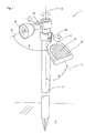
- the lamp 1 shows a solar powered lamp 1, in particular for outdoor use, shown with a post 3 in a floor 2, for example a lawn or a garden bed, is plugged.
- the lamp 1 also has a holder 11, in the direction of the sun aligned a variety of solar cells 4 attached are.
- the solar cells 4 together form a solar cell array 5.
- control electronics In the holder 11 are further not shown control electronics and provided at least one accumulator.
- the solar cells 4 convert the light energy into electrical energy and give it during the day, so during the Conversion process to the accumulator continues, the electrical energy stores.
- the light source 6 and the holder 11 are by means of a respective joint 12 in the attached movably to the upper part of the post 3.
- a respective joint 12 in the attached movably to the upper part of the post 3.
- the joint 12 has a further degree of freedom, so that the Inclination angle of both the light source 6 and the holder 11 relative to the vertical axis 9 of the post 3 can be pivoted.
- the holder 11 and the light source 6 in a ring 13 is pivotable held.
- the ring 13 is in each case via the joint 12 in the same way as that Exemplary embodiment Figure 1 connected to the post 3. It exists the Possibility to form the ring 13 as an outwardly open semicircle, so that this the light beams of the light source 6 as well as the incident on the solar panel 5 Sunbeams are not obstructed.
- the holder 11 ' is spherical and the post 3 has an im Cross-section V-shaped receiving pocket, in which the holder 11 'fixed is used. Between the V-shaped receiving pocket and the post 3 is the Joint 12 provided so that the inclination angle of the holder 11 'from the vertical Axis 9 can be adjusted inclined.
- the spherical holder 11 ' has in its interior an additional, not shown Light source, so that the holder 11 'can be illuminated.
- the holder 11 ' is made of a transparent or transparent material.
- Figure 4 it can be seen that in the circumferential direction of the holder 11 'a Nut 16 is formed on which a bracket 14 surrounds it at two positions. Consequently, the bracket 14 can be moved in the circumferential direction of the holder 11 '. At the same time it is possible, the bracket 14 at its middle position, the light source. 6 is attached, in any angular position about the two pivot points to the To tilt sliding blocks 16.
- the light source. 6 can be aligned independently of the positioning of the solar cell array 5. This significantly increases the efficiency of the solar-powered lamp 1, because the Solar cell array 5 can by adjusting the inclination ⁇ be moved so that the sun's rays more or less perpendicular to the Solar field incident and therefore given during the day a sufficiently large incidence of light is.
- the light source 6 is designed as a radiator, by means of which an exact Lighting a particular object made during the night can be.
- the purpose and the efficiency of the solar powered lamp 1 is therefore significantly improved.
- the holder 11 is formed as a leaf of a flower or a tree.
- the light source 6 may represent a stylized flower of a plant, so that the lamp 1 a causes natural aesthetic effect.
Abstract
Description
Die Erfindung bezieht sich auf eine solarbetriebene Leuchte, insbesondere für den Betrieb im Freien, mit einer Vielzahl von in einem Halter eingesetzten Solarzellen, die ein Solarzellenfeld bilden, und mit mindestens einer mit dem Solarzellenfeld elektrisch verbundenen Lichtquelle.The invention relates to a solar powered lamp, in particular for the Outdoor operation, with a variety of solar cells used in a holder, the form a solar cell array, and at least one with the solar cell array electrically connected light source.
Aus der DE 102 01 816.2 ist der Aufbau und die Funktionsweise einer solarbetriebenen Leuchte zu entnehmen. Die Solarleuchte umfasst hierbei ein zylindrisches Gehäuse, in dessen Deckel eine Vielzahl von Solarzellen, die ein Solarzellenfeld bilden, angeordnet sind. Die Solarzellen sind dabei auf einer Trägerplatte angebracht, auf deren Unterseite, also auf der den Solarzellen gegenüberliegenden Seite, eine Steuerelektronik vorgesehen ist.From DE 102 01 816.2 the structure and operation of a solar powered Remove the light. The solar lamp hereby comprises a cylindrical housing, in the lid of which is arranged a plurality of solar cells, which form a solar cell array are. The solar cells are mounted on a support plate, on the underside, So on the opposite side of the solar cells, an electronic control system is provided.
Des Weiteren sind zwei in das Innere des Gehäuses ragende Leuchtdioden mit der Trägerplatte und der Steuerelektronik elektrisch verbunden, die durch in dem Gehäuse untergebrachten Akkumulatoren mit Strom gespeist werden. Die Steuerelektronik regelt demnach den Betrieb der Solarleuchte, denn die von den Solarzellen umgewandelte Energie des Tageslichtes wird in den Akkumulatoren gespeichert. Sobald durch die Solarzellen nicht mehr genügend Energie umgewandelt werden kann, ändert sich der Betriebszustand der Solarleuchte dahingehend, dass durch die Steuerelektronik die Akkumulatoren mit den Leuchtdioden elektronisch verbunden werden, so dass diese als Lichtquelle dienen.Furthermore, two projecting into the interior of the housing LEDs with the Support plate and the control electronics electrically connected by the in the housing accommodated accumulators are fed with electricity. The control electronics regulates Accordingly, the operation of the solar lamp, because the converted of the solar cells Energy of the daylight is stored in the accumulators. Once through the Solar cells can not be converted enough energy, the changes Operating state of the solar lamp to the effect that by the control electronics Accumulators are connected to the LEDs electronically, so these as Serve light source.
Das Gehäuse der Solarleuchte ist auf einem Stiel oder Pfosten fest angebracht, der beispielsweise in einem Rasenboden einsteckbar ist.The housing of the solar lamp is fixedly mounted on a stick or post, the for example, in a turf floor can be inserted.
Dieser grundsätzliche Aufbau einer Solarleuchte wird nach der DE 100 26 524 derart weitergebildet , dass die Solarzellen in einer geneigt verlaufenden Ebene angeordnet sind. Die gesamte Solarleuchte weist einen säulenförmigen Aufbau auf, in dessen Kopfbereich die Solarzellen untergebracht sind. Der Kopfbereich ist gegenüber dem auf dem Boden aufstehenden Säulenunterteil drehbar. Folglich können die Solarzellen in Richtung der Sonne ausgerichtet werden.This basic structure of a solar lamp is according to DE 100 26 524 such further developed that the solar cells arranged in a sloping plane are. The entire solar lamp has a columnar structure in which Head area, the solar cells are housed. The head area is opposite to the on rotatable bottom pillar base. Consequently, the solar cells in Be aligned towards the sun.
Im Inneren der Säule sind Lichtquellen vorgesehen, die durch die transparent ausgebildete Säulenwand Licht abstrahlen.Inside the pillar light sources are provided, which through the transparent formed column wall radiate light.
Als nachteilig bei dem genannten Stand der Technik hat sich herausgestellt, dass die Solarzellen in Richtung der Sonne nicht optimal ausgerichtet werden können, denn der Säulenkopf mit den Solarzellen kann in seiner Neigung nicht verändert werden. Eine individuelle Einstellung des Lichtkegels gegenüber den Solarzellen kann zwar vorgenommen werden, aber dies ist mit einem erheblichen technischen Aufwand zu bewerkstelligen, denn die Lichtquelle ist im Säuleninneren angeordnet.A disadvantage of the said prior art has been found that the Solar cells in the direction of the sun can not be optimally aligned, because of the Column head with the solar cells can not be changed in its inclination. A individual adjustment of the light cone with respect to the solar cells can indeed but this is a considerable technical effort too accomplish, because the light source is arranged in the column interior.
Es ist daher Aufgabe der Erfindung eine solarbetriebene Leuchte der eingangs genannten Gattung derart weiterzubilden, dass deren Solarzellenfeld optimal in Richtung der Sonneneinstrahlung während des Tagesverlaufes und der jeweiligen Sonnenneigung einstellbar und deren Lichtquelle unabhängig von der Anordnung des Solarzellenfeldes individuell ausrichtbar ist. It is therefore an object of the invention is a solar powered lamp of the beginning mentioned genus such that their solar cell field optimally in Direction of sunlight during the course of the day and the respective Sun tilt adjustable and their light source independent of the arrangement of the Solar cell array is individually aligned.
Diese Aufgabe wird erfindungsgemäß dadurch gelöst, dass der Halter des Solarzellenfeldes und die Lichtquelle als gesonderte Bauteile ausgebildet sind, die unabhängig voneinander einstellbar und/oder ausrichtbar sind.This object is achieved in that the holder of Solar cell array and the light source are designed as separate components, the are independently adjustable and / or alignable.
Es ist besonders zweckmäßig, wenn die Lichtquelle und/oder das Solarzellenfeld des eine Steuerelektronik sowie eine oder mehrere Akkumulatoren aufnehmenden Halters an einem Pfosten, einem Stab oder dergleichen angebracht und wenn die Lichtquelle und/oder der Halter mittels eines Gelenkes an dem Pfosten abgestützt sind.It is particularly useful if the light source and / or the solar cell array of the an electronic control unit and one or more accumulators receiving holder attached to a post, a rod or the like and when the light source and / or the holder are supported by means of a joint on the post.
Um eine individuelle optimale Einstellung der Lichtquelle und des Solarzellenfeldes zu erreichen, ist das Gelenk als Kardangelenk mit mindestens zwei Freiheitsgraden ausgebildet.To an individual optimal adjustment of the light source and the solar panel reach, is the joint as a universal joint with at least two degrees of freedom educated.
Weitere vorteilhafte Weiterbildungen der Erfindung ergeben sich aus den Merkmale der Unteransprüche.Further advantageous developments of the invention will become apparent from the features of Dependent claims.
Dadurch, dass die Lichtquelle und der die Solarzellen aufnehmende Halter als gesonderte Bauteile ausgebildet und über jeweils einen Gelenk mit dem Pfosten der Solarleuchte verbunden sind, können diese Bauteile individuell voneinander aus der horizontalen bzw. der vertikalen Ebene geneigt oder verschwenkt werden. Darüber hinaus ist auch eine Verdrehung dieser Bauteile um die Längsachse der Solarleuchte möglich. Folglich kann das Solarzellenfeld im Laufe des Tages sowie der unterschiedlichen Sonnenstrahleinfallswinkel sowohl in Neigung als auch in seiner Ausrichtung dem Sonnenverlauf nachgefahren werden. Während der Nacht kann die Lichtquelle, die beispielsweise als Strahler ausgebildet ist, auf einen besonders markanten Gegenstand, beispielsweise auf ein Gebüsch oder dergleichen, ausgerichtet werden, um dieses anzustrahlen, und zwar völlig unabhängig von der Positionierung des Solarzellenfeldes.Characterized in that the light source and the solar cell receiving holder as formed separate components and each have a joint with the post of Solar lights are connected, these components can be individually from each other horizontal or the vertical plane inclined or pivoted. About that In addition, a rotation of these components about the longitudinal axis of the solar lamp is possible. Consequently, the solar cell field during the day and the different sun angle incidence angle both in inclination and in his Orientation be traced to the sun. During the night, the Light source, which is for example designed as a spotlight on a particular striking object, for example, on a shrubbery or the like, aligned to illuminate this, completely independent of the positioning of the solar cell field.
In der Zeichnung sind drei erfindungsgemäße Ausführungsbeispiele in perspektivischer Ansicht dargestellt, die nachfolgend näher erläutert werden. Im Einzelnen zeigt:
Figur 1- ein erstes Ausführungsbeispiel der solarbetriebenen Leuchte mit einem die Solarzellen aufnehmenden Halter und einem Strahler,
Figur 2- ein zweites Ausführungsbeispiel einer solarbetriebenen Leuchte mit einem in einem Halter untergebrachten Solarzellenfeld und einer Lichtquelle, die jeweils in einem Ring verschwenkbar gehalten sind,
Figur 3- ein drittes Ausführungsbeispiel einer solarbetriebenen Leuchte mit einem kugelförmigen eine Vielzahl von Solarzellen aufnehmenden Halter, an dem ein Bügel, an dem die Lichtquelle befestigt ist, drehbar und neigbar gehalten ist, und
Figur 4- eine Vergrößerung des dritten Ausführungsbeispieles im Schnitt entlang
der Schnittlinie IV - IV der
Figur 3.
- FIG. 1
- A first embodiment of the solar-powered lamp with a solar cell receiving holder and a spotlight,
- FIG. 2
- A second embodiment of a solar-powered lamp with a solar cell array accommodated in a holder and a light source, which are each held pivotably in a ring,
- FIG. 3
- a third embodiment of a solar-powered lamp with a spherical multi-solar cell receiving holder to which a bracket to which the light source is mounted, is rotatably and tiltably held, and
- FIG. 4
- an enlargement of the third embodiment in section along the section line IV - IV of Figure 3.
In Figur 1 ist eine solarbetriebene Leuchte 1, insbesondere für den Betrieb im Freien,
dargestellt, die mit einem Pfosten 3 in einem Boden 2, beispielsweise einer Rasenfläche
oder einem Gartenbeet, eingesteckt ist. Die Leuchte 1 weist ferner einen Halter 11 auf,
in dem in Richtung der Sonne ausgerichtet eine Vielzahl von Solarzellen 4 befestigt
sind. Die Solarzellen 4 bilden zusammen ein Solarzellenfeld 5.1 shows a solar powered
In dem Halter 11 sind des Weiteren eine nicht dargestellte Steuerelektronik sowie
mindestens ein Akkumulator vorgesehen. Die Solarzellen 4 wandeln die Lichtenergie in
elektrische Energie um und geben diese tagsüber, also während des
Umwandlungsprozesses an den Akkumulator weiter, der die elektrische Energie
speichert.In the
Sobald das Tageslicht nicht mehr ausreichend ist, um elektrische Energie in die
Akkumulatoren abzuführen, wird durch die Steuerelektronik eine elektrische Verbindung
zwischen den Akkumulatoren und einer an dem Pfosten 3 angebrachten Lichtquelle 6
hergestellt, so dass nunmehr die als Strahler ausgebildete Lichtquelle 6 einen
Leuchteffekt erzielt.Once the daylight is no longer sufficient to put electrical energy in the
To dissipate accumulators, is by the control electronics an electrical connection
between the accumulators and a
Die Lichtquelle 6 und der Halter 11 sind mittels jeweils eines Gelenkes 12 in dem
oberen Bereich des Pfostens 3 beweglich befestigt. Zum einen kann nämlich das
Gelenk 12 relativ, also um die vertikale Achse 9 des Pfostens 3, verdreht werden.
Darüber hinaus weist das Gelenk 12 einen weiteren Freiheitsgrad auf, so dass der
Neigungswinkel sowohl der Lichtquelle 6 als auch des Halters 11 gegenüber der
vertikalen Achse 9 des Pfostens 3 verschwenkt werden kann.The
In den Figuren 1 bis 3 ist diese Verschwenkbarkeit bzw. Einstellbarkeit des
Neigungswinkels zwischen den Mittelachsen 7 des Halters 11 und der Mittelachse der
Lichtquelle 6 mit dem Winkel α bzw. β bezeichnet.In Figures 1 to 3, this pivotability or adjustability of
Tilt angle between the
Ferner ist die Beweglichkeit der beiden Gelenke 12 um die vertikale Achse 9 des
Pfostens 3 dargestellt.Furthermore, the mobility of the two
In Figur 2 ist der Halter 11 und die Lichtquelle 6 in einem Ring 13 verschwenkbar
gehalten. Der Ring 13 ist jeweils über das Gelenk 12 in gleicher Weise wie das
Ausführungsbeispiel gem. Figur 1 mit dem Pfosten 3 verbunden. Es besteht die
Möglichkeit, den Ring 13 als nach außen offenen Halbkreis auszubilden, so dass dieser
die Lichtstrahlen der Lichtquelle 6 sowie die auf das Solarzellenfeld 5 auftreffende
Sonnenstrahlen nicht behindert werden.In Figure 2, the
In Figur 3 ist der Halter 11' kugelförmig ausgebildet und der Pfosten 3 weist eine im
Querschnitt V-förmig ausgebildete Aufnahmetasche auf, in der der Halter 11' fest
eingesetzt ist. Zwischen der V-förmigen Aufnahmetasche und dem Pfosten 3 ist das
Gelenk 12 vorgesehen, so dass der Neigungswinkel des Halters 11' aus der vertikalen
Achse 9 geneigt eingestellt werden kann. In Figure 3, the holder 11 'is spherical and the
Der kugelförmige Halter 11' weist in seinem Inneren eine nicht dargestellte zusätzliche Lichtquelle auf, so dass der Halter 11' ausleuchtbar ist. Bei dieser Ausführungsvariante besteht der Halter 11' aus einem transparenten oder ??-transparenten Material.The spherical holder 11 'has in its interior an additional, not shown Light source, so that the holder 11 'can be illuminated. In this embodiment the holder 11 'is made of a transparent or transparent material.
Insbesondere Figur 4 ist zu entnehmen, dass in Umfangsrichtung des Halters 11' ein
Nutenstein 16 angeformt ist, an dem an zwei Positionen ein Bügel 14 diesen umgreift.
Folglich kann der Bügel 14 in Umfangsrichtung des Halters 11' verfahren werden.
Gleichzeitig ist es möglich, den Bügel 14 an dessen mittlerer Position die Lichtquelle 6
angebracht ist, in jede beliebige Winkelposition um die beiden Anlenkpunkte an den
Nutensteinen 16 zu verschwenken.In particular, Figure 4 it can be seen that in the circumferential direction of the holder 11 'a
Allen drei Ausführungsbeispielen ist demnach gemeinsam, dass die Lichtquelle 6
unabhängig von der Positionierung des Solarzellenfeldes 5 ausgerichtet werden kann.
Dies erhöht den Wirkungsgrad der solarbetriebenen Leuchte 1 wesentlich, denn das
Solarzellenfeld 5 kann durch die Einstellung der Neigung α
derart verfahren werden, dass die Sonnenstrahlen mehr oder weniger senkrecht auf das
Solarzellenfeld auftreffen und daher tagsüber ein genügend großer Lichteinfall gegeben
ist.All three embodiments are therefore common that the light source. 6
can be aligned independently of the positioning of the
Darüber hinaus ist die Lichtquelle 6 als Strahler ausgebildet, mittels dem eine exakte
Beleuchtung eines bestimmten Gegenstandes während der Nacht vorgenommen
werden kann.In addition, the
Der Einsatzzweck und der Wirkungsgrad der solarbetriebenen Leuchte 1 ist daher
wesentlich verbessert.The purpose and the efficiency of the solar
Um eine ästhetische Anpassung der Leuchte 1 an den Aufstellungsort zu ermöglichen,
ist der Halter 11 als Blatt einer Blume oder eines Baumes ausgebildet. Die Lichtquelle 6
kann eine stilisierte Blüte einer Pflanze darstellen, so dass die Leuchte 1 einen
natürlichen ästhetischen Wirkungseffekt hervorruft.To allow an aesthetic adaptation of the
Claims (8)
dadurch gekennzeichnet, dass der Halter (11) des Solarzellenfeldes (5) und die Lichtquelle (6) als gesonderte Bauteile ausgebildet sind, die unabhängig voneinander ausrichtbar und/oder einstellbar sind.Solar powered lamp (1), in particular for outdoor use, having a multiplicity of solar cells (4) used in a holder (11) forming a solar cell array (5) and at least one light source electrically connected to the solar cell array (5) (6)
characterized in that the holder (11) of the solar cell array (5) and the light source (6) are formed as separate components which are independently alignable and / or adjustable.
dadurch gekennzeichnet, dass die Lichtquelle (6) und/ oder der das Solarzellenfeld (5), eine Steuerelektronik sowie einen oder mehreren Akkumulatoren aufnehmende Halter (11) an einem Pfosten (3), einem Stab oder dgl. angebracht sind und dass die Lichtquelle (6) und/oder der Halter (11) mittels eines Gelenkes (12) an dem Pfosten (3) abgestützt sind.Luminaire according to claim 1,
characterized in that the light source (6) and / or the solar cell array (5), an electronic control unit and one or more accumulators receiving holder (11) on a post (3), a rod or the like are mounted and that the light source ( 6) and / or the holder (11) by means of a joint (12) on the post (3) are supported.
dadurch gekennzeichnet, dass das Gelenk (12) als Kardangelenk mit mindestens zwei Freiheitsgraden ausgebildet ist.Luminaire according to claim 2,
characterized in that the joint (12) is designed as a universal joint with at least two degrees of freedom.
dadurch gekennzeichnet, dass der Halter (11) und/oder die Lichtquelle (6) in einem Ring (13), der relativ zu dem Pfosten (3) drehbar ist, gehalten sind.Luminaire according to claim 2 or 3,
characterized in that the holder (11) and / or the light source (6) are held in a ring (13) which is rotatable relative to the post (3).
dadurch gekennzeichnet, dass die Lichtquelle (6) in einem Bügel (14) angeordnet ist und dass der Bügel (14) drehbar und/oder neigbar an dem Halter (11) abgestützt ist.Luminaire according to one or more of claims 1 to 4,
characterized in that the light source (6) is arranged in a bracket (14) and that the bracket (14) is rotatably and / or tiltably supported on the holder (11).
dadurch gekennzeichnet, dass der Halter (11) als Blatt einer Blume, eines Baumes oder dgl. gestaltet ist. Luminaire according to one or more of the preceding claims,
characterized in that the holder (11) is designed as a leaf of a flower, a tree or the like.
dadurch gekennzeichnet, dass die Lichtquelle (6) als Strahler ausgebildet ist.Luminaire according to one or more of the preceding claims,
characterized in that the light source (6) is designed as a radiator.
dadurch gekennzeichnet, dass mehrere Solarzellenfelder (5) vorgesehen sind, die in voneinander getrennten Halter (11) befestigt sind.Luminaire according to one or more of the preceding claims,
characterized in that a plurality of solar cell panels (5) are provided, which are fixed in separate holders (11).
Applications Claiming Priority (2)
| Application Number | Priority Date | Filing Date | Title |
|---|---|---|---|
| DE20311585U | 2003-07-25 | ||
| DE20311585U DE20311585U1 (en) | 2003-07-25 | 2003-07-25 | Solar powered lamp |
Publications (2)
| Publication Number | Publication Date |
|---|---|
| EP1500870A1 true EP1500870A1 (en) | 2005-01-26 |
| EP1500870B1 EP1500870B1 (en) | 2006-08-30 |
Family
ID=29225427
Family Applications (1)
| Application Number | Title | Priority Date | Filing Date |
|---|---|---|---|
| EP04012171A Active EP1500870B1 (en) | 2003-07-25 | 2004-05-22 | Solar powered lamp |
Country Status (3)
| Country | Link |
|---|---|
| EP (1) | EP1500870B1 (en) |
| AT (1) | ATE338245T1 (en) |
| DE (2) | DE20311585U1 (en) |
Cited By (10)
| Publication number | Priority date | Publication date | Assignee | Title |
|---|---|---|---|---|
| WO2010122179A1 (en) * | 2009-04-20 | 2010-10-28 | Siarq, S.L. | Lighting system with a photovoltaic power supply and a light intensity which can be programmed and controlled in situ or remotely |
| US7891832B2 (en) | 2005-05-18 | 2011-02-22 | Allsop, Inc. | Outdoor light with positionable solar collector |
| EP2638319A2 (en) * | 2010-11-13 | 2013-09-18 | Stephen Katsaros | Adjustable solar charged lamp |
| WO2016119203A1 (en) * | 2015-01-30 | 2016-08-04 | 凯灿贸易(深圳)有限公司 | Solar laser lamp |
| GR20160100153A (en) * | 2016-04-12 | 2017-11-30 | Ειρηνη Ευαγγελου Παπαδακη | Self-powered lighting body |
| US9839088B1 (en) | 2016-03-10 | 2017-12-05 | Heathco, Llc | Security light with remote photo-voltaic module and battery backup and related methods |
| EP3255335A4 (en) * | 2015-02-05 | 2018-01-03 | Alessandro Caviasca | Photovoltaic module |
| CN110864260A (en) * | 2019-12-04 | 2020-03-06 | 深圳市若盛科技有限公司 | High-practicability solar lamp |
| US10718500B1 (en) | 2019-08-30 | 2020-07-21 | HealthCo LLC | Solar powered security light with variable mounting |
| US20230358377A1 (en) * | 2022-03-31 | 2023-11-09 | Alliance Sports Group | Outdoor Lighting Apparatus |
Families Citing this family (10)
| Publication number | Priority date | Publication date | Assignee | Title |
|---|---|---|---|---|
| WO2005114043A1 (en) * | 2004-05-14 | 2005-12-01 | Allsop, Inc. | Offset solar-powered outdoor lighting apparatus |
| ITPD20040198A1 (en) * | 2004-07-23 | 2004-10-23 | Lino Manfrotto & Co Spa | SUPPORT FOR ELECTRONIC EQUIPMENT, ESPECIALLY OF PHOTOGRAPHIC VIDEO TYPE |
| GB0512984D0 (en) * | 2005-06-27 | 2005-08-03 | Bu Innovations Ltd | Pickable solar powered light |
| DE102007013129A1 (en) * | 2007-03-15 | 2008-09-25 | Stadtfeld Elektrotechnische Fabrik Gmbh & Co. Kg | Lighting device i.e. network-independent lighting device, for e.g. road, has energy storage provided for storage of produced electrical energy, where solar unit and lighting unit are aligned independent of each other |
| DE102007045119A1 (en) * | 2007-09-20 | 2009-04-02 | Trilux Gmbh & Co. Kg | Outdoor light fixture, particularly for use in public area, has housing with photometric aggregates and lamp fixture, and translucent light well is connected with housing in sealing manner |
| DE202012100891U1 (en) * | 2012-03-13 | 2013-06-14 | Steinel Gmbh | A lighting device |
| BE1024073B1 (en) * | 2015-12-23 | 2017-11-10 | Rik Hiergens | LIGHTING FOR USE IN A GARDEN OR IN A VEGETABLE ENVIRONMENT OR THE LIKE. |
| CN106678612A (en) * | 2016-11-10 | 2017-05-17 | 成都朵猫文化传播有限公司 | Gardening lamp |
| DE102018000677A1 (en) | 2018-01-18 | 2019-07-18 | Ronotic Ag | solar light |
| DE202018000444U1 (en) | 2018-01-18 | 2018-02-22 | Ronotic Ag | solar light |
Citations (8)
| Publication number | Priority date | Publication date | Assignee | Title |
|---|---|---|---|---|
| US4486820A (en) * | 1980-07-16 | 1984-12-04 | Kyoto Ceramic Company Limited | Lighting equipment with a solar cell |
| US4977488A (en) * | 1990-03-14 | 1990-12-11 | Australux North America Ltd. | Solar powered outdoor recreational light with positionable solar panel |
| DE29521271U1 (en) * | 1995-05-03 | 1996-11-21 | Kaempf Hartmut | Self-sufficient lighting device for extensive advertising media |
| DE29920735U1 (en) * | 1999-11-26 | 2000-05-25 | Trisl Klaus | KT solar panel carrier with gimbal suspension |
| US6107941A (en) * | 1991-10-09 | 2000-08-22 | R. D. Jones, Right Of Way, Inc. | Traffic control system and kit |
| DE10026524A1 (en) | 2000-05-27 | 2001-12-06 | Solar Trend Gmbh | Solar lighting unit for providing illumination, has pillar with rotary head unit |
| EP1178261A2 (en) * | 2000-07-31 | 2002-02-06 | Rudolf Zimmermann GmbH & Co. KG. | Solar light having a substantially spherical, at least partially light pervious body |
| DE10201816A1 (en) | 2002-01-18 | 2003-07-31 | Wagner Gmbh J | Device for converting solar energy into electric power for a lighting unit has a support plate and solar cells set in rows and fastened on the support plate. |
-
2003
- 2003-07-25 DE DE20311585U patent/DE20311585U1/en not_active Expired - Lifetime
-
2004
- 2004-05-22 DE DE502004001313T patent/DE502004001313D1/en not_active Expired - Fee Related
- 2004-05-22 AT AT04012171T patent/ATE338245T1/en not_active IP Right Cessation
- 2004-05-22 EP EP04012171A patent/EP1500870B1/en active Active
Patent Citations (8)
| Publication number | Priority date | Publication date | Assignee | Title |
|---|---|---|---|---|
| US4486820A (en) * | 1980-07-16 | 1984-12-04 | Kyoto Ceramic Company Limited | Lighting equipment with a solar cell |
| US4977488A (en) * | 1990-03-14 | 1990-12-11 | Australux North America Ltd. | Solar powered outdoor recreational light with positionable solar panel |
| US6107941A (en) * | 1991-10-09 | 2000-08-22 | R. D. Jones, Right Of Way, Inc. | Traffic control system and kit |
| DE29521271U1 (en) * | 1995-05-03 | 1996-11-21 | Kaempf Hartmut | Self-sufficient lighting device for extensive advertising media |
| DE29920735U1 (en) * | 1999-11-26 | 2000-05-25 | Trisl Klaus | KT solar panel carrier with gimbal suspension |
| DE10026524A1 (en) | 2000-05-27 | 2001-12-06 | Solar Trend Gmbh | Solar lighting unit for providing illumination, has pillar with rotary head unit |
| EP1178261A2 (en) * | 2000-07-31 | 2002-02-06 | Rudolf Zimmermann GmbH & Co. KG. | Solar light having a substantially spherical, at least partially light pervious body |
| DE10201816A1 (en) | 2002-01-18 | 2003-07-31 | Wagner Gmbh J | Device for converting solar energy into electric power for a lighting unit has a support plate and solar cells set in rows and fastened on the support plate. |
Cited By (17)
| Publication number | Priority date | Publication date | Assignee | Title |
|---|---|---|---|---|
| US7891832B2 (en) | 2005-05-18 | 2011-02-22 | Allsop, Inc. | Outdoor light with positionable solar collector |
| WO2010122179A1 (en) * | 2009-04-20 | 2010-10-28 | Siarq, S.L. | Lighting system with a photovoltaic power supply and a light intensity which can be programmed and controlled in situ or remotely |
| US10234083B2 (en) | 2010-11-13 | 2019-03-19 | Stephen Katsaros | Adjustable solar charged lamp |
| EP2638319A2 (en) * | 2010-11-13 | 2013-09-18 | Stephen Katsaros | Adjustable solar charged lamp |
| EP2638319A4 (en) * | 2010-11-13 | 2014-12-17 | Stephen Katsaros | Adjustable solar charged lamp |
| US9200767B2 (en) | 2010-11-13 | 2015-12-01 | Stephen Katsaros | Adjustable solar charged lamp |
| US9429281B2 (en) | 2010-11-13 | 2016-08-30 | Stephen Katsaros | Adjustable solar charged lamp |
| AP3786A (en) * | 2010-11-13 | 2016-08-31 | Stephen Katsaros | Adjustable solar charged lamp |
| WO2016119203A1 (en) * | 2015-01-30 | 2016-08-04 | 凯灿贸易(深圳)有限公司 | Solar laser lamp |
| EP3255335A4 (en) * | 2015-02-05 | 2018-01-03 | Alessandro Caviasca | Photovoltaic module |
| US9839088B1 (en) | 2016-03-10 | 2017-12-05 | Heathco, Llc | Security light with remote photo-voltaic module and battery backup and related methods |
| GR20160100153A (en) * | 2016-04-12 | 2017-11-30 | Ειρηνη Ευαγγελου Παπαδακη | Self-powered lighting body |
| US10718500B1 (en) | 2019-08-30 | 2020-07-21 | HealthCo LLC | Solar powered security light with variable mounting |
| US11073267B1 (en) | 2019-08-30 | 2021-07-27 | Heathco Llc | Solar powered security light with variable mounting |
| CN110864260A (en) * | 2019-12-04 | 2020-03-06 | 深圳市若盛科技有限公司 | High-practicability solar lamp |
| US20230358377A1 (en) * | 2022-03-31 | 2023-11-09 | Alliance Sports Group | Outdoor Lighting Apparatus |
| US11906133B2 (en) * | 2022-03-31 | 2024-02-20 | Alliance Sports Group, L.P. | Outdoor lighting apparatus |
Also Published As
| Publication number | Publication date |
|---|---|
| EP1500870B1 (en) | 2006-08-30 |
| DE502004001313D1 (en) | 2006-10-12 |
| DE20311585U1 (en) | 2003-10-09 |
| ATE338245T1 (en) | 2006-09-15 |
Similar Documents
| Publication | Publication Date | Title |
|---|---|---|
| EP1500870B1 (en) | Solar powered lamp | |
| EP1514060B1 (en) | Device that automatically tracks the position of the sun | |
| DE102006022982B4 (en) | Device for mounting at least one solar module for at least uniaxial tracking | |
| DE102005033777A1 (en) | Roofing with lighting device | |
| EP2166277A1 (en) | Illumination device | |
| DE102006010781A1 (en) | Sun position tracking device for e.g. photovoltaic module, has driving motor for pivoting solar module around axis and elevation axis, where axes are driven, such that elevation axis is guided with respect to its inclination | |
| DE102005046874A1 (en) | Device for receiving and tracking solar collector modules | |
| DE102004013590B4 (en) | Solar concentrator with several mirrors | |
| DE10192244B4 (en) | Sun position follower for solar collectors, absorbers, reflectors, or photovoltaic modules | |
| DE102018002190A1 (en) | mast lights | |
| DE10037237C2 (en) | Solar lamp with an essentially spherical, at least partially translucent lamp body | |
| DE4020032C2 (en) | Device for converting solar energy into electricity, in particular for recharging the batteries of electrically powered vehicles | |
| EP2639502B1 (en) | Light device | |
| DE10129478C2 (en) | Solar module / consumer unit | |
| DE102013005441A1 (en) | Solar plant for being located on building roof for producing electrical energy, has solar element turned away from solar element pair, connected to another solar element in common groove and occupying angle that lies in specific range | |
| DE102018006506B4 (en) | Luminaire for work, film or sporting events | |
| DE19928857C2 (en) | Dual-axis trackable solar cell arrangement | |
| WO2009112026A1 (en) | Solar module carrier (tracker) | |
| DE102011103170A1 (en) | Solar device with reflector device and reflector device | |
| DE102018000677A1 (en) | solar light | |
| CN216492371U (en) | Portable shading canopy of gardens seedling planting usefulness | |
| DE202018000444U1 (en) | solar light | |
| DE10045028A1 (en) | Illumination system for simulating sunlight has lights that can be controlled separately as light rows and adjusted in intensity while maintaining wavelength spectrum (mechanical dimming) | |
| DE10026524A1 (en) | Solar lighting unit for providing illumination, has pillar with rotary head unit | |
| EP1517082A2 (en) | Decorative lamp |
Legal Events
| Date | Code | Title | Description |
|---|---|---|---|
| PUAI | Public reference made under article 153(3) epc to a published international application that has entered the european phase |
Free format text: ORIGINAL CODE: 0009012 |
|
| AK | Designated contracting states |
Kind code of ref document: A1 Designated state(s): AT BE BG CH CY CZ DE DK EE ES FI FR GB GR HU IE IT LI LU MC NL PL PT RO SE SI SK TR |
|
| AX | Request for extension of the european patent |
Extension state: AL HR LT LV MK |
|
| 17P | Request for examination filed |
Effective date: 20050709 |
|
| AKX | Designation fees paid |
Designated state(s): AT BE BG CH CY CZ DE DK EE ES FI FR GB GR HU IE IT LI LU MC NL PL PT RO SE SI SK TR |
|
| GRAP | Despatch of communication of intention to grant a patent |
Free format text: ORIGINAL CODE: EPIDOSNIGR1 |
|
| GRAS | Grant fee paid |
Free format text: ORIGINAL CODE: EPIDOSNIGR3 |
|
| GRAA | (expected) grant |
Free format text: ORIGINAL CODE: 0009210 |
|
| AK | Designated contracting states |
Kind code of ref document: B1 Designated state(s): AT BE BG CH CY CZ DE DK EE ES FI FR GB GR HU IE IT LI LU MC NL PL PT RO SE SI SK TR |
|
| PG25 | Lapsed in a contracting state [announced via postgrant information from national office to epo] |
Ref country code: IT Free format text: LAPSE BECAUSE OF FAILURE TO SUBMIT A TRANSLATION OF THE DESCRIPTION OR TO PAY THE FEE WITHIN THE PRESCRIBED TIME-LIMIT;WARNING: LAPSES OF ITALIAN PATENTS WITH EFFECTIVE DATE BEFORE 2007 MAY HAVE OCCURRED AT ANY TIME BEFORE 2007. THE CORRECT EFFECTIVE DATE MAY BE DIFFERENT FROM THE ONE RECORDED. Effective date: 20060830 Ref country code: NL Free format text: LAPSE BECAUSE OF FAILURE TO SUBMIT A TRANSLATION OF THE DESCRIPTION OR TO PAY THE FEE WITHIN THE PRESCRIBED TIME-LIMIT Effective date: 20060830 Ref country code: IE Free format text: LAPSE BECAUSE OF FAILURE TO SUBMIT A TRANSLATION OF THE DESCRIPTION OR TO PAY THE FEE WITHIN THE PRESCRIBED TIME-LIMIT Effective date: 20060830 Ref country code: PL Free format text: LAPSE BECAUSE OF FAILURE TO SUBMIT A TRANSLATION OF THE DESCRIPTION OR TO PAY THE FEE WITHIN THE PRESCRIBED TIME-LIMIT Effective date: 20060830 Ref country code: RO Free format text: LAPSE BECAUSE OF FAILURE TO SUBMIT A TRANSLATION OF THE DESCRIPTION OR TO PAY THE FEE WITHIN THE PRESCRIBED TIME-LIMIT Effective date: 20060830 Ref country code: SK Free format text: LAPSE BECAUSE OF FAILURE TO SUBMIT A TRANSLATION OF THE DESCRIPTION OR TO PAY THE FEE WITHIN THE PRESCRIBED TIME-LIMIT Effective date: 20060830 Ref country code: SI Free format text: LAPSE BECAUSE OF FAILURE TO SUBMIT A TRANSLATION OF THE DESCRIPTION OR TO PAY THE FEE WITHIN THE PRESCRIBED TIME-LIMIT Effective date: 20060830 Ref country code: FI Free format text: LAPSE BECAUSE OF FAILURE TO SUBMIT A TRANSLATION OF THE DESCRIPTION OR TO PAY THE FEE WITHIN THE PRESCRIBED TIME-LIMIT Effective date: 20060830 Ref country code: CZ Free format text: LAPSE BECAUSE OF FAILURE TO SUBMIT A TRANSLATION OF THE DESCRIPTION OR TO PAY THE FEE WITHIN THE PRESCRIBED TIME-LIMIT Effective date: 20060830 Ref country code: GB Free format text: LAPSE BECAUSE OF FAILURE TO SUBMIT A TRANSLATION OF THE DESCRIPTION OR TO PAY THE FEE WITHIN THE PRESCRIBED TIME-LIMIT Effective date: 20060830 |
|
| REG | Reference to a national code |
Ref country code: GB Ref legal event code: FG4D Free format text: NOT ENGLISH |
|
| REG | Reference to a national code |
Ref country code: CH Ref legal event code: EP |
|
| REG | Reference to a national code |
Ref country code: IE Ref legal event code: FG4D Free format text: LANGUAGE OF EP DOCUMENT: GERMAN |
|
| REF | Corresponds to: |
Ref document number: 502004001313 Country of ref document: DE Date of ref document: 20061012 Kind code of ref document: P |
|
| PG25 | Lapsed in a contracting state [announced via postgrant information from national office to epo] |
Ref country code: SE Free format text: LAPSE BECAUSE OF FAILURE TO SUBMIT A TRANSLATION OF THE DESCRIPTION OR TO PAY THE FEE WITHIN THE PRESCRIBED TIME-LIMIT Effective date: 20061130 Ref country code: DK Free format text: LAPSE BECAUSE OF FAILURE TO SUBMIT A TRANSLATION OF THE DESCRIPTION OR TO PAY THE FEE WITHIN THE PRESCRIBED TIME-LIMIT Effective date: 20061130 Ref country code: BG Free format text: LAPSE BECAUSE OF FAILURE TO SUBMIT A TRANSLATION OF THE DESCRIPTION OR TO PAY THE FEE WITHIN THE PRESCRIBED TIME-LIMIT Effective date: 20061130 |
|
| PG25 | Lapsed in a contracting state [announced via postgrant information from national office to epo] |
Ref country code: ES Free format text: LAPSE BECAUSE OF FAILURE TO SUBMIT A TRANSLATION OF THE DESCRIPTION OR TO PAY THE FEE WITHIN THE PRESCRIBED TIME-LIMIT Effective date: 20061211 |
|
| PG25 | Lapsed in a contracting state [announced via postgrant information from national office to epo] |
Ref country code: PT Free format text: LAPSE BECAUSE OF FAILURE TO SUBMIT A TRANSLATION OF THE DESCRIPTION OR TO PAY THE FEE WITHIN THE PRESCRIBED TIME-LIMIT Effective date: 20070206 |
|
| NLV1 | Nl: lapsed or annulled due to failure to fulfill the requirements of art. 29p and 29m of the patents act | ||
| GBV | Gb: ep patent (uk) treated as always having been void in accordance with gb section 77(7)/1977 [no translation filed] |
Effective date: 20060830 |
|
| REG | Reference to a national code |
Ref country code: IE Ref legal event code: FD4D |
|
| EN | Fr: translation not filed | ||
| PLBE | No opposition filed within time limit |
Free format text: ORIGINAL CODE: 0009261 |
|
| STAA | Information on the status of an ep patent application or granted ep patent |
Free format text: STATUS: NO OPPOSITION FILED WITHIN TIME LIMIT |
|
| 26N | No opposition filed |
Effective date: 20070531 |
|
| BERE | Be: lapsed |
Owner name: J. WAGNER G.M.B.H. Effective date: 20070531 |
|
| PG25 | Lapsed in a contracting state [announced via postgrant information from national office to epo] |
Ref country code: MC Free format text: LAPSE BECAUSE OF NON-PAYMENT OF DUE FEES Effective date: 20070531 |
|
| PG25 | Lapsed in a contracting state [announced via postgrant information from national office to epo] |
Ref country code: BE Free format text: LAPSE BECAUSE OF NON-PAYMENT OF DUE FEES Effective date: 20070531 |
|
| PG25 | Lapsed in a contracting state [announced via postgrant information from national office to epo] |
Ref country code: GR Free format text: LAPSE BECAUSE OF FAILURE TO SUBMIT A TRANSLATION OF THE DESCRIPTION OR TO PAY THE FEE WITHIN THE PRESCRIBED TIME-LIMIT Effective date: 20061201 Ref country code: FR Free format text: LAPSE BECAUSE OF FAILURE TO SUBMIT A TRANSLATION OF THE DESCRIPTION OR TO PAY THE FEE WITHIN THE PRESCRIBED TIME-LIMIT Effective date: 20070511 |
|
| PG25 | Lapsed in a contracting state [announced via postgrant information from national office to epo] |
Ref country code: EE Free format text: LAPSE BECAUSE OF FAILURE TO SUBMIT A TRANSLATION OF THE DESCRIPTION OR TO PAY THE FEE WITHIN THE PRESCRIBED TIME-LIMIT Effective date: 20060830 |
|
| PGFP | Annual fee paid to national office [announced via postgrant information from national office to epo] |
Ref country code: AT Payment date: 20080521 Year of fee payment: 5 |
|
| PG25 | Lapsed in a contracting state [announced via postgrant information from national office to epo] |
Ref country code: FR Free format text: LAPSE BECAUSE OF FAILURE TO SUBMIT A TRANSLATION OF THE DESCRIPTION OR TO PAY THE FEE WITHIN THE PRESCRIBED TIME-LIMIT Effective date: 20060830 |
|
| PG25 | Lapsed in a contracting state [announced via postgrant information from national office to epo] |
Ref country code: LU Free format text: LAPSE BECAUSE OF NON-PAYMENT OF DUE FEES Effective date: 20070522 Ref country code: CY Free format text: LAPSE BECAUSE OF FAILURE TO SUBMIT A TRANSLATION OF THE DESCRIPTION OR TO PAY THE FEE WITHIN THE PRESCRIBED TIME-LIMIT Effective date: 20060830 |
|
| PG25 | Lapsed in a contracting state [announced via postgrant information from national office to epo] |
Ref country code: TR Free format text: LAPSE BECAUSE OF FAILURE TO SUBMIT A TRANSLATION OF THE DESCRIPTION OR TO PAY THE FEE WITHIN THE PRESCRIBED TIME-LIMIT Effective date: 20060830 Ref country code: HU Free format text: LAPSE BECAUSE OF FAILURE TO SUBMIT A TRANSLATION OF THE DESCRIPTION OR TO PAY THE FEE WITHIN THE PRESCRIBED TIME-LIMIT Effective date: 20070301 |
|
| PGFP | Annual fee paid to national office [announced via postgrant information from national office to epo] |
Ref country code: CH Payment date: 20090515 Year of fee payment: 6 |
|
| PGFP | Annual fee paid to national office [announced via postgrant information from national office to epo] |
Ref country code: DE Payment date: 20090625 Year of fee payment: 6 |
|
| PG25 | Lapsed in a contracting state [announced via postgrant information from national office to epo] |
Ref country code: AT Free format text: LAPSE BECAUSE OF NON-PAYMENT OF DUE FEES Effective date: 20090522 |
|
| REG | Reference to a national code |
Ref country code: CH Ref legal event code: PL |
|
| PG25 | Lapsed in a contracting state [announced via postgrant information from national office to epo] |
Ref country code: CH Free format text: LAPSE BECAUSE OF NON-PAYMENT OF DUE FEES Effective date: 20100531 Ref country code: LI Free format text: LAPSE BECAUSE OF NON-PAYMENT OF DUE FEES Effective date: 20100531 |
|
| PG25 | Lapsed in a contracting state [announced via postgrant information from national office to epo] |
Ref country code: DE Free format text: LAPSE BECAUSE OF NON-PAYMENT OF DUE FEES Effective date: 20101201 |