EP1503582A1 - Video signal conversion apparatus - Google Patents
Video signal conversion apparatus Download PDFInfo
- Publication number
- EP1503582A1 EP1503582A1 EP04017354A EP04017354A EP1503582A1 EP 1503582 A1 EP1503582 A1 EP 1503582A1 EP 04017354 A EP04017354 A EP 04017354A EP 04017354 A EP04017354 A EP 04017354A EP 1503582 A1 EP1503582 A1 EP 1503582A1
- Authority
- EP
- European Patent Office
- Prior art keywords
- video signal
- signal
- progressive
- frame rate
- input
- Prior art date
- Legal status (The legal status is an assumption and is not a legal conclusion. Google has not performed a legal analysis and makes no representation as to the accuracy of the status listed.)
- Withdrawn
Links
Images
Classifications
-
- H—ELECTRICITY
- H04—ELECTRIC COMMUNICATION TECHNIQUE
- H04N—PICTORIAL COMMUNICATION, e.g. TELEVISION
- H04N7/00—Television systems
- H04N7/01—Conversion of standards, e.g. involving analogue television standards or digital television standards processed at pixel level
- H04N7/0112—Conversion of standards, e.g. involving analogue television standards or digital television standards processed at pixel level one of the standards corresponding to a cinematograph film standard
-
- H—ELECTRICITY
- H04—ELECTRIC COMMUNICATION TECHNIQUE
- H04N—PICTORIAL COMMUNICATION, e.g. TELEVISION
- H04N7/00—Television systems
- H04N7/01—Conversion of standards, e.g. involving analogue television standards or digital television standards processed at pixel level
- H04N7/0117—Conversion of standards, e.g. involving analogue television standards or digital television standards processed at pixel level involving conversion of the spatial resolution of the incoming video signal
- H04N7/012—Conversion between an interlaced and a progressive signal
-
- H—ELECTRICITY
- H04—ELECTRIC COMMUNICATION TECHNIQUE
- H04N—PICTORIAL COMMUNICATION, e.g. TELEVISION
- H04N7/00—Television systems
- H04N7/01—Conversion of standards, e.g. involving analogue television standards or digital television standards processed at pixel level
- H04N7/0127—Conversion of standards, e.g. involving analogue television standards or digital television standards processed at pixel level by changing the field or frame frequency of the incoming video signal, e.g. frame rate converter
- H04N7/0132—Conversion of standards, e.g. involving analogue television standards or digital television standards processed at pixel level by changing the field or frame frequency of the incoming video signal, e.g. frame rate converter the field or frame frequency of the incoming video signal being multiplied by a positive integer, e.g. for flicker reduction
Definitions
- the present invention relates to a video signal conversion apparatus which converts an input video signal so as to be displayable on a display apparatus with a high picture quality.
- Video signals of film source based on movies or films are often contained in video signals of standard television systems such as the NTSC format.
- the movie or film consists of 24 frames per second.
- the video signal of the standard television system consists of 30 frames per second, and it is a video signal of interlaced scanning in which one frame is constituted by 2 fields. Since the numbers of frames per second are different, the frames of the movie or film are usually subjected to television-cinema conversion by a 2-3 pulldown scheme so as to obtain the video signal of the standard television system.
- the first and second fields of the first frame of the video signal are created from the first frame of the movie or film, the first and second fields of the second frame and the first field of the third frame of the video signal from the second frame, and the second field of the third frame and the first field of the fourth frame of the video signal from the third frame.
- the video signal is created for 2 fields, for 3 fields, for 2 fields, for 3 fields, ⁇ from the successive frames of the film by similar conversion steps.
- the movie or film is converted into that video signal of the standard television system in which the 2 frames of the former correspond to the 5 frames of the latter, and in which the video signal of 2 fields and the video signal of 3 fields are alternately repeated in correspondence with the frames of the movie or film.
- the above-mentioned third frame for example, in the successive frames of the video signal is formed of the combination between the pictures of the second frame and third frame of the movie or film.
- the present invention is intended to solve the above problem mentioned by way of example, and it has for its object to provide a video signal conversion apparatus which can enhance display qualities for video signals of both the film source and the video source.
- a video signal conversion apparatus consists in a video signal conversion apparatus wherein an input video signal is converted into a progressive video signal of predetermined frame rate, characterized by comprising a film source discrimination means for discriminating whether or not the input video signal is a video signal of film source as based on a film; an interlace/progressive conversion means for converting which, when the input video signal is an interlaced video signal, the input video signal into the progressive video signal by a conversion method conforming to a result of the discrimination by said film source discrimination means and then outputs the progressive video signal, and for outputting, when the input video signal is not the interlaced video signal, the input video signal as it is; a frame rate conversion means for converting the output video signal of said interlace/progressive conversion means into a video signal of higher frame rate in accordance with the result of the discrimination by said film source discrimination means; an input signal discrimination means which discriminates a sort and a signal supply source of the input video signal; an operation mode setting means for setting
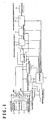
- Fig. 1 shows a video signal conversion apparatus according to the present invention.
- the video signal conversion apparatus includes an input signal selection circuit 1, a signal sort discriminator 2, a setting data memory 3, a controller 4, a pulldown detector 5, an I/P (interlace/progressive) converter 6, a changeover switch 7, a picture quality adjustment circuit 8, a frame rate converter 9 and a PDP driving sequence generation circuit 10.
- the video signal conversion apparatus has video signal input terminals INV1 - INV4, external flag input terminals INF1 - INF4, and changeover switches SW1 and SW2.
- Signal supply sources are connected to the respective video signal input terminals INV1 - INV4, and video signals are supplied from the signal supply sources.
- a receiving tuner 11 for a ground wave broadcast, a video tape recorder (VTR) 12, a DVD player 13 and a receiving tuner 14 for a digital broadcast are employed as the signal supply sources.
- the video signal output terminals of the signal supply sources 11 - 14 are connected to the video signal input terminals INV1 - INV4 in the order mentioned.
- the receiving tuner 14 for the digital broadcast is provided with a flag output terminal, which is connected to the external flag input terminal INF4.
- the external flag input terminals, for example, INF1 - INF3 which correspond to the signal supply sources having no flag output terminals are held open.
- the receiving tuner 14 delivers from the flag output terminal, an Mpeg flag which indicates whether or not the video signal being outputted is a video signal of film source based on a film.
- the output video signals of the respective signal supply sources 11 - 14 are all digital signals.
- the receiving tuner 11 for the ground wave broadcast and the video tape recorder 12 output video signals of NTSC format, respectively.
- the DVD player 13 outputs an interlaced video signal or a progressive video signal which has 480 scanning lines.
- the receiving tuner 14 for the digital broadcast outputs any of an interlaced video signal having 480 scanning lines, a progressive video signal having 480 scanning lines, a progressive video signal having 720 scanning lines, and an interlaced video signal having 1080 scanning lines.
- Each of the changeover switches SW1 and SW2 is a switch which has four stationary contacts, and in which any of the stationary contacts is selectively connected by a movable contact in accordance with a selection command signal from the input signal selection circuit 1.
- the video signal input terminals INV1 - INV4 are respectively connected to the stationary contacts of the changeover switch SW1.
- the external flag input terminals INF1 - INF4 are respectively connected to the stationary contacts of the changeover switch SW2.
- the changeover switch SW1 relays and supplies the video signal supplied to the selected and connected stationary contact, to the signal sort discriminator 2, pulldown detector 5 and I/P converter 6.
- the changeover switch SW2 relays and supplies the flag supplied to the selected and connected stationary terminal, to the pulldown detector 5.
- the input signal selection circuit 1 includes an operating portion not shown, and it outputs to the changeover switches SW1 and SW2, the selection command signals for changing-over the selected positions of these changeover switches SW1 and SW2 in accordance with the user's operations of the operating portion. Besides, the input signal selection circuit 1 supplies the setting data memory 3 and the controller 4 with signal supply source data which indicates the input terminal currently under selection (any of "ground wave broadcast”, “VTR”, “DVD” and "digital broadcast”). Incidentally, since the corresponding relations between the input terminals INV1 - INV4 and the signal supply sources 11 - 14 are fixed, the signal supply source data which indicates the input terminal currently under selection is obtained in correspondence with the selected position of the changeover switch SW1.
- the signal sort discriminator 2 discriminates the sort of the video signal selected and relayed by the changeover switch SW1.
- the sorts of video signals are divided into standard video signals (CVBS) such as the video signal of NTSC format, and the other video signals. Further, the other video signals are divided depending upon the number of scanning lines, and interlace/non-interlace.
- Signal sort data which indicates a result discriminated by the signal sort discriminator 2, is supplied to the setting data memory 3 and the controller 4.
- the input signal selection circuit 1 and the signal sort discriminator 2 constitute input signal discrimination means.
- the setting data memory 3 is operation mode setting means. Setting data which indicate operation modes in the individual sorts of the video signals of the respective signal supply sources, are written in the setting data memory 3 beforehand.
- the setting data determine the respective control states of the pulldown detector 5, I/P converter 6, changeover switch 7, picture quality adjustment circuit 8, frame rate converter 9 and PDP driving sequence generation circuit 10 based on the controller 5.
- the setting data is read out from a storage location specified in accordance with the signal supply source data from the input signal selection circuit 1 and the signal sort data from the signal sort discriminator 2, by the controller 4.
- the setting data is any of "on", "off” and "advanced”.
- the controller 4 may well designate the storage location of the setting data memory 3 in accordance with the signal supply source data from the input signal selection circuit 1 and the signal sort data from the signal sort discriminator 2, so as to read out the setting data from the designated storage location.
- the controller 4 is control means, and it generates various instructions for controlling the respective operations of the pulldown detector 5, I/P converter 6, changeover switch 7, picture quality adjustment circuit 8, frame rate converter 9 and PDP driving sequence generation circuit 10, on the basis of the setting data supplied from the setting data memory 3.
- the pulldown detector 5 is film source discrimination means.
- the pulldown detector 5 detects whether or not the video signal selected and relayed by the changeover switch SW1 is a video signal of film source converted by a 2-2 or 2-3 pulldown scheme. The result of the detection is supplied as a signal to the I/P converter 6.
- the pulldown detector 5 is supplied with the flag through the changeover switch SW2, it supplies the I/P converter 6 with the content of the flag, that is, a signal which corresponds to whether or not the selected and relayed video signal is the video signal of film source.
- the I/P converter 6 constructs interlace/progressive conversion means, together with the changeover switch 7.
- the I/P converter 6 converts the video signal selected and relayed by the changeover switch SW1, into a progressive video signal on the basis of an inter-field interpolation process.
- the I/P converter 6 converts the video signal selected and relayed by the changeover switch SW1, into a progressive video signal on the basis of a motion adaptive interpolation process.
- the changeover switch 7 outputs either of the video signal selected and relayed by the changeover switch SW1 and the video signal outputted from the I/P converter 6, to the picture quality adjustment circuit 8 in accordance with a selection command from the controller 4.
- the picture quality adjustment circuit 8 executes the "sharp" process and two-dimensional noise reduction process of a picture quality for the video signal relayed from the changeover switch 7, in accordance with a picture quality adjustment command from the controller 4. Each of the processes is performed at any of low, medium and high levels.
- the frame rate converter 9 converts the video signal outputted from the picture quality adjustment circuit 8, from 60Hz to 72Hz in accordance with a frame rate conversion command from the controller 4. Besides, when supplied with a non-conversion command from the controller 4, the frame rate converter 9 outputs the video signal delivered from the picture quality adjustment circuit 8, as it is.
- the PDP driving sequence generation circuit 10 drives a PDP display panel 21 in accordance with the output video signal of the frame rate converter 9.
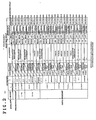
- the presence or absence of the pulldown detection operation of the pulldown detector 5 the content of the conversion operation of the I/P converter 6, the degree of the adjustment of each of the "sharp” and two-dimensional noise reduction (2DNR) processes of the picture quality adjustment circuit 8, the presence or absence of the conversion operation of the frame rate converter 9, and the frequency of the drive sequence of the PDP driving sequence generation circuit 10 are preset as to the respective setting data "on", “off” and "advanced" for the signal sorts of the signal supply sources 11 - 14.
- the controller 5 stores the corresponding relations of Fig. 2 as control information therein, and it generates the above instructions in control patterns which are determined in accordance with the control information of the corresponding relations and the setting data in the setting data memory 3.
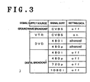
- the setting data are stored as shown in Fig. 3 by way of example.
- the setting data may be held at initial values at factory shipment, but they may well be made settable at will through the operation of the user.
- a reception quality worsens due to a weak electric field or ghost
- a ground wave broadcast of inferior picture quality is sometimes up-converted.
- the setting data for the ground wave broadcast and the digital broadcast are set at "off" in consideration of a case where the pulldown detector 5 does not operate stably.
- the setting data for the DVD in which the video signal indicating the movie is recorded in most cases, is set at "advanced".
- the setting data is set at "off” so that the frame rate conversion into 72Hz may not be performed in consideration of the jitter of a vertical synchronizing signal.
- the selection positions of the changeover switches SW1 and SW2 become the side of the video signal input terminal INV1 and the side of the external flag input terminal INF1 in accordance with the signal supply source data "ground wave broadcast" from the input signal selection circuit 1, respectively. It is assumed that the output video signal of the receiving tuner 11 for the ground wave broadcast as relayed by the changeover switch SW1 has been discriminated as the video signal of NTSC format by the signal sort discriminator 2.
- the signal sort data "CVBS" being the result of the discrimination is supplied to the setting data memory 3 and the controller 4.
- the controller 4 is supplied with the signal supply source data "ground wave broadcast” and the signal sort data "CVBS" in addition to the setting data "on”.
- the controller 4 instructs the pulldown detector 5 to execute the pulldown detection operation, it instructs the I/P converter 6 to perform the interpolation process corresponding to the result of the pulldown detection based on the pulldown detector 5, it instructs the changeover switch 7 to select the output of the I/P converter 6, it instructs the picture quality adjustment circuit 8 to execute the "sharp" process of medium level and the two-dimensional noise reduction process of low level, it instructs the frame rate converter 9 to perform no conversion, and it instructs the sequence generation circuit 10 to implement the drive sequence of 60Hz.
- the video signal selected and relayed by the changeover switch SW1 has been detected as the pulldown detection result to be the video signal of pulldown scheme, namely, the video signal of film source, it is converted into the progressive video signal by the inter-field interpolation process in the I/P converter 6.
- the relayed video signal has been detected not to be the video signal of film source, it is converted into the progressive video signal by the motion adaptive interpolation process in the I/P converter 6.
- the video signal is supplied to the picture quality adjustment circuit 8 through the changeover switch 7.
- the video signal is subjected to the "sharp" process of the picture quality at the medium level and the two-dimensional noise reduction process at the low level.
- the video signal subjected to the picture quality adjustment by the picture quality adjustment circuit 8 is supplied to the PDP driving sequence generation circuit 10 with its own vertical synchronizing frequency of 60Hz without undergoing the frame rate conversion in the frame rate converter 9.
- the PDP driving sequence generation circuit 10 drives the PDP or display panel 21 in the 60Hz sequence in accordance with the video signal having the vertical synchronizing frequency of 60Hz.
- the controller 4 instructs the pulldown detector 5 to execute no pulldown detection operation as shown in Fig. 2, it instructs the I/P converter 6 to perform the motion adaptive interpolation process, it instructs the changeover switch 7 to select the output of the I/P converter 6, it instructs the picture quality adjustment circuit 8 to execute the "sharp" process of high level and the two-dimensional noise reduction process of medium level, it instructs the frame rate converter 9 to perform no conversion, and it instructs the sequence generation circuit 10 to implement the 60Hz drive sequence.
- the video signal selected and relayed by the changeover switch SW1 is converted into the progressive video signal by the motion adaptive interpolation process in the I/P converter 6, and it is thereafter supplied to the picture quality adjustment circuit 8 through the changeover switch 7.
- the video signal is subjected to the "sharp" process of the picture quality at the high level and the two-dimensional noise reduction process at the medium level.
- the video signal subjected to the picture quality adjustment by the picture quality adjustment circuit 8 is supplied to the PDP driving sequence generation circuit 10 with its own vertical synchronizing frequency of 60Hz without undergoing the frame rate conversion in the frame rate converter 9.
- the PDP driving sequence generation circuit 10 drives the PDP or display panel 21 in the 60Hz sequence in accordance with the video signal having the vertical synchronizing frequency of 60Hz.
- the selection positions of the changeover switches SW1 and SW2 become the side of the video signal input terminal INV2 and the side of the external flag input terminal INF2 in accordance with the signal supply source data "VTR" from the input signal selection circuit 1, respectively. It is assumed that the output video signal of the video tape recorder 12 as relayed by the changeover switch SW1 has been discriminated as the video signal of NTSC format by the signal sort discriminator 2.
- the signal sort data "CVBS" of the result being the discrimination is supplied to the setting data memory 3 and the controller 4.
- the selection positions of the changeover switches SW1 and SW2 become the side of the video signal input terminal INV3 and the side of the external flag input terminal INF3 in accordance with the signal supply source data "DVD" from the input signal selection circuit 1, respectively.
- the output video signal of the DVD player 13 as relayed by the changeover switch SW1 has been discriminated as the video signal of 480i ("interlace" of 480 scanning lines) scheme by the signal sort discriminator 2.
- the signal sort data "480i" being the result of the discrimination is supplied to the setting data memory 3 and the controller 4.
- the controller 4 is supplied with the signal supply source data "DVD" and the signal sort data "480i” in addition to the setting data "off”. As shown in Fig. 2, the controller 4 instructs the pulldown detector 5 to execute no pulldown detection operation, it instructs the I/P converter 6 to perform the motion adaptive interpolation process, it instructs the changeover switch 7 to select the output of the I/P converter 6, it instructs the picture quality adjustment circuit 8 to execute the "sharp" process of high level and the two-dimensional noise reduction process of medium level, it instructs the frame rate converter 9 to perform no conversion, and it instructs the sequence generation circuit 10 to implement the drive sequence of 60Hz.
- the video signal from the DVD player 13 as selected and relayed by the changeover switch SW1 is converted into the progressive video signal by the motion adaptive interpolation process in the I/P converter 6, and it is thereafter supplied to the picture quality adjustment circuit 8 through the changeover switch 7.
- the video signal is subjected to the "sharp" process of the picture quality at the high level and the two-dimensional noise reduction process at the medium level.
- the video signal subjected to the picture quality adjustment by the picture quality adjustment circuit 8 is supplied to the PDP driving sequence generation circuit 10 with its own vertical synchronizing frequency of 60Hz without undergoing the frame rate conversion in the frame rate converter 9.
- the PDP driving sequence generation circuit 10 drives the PDP or display panel 21 in the 60Hz sequence in accordance with the video signal having the vertical synchronizing frequency of 60Hz.
- the controller 4 instructs the pulldown detector 5 to execute the pulldown detection operation as shown in Fig. 2, it instructs the I/P converter 6 to perform the interpolation process corresponding to the result of the pulldown detection based on the pulldown detector 5, it instructs the changeover switch 7 to select the output of the I/P converter 6, it instructs the picture quality adjustment circuit 8 to execute the "sharp" process of medium level and the two-dimensional noise reduction process of low level, it instructs the frame rate converter 9 to perform no conversion, and it instructs the sequence generation circuit 10 to implement the 60Hz drive sequence.
- the video signal from the DVD player 13 as selected and relayed by the changeover switch SW1 has been detected as the pulldown detection result to be the video signal of pulldown scheme, namely, the video signal of film source, it is converted into the progressive video signal by the inter-field interpolation process in the I/P converter 6.
- the relayed video signal has been detected not to be the video signal of film source, it is converted into the progressive video signal by the motion adaptive interpolation process in the I/P converter 6.
- the video signal is supplied to the picture quality adjustment circuit 8 through the changeover switch 7.
- the video signal is subjected to the "sharp" process of the picture quality at the medium level and the two-dimensional noise reduction process at the low level.
- the video signal subjected to the picture quality adjustment by the picture quality adjustment circuit 8 is supplied to the PDP driving sequence generation circuit 10 with its own vertical synchronizing frequency of 60Hz without undergoing the frame rate conversion in the frame rate converter 9.
- the PDP driving sequence generation circuit 10 drives the PDP or display panel 21 in the 60Hz sequence in accordance with the video signal having the vertical synchronizing frequency of 60Hz.
- the controller 4 instructs the pulldown detector 5 to execute the pulldown detection operation as shown in Fig. 2, it instructs the I/P converter 6 to perform the interpolation process corresponding to the result of the pulldown detection based on the pulldown detector 5, it instructs the changeover switch 7 to select the output of the I/P converter 6, it instructs the picture quality adjustment circuit 8 to execute the "sharp" process of medium level and the two-dimensional noise reduction process of low level, it instructs the frame rate converter 9 to perform the conversion, and it instructs the sequence generation circuit 10 to implement the 72Hz drive sequence.
- the video signal from the DVD player 13 as selected and relayed by the changeover switch SW1 has been detected as the pulldown detection result to be the video signal of pulldown scheme, namely, the video signal of film source, it is converted into the progressive video signal by the inter-field interpolation process in the I/P converter 6.
- the relayed video signal has been detected not to be the video signal of film source, it is converted into the progressive video signal by the motion adaptive interpolation process in the I/P converter 6.
- the video signal is supplied to the picture quality adjustment circuit 8 through the changeover switch 7.
- the video signal is subjected to the "sharp" process of the picture quality at the medium level and the two-dimensional noise reduction process at the low level.
- the video signal subjected to the picture quality adjustment by the picture quality adjustment circuit 8 has a vertical synchronizing frequency of 60Hz, but it is converted into a video signal having a vertical synchronizing frequency of 72Hz in the frame rate converter 9.
- the video signal after the conversion is supplied to the PDP driving sequence generation circuit 10.
- the PDP driving sequence generation circuit 10 drives the PDP or display panel 21 in the 72Hz sequence in accordance with the video signal having the vertical synchronizing frequency of 72Hz.
- the output video signal of the DVD player 13 as relayed by the changeover switch SW1 has been discriminated as the video signal of 480p ("progressive" of 480 scanning lines) scheme by the signal sort discriminator 2.
- the signal sort data "480p” being the result of the discrimination is supplied to the setting data memory 3 and the controller 4.
- the setting data of a storage location designated in accordance with the signal sort data "480p” and the signal supply source data "DVD" from the input signal selection circuit 1 is "off" in the setting data memory 3, then this setting data "off” is read out by the controller 4.
- the controller 4 instructs the pulldown detector 5 to execute no pulldown detection operation as shown in Fig. 2, it instructs the changeover switch 7 to select "through”, it instructs the picture quality adjustment circuit 8 to execute the "sharp” process of high level and the two-dimensional noise reduction process of medium level, it instructs the frame rate converter 9 to perform no conversion, and it instructs the sequence generation circuit 10 to implement the 60Hz drive sequence.
- the output video signal of the DVD player 13 as relayed by the changeover switch SW1 is supplied to the picture quality adjustment circuit 8 through the changeover switch 7 without passing through the I/P converter 6.
- the other operations are the same as in the case where the setting data "off" has been read out from the setting data memory 3 when the signal sort data is "480i" in the DVD playback mode.
- the controller 4 instructs the pulldown detector 5 to execute the pulldown detection operation as shown in Fig. 2, it instructs the changeover switch 7 to select "through”, it instructs the picture quality adjustment circuit 8 to execute the "sharp” process of medium level and the two-dimensional noise reduction process of low level, it instructs the frame rate converter 9 to perform the conversion, and it instructs the sequence generation circuit 10 to implement the 72Hz drive sequence.
- the output video signal of the DVD player 13 as relayed by the changeover switch SW1 is supplied to the picture quality adjustment circuit 8 through the changeover switch 7 without passing through the pulldown detector 5.
- the other operations are the same as in the case where the setting data "advanced" has been read out from the setting data memory 3 when the signal sort data is "480i" in the DVD playback mode.
- the selection positions of the changeover switches SW1 and SW2 become the side of the video signal input terminal INV4 and the side of the external flag input terminal INF4 in accordance with the signal supply source data "digital broadcast" from the input signal selection circuit 1, respectively.
- the output video signal of the receiving tuner 14 as relayed by the changeover switch SW1 is discriminated by the signal sort discriminator 2.
- the pulldown detector 5 supplies the I/P converter 6 with a signal which corresponds to whether or not a content or video signal indicated by the output flag is the video signal of film source, without performing the pulldown detection operation.
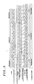
- Fig. 4 illustrates the interlace/progressive conversion and the frame rate conversion.
- the input video signal can be converted into a progressive video signal "Video prog" having 525 scanning lines.
- the outputted video signal is supplied to the PDP driving sequence generation circuit 10.
- the video signal of film source conforming to the NTSC format is a video signal of 2-3 pulldown scheme in which a field train consists of fields "Film A odd", “Film A even”, “Film B odd”, “Film B even”, “Film B odd”, ⁇ .
- "Film A odd” denotes the first field of a frame A
- "Film A even” the second field of the frame A.
- the input video signal can be converted into the progressive video signal having 525 scanning lines.
- the vertical synchronizing frequency of the video signal conforming to the PAL system is 50Hz. Therefore, the I/P converter 6 repeats forming a progressive video signal of one frame out of 2 fields of the video signal, and then outputting the progressive video signal twice in succession.
- the frame rate converter 9 converts the progressive video signal whose vertical synchronizing frequency is 50Hz, into a video signal which has a frame rate of 75Hz.
- the foregoing embodiments have mentioned the construction in which the video signal having the vertical synchronizing frequency of 50Hz (the video signal of film source conforming to the PAL system) is converted into the video signal having the frame rate of 75Hz, and the construction in which the video signal having the vertical synchronizing frequency of 60Hz (the video signal of film source conforming to the NTSC format) is converted into the video signal having the frame rate of 72Hz.
- the present invention is not restricted to the constructions, but it may well convert the video signal whose vertical synchronizing frequency is 50Hz, into a video signal which has a frame rate of (25 ⁇ N)Hz (where N denotes a positive integer) such as 25Hz or 100Hz, and the video signal whose vertical synchronizing frequency is 60Hz, into a video signal which has a frame rate of (24 ⁇ N)Hz (where N denotes a positive integer) such as 24Hz, 48Hz or 96Hz.
- a video signal whose vertical synchronizing frequency is (24 ⁇ M)Hz (where M denotes a positive integer) (for example, a video signal of 24Hz)
- M denotes a positive integer
- M ⁇ N a video signal of 48Hz or 72Hz
- a video signal whose vertical synchronizing frequency is (25 ⁇ M)Hz (where M denotes a positive integer) (for example, a video signal of 25Hz) is inputted
- M denotes a positive integer
- a video signal of 25Hz it may well be similarly converted into a video signal which has a frame rate of (25 ⁇ N)Hz (where N denotes a positive integer, and M ⁇ N holds) (for example, a video signal of 50Hz or 75Hz).
- the present invention is not restricted to the PDP.
- the present invention is also applicable to another flat panel display which employs organic electroluminescent elements or the like luminous elements.
- the operation of at least one of film source discrimination means, interlace/progressive conversion means and frame rate conversion means is controlled in accordance with an operation mode which corresponds to the sort and signal supply source of an input video signal. Accordingly, conversion operations can be performed in appropriate operation modes for video signals of both film source and video source, so that enhancements in display qualities can be attained.
Abstract
A video signal conversion apparatus which can enhance
display qualities for video signals of both film source and
video source. The conversion apparatus includes an input
signal discrimination unit which discriminates the sort and
signal supply source of an input video signal, and an
operation mode setting unit which sets the operation modes
of the individual sorts of video signals for each of a
plurality of signal supply sources. The operation mode
which corresponds to the sort and signal supply source of
the input video signal as discriminated by the input signal
discrimination unit is obtained from the operation mode
setting unit, and the operation of at least one of a film
source discrimination unit, an interlace/progressive
conversion unit and a frame rate conversion unit is
controlled in accordance with the obtained operation mode.
Description
- The present invention relates to a video signal conversion apparatus which converts an input video signal so as to be displayable on a display apparatus with a high picture quality.
- Video signals of film source based on movies or films are often contained in video signals of standard television systems such as the NTSC format. The movie or film consists of 24 frames per second. On the other hand, the video signal of the standard television system consists of 30 frames per second, and it is a video signal of interlaced scanning in which one frame is constituted by 2 fields. Since the numbers of frames per second are different, the frames of the movie or film are usually subjected to television-cinema conversion by a 2-3 pulldown scheme so as to obtain the video signal of the standard television system.
- With the 2-3 pulldown scheme, the first and second fields of the first frame of the video signal are created from the first frame of the movie or film, the first and second fields of the second frame and the first field of the third frame of the video signal from the second frame, and the second field of the third frame and the first field of the fourth frame of the video signal from the third frame. Regarding the subsequent frames, the video signal is created for 2 fields, for 3 fields, for 2 fields, for 3 fields, ····· from the successive frames of the film by similar conversion steps.
- In this way, the movie or film is converted into that video signal of the standard television system in which the 2 frames of the former correspond to the 5 frames of the latter, and in which the video signal of 2 fields and the video signal of 3 fields are alternately repeated in correspondence with the frames of the movie or film.
- Meanwhile, in a case where a picture based on the video signal of interlaced scanning subjected to the television-cinema conversion in this manner is displayed by a display apparatus such as PDP, the above-mentioned third frame, for example, in the successive frames of the video signal is formed of the combination between the pictures of the second frame and third frame of the movie or film. This has posed the problem that the video signal is inferior in picture quality to the original movie or film. It has been necessary for coping with the problem to discriminate whether an input video signal is a video signal of film source or a video signal of so-called "video source" unlike the video signal of film source, and to execute the process of picture quality adjustment for the video signal of film source.
- In this regard, however, there has been the problem that the discrimination concerning whether or not the input video signal is the video signal based on the film source does not stably operate in some cases, due to the differences of the signal supply sources of input video signals, so a good picture quality is sometimes unobtainable.
- Therefore, the present invention is intended to solve the above problem mentioned by way of example, and it has for its object to provide a video signal conversion apparatus which can enhance display qualities for video signals of both the film source and the video source.
- A video signal conversion apparatus according to
claim 1 of the present invention consists in a video signal conversion apparatus wherein an input video signal is converted into a progressive video signal of predetermined frame rate, characterized by comprising a film source discrimination means for discriminating whether or not the input video signal is a video signal of film source as based on a film; an interlace/progressive conversion means for converting which, when the input video signal is an interlaced video signal, the input video signal into the progressive video signal by a conversion method conforming to a result of the discrimination by said film source discrimination means and then outputs the progressive video signal, and for outputting, when the input video signal is not the interlaced video signal, the input video signal as it is; a frame rate conversion means for converting the output video signal of said interlace/progressive conversion means into a video signal of higher frame rate in accordance with the result of the discrimination by said film source discrimination means; an input signal discrimination means which discriminates a sort and a signal supply source of the input video signal; an operation mode setting means for setting operation modes of individual sorts of video signals of each of a plurality of signal supply sources; and a control means for obtaining from said operation mode setting means, the operation mode corresponding to the sort and the signal supply source of the input video signal as discriminated by said input signal discrimination means, and for controlling an operation of at least one of said film source discrimination means, said interlace/progressive conversion means and said frame rate conversion means in accordance with the obtained operation mode. -
- Fig. 1 is a block diagram showing the construction of a video signal conversion apparatus according to the present invention;
- Fig. 2 is a diagram showing the operations of individual units in the apparatus, as to respective setting data "on", "off" and "advanced" for the individual signal sorts of signal supply sources;
- Fig. 3 is a diagram showing examples of setting data stored in a setting data memory; and
- Fig. 4 is a diagram showing the operating states of the individual units of the apparatus in Fig. 1, at the respective synchronous timings thereof in the case where an input video signal is a video signal of NTSC format.
-
- Now, embodiments of the present invention will be described in detail with reference to the drawings.
- Fig. 1 shows a video signal conversion apparatus according to the present invention. The video signal conversion apparatus includes an input
signal selection circuit 1, asignal sort discriminator 2, asetting data memory 3, acontroller 4, a pulldown detector 5, an I/P (interlace/progressive)converter 6, achangeover switch 7, a picturequality adjustment circuit 8, aframe rate converter 9 and a PDP drivingsequence generation circuit 10. Also, the video signal conversion apparatus has video signal input terminals INV1 - INV4, external flag input terminals INF1 - INF4, and changeover switches SW1 and SW2. Signal supply sources are connected to the respective video signal input terminals INV1 - INV4, and video signals are supplied from the signal supply sources. In this embodiment, a receivingtuner 11 for a ground wave broadcast, a video tape recorder (VTR) 12, aDVD player 13 and a receivingtuner 14 for a digital broadcast are employed as the signal supply sources. The video signal output terminals of the signal supply sources 11 - 14 are connected to the video signal input terminals INV1 - INV4 in the order mentioned. In this embodiment, among the signal supply sources 11 - 14, thereceiving tuner 14 for the digital broadcast is provided with a flag output terminal, which is connected to the external flag input terminal INF4. The external flag input terminals, for example, INF1 - INF3 which correspond to the signal supply sources having no flag output terminals are held open. Thereceiving tuner 14 delivers from the flag output terminal, an Mpeg flag which indicates whether or not the video signal being outputted is a video signal of film source based on a film. - The output video signals of the respective signal supply sources 11 - 14 are all digital signals. The receiving
tuner 11 for the ground wave broadcast and thevideo tape recorder 12 output video signals of NTSC format, respectively. TheDVD player 13 outputs an interlaced video signal or a progressive video signal which has 480 scanning lines. The receivingtuner 14 for the digital broadcast outputs any of an interlaced video signal having 480 scanning lines, a progressive video signal having 480 scanning lines, a progressive video signal having 720 scanning lines, and an interlaced video signal having 1080 scanning lines. - Each of the changeover switches SW1 and SW2 is a switch which has four stationary contacts, and in which any of the stationary contacts is selectively connected by a movable contact in accordance with a selection command signal from the input
signal selection circuit 1. The video signal input terminals INV1 - INV4 are respectively connected to the stationary contacts of the changeover switch SW1. The external flag input terminals INF1 - INF4 are respectively connected to the stationary contacts of the changeover switch SW2. The changeover switch SW1 relays and supplies the video signal supplied to the selected and connected stationary contact, to thesignal sort discriminator 2, pulldown detector 5 and I/P converter 6. The changeover switch SW2 relays and supplies the flag supplied to the selected and connected stationary terminal, to the pulldown detector 5. - The input
signal selection circuit 1 includes an operating portion not shown, and it outputs to the changeover switches SW1 and SW2, the selection command signals for changing-over the selected positions of these changeover switches SW1 and SW2 in accordance with the user's operations of the operating portion. Besides, the inputsignal selection circuit 1 supplies thesetting data memory 3 and thecontroller 4 with signal supply source data which indicates the input terminal currently under selection (any of "ground wave broadcast", "VTR", "DVD" and "digital broadcast"). Incidentally, since the corresponding relations between the input terminals INV1 - INV4 and the signal supply sources 11 - 14 are fixed, the signal supply source data which indicates the input terminal currently under selection is obtained in correspondence with the selected position of the changeover switch SW1. - The signal sort
discriminator 2 discriminates the sort of the video signal selected and relayed by the changeover switch SW1. The sorts of video signals are divided into standard video signals (CVBS) such as the video signal of NTSC format, and the other video signals. Further, the other video signals are divided depending upon the number of scanning lines, and interlace/non-interlace. Signal sort data which indicates a result discriminated by thesignal sort discriminator 2, is supplied to thesetting data memory 3 and thecontroller 4. The inputsignal selection circuit 1 and thesignal sort discriminator 2 constitute input signal discrimination means. - The setting
data memory 3 is operation mode setting means. Setting data which indicate operation modes in the individual sorts of the video signals of the respective signal supply sources, are written in thesetting data memory 3 beforehand. The setting data determine the respective control states of the pulldown detector 5, I/P converter 6,changeover switch 7, picturequality adjustment circuit 8,frame rate converter 9 and PDP drivingsequence generation circuit 10 based on the controller 5. In thesetting data memory 3, the setting data is read out from a storage location specified in accordance with the signal supply source data from the inputsignal selection circuit 1 and the signal sort data from thesignal sort discriminator 2, by thecontroller 4. The setting data is any of "on", "off" and "advanced". Incidentally, thecontroller 4 may well designate the storage location of thesetting data memory 3 in accordance with the signal supply source data from the inputsignal selection circuit 1 and the signal sort data from thesignal sort discriminator 2, so as to read out the setting data from the designated storage location. - The
controller 4 is control means, and it generates various instructions for controlling the respective operations of the pulldown detector 5, I/P converter 6,changeover switch 7, picturequality adjustment circuit 8,frame rate converter 9 and PDP drivingsequence generation circuit 10, on the basis of the setting data supplied from thesetting data memory 3. - The pulldown detector 5 is film source discrimination means. When a detection command has been generated from the
controller 4, the pulldown detector 5 detects whether or not the video signal selected and relayed by the changeover switch SW1 is a video signal of film source converted by a 2-2 or 2-3 pulldown scheme. The result of the detection is supplied as a signal to the I/P converter 6. Besides, when the pulldown detector 5 is supplied with the flag through the changeover switch SW2, it supplies the I/P converter 6 with the content of the flag, that is, a signal which corresponds to whether or not the selected and relayed video signal is the video signal of film source. - The I/
P converter 6 constructs interlace/progressive conversion means, together with thechangeover switch 7. In a case where an I/P conversion command has been generated from thecontroller 4, and where the signal from the pulldown detector 5 indicates the video signal of film source, the I/P converter 6 converts the video signal selected and relayed by the changeover switch SW1, into a progressive video signal on the basis of an inter-field interpolation process. Besides, in a case where the I/P conversion command has been generated from thecontroller 4, but where the signal from the pulldown detector 5 does not indicate the detection of the video signal of film source, the I/P converter 6 converts the video signal selected and relayed by the changeover switch SW1, into a progressive video signal on the basis of a motion adaptive interpolation process. - The
changeover switch 7 outputs either of the video signal selected and relayed by the changeover switch SW1 and the video signal outputted from the I/P converter 6, to the picturequality adjustment circuit 8 in accordance with a selection command from thecontroller 4. - The picture
quality adjustment circuit 8 executes the "sharp" process and two-dimensional noise reduction process of a picture quality for the video signal relayed from thechangeover switch 7, in accordance with a picture quality adjustment command from thecontroller 4. Each of the processes is performed at any of low, medium and high levels. - The
frame rate converter 9 converts the video signal outputted from the picturequality adjustment circuit 8, from 60Hz to 72Hz in accordance with a frame rate conversion command from thecontroller 4. Besides, when supplied with a non-conversion command from thecontroller 4, theframe rate converter 9 outputs the video signal delivered from the picturequality adjustment circuit 8, as it is. - The PDP driving
sequence generation circuit 10 drives aPDP display panel 21 in accordance with the output video signal of theframe rate converter 9. - In the video signal conversion apparatus of such a construction, as shown in Fig. 2, the presence or absence of the pulldown detection operation of the pulldown detector 5, the content of the conversion operation of the I/
P converter 6, the degree of the adjustment of each of the "sharp" and two-dimensional noise reduction (2DNR) processes of the picturequality adjustment circuit 8, the presence or absence of the conversion operation of theframe rate converter 9, and the frequency of the drive sequence of the PDP drivingsequence generation circuit 10 are preset as to the respective setting data "on", "off" and "advanced" for the signal sorts of the signal supply sources 11 - 14. The controller 5 stores the corresponding relations of Fig. 2 as control information therein, and it generates the above instructions in control patterns which are determined in accordance with the control information of the corresponding relations and the setting data in the settingdata memory 3. - Besides, as shown in Fig. 2, when the external flag has been supplied to the pulldown detector 5, the pulldown detection operation of this pulldown detector 5 is not performed, and whether or not the relayed video signal is the video signal converted by the pulldown scheme is determined in accordance with the content of the external flag.
- In the setting
data memory 3, the setting data are stored as shown in Fig. 3 by way of example. The setting data may be held at initial values at factory shipment, but they may well be made settable at will through the operation of the user. In the ground wave broadcast, a reception quality worsens due to a weak electric field or ghost, and in the digital broadcast, a ground wave broadcast of inferior picture quality is sometimes up-converted. In the setting data example of Fig. 3, therefore, the setting data for the ground wave broadcast and the digital broadcast are set at "off" in consideration of a case where the pulldown detector 5 does not operate stably. Besides, the setting data for the DVD, in which the video signal indicating the movie is recorded in most cases, is set at "advanced". Regarding the VTR, the setting data is set at "off" so that the frame rate conversion into 72Hz may not be performed in consideration of the jitter of a vertical synchronizing signal. - In a case where a ground-wave-broadcast reception mode has been selected by the user's operation, the selection positions of the changeover switches SW1 and SW2 become the side of the video signal input terminal INV1 and the side of the external flag input terminal INF1 in accordance with the signal supply source data "ground wave broadcast" from the input
signal selection circuit 1, respectively. It is assumed that the output video signal of the receivingtuner 11 for the ground wave broadcast as relayed by the changeover switch SW1 has been discriminated as the video signal of NTSC format by thesignal sort discriminator 2. The signal sort data "CVBS" being the result of the discrimination is supplied to the settingdata memory 3 and thecontroller 4. Here, if the setting data of a storage location designated in accordance with the signal sort data "CVBS" and the signal supply source data "ground wave broadcast" from the inputsignal selection circuit 1 is "on" in the settingdata memory 3, then this setting data "on" is read out by thecontroller 4. - Accordingly, the
controller 4 is supplied with the signal supply source data "ground wave broadcast" and the signal sort data "CVBS" in addition to the setting data "on". As shown in Fig. 2, thecontroller 4 instructs the pulldown detector 5 to execute the pulldown detection operation, it instructs the I/P converter 6 to perform the interpolation process corresponding to the result of the pulldown detection based on the pulldown detector 5, it instructs thechangeover switch 7 to select the output of the I/P converter 6, it instructs the picturequality adjustment circuit 8 to execute the "sharp" process of medium level and the two-dimensional noise reduction process of low level, it instructs theframe rate converter 9 to perform no conversion, and it instructs thesequence generation circuit 10 to implement the drive sequence of 60Hz. - Owing to the instructions, in a case where the video signal selected and relayed by the changeover switch SW1 has been detected as the pulldown detection result to be the video signal of pulldown scheme, namely, the video signal of film source, it is converted into the progressive video signal by the inter-field interpolation process in the I/
P converter 6. In a case where the relayed video signal has been detected not to be the video signal of film source, it is converted into the progressive video signal by the motion adaptive interpolation process in the I/P converter 6. After having been converted into the progressive video signal, the video signal is supplied to the picturequality adjustment circuit 8 through thechangeover switch 7. In the picturequality adjustment circuit 8, the video signal is subjected to the "sharp" process of the picture quality at the medium level and the two-dimensional noise reduction process at the low level. The video signal subjected to the picture quality adjustment by the picturequality adjustment circuit 8 is supplied to the PDP drivingsequence generation circuit 10 with its own vertical synchronizing frequency of 60Hz without undergoing the frame rate conversion in theframe rate converter 9. The PDP drivingsequence generation circuit 10 drives the PDP ordisplay panel 21 in the 60Hz sequence in accordance with the video signal having the vertical synchronizing frequency of 60Hz. - If, in the ground-wave-broadcast reception mode, the setting data "off" has been read out from the setting
data memory 3 by thecontroller 4, then thecontroller 4 instructs the pulldown detector 5 to execute no pulldown detection operation as shown in Fig. 2, it instructs the I/P converter 6 to perform the motion adaptive interpolation process, it instructs thechangeover switch 7 to select the output of the I/P converter 6, it instructs the picturequality adjustment circuit 8 to execute the "sharp" process of high level and the two-dimensional noise reduction process of medium level, it instructs theframe rate converter 9 to perform no conversion, and it instructs thesequence generation circuit 10 to implement the 60Hz drive sequence. - Owing to the instructions, the video signal selected and relayed by the changeover switch SW1 is converted into the progressive video signal by the motion adaptive interpolation process in the I/
P converter 6, and it is thereafter supplied to the picturequality adjustment circuit 8 through thechangeover switch 7. In the picturequality adjustment circuit 8, the video signal is subjected to the "sharp" process of the picture quality at the high level and the two-dimensional noise reduction process at the medium level. The video signal subjected to the picture quality adjustment by the picturequality adjustment circuit 8 is supplied to the PDP drivingsequence generation circuit 10 with its own vertical synchronizing frequency of 60Hz without undergoing the frame rate conversion in theframe rate converter 9. The PDP drivingsequence generation circuit 10 drives the PDP ordisplay panel 21 in the 60Hz sequence in accordance with the video signal having the vertical synchronizing frequency of 60Hz. - Next, in a case where a VTR playback mode based on the
video tape recorder 12 has been selected by the user's operation, the selection positions of the changeover switches SW1 and SW2 become the side of the video signal input terminal INV2 and the side of the external flag input terminal INF2 in accordance with the signal supply source data "VTR" from the inputsignal selection circuit 1, respectively. It is assumed that the output video signal of thevideo tape recorder 12 as relayed by the changeover switch SW1 has been discriminated as the video signal of NTSC format by thesignal sort discriminator 2. The signal sort data "CVBS" of the result being the discrimination is supplied to the settingdata memory 3 and thecontroller 4. Here, if the setting data of a storage location designated in accordance with the signal sort data "CVBS" and the signal supply source data "VTR" from the inputsignal selection circuit 1 is "on" in the settingdata memory 3, then this setting data "on" is read out by thecontroller 4. In contrast, if the setting data of the designated storage location is "off", then this setting data "off" is read out by thecontroller 4. - Accordingly, respective instructions which are issued from the
controller 4 in the case of the selection of the VTR playback mode are the same as those in the case of the selection of the ground-wave-broadcast reception mode, and hence, the respective operations of the pulldown detector 5, I/P converter 6,changeover switch 7, picturequality adjustment circuit 8,frame rate converter 9 and PDP drivingsequence generation circuit 10 are also the same. - Subsequently, in a case where a DVD playback mode based on the
DVD player 13 has been selected by the user's operation, the selection positions of the changeover switches SW1 and SW2 become the side of the video signal input terminal INV3 and the side of the external flag input terminal INF3 in accordance with the signal supply source data "DVD" from the inputsignal selection circuit 1, respectively. It is assumed that the output video signal of theDVD player 13 as relayed by the changeover switch SW1 has been discriminated as the video signal of 480i ("interlace" of 480 scanning lines) scheme by thesignal sort discriminator 2. The signal sort data "480i" being the result of the discrimination is supplied to the settingdata memory 3 and thecontroller 4. Here, if the setting data of a storage location designated in accordance with the signal sort data "480i" and the signal supply source data "DVD" from the inputsignal selection circuit 1 is "off" in the settingdata memory 3, then this setting data "off" is read out by thecontroller 4. - The
controller 4 is supplied with the signal supply source data "DVD" and the signal sort data "480i" in addition to the setting data "off". As shown in Fig. 2, thecontroller 4 instructs the pulldown detector 5 to execute no pulldown detection operation, it instructs the I/P converter 6 to perform the motion adaptive interpolation process, it instructs thechangeover switch 7 to select the output of the I/P converter 6, it instructs the picturequality adjustment circuit 8 to execute the "sharp" process of high level and the two-dimensional noise reduction process of medium level, it instructs theframe rate converter 9 to perform no conversion, and it instructs thesequence generation circuit 10 to implement the drive sequence of 60Hz. - Owing to the instructions, the video signal from the
DVD player 13 as selected and relayed by the changeover switch SW1 is converted into the progressive video signal by the motion adaptive interpolation process in the I/P converter 6, and it is thereafter supplied to the picturequality adjustment circuit 8 through thechangeover switch 7. In the picturequality adjustment circuit 8, the video signal is subjected to the "sharp" process of the picture quality at the high level and the two-dimensional noise reduction process at the medium level. The video signal subjected to the picture quality adjustment by the picturequality adjustment circuit 8 is supplied to the PDP drivingsequence generation circuit 10 with its own vertical synchronizing frequency of 60Hz without undergoing the frame rate conversion in theframe rate converter 9. The PDP drivingsequence generation circuit 10 drives the PDP ordisplay panel 21 in the 60Hz sequence in accordance with the video signal having the vertical synchronizing frequency of 60Hz. - If, for the signal sort data "480i" in the DVD playback mode, the setting data "on" has been read out from the setting
data memory 3 by thecontroller 4, then thecontroller 4 instructs the pulldown detector 5 to execute the pulldown detection operation as shown in Fig. 2, it instructs the I/P converter 6 to perform the interpolation process corresponding to the result of the pulldown detection based on the pulldown detector 5, it instructs thechangeover switch 7 to select the output of the I/P converter 6, it instructs the picturequality adjustment circuit 8 to execute the "sharp" process of medium level and the two-dimensional noise reduction process of low level, it instructs theframe rate converter 9 to perform no conversion, and it instructs thesequence generation circuit 10 to implement the 60Hz drive sequence. - Owing to the instructions, in a case where the video signal from the
DVD player 13 as selected and relayed by the changeover switch SW1 has been detected as the pulldown detection result to be the video signal of pulldown scheme, namely, the video signal of film source, it is converted into the progressive video signal by the inter-field interpolation process in the I/P converter 6. In a case where the relayed video signal has been detected not to be the video signal of film source, it is converted into the progressive video signal by the motion adaptive interpolation process in the I/P converter 6. After having been converted into the progressive video signal, the video signal is supplied to the picturequality adjustment circuit 8 through thechangeover switch 7. In the picturequality adjustment circuit 8, the video signal is subjected to the "sharp" process of the picture quality at the medium level and the two-dimensional noise reduction process at the low level. The video signal subjected to the picture quality adjustment by the picturequality adjustment circuit 8 is supplied to the PDP drivingsequence generation circuit 10 with its own vertical synchronizing frequency of 60Hz without undergoing the frame rate conversion in theframe rate converter 9. The PDP drivingsequence generation circuit 10 drives the PDP ordisplay panel 21 in the 60Hz sequence in accordance with the video signal having the vertical synchronizing frequency of 60Hz. - If, in the DVD playback mode, the setting data "advanced" has been read out from the setting
data memory 3 by thecontroller 4, then thecontroller 4 instructs the pulldown detector 5 to execute the pulldown detection operation as shown in Fig. 2, it instructs the I/P converter 6 to perform the interpolation process corresponding to the result of the pulldown detection based on the pulldown detector 5, it instructs thechangeover switch 7 to select the output of the I/P converter 6, it instructs the picturequality adjustment circuit 8 to execute the "sharp" process of medium level and the two-dimensional noise reduction process of low level, it instructs theframe rate converter 9 to perform the conversion, and it instructs thesequence generation circuit 10 to implement the 72Hz drive sequence. - Owing to the instructions, in a case where the video signal from the
DVD player 13 as selected and relayed by the changeover switch SW1 has been detected as the pulldown detection result to be the video signal of pulldown scheme, namely, the video signal of film source, it is converted into the progressive video signal by the inter-field interpolation process in the I/P converter 6. In a case where the relayed video signal has been detected not to be the video signal of film source, it is converted into the progressive video signal by the motion adaptive interpolation process in the I/P converter 6. After having been converted into the progressive video signal, the video signal is supplied to the picturequality adjustment circuit 8 through thechangeover switch 7. In the picturequality adjustment circuit 8, the video signal is subjected to the "sharp" process of the picture quality at the medium level and the two-dimensional noise reduction process at the low level. The video signal subjected to the picture quality adjustment by the picturequality adjustment circuit 8 has a vertical synchronizing frequency of 60Hz, but it is converted into a video signal having a vertical synchronizing frequency of 72Hz in theframe rate converter 9. The video signal after the conversion is supplied to the PDP drivingsequence generation circuit 10. The PDP drivingsequence generation circuit 10 drives the PDP ordisplay panel 21 in the 72Hz sequence in accordance with the video signal having the vertical synchronizing frequency of 72Hz. - It is assumed that the output video signal of the
DVD player 13 as relayed by the changeover switch SW1 has been discriminated as the video signal of 480p ("progressive" of 480 scanning lines) scheme by thesignal sort discriminator 2. The signal sort data "480p" being the result of the discrimination is supplied to the settingdata memory 3 and thecontroller 4. Here, if the setting data of a storage location designated in accordance with the signal sort data "480p" and the signal supply source data "DVD" from the inputsignal selection circuit 1 is "off" in the settingdata memory 3, then this setting data "off" is read out by thecontroller 4. - If, for the signal sort data "480p" in the DVD playback mode, the setting data "off" has been read out from the setting
data memory 3 by thecontroller 4, then thecontroller 4 instructs the pulldown detector 5 to execute no pulldown detection operation as shown in Fig. 2, it instructs thechangeover switch 7 to select "through", it instructs the picturequality adjustment circuit 8 to execute the "sharp" process of high level and the two-dimensional noise reduction process of medium level, it instructs theframe rate converter 9 to perform no conversion, and it instructs thesequence generation circuit 10 to implement the 60Hz drive sequence. - Owing to the instructions, the output video signal of the
DVD player 13 as relayed by the changeover switch SW1 is supplied to the picturequality adjustment circuit 8 through thechangeover switch 7 without passing through the I/P converter 6. The other operations are the same as in the case where the setting data "off" has been read out from the settingdata memory 3 when the signal sort data is "480i" in the DVD playback mode. - If, for the signal sort data "480p" in the DVD playback mode, the setting data "advanced" has been read out from the setting
data memory 3 by thecontroller 4, then thecontroller 4 instructs the pulldown detector 5 to execute the pulldown detection operation as shown in Fig. 2, it instructs thechangeover switch 7 to select "through", it instructs the picturequality adjustment circuit 8 to execute the "sharp" process of medium level and the two-dimensional noise reduction process of low level, it instructs theframe rate converter 9 to perform the conversion, and it instructs thesequence generation circuit 10 to implement the 72Hz drive sequence. - Owing to the instructions, the output video signal of the
DVD player 13 as relayed by the changeover switch SW1 is supplied to the picturequality adjustment circuit 8 through thechangeover switch 7 without passing through the pulldown detector 5. The other operations are the same as in the case where the setting data "advanced" has been read out from the settingdata memory 3 when the signal sort data is "480i" in the DVD playback mode. - Further, in a case where a digital-broadcast reception mode based on the receiving
tuner 14 for the digital broadcast has been selected by the user's operation, the selection positions of the changeover switches SW1 and SW2 become the side of the video signal input terminal INV4 and the side of the external flag input terminal INF4 in accordance with the signal supply source data "digital broadcast" from the inputsignal selection circuit 1, respectively. The output video signal of the receivingtuner 14 as relayed by the changeover switch SW1 is discriminated by thesignal sort discriminator 2. Besides, if the output flag of the receivingtuner 14 is relayed and supplied to the pulldown detector 5 by the changeover switch SW2, then the pulldown detector 5 supplies the I/P converter 6 with a signal which corresponds to whether or not a content or video signal indicated by the output flag is the video signal of film source, without performing the pulldown detection operation. - When the signal sort data is "480i", "480p", "720p ("progressive" of 720 scanning lines)" or "1080i ("interlace" of 1080 scanning lines)" in the digital-broadcast reception mode, individual operations are executed as indicated by the corresponding relations in Fig. 2. The respective operations are similar to the above operations for the signal sort data "480i" or "480p" in the DVD playback mode, and the description of the operations is repetitious, so that the operations shall not be further described here.
- Fig. 4 illustrates the interlace/progressive conversion and the frame rate conversion. As shown in Fig. 4, the video signal of NTSC format is a signal in which a first field "Video odd" and a second field "Video even" are repeated at a vertical synchronizing frequency of fv = 60Hz. Each time the I/
P converter 6 writes the video signal corresponding to 2 fields (first field "Video odd" and second field "Video even"), namely, one frame, into a first frame memory not shown, it reads the video signal corresponding to one frame, twice at the vertical synchronizing frequency of fv = 60Hz. Thus, the input video signal can be converted into a progressive video signal "Video prog" having 525 scanning lines. Theframe rate converter 9 writes the supplied progressive video signal into a second frame memory not shown, and it reads the progressive video signal "Video prog" corresponding to one frame as written into the second frame memory, at the vertical synchronizing frequency of fv = 60Hz. That is, theframe rate converter 9 outputs the same video signal "Video prog" as the written video signal "Video prog". The outputted video signal is supplied to the PDP drivingsequence generation circuit 10. This PDP drivingsequence generation circuit 10 drives the PDP ordisplay panel 21 in the 60Hz sequence in accordance with the video signal having the vertical synchronizing frequency of fv = 60Hz. - As shown in Fig. 4, the video signal of film source conforming to the NTSC format is a video signal of 2-3 pulldown scheme in which a field train consists of fields "Film A odd", "Film A even", "Film B odd", "Film B even", "Film B odd", ·····. "Film A odd" denotes the first field of a frame A, and "Film A even" the second field of the frame A. The vertical synchronizing frequency of the video signal of the NTSC format is fv = 60Hz. Therefore, each time the I/
P converter 6 writes the video signal corresponding to 2 fields (first field "Film A odd" and second field "Film A even"), into the first frame memory, it reads the video signal "Film A prog" corresponding to one frame, twice at the vertical synchronizing frequency of fv = 60Hz. Further, each time the I/P converter 6 writes the video signal corresponding to 2 fields (first field "Film B odd" and second field "Film B even"), into the first frame memory, it reads the video signal "Film B prog" corresponding to one frame, three times at the vertical synchronizing frequency of fv = 60Hz. The last field "Film B odd" of the 5 successive fields of the input video signal is neglected. Owing to the repetition of such operations, the input video signal can be converted into the progressive video signal having 525 scanning lines. Theframe rate converter 9 writes the supplied progressive video signal into the second frame memory, it reads the progressive video signal "Video prog" corresponding to one frame as written into the second frame memory, at a vertical synchronizing frequency of fv = 72Hz, and it supplies the read-out video signal to the PDP drivingsequence generation circuit 10. Besides, in the readout of the video signal corresponding to one frame, the same frame is read out twice every 5th frame. As shown in Fig. 4, the frame "Film A prog", a frame "Film C prog", ····· are read out twice, whereby the same frame succeeds over 3 frames in the video signal having the vertical synchronizing frequency of fv = 72Hz as obtained through the frame rate conversion. The PDP drivingsequence generation circuit 10 drives the PDP ordisplay panel 21 in the 72Hz sequence in accordance with the video signal having the vertical synchronizing frequency of fv = 72Hz. - Incidentally, although a case where a video signal of PAL system is inputted has not been mentioned in the above embodiment, the vertical synchronizing frequency of the video signal conforming to the PAL system is 50Hz. Therefore, the I/
P converter 6 repeats forming a progressive video signal of one frame out of 2 fields of the video signal, and then outputting the progressive video signal twice in succession. Theframe rate converter 9 converts the progressive video signal whose vertical synchronizing frequency is 50Hz, into a video signal which has a frame rate of 75Hz. - The foregoing embodiments have mentioned the construction in which the video signal having the vertical synchronizing frequency of 50Hz (the video signal of film source conforming to the PAL system) is converted into the video signal having the frame rate of 75Hz, and the construction in which the video signal having the vertical synchronizing frequency of 60Hz (the video signal of film source conforming to the NTSC format) is converted into the video signal having the frame rate of 72Hz. However, the present invention is not restricted to the constructions, but it may well convert the video signal whose vertical synchronizing frequency is 50Hz, into a video signal which has a frame rate of (25 × N)Hz (where N denotes a positive integer) such as 25Hz or 100Hz, and the video signal whose vertical synchronizing frequency is 60Hz, into a video signal which has a frame rate of (24 × N)Hz (where N denotes a positive integer) such as 24Hz, 48Hz or 96Hz.
- Besides, in a case where a video signal whose vertical synchronizing frequency is (24 × M)Hz (where M denotes a positive integer) (for example, a video signal of 24Hz) is inputted, it may well be similarly converted into a video signal which has a frame rate of (24 × N)Hz (where N denotes a positive integer, and M ≤ N holds) (for example, a video signal of 48Hz or 72Hz). Also, in a case where a video signal whose vertical synchronizing frequency is (25 × M)Hz (where M denotes a positive integer) (for example, a video signal of 25Hz) is inputted, it may well be similarly converted into a video signal which has a frame rate of (25 × N)Hz (where N denotes a positive integer, and M ≤ N holds) (for example, a video signal of 50Hz or 75Hz).
- Further, although the case of employing the PDP as the display panel has been mentioned in the foregoing embodiments, the present invention is not restricted to the PDP. The present invention is also applicable to another flat panel display which employs organic electroluminescent elements or the like luminous elements.
- As described above, according to the present invention, the operation of at least one of film source discrimination means, interlace/progressive conversion means and frame rate conversion means is controlled in accordance with an operation mode which corresponds to the sort and signal supply source of an input video signal. Accordingly, conversion operations can be performed in appropriate operation modes for video signals of both film source and video source, so that enhancements in display qualities can be attained.
Claims (8)
- A video signal conversion apparatus wherein an input video signal is converted into a progressive video signal of predetermined frame rate, comprising:a film source discrimination means for discriminating whether or not the input video signal is a video signal of film source as based on a film;an interlace/progressive conversion means for converting, when the input video signal is an interlaced video signal, the input video signal into the progressive video signal by a conversion method conforming to a result of the discrimination by said film source discrimination means and then outputs the progressive video signal, and for outputting, when the input video signal is not the interlaced video signal, the input video signal as it is;a frame rate conversion means for converting the output video signal of said interlace/progressive conversion means into a video signal of higher frame rate in accordance with the result of the discrimination by said film source discrimination means;an input signal discrimination means for discriminating a sort and a signal supply source of the input video signal;an operation mode setting means for setting operation modes of individual sorts of video signals of each of a plurality of signal supply sources; anda control means for obtaining from said operation mode setting means, the operation mode corresponding to the sort and the signal supply source of the input video signal as discriminated by said input signal discrimination means, and controlling an operation of at least one of said film source discrimination means, said interlace/progressive conversion means and said frame rate conversion means in accordance with the obtained operation mode.
- A video signal conversion apparatus as defined in claim 1, wherein:said input signal discrimination means includes a synchronizing-signal detection means for detecting a vertical synchronizing signal of the input video signal; andsaid interlace/progressive conversion means for outputting the progressive video signal in synchronism with the vertical synchronizing signal of the input video signal.
- A video signal conversion apparatus as defined in claim 2, wherein when the vertical synchronizing frequency of the input video signal is 50Hz, said interlace/progressive conversion means repeats forming the progressive video signal corresponding to one frame, out of 2 fields of the input video signal, so as to output the progressive video signal twice in succession; and when the vertical synchronizing frequency of the input video signal is 60Hz, said interlace/progressive conversion means repeats forming the progressive video signal corresponding to one frame, out of initial 2 fields of 5 fields of the input video signal, so as to output the progressive video signal twice in succession, forming the progressive video signal corresponding to one frame, out of 2 subsequent fields, so as to output the progressive video signal twice in succession, and neglecting one remaining field.
- A video signal conversion apparatus as defined in claims 1, 2 or 3 wherein when the result of the discrimination by said film source discrimination means indicates the film source, said frame rate conversion means converts the progressive video signal as to which a vertical synchronizing frequency of the input video signal is 50Hz, into a video signal which has a frame rate of (25 × N)Hz (where N denotes a positive integer); and when the result of the discrimination by said film source discrimination means indicates the film source, said frame rate conversion means converts the progressive video signal as to which a vertical synchronizing frequency of the input video signal is 60Hz, into a video signal which has a frame rate of (24 × N)Hz (where N denotes a positive integer).
- A video signal conversion apparatus as defined in claims 1, 2 or 3, wherein when a vertical synchronizing frequency of the input video signal is (25 × M)Hz (where M denotes a positive integer) based on the film source, said frame rate conversion means converts the input video signal into a video signal which has a frame rate (25 × N)Hz (where N denotes a positive integer, and M ≤ N holds).
- A video signal conversion apparatus as defined in claims 1, 2 or 3 wherein when a vertical synchronizing frequency of the input video signal is (24 × M)Hz (where M denotes a positive integer) based on the film source, said frame rate conversion means converts the input video signal into a video signal which has a frame rate (24 × N)Hz (where N denotes a positive integer, and M ≤ N holds).
- A video signal conversion apparatus as defined in claims 1, 2 or 3, wherein when the result of the discrimination by said film source discrimination means indicates the film source, said frame rate conversion means converts the progressive video signal as to which a vertical synchronizing frequency of the input video signal is 50Hz, into a video signal which has a frame rate of (25 × N)Hz (where N denotes a positive integer).
- A video signal conversion apparatus as defined in claims 1, 2 or 3, wherein when the result of the discrimination by said film source discrimination means indicates the film source, said frame rate conversion means converts the progressive video signal as to which a vertical synchronizing frequency of the input video signal is 60Hz, into a video signal which has a frame rate of (24 × N)Hz (where N denotes a positive integer).
Applications Claiming Priority (2)
| Application Number | Priority Date | Filing Date | Title |
|---|---|---|---|
| JP2003204412A JP4382408B2 (en) | 2003-07-31 | 2003-07-31 | Video signal converter |
| JP2003204412 | 2003-07-31 |
Publications (1)
| Publication Number | Publication Date |
|---|---|
| EP1503582A1 true EP1503582A1 (en) | 2005-02-02 |
Family
ID=33535617
Family Applications (1)
| Application Number | Title | Priority Date | Filing Date |
|---|---|---|---|
| EP04017354A Withdrawn EP1503582A1 (en) | 2003-07-31 | 2004-07-22 | Video signal conversion apparatus |
Country Status (3)
| Country | Link |
|---|---|
| US (1) | US7268820B2 (en) |
| EP (1) | EP1503582A1 (en) |
| JP (1) | JP4382408B2 (en) |
Cited By (4)
| Publication number | Priority date | Publication date | Assignee | Title |
|---|---|---|---|---|
| EP1860876A2 (en) | 2006-05-22 | 2007-11-28 | Sony Corporation | Video signal processing apparatus and image display apparatus |
| EP2175645A1 (en) * | 2008-10-08 | 2010-04-14 | Sony Corporation | Picture signal processing system, playback apparatus and display apparatus, and picture signal processing method |
| US8411931B2 (en) | 2006-06-23 | 2013-04-02 | Imax Corporation | Methods and systems for converting 2D motion pictures for stereoscopic 3D exhibition |
| US8842730B2 (en) | 2006-01-27 | 2014-09-23 | Imax Corporation | Methods and systems for digitally re-mastering of 2D and 3D motion pictures for exhibition with enhanced visual quality |
Families Citing this family (18)
| Publication number | Priority date | Publication date | Assignee | Title |
|---|---|---|---|---|
| JP2005027068A (en) * | 2003-07-03 | 2005-01-27 | Pioneer Electronic Corp | Video signal converting apparatus and method therefor |
| KR20060021446A (en) * | 2004-09-03 | 2006-03-08 | 삼성전자주식회사 | Method for deinterlacing and apparatus thereof |
| JP4703267B2 (en) * | 2005-05-31 | 2011-06-15 | 株式会社東芝 | Pull-down signal detection device, pull-down signal detection method, and progressive scan conversion device |
| TWI268708B (en) * | 2005-08-12 | 2006-12-11 | Realtek Semiconductor Corp | Video processing method capable of preventing rough movement of video object, and related device |
| JP5174329B2 (en) * | 2006-05-23 | 2013-04-03 | 株式会社日立製作所 | Image processing apparatus and image display apparatus |
| US20080062328A1 (en) * | 2006-09-11 | 2008-03-13 | Brett Bilbrey | Signal format selection based on physical connections |
| JP4369948B2 (en) * | 2006-09-20 | 2009-11-25 | シャープ株式会社 | Image display apparatus and method, image processing apparatus and method |
| JP4303743B2 (en) * | 2006-10-04 | 2009-07-29 | シャープ株式会社 | Image display apparatus and method, image processing apparatus and method |
| JP5264226B2 (en) * | 2008-03-13 | 2013-08-14 | キヤノン株式会社 | Display device, image output device, display device control method, and image output device control method |
| JP4535159B2 (en) * | 2008-04-01 | 2010-09-01 | ソニー株式会社 | Signal switching device, signal switching device control method, program, and recording medium |
| US20110001873A1 (en) * | 2008-08-06 | 2011-01-06 | Daniel Doswald | Frame rate converter for input frames with video and film content |
| JP4543105B2 (en) * | 2008-08-08 | 2010-09-15 | 株式会社東芝 | Information reproduction apparatus and reproduction control method |
| KR101503066B1 (en) | 2008-08-22 | 2015-03-16 | 엘지전자 주식회사 | Video Display Apparatus and method for Video Display the same |
| CN102138323A (en) * | 2008-09-01 | 2011-07-27 | 三菱数字电子美国公司 | Picture improvement system |
| TWI500329B (en) * | 2009-01-23 | 2015-09-11 | Realtek Semiconductor Corp | Video processing apparatus and related method for de-interlacing |
| JP2013030862A (en) * | 2011-07-27 | 2013-02-07 | Sony Corp | Image processing apparatus, image processing method, and image display apparatus |
| JP6362116B2 (en) * | 2016-11-30 | 2018-07-25 | キヤノン株式会社 | Display device, control method therefor, program, and storage medium |
| JP7266455B2 (en) | 2019-04-26 | 2023-04-28 | キヤノン株式会社 | Display device, its control method, and program |
Citations (6)
| Publication number | Priority date | Publication date | Assignee | Title |
|---|---|---|---|---|
| EP0566229A2 (en) * | 1992-02-05 | 1993-10-20 | nVIEW CORPORATION | Method and apparatus for deinterlacing video inputs |
| EP0720366A2 (en) * | 1994-12-30 | 1996-07-03 | Thomson Consumer Electronics, Inc. | Method and apparatus for identifying video fields from film sources employing 2-2 and 3-2 pull down sequences |
| US6222589B1 (en) * | 1996-08-08 | 2001-04-24 | Yves C. Faroudja | Displaying video on high-resolution computer-type monitors substantially without motion discontinuities |
| WO2001080559A2 (en) * | 2000-04-18 | 2001-10-25 | Silicon Image | Method, system and apparatus for identifying the source type and quality level of a video sequence |
| US20020075412A1 (en) * | 2000-12-14 | 2002-06-20 | Tang Che Wing | Method and apparatus for eliminating motion artifacts from video |
| US6597402B1 (en) * | 2000-05-10 | 2003-07-22 | Sage, Inc. | Reduced television display flicker and perceived line structure with low horizontal scan rates |
Family Cites Families (8)
| Publication number | Priority date | Publication date | Assignee | Title |
|---|---|---|---|---|
| JPH02237280A (en) * | 1989-03-10 | 1990-09-19 | Hitachi Ltd | Standard/high definition television receiver |
| US5187575A (en) * | 1989-12-29 | 1993-02-16 | Massachusetts Institute Of Technology | Source adaptive television system |
| EP0514012A3 (en) * | 1991-04-15 | 1993-11-18 | Vistek Electronics | Method and apparatus for the standard conversion of an image signal |
| KR950012664B1 (en) * | 1993-08-18 | 1995-10-19 | 엘지전자주식회사 | Hdtv receiver having 1050line interlaced scanning display format |
| US5754248A (en) * | 1996-04-15 | 1998-05-19 | Faroudja; Yves C. | Universal video disc record and playback employing motion signals for high quality playback of non-film sources |
| JP3953561B2 (en) * | 1996-10-15 | 2007-08-08 | 株式会社日立製作所 | Image signal format conversion signal processing method and circuit |
| JP2002528931A (en) * | 1997-10-06 | 2002-09-03 | ディーブイディーオー インコーポレーテッド | Digital video system and method of providing the same |
| US7154555B2 (en) * | 2003-01-10 | 2006-12-26 | Realnetworks, Inc. | Automatic deinterlacing and inverse telecine |
-
2003
- 2003-07-31 JP JP2003204412A patent/JP4382408B2/en not_active Expired - Lifetime
-
2004
- 2004-07-19 US US10/893,409 patent/US7268820B2/en not_active Expired - Fee Related
- 2004-07-22 EP EP04017354A patent/EP1503582A1/en not_active Withdrawn
Patent Citations (6)
| Publication number | Priority date | Publication date | Assignee | Title |
|---|---|---|---|---|
| EP0566229A2 (en) * | 1992-02-05 | 1993-10-20 | nVIEW CORPORATION | Method and apparatus for deinterlacing video inputs |
| EP0720366A2 (en) * | 1994-12-30 | 1996-07-03 | Thomson Consumer Electronics, Inc. | Method and apparatus for identifying video fields from film sources employing 2-2 and 3-2 pull down sequences |
| US6222589B1 (en) * | 1996-08-08 | 2001-04-24 | Yves C. Faroudja | Displaying video on high-resolution computer-type monitors substantially without motion discontinuities |
| WO2001080559A2 (en) * | 2000-04-18 | 2001-10-25 | Silicon Image | Method, system and apparatus for identifying the source type and quality level of a video sequence |
| US6597402B1 (en) * | 2000-05-10 | 2003-07-22 | Sage, Inc. | Reduced television display flicker and perceived line structure with low horizontal scan rates |
| US20020075412A1 (en) * | 2000-12-14 | 2002-06-20 | Tang Che Wing | Method and apparatus for eliminating motion artifacts from video |
Cited By (8)
| Publication number | Priority date | Publication date | Assignee | Title |
|---|---|---|---|---|
| US8842730B2 (en) | 2006-01-27 | 2014-09-23 | Imax Corporation | Methods and systems for digitally re-mastering of 2D and 3D motion pictures for exhibition with enhanced visual quality |
| EP1860876A2 (en) | 2006-05-22 | 2007-11-28 | Sony Corporation | Video signal processing apparatus and image display apparatus |
| EP1860876A3 (en) * | 2006-05-22 | 2012-07-11 | Sony Corporation | Video signal processing apparatus and image display apparatus |
| US8754937B2 (en) | 2006-05-22 | 2014-06-17 | Sony Corporation | Video signal processing apparatus and image display apparatus |
| US8411931B2 (en) | 2006-06-23 | 2013-04-02 | Imax Corporation | Methods and systems for converting 2D motion pictures for stereoscopic 3D exhibition |
| US9282313B2 (en) | 2006-06-23 | 2016-03-08 | Imax Corporation | Methods and systems for converting 2D motion pictures for stereoscopic 3D exhibition |
| EP2175645A1 (en) * | 2008-10-08 | 2010-04-14 | Sony Corporation | Picture signal processing system, playback apparatus and display apparatus, and picture signal processing method |
| US8436921B2 (en) | 2008-10-08 | 2013-05-07 | Sony Corporation | Picture signal processing system, playback apparatus and display apparatus, and picture signal processing method |
Also Published As
| Publication number | Publication date |
|---|---|
| US7268820B2 (en) | 2007-09-11 |
| JP4382408B2 (en) | 2009-12-16 |
| JP2005051389A (en) | 2005-02-24 |
| US20050024534A1 (en) | 2005-02-03 |
Similar Documents
| Publication | Publication Date | Title |
|---|---|---|
| US7268820B2 (en) | Video signal conversion apparatus delivering enhanced display quality for video signals from film and video sources | |
| EP0809400B1 (en) | Apparatus for producing downwards compatible video signals with increased vertical resolution | |
| US20050001929A1 (en) | Video signal converting apparatus and method | |
| US7536089B2 (en) | Image signal reproduction apparatus | |
| US20110001873A1 (en) | Frame rate converter for input frames with video and film content | |
| US7218354B2 (en) | Image processing device and method, video display device, and recorded information reproduction device | |
| JP2008098691A (en) | Video processing apparatus | |
| US20130027610A1 (en) | Image processing apparatus, image processing method and image display apparatus | |
| KR100954926B1 (en) | Plasma display apparatus | |
| US20140028909A1 (en) | Method for converting frame rate and video processing apparatus using the same | |
| US20040119883A1 (en) | Image format conversion apparatus and method | |
| KR100487396B1 (en) | Digital TV system for supporting of film mode and method for the same | |
| US6037990A (en) | Video signal processor for generating a progressive scanning format signal | |
| JP4936857B2 (en) | Pull-down signal detection device, pull-down signal detection method, and progressive scan conversion device | |
| JPH09501806A (en) | Method and circuit arrangement for reducing flicker for a television device | |
| US8164687B2 (en) | Color difference signal IP conversion method | |
| KR100385975B1 (en) | Apparatus for converting video format and method thereof | |
| JP3353660B2 (en) | Image display processing system | |
| JPH0795441A (en) | Television signal processing system | |
| JP2002247520A (en) | Video signal output device | |
| JPH10322621A (en) | Video reproducing device | |
| JP2005175889A (en) | Sequential scanning converter | |
| JP2000341583A (en) | Video signal processor | |
| KR20050060296A (en) | Ipc system for minimizing picture breaks at the time of scene change between fields of interlaced video signals |
Legal Events
| Date | Code | Title | Description |
|---|---|---|---|
| PUAI | Public reference made under article 153(3) epc to a published international application that has entered the european phase |
Free format text: ORIGINAL CODE: 0009012 |
|
| AK | Designated contracting states |
Kind code of ref document: A1 Designated state(s): AT BE BG CH CY CZ DE DK EE ES FI FR GB GR HU IE IT LI LU MC NL PL PT RO SE SI SK TR |
|
| AX | Request for extension of the european patent |
Extension state: AL HR LT LV MK |
|
| 17P | Request for examination filed |
Effective date: 20050504 |
|
| AKX | Designation fees paid |
Designated state(s): DE FR GB |
|
| STAA | Information on the status of an ep patent application or granted ep patent |
Free format text: STATUS: THE APPLICATION HAS BEEN WITHDRAWN |
|
| 18W | Application withdrawn |
Effective date: 20071010 |