EP1508295A1 - System and apparatus for sensing pressure in living organisms and inanimate objects - Google Patents
System and apparatus for sensing pressure in living organisms and inanimate objects Download PDFInfo
- Publication number
- EP1508295A1 EP1508295A1 EP04255014A EP04255014A EP1508295A1 EP 1508295 A1 EP1508295 A1 EP 1508295A1 EP 04255014 A EP04255014 A EP 04255014A EP 04255014 A EP04255014 A EP 04255014A EP 1508295 A1 EP1508295 A1 EP 1508295A1
- Authority
- EP
- European Patent Office
- Prior art keywords
- pressure
- pressure sensor
- microelectronic device
- interface member
- sensor
- Prior art date
- Legal status (The legal status is an assumption and is not a legal conclusion. Google has not performed a legal analysis and makes no representation as to the accuracy of the status listed.)
- Granted
Links
- 238000004377 microelectronic Methods 0.000 claims abstract description 65
- 239000004020 conductor Substances 0.000 claims description 8
- 238000004891 communication Methods 0.000 claims description 6
- BASFCYQUMIYNBI-UHFFFAOYSA-N platinum Chemical compound [Pt] BASFCYQUMIYNBI-UHFFFAOYSA-N 0.000 claims description 6
- 239000012530 fluid Substances 0.000 claims description 4
- 229910001069 Ti alloy Inorganic materials 0.000 claims description 3
- 229910052741 iridium Inorganic materials 0.000 claims description 3
- GKOZUEZYRPOHIO-UHFFFAOYSA-N iridium atom Chemical compound [Ir] GKOZUEZYRPOHIO-UHFFFAOYSA-N 0.000 claims description 3
- 229910052697 platinum Inorganic materials 0.000 claims description 3
- 239000011358 absorbing material Substances 0.000 claims description 2
- 238000002513 implantation Methods 0.000 claims 1
- 238000007920 subcutaneous administration Methods 0.000 claims 1
- 230000008859 change Effects 0.000 description 10
- 238000000034 method Methods 0.000 description 7
- 230000000638 stimulation Effects 0.000 description 5
- 239000003990 capacitor Substances 0.000 description 4
- 239000007789 gas Substances 0.000 description 4
- 238000005259 measurement Methods 0.000 description 4
- 210000001519 tissue Anatomy 0.000 description 4
- 238000009530 blood pressure measurement Methods 0.000 description 3
- 238000010168 coupling process Methods 0.000 description 3
- 238000005859 coupling reaction Methods 0.000 description 3
- 210000003205 muscle Anatomy 0.000 description 3
- 210000005036 nerve Anatomy 0.000 description 3
- XKRFYHLGVUSROY-UHFFFAOYSA-N Argon Chemical compound [Ar] XKRFYHLGVUSROY-UHFFFAOYSA-N 0.000 description 2
- PXHVJJICTQNCMI-UHFFFAOYSA-N Nickel Chemical compound [Ni] PXHVJJICTQNCMI-UHFFFAOYSA-N 0.000 description 2
- RTAQQCXQSZGOHL-UHFFFAOYSA-N Titanium Chemical compound [Ti] RTAQQCXQSZGOHL-UHFFFAOYSA-N 0.000 description 2
- MCMNRKCIXSYSNV-UHFFFAOYSA-N Zirconium dioxide Chemical compound O=[Zr]=O MCMNRKCIXSYSNV-UHFFFAOYSA-N 0.000 description 2
- 230000005540 biological transmission Effects 0.000 description 2
- 210000001124 body fluid Anatomy 0.000 description 2
- 239000010839 body fluid Substances 0.000 description 2
- 238000005219 brazing Methods 0.000 description 2
- 238000002347 injection Methods 0.000 description 2
- 239000007924 injection Substances 0.000 description 2
- 239000000463 material Substances 0.000 description 2
- 210000003491 skin Anatomy 0.000 description 2
- 230000004936 stimulating effect Effects 0.000 description 2
- 239000010936 titanium Substances 0.000 description 2
- 229910052719 titanium Inorganic materials 0.000 description 2
- 238000003466 welding Methods 0.000 description 2
- 229910000990 Ni alloy Inorganic materials 0.000 description 1
- 238000010521 absorption reaction Methods 0.000 description 1
- 238000004026 adhesive bonding Methods 0.000 description 1
- PNEYBMLMFCGWSK-UHFFFAOYSA-N aluminium oxide Inorganic materials [O-2].[O-2].[O-2].[Al+3].[Al+3] PNEYBMLMFCGWSK-UHFFFAOYSA-N 0.000 description 1
- 238000013459 approach Methods 0.000 description 1
- 229910052786 argon Inorganic materials 0.000 description 1
- 230000008901 benefit Effects 0.000 description 1
- 210000004204 blood vessel Anatomy 0.000 description 1
- 230000036760 body temperature Effects 0.000 description 1
- 239000000919 ceramic Substances 0.000 description 1
- 238000006243 chemical reaction Methods 0.000 description 1
- 230000008878 coupling Effects 0.000 description 1
- 239000013078 crystal Substances 0.000 description 1
- 238000000151 deposition Methods 0.000 description 1
- 230000000694 effects Effects 0.000 description 1
- 230000005672 electromagnetic field Effects 0.000 description 1
- 238000005516 engineering process Methods 0.000 description 1
- 210000002216 heart Anatomy 0.000 description 1
- 230000001939 inductive effect Effects 0.000 description 1
- 239000011261 inert gas Substances 0.000 description 1
- 238000003780 insertion Methods 0.000 description 1
- 230000037431 insertion Effects 0.000 description 1
- 210000004072 lung Anatomy 0.000 description 1
- 238000012986 modification Methods 0.000 description 1
- 230000004048 modification Effects 0.000 description 1
- 229910052759 nickel Inorganic materials 0.000 description 1
- 238000004806 packaging method and process Methods 0.000 description 1
- 238000003825 pressing Methods 0.000 description 1
- 238000012545 processing Methods 0.000 description 1
- 238000005476 soldering Methods 0.000 description 1
- 238000004544 sputter deposition Methods 0.000 description 1
Images


Classifications
-
- A—HUMAN NECESSITIES
- A61—MEDICAL OR VETERINARY SCIENCE; HYGIENE
- A61B—DIAGNOSIS; SURGERY; IDENTIFICATION
- A61B5/00—Measuring for diagnostic purposes; Identification of persons
- A61B5/0002—Remote monitoring of patients using telemetry, e.g. transmission of vital signals via a communication network
- A61B5/0031—Implanted circuitry
-
- A—HUMAN NECESSITIES
- A61—MEDICAL OR VETERINARY SCIENCE; HYGIENE
- A61B—DIAGNOSIS; SURGERY; IDENTIFICATION
- A61B5/00—Measuring for diagnostic purposes; Identification of persons
- A61B5/03—Detecting, measuring or recording fluid pressure within the body other than blood pressure, e.g. cerebral pressure; Measuring pressure in body tissues or organs
-
- G—PHYSICS
- G01—MEASURING; TESTING
- G01L—MEASURING FORCE, STRESS, TORQUE, WORK, MECHANICAL POWER, MECHANICAL EFFICIENCY, OR FLUID PRESSURE
- G01L19/00—Details of, or accessories for, apparatus for measuring steady or quasi-steady pressure of a fluent medium insofar as such details or accessories are not special to particular types of pressure gauges
- G01L19/06—Means for preventing overload or deleterious influence of the measured medium on the measuring device or vice versa
- G01L19/0627—Protection against aggressive medium in general
- G01L19/0645—Protection against aggressive medium in general using isolation membranes, specially adapted for protection
-
- G—PHYSICS
- G01—MEASURING; TESTING
- G01L—MEASURING FORCE, STRESS, TORQUE, WORK, MECHANICAL POWER, MECHANICAL EFFICIENCY, OR FLUID PRESSURE
- G01L19/00—Details of, or accessories for, apparatus for measuring steady or quasi-steady pressure of a fluent medium insofar as such details or accessories are not special to particular types of pressure gauges
- G01L19/08—Means for indicating or recording, e.g. for remote indication
- G01L19/086—Means for indicating or recording, e.g. for remote indication for remote indication
-
- A—HUMAN NECESSITIES
- A61—MEDICAL OR VETERINARY SCIENCE; HYGIENE
- A61B—DIAGNOSIS; SURGERY; IDENTIFICATION
- A61B2560/00—Constructional details of operational features of apparatus; Accessories for medical measuring apparatus
- A61B2560/02—Operational features
- A61B2560/0204—Operational features of power management
- A61B2560/0214—Operational features of power management of power generation or supply
- A61B2560/0219—Operational features of power management of power generation or supply of externally powered implanted units
-
- A—HUMAN NECESSITIES
- A61—MEDICAL OR VETERINARY SCIENCE; HYGIENE
- A61B—DIAGNOSIS; SURGERY; IDENTIFICATION
- A61B2560/00—Constructional details of operational features of apparatus; Accessories for medical measuring apparatus
- A61B2560/02—Operational features
- A61B2560/0242—Operational features adapted to measure environmental factors, e.g. temperature, pollution
- A61B2560/0247—Operational features adapted to measure environmental factors, e.g. temperature, pollution for compensation or correction of the measured physiological value
- A61B2560/0257—Operational features adapted to measure environmental factors, e.g. temperature, pollution for compensation or correction of the measured physiological value using atmospheric pressure
-
- A—HUMAN NECESSITIES
- A61—MEDICAL OR VETERINARY SCIENCE; HYGIENE
- A61B—DIAGNOSIS; SURGERY; IDENTIFICATION
- A61B2562/00—Details of sensors; Constructional details of sensor housings or probes; Accessories for sensors
- A61B2562/02—Details of sensors specially adapted for in-vivo measurements
- A61B2562/0247—Pressure sensors
-
- A—HUMAN NECESSITIES
- A61—MEDICAL OR VETERINARY SCIENCE; HYGIENE
- A61B—DIAGNOSIS; SURGERY; IDENTIFICATION
- A61B5/00—Measuring for diagnostic purposes; Identification of persons
- A61B5/02—Detecting, measuring or recording pulse, heart rate, blood pressure or blood flow; Combined pulse/heart-rate/blood pressure determination; Evaluating a cardiovascular condition not otherwise provided for, e.g. using combinations of techniques provided for in this group with electrocardiography or electroauscultation; Heart catheters for measuring blood pressure
- A61B5/021—Measuring pressure in heart or blood vessels
- A61B5/0215—Measuring pressure in heart or blood vessels by means inserted into the body
-
- A—HUMAN NECESSITIES
- A61—MEDICAL OR VETERINARY SCIENCE; HYGIENE
- A61B—DIAGNOSIS; SURGERY; IDENTIFICATION
- A61B5/00—Measuring for diagnostic purposes; Identification of persons
- A61B5/07—Endoradiosondes
- A61B5/076—Permanent implantations
-
- A—HUMAN NECESSITIES
- A61—MEDICAL OR VETERINARY SCIENCE; HYGIENE
- A61N—ELECTROTHERAPY; MAGNETOTHERAPY; RADIATION THERAPY; ULTRASOUND THERAPY
- A61N1/00—Electrotherapy; Circuits therefor
- A61N1/18—Applying electric currents by contact electrodes
- A61N1/32—Applying electric currents by contact electrodes alternating or intermittent currents
- A61N1/36—Applying electric currents by contact electrodes alternating or intermittent currents for stimulation
- A61N1/372—Arrangements in connection with the implantation of stimulators
- A61N1/37205—Microstimulators, e.g. implantable through a cannula
-
- A—HUMAN NECESSITIES
- A61—MEDICAL OR VETERINARY SCIENCE; HYGIENE
- A61N—ELECTROTHERAPY; MAGNETOTHERAPY; RADIATION THERAPY; ULTRASOUND THERAPY
- A61N1/00—Electrotherapy; Circuits therefor
- A61N1/18—Applying electric currents by contact electrodes
- A61N1/32—Applying electric currents by contact electrodes alternating or intermittent currents
- A61N1/36—Applying electric currents by contact electrodes alternating or intermittent currents for stimulation
- A61N1/372—Arrangements in connection with the implantation of stimulators
- A61N1/378—Electrical supply
- A61N1/3787—Electrical supply from an external energy source
Definitions
- an apparatus for measuring pressure in association with a living organism or inanimate object comprises at least a microelectronic device and a pressure sensor connected thereto.
- an interface member may be disposed between the microelectronic device and the pressure sensor.
- the microelectronic device can be a microstimulator and/or a microsensor.
- each device includes electrical stimulation circuitry and electrodes configured in a form that is suitable for injection by means of a hypodermic needle or insertion tool.
- the devices can be leadless or have leads attached to them.
- each device may communicate through wireless or wired communication networks.
- wireless networks microelectronic devices receive power by either inductive coupling to an externally applied electro-magnetic field or by means of an internal rechargeable battery as described in U.S. Pat.
- microelectronic devices receive digital command signals by telemetry.
- the packaging and materials of the microelectronic device are selected and designed to protect its electronic circuitry from the body fluids and to avoid damage to the electrodes and the surrounding tissues from the presence and operation of the microelectronic device in those tissues.
- the microelectronic devices are hermetically sealed and unaffected by body fluids.
- FIG. 1 is an illustration of an exemplary embodiment showing an apparatus for measuring pressure.
- a microelectronic device 10 is connected to a pressure sensor 12 allowing for measurement of pressure associated with any portions of a living organism or inanimate object or environment in the immediate proximity of pressure sensor 12.
- the living organism may be, among others, a human or an animal, and the inanimate object may be, for example, a vehicle tire or any other equipment that require a pressure measurement.
- An interface member 14 (shown in dotted lines) may be optionally disposed between the microelectronic device 10 and the pressure sensor 12.
- the pressure sensor 12 has a flexible portion in a form of a diaphragm 16. There is formed a hermetically sealed cavity 13 within the pressure sensor 12 and between the diaphragm 16 and the interface member 14.
- the pressure in the hermetically sealed cavity 13 is set at an initial predetermined pressure.
- This initial predetermined pressure may be about one (1) atmosphere or any other desired pressure.
- the pressure sensor 12 may be releasably attached to the microelectronic device or the interface member, or alternatively it may be manufactured as an integrated piece with the microelectronic device or the interface member.
- the microelectronic device may be made of ceramic such as zirconia or alumina and the pressure sensor may be made of titanium or titanium alloy.
- the interface member can be made of, for example, titanium.
- the diaphragm 16 is responsive to the external pressure exerted thereon.
- the diaphragm 16 when the external pressure is higher than one-atmosphere, then the diaphragm 16 is pressed inward and creates a deformation which can be utilized to measure the external pressure.
- One of a number of techniques is to utilize a strain gauge mounted on the diaphragm 16 so that to measure the external pressure. Once the strain gauge is deformed, corresponding voltage changes produced by the gauge may be detected and calibrated as a function of pressure.
- the interface member 14 is connected to the microelectronic device 10 and the pressure sensor through various other attachment techniques such as brazing, soldering, welding, gluing, or other techniques known to those skilled in the relevant art.
- nickel or a nickel alloy may be used as the braze material.
- the pressure sensor is hermetically sealed through various techniques known to those skilled in the art in order to maintain a completely sealed cavity as part of the pressure sensor.
- vias (wires) 26, 27 and 28 (and more if required) are arranged to extend through interface member hermetic feed-through 30, 31 and 32 respectively to electronics 24.
- laser welding technology may be used to seal the feed-throughs once the wires 26, 27and 28 have been connected through the feed-throughs.
- the pressure sensor and the interface member may be a single-unit integrated piece.
- pressure sensors contemplated for use in the embodiments of the invention are strain gauges, piezoelectric crystals, or any other sensors known to those skilled in the art that produce an output signal as a function of pressure or strain related mechanical disturbances to the sensor.
- the pressure sensor can be positioned on either the stimulating/active electrode end or the indifferent electrode end 21 of the microelectronic device. Referring to FIG. 1, when the pressure sensor 12 is positioned on the stimulating electrode end of the microelectronic device, the diaphragm of the pressure sensor can be made electrically conductive in order to maintain proper electrical conductivity for stimulation of a desired nerve or muscle.
- sputtering may be utilized for adhering or depositing electrically conductive material 20 such as, for example, platinum, and iridium onto the surface of the pressure sensor diaphragm 16.
- electrically conductive material 20 such as, for example, platinum, and iridium onto the surface of the pressure sensor diaphragm 16.
- a pressure sensor may be provided where its diaphragm is made of an electrically conductive material suitable for delivering electrical stimulation pulses to selected sites.
- the pressure in a chamber formed by the microelectronic device and the pressure sensor should be set at the initial predetermined pressure.
- the internal components used in the microelectronic device are made of non-gas emissive and non-gas absorbing material.
- the gas used in the contiguous space/chamber may be any type of inert gas such as argon.
- the pressure in the contiguous space/chamber between the pressure sensor and the microelectronic device is calibrated to about one-atmosphere.
- FIG. 2 is an exemplary representation of a Wheatstone Bridge circuit arrangement as part of a strain gauge suitable for measuring pressure.
- various types of pressure sensors such as a strain gauge, among others, may be utilized with the microelectronic device.
- the strain gauge flexes such that the resistance values of R1, R2, R3, and R4 or any combination of them (depending on whether a quarter-bridge, half-bridge, or full-bridge is implemented) are changed in proportion to the sensed changing pressure condition.
- the change in the resistance values results in a change in the voltage value between the nodes 202 and 204.
- the difference in these voltages is supplied to an operational amplifier 206 which amplifies the differential signal representative of a sensed pressure.
- the differential signal is further provided to an analog-to-digital (A/D) converter in the microelectronic device for signal conversion and subsequent transmission to an external unit described in further detail below.
- A/D analog-to-digital
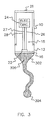
- FIG. 3 is an illustration of another exemplary embodiment showing an apparatus for measuring pressure.
- an elongated member 302 is attached to the pressure sensor having a squeezable distal portion 304. It is contemplated that the pressure sensor and the microelectronic device may be manufactured as an integrated piece or two separate pieces attached together. As described above, a contiguous chamber 15 is formed within the microelectronic device 10 and the pressure sensor 12, wherein the pressure therein is at the initial predetermined pressure.
- the elongated member comprises a body portion having a substantially non-expanding wall with incompressible fluid 306 therein which provides a medium for transferring any pressure imparted on the squeezable distal portion to the proximal end of the elongated member where it is in contact with the flexible portion/diaphragm of the pressure sensor.
- This embodiment provides for placement of the squeezable distal portion of the elongated member in areas of the body or an object where it is difficult to place the microelectronic device 10 with its associated pressure sensor 12.
- the elongated member can be implanted subcutaneously near the tip of the finger of a person and the microelectronic device 10 may be placed in palm of the hand of the person. In this manner, when the distal portion is squeezed when subjected to pressure, the incompressible fluid in the elongated member is pressurized and results in a change on the diaphragm of the pressure sensor.
- FIG. 4 is an illustration of an exemplary system utilizing the exemplary embodiments of the apparatus described above for measuring pressure.
- an external unit 402 is provided for communication with the apparatus that may be in the form of an implantable device 404.
- the external unit 402 broadly comprises a transmitter/receiver 406, wherein the transmitter is electrically coupled to an RF amplifier 408, RF oscillator 410, and control circuitry 412 for providing transmission of data communication containing command instructions to the implantable device 404.
- the external unit has the capability of providing power to the implantable device 404.
- the receiver of the external unit 402 is electrically coupled to at least an RF detector 414, a preamplifier 416, an A/D converter 418, and a measuring circuit 420 for providing a measurement of the pressure information received from the apparatus.
- the external unit 402 may also be implantable in a body.
- the implantable device 404 broadly comprises a transmitter/receiver 422, electronic circuitry 424, an A/D converter 426, an amplifier 428, and the pressure sensor 12. Referring to FIG. 4, in an embodiment of the system the implantable device 404 may be implanted under the skin i.e., subcutaneously, and adjacent to a desired blood vessel, lung, heart, skin pressure point, nerve or muscle for pressure sensing and/or stimulation in the body.
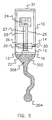
- FIG. 5 is an illustration of yet another exemplary embodiment of the apparatus shown in FIG. 3.
- the interface member 14 is positioned between the microelectronic device 10 and the pressure sensor 12 and attached thereto.
- the chamber or cavity 13 is formed within the pressure sensor 12 and between the diaphragm 16 and the interface member 14.
- the incompressible fluid 306 transfers the change in volume to the diaphragm 16 of the pressure sensor 12 which measures the imparted pressure change.
- the pressure in the cavity 13 is set at an initial predetermined pressure.
- any of the embodiments of the apparatus described herein may be implanted subcutaneously or percutaneously in a body of a living organism or placed on the surface of the body.
- the apparatus when the apparatus is implanted subcutaneously, it utilizes wireless communication although in some circumstances it may utilize wired communication with the external unit.
- the dimensions of the microelectronic device are less than about 100 mm and 10 mm longitudinally (axial) and laterally respectively and preferably 60 mm and 6 mm respectively. This provides for a more efficient injection of the apparatus into the body.
- the pressure sensor signal may be AC-coupled to the electronic circuitry in the microelectronic device as an example of a technique to monitor rapid pressure changes sensed by a microelectronic device but ignore very slow changes in pressure.
- this technique is applicable for determining whether a person is walking by having the apparatus implanted in the foot of the person.
- the AC-coupled pressure sensor provides, for example, a voltage for charging an AC-coupled capacitor and when the person lifts his or her foot off the ground the capacitor discharges at a specific rate. If the pressure changes at a rate slower than the discharge rate, the capacitor would not be charged up.
- the pressure on the capacitor can be detected.
- Yet another application of the AC-coupling is for compensating for gradual changes in the atmospheric pressure surrounding the apparatus.
- the apparatus having the internal initial predetermined pressure of, for example, one (1) atmospheric pressure at sea level is displaced to a higher altitude, the diaphragm will be deformed by bulging outward to equalize the internal pressure with the surrounding pressure.
- the strain gauge will be deformed and will provide a voltage change that is translated into a pressure measurement.
- the desired pressure measurement is the pressure inside a patient's body or an inanimate object, the effects of the change in altitude could provide a potentially false measurement.
- the AC-coupling of the electronic circuitry in the microelectronic device to the pressure sensor compensates for the potentially false measurement by allowing relatively more rapid changes in pressure (such as stepping as described above) to be detected by the apparatus in such a way that is independent of a gradual change in pressure due to a change in altitude.
- Another approach for compensating or correcting for a change in pressure due to altitude or weather systems is to provide a secondary pressure sensor means 421 (such as a barometer or another apparatus similar and consistent with the exemplary embodiments of the apparatus described herein) associated with the external unit 402 such that the secondary pressure sensor means measures the surrounding environment's atmospheric pressure.
- the surrounding environment's atmospheric pressure may be communicated through the external unit to the apparatus as a reference pressure.
- the apparatus can correctly measure a desired pressure by comparing the reference pressure with the total pressure sensed by it.
Abstract
Description
- This application claims the benefit of U.S. Provisional Application No. 60/497,391 filed on August 22, 2003 and said U.S. Provisional Application No. 60/497,391 is hereby incorporated by reference herein.
- The invention in various aspects, and preferred and optional features, are set out in the claims.
-
- FIG. 1 is an illustration of an exemplary embodiment showing an apparatus for measuring pressure.
- FIG. 2 is an exemplary representation of a wheatstone bridge circuit arrangement suitable for measuring pressure.
- FIG. 3 is an illustration of another exemplary embodiment showing an apparatus for measuring pressure.
- FIG. 4 is an illustration of an exemplary system utilizing the apparatus for measuring pressure.
- FIG. 5 is an illustration of yet another exemplary embodiment of the apparatus shown in FIG. 3.
-
- In accordance with an exemplary embodiment, an apparatus for measuring pressure in association with a living organism or inanimate object is described. The apparatus comprises at least a microelectronic device and a pressure sensor connected thereto. In some circumstances, an interface member may be disposed between the microelectronic device and the pressure sensor. The microelectronic device can be a microstimulator and/or a microsensor. For example, a class of injectable/implantable microelectronic devices described in U.S. Patent Nos. 5,193,539, 5,193,540, 5,312,439, 6,164,284, 6,185,452, 6,208,894, 6,315,721, 6,564,807 and incorporated by reference herein provide for stimulation of biological tissue or sensing of signals from biological tissue such as nerves or muscles as well as physiologic parameters such as body temperature. Each device includes electrical stimulation circuitry and electrodes configured in a form that is suitable for injection by means of a hypodermic needle or insertion tool. The devices can be leadless or have leads attached to them. Furthermore, each device may communicate through wireless or wired communication networks. In the case of wireless networks, microelectronic devices receive power by either inductive coupling to an externally applied electro-magnetic field or by means of an internal rechargeable battery as described in U.S. Pat. No. 6,208,894. They receive digital command signals by telemetry. The packaging and materials of the microelectronic device are selected and designed to protect its electronic circuitry from the body fluids and to avoid damage to the electrodes and the surrounding tissues from the presence and operation of the microelectronic device in those tissues. In this regard the microelectronic devices are hermetically sealed and unaffected by body fluids.
- FIG. 1 is an illustration of an exemplary embodiment showing an apparatus for measuring pressure. A
microelectronic device 10 is connected to apressure sensor 12 allowing for measurement of pressure associated with any portions of a living organism or inanimate object or environment in the immediate proximity ofpressure sensor 12. The living organism may be, among others, a human or an animal, and the inanimate object may be, for example, a vehicle tire or any other equipment that require a pressure measurement. An interface member 14 (shown in dotted lines) may be optionally disposed between themicroelectronic device 10 and thepressure sensor 12. Thepressure sensor 12 has a flexible portion in a form of adiaphragm 16. There is formed a hermetically sealedcavity 13 within thepressure sensor 12 and between thediaphragm 16 and theinterface member 14. It is contemplated that the pressure in the hermetically sealedcavity 13 is set at an initial predetermined pressure. This initial predetermined pressure may be about one (1) atmosphere or any other desired pressure. Thepressure sensor 12 may be releasably attached to the microelectronic device or the interface member, or alternatively it may be manufactured as an integrated piece with the microelectronic device or the interface member. Generally, the microelectronic device may be made of ceramic such as zirconia or alumina and the pressure sensor may be made of titanium or titanium alloy. The interface member can be made of, for example, titanium. Thediaphragm 16 is responsive to the external pressure exerted thereon. For example, when the external pressure is higher than one-atmosphere, then thediaphragm 16 is pressed inward and creates a deformation which can be utilized to measure the external pressure. One of a number of techniques is to utilize a strain gauge mounted on thediaphragm 16 so that to measure the external pressure. Once the strain gauge is deformed, corresponding voltage changes produced by the gauge may be detected and calibrated as a function of pressure. - It is contemplated that the
interface member 14 is connected to themicroelectronic device 10 and the pressure sensor through various other attachment techniques such as brazing, soldering, welding, gluing, or other techniques known to those skilled in the relevant art. For example, when brazing theinterface member 14 tomicroelectronic device 10, nickel or a nickel alloy may be used as the braze material. The pressure sensor is hermetically sealed through various techniques known to those skilled in the art in order to maintain a completely sealed cavity as part of the pressure sensor. To convey electrical signals from thestrain gauge 22 tomicroelectronic device electronics 24 for processing, vias (wires) 26, 27 and 28 (and more if required) are arranged to extend through interface member hermetic feed-through 30, 31 and 32 respectively toelectronics 24. To maintain hermeticity, laser welding technology may be used to seal the feed-throughs once thewires 26,27and 28 have been connected through the feed-throughs. It is further contemplated that the pressure sensor and the interface member may be a single-unit integrated piece. - Mere examples of pressure sensors contemplated for use in the embodiments of the invention are strain gauges, piezoelectric crystals, or any other sensors known to those skilled in the art that produce an output signal as a function of pressure or strain related mechanical disturbances to the sensor. The pressure sensor can be positioned on either the stimulating/active electrode end or the
indifferent electrode end 21 of the microelectronic device. Referring to FIG. 1, when thepressure sensor 12 is positioned on the stimulating electrode end of the microelectronic device, the diaphragm of the pressure sensor can be made electrically conductive in order to maintain proper electrical conductivity for stimulation of a desired nerve or muscle. To provide adequate electrical conductivity various techniques such as sputtering may be utilized for adhering or depositing electricallyconductive material 20 such as, for example, platinum, and iridium onto the surface of thepressure sensor diaphragm 16. In the alternative, a pressure sensor may be provided where its diaphragm is made of an electrically conductive material suitable for delivering electrical stimulation pulses to selected sites. - In an embodiment wherein it is desired not to have an interface member between the microelectronic device and the pressure sensor, preferably the pressure in a chamber formed by the microelectronic device and the pressure sensor should be set at the initial predetermined pressure. In order to prevent the pressure inside the chamber from changing because of the gas absorption or emission characteristic of the internal components in the microelectronic device, it is contemplated that the internal components used in the microelectronic device are made of non-gas emissive and non-gas absorbing material. The gas used in the contiguous space/chamber may be any type of inert gas such as argon. Furthermore, it is contemplated that the pressure in the contiguous space/chamber between the pressure sensor and the microelectronic device is calibrated to about one-atmosphere.
- FIG. 2 is an exemplary representation of a Wheatstone Bridge circuit arrangement as part of a strain gauge suitable for measuring pressure. For example, as described above, various types of pressure sensors such as a strain gauge, among others, may be utilized with the microelectronic device. By way of illustration, under pressure changes, the strain gauge flexes such that the resistance values of R1, R2, R3, and R4 or any combination of them (depending on whether a quarter-bridge, half-bridge, or full-bridge is implemented) are changed in proportion to the sensed changing pressure condition. The change in the resistance values results in a change in the voltage value between the
nodes operational amplifier 206 which amplifies the differential signal representative of a sensed pressure. The differential signal is further provided to an analog-to-digital (A/D) converter in the microelectronic device for signal conversion and subsequent transmission to an external unit described in further detail below. - FIG. 3 is an illustration of another exemplary embodiment showing an apparatus for measuring pressure. In this embodiment, an
elongated member 302 is attached to the pressure sensor having a squeezabledistal portion 304. It is contemplated that the pressure sensor and the microelectronic device may be manufactured as an integrated piece or two separate pieces attached together. As described above, acontiguous chamber 15 is formed within themicroelectronic device 10 and thepressure sensor 12, wherein the pressure therein is at the initial predetermined pressure. The elongated member comprises a body portion having a substantially non-expanding wall withincompressible fluid 306 therein which provides a medium for transferring any pressure imparted on the squeezable distal portion to the proximal end of the elongated member where it is in contact with the flexible portion/diaphragm of the pressure sensor. This embodiment provides for placement of the squeezable distal portion of the elongated member in areas of the body or an object where it is difficult to place themicroelectronic device 10 with its associatedpressure sensor 12. For example, the elongated member can be implanted subcutaneously near the tip of the finger of a person and themicroelectronic device 10 may be placed in palm of the hand of the person. In this manner, when the distal portion is squeezed when subjected to pressure, the incompressible fluid in the elongated member is pressurized and results in a change on the diaphragm of the pressure sensor. - FIG. 4 is an illustration of an exemplary system utilizing the exemplary embodiments of the apparatus described above for measuring pressure. In this
system 400, anexternal unit 402 is provided for communication with the apparatus that may be in the form of an implantable device 404. As shown in FIG. 4, theexternal unit 402 broadly comprises a transmitter/receiver 406, wherein the transmitter is electrically coupled to anRF amplifier 408,RF oscillator 410, andcontrol circuitry 412 for providing transmission of data communication containing command instructions to the implantable device 404. Although not shown, the external unit has the capability of providing power to the implantable device 404. The receiver of theexternal unit 402 is electrically coupled to at least an RF detector 414, apreamplifier 416, an A/D converter 418, and a measuringcircuit 420 for providing a measurement of the pressure information received from the apparatus. It should be noted that theexternal unit 402 may also be implantable in a body. The implantable device 404 broadly comprises a transmitter/receiver 422,electronic circuitry 424, an A/D converter 426, anamplifier 428, and thepressure sensor 12. Referring to FIG. 4, in an embodiment of the system the implantable device 404 may be implanted under the skin i.e., subcutaneously, and adjacent to a desired blood vessel, lung, heart, skin pressure point, nerve or muscle for pressure sensing and/or stimulation in the body. - FIG. 5 is an illustration of yet another exemplary embodiment of the apparatus shown in FIG. 3. In this embodiment, the
interface member 14 is positioned between themicroelectronic device 10 and thepressure sensor 12 and attached thereto. As described above, the chamber orcavity 13 is formed within thepressure sensor 12 and between thediaphragm 16 and theinterface member 14. Identical to the arrangement and the operation described in connection with the exemplary embodiment shown in FIG. 3, by applying pressure to the squeezabledistal portion 304 theincompressible fluid 306 transfers the change in volume to thediaphragm 16 of thepressure sensor 12 which measures the imparted pressure change. Furthermore, as described in FIG. 1, the pressure in thecavity 13 is set at an initial predetermined pressure. - It should be noted that any of the embodiments of the apparatus described herein may be implanted subcutaneously or percutaneously in a body of a living organism or placed on the surface of the body. Generally, when the apparatus is implanted subcutaneously, it utilizes wireless communication although in some circumstances it may utilize wired communication with the external unit. The dimensions of the microelectronic device are less than about 100 mm and 10 mm longitudinally (axial) and laterally respectively and preferably 60 mm and 6 mm respectively. This provides for a more efficient injection of the apparatus into the body.
- In any of the embodiments described herein, the pressure sensor signal may be AC-coupled to the electronic circuitry in the microelectronic device as an example of a technique to monitor rapid pressure changes sensed by a microelectronic device but ignore very slow changes in pressure. For example, this technique is applicable for determining whether a person is walking by having the apparatus implanted in the foot of the person. In this manner, when the person sets his or her foot on the ground, the AC-coupled pressure sensor provides, for example, a voltage for charging an AC-coupled capacitor and when the person lifts his or her foot off the ground the capacitor discharges at a specific rate. If the pressure changes at a rate slower than the discharge rate, the capacitor would not be charged up. If the pressure charges at a rate faster than the discharge rate, then the voltage on the capacitor can be detected. Yet another application of the AC-coupling is for compensating for gradual changes in the atmospheric pressure surrounding the apparatus. By way of example, when the apparatus having the internal initial predetermined pressure of, for example, one (1) atmospheric pressure at sea level is displaced to a higher altitude, the diaphragm will be deformed by bulging outward to equalize the internal pressure with the surrounding pressure. As a result, the strain gauge will be deformed and will provide a voltage change that is translated into a pressure measurement. In instances where the desired pressure measurement is the pressure inside a patient's body or an inanimate object, the effects of the change in altitude could provide a potentially false measurement. The AC-coupling of the electronic circuitry in the microelectronic device to the pressure sensor compensates for the potentially false measurement by allowing relatively more rapid changes in pressure (such as stepping as described above) to be detected by the apparatus in such a way that is independent of a gradual change in pressure due to a change in altitude.
- Another approach for compensating or correcting for a change in pressure due to altitude or weather systems is to provide a secondary pressure sensor means 421 (such as a barometer or another apparatus similar and consistent with the exemplary embodiments of the apparatus described herein) associated with the
external unit 402 such that the secondary pressure sensor means measures the surrounding environment's atmospheric pressure. The surrounding environment's atmospheric pressure may be communicated through the external unit to the apparatus as a reference pressure. Hence, the apparatus can correctly measure a desired pressure by comparing the reference pressure with the total pressure sensed by it. - While the invention has been described by means of specific embodiments and applications thereof, it is understood that numerous modifications and variations could be made thereto by those skilled in the art without departing from the spirit and scope of the invention.
Claims (43)
- An apparatus for measuring pressure, comprising:wherein the interface member is positioned between the microelectronic device and the pressure sensor and is attached to the pressure sensor providing a first cavity between the pressure sensor diaphragm and the interface member and wherein the pressure in the first cavity is set at an initial predetermined pressure.a microelectronic device;an interface member attached to the microelectronic device;a pressure sensor having a diaphragm responsive to external pressure exerted upon the diaphragm;
- The apparatus of claim 1, wherein the microelectronic device is less than 100 mm in longitudinal dimension and less than 10 mm in lateral dimension.
- The apparatus of claim 1 or 2, wherein the initial predetermined pressure is about 1 atmosphere.
- The apparatus of claim 1, 2 or 3, wherein the interface member has at least one feed-through passageway and the pressure sensor provides electrical signals to the microelectronic device through the at least one feed-through passageway.
- The apparatus of claim 4, wherein the interface member forms a hermetically sealed cavity with the pressure sensor.
- The apparatus of any one of claims 1 to 5, wherein the microelectronic device is a microstimulator or a microsensor.
- The apparatus of any one of claims 1 to 6, wherein the pressure sensor is releasably attached to the interface member or is integrated with the interface member.
- The apparatus of any one of claims 1 to 7, wherein the microelectronic device is adapted to be implanted in a living organism or is adapted for percutaneous attachment to a living organism.
- The apparatus of claim 1, wherein the pressure sensor includes electrically conductive material.
- The apparatus of claim 9, wherein the electrically conductive material is selected from the group consisting of:iridium, platinum and a combination thereof.
- The apparatus of claim 9 or 10, wherein the electrically conductive material is deposited on the surface of the pressure sensor.
- The apparatus of claim 9, 10 or 11, wherein the pressure sensor is substantially made of titanium alloy.
- The apparatus of any one of claims 1 to 12, wherein the pressure sensor is AC coupled to the microelectronic device to detect rapid pressure changes.
- The apparatus of any one of claims 1 to 13, wherein the pressure sensor is a piezoelectric sensor or is a strain gauge sensor.
- An apparatus for measuring pressure, comprising:wherein the elongated member contains incompressible fluid therein.a microelectronic device;a pressure sensor comprising a diaphragm responsive to external pressure exerted upon the diaphragm, wherein the pressure sensor is attached to the microelectronic device, wherein a contiguous chamber is formed within the microelectronic device and the pressure sensor and wherein the pressure in the chamber is set at an initial predetermined pressure, andan elongated member attached and in contact with the diaphragm of the pressure sensor, wherein the elongated member comprises a body portion having a substantially non-expandable wall and a squeezable distal portion and
- The apparatus of claim 15, wherein the microelectronic device is less than 100 mm in longitudinal dimension and less than 10 mm in lateral dimension.
- The apparatus of claim 15 or 16, wherein the initial predetermined pressure is about 1 atmosphere.
- The apparatus of claim 15, 16 or 17, further comprising:an interface member positioned between the microelectronic device and the pressure sensor.
- The apparatus of any one of claims 15 to 18, wherein the microelectronic device is a microstimulator or is a microsensor.
- The apparatus of claim 18 or 19, wherein the pressure sensor is releasably attached to the microelectronic device or is integrated with the microelectronic device.
- The apparatus of any one of claims 15 to 20, wherein the microelectronic device is adapted to be implanted in a living organism, is adapted for percutaneous attachment to a living organism or is adapted for subcutaneous implantation in a living organism.
- The apparatus of any one of claims 15 to 21, wherein the pressure sensor is hermetically sealed.
- The apparatus of any one of claims 15 to 22, wherein the pressure sensor is AC coupled to the microelectronic device.
- A system for measuring pressure sensed by an implantable device, comprising:wherein the interface member is positioned between the microelectronic device and the pressure sensor providing a first cavity between the pressure sensor flexible portion and the interface member and wherein the pressure in the cavity is set at an initial predetermined pressure; andan implantable device, comprising:a microelectronic device;an interface member;a pressure sensor having a flexible portion responsive to pressure exerted upon the flexible portion;
an external unit for communicating with the implantable device. - The system of claim 24, wherein the external unit and the implantable device communicate through a wireless medium.
- The system of claim 25, wherein the external unit and the implantable device are adapted to provide data communication therebetween.
- The system of claim 26, wherein the external unit is further adapted to provide power to the implantable device.
- The system of any one of claims 24 to 27, wherein the initial predetermined pressure is about 1 atmosphere.
- The system of any one of claims 24 to 28, wherein the external unit comprises a secondary pressure sensor means for measuring the pressure surrounding said external unit and providing thereby a reference pressure to the external unit or the implantable device for measuring the pressure sensed by the implantable device.
- An apparatus for measuring pressure, comprising:a microelectronic device;a pressure sensor having a flexible portion responsive to external pressure exerted upon the flexible portion, wherein the pressure sensor is attached to the microelectronic device providing a contiguous chamber within the pressure sensor and the microelectronic device, wherein the pressure in the contiguous chamber is set at an initial predetermined pressure.
- The apparatus of claim 30, wherein the microelectronic device comprises: internal components made of non-gas emissive and non-gas absorbing material.
- The apparatus of claim 30 or 31, wherein the initial predetermined pressure is about 1 atmosphere.
- The apparatus of claim 30, 31 or 32, wherein the microelectronic device is less than 100 mm in longitudinal dimension and less than 10 mm in lateral dimension.
- The apparatus of any one of claims 30 to 33, wherein the interface member forms a hermetically sealed cavity with the pressure sensor wherein the pressure in the hermetically sealed cavity is set at the initial predetermined pressure.
- The apparatus of any one of claims 30 to 34, wherein the microelectronic device is a microstimulator.
- The apparatus of any one of claims 30 to 35, wherein the pressure sensor is releasably attached to the interface member or is integrated with the interface member.
- The apparatus of any one of claims 30 to 36, wherein the microelectronic device is adapted to implanted in a living organism or is adapted for percutaneous attachment to a living organism.
- The apparatus of any one of claims 30 to 37, wherein the pressure sensor includes electrically conductive material.
- The apparatus of claim 38, wherein the electrically conductive material is selected from the group consisting of:iridium, platinum and a combination thereof.
- The apparatus of claim 38 or 39, wherein the electrically conductive material is deposited on the surface of the pressure sensor.
- The apparatus of claim 38, wherein the pressure sensor is substantially made of titanium alloy.
- The apparatus of any one of claims 30 to 41, wherein the pressure sensor is AC coupled to the microelectronic device.
- The apparatus of any one of claims 30 to 42, wherein the pressure sensor is a piezoelectric sensor or is a strain gauge sensor.
Priority Applications (1)
| Application Number | Priority Date | Filing Date | Title |
|---|---|---|---|
| EP08011763A EP1969998A3 (en) | 2003-08-22 | 2004-08-20 | System and apparatus for sensing pressure in living organisms and inanimate objects |
Applications Claiming Priority (2)
| Application Number | Priority Date | Filing Date | Title |
|---|---|---|---|
| US49739103P | 2003-08-22 | 2003-08-22 | |
| US497391P | 2003-08-22 |
Related Child Applications (1)
| Application Number | Title | Priority Date | Filing Date |
|---|---|---|---|
| EP08011763A Division EP1969998A3 (en) | 2003-08-22 | 2004-08-20 | System and apparatus for sensing pressure in living organisms and inanimate objects |
Publications (2)
| Publication Number | Publication Date |
|---|---|
| EP1508295A1 true EP1508295A1 (en) | 2005-02-23 |
| EP1508295B1 EP1508295B1 (en) | 2008-12-17 |
Family
ID=34062169
Family Applications (2)
| Application Number | Title | Priority Date | Filing Date |
|---|---|---|---|
| EP08011763A Ceased EP1969998A3 (en) | 2003-08-22 | 2004-08-20 | System and apparatus for sensing pressure in living organisms and inanimate objects |
| EP04255014A Active EP1508295B1 (en) | 2003-08-22 | 2004-08-20 | System and apparatus for sensing pressure in living organisms and inanimate objects |
Family Applications Before (1)
| Application Number | Title | Priority Date | Filing Date |
|---|---|---|---|
| EP08011763A Ceased EP1969998A3 (en) | 2003-08-22 | 2004-08-20 | System and apparatus for sensing pressure in living organisms and inanimate objects |
Country Status (5)
| Country | Link |
|---|---|
| US (2) | US7252005B2 (en) |
| EP (2) | EP1969998A3 (en) |
| AT (1) | ATE417544T1 (en) |
| DE (1) | DE602004018437D1 (en) |
| ES (1) | ES2319650T3 (en) |
Cited By (2)
| Publication number | Priority date | Publication date | Assignee | Title |
|---|---|---|---|---|
| WO2011039486A3 (en) * | 2009-09-30 | 2011-07-07 | Societe De Technologie Michelin | Sealed pressure-measuring member |
| EP2836115B1 (en) * | 2012-04-13 | 2024-04-03 | Branchpoint Technologies, Inc. | Sensor and circuitry for wireless intracranial pressure monitoring |
Families Citing this family (48)
| Publication number | Priority date | Publication date | Assignee | Title |
|---|---|---|---|---|
| US20050204824A1 (en) * | 2004-03-22 | 2005-09-22 | Goodman Daniel A | Device and system for pressure sensing and control |
| US8388553B2 (en) | 2004-11-04 | 2013-03-05 | Smith & Nephew, Inc. | Cycle and load measurement device |
| US7775966B2 (en) | 2005-02-24 | 2010-08-17 | Ethicon Endo-Surgery, Inc. | Non-invasive pressure measurement in a fluid adjustable restrictive device |
| US7699770B2 (en) | 2005-02-24 | 2010-04-20 | Ethicon Endo-Surgery, Inc. | Device for non-invasive measurement of fluid pressure in an adjustable restriction device |
| US7775215B2 (en) | 2005-02-24 | 2010-08-17 | Ethicon Endo-Surgery, Inc. | System and method for determining implanted device positioning and obtaining pressure data |
| US8016744B2 (en) | 2005-02-24 | 2011-09-13 | Ethicon Endo-Surgery, Inc. | External pressure-based gastric band adjustment system and method |
| US7658196B2 (en) | 2005-02-24 | 2010-02-09 | Ethicon Endo-Surgery, Inc. | System and method for determining implanted device orientation |
| US8066629B2 (en) | 2005-02-24 | 2011-11-29 | Ethicon Endo-Surgery, Inc. | Apparatus for adjustment and sensing of gastric band pressure |
| US7927270B2 (en) | 2005-02-24 | 2011-04-19 | Ethicon Endo-Surgery, Inc. | External mechanical pressure sensor for gastric band pressure measurements |
| US7866964B2 (en) * | 2005-05-20 | 2011-01-11 | Emerson Climate Technologies, Inc. | Sensor for hermetic machine |
| JP5518335B2 (en) | 2005-08-23 | 2014-06-11 | スミス アンド ネフュー インコーポレーテッド | Telemetric orthopedic implant |
| US8152710B2 (en) | 2006-04-06 | 2012-04-10 | Ethicon Endo-Surgery, Inc. | Physiological parameter analysis for an implantable restriction device and a data logger |
| US8870742B2 (en) | 2006-04-06 | 2014-10-28 | Ethicon Endo-Surgery, Inc. | GUI for an implantable restriction device and a data logger |
| US9445720B2 (en) * | 2007-02-23 | 2016-09-20 | Smith & Nephew, Inc. | Processing sensed accelerometer data for determination of bone healing |
| ITMI20070844A1 (en) * | 2007-04-23 | 2008-10-24 | Istituto Ortopedico Galeazzi Spa | DEVICE FOR DETECTION OF ARTICULAR FORCES |
| US8262372B2 (en) | 2007-05-10 | 2012-09-11 | Emerson Climate Technologies, Inc. | Compressor hermetic terminal |
| US8939734B2 (en) * | 2007-08-28 | 2015-01-27 | Emerson Climate Technologies, Inc. | Molded plug for a compressor |
| JP6121088B2 (en) | 2007-09-06 | 2017-04-26 | スミス アンド ネフュー インコーポレイテッド | System and method for communicating with a telemetric implant |
| US8187163B2 (en) | 2007-12-10 | 2012-05-29 | Ethicon Endo-Surgery, Inc. | Methods for implanting a gastric restriction device |
| US8100870B2 (en) | 2007-12-14 | 2012-01-24 | Ethicon Endo-Surgery, Inc. | Adjustable height gastric restriction devices and methods |
| US8142452B2 (en) | 2007-12-27 | 2012-03-27 | Ethicon Endo-Surgery, Inc. | Controlling pressure in adjustable restriction devices |
| US8377079B2 (en) | 2007-12-27 | 2013-02-19 | Ethicon Endo-Surgery, Inc. | Constant force mechanisms for regulating restriction devices |
| US8192350B2 (en) | 2008-01-28 | 2012-06-05 | Ethicon Endo-Surgery, Inc. | Methods and devices for measuring impedance in a gastric restriction system |
| US8337389B2 (en) | 2008-01-28 | 2012-12-25 | Ethicon Endo-Surgery, Inc. | Methods and devices for diagnosing performance of a gastric restriction system |
| US8591395B2 (en) | 2008-01-28 | 2013-11-26 | Ethicon Endo-Surgery, Inc. | Gastric restriction device data handling devices and methods |
| US7844342B2 (en) | 2008-02-07 | 2010-11-30 | Ethicon Endo-Surgery, Inc. | Powering implantable restriction systems using light |
| US8221439B2 (en) | 2008-02-07 | 2012-07-17 | Ethicon Endo-Surgery, Inc. | Powering implantable restriction systems using kinetic motion |
| US8114345B2 (en) | 2008-02-08 | 2012-02-14 | Ethicon Endo-Surgery, Inc. | System and method of sterilizing an implantable medical device |
| US8057492B2 (en) | 2008-02-12 | 2011-11-15 | Ethicon Endo-Surgery, Inc. | Automatically adjusting band system with MEMS pump |
| US8591532B2 (en) | 2008-02-12 | 2013-11-26 | Ethicon Endo-Sugery, Inc. | Automatically adjusting band system |
| US8034065B2 (en) | 2008-02-26 | 2011-10-11 | Ethicon Endo-Surgery, Inc. | Controlling pressure in adjustable restriction devices |
| US8187162B2 (en) | 2008-03-06 | 2012-05-29 | Ethicon Endo-Surgery, Inc. | Reorientation port |
| US8233995B2 (en) | 2008-03-06 | 2012-07-31 | Ethicon Endo-Surgery, Inc. | System and method of aligning an implantable antenna |
| EP2158840B1 (en) | 2008-08-27 | 2014-09-10 | Biotronik CRM Patent AG | Implantable biosensor and sensor assembly |
| US8704124B2 (en) | 2009-01-29 | 2014-04-22 | Smith & Nephew, Inc. | Low temperature encapsulate welding |
| US8939735B2 (en) * | 2009-03-27 | 2015-01-27 | Emerson Climate Technologies, Inc. | Compressor plug assembly |
| US8071830B1 (en) | 2009-06-29 | 2011-12-06 | Uop Llc | Process for alkylation of aromatic hydrocarbons using UZM-35 |
| US9314175B2 (en) * | 2010-07-08 | 2016-04-19 | TCI3—Pressure Applications, LLC | Compartment syndrome monitoring systems and methods |
| TWI453974B (en) * | 2012-02-22 | 2014-09-21 | Nat Univ Chung Hsing | Chargeable battery inside organism and charging apparatus thereof |
| US9480177B2 (en) | 2012-07-27 | 2016-10-25 | Emerson Climate Technologies, Inc. | Compressor protection module |
| CN103110414A (en) * | 2012-12-21 | 2013-05-22 | 西安交通大学 | Full-bridge chip embedded skull pressure sensor |
| CN103040456B (en) * | 2012-12-21 | 2015-07-08 | 西安交通大学 | Half-bridge chip planted type intracranial pressure sensor |
| US9126009B2 (en) * | 2013-03-12 | 2015-09-08 | DePuy Synthes Products, Inc. | System and method for determining position and pressure of an implantable shunt |
| EP2865326A1 (en) * | 2013-10-25 | 2015-04-29 | Sinvent AS | In-vivo pressure monitoring system |
| EP3838131A3 (en) | 2014-04-17 | 2021-12-15 | Branchpoint Technologies, Inc. | Wireless intracranial monitoring system |
| US9901269B2 (en) | 2014-04-17 | 2018-02-27 | Branchpoint Technologies, Inc. | Wireless intracranial monitoring system |
| EP3389489B1 (en) * | 2015-12-18 | 2022-04-13 | Dropnostix GmbH | Device for measuring the gastric pressure and the gastric motility of a livestock animal |
| DE102020200213A1 (en) * | 2019-12-04 | 2021-06-10 | Siemens Aktiengesellschaft | Multifunctional sensor for the process industry |
Citations (18)
| Publication number | Priority date | Publication date | Assignee | Title |
|---|---|---|---|---|
| US3703099A (en) * | 1969-11-12 | 1972-11-21 | Ici Ltd | Pressure transducer |
| US3748623A (en) * | 1972-07-25 | 1973-07-24 | Millar Instruments | Pressure transducers |
| US3835864A (en) * | 1970-09-21 | 1974-09-17 | Rasor Ass Inc | Intra-cardiac stimulator |
| US4127110A (en) * | 1976-05-24 | 1978-11-28 | Huntington Institute Of Applied Medical Research | Implantable pressure transducer |
| US5193539A (en) | 1991-12-18 | 1993-03-16 | Alfred E. Mann Foundation For Scientific Research | Implantable microstimulator |
| US5193540A (en) | 1991-12-18 | 1993-03-16 | Alfred E. Mann Foundation For Scientific Research | Structure and method of manufacture of an implantable microstimulator |
| US5312439A (en) | 1991-12-12 | 1994-05-17 | Loeb Gerald E | Implantable device having an electrolytic storage electrode |
| US5538005A (en) * | 1993-06-25 | 1996-07-23 | The Regents Of The University Of California | B'method for monitoring fetal characteristics by radiotelemetric transmission |
| US5772575A (en) * | 1995-09-22 | 1998-06-30 | S. George Lesinski | Implantable hearing aid |
| US6164284A (en) | 1997-02-26 | 2000-12-26 | Schulman; Joseph H. | System of implantable devices for monitoring and/or affecting body parameters |
| US6185452B1 (en) | 1997-02-26 | 2001-02-06 | Joseph H. Schulman | Battery-powered patient implantable device |
| US6208894B1 (en) | 1997-02-26 | 2001-03-27 | Alfred E. Mann Foundation For Scientific Research And Advanced Bionics | System of implantable devices for monitoring and/or affecting body parameters |
| US6269269B1 (en) * | 1998-04-23 | 2001-07-31 | Medtronic Inc. | Method and apparatus for synchronized treatment of obstructive sleep apnea |
| US20020049394A1 (en) * | 2000-08-25 | 2002-04-25 | The Cleveland Clinic Foundation | Apparatus and method for assessing loads on adjacent bones |
| US6470754B1 (en) * | 1998-08-19 | 2002-10-29 | Wisconsin Alumni Research Foundation | Sealed capacitive pressure sensors |
| US6518084B1 (en) * | 1998-12-15 | 2003-02-11 | Fraunhofer-Gesellschaft Zur Foerderung Der Angewandten Forschung E.V. | Method of producing a micromechanical structure for a micro-electromechanical element |
| US6520014B1 (en) * | 1999-06-02 | 2003-02-18 | Austria Mikro Systeme International Aktiengesellschaft | Microsensor having a sensor device connected to an integrated circuit by a solder joint |
| US6552404B1 (en) * | 2001-04-17 | 2003-04-22 | Analog Devices, Inc. | Integratable transducer structure |
Family Cites Families (17)
| Publication number | Priority date | Publication date | Assignee | Title |
|---|---|---|---|---|
| US3748823A (en) | 1970-04-13 | 1973-07-31 | Mayer Kg | Device for filling of containers, particularly bags, with loose material |
| DE3910646A1 (en) * | 1989-04-01 | 1990-10-04 | Endress Hauser Gmbh Co | CAPACITIVE PRESSURE SENSOR AND METHOD FOR THE PRODUCTION THEREOF |
| DE4339155C2 (en) * | 1993-11-16 | 1997-04-24 | Hewlett Packard Gmbh | Method for presetting an anesthesia protocol data processing system |
| US6030851A (en) * | 1995-06-07 | 2000-02-29 | Grandmont; Paul E. | Method for overpressure protected pressure sensor |
| JP3737554B2 (en) | 1996-01-09 | 2006-01-18 | 株式会社東海理化電機製作所 | Catheter with sensor function |
| US6223081B1 (en) | 1996-03-28 | 2001-04-24 | Medtronic, Inc. | Implantable stimulus system having stimulus generator with pressure sensor and common lead for transmitting stimulus pulses to a body location and pressure signals from the body location to the stimulus generator |
| US6673022B1 (en) | 1999-08-20 | 2004-01-06 | Innerspace Medical, Inc. | Gas column pressure monitoring catheters |
| US6939299B1 (en) * | 1999-12-13 | 2005-09-06 | Kurt Petersen | Implantable continuous intraocular pressure sensor |
| EP1284782B1 (en) * | 2000-05-17 | 2005-07-20 | Cook Vascular Incorporated | Lead removal apparatus |
| US20050107738A1 (en) * | 2000-07-21 | 2005-05-19 | Slater Charles R. | Occludable intravascular catheter for drug delivery and method of using the same |
| US6536440B1 (en) * | 2000-10-17 | 2003-03-25 | Sony Corporation | Method and system for generating sensory data onto the human neural cortex |
| US6584357B1 (en) * | 2000-10-17 | 2003-06-24 | Sony Corporation | Method and system for forming an acoustic signal from neural timing difference data |
| DE10123082C1 (en) * | 2001-05-11 | 2003-01-16 | Friedrich-W Von Hackewitz | Roller body one-way rotation device has control elements displaced in dependence on rotation direction for moving roller into clamping position blocking rotation of inner ring |
| US6682490B2 (en) | 2001-12-03 | 2004-01-27 | The Cleveland Clinic Foundation | Apparatus and method for monitoring a condition inside a body cavity |
| US6890300B2 (en) * | 2002-08-27 | 2005-05-10 | Board Of Trustees Of Michigan State University | Implantable microscale pressure sensor system for pressure monitoring and management |
| US6964661B2 (en) * | 2003-04-02 | 2005-11-15 | Boston Scientific Scimed, Inc. | Endovenous ablation mechanism with feedback control |
| US7252006B2 (en) * | 2004-06-07 | 2007-08-07 | California Institute Of Technology | Implantable mechanical pressure sensor and method of manufacturing the same |
-
2004
- 2004-08-18 US US10/921,750 patent/US7252005B2/en active Active
- 2004-08-20 EP EP08011763A patent/EP1969998A3/en not_active Ceased
- 2004-08-20 EP EP04255014A patent/EP1508295B1/en active Active
- 2004-08-20 DE DE602004018437T patent/DE602004018437D1/en active Active
- 2004-08-20 ES ES04255014T patent/ES2319650T3/en active Active
- 2004-08-20 AT AT04255014T patent/ATE417544T1/en not_active IP Right Cessation
-
2007
- 2007-06-01 US US11/809,472 patent/US7418872B2/en active Active
Patent Citations (20)
| Publication number | Priority date | Publication date | Assignee | Title |
|---|---|---|---|---|
| US3703099A (en) * | 1969-11-12 | 1972-11-21 | Ici Ltd | Pressure transducer |
| US3835864A (en) * | 1970-09-21 | 1974-09-17 | Rasor Ass Inc | Intra-cardiac stimulator |
| US3748623A (en) * | 1972-07-25 | 1973-07-24 | Millar Instruments | Pressure transducers |
| US4127110A (en) * | 1976-05-24 | 1978-11-28 | Huntington Institute Of Applied Medical Research | Implantable pressure transducer |
| US5312439A (en) | 1991-12-12 | 1994-05-17 | Loeb Gerald E | Implantable device having an electrolytic storage electrode |
| US5193539A (en) | 1991-12-18 | 1993-03-16 | Alfred E. Mann Foundation For Scientific Research | Implantable microstimulator |
| US5193540A (en) | 1991-12-18 | 1993-03-16 | Alfred E. Mann Foundation For Scientific Research | Structure and method of manufacture of an implantable microstimulator |
| US5538005A (en) * | 1993-06-25 | 1996-07-23 | The Regents Of The University Of California | B'method for monitoring fetal characteristics by radiotelemetric transmission |
| US5772575A (en) * | 1995-09-22 | 1998-06-30 | S. George Lesinski | Implantable hearing aid |
| US6185452B1 (en) | 1997-02-26 | 2001-02-06 | Joseph H. Schulman | Battery-powered patient implantable device |
| US6164284A (en) | 1997-02-26 | 2000-12-26 | Schulman; Joseph H. | System of implantable devices for monitoring and/or affecting body parameters |
| US6208894B1 (en) | 1997-02-26 | 2001-03-27 | Alfred E. Mann Foundation For Scientific Research And Advanced Bionics | System of implantable devices for monitoring and/or affecting body parameters |
| US6315721B2 (en) | 1997-02-26 | 2001-11-13 | Alfred E. Mann Foundation For Scientific Research | System of implantable devices for monitoring and/or affecting body parameters |
| US6564807B1 (en) | 1997-02-26 | 2003-05-20 | Alfred E. Mann Foundation For Scientific Research | System of implantable devices for monitoring and/or affecting body parameters |
| US6269269B1 (en) * | 1998-04-23 | 2001-07-31 | Medtronic Inc. | Method and apparatus for synchronized treatment of obstructive sleep apnea |
| US6470754B1 (en) * | 1998-08-19 | 2002-10-29 | Wisconsin Alumni Research Foundation | Sealed capacitive pressure sensors |
| US6518084B1 (en) * | 1998-12-15 | 2003-02-11 | Fraunhofer-Gesellschaft Zur Foerderung Der Angewandten Forschung E.V. | Method of producing a micromechanical structure for a micro-electromechanical element |
| US6520014B1 (en) * | 1999-06-02 | 2003-02-18 | Austria Mikro Systeme International Aktiengesellschaft | Microsensor having a sensor device connected to an integrated circuit by a solder joint |
| US20020049394A1 (en) * | 2000-08-25 | 2002-04-25 | The Cleveland Clinic Foundation | Apparatus and method for assessing loads on adjacent bones |
| US6552404B1 (en) * | 2001-04-17 | 2003-04-22 | Analog Devices, Inc. | Integratable transducer structure |
Cited By (4)
| Publication number | Priority date | Publication date | Assignee | Title |
|---|---|---|---|---|
| WO2011039486A3 (en) * | 2009-09-30 | 2011-07-07 | Societe De Technologie Michelin | Sealed pressure-measuring member |
| AU2010302457B2 (en) * | 2009-09-30 | 2014-09-25 | Compagnie Générale Des Etablissements Michelin | Sealed pressure-measuring member |
| US9476789B2 (en) | 2009-09-30 | 2016-10-25 | Compagnie Generale Des Etablissements Michelin | Sealed pressure-measuring member |
| EP2836115B1 (en) * | 2012-04-13 | 2024-04-03 | Branchpoint Technologies, Inc. | Sensor and circuitry for wireless intracranial pressure monitoring |
Also Published As
| Publication number | Publication date |
|---|---|
| EP1969998A3 (en) | 2008-10-08 |
| DE602004018437D1 (en) | 2009-01-29 |
| ES2319650T3 (en) | 2009-05-11 |
| US20070234815A1 (en) | 2007-10-11 |
| EP1969998A2 (en) | 2008-09-17 |
| US20050061079A1 (en) | 2005-03-24 |
| US7252005B2 (en) | 2007-08-07 |
| EP1508295B1 (en) | 2008-12-17 |
| ATE417544T1 (en) | 2009-01-15 |
| US7418872B2 (en) | 2008-09-02 |
Similar Documents
| Publication | Publication Date | Title |
|---|---|---|
| US7418872B2 (en) | System and apparatus for sensing pressure in living organisms and inanimate objects | |
| US6171252B1 (en) | Pressure sensor with increased sensitivity for use with an implantable medical device | |
| US9744282B2 (en) | Smart tip LVAD inlet cannula | |
| US6712772B2 (en) | Low power consumption implantable pressure sensor | |
| US6248080B1 (en) | Intracranial monitoring and therapy delivery control device, system and method | |
| US6922592B2 (en) | Implantable medical device controlled by a non-invasive physiological data measurement device | |
| US5564434A (en) | Implantable capacitive absolute pressure and temperature sensor | |
| EP0080347B1 (en) | Implantable dynamic pressure transducer system | |
| JP2786943B2 (en) | Implantable capacitive absolute pressure and temperature monitoring system | |
| EP0178528B1 (en) | Method for adjusting heart/pacer rate relative to right ventricular systolic pressure to obtain a required cardiac output | |
| US7203551B2 (en) | Implantable lead-based sensor powered by piezoelectric transformer | |
| US8460198B2 (en) | Implant transmitter | |
| US20090024054A1 (en) | Implantable medical device | |
| WO2004073513A3 (en) | Implantable medical device for assessing heart failure | |
| CN109890458A (en) | Implantable medical device with pressure sensor | |
| EP1578247B1 (en) | Low power consumption implantable pressure sensor | |
| US20170202513A1 (en) | Implantable pressure sensors and medical devices | |
| US8209031B1 (en) | Implantable lead for measuring physiologic information |
Legal Events
| Date | Code | Title | Description |
|---|---|---|---|
| PUAI | Public reference made under article 153(3) epc to a published international application that has entered the european phase |
Free format text: ORIGINAL CODE: 0009012 |
|
| AK | Designated contracting states |
Kind code of ref document: A1 Designated state(s): AT BE BG CH CY CZ DE DK EE ES FI FR GB GR HU IE IT LI LU MC NL PL PT RO SE SI SK TR |
|
| AX | Request for extension of the european patent |
Extension state: AL HR LT LV MK |
|
| 17P | Request for examination filed |
Effective date: 20050603 |
|
| AKX | Designation fees paid |
Designated state(s): AT BE BG CH CY CZ DE DK EE ES FI FR GB GR HU IE IT LI LU MC NL PL PT RO SE SI SK TR |
|
| 17Q | First examination report despatched |
Effective date: 20050912 |
|
| GRAP | Despatch of communication of intention to grant a patent |
Free format text: ORIGINAL CODE: EPIDOSNIGR1 |
|
| GRAS | Grant fee paid |
Free format text: ORIGINAL CODE: EPIDOSNIGR3 |
|
| GRAA | (expected) grant |
Free format text: ORIGINAL CODE: 0009210 |
|
| AK | Designated contracting states |
Kind code of ref document: B1 Designated state(s): AT BE BG CH CY CZ DE DK EE ES FI FR GB GR HU IE IT LI LU MC NL PL PT RO SE SI SK TR |
|
| REG | Reference to a national code |
Ref country code: GB Ref legal event code: FG4D |
|
| REG | Reference to a national code |
Ref country code: CH Ref legal event code: EP |
|
| REG | Reference to a national code |
Ref country code: IE Ref legal event code: FG4D |
|
| REF | Corresponds to: |
Ref document number: 602004018437 Country of ref document: DE Date of ref document: 20090129 Kind code of ref document: P |
|
| REG | Reference to a national code |
Ref country code: SE Ref legal event code: TRGR |
|
| REG | Reference to a national code |
Ref country code: ES Ref legal event code: FG2A Ref document number: 2319650 Country of ref document: ES Kind code of ref document: T3 |
|
| PG25 | Lapsed in a contracting state [announced via postgrant information from national office to epo] |
Ref country code: SI Free format text: LAPSE BECAUSE OF FAILURE TO SUBMIT A TRANSLATION OF THE DESCRIPTION OR TO PAY THE FEE WITHIN THE PRESCRIBED TIME-LIMIT Effective date: 20081217 Ref country code: PL Free format text: LAPSE BECAUSE OF FAILURE TO SUBMIT A TRANSLATION OF THE DESCRIPTION OR TO PAY THE FEE WITHIN THE PRESCRIBED TIME-LIMIT Effective date: 20081217 Ref country code: FI Free format text: LAPSE BECAUSE OF FAILURE TO SUBMIT A TRANSLATION OF THE DESCRIPTION OR TO PAY THE FEE WITHIN THE PRESCRIBED TIME-LIMIT Effective date: 20081217 |
|
| PG25 | Lapsed in a contracting state [announced via postgrant information from national office to epo] |
Ref country code: RO Free format text: LAPSE BECAUSE OF FAILURE TO SUBMIT A TRANSLATION OF THE DESCRIPTION OR TO PAY THE FEE WITHIN THE PRESCRIBED TIME-LIMIT Effective date: 20081217 Ref country code: EE Free format text: LAPSE BECAUSE OF FAILURE TO SUBMIT A TRANSLATION OF THE DESCRIPTION OR TO PAY THE FEE WITHIN THE PRESCRIBED TIME-LIMIT Effective date: 20081217 Ref country code: BG Free format text: LAPSE BECAUSE OF FAILURE TO SUBMIT A TRANSLATION OF THE DESCRIPTION OR TO PAY THE FEE WITHIN THE PRESCRIBED TIME-LIMIT Effective date: 20090317 |
|
| PG25 | Lapsed in a contracting state [announced via postgrant information from national office to epo] |
Ref country code: PT Free format text: LAPSE BECAUSE OF FAILURE TO SUBMIT A TRANSLATION OF THE DESCRIPTION OR TO PAY THE FEE WITHIN THE PRESCRIBED TIME-LIMIT Effective date: 20090518 Ref country code: CZ Free format text: LAPSE BECAUSE OF FAILURE TO SUBMIT A TRANSLATION OF THE DESCRIPTION OR TO PAY THE FEE WITHIN THE PRESCRIBED TIME-LIMIT Effective date: 20081217 Ref country code: AT Free format text: LAPSE BECAUSE OF FAILURE TO SUBMIT A TRANSLATION OF THE DESCRIPTION OR TO PAY THE FEE WITHIN THE PRESCRIBED TIME-LIMIT Effective date: 20081217 |
|
| PG25 | Lapsed in a contracting state [announced via postgrant information from national office to epo] |
Ref country code: SK Free format text: LAPSE BECAUSE OF FAILURE TO SUBMIT A TRANSLATION OF THE DESCRIPTION OR TO PAY THE FEE WITHIN THE PRESCRIBED TIME-LIMIT Effective date: 20081217 |
|
| PLBE | No opposition filed within time limit |
Free format text: ORIGINAL CODE: 0009261 |
|
| STAA | Information on the status of an ep patent application or granted ep patent |
Free format text: STATUS: NO OPPOSITION FILED WITHIN TIME LIMIT |
|
| PG25 | Lapsed in a contracting state [announced via postgrant information from national office to epo] |
Ref country code: DK Free format text: LAPSE BECAUSE OF FAILURE TO SUBMIT A TRANSLATION OF THE DESCRIPTION OR TO PAY THE FEE WITHIN THE PRESCRIBED TIME-LIMIT Effective date: 20081217 |
|
| 26N | No opposition filed |
Effective date: 20090918 |
|
| PG25 | Lapsed in a contracting state [announced via postgrant information from national office to epo] |
Ref country code: MC Free format text: LAPSE BECAUSE OF NON-PAYMENT OF DUE FEES Effective date: 20090831 |
|
| REG | Reference to a national code |
Ref country code: CH Ref legal event code: PL |
|
| PG25 | Lapsed in a contracting state [announced via postgrant information from national office to epo] |
Ref country code: LI Free format text: LAPSE BECAUSE OF NON-PAYMENT OF DUE FEES Effective date: 20090831 Ref country code: CH Free format text: LAPSE BECAUSE OF NON-PAYMENT OF DUE FEES Effective date: 20090831 |
|
| PG25 | Lapsed in a contracting state [announced via postgrant information from national office to epo] |
Ref country code: IE Free format text: LAPSE BECAUSE OF NON-PAYMENT OF DUE FEES Effective date: 20090820 |
|
| PG25 | Lapsed in a contracting state [announced via postgrant information from national office to epo] |
Ref country code: GR Free format text: LAPSE BECAUSE OF FAILURE TO SUBMIT A TRANSLATION OF THE DESCRIPTION OR TO PAY THE FEE WITHIN THE PRESCRIBED TIME-LIMIT Effective date: 20090318 |
|
| PG25 | Lapsed in a contracting state [announced via postgrant information from national office to epo] |
Ref country code: LU Free format text: LAPSE BECAUSE OF NON-PAYMENT OF DUE FEES Effective date: 20090820 |
|
| PG25 | Lapsed in a contracting state [announced via postgrant information from national office to epo] |
Ref country code: HU Free format text: LAPSE BECAUSE OF FAILURE TO SUBMIT A TRANSLATION OF THE DESCRIPTION OR TO PAY THE FEE WITHIN THE PRESCRIBED TIME-LIMIT Effective date: 20090618 |
|
| PG25 | Lapsed in a contracting state [announced via postgrant information from national office to epo] |
Ref country code: TR Free format text: LAPSE BECAUSE OF FAILURE TO SUBMIT A TRANSLATION OF THE DESCRIPTION OR TO PAY THE FEE WITHIN THE PRESCRIBED TIME-LIMIT Effective date: 20081217 |
|
| PG25 | Lapsed in a contracting state [announced via postgrant information from national office to epo] |
Ref country code: CY Free format text: LAPSE BECAUSE OF FAILURE TO SUBMIT A TRANSLATION OF THE DESCRIPTION OR TO PAY THE FEE WITHIN THE PRESCRIBED TIME-LIMIT Effective date: 20081217 |
|
| REG | Reference to a national code |
Ref country code: FR Ref legal event code: PLFP Year of fee payment: 13 |
|
| REG | Reference to a national code |
Ref country code: FR Ref legal event code: PLFP Year of fee payment: 14 |
|
| REG | Reference to a national code |
Ref country code: FR Ref legal event code: PLFP Year of fee payment: 15 |
|
| PGFP | Annual fee paid to national office [announced via postgrant information from national office to epo] |
Ref country code: NL Payment date: 20230826 Year of fee payment: 20 |
|
| PGFP | Annual fee paid to national office [announced via postgrant information from national office to epo] |
Ref country code: IT Payment date: 20230822 Year of fee payment: 20 Ref country code: GB Payment date: 20230828 Year of fee payment: 20 Ref country code: ES Payment date: 20230901 Year of fee payment: 20 |
|
| PGFP | Annual fee paid to national office [announced via postgrant information from national office to epo] |
Ref country code: SE Payment date: 20230827 Year of fee payment: 20 Ref country code: FR Payment date: 20230825 Year of fee payment: 20 Ref country code: DE Payment date: 20230829 Year of fee payment: 20 Ref country code: BE Payment date: 20230828 Year of fee payment: 20 |