EP1508833A2 - Hologram recording material composition, hologram recording material and hologram recording method - Google Patents
Hologram recording material composition, hologram recording material and hologram recording method Download PDFInfo
- Publication number
- EP1508833A2 EP1508833A2 EP04019952A EP04019952A EP1508833A2 EP 1508833 A2 EP1508833 A2 EP 1508833A2 EP 04019952 A EP04019952 A EP 04019952A EP 04019952 A EP04019952 A EP 04019952A EP 1508833 A2 EP1508833 A2 EP 1508833A2
- Authority
- EP
- European Patent Office
- Prior art keywords
- hologram recording
- recording material
- hologram
- dye
- group
- Prior art date
- Legal status (The legal status is an assumption and is not a legal conclusion. Google has not performed a legal analysis and makes no representation as to the accuracy of the status listed.)
- Withdrawn
Links
- 239000000463 material Substances 0.000 title claims abstract description 356
- 238000000034 method Methods 0.000 title claims abstract description 170
- 239000000203 mixture Substances 0.000 title claims abstract description 91
- 230000001235 sensitizing effect Effects 0.000 claims abstract description 121
- 230000005281 excited state Effects 0.000 claims abstract description 69
- 230000003287 optical effect Effects 0.000 claims abstract description 48
- 238000006243 chemical reaction Methods 0.000 claims abstract description 37
- 238000012546 transfer Methods 0.000 claims abstract description 30
- 238000003860 storage Methods 0.000 claims abstract description 25
- 238000001035 drying Methods 0.000 claims abstract description 9
- 230000027756 respiratory electron transport chain Effects 0.000 claims abstract description 8
- 239000000975 dye Substances 0.000 claims description 364
- 239000002253 acid Substances 0.000 claims description 129
- 239000002243 precursor Substances 0.000 claims description 117
- 150000001875 compounds Chemical class 0.000 claims description 78
- 238000010521 absorption reaction Methods 0.000 claims description 68
- 230000008569 process Effects 0.000 claims description 66
- 238000011161 development Methods 0.000 claims description 21
- 150000002894 organic compounds Chemical group 0.000 claims description 17
- KRHYYFGTRYWZRS-UHFFFAOYSA-N Fluorane Chemical compound F KRHYYFGTRYWZRS-UHFFFAOYSA-N 0.000 claims description 14
- 229910000040 hydrogen fluoride Inorganic materials 0.000 claims description 14
- 238000012545 processing Methods 0.000 claims description 13
- 229950000688 phenothiazine Drugs 0.000 claims description 11
- AAAQKTZKLRYKHR-UHFFFAOYSA-N triphenylmethane Chemical compound C1=CC=CC=C1C(C=1C=CC=CC=1)C1=CC=CC=C1 AAAQKTZKLRYKHR-UHFFFAOYSA-N 0.000 claims description 11
- WJFKNYWRSNBZNX-UHFFFAOYSA-N 10H-phenothiazine Chemical compound C1=CC=C2NC3=CC=CC=C3SC2=C1 WJFKNYWRSNBZNX-UHFFFAOYSA-N 0.000 claims description 10
- 239000000987 azo dye Substances 0.000 claims description 9
- 239000001018 xanthene dye Substances 0.000 claims description 8
- 230000001678 irradiating effect Effects 0.000 claims description 7
- 230000005684 electric field Effects 0.000 claims description 6
- 230000001590 oxidative effect Effects 0.000 claims description 5
- 150000005838 radical anions Chemical class 0.000 claims description 5
- 150000005839 radical cations Chemical class 0.000 claims description 5
- 230000001960 triggered effect Effects 0.000 claims description 3
- 238000004040 coloring Methods 0.000 claims 2
- 230000035945 sensitivity Effects 0.000 abstract description 36
- -1 silver halide Chemical class 0.000 description 144
- 125000004432 carbon atom Chemical group C* 0.000 description 88
- 125000000217 alkyl group Chemical group 0.000 description 75
- 239000003795 chemical substances by application Substances 0.000 description 67
- 125000001424 substituent group Chemical group 0.000 description 57
- 125000003118 aryl group Chemical group 0.000 description 55
- 125000004435 hydrogen atom Chemical group [H]* 0.000 description 52
- 239000011230 binding agent Substances 0.000 description 36
- 125000000623 heterocyclic group Chemical group 0.000 description 33
- 229920000642 polymer Polymers 0.000 description 33
- 239000000126 substance Substances 0.000 description 28
- 125000003545 alkoxy group Chemical group 0.000 description 20
- 239000000178 monomer Substances 0.000 description 20
- 229920001577 copolymer Polymers 0.000 description 19
- 125000000449 nitro group Chemical group [O-][N+](*)=O 0.000 description 19
- 125000000753 cycloalkyl group Chemical group 0.000 description 17
- 239000002904 solvent Substances 0.000 description 17
- 125000003342 alkenyl group Chemical group 0.000 description 16
- 125000002496 methyl group Chemical group [H]C([H])([H])* 0.000 description 16
- 229910052709 silver Inorganic materials 0.000 description 16
- NIXOWILDQLNWCW-UHFFFAOYSA-M Acrylate Chemical compound [O-]C(=O)C=C NIXOWILDQLNWCW-UHFFFAOYSA-M 0.000 description 15
- RAXXELZNTBOGNW-UHFFFAOYSA-N imidazole Natural products C1=CNC=N1 RAXXELZNTBOGNW-UHFFFAOYSA-N 0.000 description 15
- 125000001997 phenyl group Chemical group [H]C1=C([H])C([H])=C(*)C([H])=C1[H] 0.000 description 15
- 238000006116 polymerization reaction Methods 0.000 description 15
- 125000005843 halogen group Chemical group 0.000 description 14
- 230000002062 proliferating effect Effects 0.000 description 14
- 239000004332 silver Substances 0.000 description 14
- JUJWROOIHBZHMG-UHFFFAOYSA-N Pyridine Chemical compound C1=CC=NC=C1 JUJWROOIHBZHMG-UHFFFAOYSA-N 0.000 description 13
- KKEYFWRCBNTPAC-UHFFFAOYSA-N Terephthalic acid Chemical compound OC(=O)C1=CC=C(C(O)=O)C=C1 KKEYFWRCBNTPAC-UHFFFAOYSA-N 0.000 description 13
- WNZQDUSMALZDQF-UHFFFAOYSA-N 2-benzofuran-1(3H)-one Chemical compound C1=CC=C2C(=O)OCC2=C1 WNZQDUSMALZDQF-UHFFFAOYSA-N 0.000 description 12
- 238000010526 radical polymerization reaction Methods 0.000 description 12
- RWSOTUBLDIXVET-UHFFFAOYSA-N Dihydrogen sulfide Chemical class S RWSOTUBLDIXVET-UHFFFAOYSA-N 0.000 description 11
- QIGBRXMKCJKVMJ-UHFFFAOYSA-N Hydroquinone Chemical compound OC1=CC=C(O)C=C1 QIGBRXMKCJKVMJ-UHFFFAOYSA-N 0.000 description 11
- 125000002887 hydroxy group Chemical group [H]O* 0.000 description 11
- 125000002883 imidazolyl group Chemical group 0.000 description 11
- CXMXRPHRNRROMY-UHFFFAOYSA-N sebacic acid Chemical compound OC(=O)CCCCCCCCC(O)=O CXMXRPHRNRROMY-UHFFFAOYSA-N 0.000 description 11
- QGKMIGUHVLGJBR-UHFFFAOYSA-M (4z)-1-(3-methylbutyl)-4-[[1-(3-methylbutyl)quinolin-1-ium-4-yl]methylidene]quinoline;iodide Chemical compound [I-].C12=CC=CC=C2N(CCC(C)C)C=CC1=CC1=CC=[N+](CCC(C)C)C2=CC=CC=C12 QGKMIGUHVLGJBR-UHFFFAOYSA-M 0.000 description 10
- 125000003917 carbamoyl group Chemical group [H]N([H])C(*)=O 0.000 description 10
- 238000010538 cationic polymerization reaction Methods 0.000 description 10
- 125000000113 cyclohexyl group Chemical group [H]C1([H])C([H])([H])C([H])([H])C([H])(*)C([H])([H])C1([H])[H] 0.000 description 10
- 125000005520 diaryliodonium group Chemical group 0.000 description 10
- 230000000694 effects Effects 0.000 description 10
- 238000010438 heat treatment Methods 0.000 description 10
- 125000003386 piperidinyl group Chemical group 0.000 description 10
- CSCPPACGZOOCGX-UHFFFAOYSA-N Acetone Chemical compound CC(C)=O CSCPPACGZOOCGX-UHFFFAOYSA-N 0.000 description 9
- WEVYAHXRMPXWCK-UHFFFAOYSA-N Acetonitrile Chemical compound CC#N WEVYAHXRMPXWCK-UHFFFAOYSA-N 0.000 description 9
- YMWUJEATGCHHMB-UHFFFAOYSA-N Dichloromethane Chemical compound ClCCl YMWUJEATGCHHMB-UHFFFAOYSA-N 0.000 description 9
- 125000003277 amino group Chemical group 0.000 description 9
- 229910052801 chlorine Inorganic materials 0.000 description 9
- 125000004093 cyano group Chemical group *C#N 0.000 description 9
- UJOBWOGCFQCDNV-UHFFFAOYSA-N 9H-carbazole Chemical compound C1=CC=C2C3=CC=CC=C3NC2=C1 UJOBWOGCFQCDNV-UHFFFAOYSA-N 0.000 description 8
- PAYRUJLWNCNPSJ-UHFFFAOYSA-N Aniline Chemical compound NC1=CC=CC=C1 PAYRUJLWNCNPSJ-UHFFFAOYSA-N 0.000 description 8
- KAKZBPTYRLMSJV-UHFFFAOYSA-N Butadiene Chemical compound C=CC=C KAKZBPTYRLMSJV-UHFFFAOYSA-N 0.000 description 8
- 239000000654 additive Substances 0.000 description 8
- 125000004453 alkoxycarbonyl group Chemical group 0.000 description 8
- 230000003321 amplification Effects 0.000 description 8
- 230000015572 biosynthetic process Effects 0.000 description 8
- 150000001732 carboxylic acid derivatives Chemical class 0.000 description 8
- 230000008859 change Effects 0.000 description 8
- 229910052731 fluorine Inorganic materials 0.000 description 8
- QQVIHTHCMHWDBS-UHFFFAOYSA-N isophthalic acid Chemical compound OC(=O)C1=CC=CC(C(O)=O)=C1 QQVIHTHCMHWDBS-UHFFFAOYSA-N 0.000 description 8
- 238000003199 nucleic acid amplification method Methods 0.000 description 8
- 239000000758 substrate Substances 0.000 description 8
- LFQSCWFLJHTTHZ-UHFFFAOYSA-N Ethanol Chemical compound CCO LFQSCWFLJHTTHZ-UHFFFAOYSA-N 0.000 description 7
- 125000004397 aminosulfonyl group Chemical group NS(=O)(=O)* 0.000 description 7
- 230000005540 biological transmission Effects 0.000 description 7
- 239000012954 diazonium Substances 0.000 description 7
- 125000001495 ethyl group Chemical group [H]C([H])([H])C([H])([H])* 0.000 description 7
- 230000006870 function Effects 0.000 description 7
- 150000003949 imides Chemical class 0.000 description 7
- 238000004519 manufacturing process Methods 0.000 description 7
- 229910052751 metal Inorganic materials 0.000 description 7
- 239000002184 metal Substances 0.000 description 7
- 229920002689 polyvinyl acetate Polymers 0.000 description 7
- 239000011118 polyvinyl acetate Substances 0.000 description 7
- 239000004065 semiconductor Substances 0.000 description 7
- 150000003918 triazines Chemical class 0.000 description 7
- AZQWKYJCGOJGHM-UHFFFAOYSA-N 1,4-benzoquinone Chemical compound O=C1C=CC(=O)C=C1 AZQWKYJCGOJGHM-UHFFFAOYSA-N 0.000 description 6
- WKBOTKDWSSQWDR-UHFFFAOYSA-N Bromine atom Chemical compound [Br] WKBOTKDWSSQWDR-UHFFFAOYSA-N 0.000 description 6
- XEEYBQQBJWHFJM-UHFFFAOYSA-N Iron Chemical compound [Fe] XEEYBQQBJWHFJM-UHFFFAOYSA-N 0.000 description 6
- 125000004391 aryl sulfonyl group Chemical group 0.000 description 6
- 125000001309 chloro group Chemical group Cl* 0.000 description 6
- 150000004696 coordination complex Chemical class 0.000 description 6
- 239000003431 cross linking reagent Substances 0.000 description 6
- 150000001989 diazonium salts Chemical class 0.000 description 6
- 125000001153 fluoro group Chemical group F* 0.000 description 6
- 150000002391 heterocyclic compounds Chemical class 0.000 description 6
- 239000010410 layer Substances 0.000 description 6
- 230000007246 mechanism Effects 0.000 description 6
- TZMSYXZUNZXBOL-UHFFFAOYSA-N 10H-phenoxazine Chemical compound C1=CC=C2NC3=CC=CC=C3OC2=C1 TZMSYXZUNZXBOL-UHFFFAOYSA-N 0.000 description 5
- RTZKZFJDLAIYFH-UHFFFAOYSA-N Diethyl ether Chemical compound CCOCC RTZKZFJDLAIYFH-UHFFFAOYSA-N 0.000 description 5
- PCNDJXKNXGMECE-UHFFFAOYSA-N Phenazine Natural products C1=CC=CC2=NC3=CC=CC=C3N=C21 PCNDJXKNXGMECE-UHFFFAOYSA-N 0.000 description 5
- RWRDLPDLKQPQOW-UHFFFAOYSA-N Pyrrolidine Chemical group C1CCNC1 RWRDLPDLKQPQOW-UHFFFAOYSA-N 0.000 description 5
- 230000000996 additive effect Effects 0.000 description 5
- 125000003282 alkyl amino group Chemical group 0.000 description 5
- 125000001769 aryl amino group Chemical group 0.000 description 5
- 150000004646 arylidenes Chemical group 0.000 description 5
- 125000001797 benzyl group Chemical group [H]C1=C([H])C([H])=C(C([H])=C1[H])C([H])([H])* 0.000 description 5
- 239000011248 coating agent Substances 0.000 description 5
- 238000000576 coating method Methods 0.000 description 5
- 125000001511 cyclopentyl group Chemical group [H]C1([H])C([H])([H])C([H])([H])C([H])(*)C1([H])[H] 0.000 description 5
- 125000004663 dialkyl amino group Chemical group 0.000 description 5
- 125000004986 diarylamino group Chemical group 0.000 description 5
- 229910052742 iron Inorganic materials 0.000 description 5
- 239000003505 polymerization initiator Substances 0.000 description 5
- UMJSCPRVCHMLSP-UHFFFAOYSA-N pyridine Natural products COC1=CC=CN=C1 UMJSCPRVCHMLSP-UHFFFAOYSA-N 0.000 description 5
- 125000000020 sulfo group Chemical group O=S(=O)([*])O[H] 0.000 description 5
- 150000003459 sulfonic acid esters Chemical class 0.000 description 5
- ODHXBMXNKOYIBV-UHFFFAOYSA-N triphenylamine Chemical compound C1=CC=CC=C1N(C=1C=CC=CC=1)C1=CC=CC=C1 ODHXBMXNKOYIBV-UHFFFAOYSA-N 0.000 description 5
- VEPOHXYIFQMVHW-XOZOLZJESA-N 2,3-dihydroxybutanedioic acid (2S,3S)-3,4-dimethyl-2-phenylmorpholine Chemical compound OC(C(O)C(O)=O)C(O)=O.C[C@H]1[C@@H](OCCN1C)c1ccccc1 VEPOHXYIFQMVHW-XOZOLZJESA-N 0.000 description 4
- OEPOKWHJYJXUGD-UHFFFAOYSA-N 2-(3-phenylmethoxyphenyl)-1,3-thiazole-4-carbaldehyde Chemical compound O=CC1=CSC(C=2C=C(OCC=3C=CC=CC=3)C=CC=2)=N1 OEPOKWHJYJXUGD-UHFFFAOYSA-N 0.000 description 4
- NLHHRLWOUZZQLW-UHFFFAOYSA-N Acrylonitrile Chemical compound C=CC#N NLHHRLWOUZZQLW-UHFFFAOYSA-N 0.000 description 4
- LSNNMFCWUKXFEE-UHFFFAOYSA-M Bisulfite Chemical compound OS([O-])=O LSNNMFCWUKXFEE-UHFFFAOYSA-M 0.000 description 4
- CERQOIWHTDAKMF-UHFFFAOYSA-N Methacrylic acid Chemical compound CC(=C)C(O)=O CERQOIWHTDAKMF-UHFFFAOYSA-N 0.000 description 4
- PPBRXRYQALVLMV-UHFFFAOYSA-N Styrene Natural products C=CC1=CC=CC=C1 PPBRXRYQALVLMV-UHFFFAOYSA-N 0.000 description 4
- QYKIQEUNHZKYBP-UHFFFAOYSA-N Vinyl ether Chemical group C=COC=C QYKIQEUNHZKYBP-UHFFFAOYSA-N 0.000 description 4
- 150000003973 alkyl amines Chemical class 0.000 description 4
- 125000004390 alkyl sulfonyl group Chemical group 0.000 description 4
- 125000004414 alkyl thio group Chemical group 0.000 description 4
- 150000001361 allenes Chemical class 0.000 description 4
- DMLAVOWQYNRWNQ-UHFFFAOYSA-N azobenzene Chemical compound C1=CC=CC=C1N=NC1=CC=CC=C1 DMLAVOWQYNRWNQ-UHFFFAOYSA-N 0.000 description 4
- 125000003178 carboxy group Chemical group [H]OC(*)=O 0.000 description 4
- YCIMNLLNPGFGHC-UHFFFAOYSA-N catechol Chemical compound OC1=CC=CC=C1O YCIMNLLNPGFGHC-UHFFFAOYSA-N 0.000 description 4
- 238000004132 cross linking Methods 0.000 description 4
- KTWOOEGAPBSYNW-UHFFFAOYSA-N ferrocene Chemical compound [Fe+2].C=1C=C[CH-]C=1.C=1C=C[CH-]C=1 KTWOOEGAPBSYNW-UHFFFAOYSA-N 0.000 description 4
- 239000011521 glass Substances 0.000 description 4
- 238000001093 holography Methods 0.000 description 4
- 125000001449 isopropyl group Chemical group [H]C([H])([H])C([H])(*)C([H])([H])[H] 0.000 description 4
- 150000003951 lactams Chemical class 0.000 description 4
- QDLAGTHXVHQKRE-UHFFFAOYSA-N lichenxanthone Natural products COC1=CC(O)=C2C(=O)C3=C(C)C=C(OC)C=C3OC2=C1 QDLAGTHXVHQKRE-UHFFFAOYSA-N 0.000 description 4
- 239000004973 liquid crystal related substance Substances 0.000 description 4
- 238000004768 lowest unoccupied molecular orbital Methods 0.000 description 4
- 229920002521 macromolecule Polymers 0.000 description 4
- 239000000434 metal complex dye Substances 0.000 description 4
- 125000000956 methoxy group Chemical group [H]C([H])([H])O* 0.000 description 4
- XTAZYLNFDRKIHJ-UHFFFAOYSA-N n,n-dioctyloctan-1-amine Chemical compound CCCCCCCCN(CCCCCCCC)CCCCCCCC XTAZYLNFDRKIHJ-UHFFFAOYSA-N 0.000 description 4
- 125000004108 n-butyl group Chemical group [H]C([H])([H])C([H])([H])C([H])([H])C([H])([H])* 0.000 description 4
- 230000003647 oxidation Effects 0.000 description 4
- 238000007254 oxidation reaction Methods 0.000 description 4
- 239000004014 plasticizer Substances 0.000 description 4
- 229920003229 poly(methyl methacrylate) Polymers 0.000 description 4
- 239000004417 polycarbonate Substances 0.000 description 4
- 229920000515 polycarbonate Polymers 0.000 description 4
- 229920000139 polyethylene terephthalate Polymers 0.000 description 4
- 239000005020 polyethylene terephthalate Substances 0.000 description 4
- 239000004926 polymethyl methacrylate Substances 0.000 description 4
- 230000035755 proliferation Effects 0.000 description 4
- WQGWDDDVZFFDIG-UHFFFAOYSA-N pyrogallol Chemical compound OC1=CC=CC(O)=C1O WQGWDDDVZFFDIG-UHFFFAOYSA-N 0.000 description 4
- 230000009467 reduction Effects 0.000 description 4
- 150000003839 salts Chemical class 0.000 description 4
- 239000000243 solution Substances 0.000 description 4
- 125000000999 tert-butyl group Chemical group [H]C([H])([H])C(*)(C([H])([H])[H])C([H])([H])[H] 0.000 description 4
- 229910052721 tungsten Inorganic materials 0.000 description 4
- 229920002554 vinyl polymer Polymers 0.000 description 4
- MCJPJAJHPRCILL-UHFFFAOYSA-N (2,6-dinitrophenyl)methyl 4-methylbenzenesulfonate Chemical compound C1=CC(C)=CC=C1S(=O)(=O)OCC1=C([N+]([O-])=O)C=CC=C1[N+]([O-])=O MCJPJAJHPRCILL-UHFFFAOYSA-N 0.000 description 3
- DLDWUFCUUXXYTB-UHFFFAOYSA-N (2-oxo-1,2-diphenylethyl) 4-methylbenzenesulfonate Chemical compound C1=CC(C)=CC=C1S(=O)(=O)OC(C=1C=CC=CC=1)C(=O)C1=CC=CC=C1 DLDWUFCUUXXYTB-UHFFFAOYSA-N 0.000 description 3
- GEYOCULIXLDCMW-UHFFFAOYSA-N 1,2-phenylenediamine Chemical compound NC1=CC=CC=C1N GEYOCULIXLDCMW-UHFFFAOYSA-N 0.000 description 3
- 125000001637 1-naphthyl group Chemical group [H]C1=C([H])C([H])=C2C(*)=C([H])C([H])=C([H])C2=C1[H] 0.000 description 3
- KTIBRDNFZLYLNA-UHFFFAOYSA-N 2-(2-hydroxyethenoxy)ethenol Chemical compound OC=COC=CO KTIBRDNFZLYLNA-UHFFFAOYSA-N 0.000 description 3
- QRHHZFRCJDAUNA-UHFFFAOYSA-N 2-(4-methoxyphenyl)-4,6-bis(trichloromethyl)-1,3,5-triazine Chemical compound C1=CC(OC)=CC=C1C1=NC(C(Cl)(Cl)Cl)=NC(C(Cl)(Cl)Cl)=N1 QRHHZFRCJDAUNA-UHFFFAOYSA-N 0.000 description 3
- ZWEHNKRNPOVVGH-UHFFFAOYSA-N 2-Butanone Chemical compound CCC(C)=O ZWEHNKRNPOVVGH-UHFFFAOYSA-N 0.000 description 3
- CDAWCLOXVUBKRW-UHFFFAOYSA-N 2-aminophenol Chemical compound NC1=CC=CC=C1O CDAWCLOXVUBKRW-UHFFFAOYSA-N 0.000 description 3
- 125000004974 2-butenyl group Chemical group C(C=CC)* 0.000 description 3
- 125000004182 2-chlorophenyl group Chemical group [H]C1=C([H])C(Cl)=C(*)C([H])=C1[H] 0.000 description 3
- 125000003903 2-propenyl group Chemical group [H]C([*])([H])C([H])=C([H])[H] 0.000 description 3
- 125000004172 4-methoxyphenyl group Chemical group [H]C1=C([H])C(OC([H])([H])[H])=C([H])C([H])=C1* 0.000 description 3
- FAYVAXYICXQWOP-UHFFFAOYSA-M 9,10-dimethoxyanthracene-2-sulfonate Chemical compound [O-]S(=O)(=O)C1=CC=C2C(OC)=C(C=CC=C3)C3=C(OC)C2=C1 FAYVAXYICXQWOP-UHFFFAOYSA-M 0.000 description 3
- GJCOSYZMQJWQCA-UHFFFAOYSA-N 9H-xanthene Chemical compound C1=CC=C2CC3=CC=CC=C3OC2=C1 GJCOSYZMQJWQCA-UHFFFAOYSA-N 0.000 description 3
- 108010017443 B 43 Proteins 0.000 description 3
- CPELXLSAUQHCOX-UHFFFAOYSA-M Bromide Chemical compound [Br-] CPELXLSAUQHCOX-UHFFFAOYSA-M 0.000 description 3
- VEXZGXHMUGYJMC-UHFFFAOYSA-M Chloride anion Chemical compound [Cl-] VEXZGXHMUGYJMC-UHFFFAOYSA-M 0.000 description 3
- XEKOWRVHYACXOJ-UHFFFAOYSA-N Ethyl acetate Chemical compound CCOC(C)=O XEKOWRVHYACXOJ-UHFFFAOYSA-N 0.000 description 3
- KFZMGEQAYNKOFK-UHFFFAOYSA-N Isopropanol Chemical compound CC(C)O KFZMGEQAYNKOFK-UHFFFAOYSA-N 0.000 description 3
- CERQOIWHTDAKMF-UHFFFAOYSA-M Methacrylate Chemical compound CC(=C)C([O-])=O CERQOIWHTDAKMF-UHFFFAOYSA-M 0.000 description 3
- AFVFQIVMOAPDHO-UHFFFAOYSA-N Methanesulfonic acid Chemical compound CS(O)(=O)=O AFVFQIVMOAPDHO-UHFFFAOYSA-N 0.000 description 3
- OKKJLVBELUTLKV-UHFFFAOYSA-N Methanol Chemical compound OC OKKJLVBELUTLKV-UHFFFAOYSA-N 0.000 description 3
- YNAVUWVOSKDBBP-UHFFFAOYSA-N Morpholine Chemical group C1COCCN1 YNAVUWVOSKDBBP-UHFFFAOYSA-N 0.000 description 3
- ZMXDDKWLCZADIW-UHFFFAOYSA-N N,N-Dimethylformamide Chemical compound CN(C)C=O ZMXDDKWLCZADIW-UHFFFAOYSA-N 0.000 description 3
- NQRYJNQNLNOLGT-UHFFFAOYSA-N Piperidine Chemical group C1CCNCC1 NQRYJNQNLNOLGT-UHFFFAOYSA-N 0.000 description 3
- 239000004372 Polyvinyl alcohol Substances 0.000 description 3
- YXFVVABEGXRONW-UHFFFAOYSA-N Toluene Chemical compound CC1=CC=CC=C1 YXFVVABEGXRONW-UHFFFAOYSA-N 0.000 description 3
- ZMANZCXQSJIPKH-UHFFFAOYSA-N Triethylamine Chemical compound CCN(CC)CC ZMANZCXQSJIPKH-UHFFFAOYSA-N 0.000 description 3
- 125000002252 acyl group Chemical group 0.000 description 3
- 150000005224 alkoxybenzenes Chemical class 0.000 description 3
- 125000002490 anilino group Chemical group [H]N(*)C1=C([H])C([H])=C([H])C([H])=C1[H] 0.000 description 3
- 150000001491 aromatic compounds Chemical class 0.000 description 3
- QVGXLLKOCUKJST-UHFFFAOYSA-N atomic oxygen Chemical compound [O] QVGXLLKOCUKJST-UHFFFAOYSA-N 0.000 description 3
- 229940077388 benzenesulfonate Drugs 0.000 description 3
- SRSXLGNVWSONIS-UHFFFAOYSA-M benzenesulfonate Chemical compound [O-]S(=O)(=O)C1=CC=CC=C1 SRSXLGNVWSONIS-UHFFFAOYSA-M 0.000 description 3
- VHNFAQLOVBWGGB-UHFFFAOYSA-N benzhydrylbenzene;3h-2-benzofuran-1-one Chemical compound C1=CC=C2C(=O)OCC2=C1.C1=CC=CC=C1C(C=1C=CC=CC=1)C1=CC=CC=C1 VHNFAQLOVBWGGB-UHFFFAOYSA-N 0.000 description 3
- 229910052794 bromium Inorganic materials 0.000 description 3
- 125000002057 carboxymethyl group Chemical group [H]OC(=O)C([H])([H])[*] 0.000 description 3
- 229920002678 cellulose Polymers 0.000 description 3
- 229920002301 cellulose acetate Polymers 0.000 description 3
- 239000000460 chlorine Substances 0.000 description 3
- 230000001427 coherent effect Effects 0.000 description 3
- 230000000052 comparative effect Effects 0.000 description 3
- 230000006866 deterioration Effects 0.000 description 3
- 238000006073 displacement reaction Methods 0.000 description 3
- 150000002148 esters Chemical class 0.000 description 3
- 125000003983 fluorenyl group Chemical group C1(=CC=CC=2C3=CC=CC=C3CC12)* 0.000 description 3
- 125000002541 furyl group Chemical group 0.000 description 3
- 229910052736 halogen Inorganic materials 0.000 description 3
- 150000002367 halogens Chemical class 0.000 description 3
- XMBWDFGMSWQBCA-UHFFFAOYSA-N hydrogen iodide Chemical compound I XMBWDFGMSWQBCA-UHFFFAOYSA-N 0.000 description 3
- 230000006872 improvement Effects 0.000 description 3
- MGFYSGNNHQQTJW-UHFFFAOYSA-N iodonium Chemical compound [IH2+] MGFYSGNNHQQTJW-UHFFFAOYSA-N 0.000 description 3
- 150000002596 lactones Chemical class 0.000 description 3
- 125000000040 m-tolyl group Chemical group [H]C1=C([H])C(*)=C([H])C(=C1[H])C([H])([H])[H] 0.000 description 3
- 125000004573 morpholin-4-yl group Chemical group N1(CCOCC1)* 0.000 description 3
- 125000000740 n-pentyl group Chemical group [H]C([H])([H])C([H])([H])C([H])([H])C([H])([H])C([H])([H])* 0.000 description 3
- 125000004123 n-propyl group Chemical group [H]C([H])([H])C([H])([H])C([H])([H])* 0.000 description 3
- 125000001624 naphthyl group Chemical group 0.000 description 3
- 150000007530 organic bases Chemical class 0.000 description 3
- 239000003960 organic solvent Substances 0.000 description 3
- 229910052760 oxygen Inorganic materials 0.000 description 3
- 239000001301 oxygen Substances 0.000 description 3
- VLTRZXGMWDSKGL-UHFFFAOYSA-M perchlorate Inorganic materials [O-]Cl(=O)(=O)=O VLTRZXGMWDSKGL-UHFFFAOYSA-M 0.000 description 3
- VLTRZXGMWDSKGL-UHFFFAOYSA-N perchloric acid Chemical compound OCl(=O)(=O)=O VLTRZXGMWDSKGL-UHFFFAOYSA-N 0.000 description 3
- 125000000587 piperidin-1-yl group Chemical group [H]C1([H])N(*)C([H])([H])C([H])([H])C([H])([H])C1([H])[H] 0.000 description 3
- 229920002451 polyvinyl alcohol Polymers 0.000 description 3
- 229920000915 polyvinyl chloride Polymers 0.000 description 3
- 239000004800 polyvinyl chloride Substances 0.000 description 3
- 239000011241 protective layer Substances 0.000 description 3
- 125000003226 pyrazolyl group Chemical group 0.000 description 3
- 125000004076 pyridyl group Chemical group 0.000 description 3
- 125000002943 quinolinyl group Chemical group N1=C(C=CC2=CC=CC=C12)* 0.000 description 3
- 150000003254 radicals Chemical class 0.000 description 3
- 239000007787 solid Substances 0.000 description 3
- 125000001412 tetrahydropyranyl group Chemical group 0.000 description 3
- 239000003017 thermal stabilizer Substances 0.000 description 3
- 125000000335 thiazolyl group Chemical group 0.000 description 3
- 125000001544 thienyl group Chemical group 0.000 description 3
- JOXIMZWYDAKGHI-UHFFFAOYSA-N toluene-4-sulfonic acid Chemical compound CC1=CC=C(S(O)(=O)=O)C=C1 JOXIMZWYDAKGHI-UHFFFAOYSA-N 0.000 description 3
- ITMCEJHCFYSIIV-UHFFFAOYSA-M triflate Chemical compound [O-]S(=O)(=O)C(F)(F)F ITMCEJHCFYSIIV-UHFFFAOYSA-M 0.000 description 3
- WLOQLWBIJZDHET-UHFFFAOYSA-N triphenylsulfonium Chemical compound C1=CC=CC=C1[S+](C=1C=CC=CC=1)C1=CC=CC=C1 WLOQLWBIJZDHET-UHFFFAOYSA-N 0.000 description 3
- 239000012953 triphenylsulfonium Substances 0.000 description 3
- 125000000391 vinyl group Chemical group [H]C([*])=C([H])[H] 0.000 description 3
- ZXMGHDIOOHOAAE-UHFFFAOYSA-N 1,1,1-trifluoro-n-(trifluoromethylsulfonyl)methanesulfonamide Chemical compound FC(F)(F)S(=O)(=O)NS(=O)(=O)C(F)(F)F ZXMGHDIOOHOAAE-UHFFFAOYSA-N 0.000 description 2
- JGTNAGYHADQMCM-UHFFFAOYSA-M 1,1,2,2,3,3,4,4,4-nonafluorobutane-1-sulfonate Chemical compound [O-]S(=O)(=O)C(F)(F)C(F)(F)C(F)(F)C(F)(F)F JGTNAGYHADQMCM-UHFFFAOYSA-M 0.000 description 2
- SAMNBOHOBWEEEU-UHFFFAOYSA-N 1,1,3,3-tetrabromopropan-2-one Chemical compound BrC(Br)C(=O)C(Br)Br SAMNBOHOBWEEEU-UHFFFAOYSA-N 0.000 description 2
- SKYXLDSRLNRAPS-UHFFFAOYSA-N 1,2,4-trifluoro-5-methoxybenzene Chemical group COC1=CC(F)=C(F)C=C1F SKYXLDSRLNRAPS-UHFFFAOYSA-N 0.000 description 2
- 125000000355 1,3-benzoxazolyl group Chemical group O1C(=NC2=C1C=CC=C2)* 0.000 description 2
- WDCYWAQPCXBPJA-UHFFFAOYSA-N 1,3-dinitrobenzene Chemical compound [O-][N+](=O)C1=CC=CC([N+]([O-])=O)=C1 WDCYWAQPCXBPJA-UHFFFAOYSA-N 0.000 description 2
- QXBUYALKJGBACG-UHFFFAOYSA-N 10-methylphenothiazine Chemical compound C1=CC=C2N(C)C3=CC=CC=C3SC2=C1 QXBUYALKJGBACG-UHFFFAOYSA-N 0.000 description 2
- CXZGQIAOTKWCDB-UHFFFAOYSA-M 2,2,3,3,4,4,5,5,5-nonafluoropentanoate Chemical compound [O-]C(=O)C(F)(F)C(F)(F)C(F)(F)C(F)(F)F CXZGQIAOTKWCDB-UHFFFAOYSA-M 0.000 description 2
- YQTCQNIPQMJNTI-UHFFFAOYSA-N 2,2-dimethylpropan-1-one Chemical group CC(C)(C)[C]=O YQTCQNIPQMJNTI-UHFFFAOYSA-N 0.000 description 2
- IKMBXKGUMLSBOT-UHFFFAOYSA-M 2,3,4,5,6-pentafluorobenzenesulfonate Chemical compound [O-]S(=O)(=O)C1=C(F)C(F)=C(F)C(F)=C1F IKMBXKGUMLSBOT-UHFFFAOYSA-M 0.000 description 2
- OISVCGZHLKNMSJ-UHFFFAOYSA-N 2,6-dimethylpyridine Chemical compound CC1=CC=CC(C)=N1 OISVCGZHLKNMSJ-UHFFFAOYSA-N 0.000 description 2
- UUNIOFWUJYBVGQ-UHFFFAOYSA-N 2-amino-4-(3,4-dimethoxyphenyl)-10-fluoro-4,5,6,7-tetrahydrobenzo[1,2]cyclohepta[6,7-d]pyran-3-carbonitrile Chemical compound C1=C(OC)C(OC)=CC=C1C1C(C#N)=C(N)OC2=C1CCCC1=CC=C(F)C=C12 UUNIOFWUJYBVGQ-UHFFFAOYSA-N 0.000 description 2
- ZNQVEEAIQZEUHB-UHFFFAOYSA-N 2-ethoxyethanol Chemical compound CCOCCO ZNQVEEAIQZEUHB-UHFFFAOYSA-N 0.000 description 2
- JWAZRIHNYRIHIV-UHFFFAOYSA-N 2-naphthol Chemical compound C1=CC=CC2=CC(O)=CC=C21 JWAZRIHNYRIHIV-UHFFFAOYSA-N 0.000 description 2
- 125000001622 2-naphthyl group Chemical group [H]C1=C([H])C([H])=C2C([H])=C(*)C([H])=C([H])C2=C1[H] 0.000 description 2
- LJLPQYZWIQOVNZ-UHFFFAOYSA-N 3,3-bis(4-hexoxyphenyl)-2-benzofuran-1-one Chemical compound C1=CC(OCCCCCC)=CC=C1C1(C=2C=CC(OCCCCCC)=CC=2)C2=CC=CC=C2C(=O)O1 LJLPQYZWIQOVNZ-UHFFFAOYSA-N 0.000 description 2
- JYXASPUDNPSUIG-UHFFFAOYSA-N 3,3-bis(4-hexoxyphenyl)-6-methoxy-2-benzofuran-1-one Chemical compound C1=CC(OCCCCCC)=CC=C1C1(C=2C=CC(OCCCCCC)=CC=2)C2=CC=C(OC)C=C2C(=O)O1 JYXASPUDNPSUIG-UHFFFAOYSA-N 0.000 description 2
- RLTPXEAFDJVHSN-UHFFFAOYSA-N 4-(trifluoromethyl)benzenesulfonic acid Chemical compound OS(=O)(=O)C1=CC=C(C(F)(F)F)C=C1 RLTPXEAFDJVHSN-UHFFFAOYSA-N 0.000 description 2
- CDSULTPOCMWJCM-UHFFFAOYSA-N 4h-chromene-2,3-dione Chemical compound C1=CC=C2OC(=O)C(=O)CC2=C1 CDSULTPOCMWJCM-UHFFFAOYSA-N 0.000 description 2
- PQJUJGAVDBINPI-UHFFFAOYSA-N 9H-thioxanthene Chemical compound C1=CC=C2CC3=CC=CC=C3SC2=C1 PQJUJGAVDBINPI-UHFFFAOYSA-N 0.000 description 2
- NLZUEZXRPGMBCV-UHFFFAOYSA-N Butylhydroxytoluene Chemical compound CC1=CC(C(C)(C)C)=C(O)C(C(C)(C)C)=C1 NLZUEZXRPGMBCV-UHFFFAOYSA-N 0.000 description 2
- OKTJSMMVPCPJKN-UHFFFAOYSA-N Carbon Chemical compound [C] OKTJSMMVPCPJKN-UHFFFAOYSA-N 0.000 description 2
- HEDRZPFGACZZDS-UHFFFAOYSA-N Chloroform Chemical compound ClC(Cl)Cl HEDRZPFGACZZDS-UHFFFAOYSA-N 0.000 description 2
- 229920001634 Copolyester Polymers 0.000 description 2
- XTHFKEDIFFGKHM-UHFFFAOYSA-N Dimethoxyethane Chemical compound COCCOC XTHFKEDIFFGKHM-UHFFFAOYSA-N 0.000 description 2
- LYCAIKOWRPUZTN-UHFFFAOYSA-N Ethylene glycol Chemical compound OCCO LYCAIKOWRPUZTN-UHFFFAOYSA-N 0.000 description 2
- 108010010803 Gelatin Proteins 0.000 description 2
- RRHGJUQNOFWUDK-UHFFFAOYSA-N Isoprene Chemical compound CC(=C)C=C RRHGJUQNOFWUDK-UHFFFAOYSA-N 0.000 description 2
- JLTDJTHDQAWBAV-UHFFFAOYSA-N N,N-dimethylaniline Chemical compound CN(C)C1=CC=CC=C1 JLTDJTHDQAWBAV-UHFFFAOYSA-N 0.000 description 2
- LRHPLDYGYMQRHN-UHFFFAOYSA-N N-Butanol Chemical compound CCCCO LRHPLDYGYMQRHN-UHFFFAOYSA-N 0.000 description 2
- NBIIXXVUZAFLBC-UHFFFAOYSA-N Phosphoric acid Chemical group OP(O)(O)=O NBIIXXVUZAFLBC-UHFFFAOYSA-N 0.000 description 2
- KYQCOXFCLRTKLS-UHFFFAOYSA-N Pyrazine Chemical compound C1=CN=CC=N1 KYQCOXFCLRTKLS-UHFFFAOYSA-N 0.000 description 2
- BQCADISMDOOEFD-UHFFFAOYSA-N Silver Chemical compound [Ag] BQCADISMDOOEFD-UHFFFAOYSA-N 0.000 description 2
- WYURNTSHIVDZCO-UHFFFAOYSA-N Tetrahydrofuran Chemical compound C1CCOC1 WYURNTSHIVDZCO-UHFFFAOYSA-N 0.000 description 2
- YTPLMLYBLZKORZ-UHFFFAOYSA-N Thiophene Chemical compound C=1C=CSC=1 YTPLMLYBLZKORZ-UHFFFAOYSA-N 0.000 description 2
- GWEVSGVZZGPLCZ-UHFFFAOYSA-N Titan oxide Chemical compound O=[Ti]=O GWEVSGVZZGPLCZ-UHFFFAOYSA-N 0.000 description 2
- BZHJMEDXRYGGRV-UHFFFAOYSA-N Vinyl chloride Chemical compound ClC=C BZHJMEDXRYGGRV-UHFFFAOYSA-N 0.000 description 2
- XLOMVQKBTHCTTD-UHFFFAOYSA-N Zinc monoxide Chemical compound [Zn]=O XLOMVQKBTHCTTD-UHFFFAOYSA-N 0.000 description 2
- 125000000738 acetamido group Chemical group [H]C([H])([H])C(=O)N([H])[*] 0.000 description 2
- 125000002777 acetyl group Chemical group [H]C([H])([H])C(*)=O 0.000 description 2
- 125000003668 acetyloxy group Chemical group [H]C([H])([H])C(=O)O[*] 0.000 description 2
- 230000009471 action Effects 0.000 description 2
- 125000004442 acylamino group Chemical group 0.000 description 2
- 125000004423 acyloxy group Chemical group 0.000 description 2
- 238000012644 addition polymerization Methods 0.000 description 2
- WNLRTRBMVRJNCN-UHFFFAOYSA-N adipic acid Chemical compound OC(=O)CCCCC(O)=O WNLRTRBMVRJNCN-UHFFFAOYSA-N 0.000 description 2
- 125000002723 alicyclic group Chemical group 0.000 description 2
- 150000001336 alkenes Chemical class 0.000 description 2
- 125000006193 alkinyl group Chemical group 0.000 description 2
- 150000001412 amines Chemical class 0.000 description 2
- 125000005110 aryl thio group Chemical group 0.000 description 2
- 125000004104 aryloxy group Chemical group 0.000 description 2
- 125000004429 atom Chemical group 0.000 description 2
- 125000000043 benzamido group Chemical group [H]N([*])C(=O)C1=C([H])C([H])=C([H])C([H])=C1[H] 0.000 description 2
- GGNQRNBDZQJCCN-UHFFFAOYSA-N benzene-1,2,4-triol Chemical compound OC1=CC=C(O)C(O)=C1 GGNQRNBDZQJCCN-UHFFFAOYSA-N 0.000 description 2
- 125000003236 benzoyl group Chemical group [H]C1=C([H])C([H])=C(C([H])=C1[H])C(*)=O 0.000 description 2
- 125000001231 benzoyloxy group Chemical group C(C1=CC=CC=C1)(=O)O* 0.000 description 2
- 238000004061 bleaching Methods 0.000 description 2
- 125000000484 butyl group Chemical group [H]C([*])([H])C([H])([H])C([H])([H])C([H])([H])[H] 0.000 description 2
- 125000001951 carbamoylamino group Chemical group C(N)(=O)N* 0.000 description 2
- 229910052799 carbon Inorganic materials 0.000 description 2
- 229910052804 chromium Inorganic materials 0.000 description 2
- 238000003776 cleavage reaction Methods 0.000 description 2
- 229910052802 copper Inorganic materials 0.000 description 2
- ZYGHJZDHTFUPRJ-UHFFFAOYSA-N coumarin Chemical compound C1=CC=C2OC(=O)C=CC2=C1 ZYGHJZDHTFUPRJ-UHFFFAOYSA-N 0.000 description 2
- JHIVVAPYMSGYDF-UHFFFAOYSA-N cyclohexanone Chemical compound O=C1CCCCC1 JHIVVAPYMSGYDF-UHFFFAOYSA-N 0.000 description 2
- 125000002933 cyclohexyloxy group Chemical group C1(CCCCC1)O* 0.000 description 2
- SWXVUIWOUIDPGS-UHFFFAOYSA-N diacetone alcohol Chemical compound CC(=O)CC(C)(C)O SWXVUIWOUIDPGS-UHFFFAOYSA-N 0.000 description 2
- DOIRQSBPFJWKBE-UHFFFAOYSA-N dibutyl phthalate Chemical compound CCCCOC(=O)C1=CC=CC=C1C(=O)OCCCC DOIRQSBPFJWKBE-UHFFFAOYSA-N 0.000 description 2
- 238000005516 engineering process Methods 0.000 description 2
- 230000002708 enhancing effect Effects 0.000 description 2
- FJKIXWOMBXYWOQ-UHFFFAOYSA-N ethenoxyethane Chemical compound CCOC=C FJKIXWOMBXYWOQ-UHFFFAOYSA-N 0.000 description 2
- LZCLXQDLBQLTDK-UHFFFAOYSA-N ethyl 2-hydroxypropanoate Chemical compound CCOC(=O)C(C)O LZCLXQDLBQLTDK-UHFFFAOYSA-N 0.000 description 2
- 125000004705 ethylthio group Chemical group C(C)S* 0.000 description 2
- 125000002534 ethynyl group Chemical group [H]C#C* 0.000 description 2
- 238000011156 evaluation Methods 0.000 description 2
- 238000001704 evaporation Methods 0.000 description 2
- 230000008020 evaporation Effects 0.000 description 2
- 230000005284 excitation Effects 0.000 description 2
- 239000010419 fine particle Substances 0.000 description 2
- 229920000159 gelatin Polymers 0.000 description 2
- 239000008273 gelatin Substances 0.000 description 2
- 235000019322 gelatine Nutrition 0.000 description 2
- 235000011852 gelatine desserts Nutrition 0.000 description 2
- 238000003384 imaging method Methods 0.000 description 2
- 125000001841 imino group Chemical group [H]N=* 0.000 description 2
- 230000005764 inhibitory process Effects 0.000 description 2
- 229910052740 iodine Inorganic materials 0.000 description 2
- 150000002500 ions Chemical class 0.000 description 2
- 229910052741 iridium Inorganic materials 0.000 description 2
- 230000002427 irreversible effect Effects 0.000 description 2
- 150000002576 ketones Chemical class 0.000 description 2
- 238000003475 lamination Methods 0.000 description 2
- 239000007788 liquid Substances 0.000 description 2
- 229910052748 manganese Inorganic materials 0.000 description 2
- 238000002844 melting Methods 0.000 description 2
- 230000008018 melting Effects 0.000 description 2
- QSHDDOUJBYECFT-UHFFFAOYSA-N mercury Chemical compound [Hg] QSHDDOUJBYECFT-UHFFFAOYSA-N 0.000 description 2
- 229910001507 metal halide Inorganic materials 0.000 description 2
- 150000005309 metal halides Chemical class 0.000 description 2
- OCUXHFVNHQTZKR-UHFFFAOYSA-M methanesulfonate;triphenylsulfanium Chemical compound CS([O-])(=O)=O.C1=CC=CC=C1[S+](C=1C=CC=CC=1)C1=CC=CC=C1 OCUXHFVNHQTZKR-UHFFFAOYSA-M 0.000 description 2
- 125000001160 methoxycarbonyl group Chemical group [H]C([H])([H])OC(*)=O 0.000 description 2
- 125000002816 methylsulfanyl group Chemical group [H]C([H])([H])S[*] 0.000 description 2
- 125000004170 methylsulfonyl group Chemical group [H]C([H])([H])S(*)(=O)=O 0.000 description 2
- 229910052750 molybdenum Inorganic materials 0.000 description 2
- 125000000896 monocarboxylic acid group Chemical group 0.000 description 2
- 229910052759 nickel Inorganic materials 0.000 description 2
- ZKATWMILCYLAPD-UHFFFAOYSA-N niobium pentoxide Chemical compound O=[Nb](=O)O[Nb](=O)=O ZKATWMILCYLAPD-UHFFFAOYSA-N 0.000 description 2
- JRZJOMJEPLMPRA-UHFFFAOYSA-N olefin Natural products CCCCCCCC=C JRZJOMJEPLMPRA-UHFFFAOYSA-N 0.000 description 2
- 239000013307 optical fiber Substances 0.000 description 2
- 150000002924 oxiranes Chemical class 0.000 description 2
- 229910052763 palladium Inorganic materials 0.000 description 2
- PNJWIWWMYCMZRO-UHFFFAOYSA-N pent‐4‐en‐2‐one Natural products CC(=O)CC=C PNJWIWWMYCMZRO-UHFFFAOYSA-N 0.000 description 2
- 125000000951 phenoxy group Chemical group [H]C1=C([H])C([H])=C(O*)C([H])=C1[H] 0.000 description 2
- 125000006678 phenoxycarbonyl group Chemical group 0.000 description 2
- 125000003356 phenylsulfanyl group Chemical group [*]SC1=C([H])C([H])=C([H])C([H])=C1[H] 0.000 description 2
- 125000003170 phenylsulfonyl group Chemical group C1(=CC=CC=C1)S(=O)(=O)* 0.000 description 2
- XQZYPMVTSDWCCE-UHFFFAOYSA-N phthalonitrile Chemical compound N#CC1=CC=CC=C1C#N XQZYPMVTSDWCCE-UHFFFAOYSA-N 0.000 description 2
- 229910052697 platinum Inorganic materials 0.000 description 2
- 229920000301 poly(3-hexylthiophene-2,5-diyl) polymer Polymers 0.000 description 2
- 229920003227 poly(N-vinyl carbazole) Polymers 0.000 description 2
- 229920000767 polyaniline Polymers 0.000 description 2
- 238000012643 polycondensation polymerization Methods 0.000 description 2
- 229920000123 polythiophene Polymers 0.000 description 2
- 239000000047 product Substances 0.000 description 2
- BDERNNFJNOPAEC-UHFFFAOYSA-N propan-1-ol Chemical compound CCCO BDERNNFJNOPAEC-UHFFFAOYSA-N 0.000 description 2
- 229940079877 pyrogallol Drugs 0.000 description 2
- 238000006862 quantum yield reaction Methods 0.000 description 2
- 239000007870 radical polymerization initiator Substances 0.000 description 2
- 229910052702 rhenium Inorganic materials 0.000 description 2
- 229910052707 ruthenium Inorganic materials 0.000 description 2
- 230000007017 scission Effects 0.000 description 2
- 125000005504 styryl group Chemical group 0.000 description 2
- 238000006467 substitution reaction Methods 0.000 description 2
- RWSOTUBLDIXVET-UHFFFAOYSA-O sulfonium Chemical compound [SH3+] RWSOTUBLDIXVET-UHFFFAOYSA-O 0.000 description 2
- 125000003396 thiol group Chemical group [H]S* 0.000 description 2
- XOLBLPGZBRYERU-UHFFFAOYSA-N tin dioxide Chemical compound O=[Sn]=O XOLBLPGZBRYERU-UHFFFAOYSA-N 0.000 description 2
- 238000011282 treatment Methods 0.000 description 2
- WFKWXMTUELFFGS-UHFFFAOYSA-N tungsten Chemical compound [W] WFKWXMTUELFFGS-UHFFFAOYSA-N 0.000 description 2
- 239000010937 tungsten Substances 0.000 description 2
- ABDKAPXRBAPSQN-UHFFFAOYSA-N veratrole Chemical compound COC1=CC=CC=C1OC ABDKAPXRBAPSQN-UHFFFAOYSA-N 0.000 description 2
- 229910052724 xenon Inorganic materials 0.000 description 2
- FHNFHKCVQCLJFQ-UHFFFAOYSA-N xenon atom Chemical compound [Xe] FHNFHKCVQCLJFQ-UHFFFAOYSA-N 0.000 description 2
- MCVVDMSWCQUKEV-UHFFFAOYSA-N (2-nitrophenyl)methyl 4-methylbenzenesulfonate Chemical compound C1=CC(C)=CC=C1S(=O)(=O)OCC1=CC=CC=C1[N+]([O-])=O MCVVDMSWCQUKEV-UHFFFAOYSA-N 0.000 description 1
- LNAZSHAWQACDHT-XIYTZBAFSA-N (2r,3r,4s,5r,6s)-4,5-dimethoxy-2-(methoxymethyl)-3-[(2s,3r,4s,5r,6r)-3,4,5-trimethoxy-6-(methoxymethyl)oxan-2-yl]oxy-6-[(2r,3r,4s,5r,6r)-4,5,6-trimethoxy-2-(methoxymethyl)oxan-3-yl]oxyoxane Chemical compound CO[C@@H]1[C@@H](OC)[C@H](OC)[C@@H](COC)O[C@H]1O[C@H]1[C@H](OC)[C@@H](OC)[C@H](O[C@H]2[C@@H]([C@@H](OC)[C@H](OC)O[C@@H]2COC)OC)O[C@@H]1COC LNAZSHAWQACDHT-XIYTZBAFSA-N 0.000 description 1
- LIZLYZVAYZQVPG-UHFFFAOYSA-N (3-bromo-2-fluorophenyl)methanol Chemical compound OCC1=CC=CC(Br)=C1F LIZLYZVAYZQVPG-UHFFFAOYSA-N 0.000 description 1
- JZDQKBZKFIWSNW-UHFFFAOYSA-N (4-methoxyphenyl)-phenyliodanium Chemical compound C1=CC(OC)=CC=C1[I+]C1=CC=CC=C1 JZDQKBZKFIWSNW-UHFFFAOYSA-N 0.000 description 1
- VQVGJEIVVJBMCV-UHFFFAOYSA-N (4-octoxyphenyl)-phenyliodanium Chemical compound C1=CC(OCCCCCCCC)=CC=C1[I+]C1=CC=CC=C1 VQVGJEIVVJBMCV-UHFFFAOYSA-N 0.000 description 1
- BQCIDUSAKPWEOX-UHFFFAOYSA-N 1,1-Difluoroethene Chemical compound FC(F)=C BQCIDUSAKPWEOX-UHFFFAOYSA-N 0.000 description 1
- JYEUMXHLPRZUAT-UHFFFAOYSA-N 1,2,3-triazine Chemical compound C1=CN=NN=C1 JYEUMXHLPRZUAT-UHFFFAOYSA-N 0.000 description 1
- MYQRWQLNVGUQNX-UHFFFAOYSA-N 1,2,4-tributoxybenzene Chemical compound CCCCOC1=CC=C(OCCCC)C(OCCCC)=C1 MYQRWQLNVGUQNX-UHFFFAOYSA-N 0.000 description 1
- WSLDOOZREJYCGB-UHFFFAOYSA-N 1,2-Dichloroethane Chemical compound ClCCCl WSLDOOZREJYCGB-UHFFFAOYSA-N 0.000 description 1
- DUQWOWBBMLWHPB-UHFFFAOYSA-N 1,2-dibromo-3-(2,3-dibromopropoxymethoxy)propane Chemical compound BrCC(Br)COCOCC(Br)CBr DUQWOWBBMLWHPB-UHFFFAOYSA-N 0.000 description 1
- GHKFGRVGAQYZNT-UHFFFAOYSA-N 1,2-dibutoxybenzene Chemical compound CCCCOC1=CC=CC=C1OCCCC GHKFGRVGAQYZNT-UHFFFAOYSA-N 0.000 description 1
- FKASFBLJDCHBNZ-UHFFFAOYSA-N 1,3,4-oxadiazole Chemical compound C1=NN=CO1 FKASFBLJDCHBNZ-UHFFFAOYSA-N 0.000 description 1
- RYHBNJHYFVUHQT-UHFFFAOYSA-N 1,4-Dioxane Chemical compound C1COCCO1 RYHBNJHYFVUHQT-UHFFFAOYSA-N 0.000 description 1
- PXGZQGDTEZPERC-UHFFFAOYSA-N 1,4-cyclohexanedicarboxylic acid Chemical compound OC(=O)C1CCC(C(O)=O)CC1 PXGZQGDTEZPERC-UHFFFAOYSA-N 0.000 description 1
- ASWOZWYFBVLCMR-UHFFFAOYSA-N 1,4-dihexoxybenzene Chemical compound CCCCCCOC1=CC=C(OCCCCCC)C=C1 ASWOZWYFBVLCMR-UHFFFAOYSA-N 0.000 description 1
- 150000005208 1,4-dihydroxybenzenes Chemical class 0.000 description 1
- FYFDQJRXFWGIBS-UHFFFAOYSA-N 1,4-dinitrobenzene Chemical compound [O-][N+](=O)C1=CC=C([N+]([O-])=O)C=C1 FYFDQJRXFWGIBS-UHFFFAOYSA-N 0.000 description 1
- SOYANKPFXHJUCE-UHFFFAOYSA-N 1,4-dioxane-2-carbaldehyde Chemical group O=CC1COCCO1 SOYANKPFXHJUCE-UHFFFAOYSA-N 0.000 description 1
- NSGZEKTXHYHICN-UHFFFAOYSA-N 1-butyl-1,2,4-triazole Chemical compound CCCCN1C=NC=N1 NSGZEKTXHYHICN-UHFFFAOYSA-N 0.000 description 1
- WHLZPGRDRYCVRQ-UHFFFAOYSA-N 1-butyl-2-methylimidazole Chemical compound CCCCN1C=CN=C1C WHLZPGRDRYCVRQ-UHFFFAOYSA-N 0.000 description 1
- FMCBAAMDKQPYKZ-UHFFFAOYSA-M 1-butylpyridin-1-ium;iodide Chemical compound [I-].CCCC[N+]1=CC=CC=C1 FMCBAAMDKQPYKZ-UHFFFAOYSA-M 0.000 description 1
- OZCMOJQQLBXBKI-UHFFFAOYSA-N 1-ethenoxy-2-methylpropane Chemical compound CC(C)COC=C OZCMOJQQLBXBKI-UHFFFAOYSA-N 0.000 description 1
- UZKWTJUDCOPSNM-UHFFFAOYSA-N 1-ethenoxybutane Chemical compound CCCCOC=C UZKWTJUDCOPSNM-UHFFFAOYSA-N 0.000 description 1
- MCTWTZJPVLRJOU-UHFFFAOYSA-N 1-methyl-1H-imidazole Chemical compound CN1C=CN=C1 MCTWTZJPVLRJOU-UHFFFAOYSA-N 0.000 description 1
- CJVYYDCBKKKIPD-UHFFFAOYSA-N 1-n,1-n,2-n,2-n-tetramethylbenzene-1,2-diamine Chemical compound CN(C)C1=CC=CC=C1N(C)C CJVYYDCBKKKIPD-UHFFFAOYSA-N 0.000 description 1
- LFZLVJBOEONQHV-UHFFFAOYSA-N 1-n,1-n,3-n,3-n-tetramethylbenzene-1,3-diamine Chemical compound CN(C)C1=CC=CC(N(C)C)=C1 LFZLVJBOEONQHV-UHFFFAOYSA-N 0.000 description 1
- CJAOGUFAAWZWNI-UHFFFAOYSA-N 1-n,1-n,4-n,4-n-tetramethylbenzene-1,4-diamine Chemical compound CN(C)C1=CC=C(N(C)C)C=C1 CJAOGUFAAWZWNI-UHFFFAOYSA-N 0.000 description 1
- ICOUNMWNTHMOPL-UHFFFAOYSA-N 1-n,2-n-dibutylbenzene-1,2-diamine Chemical compound CCCCNC1=CC=CC=C1NCCCC ICOUNMWNTHMOPL-UHFFFAOYSA-N 0.000 description 1
- XWYBIHOQNIVTQE-UHFFFAOYSA-O 1-octylpyridin-1-ium-3-carboxamide Chemical compound CCCCCCCC[N+]1=CC=CC(C(N)=O)=C1 XWYBIHOQNIVTQE-UHFFFAOYSA-O 0.000 description 1
- ICFDTWPLDBJRBV-UHFFFAOYSA-N 10-methylphenoxazine Chemical compound C1=CC=C2N(C)C3=CC=CC=C3OC2=C1 ICFDTWPLDBJRBV-UHFFFAOYSA-N 0.000 description 1
- WSEFYHOJDVVORU-UHFFFAOYSA-N 10-phenylphenothiazine Chemical compound C12=CC=CC=C2SC2=CC=CC=C2N1C1=CC=CC=C1 WSEFYHOJDVVORU-UHFFFAOYSA-N 0.000 description 1
- LAVLDGSVWFEKJG-UHFFFAOYSA-N 10-phenylphenoxazine Chemical compound C12=CC=CC=C2OC2=CC=CC=C2N1C1=CC=CC=C1 LAVLDGSVWFEKJG-UHFFFAOYSA-N 0.000 description 1
- TZQWGHHPPSRUAA-UHFFFAOYSA-N 10h-chromeno[3,2-c]pyridazine Chemical compound C1=NN=C2CC3=CC=CC=C3OC2=C1 TZQWGHHPPSRUAA-UHFFFAOYSA-N 0.000 description 1
- XGDRLCRGKUCBQL-UHFFFAOYSA-N 1h-imidazole-4,5-dicarbonitrile Chemical compound N#CC=1N=CNC=1C#N XGDRLCRGKUCBQL-UHFFFAOYSA-N 0.000 description 1
- YMJLEPMVGQBLHL-UHFFFAOYSA-N 1h-pyrazole-5-carbonitrile Chemical compound N#CC1=CC=NN1 YMJLEPMVGQBLHL-UHFFFAOYSA-N 0.000 description 1
- MDARPWZAHRXHIH-UHFFFAOYSA-N 2,2,2-triethoxyethanamine Chemical compound CCOC(CN)(OCC)OCC MDARPWZAHRXHIH-UHFFFAOYSA-N 0.000 description 1
- NBUKAOOFKZFCGD-UHFFFAOYSA-N 2,2,3,3-tetrafluoropropan-1-ol Chemical compound OCC(F)(F)C(F)F NBUKAOOFKZFCGD-UHFFFAOYSA-N 0.000 description 1
- FLRMFLOHIHWKJU-UHFFFAOYSA-N 2,3,4,5-tetrachlorocyclohexa-1,5-diene-1,4-diol Chemical compound OC1=C(Cl)C(Cl)C(O)(Cl)C(Cl)=C1 FLRMFLOHIHWKJU-UHFFFAOYSA-N 0.000 description 1
- QWVCIORZLNBIIC-UHFFFAOYSA-N 2,3-dibromopropan-1-ol Chemical compound OCC(Br)CBr QWVCIORZLNBIIC-UHFFFAOYSA-N 0.000 description 1
- HZNVUJQVZSTENZ-UHFFFAOYSA-N 2,3-dichloro-5,6-dicyano-1,4-benzoquinone Chemical compound ClC1=C(Cl)C(=O)C(C#N)=C(C#N)C1=O HZNVUJQVZSTENZ-UHFFFAOYSA-N 0.000 description 1
- MLCNOCRGSBCAGH-UHFFFAOYSA-N 2,3-dichloropyrazine Chemical compound ClC1=NC=CN=C1Cl MLCNOCRGSBCAGH-UHFFFAOYSA-N 0.000 description 1
- DXUMYHZTYVPBEZ-UHFFFAOYSA-N 2,4,6-tris(trichloromethyl)-1,3,5-triazine Chemical compound ClC(Cl)(Cl)C1=NC(C(Cl)(Cl)Cl)=NC(C(Cl)(Cl)Cl)=N1 DXUMYHZTYVPBEZ-UHFFFAOYSA-N 0.000 description 1
- MTDGBBNHRZHGEH-UHFFFAOYSA-N 2,4-bis(trichloromethyl)-6-[4-(trifluoromethyl)phenyl]-1,3,5-triazine Chemical compound C1=CC(C(F)(F)F)=CC=C1C1=NC(C(Cl)(Cl)Cl)=NC(C(Cl)(Cl)Cl)=N1 MTDGBBNHRZHGEH-UHFFFAOYSA-N 0.000 description 1
- LNXVNZRYYHFMEY-UHFFFAOYSA-N 2,5-dichlorocyclohexa-2,5-diene-1,4-dione Chemical compound ClC1=CC(=O)C(Cl)=CC1=O LNXVNZRYYHFMEY-UHFFFAOYSA-N 0.000 description 1
- AYNPIRVEWMUJDE-UHFFFAOYSA-N 2,5-dichlorohydroquinone Chemical compound OC1=CC(Cl)=C(O)C=C1Cl AYNPIRVEWMUJDE-UHFFFAOYSA-N 0.000 description 1
- GPASWZHHWPVSRG-UHFFFAOYSA-N 2,5-dimethylbenzene-1,4-diol Chemical compound CC1=CC(O)=C(C)C=C1O GPASWZHHWPVSRG-UHFFFAOYSA-N 0.000 description 1
- MYKLQMNSFPAPLZ-UHFFFAOYSA-N 2,5-dimethylcyclohexa-2,5-diene-1,4-dione Chemical compound CC1=CC(=O)C(C)=CC1=O MYKLQMNSFPAPLZ-UHFFFAOYSA-N 0.000 description 1
- SMZOUWXMTYCWNB-UHFFFAOYSA-N 2-(2-methoxy-5-methylphenyl)ethanamine Chemical compound COC1=CC=C(C)C=C1CCN SMZOUWXMTYCWNB-UHFFFAOYSA-N 0.000 description 1
- DKZNWWQWSMQNIK-UHFFFAOYSA-N 2-(octylamino)phenol Chemical compound CCCCCCCCNC1=CC=CC=C1O DKZNWWQWSMQNIK-UHFFFAOYSA-N 0.000 description 1
- XNWFRZJHXBZDAG-UHFFFAOYSA-N 2-METHOXYETHANOL Chemical compound COCCO XNWFRZJHXBZDAG-UHFFFAOYSA-N 0.000 description 1
- NIXOWILDQLNWCW-UHFFFAOYSA-N 2-Propenoic acid Natural products OC(=O)C=C NIXOWILDQLNWCW-UHFFFAOYSA-N 0.000 description 1
- MCNPOZMLKGDJGP-UHFFFAOYSA-N 2-[2-(4-methoxyphenyl)ethenyl]-4,6-bis(trichloromethyl)-1,3,5-triazine Chemical compound C1=CC(OC)=CC=C1C=CC1=NC(C(Cl)(Cl)Cl)=NC(C(Cl)(Cl)Cl)=N1 MCNPOZMLKGDJGP-UHFFFAOYSA-N 0.000 description 1
- SSKNCQWPZQCABD-UHFFFAOYSA-N 2-[2-[2-(2-heptanoyloxyethoxy)ethoxy]ethoxy]ethyl heptanoate Chemical compound CCCCCCC(=O)OCCOCCOCCOCCOC(=O)CCCCCC SSKNCQWPZQCABD-UHFFFAOYSA-N 0.000 description 1
- LMSDCGXQALIMLM-UHFFFAOYSA-N 2-[2-[bis(carboxymethyl)amino]ethyl-(carboxymethyl)amino]acetic acid;iron Chemical compound [Fe].OC(=O)CN(CC(O)=O)CCN(CC(O)=O)CC(O)=O LMSDCGXQALIMLM-UHFFFAOYSA-N 0.000 description 1
- JTXMVXSTHSMVQF-UHFFFAOYSA-N 2-acetyloxyethyl acetate Chemical compound CC(=O)OCCOC(C)=O JTXMVXSTHSMVQF-UHFFFAOYSA-N 0.000 description 1
- POAOYUHQDCAZBD-UHFFFAOYSA-N 2-butoxyethanol Chemical compound CCCCOCCO POAOYUHQDCAZBD-UHFFFAOYSA-N 0.000 description 1
- BSQLQMLFTHJVKS-UHFFFAOYSA-N 2-chloro-1,3-benzothiazole Chemical compound C1=CC=C2SC(Cl)=NC2=C1 BSQLQMLFTHJVKS-UHFFFAOYSA-N 0.000 description 1
- SVONRAPFKPVNKG-UHFFFAOYSA-N 2-ethoxyethyl acetate Chemical compound CCOCCOC(C)=O SVONRAPFKPVNKG-UHFFFAOYSA-N 0.000 description 1
- LETDRANQSOEVCX-UHFFFAOYSA-N 2-methyl-4,6-bis(trichloromethyl)-1,3,5-triazine Chemical compound CC1=NC(C(Cl)(Cl)Cl)=NC(C(Cl)(Cl)Cl)=N1 LETDRANQSOEVCX-UHFFFAOYSA-N 0.000 description 1
- VSKJLJHPAFKHBX-UHFFFAOYSA-N 2-methylbuta-1,3-diene;styrene Chemical compound CC(=C)C=C.C=CC1=CC=CC=C1.C=CC1=CC=CC=C1 VSKJLJHPAFKHBX-UHFFFAOYSA-N 0.000 description 1
- BSKHPKMHTQYZBB-UHFFFAOYSA-N 2-methylpyridine Chemical compound CC1=CC=CC=N1 BSKHPKMHTQYZBB-UHFFFAOYSA-N 0.000 description 1
- MMDFSEGJGPURPF-UHFFFAOYSA-N 2-octyl-1h-imidazole Chemical compound CCCCCCCCC1=NC=CN1 MMDFSEGJGPURPF-UHFFFAOYSA-N 0.000 description 1
- HAZQZUFYRLFOLC-UHFFFAOYSA-N 2-phenyl-4,6-bis(trichloromethyl)-1,3,5-triazine Chemical compound ClC(Cl)(Cl)C1=NC(C(Cl)(Cl)Cl)=NC(C=2C=CC=CC=2)=N1 HAZQZUFYRLFOLC-UHFFFAOYSA-N 0.000 description 1
- BCHZICNRHXRCHY-UHFFFAOYSA-N 2h-oxazine Chemical compound N1OC=CC=C1 BCHZICNRHXRCHY-UHFFFAOYSA-N 0.000 description 1
- JZEPXWWZAJGALH-UHFFFAOYSA-N 3,3-bis(1-butyl-2-methylindol-3-yl)-2-benzofuran-1-one Chemical compound C1=CC=C2C(C3(C4=CC=CC=C4C(=O)O3)C3=C(C)N(C4=CC=CC=C43)CCCC)=C(C)N(CCCC)C2=C1 JZEPXWWZAJGALH-UHFFFAOYSA-N 0.000 description 1
- CONFUNYOPVYVDC-UHFFFAOYSA-N 3,3-bis(1-ethyl-2-methylindol-3-yl)-2-benzofuran-1-one Chemical compound C1=CC=C2C(C3(C4=CC=CC=C4C(=O)O3)C3=C(C)N(C4=CC=CC=C43)CC)=C(C)N(CC)C2=C1 CONFUNYOPVYVDC-UHFFFAOYSA-N 0.000 description 1
- ABJAMKKUHBSXDS-UHFFFAOYSA-N 3,3-bis(6-amino-1,4-dimethylcyclohexa-2,4-dien-1-yl)-2-benzofuran-1-one Chemical compound C1=CC(C)=CC(N)C1(C)C1(C2(C)C(C=C(C)C=C2)N)C2=CC=CC=C2C(=O)O1 ABJAMKKUHBSXDS-UHFFFAOYSA-N 0.000 description 1
- NLHYFXMGRAOCKK-UHFFFAOYSA-N 3,3-bis[4-(dihexylamino)phenyl]-6-(dimethylamino)-2-benzofuran-1-one Chemical compound C1=CC(N(CCCCCC)CCCCCC)=CC=C1C1(C=2C=CC(=CC=2)N(CCCCCC)CCCCCC)C2=CC=C(N(C)C)C=C2C(=O)O1 NLHYFXMGRAOCKK-UHFFFAOYSA-N 0.000 description 1
- DXKXOHPZARELQT-UHFFFAOYSA-N 3,3-bis[4-(dioctylamino)phenyl]-2-benzofuran-1-one Chemical compound C1=CC(N(CCCCCCCC)CCCCCCCC)=CC=C1C1(C=2C=CC(=CC=2)N(CCCCCCCC)CCCCCCCC)C2=CC=CC=C2C(=O)O1 DXKXOHPZARELQT-UHFFFAOYSA-N 0.000 description 1
- CGWKQCYAMPDEGC-UHFFFAOYSA-N 3,4-dibromothiolane 1,1-dioxide Chemical compound BrC1CS(=O)(=O)CC1Br CGWKQCYAMPDEGC-UHFFFAOYSA-N 0.000 description 1
- JCUQWSIALJCIEE-UHFFFAOYSA-N 3,4-dichlorothiolane 1,1-dioxide Chemical compound ClC1CS(=O)(=O)CC1Cl JCUQWSIALJCIEE-UHFFFAOYSA-N 0.000 description 1
- ITVHYNAZEPBOAU-UHFFFAOYSA-N 3,5-dimethyl-2h-1,3,4-thiadiazole Chemical compound CN1CSC(C)=N1 ITVHYNAZEPBOAU-UHFFFAOYSA-N 0.000 description 1
- UYMBCDOGDVGEFA-UHFFFAOYSA-N 3-(1h-indol-2-yl)-3h-2-benzofuran-1-one Chemical compound C12=CC=CC=C2C(=O)OC1C1=CC2=CC=CC=C2N1 UYMBCDOGDVGEFA-UHFFFAOYSA-N 0.000 description 1
- HOUWRQXIBSGOHF-UHFFFAOYSA-N 3-[4-(diethylamino)phenyl]-3-(1-ethyl-2-methylindol-3-yl)-2-benzofuran-1-one Chemical compound C1=CC(N(CC)CC)=CC=C1C1(C=2C3=CC=CC=C3N(CC)C=2C)C2=CC=CC=C2C(=O)O1 HOUWRQXIBSGOHF-UHFFFAOYSA-N 0.000 description 1
- FFXPOZNUNSROLU-UHFFFAOYSA-N 3-[4-(dimethylamino)phenyl]-3-(1,3-dimethyl-2h-indol-3-yl)-2-benzofuran-1-one Chemical compound C1=CC(N(C)C)=CC=C1C1(C2(C)C3=CC=CC=C3N(C)C2)C2=CC=CC=C2C(=O)O1 FFXPOZNUNSROLU-UHFFFAOYSA-N 0.000 description 1
- QNDGAROPZNKYNK-UHFFFAOYSA-N 4,5-dichloro-3,6-dihydroxybenzene-1,2-dicarbonitrile Chemical compound OC1=C(Cl)C(Cl)=C(O)C(C#N)=C1C#N QNDGAROPZNKYNK-UHFFFAOYSA-N 0.000 description 1
- SRIJSZQFAMLVQV-UHFFFAOYSA-N 4,5-dichlorobenzene-1,2-dicarbonitrile Chemical compound ClC1=CC(C#N)=C(C#N)C=C1Cl SRIJSZQFAMLVQV-UHFFFAOYSA-N 0.000 description 1
- XHQNQDULAWSPGV-UHFFFAOYSA-N 4,6-dichloro-2,5-dihydroxybenzene-1,3-dicarbonitrile Chemical compound OC1=C(Cl)C(C#N)=C(O)C(C#N)=C1Cl XHQNQDULAWSPGV-UHFFFAOYSA-N 0.000 description 1
- JXGRPCUCLTUSGR-UHFFFAOYSA-N 4,6-dichloro-2,5-dioxocyclohexa-3,6-diene-1,3-dicarbonitrile Chemical compound ClC1=C(C#N)C(=O)C(C#N)=C(Cl)C1=O JXGRPCUCLTUSGR-UHFFFAOYSA-N 0.000 description 1
- IOSONAGXTXMCDY-UHFFFAOYSA-N 4-(benzylsulfanylmethyl)phenol Chemical compound C1=CC(O)=CC=C1CSCC1=CC=CC=C1 IOSONAGXTXMCDY-UHFFFAOYSA-N 0.000 description 1
- INDIALLCZKIHFF-UHFFFAOYSA-N 4-(diethylamino)phenol Chemical compound CCN(CC)C1=CC=C(O)C=C1 INDIALLCZKIHFF-UHFFFAOYSA-N 0.000 description 1
- VHYFNPMBLIVWCW-UHFFFAOYSA-N 4-Dimethylaminopyridine Chemical compound CN(C)C1=CC=NC=C1 VHYFNPMBLIVWCW-UHFFFAOYSA-N 0.000 description 1
- HMBNQNDUEFFFNZ-UHFFFAOYSA-N 4-ethenoxybutan-1-ol Chemical group OCCCCOC=C HMBNQNDUEFFFNZ-UHFFFAOYSA-N 0.000 description 1
- GUCCQNNTCLPRFZ-UHFFFAOYSA-N 4-hydroxy-3,3-bis(4-hydroxyphenyl)-2-benzofuran-1-one Chemical compound C1=CC(O)=CC=C1C1(C=2C=CC(O)=CC=2)C2=C(O)C=CC=C2C(=O)O1 GUCCQNNTCLPRFZ-UHFFFAOYSA-N 0.000 description 1
- AMLOAIZZHUTCIJ-UHFFFAOYSA-N 4-methoxy-n,n-bis(4-methoxyphenyl)aniline Chemical compound C1=CC(OC)=CC=C1N(C=1C=CC(OC)=CC=1)C1=CC=C(OC)C=C1 AMLOAIZZHUTCIJ-UHFFFAOYSA-N 0.000 description 1
- BREAIYHMZMBERM-UHFFFAOYSA-N 4-n,4-n-bis[4-(dimethylamino)phenyl]-1-n,1-n-dimethylbenzene-1,4-diamine Chemical compound C1=CC(N(C)C)=CC=C1N(C=1C=CC(=CC=1)N(C)C)C1=CC=C(N(C)C)C=C1 BREAIYHMZMBERM-UHFFFAOYSA-N 0.000 description 1
- NTZMSBAAHBICLE-UHFFFAOYSA-N 4-nitrobenzene-1,2-dicarbonitrile Chemical compound [O-][N+](=O)C1=CC=C(C#N)C(C#N)=C1 NTZMSBAAHBICLE-UHFFFAOYSA-N 0.000 description 1
- LCNBEJNFJVIDQJ-UHFFFAOYSA-N 4-octoxypyridine Chemical compound CCCCCCCCOC1=CC=NC=C1 LCNBEJNFJVIDQJ-UHFFFAOYSA-N 0.000 description 1
- PGGGUGJVICEUJA-UHFFFAOYSA-N 4-octylsulfonylbenzene-1,2-dicarbonitrile Chemical compound CCCCCCCCS(=O)(=O)C1=CC=C(C#N)C(C#N)=C1 PGGGUGJVICEUJA-UHFFFAOYSA-N 0.000 description 1
- YSHMQTRICHYLGF-UHFFFAOYSA-N 4-tert-butylpyridine Chemical compound CC(C)(C)C1=CC=NC=C1 YSHMQTRICHYLGF-UHFFFAOYSA-N 0.000 description 1
- GVTGSIMRZRYNEI-UHFFFAOYSA-N 5,10-dimethylphenazine Chemical compound C1=CC=C2N(C)C3=CC=CC=C3N(C)C2=C1 GVTGSIMRZRYNEI-UHFFFAOYSA-N 0.000 description 1
- RCBSZGSHSLQLBI-UHFFFAOYSA-N 5,10-diphenylphenazine Chemical compound C1=CC=CC=C1N1C2=CC=CC=C2N(C=2C=CC=CC=2)C2=CC=CC=C21 RCBSZGSHSLQLBI-UHFFFAOYSA-N 0.000 description 1
- FJDVOZDQWUMILL-UHFFFAOYSA-N 5-chloro-3-phenyl-1,2,4-thiadiazole Chemical compound S1C(Cl)=NC(C=2C=CC=CC=2)=N1 FJDVOZDQWUMILL-UHFFFAOYSA-N 0.000 description 1
- FXNLSEHNRCOVAU-UHFFFAOYSA-N 5-nitro-2-octylisoindole-1,3-dione Chemical compound C1=C([N+]([O-])=O)C=C2C(=O)N(CCCCCCCC)C(=O)C2=C1 FXNLSEHNRCOVAU-UHFFFAOYSA-N 0.000 description 1
- KORQRBRMMOJMKD-UHFFFAOYSA-N 6-(diethylamino)-3,3-bis[4-(diethylamino)phenyl]-2-benzofuran-1-one Chemical compound C1=CC(N(CC)CC)=CC=C1C1(C=2C=CC(=CC=2)N(CC)CC)C2=CC=C(N(CC)CC)C=C2C(=O)O1 KORQRBRMMOJMKD-UHFFFAOYSA-N 0.000 description 1
- LYCCNHVQBSOODL-UHFFFAOYSA-N 6-(diethylamino)-3,3-bis[4-(dimethylamino)phenyl]-2-benzofuran-1-one Chemical compound C=1C(N(CC)CC)=CC=C2C=1C(=O)OC2(C=1C=CC(=CC=1)N(C)C)C1=CC=C(N(C)C)C=C1 LYCCNHVQBSOODL-UHFFFAOYSA-N 0.000 description 1
- FSARECKKGXOIHM-UHFFFAOYSA-N 6-hydroxy-3,3-bis(4-hydroxyphenyl)-2-benzofuran-1-one Chemical compound C1=CC(O)=CC=C1C1(C=2C=CC(O)=CC=2)C2=CC=C(O)C=C2C(=O)O1 FSARECKKGXOIHM-UHFFFAOYSA-N 0.000 description 1
- RCVMSMLWRJESQC-UHFFFAOYSA-N 7-[4-(diethylamino)-2-ethoxyphenyl]-7-(1-ethyl-2-methylindol-3-yl)furo[3,4-b]pyridin-5-one Chemical compound CCOC1=CC(N(CC)CC)=CC=C1C1(C=2C3=CC=CC=C3N(CC)C=2C)C2=NC=CC=C2C(=O)O1 RCVMSMLWRJESQC-UHFFFAOYSA-N 0.000 description 1
- ROSMRLPYRKRAGN-UHFFFAOYSA-N 9,10-diethoxy-1-[(4-nitrophenyl)methyl]anthracene-2-sulfonic acid Chemical compound OS(=O)(=O)C1=CC=C2C(OCC)=C3C=CC=CC3=C(OCC)C2=C1CC1=CC=C([N+]([O-])=O)C=C1 ROSMRLPYRKRAGN-UHFFFAOYSA-N 0.000 description 1
- PLAZXGNBGZYJSA-UHFFFAOYSA-N 9-ethylcarbazole Chemical compound C1=CC=C2N(CC)C3=CC=CC=C3C2=C1 PLAZXGNBGZYJSA-UHFFFAOYSA-N 0.000 description 1
- QTBSBXVTEAMEQO-UHFFFAOYSA-M Acetate Chemical compound CC([O-])=O QTBSBXVTEAMEQO-UHFFFAOYSA-M 0.000 description 1
- GVNWZKBFMFUVNX-UHFFFAOYSA-N Adipamide Chemical compound NC(=O)CCCCC(N)=O GVNWZKBFMFUVNX-UHFFFAOYSA-N 0.000 description 1
- 229930185605 Bisphenol Natural products 0.000 description 1
- BTBUEUYNUDRHOZ-UHFFFAOYSA-N Borate Chemical compound [O-]B([O-])[O-] BTBUEUYNUDRHOZ-UHFFFAOYSA-N 0.000 description 1
- DKPFZGUDAPQIHT-UHFFFAOYSA-N Butyl acetate Natural products CCCCOC(C)=O DKPFZGUDAPQIHT-UHFFFAOYSA-N 0.000 description 1
- GAWIXWVDTYZWAW-UHFFFAOYSA-N C[CH]O Chemical group C[CH]O GAWIXWVDTYZWAW-UHFFFAOYSA-N 0.000 description 1
- 239000004215 Carbon black (E152) Substances 0.000 description 1
- 229920000298 Cellophane Polymers 0.000 description 1
- ZAMOUSCENKQFHK-UHFFFAOYSA-N Chlorine atom Chemical compound [Cl] ZAMOUSCENKQFHK-UHFFFAOYSA-N 0.000 description 1
- 235000003913 Coccoloba uvifera Nutrition 0.000 description 1
- IPAJDLMMTVZVPP-UHFFFAOYSA-N Crystal violet lactone Chemical compound C1=CC(N(C)C)=CC=C1C1(C=2C=CC(=CC=2)N(C)C)C2=CC=C(N(C)C)C=C2C(=O)O1 IPAJDLMMTVZVPP-UHFFFAOYSA-N 0.000 description 1
- XDTMQSROBMDMFD-UHFFFAOYSA-N Cyclohexane Chemical compound C1CCCCC1 XDTMQSROBMDMFD-UHFFFAOYSA-N 0.000 description 1
- 239000004593 Epoxy Substances 0.000 description 1
- VGGSQFUCUMXWEO-UHFFFAOYSA-N Ethene Chemical compound C=C VGGSQFUCUMXWEO-UHFFFAOYSA-N 0.000 description 1
- 239000001856 Ethyl cellulose Substances 0.000 description 1
- ZZSNKZQZMQGXPY-UHFFFAOYSA-N Ethyl cellulose Chemical compound CCOCC1OC(OC)C(OCC)C(OCC)C1OC1C(O)C(O)C(OC)C(CO)O1 ZZSNKZQZMQGXPY-UHFFFAOYSA-N 0.000 description 1
- 239000005977 Ethylene Substances 0.000 description 1
- DOJXGHGHTWFZHK-UHFFFAOYSA-N Hexachloroacetone Chemical compound ClC(Cl)(Cl)C(=O)C(Cl)(Cl)Cl DOJXGHGHTWFZHK-UHFFFAOYSA-N 0.000 description 1
- 241000409201 Luina Species 0.000 description 1
- NTIZESTWPVYFNL-UHFFFAOYSA-N Methyl isobutyl ketone Chemical compound CC(C)CC(C)=O NTIZESTWPVYFNL-UHFFFAOYSA-N 0.000 description 1
- UIHCLUNTQKBZGK-UHFFFAOYSA-N Methyl isobutyl ketone Natural products CCC(C)C(C)=O UIHCLUNTQKBZGK-UHFFFAOYSA-N 0.000 description 1
- VVQNEPGJFQJSBK-UHFFFAOYSA-N Methyl methacrylate Chemical compound COC(=O)C(C)=C VVQNEPGJFQJSBK-UHFFFAOYSA-N 0.000 description 1
- 229930192627 Naphthoquinone Natural products 0.000 description 1
- CTQNGGLPUBDAKN-UHFFFAOYSA-N O-Xylene Chemical compound CC1=CC=CC=C1C CTQNGGLPUBDAKN-UHFFFAOYSA-N 0.000 description 1
- 229910018828 PO3H2 Inorganic materials 0.000 description 1
- ISWSIDIOOBJBQZ-UHFFFAOYSA-N Phenol Chemical compound OC1=CC=CC=C1 ISWSIDIOOBJBQZ-UHFFFAOYSA-N 0.000 description 1
- ABLZXFCXXLZCGV-UHFFFAOYSA-N Phosphorous acid Chemical compound OP(O)=O ABLZXFCXXLZCGV-UHFFFAOYSA-N 0.000 description 1
- 229920003171 Poly (ethylene oxide) Polymers 0.000 description 1
- 229920001103 Poly(o-methoxyaniline) Polymers 0.000 description 1
- 239000004952 Polyamide Substances 0.000 description 1
- 239000004698 Polyethylene Substances 0.000 description 1
- 239000004743 Polypropylene Substances 0.000 description 1
- 239000004793 Polystyrene Substances 0.000 description 1
- 229920001328 Polyvinylidene chloride Polymers 0.000 description 1
- 240000008976 Pterocarpus marsupium Species 0.000 description 1
- CZPWVGJYEJSRLH-UHFFFAOYSA-N Pyrimidine Chemical compound C1=CN=CN=C1 CZPWVGJYEJSRLH-UHFFFAOYSA-N 0.000 description 1
- 229910006069 SO3H Inorganic materials 0.000 description 1
- 206010070834 Sensitisation Diseases 0.000 description 1
- UCKMPCXJQFINFW-UHFFFAOYSA-N Sulphide Chemical compound [S-2] UCKMPCXJQFINFW-UHFFFAOYSA-N 0.000 description 1
- YSMRWXYRXBRSND-UHFFFAOYSA-N TOTP Chemical compound CC1=CC=CC=C1OP(=O)(OC=1C(=CC=CC=1)C)OC1=CC=CC=C1C YSMRWXYRXBRSND-UHFFFAOYSA-N 0.000 description 1
- RTAQQCXQSZGOHL-UHFFFAOYSA-N Titanium Chemical compound [Ti] RTAQQCXQSZGOHL-UHFFFAOYSA-N 0.000 description 1
- GSEJCLTVZPLZKY-UHFFFAOYSA-N Triethanolamine Chemical compound OCCN(CCO)CCO GSEJCLTVZPLZKY-UHFFFAOYSA-N 0.000 description 1
- FRQDZJMEHSJOPU-UHFFFAOYSA-N Triethylene glycol bis(2-ethylhexanoate) Chemical compound CCCCC(CC)C(=O)OCCOCCOCCOC(=O)C(CC)CCCC FRQDZJMEHSJOPU-UHFFFAOYSA-N 0.000 description 1
- GTVWRXDRKAHEAD-UHFFFAOYSA-N Tris(2-ethylhexyl) phosphate Chemical compound CCCCC(CC)COP(=O)(OCC(CC)CCCC)OCC(CC)CCCC GTVWRXDRKAHEAD-UHFFFAOYSA-N 0.000 description 1
- 238000003848 UV Light-Curing Methods 0.000 description 1
- XTXRWKRVRITETP-UHFFFAOYSA-N Vinyl acetate Chemical group CC(=O)OC=C XTXRWKRVRITETP-UHFFFAOYSA-N 0.000 description 1
- MVNQSJFIGLLDAN-UHFFFAOYSA-N [F].C1=CC=CC=2OC3=CC=CC=C3CC12 Chemical compound [F].C1=CC=CC=2OC3=CC=CC=C3CC12 MVNQSJFIGLLDAN-UHFFFAOYSA-N 0.000 description 1
- IYKJEILNJZQJPU-UHFFFAOYSA-N acetic acid;butanedioic acid Chemical compound CC(O)=O.OC(=O)CCC(O)=O IYKJEILNJZQJPU-UHFFFAOYSA-N 0.000 description 1
- 239000001361 adipic acid Substances 0.000 description 1
- 235000011037 adipic acid Nutrition 0.000 description 1
- 150000004703 alkoxides Chemical class 0.000 description 1
- 125000005907 alkyl ester group Chemical group 0.000 description 1
- 125000002947 alkylene group Chemical group 0.000 description 1
- XYLMUPLGERFSHI-UHFFFAOYSA-N alpha-Methylstyrene Chemical compound CC(=C)C1=CC=CC=C1 XYLMUPLGERFSHI-UHFFFAOYSA-N 0.000 description 1
- 150000001408 amides Chemical class 0.000 description 1
- 150000001450 anions Chemical class 0.000 description 1
- HUSJJGSEDXDAJE-UHFFFAOYSA-N anthracene-1,10-dicarbonitrile Chemical compound C1=CC=C2C=C3C(C#N)=CC=CC3=C(C#N)C2=C1 HUSJJGSEDXDAJE-UHFFFAOYSA-N 0.000 description 1
- PYKYMHQGRFAEBM-UHFFFAOYSA-N anthraquinone Natural products CCC(=O)c1c(O)c2C(=O)C3C(C=CC=C3O)C(=O)c2cc1CC(=O)OC PYKYMHQGRFAEBM-UHFFFAOYSA-N 0.000 description 1
- 239000001000 anthraquinone dye Substances 0.000 description 1
- 150000004056 anthraquinones Chemical class 0.000 description 1
- 150000004945 aromatic hydrocarbons Chemical class 0.000 description 1
- BHXFKXOIODIUJO-UHFFFAOYSA-N benzene-1,4-dicarbonitrile Chemical compound N#CC1=CC=C(C#N)C=C1 BHXFKXOIODIUJO-UHFFFAOYSA-N 0.000 description 1
- CIZVQWNPBGYCGK-UHFFFAOYSA-N benzenediazonium Chemical class N#[N+]C1=CC=CC=C1 CIZVQWNPBGYCGK-UHFFFAOYSA-N 0.000 description 1
- 229950011260 betanaphthol Drugs 0.000 description 1
- XOYZYOURGXJJOC-UHFFFAOYSA-N bis(2-tert-butylphenyl)iodanium Chemical compound CC(C)(C)C1=CC=CC=C1[I+]C1=CC=CC=C1C(C)(C)C XOYZYOURGXJJOC-UHFFFAOYSA-N 0.000 description 1
- CUKIFSZMEXNYDM-UHFFFAOYSA-N bis(4-cyanophenyl)iodanium Chemical compound C1=CC(C#N)=CC=C1[I+]C1=CC=C(C#N)C=C1 CUKIFSZMEXNYDM-UHFFFAOYSA-N 0.000 description 1
- YCZWJBIXAUQULS-UHFFFAOYSA-M bis(4-methylphenyl)iodanium;bromide Chemical compound [Br-].C1=CC(C)=CC=C1[I+]C1=CC=C(C)C=C1 YCZWJBIXAUQULS-UHFFFAOYSA-M 0.000 description 1
- IISBACLAFKSPIT-UHFFFAOYSA-N bisphenol A Chemical compound C=1C=C(O)C=CC=1C(C)(C)C1=CC=C(O)C=C1 IISBACLAFKSPIT-UHFFFAOYSA-N 0.000 description 1
- 150000001638 boron Chemical class 0.000 description 1
- GDTBXPJZTBHREO-UHFFFAOYSA-N bromine Substances BrBr GDTBXPJZTBHREO-UHFFFAOYSA-N 0.000 description 1
- MTAZNLWOLGHBHU-UHFFFAOYSA-N butadiene-styrene rubber Chemical compound C=CC=C.C=CC1=CC=CC=C1 MTAZNLWOLGHBHU-UHFFFAOYSA-N 0.000 description 1
- RHTRZCGPFRSVMK-UHFFFAOYSA-M butane-1-sulfonate ethyl 1-butylpyridin-1-ium-3-carboxylate Chemical compound CCCCS([O-])(=O)=O.CCCC[n+]1cccc(c1)C(=O)OCC RHTRZCGPFRSVMK-UHFFFAOYSA-M 0.000 description 1
- UHYPYGJEEGLRJD-UHFFFAOYSA-N cadmium(2+);selenium(2-) Chemical compound [Se-2].[Cd+2] UHYPYGJEEGLRJD-UHFFFAOYSA-N 0.000 description 1
- 150000005323 carbonate salts Chemical class 0.000 description 1
- 125000002843 carboxylic acid group Chemical group 0.000 description 1
- 150000001734 carboxylic acid salts Chemical class 0.000 description 1
- 238000005266 casting Methods 0.000 description 1
- 125000002091 cationic group Chemical group 0.000 description 1
- 239000001913 cellulose Substances 0.000 description 1
- 229920006217 cellulose acetate butyrate Polymers 0.000 description 1
- 239000007795 chemical reaction product Substances 0.000 description 1
- YACLQRRMGMJLJV-UHFFFAOYSA-N chloroprene Chemical compound ClC(=C)C=C YACLQRRMGMJLJV-UHFFFAOYSA-N 0.000 description 1
- UUAGAQFQZIEFAH-UHFFFAOYSA-N chlorotrifluoroethylene Chemical group FC(F)=C(F)Cl UUAGAQFQZIEFAH-UHFFFAOYSA-N 0.000 description 1
- 238000004891 communication Methods 0.000 description 1
- 238000010276 construction Methods 0.000 description 1
- 230000001276 controlling effect Effects 0.000 description 1
- LDHQCZJRKDOVOX-NSCUHMNNSA-N crotonic acid Chemical compound C\C=C\C(O)=O LDHQCZJRKDOVOX-NSCUHMNNSA-N 0.000 description 1
- PESYEWKSBIWTAK-UHFFFAOYSA-N cyclopenta-1,3-diene;titanium(2+) Chemical compound [Ti+2].C=1C=C[CH-]C=1.C=1C=C[CH-]C=1 PESYEWKSBIWTAK-UHFFFAOYSA-N 0.000 description 1
- 238000013461 design Methods 0.000 description 1
- 230000001066 destructive effect Effects 0.000 description 1
- IJGRMHOSHXDMSA-UHFFFAOYSA-O diazynium Chemical compound [NH+]#N IJGRMHOSHXDMSA-UHFFFAOYSA-O 0.000 description 1
- LBXQUCHUHCBNTC-UHFFFAOYSA-N dibutyl octanedioate Chemical compound CCCCOC(=O)CCCCCCC(=O)OCCCC LBXQUCHUHCBNTC-UHFFFAOYSA-N 0.000 description 1
- JTNDNBUJMQNEGL-UHFFFAOYSA-N dimethyl(phenacyl)sulfanium Chemical compound C[S+](C)CC(=O)C1=CC=CC=C1 JTNDNBUJMQNEGL-UHFFFAOYSA-N 0.000 description 1
- HPYNZHMRTTWQTB-UHFFFAOYSA-N dimethylpyridine Natural products CC1=CC=CN=C1C HPYNZHMRTTWQTB-UHFFFAOYSA-N 0.000 description 1
- 125000000532 dioxanyl group Chemical group 0.000 description 1
- OZLBDYMWFAHSOQ-UHFFFAOYSA-N diphenyliodanium Chemical compound C=1C=CC=CC=1[I+]C1=CC=CC=C1 OZLBDYMWFAHSOQ-UHFFFAOYSA-N 0.000 description 1
- CZZYITDELCSZES-UHFFFAOYSA-N diphenylmethane Chemical compound C=1C=CC=CC=1CC1=CC=CC=C1 CZZYITDELCSZES-UHFFFAOYSA-N 0.000 description 1
- 208000028659 discharge Diseases 0.000 description 1
- 125000003438 dodecyl group Chemical group [H]C([H])([H])C([H])([H])C([H])([H])C([H])([H])C([H])([H])C([H])([H])C([H])([H])C([H])([H])C([H])([H])C([H])([H])C([H])([H])C([H])([H])* 0.000 description 1
- 229920001971 elastomer Polymers 0.000 description 1
- MEGHWIAOTJPCHQ-UHFFFAOYSA-N ethenyl butanoate Chemical compound CCCC(=O)OC=C MEGHWIAOTJPCHQ-UHFFFAOYSA-N 0.000 description 1
- 229940116333 ethyl lactate Drugs 0.000 description 1
- JBTWLSYIZRCDFO-UHFFFAOYSA-N ethyl methyl carbonate Chemical compound CCOC(=O)OC JBTWLSYIZRCDFO-UHFFFAOYSA-N 0.000 description 1
- 235000010944 ethyl methyl cellulose Nutrition 0.000 description 1
- 238000001125 extrusion Methods 0.000 description 1
- 238000005562 fading Methods 0.000 description 1
- 239000005357 flat glass Substances 0.000 description 1
- NIHNNTQXNPWCJQ-UHFFFAOYSA-N fluorene Chemical compound C1=CC=C2CC3=CC=CC=C3C2=C1 NIHNNTQXNPWCJQ-UHFFFAOYSA-N 0.000 description 1
- XUCNUKMRBVNAPB-UHFFFAOYSA-N fluoroethene Chemical compound FC=C XUCNUKMRBVNAPB-UHFFFAOYSA-N 0.000 description 1
- 230000004907 flux Effects 0.000 description 1
- 239000007789 gas Substances 0.000 description 1
- 230000009477 glass transition Effects 0.000 description 1
- 125000003055 glycidyl group Chemical group C(C1CO1)* 0.000 description 1
- 150000008282 halocarbons Chemical class 0.000 description 1
- 239000012760 heat stabilizer Substances 0.000 description 1
- FUZZWVXGSFPDMH-UHFFFAOYSA-M hexanoate Chemical compound CCCCCC([O-])=O FUZZWVXGSFPDMH-UHFFFAOYSA-M 0.000 description 1
- 125000004051 hexyl group Chemical group [H]C([H])([H])C([H])([H])C([H])([H])C([H])([H])C([H])([H])C([H])([H])* 0.000 description 1
- 229930195733 hydrocarbon Natural products 0.000 description 1
- 150000002430 hydrocarbons Chemical class 0.000 description 1
- 150000004679 hydroxides Chemical class 0.000 description 1
- WGCNASOHLSPBMP-UHFFFAOYSA-N hydroxyacetaldehyde Natural products OCC=O WGCNASOHLSPBMP-UHFFFAOYSA-N 0.000 description 1
- 238000005286 illumination Methods 0.000 description 1
- 125000001041 indolyl group Chemical group 0.000 description 1
- 239000003999 initiator Substances 0.000 description 1
- 238000001746 injection moulding Methods 0.000 description 1
- 150000007529 inorganic bases Chemical class 0.000 description 1
- 230000003993 interaction Effects 0.000 description 1
- JEIPFZHSYJVQDO-UHFFFAOYSA-N iron(III) oxide Inorganic materials O=[Fe]O[Fe]=O JEIPFZHSYJVQDO-UHFFFAOYSA-N 0.000 description 1
- 238000006317 isomerization reaction Methods 0.000 description 1
- 229910052747 lanthanoid Inorganic materials 0.000 description 1
- 150000002602 lanthanoids Chemical class 0.000 description 1
- FPYJFEHAWHCUMM-UHFFFAOYSA-N maleic anhydride Chemical compound O=C1OC(=O)C=C1 FPYJFEHAWHCUMM-UHFFFAOYSA-N 0.000 description 1
- 239000008204 material by function Substances 0.000 description 1
- 125000005641 methacryl group Chemical group 0.000 description 1
- 125000001434 methanylylidene group Chemical group [H]C#[*] 0.000 description 1
- 229920000609 methyl cellulose Polymers 0.000 description 1
- 239000001923 methylcellulose Substances 0.000 description 1
- 235000010981 methylcellulose Nutrition 0.000 description 1
- 229920003087 methylethyl cellulose Polymers 0.000 description 1
- 125000002950 monocyclic group Chemical group 0.000 description 1
- 238000000465 moulding Methods 0.000 description 1
- IMNXTNURNZMTQR-UHFFFAOYSA-N n,n-dibutyl-2-methoxyaniline Chemical compound CCCCN(CCCC)C1=CC=CC=C1OC IMNXTNURNZMTQR-UHFFFAOYSA-N 0.000 description 1
- FQRPVDICVUINOE-UHFFFAOYSA-N n,n-dibutyl-4-methoxyaniline Chemical compound CCCCN(CCCC)C1=CC=C(OC)C=C1 FQRPVDICVUINOE-UHFFFAOYSA-N 0.000 description 1
- VRWJOISQKOAUMR-UHFFFAOYSA-N n,n-dibutylpyridin-4-amine Chemical compound CCCCN(CCCC)C1=CC=NC=C1 VRWJOISQKOAUMR-UHFFFAOYSA-N 0.000 description 1
- YWFWDNVOPHGWMX-UHFFFAOYSA-N n,n-dimethyldodecan-1-amine Chemical compound CCCCCCCCCCCCN(C)C YWFWDNVOPHGWMX-UHFFFAOYSA-N 0.000 description 1
- PTRSTXBRQVXIEW-UHFFFAOYSA-N n,n-dioctylaniline Chemical compound CCCCCCCCN(CCCCCCCC)C1=CC=CC=C1 PTRSTXBRQVXIEW-UHFFFAOYSA-N 0.000 description 1
- KKTOZGFPSUPTGQ-UHFFFAOYSA-N n-(4-methylphenyl)sulfonylbenzenecarboximidoyl cyanide Chemical compound C1=CC(C)=CC=C1S(=O)(=O)N=C(C#N)C1=CC=CC=C1 KKTOZGFPSUPTGQ-UHFFFAOYSA-N 0.000 description 1
- PDYALOHYMSTKLG-UHFFFAOYSA-N n-octylpyridin-2-amine Chemical compound CCCCCCCCNC1=CC=CC=N1 PDYALOHYMSTKLG-UHFFFAOYSA-N 0.000 description 1
- KKFHAJHLJHVUDM-UHFFFAOYSA-N n-vinylcarbazole Chemical compound C1=CC=C2N(C=C)C3=CC=CC=C3C2=C1 KKFHAJHLJHVUDM-UHFFFAOYSA-N 0.000 description 1
- PCILLCXFKWDRMK-UHFFFAOYSA-N naphthalene-1,4-diol Chemical compound C1=CC=C2C(O)=CC=C(O)C2=C1 PCILLCXFKWDRMK-UHFFFAOYSA-N 0.000 description 1
- 150000002791 naphthoquinones Chemical class 0.000 description 1
- 150000002825 nitriles Chemical class 0.000 description 1
- 229910052757 nitrogen Inorganic materials 0.000 description 1
- 125000003518 norbornenyl group Chemical group C12(C=CC(CC1)C2)* 0.000 description 1
- KSCKTBJJRVPGKM-UHFFFAOYSA-N octan-1-olate;titanium(4+) Chemical compound [Ti+4].CCCCCCCC[O-].CCCCCCCC[O-].CCCCCCCC[O-].CCCCCCCC[O-] KSCKTBJJRVPGKM-UHFFFAOYSA-N 0.000 description 1
- 125000002347 octyl group Chemical group [H]C([*])([H])C([H])([H])C([H])([H])C([H])([H])C([H])([H])C([H])([H])C([H])([H])C([H])([H])[H] 0.000 description 1
- 125000002524 organometallic group Chemical group 0.000 description 1
- 230000010355 oscillation Effects 0.000 description 1
- NWVVVBRKAWDGAB-UHFFFAOYSA-N p-methoxyphenol Chemical compound COC1=CC=C(O)C=C1 NWVVVBRKAWDGAB-UHFFFAOYSA-N 0.000 description 1
- 125000000538 pentafluorophenyl group Chemical group FC1=C(F)C(F)=C(*)C(F)=C1F 0.000 description 1
- 125000002080 perylenyl group Chemical group C1(=CC=C2C=CC=C3C4=CC=CC5=CC=CC(C1=C23)=C45)* 0.000 description 1
- CSHWQDPOILHKBI-UHFFFAOYSA-N peryrene Natural products C1=CC(C2=CC=CC=3C2=C2C=CC=3)=C3C2=CC=CC3=C1 CSHWQDPOILHKBI-UHFFFAOYSA-N 0.000 description 1
- NKIFVPLJBNCZFN-UHFFFAOYSA-N phenacyl(diphenyl)sulfanium Chemical compound C=1C=CC=CC=1C(=O)C[S+](C=1C=CC=CC=1)C1=CC=CC=C1 NKIFVPLJBNCZFN-UHFFFAOYSA-N 0.000 description 1
- CMCWWLVWPDLCRM-UHFFFAOYSA-N phenidone Chemical compound N1C(=O)CCN1C1=CC=CC=C1 CMCWWLVWPDLCRM-UHFFFAOYSA-N 0.000 description 1
- ACVYVLVWPXVTIT-UHFFFAOYSA-N phosphinic acid Chemical compound O[PH2]=O ACVYVLVWPXVTIT-UHFFFAOYSA-N 0.000 description 1
- 229920002120 photoresistant polymer Polymers 0.000 description 1
- 239000001007 phthalocyanine dye Substances 0.000 description 1
- 229920003023 plastic Polymers 0.000 description 1
- 239000004033 plastic Substances 0.000 description 1
- 239000002985 plastic film Substances 0.000 description 1
- 229920006255 plastic film Polymers 0.000 description 1
- 229920001483 poly(ethyl methacrylate) polymer Polymers 0.000 description 1
- 229920002037 poly(vinyl butyral) polymer Polymers 0.000 description 1
- 229920002647 polyamide Polymers 0.000 description 1
- 238000006068 polycondensation reaction Methods 0.000 description 1
- 229920000728 polyester Polymers 0.000 description 1
- 229920000573 polyethylene Polymers 0.000 description 1
- 229920000151 polyglycol Polymers 0.000 description 1
- 239000010695 polyglycol Substances 0.000 description 1
- 239000002861 polymer material Substances 0.000 description 1
- 229920000098 polyolefin Polymers 0.000 description 1
- 229920006324 polyoxymethylene Polymers 0.000 description 1
- 229920001155 polypropylene Polymers 0.000 description 1
- 229920002223 polystyrene Polymers 0.000 description 1
- 229920002635 polyurethane Polymers 0.000 description 1
- 239000004814 polyurethane Substances 0.000 description 1
- 229920001290 polyvinyl ester Polymers 0.000 description 1
- 239000005033 polyvinylidene chloride Substances 0.000 description 1
- 229920000036 polyvinylpyrrolidone Polymers 0.000 description 1
- 239000001267 polyvinylpyrrolidone Substances 0.000 description 1
- 235000013855 polyvinylpyrrolidone Nutrition 0.000 description 1
- 238000002360 preparation method Methods 0.000 description 1
- HJWLCRVIBGQPNF-UHFFFAOYSA-N prop-2-enylbenzene Chemical compound C=CCC1=CC=CC=C1 HJWLCRVIBGQPNF-UHFFFAOYSA-N 0.000 description 1
- FVSKHRXBFJPNKK-UHFFFAOYSA-N propionitrile Chemical compound CCC#N FVSKHRXBFJPNKK-UHFFFAOYSA-N 0.000 description 1
- 125000001436 propyl group Chemical group [H]C([*])([H])C([H])([H])C([H])([H])[H] 0.000 description 1
- 125000006239 protecting group Chemical group 0.000 description 1
- JWVCLYRUEFBMGU-UHFFFAOYSA-N quinazoline Chemical compound N1=CN=CC2=CC=CC=C21 JWVCLYRUEFBMGU-UHFFFAOYSA-N 0.000 description 1
- 230000005855 radiation Effects 0.000 description 1
- 230000001105 regulatory effect Effects 0.000 description 1
- 238000007142 ring opening reaction Methods 0.000 description 1
- 239000005060 rubber Substances 0.000 description 1
- 239000010979 ruby Substances 0.000 description 1
- 229910001750 ruby Inorganic materials 0.000 description 1
- 229920006395 saturated elastomer Polymers 0.000 description 1
- 238000004904 shortening Methods 0.000 description 1
- GGCZERPQGJTIQP-UHFFFAOYSA-N sodium;9,10-dioxoanthracene-2-sulfonic acid Chemical compound [Na+].C1=CC=C2C(=O)C3=CC(S(=O)(=O)O)=CC=C3C(=O)C2=C1 GGCZERPQGJTIQP-UHFFFAOYSA-N 0.000 description 1
- 229920006132 styrene block copolymer Polymers 0.000 description 1
- HXJUTPCZVOIRIF-UHFFFAOYSA-N sulfolane Chemical class O=S1(=O)CCCC1 HXJUTPCZVOIRIF-UHFFFAOYSA-N 0.000 description 1
- 125000000542 sulfonic acid group Chemical group 0.000 description 1
- 229920003051 synthetic elastomer Polymers 0.000 description 1
- 239000005061 synthetic rubber Substances 0.000 description 1
- UGNWTBMOAKPKBL-UHFFFAOYSA-N tetrachloro-1,4-benzoquinone Chemical compound ClC1=C(Cl)C(=O)C(Cl)=C(Cl)C1=O UGNWTBMOAKPKBL-UHFFFAOYSA-N 0.000 description 1
- BFKJFAAPBSQJPD-UHFFFAOYSA-N tetrafluoroethene Chemical group FC(F)=C(F)F BFKJFAAPBSQJPD-UHFFFAOYSA-N 0.000 description 1
- YLQBMQCUIZJEEH-UHFFFAOYSA-N tetrahydrofuran Natural products C=1C=COC=1 YLQBMQCUIZJEEH-UHFFFAOYSA-N 0.000 description 1
- CXWXQJXEFPUFDZ-UHFFFAOYSA-N tetralin Chemical group C1=CC=C2CCCCC2=C1 CXWXQJXEFPUFDZ-UHFFFAOYSA-N 0.000 description 1
- 238000012719 thermal polymerization Methods 0.000 description 1
- 229920001169 thermoplastic Polymers 0.000 description 1
- 229930192474 thiophene Natural products 0.000 description 1
- 239000010936 titanium Substances 0.000 description 1
- 229910052719 titanium Inorganic materials 0.000 description 1
- LDHQCZJRKDOVOX-UHFFFAOYSA-N trans-crotonic acid Natural products CC=CC(O)=O LDHQCZJRKDOVOX-UHFFFAOYSA-N 0.000 description 1
- 230000007704 transition Effects 0.000 description 1
- 238000013519 translation Methods 0.000 description 1
- 238000002834 transmittance Methods 0.000 description 1
- IMFACGCPASFAPR-UHFFFAOYSA-N tributylamine Chemical compound CCCCN(CCCC)CCCC IMFACGCPASFAPR-UHFFFAOYSA-N 0.000 description 1
- ZIBGPFATKBEMQZ-UHFFFAOYSA-N triethylene glycol Chemical compound OCCOCCOCCO ZIBGPFATKBEMQZ-UHFFFAOYSA-N 0.000 description 1
- 125000001889 triflyl group Chemical group FC(F)(F)S(*)(=O)=O 0.000 description 1
- WUKMCKCDYKBLBG-UHFFFAOYSA-N tris(4-methoxyphenyl)sulfanium Chemical compound C1=CC(OC)=CC=C1[S+](C=1C=CC(OC)=CC=1)C1=CC=C(OC)C=C1 WUKMCKCDYKBLBG-UHFFFAOYSA-N 0.000 description 1
- QKFJVDSYTSWPII-UHFFFAOYSA-N tris(4-methylphenyl)sulfanium Chemical compound C1=CC(C)=CC=C1[S+](C=1C=CC(C)=CC=1)C1=CC=C(C)C=C1 QKFJVDSYTSWPII-UHFFFAOYSA-N 0.000 description 1
- ZNOKGRXACCSDPY-UHFFFAOYSA-N tungsten(VI) oxide Inorganic materials O=[W](=O)=O ZNOKGRXACCSDPY-UHFFFAOYSA-N 0.000 description 1
- 230000004304 visual acuity Effects 0.000 description 1
- XLYOFNOQVPJJNP-UHFFFAOYSA-N water Substances O XLYOFNOQVPJJNP-UHFFFAOYSA-N 0.000 description 1
- 125000001834 xanthenyl group Chemical group C1=CC=CC=2OC3=CC=CC=C3C(C12)* 0.000 description 1
- 239000008096 xylene Substances 0.000 description 1
Images

Classifications
-
- G—PHYSICS
- G11—INFORMATION STORAGE
- G11B—INFORMATION STORAGE BASED ON RELATIVE MOVEMENT BETWEEN RECORD CARRIER AND TRANSDUCER
- G11B7/00—Recording or reproducing by optical means, e.g. recording using a thermal beam of optical radiation by modifying optical properties or the physical structure, reproducing using an optical beam at lower power by sensing optical properties; Record carriers therefor
- G11B7/24—Record carriers characterised by shape, structure or physical properties, or by the selection of the material
- G11B7/241—Record carriers characterised by shape, structure or physical properties, or by the selection of the material characterised by the selection of the material
- G11B7/242—Record carriers characterised by shape, structure or physical properties, or by the selection of the material characterised by the selection of the material of recording layers
- G11B7/244—Record carriers characterised by shape, structure or physical properties, or by the selection of the material characterised by the selection of the material of recording layers comprising organic materials only
- G11B7/245—Record carriers characterised by shape, structure or physical properties, or by the selection of the material characterised by the selection of the material of recording layers comprising organic materials only containing a polymeric component
-
- G—PHYSICS
- G03—PHOTOGRAPHY; CINEMATOGRAPHY; ANALOGOUS TECHNIQUES USING WAVES OTHER THAN OPTICAL WAVES; ELECTROGRAPHY; HOLOGRAPHY
- G03F—PHOTOMECHANICAL PRODUCTION OF TEXTURED OR PATTERNED SURFACES, e.g. FOR PRINTING, FOR PROCESSING OF SEMICONDUCTOR DEVICES; MATERIALS THEREFOR; ORIGINALS THEREFOR; APPARATUS SPECIALLY ADAPTED THEREFOR
- G03F7/00—Photomechanical, e.g. photolithographic, production of textured or patterned surfaces, e.g. printing surfaces; Materials therefor, e.g. comprising photoresists; Apparatus specially adapted therefor
- G03F7/0005—Production of optical devices or components in so far as characterised by the lithographic processes or materials used therefor
- G03F7/001—Phase modulating patterns, e.g. refractive index patterns
-
- G—PHYSICS
- G03—PHOTOGRAPHY; CINEMATOGRAPHY; ANALOGOUS TECHNIQUES USING WAVES OTHER THAN OPTICAL WAVES; ELECTROGRAPHY; HOLOGRAPHY
- G03H—HOLOGRAPHIC PROCESSES OR APPARATUS
- G03H1/00—Holographic processes or apparatus using light, infrared or ultraviolet waves for obtaining holograms or for obtaining an image from them; Details peculiar thereto
- G03H1/02—Details of features involved during the holographic process; Replication of holograms without interference recording
-
- G—PHYSICS
- G11—INFORMATION STORAGE
- G11B—INFORMATION STORAGE BASED ON RELATIVE MOVEMENT BETWEEN RECORD CARRIER AND TRANSDUCER
- G11B7/00—Recording or reproducing by optical means, e.g. recording using a thermal beam of optical radiation by modifying optical properties or the physical structure, reproducing using an optical beam at lower power by sensing optical properties; Record carriers therefor
- G11B7/24—Record carriers characterised by shape, structure or physical properties, or by the selection of the material
- G11B7/2403—Layers; Shape, structure or physical properties thereof
- G11B7/24035—Recording layers
- G11B7/24044—Recording layers for storing optical interference patterns, e.g. holograms; for storing data in three dimensions, e.g. volume storage
-
- G—PHYSICS
- G03—PHOTOGRAPHY; CINEMATOGRAPHY; ANALOGOUS TECHNIQUES USING WAVES OTHER THAN OPTICAL WAVES; ELECTROGRAPHY; HOLOGRAPHY
- G03H—HOLOGRAPHIC PROCESSES OR APPARATUS
- G03H1/00—Holographic processes or apparatus using light, infrared or ultraviolet waves for obtaining holograms or for obtaining an image from them; Details peculiar thereto
- G03H1/04—Processes or apparatus for producing holograms
- G03H1/18—Particular processing of hologram record carriers, e.g. for obtaining blazed holograms
- G03H1/182—Post-exposure processing, e.g. latensification
-
- G—PHYSICS
- G03—PHOTOGRAPHY; CINEMATOGRAPHY; ANALOGOUS TECHNIQUES USING WAVES OTHER THAN OPTICAL WAVES; ELECTROGRAPHY; HOLOGRAPHY
- G03H—HOLOGRAPHIC PROCESSES OR APPARATUS
- G03H1/00—Holographic processes or apparatus using light, infrared or ultraviolet waves for obtaining holograms or for obtaining an image from them; Details peculiar thereto
- G03H1/02—Details of features involved during the holographic process; Replication of holograms without interference recording
- G03H2001/026—Recording materials or recording processes
- G03H2001/0264—Organic recording material
-
- G—PHYSICS
- G03—PHOTOGRAPHY; CINEMATOGRAPHY; ANALOGOUS TECHNIQUES USING WAVES OTHER THAN OPTICAL WAVES; ELECTROGRAPHY; HOLOGRAPHY
- G03H—HOLOGRAPHIC PROCESSES OR APPARATUS
- G03H2260/00—Recording materials or recording processes
- G03H2260/12—Photopolymer
-
- G—PHYSICS
- G11—INFORMATION STORAGE
- G11B—INFORMATION STORAGE BASED ON RELATIVE MOVEMENT BETWEEN RECORD CARRIER AND TRANSDUCER
- G11B7/00—Recording or reproducing by optical means, e.g. recording using a thermal beam of optical radiation by modifying optical properties or the physical structure, reproducing using an optical beam at lower power by sensing optical properties; Record carriers therefor
- G11B7/004—Recording, reproducing or erasing methods; Read, write or erase circuits therefor
- G11B7/0065—Recording, reproducing or erasing by using optical interference patterns, e.g. holograms
-
- G—PHYSICS
- G11—INFORMATION STORAGE
- G11B—INFORMATION STORAGE BASED ON RELATIVE MOVEMENT BETWEEN RECORD CARRIER AND TRANSDUCER
- G11B7/00—Recording or reproducing by optical means, e.g. recording using a thermal beam of optical radiation by modifying optical properties or the physical structure, reproducing using an optical beam at lower power by sensing optical properties; Record carriers therefor
- G11B7/24—Record carriers characterised by shape, structure or physical properties, or by the selection of the material
- G11B7/241—Record carriers characterised by shape, structure or physical properties, or by the selection of the material characterised by the selection of the material
- G11B7/252—Record carriers characterised by shape, structure or physical properties, or by the selection of the material characterised by the selection of the material of layers other than recording layers
- G11B7/253—Record carriers characterised by shape, structure or physical properties, or by the selection of the material characterised by the selection of the material of layers other than recording layers of substrates
- G11B7/2533—Record carriers characterised by shape, structure or physical properties, or by the selection of the material characterised by the selection of the material of layers other than recording layers of substrates comprising resins
Definitions
- the present invention relates to a hologram recording material composition, a hologram recording material and hologram recording method which can be applied to high density optical recording medium, three-dimensional display, holographic optical element, etc.
- the interference fringe made by the interaction of the object beam with the reference beam is recorded as an image data.
- the recording material processed is irradiated with the same light beam as the reference beam (reproducing illumination)
- thelightbeam is diffracted by hologram in such a manner that the wave front of the reflected light which has first reached from the object to the recording material during recording can be reproduced.
- substantially the same object image as the real image of the object can be three-dimensionally viewed.
- the hologram formed by irradiating the hologram recording material with the reference beam and the object beam on the same side thereof is referred to as "transmission hologram".
- the interference fringe is formed at an interval of from about 1,000 to 3,000 lines per mm in the direction perpendicular to or substantially perpendicular to the surface of the recording material.
- the hologram formed by irradiating the hologram recording material with the reference beam and the object beam on opposite sides thereof is normally referred to as "reflection hologram".
- the interference fringe is formed at an interval of from about 1,000 to 3,000 lines per mm in the direction parallel to or substantially parallel to the surface of the recording material.
- the transmission hologram can be prepared by any known method as disclosed in JP-A-6-43634, which corresponds to USP 4,942,112 [Patent Reference 1].
- the reflection hologram can be prepared by any known method as disclosed in JP-A-2-3082 [Patent Reference 2] and JP-A-3-50588 [Patent Reference 3].
- volume-type hologram the hologram having a thickness which is sufficiently great relative to the interval of interference fringe (normally 5 or more times the interval of interference fringe or about 1 ⁇ m) is referred to as "volume-type hologram".
- the hologram having a thickness which is 5 or less times the interval of interference fringe or about 1 ⁇ m or less is referred to as "flat type or surface type hologram".
- the hologram which records an interference fringe by the absorption of a dye or silver is referred to as "amplification-type hologram".
- the hologram which records an interference fringe by surface relief or refractive index modulation is referred to as "phase hologram”.
- the amplification-type hologram undergoes a drastic reduction of light diffraction efficiency or reflection efficiency when light beam is absorbed and thus is disadvantageous in the efficiency of use of light beam.
- the phase hologram is preferably used.
- Holograms have been heretofore used for cover of books, magazines, etc., display such as POP, gift, etc. because of their excellent design and decorating effect. Holograms are also used for credit card, paper money, package, etc. for security purpose of preventing forgery and are now making a big market.
- holograms are flat surface relief phase holograms. Since these holograms are normally mass-produced by preparing an emboss using a master made of a photoresist, they are also referred to as "embossed holograms".
- the surface relief phase holograms can be difficultly available in the form allowing full-color display, reproduction of white color image, high resolution display and high diffraction display. Therefore, volume phase holograms, which allow these performance, have been recently noted.
- the phase of light beam can be modulated without absorbing light beam by forming a large number of interference fringes in a hologram rather than by optical absorption.
- the reflection type volume phase hologram is also referred to as "Lipman type hologram".
- This type of a volume phase hologram makes wavelength-selective reflection involving Bragg diffraction to allow full-color display, reproduction of white image and high resolution display with a high diffraction efficiency and hence provide a high resolution full-color three-dimensional display.
- the reflection type volume phase hologram has made the best use of its capability of wavelength-selective reflection to find wide practical application to hologram optical elements (HOE) such as head-up display (HUD) to be mounted on automobile, pickup lens for optical disc, head mount display, color filter for liquid crystal and reflective sheet for reflection type liquid crystal.
- HOE hologram optical elements
- reflection type volume phase hologram In addition, practical use or application of the reflection type volume phase hologram to lens, diffraction grating, interference filter, connector for optical fiber, light polarizer for facsimile, window glass for building, etc. has been studied.
- bichromatic acid gelatin process bleached silver halide process and photopolymer process are known as write-once-read-many type process.
- rewritable process there are known photorefractive process, photochromic process, etc.
- volume phase hologram recording material can meet all the requirements particularly when used for high sensitivity high resolution full-color three-dimensional display. Thus, improvements of volume phase hologram recording materials have been desired.
- the bichromatic acid gelatin process is advantageous in that it has a high diffraction efficiency and a low noise but is disadvantageous in that it has extremely poor storage properties, requires wet processing and exhibits a low sensitivity.
- the bleached silver halide process is advantageous in that it has a high sensitivity but is disadvantageous in that it requires wet processing and complicated bleaching and exhibits a deteriorated light-resistance.
- the photorefractive material is advantageous in that it allows rewritable process but is disadvantageous in that it requires application of a high electric field during recording and exhibits deteriorated record storage properties.
- the photochromic polymer process using an azobenzene polymer material or the like is advantageous in that it allows rewritable process but is disadvantageous in that it exhibits an extremely low sensitivity and deteriorated record storage properties.
- the dry photopolymer process disclosed in the above cited Patent References 1 to 3 is essentially composed of a binder, a radical-polymerizable monomer and a photopolymerization initiator and is designed to use a compound having an aromatic ring, chlorine or bromine as one of the binder and the radical-polymerizable monomer so that a refractive index difference is provided to enhance refractive index modulation.
- the polymerization proceeds while the monomer and the binder are being concentrated to the bright portion and dark portion, respectively, in the interference fringe formed during holographic exposure, making it possible to form a diffractive index difference. It can be thus said that the dry photopolymer process is a practical process that can realize both high diffraction efficiency and dry processing.
- the dry photopolymer process is disadvantageous in that it exhibits a sensitivity as low as about one thousandths of that of the bleached silver halide process and requires about 2 hours of heat fixing to enhance diffraction efficiency. Further, since the dry photopolymer process involves radical polymerization, it is subject to effect of polymerization inhibition by oxygen. Moreover, the recording material which has been subjected to exposure and fixing undergoes shrinkage resulting in the change of diffraction wavelength and angle during reproduction. Further improvements of the dry photopolymer process have been desired.
- the existing two-dimensional optical recording media such as DVD-R can be provided with a recording capacity of 25 GB at maximum according to physical principle even when the wavelength of recording and reproduction is reduced.
- the existing two-dimensional optical recording media cannot be expected to have a recording capacity high enough to meet the future requirements.
- a three-dimensional optical recording medium which performs recording in the thickness direction.
- Examples of effective methods for realizing such a three-dimensional optical recording medium include a method involving the use of a two-photon-absorption material and a method involving the use of holography (interference).
- the volume phase hologram recording material has recently been suddenly noted as a three-dimensional optical recording medium.
- the optical recording medium comprising a volume phase hologram recording material
- a large number of two-dimensional digital data (referred to as "signal light") generated by spatial light modulation element (SLM) such as DMD and LCD are recorded instead of object beam reflected by a three-dimensional object.
- SLM spatial light modulation element
- CCD, CMOS or the like is used for reading. The parallel writing and reading by these elements makes it possible to realize a transmission speed as high as 1 Gbps.
- the hologram recording material to be used in holographic memory has severer requirements than in three-dimensional display and HOE uses as follows.
- the bleached silver halide process exhibits a high sensitivity but requires wet processing that makes it impossible for this process to find application in high density recording materials.
- Patent Reference 4 discloses a rewritable hologram recording material which makes the use of anisotropy in refractive index and orientation control of an azobenzene polymer (photochromic polymer) .
- this rewritable hologram recording material is disadvantageous in that it is subject to reduced quantum yield in azobenzene isomerization and is accompanied by orientation change, resulting in the production of extremely low sensitivity. Further, the rewritability is realized at the sacrifice of record storage properties. Thus, this process is far from practical.
- the dry photopolymer process comprising radical polymerization as disclosed in Patent References 1 to 3 exhibits a relatively high sensitivity among photopolymer processes but undergoes an extremely high shrinkage and thus cannot be used in holographic memory use. Further, this dry process photopolymer forms a soft film and thus leaves something to be desired in storage properties as well.
- cationic polymerization In general, as opposed to radical polymerization, cationic polymerization, particularly accompanied by the ring opening of an epoxy compound or the like, undergoes little shrinkage after polymerization and no polymerization inhibition by oxygen and thus can give a rigid film. It is thus pointed out that cationic polymerization is preferred to radical polymerization in holographic memory use.
- JP-A-5-107999 [Patent Reference 5], JP-A-8-16078 [Patent Reference 6], etc. disclose a hologram recording material comprising a cation-polymerizable compound (monomer or oligomer) instead of binder in combination with a sensitizing dye, a radical polymerization initiator, a cationic polymerization initiator and a radical-polymerizable compound.
- JP-T-2001-523842 (the term "JP-T” as used herein means a published Japanese translation of a PCT patent application), which corresponds to WO 9926112A [Patent Reference 7], JP-T-11-512947 [Patent Reference 8], etc. disclose a hologram recording material comprising only a sensitizing dye, cationic polymerization initiator, a cation-polymerizable compound and a binder but free from radical polymerization.
- the photopolymer process involves the movement of materials. Accordingly, when the application of this process to holographic memory is studied, there occurs a dilemma that when it is tried to improve storage properties and reduce shrinkage, the resulting sensitivity is reduced (cationic polymerization process) while when it is tried to enhance sensitivity, the resulting storage properties and shrinkage resistance are deterioration (radical polymerization process).
- multi-recording composed of 50 or more times, preferably 100 or more times of recording jobs is essential.
- the silver halide process a latent image can be formed even when exposed to slight amount of light beam during holographic exposure as in the silver salt photograph system.
- the latent image thus formed can be amplified at the development process. Accordingly, the silver halide process is extremely attractive from the standpoint of sensitivity as compared with other processes such as photopolymer process.
- the silver halide process is not suitable for holographic memory use for the reason that it requires wet processing and it is of oscillation type rather than phase type and thus has an extremely low diffraction efficiency, although it involves the conversion of silver halide to developed silver (black).
- the bleached silver halide process involving bleaching (oxidation) of developed silver back to silver halide forms a phase type process that can provide an enhanced diffraction efficiency.
- this process is also disadvantageous in that it exhibits deteriorated storage properties, causes much scattering and requires complicated wet processing and is not suitable for holographic memory use.
- the use of the hologram recording material of the invention makes it possible to perform hologram recording with a high sensitivity, a high diffraction efficiency and a linear rise of refractive index modulation relative to exposure. Further, since no shrinkage occurs during recording, the hologram recording material is advantageous in transfer speed, multi-recording properties, etc. during the application to holographic memory, etc.
- the use of the holographic exposure latent image-color forming self-sensitized amplification process hologram recording material and method of the invention makes it possible to perform hologram recording with a high sensitivity, a high diffraction efficiency and a linear rise of refractive index modulation relative to exposure. Further, since no shrinkage occurs during recording, the holographic exposure latent image-color forming self-sensitized amplification process hologram recording material and method of the invention are advantageous in transfer speed, multi-recording properties, recording density, etc. during the application to holographic memory, etc.
- the sole figure is a schematic view showing a 2-beam optical system for holographic exposure.
- hologram recording material composition and hologram recording material of the invention will be further described hereinafter.
- the hologram recording material of the invention and its composition comprises at least one set of compound group allowing hologram recording by a principle other than recording method involving polymerization accompanied by the movement of materials and recording method involving the change of orientation of a birefringent compound.
- the hologram recording material of the invention preferably involves no wet processing after holographic exposure.
- the hologram recording method of the invention preferably employs a nonrewritable process.
- nonrewritable process as used herein is meant to indicate a process involving recording by an irreversible reaction allowing the storage of data once recorded without being overwritten (rewritten). Accordingly, the nonrewritable process is suitable for storage of data which are important and needed to be stored over an extended period of time. However, the nonrewritable process allows additional recording of data on unwritten area. In this sense, the nonrewritable process is normally called "write-once-read-many process".
- the compound group allowing hologram recording of the invention preferably contains at least a sensitizing dye which is subjected to holographic exposure to absorb light and produce excited state and an interference fringe recording component which undergoes chemical reaction when electron or energy moves from the excited state of sensitizing dye to record an interference fringe formed by holographic exposure.
- the interference fringe recording component preferably contains a dye precursor which can form a colored material that changes in its absorption from the original state directly or indirectly (e.g., via the generation of an acid or base) when electron or energy moves from the excited state of sensitizing dye.
- the reaction involving the change of its absorption wavelength or absorptivity is called color development reaction and the dye produced by the color development reaction is called colored material.
- the color development reaction contains fading reaction.
- the hologram recording method of the invention and the hologram recording material allowing the recording method are characterized in that there comprises at least a first step at which holographic exposure is conducted to form a latent image and a second step at which the latent image is amplified to form an interference fringe , wherein the two steps are effected in a dry process. More preferably, there comprises a second step at which the latent image is amplified to perform refractive index modulation by which an interference fringe is formed.
- the term "latent image" as used in the first step of the invention is meant to indicate an "interference fringe which has been subjected to refractive index modulation in a proportion of preferably half or less of refractive index modulation formed after the second step (that is, a step of amplification of a factor or two or more is effected or a diffraction efficiency rise of twice or more is shown at the second step), more preferably one fifth or less, more preferably one tenth or less of refractive index modulation formed after the second step (that is, a step of amplification of a factor or preferably 5 or more, more preferably 10 or more, even more preferably 30 or more is effected or a diffraction efficiency rise of preferably 5 or more times, more preferably 10 or more times, even more preferably 30 or more times is shown at the second step)".
- the second step is preferably triggered by any one of irradiation with light, application of heat, application of electric field and application of magnetic field. These treatments are preferably made on the entire surface of the recording material.
- the second step preferably involves any one of irradiation with light, application of heat and application of electric field, more preferably either irradiation with light or application of heat, most preferably irradiation with light.
- the recording material is preferably exposed to light on the entire surface thereof (so-called solid exposure, blanket exposure, non-imagewise exposure).
- Preferred examples of the light source employable herein include visible laser, ultraviolet laser, infrared laser, carbon arc, high voltage mercury vapor lamp, xenon lamp, metal halide lamp, fluorescent lamp, tungsten lamp, LED, and organic EL.
- a sharp cut filter, abandpass filter, a diffraction grating, etc. are preferably used as necessary.
- the hologram recording material of the invention is preferably free of silver halide.
- the hologram recording method preferably employs a nonrewritable process.
- nonrewritable process as used herein is meant to indicate a process involving recording by an irreversible reaction allowing the storage of data once recorded without being overwritten (rewritten). Accordingly, the nonrewritable process is suitable for storage of data which are important and needed to be stored over an extended period of time. However, the nonrewritable process allows additional recording of data on unwritten area. In this sense, the nonrewritable process is normally called "write-once-read-many process".
- the hologram recording method of the invention and the hologram recording material allowing the recording preferably comprise at least a first step at which a colored material having no absorption in the wavelength of hologram-reproducing light is formed as a latent image by holographic exposure and a second step at which the colored material latent image is irradiated with light having a wavelength different from that of holographic exposure to make self-sensitized amplified production of colored material by which an interference fringe is recorded as refractive index modulation, wherein the two steps are effected in a dry process.
- the hologram recording material of the invention comprises as a compound group allowing hologram recording at least:
- the hologram recording method and the hologram recording material allowing the recording method comprise a first step at which a hologram recording material according to Clauses (B-10) to (B-12) is subjected to holographic exposure to produce excited state of sensitizing dye from which electron or energy moves to an interference fringe recording component to form a colored material having absorption in a longer wavelength than the original state and no absorption in the wavelength of hologram-reproducing light as a latent image and a second step at which the hologram recording material is irradiated with light having a wavelength different from and shorter than that of holographic exposure within which wavelength the molar absorptivity of the sensitizing dye is 5, 000 or less to allow the colored material formed as a latent image at the first step to be self-sensitized, causing color development by which refractive index modulation is effected to record an interference fringe , wherein the two steps are effected in a dry process.
- the molar absorptivity of the sensitizing dye in the wavelength range of light emitted at the second step is preferably 1, 000 or less, more preferably 500 or less.
- the molar absorptivity of the colored material in the wavelength range of light emitted at the second step is preferably 1,000 or more.
- the compound group allowing hologram recording of the invention comprises at least:
- the hologram recording material of the invention and its composition preferably comprise a binder and optionally additives such as electron-donating compound, electron-accepting compound, polymerizable monomer, polymerizable oligomer, polymerization initiator, crosslinking agent, heat stabilizer, plasticizer and solvent incorporated therein besides the sensitizing dye and interference fringe recording component.
- a binder such as electron-donating compound, electron-accepting compound, polymerizable monomer, polymerizable oligomer, polymerization initiator, crosslinking agent, heat stabilizer, plasticizer and solvent incorporated therein besides the sensitizing dye and interference fringe recording component.
- the interference fringe recording method (refractive index modulation) using the hologram recording material of the invention itself does not necessarily require binder, polymerizable monomer, polymerizable oligomer, etc. These additives are used for the purpose of enhancing the film hardenability and storage properties and reducing the percent shrinkage.
- the hologram recording material of the invention is preferably adapted for volume phase hologram recording.
- volume phase hologram recording involves recording of interference fringe s as refractive index modulation by a number as large as 1, 000 to 7,000 per mm along the thickness in the direction parallel to or substantially parallel to the surface of the recording material (reflection type) or perpendicular to or substantially perpendicular to the surface of the recording material (scanning type).
- the hologram recording material of the invention and its composition preferably has different refractive indexes from the interference bright portion which undergoes chemical reaction (preferably color development) when electron or energy moves from the excited state of sensitizing dye or colored material to the interference dark portion which undergoes no chemical reaction when electron or energy moves from the excited state of sensitizing dye or colored material.
- the hologram recording material of the invention is preferably subjected to fixing by either or both of light and heat after holographic exposure.
- the hologram recording material of the invention comprises an acid proliferator or base proliferator incorporated therein
- fixing is preferably carried out by heating to allow the acid proliferator or base proliferator to perform its function effectively.
- the hologram recording material is irradiated with ultraviolet rays or visible light on the entire surface thereof (non-interference exposure).
- Preferred examples of the light source employable herein include visible laser, ultraviolet laser, infrared laser, carbon arc, high voltage mercury vapor lamp, xenon lamp, metal halide lamp, fluorescent lamp, tungsten lamp, LED, and organic EL.
- Heat fixing if effected, is preferably carried out at a temperature of from 40°C to 160°C, more preferably from 60°C to 130°C.
- light and heat may be applied at the same time or separately.
- the aforementioned first step and second step may each also involve fixing.
- the second step also involves fixing.
- refractive index modulation is preferably from 0.00001 to 0.5, more preferably from 0.0001 to 0.3.
- the diffraction efficiency ranges from 0% to 100%, preferably 30% or more, more preferably 60% or more, most preferably 80% or more.
- the light (for recording and reproduction) to be used in the invention is preferably any one of ultraviolet ray, visible light and infrared ray having a wavelength of from 200 to 2,000 nm, more preferably ultraviolet ray or visible light having a wavelength of from 300 to 700 nm, even more preferably visible light having a wavelength of from 400 to 700 nm.
- the light to be used in the invention is preferably coherent (phase and wavelength-adjusted) laser beam.
- the laser there may be used any of solid laser, semiconductor laser, gas laser and liquid laser.
- Preferred examples of laser beam employable herein include frequency-doubled YAG laser beam of 532 nm, frequency-tripled YAG laser beam of 355 nm, GaN laser beam of 405 to 415 nm, Ar ion laser beam of 488 nm or 515 nm, He-Ne laser beam of 632 nm or 633 nm, Kr ion laser of 647 nm, ruby laser beam of 694 nm, and He-Cd laser beam of 636 nm, 634 nm, 538 nm, 534 nm and 442 nm.
- a pulse laser beam on the order of nanoseconds or picoseconds is preferably used.
- frequency-doubled YAG laser beam of 532 nm or GaN laser beam of 405 nm to 415 nm is preferably used.
- the wavelength of light to be used in hologram reproduction is the same as or longer than that of light to be used in holographic exposure (recording), preferably the same as that of light to be used in holographic exposure.
- the sensitivity of the hologram recording material is normally represented by exposure per unit area (mJ/cm 2 ). The higher this value is, the higher is the sensitivity.
- the point at which exposure is measured to determine sensitivity differs from literature or patent to literature or patent.
- exposure at the start of recording may be measured.
- exposure giving the maximum diffraction efficiency maximum refractive index modulation
- exposure giving half the maximum diffraction efficiency may be measured.
- exposure at which the gradient of diffraction efficiency with respect to exposure E is maximum may be measured.
- refractive index modulation An required to give a certain diffraction efficiency is inversely proportional to the thickness d.
- the sensitivity required to give a certain diffraction efficiency differs with thickness.
- the sensitivity is defined by "exposure (mJ/cm 2 ) required to give half the maximum diffraction efficiency".
- the sensitivity of the hologram recording material of the invention is preferably 2 J/cm 2 or less, more preferably 1 J/cm 2 or less, even more preferably 500 mJ/cm 2 or less, most preferably 200 mJ/cm 2 or less when the thickness is from about 10 to 200 ⁇ m.
- a spatial light modulation element such as DMD and LCD is preferably used to record a large number of two-dimensional digital data (referred to as "signal light").
- the recording is preferably carried out by multi-recording to enhance the recording density.
- multi-recording method employable herein include angle-multiple recording, phase-multiple recording, wavelength-multiple recording, and shift-multiple recording. Preferred among these multi-recording methods are angle-multiple recording and shift-multiple recording.
- CCD or DMOS is preferably used.
- the hologram recording material of the invention is used for optical recording medium, it is essential that multi-recording be effected to enhance the volume (recording density).
- multi-recording composed of preferably 10 or more times of recording jobs, more preferably 50 or more times of recording jobs, even more preferably 100 or more times of recording jobs is effected.
- exposure is preferably kept constant to simplify the recording system and enhance S/N ratio.
- the hologram recording material is irradiated with YAG ⁇ SHG laser beam of 532 nm to allow the sensitizing dye to absorb light and produce excited state.
- the dye precursor contained in the interference fringe recording component is partially caused to turn out to be a colored material as a latent image (first step).
- the hologram recording material is irradiated with light having a wavelength of from 400 to 450 nm to cause the colored material (latent image) to absorb light and undergo self-sensitization by which the colored material is further produced (dye precursor ⁇ colored material) (second step).
- the hologram recording material having date recorded thereon is again irradiated with laser beam of 532 nm, data, image and other data thus recorded can be reproduced.
- the hologram recording material of the invention can act as a desired optical material.
- the compound group allowing the hologram recording method of the invention comprises at least a sensitizing dye which absorbs light at holographic exposure to produce excited state and an interference fringe recording component capable of undergoing chemical reaction when electron or energy moves from the excited state of sensitizing dye to record an interference fringe formed by holographic exposure.
- the sensitizing dye which absorbs light in the hologram recording material of the invention to produce excited state or absorbs light at holographic exposure of the first step to produce excited state will be described.
- the sensitizing dye of the invention preferably absorbs any one of ultraviolet ray, visible light and infrared ray in the wavelength range of from 200 to 2, 000 nm, more preferably ultraviolet ray or visible light in the wavelength range of from 300 to 700 nm, even more preferably visible light in the wavelength range of from 400 to 700 nm to produce excited state.
- Preferred examples of the sensitizing dye employable herein include cyanine dyes, squarilium cyanine dyes, styryl dyes, pyrilium dyes, melocyanine dyes, arylidene dyes, oxonol dyes, azlenium dyes, coumarine dyes, ketocoumarine dyes, styrylcoumarine dyes, pyrane dyes, xanthene dyes, thioxanthene dyes, phenothiazine dyes, phenoxazine dyes, phenazine dyes, phthalocyanine dyes, azaporphyrine dyes, porphyrine dyes, condensed aromatic dyes, perylene dyes, azomethine dyes, anthraquinone dyes, metal complex dyes, and metalocene dyes.
- sensitizing dyes More desirable among these sensitizing dyes are cyanine dyes, squarilium cyanine dyes, pyrilium dyes, melocyanine dyes, oxonol dyes, coumarine dyes, ketocoumarine dyes, styrylcoumarine dyes, pyrane dyes, xanthene dyes, thioxanthene dyes, condensed aromatic dyes, metal complex dyes, and metalocene dyes. Even more desirable among these sensitizing dyes are cyanine dyes, melocyanine dyes, oxonol dyes, metal complex dyes, and metalocene dyes.
- sensitizing dyes and dyestuffs disclosed in Sinya Ogawara, “Shikiso Handobukku (Handbook of Dyes)", Kodansha, 1986, Shinya Ogawara, “Kinosei Shikiso no Kagaku (Chemistry of Functional Dyes)", CMC, 1981, and Tadasaburo Ikemori, “Tokushu Kino Zairyo (Specially Functional Materials)", CMC, 1986 may be used as sensitizing dye of the invention.
- the sensitizing dye to be used in the invention is not limited to these examples. Any dye or dyestuff may be used so far as it absorbs light in the visible range. These sensitizing dyes maybe selected such that they are adapted for the wavelength of radiation from the light source depending on the purpose. Two or more sensitizing dyes may be used in combination depending on the purpose.
- the molar absorptivity of the sensitizing dye at the wavelength of holographic exposure is preferably reduced to maximize the added amount of the sensitizing dye for the purpose of enhancing sensitivity.
- the molar absorptivity of the sensitizing dye at the wavelength of holographic exposure is preferably from not smaller than 1 to not greater than 10,000, more preferably from not smaller than 1 to not greater than 5, 000, even more preferably from not smaller than 5 to not greater than 2,500, most preferably from not smaller than 10 to not greater than 1,000.
- the transmittance of the hologram recording material at the recording wavelength is preferably from 10% to 99%, more preferably from 20% to 95%, even more preferably from 30% to 90%, particularly from 40% to 85% from the standpoint of diffraction efficiency, sensitivity and recording density.
- the molar absorptivity of the sensitizing dye at the recording wavelength and the molarity of the sensitizing dye to be added are preferably adjusted according to the thickness of the hologram recording material.
- ⁇ max of the sensitizing dye is preferably shorter than the wavelength of hologram recording, more preferably between the wavelength of hologram recording and the wavelength 100 nm shorter than the wavelength of hologram recording.
- the molar absorptivity of the sensitizing dye at the recording wavelength is preferably one fifth or less, more preferably one tenth or less of that at ⁇ max.
- the sensitizing dye is an organic dye such as cyanine dye and melocyanine dye
- the molar absorptivity of the sensitizing dye at the recording wavelength is more preferably one twentieth or less, even more preferably one fiftieth or less, particularly one hundredth or less of that at ⁇ max.
- metal complex dyes include Ru complex dyes.
- metal complex dyes include ferrocene dyes.
- the sensitizing dye of the invention may be commercially available or may be synthesized by any known method.
- the sensitizing dye to be used is particularly preferably a trimethinecyanine dye having a benzoxazole ring, Ru complex dye or ferrocene.
- the sensitizing dye to be used is particularly preferably a monomethinecyanine dye having a benzoxazole ring, Ru complex dye or ferrocene.
- an interference fringe recording component capable of undergoing chemical reaction when electron or energy moves from the excited state of sensitizing dye to record an interference fringe formed by holographic exposure.
- the interference fringe recording component in the hologram recording material of the invention containing a dye precursor which can form a colored material having absorption in a longer wavelength than the original state and no absorption in the wavelength of hologram-reproducing light and capable of recording an interference fringe using refractive index modulation by color development which occurs via the step of transfer of electron or energy from the excited state of sensitizing dye or colored material will be further described hereinafter.
- refractive index differs from the position where color development reaction occurs (interference bright portion) to the position where no color development reaction occurs (interference dark portion).
- a dye shows a high refractive index at a longer wavelength than around the wavelength of absorption maximum ( ⁇ max) , particularly in the range of from ⁇ max to wavelength 200 nm longer than ⁇ max.
- Some dyes show a refractive index as high as more than 2, even more than 2.5.
- organic compound which is not a dye, such as binder polymer shows a refractive index of from about 1.4 to 1.6.
- the interference fringe recording component of the invention preferably comprises a dye precursor which can form a colored material that shows different absorption from the original state under the action of an acid or base generated when electron or energy moves directly from the excited state of sensitizing dye or colored material or when electron or energy moves from the excited state of sensitizing dye or colored material to an acid generator or base generator.
- the hologram recording material of the invention is preferably a phase hologram recording material which records an interference fringe by refractive index modulation from the standpoint of enhancement of diffraction efficiency.
- the hologram recording material has little or no absorption in the wavelength of reproducing light during hologram reproduction.
- the dye precursor contained in the interference fringe recording component in the hologram recording material of the invention preferably can form a colored material having absorption in a longer wavelength range than the original state under the action of an acid or base generated when electron or energy moves directly from the excited state of sensitizing dye or colored material or when electron or energy moves from the excited state of sensitizing dye or colored material.
- the colored material produced by reaction after holographic exposure preferably has no absorption in the wavelength of hologram-reproducing light but has absorption in a shorter wavelength range than the wavelength of hologram-reproducing light.
- the sensitizing dye preferably decomposes during hologram recording or subsequent fixing step to lose its absorption and sensitizing capability.
- the hologram recording material of the invention can provide a phase hologram recording material capable of recording an interference fringe by refractive index modulation.
- the dye precursor contained in the interference fringe recording component preferably has no absorption in the wavelength of hologram-reproducing light but has absorption in the range between the wavelength of hologram-reproducing light and the wavelength 200 nm shorter than the wave length of hologram-reproducing light, more preferably in the range between the wavelength of hologram-reproducing light and the wavelength 100 nm shorter than the wave length of hologram-reproducing light after holographic exposure.
- the colored material preferably has no absorption in the wavelength of hologram-recording light and hologram-reproducing light.
- the mechanism of transfer of energy from the excited state of sensitizing dye or colored material may be either a Foerster type mechanism involving the occurrence of energy transfer from the singlet excited state of sensitizing dye or colored material or a Dexter type mechanism involving the energy transfer from the triplet excited state of sensitizing dye or colored material.
- the exciting energy of the sensitizing dye or colored material be greater than that of the dye precursor.
- the mechanism of transfer of electron from the excited state of sensitizing dye or colored material may be either a mechanism involving the transfer of electron from the singlet excited state of sensitizing dye or colored material or a mechanism involving the transfer of electron from the triplet excited state of sensitizing dye or colored material.
- the sensitizing dye or colored material in excited state may give electron to the dye precursor, acid generator or base generator or receive electron therefrom.
- the sensitizing dye or colored material in excited state gives electron, in order to cause efficient transfer of electron, it is preferred that the energy of the orbit (LUMO) at which excited electron in the excited state of sensitizing dye or colored material exists be higher than that of LUMO orbit of the dye precursor, acid generator or base generator.
- the energy of the orbit (LUMO) at which excited electron in the excited state of sensitizing dye or colored material exists be lower than that of LUMO orbit of the dye precursor, acid generator or base generator.
- the interference fringe recording component in the hologram recording material of the invention comprises at least an acid-induced color-forming dye precursor as a dye precursor and an acid generator will be described.
- the term "acid generator” as used herein is meant to indicate a compound capable of generator an acid when energy or electron moves from the excited state of sensitizing dye or colored material.
- the acid generator preferably stays stable in the dark.
- the acid generator of the invention is preferably a compound capable of generating an acid when electron moves from the excited state of sensitizing dye or colored material.
- Preferred examples of the acid generator of the invention include the following six systems.
- These acid generators may be used in admixture of two or more thereof in an arbitrary proportion as necessary.
- group In the case where a specific moiety is referred to as "group" herein, it means that the group may or may not be substituted by one or more (as much as possible) substituents unless otherwise specified.
- alkyl group is meant to indicate a substituted or unsubstituted alkyl group. Substituents which can substitute the compounds in the invention are arbitrary.
- ring In the case where a specific moiety is referred to as "ring" herein, it means that the ring may be monocyclic or condensed ring or may or may not be substituted.
- aryl group may be a phenyl group, naphthyl group or substituted phenyl group.
- the trihalomethyl-substituted triazine-based acid generator is preferably represented by the following general formula (11):
- R 21 , R 22 and R 23 each independently represents a halogen atom, preferably a chlorine atom; and R 24 and R 25 each independently represents a hydrogen atom, -CR 21 R 22 R 23 , or another substituent.
- substituents include an alkyl group (preferably with 1 to 20 carbon atoms, such asmethyl, ethyl, n-propyl, isopropyl, n-butyl, n-pentyl, benzyl, 3-sulfopropyl, 4-sulfobutyl, carboxymethyl or 5-carboxypentyl), an alkenyl group (preferably with 2 to 20 carbon atoms, such as vinyl, allyl, 2-butenyl or 1,3-butadienyl), a cycloalkyl group (preferably with 3 to 20 carbon atoms, such as cyclopentyl, or cyclohexyl), an aryl group (preferably with 6 to 20 carbon atoms, such as phenyl, 2-chlorophenyl, 4-methoxyphenyl, 3-methylphenyl, or 1-naphthyl), a heterocyclic group (preferably with 1 to 20 carbon atoms, such as pyrid
- R 24 preferably represents -CR 21 R 22 R 23 , more preferably -CCl 3 ; and R 25 preferably represents -CR 21 R 22 R 23 , an alkyl group, an alkenyl group or an aryl group.
- acid generating agent of trihalomethyl-substituted triazine type include:
- An acid generating agent of diazonium salt type is preferably represented by a following general formula (12).
- R 26 represents an aryl group or a heterocyclic group, preferably an aryl group, and more preferably a phenyl group.
- R 27 represents a substituent (preferred examples of which being same as those for R 24 ); and a21 represents an integer from 0 to 5, preferably 0 to 2; in case a21 is 2 or larger, plural R 27 may be mutually same or different, or may be mutually bonded to form a ring.
- X 21 - represents an anion where HX 21 constitutes an acid with a pKa value (in water, 25°C) of 4 or less, preferably 3 or less and more preferably 2 or less, and can preferably be a chloride, a bromide, an iodide, a tetrafluoroborate, a hexafluorophosphate, a hexafluoroarsenate, a hexafluoroantimonate, a perchlorate, a trifluoromethanesulfonate, a 9,10-dimethoxyanthracene-2-sulfonate, a methanesulfonate, a benzenesulfonate, a 9-trifluoromethylbenzenesulfonate, a tosylate or a tetra(pentafluorophenyl)borate.
- HX 21 constitutes an acid with a pKa value (in water
- diazonium acid generating agent examples include X 21 - salts of benzenediazonium, 4-methoxydiazonium and 4-methyldiazonium.
- An acid generating agent of diaryliodonium salt type is preferably represented by a following general formula (13).
- X 21 - has the same meaning as in the general formula (12);
- R 28 and R 29 each independently represents a substituent (preferred examples of which being same as those for R 24 ) , preferably an alkyl group, an alkoxy group, a halogen atom, a cyano group or a nitro group.
- a22 and a23 each independently represents an integer from 0 to 5, preferably 0 to 1; in case a22 or a23 is 2 or larger, plural R 28 or R 29 may be mutually same or different, or may be mutually bonded to form a ring.
- diaryl iodonium salt acid generating agent examples include a chloride, a bromide, an iodide, a tetrafluoroborate, a hexafluorophosphate, a hexafluoroarsenate, a hexafluoroantimonate, a perchlorate, a trifluoromethanesulfonate, a 9,10-dimethoxyanthracene-2-sulfonate, a methanesulfonate, a benzenesulfonate, a 4-trifluoromethylbenzenesulfonate, a tosylate, a tetra(pentafluorophenyl)borate, a perfluorobutanesulfonate, and a pentafluorobenzenesulfonate, of diphenyl iodonium, 4,4'-dichlorodiphenyl iodonium,
- An acid generating agent of sulfonium salt type is preferably represented by a following general formula (14).
- X 21 - has the same meaning as in the general formula (12);
- R 30 , R 31 and R 32 each independently represents an alkyl group, an aryl group or a heterocyclic group (preferred examples of the foregoing being same as those for R 24 ), preferably an alkyl group, a phenacyl group or an aryl group.
- the sulfonium salt acid generating agent include a chloride, a bromide, a tetrafluoroborate, a hexafluorophosphate, a hexafluoroarsenate, a hexafluoroantimonate, a perchlorate, a trifluoromethanesulfonate, a 9,10-dimethoxyanthracene-2-sulfonate, a methanesulfonate, a benzenesulfonate, a 4-trifluoromethylbenzenesulfonate, a tosylate, a tetra(pentafluorophenyl) borate, a perfluorobutanesulfonate, and a pentafluorobenzenesulfonate, of a sulfonium salt such as triphenyl sulfonium, diphenylphenacyl sulfonium,
- metal is preferably iron or titanium.
- metal allene complex acid generating agent examples include iron allene complexes described in JP-A No. 1-54440, EP Nos. 109851 and 126712 and J. Imag. Sci., 30, p.174 (1986), ironallene organic boron complexes described in Organometallics, 8, p. 2737 (1989), iron allene complex salts described in Prog. Polym Sci., 21, p.7-8(1996) and titanocenes described in JP-A No. 61-151197.
- An acid generating agent of sulfonate ester type is preferably a sulfonate ester, a sulfonate nitrobenzyl ester, and an imidosulfonate.
- sulfonate ester examples include benzoin tosylate, and pyrogallol trimesylate; those of the sulfonate nitrobenzyl ester include o-nitrobenzyl tosylate, 2,6-dinitrobenzyl tosylate, 2',6'-dinitrobenzyl-4-nitrobenzenesulfonate, p-nitrobenzyl-9,10-diethoxyanthracene-2-sulfonate and 2-nitrobenzyltrifluoromethylsulfonate; and those of imidosulfonate include N-tosylphthalic acid imide, 9-fluorenylidene aminotosylate and ⁇ -cyanobenzylidenetosylamine.
- Examples of the acid generating agent include a photoacid generating agent having an o-nitrobenzyl protective group, described in S. Hayase et al., J. Polymer Sci., 25, 753(1987), E. Reichmanis et al., J. Polymer Sci., Polymer Chem. Ed., 23, 1(1985), D.H.R. Barton et al., J. Chem. Soc., 3571(1965), P.M. Collins et al., J. Chem. Soc., Perkin I, 1695(1975), M. Rudinstein et al., Tetrahedron Lett., (17), 1445(1975), J. W.
- 4-338757 (specifically 3,4-dibromosulfolane or 3,4-dichlorosulfolane), a halogen-containing alkylene glycol ether compound such as methylene glycol bis(2,3-dibromopropyl) ether, a halogen-containing ketone such as 1,1,3,3-tetrabromoacetone or hexachloroacetone, and a halogen-containing alcohol such as 2,3-dibromopropanol.
- a halogen-containing alkylene glycol ether compound such as methylene glycol bis(2,3-dibromopropyl) ether
- a halogen-containing ketone such as 1,1,3,3-tetrabromoacetone or hexachloroacetone
- a halogen-containing alcohol such as 2,3-dibromopropanol.
- the acid generating agent in the invention there can be employed a polymer in which an acid generating group is introduced into a main chain or in a side chain.
- the acid generating agent in the invention is a polymer in which an acid generating group is introduced into a main chain or in a side chain, such polymer may also function as a binder.
- the acid generating agent in the invention is more preferably:
- All these acid generating agents can also function as a cationic polymerization initiator.
- an interference fringe recording component in the hologram recording material of the invention and in a composition therefor at least includes an acid-induced color forming dye precursor as a dye precursor and an acid generating agent.
- the acid-induced color forming dye precursor in the invention is a dye precursor that can form a color-developed substance of which absorption is changed from an original state, by an acid generated by the acid generating agent.
- the acid-induced color forming dye precursor in the invention is preferably a compound of which absorption changes to a longer wavelength by the acid, more preferably a compound which develops a color from a colorless state by an acid.
- the acid-induced color forming dye precursor is preferably a compound of triphenylmethane, phthalide (including indolylphthalide, azaphthalide, and triphenylmethane phthalide), phenothiazine, phenoxazine, fluorane, thiofluorane, xanthene, diphenylmethane, chromenopirazole, leucoauramine, methine, azomethine, rhodamine lactam, quinazoline, diazaxanthene, fluoren, or spiropyrane type. Specific examples of such compound are described for example in JP-A No. 2002-156454 and patents cited therein, JP-A Nos. 2000-281920, 11-279328 and 8-240908.
- the acid-induced color forming dye precursor is more preferably a leuco dye having a partial structure of lactone, lactam, oxazine, or spiropyran, for example a compound of phthalide, fluorane, thiofluorane, phthalide, rhodamine lactam or spiropyran type.
- a dye generated from the acid-induced color forming dye precursor is preferably a xanthene dye, a fluorane dye or a triphenylmethane dye.
- a preferred precursor for a phthalide dye is represented by a following general formula (21).
- X 41 represents CH or N;
- R 33 and R 34 each independently represents an alkyl group with 1 to 20 carbon atoms, an aryl group with 6 to 24 carbon atoms, a heterocyclic group with 1 to 24 carbon atoms or a group represented by a following general formula (22) ; and
- R 35 represents a substituent (of which examples being same as those for R 24 ), R 35 being more preferably a halogen atom such as a chlorine atom or a bromine atom, an alkyl group with 1 to 20 carbon atoms, an alkoxy group with 1 to 20 carbon atoms, an amino group, an alkylamino group having an alkyl group with 1 to 20 carbon atoms, a dialkylamino group having alkyl groups independently having 1 to 20 carbon atoms, an arylamino group having an aryl group with 6 to 24 carbon atoms, a diarylamino group having aryl groups independently having 6 to 24 carbon atoms, a hydroxyl
- each of R 33 and R 34 is preferably represented by a following general formula (22).
- R 36 represents an alkylene group with 1 to 3 carbon atoms
- k 42 represents an integer of 0 to 1
- R 37 represents a substituent (of which preferred examples are same as those for R 24 ) , R 37 being more preferably a halogen atom such as a chlorine atom or a bromine atom, an alkyl group with 1 to 20 carbon atoms, an alkoxy group with 1 to 20 carbon atoms, an amino group, an alkylamino group having an alkyl group with 1 to 20 carbon atoms, a dialkylamino group having alkyl groups independently having 1 to 20 carbon atoms, an arylamino group having an aryl group with 6 to 24 carbon atoms, a diarylamino group having aryl groups independently having 6 to 24 carbon atoms, a hydroxyl group, an alkoxy group with 1 to 20 carbon atoms, or a heterocyclic group
- k 43 represents an integer of 0 to 5, and, in case k
- the heterocyclic group represented by R 33 , R 34 is more preferably an indolyl group represented by a following general formula (23).
- R 38 represents a substituent (of which preferred examples are same as those for R 24 ), R 38 being more preferably a halogen atom such as a chlorine atom or a bromine atom, an alkyl group with 1 to 20 carbon atoms, an alkoxy group with 1 to 20 carbon atoms, an amino group, an alkylamino group having an alkyl group with 1 to 20 carbon atoms, a dialkylamino group having alkyl groups independently having 1 to 20 carbon atoms, an arylamino group having an aryl group with 6 to 24 carbon atoms, a diarylamino group having aryl groups independently having 6 to 24 carbon atoms, a hydroxyl group, an alkoxy group with 1 to 20 carbon atoms, or a heterocyclic group; and k 44 represents an integer of 0 to 4, and, in case k 44 is an integer of 2 or larger, plural R 38 each independently represents one of groups mentioned above; R 39 represents a hydrogen atom or an
- phthalide dye precursor examples include 3,3-bis(4-diethylaminophenyl)-6-diethylamino phthalide, 3-(4-diethylaminophenyl)-3-(1-ethyl-2-methylindol-3-yl) phthalide, 3-(4-dimethylaminophenyl)-3-(1,3-dimethylindol-3-yl) phthalide, 3,3-bis(1-n-butyl-2-methylindol-3-yl) phthalide, 3,3-bis(1-ethyl-2-methylindol-3-yl) phthalide, 3-(4-diethylamino-2-ethoxyphenyl)-3-(1-ethyl-2-methylindol-3-yl)-4-azaphthalide, 3,3-bis (4-hydroxyphenyl)-6-hydroxy phthalide, 3,3-bis (4-hydroxyphenyl)-6-hydroxy phthalide, 3,3-bis (4-
- the phthalide dye precursor represented by the general formula (21) is more preferably a triphenylmethane phthalide dye precursor represented by represented by a following general formula (24).
- R 41 , R 42 and R 43 each independently represents a substituent (of which preferred examples are same as those for R 24 ), such substituent of R 41 , R 42 and R 43 being more preferably a halogen atom such as a chlorine atom or a bromine atom, an alkyl group with 1 to 20 carbon atoms, an alkoxy group with 1 to 20 carbon atoms, an amino group, an alkylamino group having an alkyl group with 1 to 20 carbon atoms, a dialkylamino group having alkyl groups independently having 1 to 20 carbon atoms, an arylamino group having an aryl group with 6 to 24 carbon atoms, a diarylamino group having aryl groups independently having 6 to 24 carbon atoms, a hydroxyl group, an alkoxy group with 1 to 20 carbon atoms, or a heterocyclic group; and k 45 , k 46 and k 47 each independently represents an integer of 0 to 4, and, in case each of
- triphenylmethane phthalide dye precursor examples include 3,3-bis(p-dimethylaminophenyl)-6-dimethylaminophthalide (namely crystal violet lactone), 3,3-bis(p-dimethylaminophenyl) phthalide, 3,3-bis(p-dihexylaminophenyl)-6-dimethylamino phthalide, 3,3-bis(p-dioctylaminophenyl) phthalide, 3,3-bis(p-dimethylaminophenyl)-6-diethylaminophthalide, 4-hydroxy-4'-dimethylaminotriphenylmethane lactone, 4,4'-bisdihydroxy-3,3'-bisdiaminotriphenylmethane lactone, 3,3-bis(4-hydroxyphenyl)-4-hydroxyphthalide, 3,3-bis(4-hexyloxyphenyl) phthalide, and 3,3-bis(4-hexyl)
- the fluorane dye precursor is preferably represented by a following general formula (25).
- R 44 , R 45 , and R 46 each independently represents a substituent (of which preferred examples are same as those for R 24 ), such substituent of R 44 , R 45 , and R 46 being more preferably a halogen atom such as a chlorine atom or a bromine atom, an alkyl group with 1 to 20 carbon atoms, an alkoxy group with 1 to 20 carbon atoms, an amino group, an alkylamino group having an alkyl group with 1 to 20 carbon atoms, a dialkylamino group having alkyl groups independently having 1 to 20 carbon atoms, an arylamino group having an aryl group with 6 to 24 carbon atoms, a diarylamino group having aryl groups independently having 6 to 14 carbon atoms, a hydroxyl group, or a heterocyclic group; and k 48 , k 49 and k 50 each independently represents an integer of 0 to 4, and, in case each of k 48 , k 49 and
- fluorane dye precursor examples include 3-diethylamino-6-(2-chloroanilino)fluorane, 3-dibutylamino-6-(2-chloroanilino)fluorane, 3-diethylamino-7-methyl-6-anilinofluorane, 3-dibutylamino)-7-methyl-6-anilinofluorane, 3-dipentylamino-7-methyl-6-anilinofluorane, 3-(N-ethyl-N-isopentylamino)-7-methyl-6-anilinofluorane, 3-diethylamino-7-methyl-6-xylidinofluorane, 3-diethylamino-6,7-benzofluorane, 3-diethylamino-7-methoxy-6,7-benzofluorane, 1,3-dimethyl-6,diethylaminofluorane, 2-bromo-3-methyl-6-dibutylamin
- rhodamine lactam dye precursor examples include rhodamine-B-anilinolactam, rhogamine(p-nitroanilino)lactam, rhodamine-B-(p-chloroanilino)lactam and rhodamine-B-(o-chloroanilino)lactam.
- spiropyran dye precursor examples include 3-methyl-spirodinaphthopyran, 3-ethyl-spirodinaphthopyran, 3,3'-dichloro-spirodinaphthopyran, 3-benzyl-spirodinaphthopyran, 3-propyl-spirodibenzopyran, 3-phenyl-8'-methoxybenzoindolinospiropyran, 8'-methoxybenzoindolinospiropyran, and 4,7,8'-trimethoxybenzoindolinospiropyran.
- Specific examples also include spiropyran dye precursors disclosed in JP-A No. 2000-281920.
- the acid-induced color forming dye precursor of the invention there can be advantageously employed a BLD compound represented by a general formula (6) in JP-A No. 2000-284475, a leuco dye disclosed in JP-A No. 2000-144004 and leuco dyes of following structures.
- R-2 and R-3 are preferable as the acid-induced color forming dye precursor of the invention.
- the dye precursor of the invention may be a leuco cyanine dye which forms a color by an acid (proton) addition.
- a leuco cyanine dye which forms a color by an acid (proton) addition.
- the interference fringe recording component of the invention includes at least an acid-induced color forming dye precursor as a dye precursor and an acid generating agent, it may further contain an acid proliferating agent.
- An acid proliferating agent of the invention is a compound that is stable in the absence of an acid but is decomposed in the presence of an acid thereby releasing an acid, which decomposes another acid proliferating agent to further release an acid, thus capable of an acid proliferation utilizing a small amount of acid generated by the acid generating agent as a trigger.
- the acid proliferating agent is preferably represented by the foregoing general formulas (4-1) to (4-6).
- R 101 represents a group for which R 101 OH forms an acid with a pKa value of 5 or less, preferably 3 or less.
- R 101 is preferably a group for which R 101 OH is a sulfonic acid, a carboxylic acid, a phosphonic acid, or a phosphinic acid, more preferably it is a sulfonic acid or a carboxylic acid substituted with an electron attracting group, and such electron attracting group is preferably a halogen atom, a cyano group, a nitro group, an alkoxycarbonyl group, a carbamoyl group, an alkylsulfonyl group, an arylsulfonyl group or a heterocyclic group. Most preferably R 101 is a group for which R 101 OH is a sulfonic acid.
- R 101 Specific preferred examples of R 101 are shown in the following, but the present invention is not limited to such examples.
- R 102 represents a 2-alkyl-2-propyl group, a 2-aryl-2-propyl group, a cyclohexyl group, a tetrahydropyranyl group, or a bis(p-alkoxyphenyl)methyl group, preferably a 2-alkyl-2-propyl group or a 2-aryl-2-propyl group, more preferably a 2-alkyl-2-propyl group, and most preferably a t-butyl group.
- R 103 and R 104 each independently represents a substituent (of which preferred examples are same as those for R 24 ), more preferably each independently represents an alkyl group, an alkenyl group, a cycloalkyl group, an aryl group or a heterocyclic group, further preferably an alkyl group or an aryl group and most preferably an alkyl group.
- R 105, R 106 , R 107 , R 110 , R 113 and R 116 each independently represents a hydrogen atom or a substituent (of which preferred examples are same as those for R 24 ), more preferably a hydrogen atom, an alkyl group, an alkenyl group, a cycloalkyl group, an aryl group or a heterocyclic group, further preferably a hydrogen atom, an alkyl group or an aryl group.
- R 105 , R 106 and R 116 are all hydrogen atoms. More preferably R 107 , R 110 and R 113 are all alkyl groups.
- R 108 and R 109 each independently represents an alkyl group, preferably a methyl group or an ethyl group, or they may be mutually bonded to form a ring, and a ring to be formed is preferably a dioxal ring or a dioxane ring.
- R 111 and R 112 represent alkyl groups which are mutually bonded to form a ring, and a ring to be formed is preferably a saturated cycloalkane ring.
- R 114 represents a hydrogen atom or a nitro group, preferably a nitro group; R 115 represents a substituent; n101 represents an integer of 0 to 3, preferably 0 or 1 and more preferably 0.
- R 117 represents a substituent (of which preferred examples are same as those for R 24 ), more preferably an alkyl group, an alkenyl group, a cycloalkyl group, an aryl group or a heterocyclic group, further preferably an alkyl group or an aryl group and most preferably an alkyl group.
- the acid proliferating agent of the invention is more preferably represented by any of the general formulas (4-1), (4-3) or (4-4), and most preferably by the general formula (4-1).
- a heat treatment is preferably executed after a holographic exposure.
- the interference fringe recording component of the invention or a composition therefor includes at least a base-induced color forming dye precursor as a dye precursor and a base generating agent.
- a base generating agent means a compound capable of generating a base by an energy transfer or an electron transfer from a sensitizing dye or an excited state of a color developed substance.
- the base generating agent is preferably stable in a darkplace.
- the base generating agent in the invention is preferably a compound capable of generating a base by an energy transfer or an electron transfer from an excited state of a sensitizing dye or a color developed substance.
- the base generating agent of the invention preferably generates a Bronsted's base by light, more preferably an organic base and particularly preferably an amine as an organic base.
- the base generating agent of the invention is preferably represented by the aforementioned general formulas (1-1) to (1-4). These base generating agents may be employed if necessary in a mixture of two or more kinds of an arbitrary ratio.
- R 1 and R 2 each independently represents a hydrogen atom, an alkyl group (preferably with 1 to 20 carbon atoms, such as methyl, ethyl, n-propyl, isopropyl, n-butyl, n-pentyl, n-octadecyl, benzyl, 3-sulfopropyl, 4-sulfobutyl, carboxymethyl or 5-carboxypentyl), an alkenyl group (preferably with 2 to 20 carbon atoms, such as vinyl, allyl, 2-butenyl or 1,3-butadienyl), a cycloalkyl group (preferably with 3 to 20 carbon atoms, such as cyclopentyl, or cyclohexyl), an aryl group (preferably with 6 to 20 carbon atoms, such as phenyl, 2-chlorophenyl, 4-methoxyphenyl, 3-methylphenyl, 1-na
- R 1 and R 2 may be mutually bonded to form a ring, and a heterocycle to be formed is preferably a piperidine ring, a pyrrolidine ring, a piperadine ring, a morpholine ring, a pyridine ring, a quinoline ring or an imidazole ring, more preferably a piperidine ring, a pyrrolidine ring or an imidazole ring, andmost preferably a piperidine ring.
- a more preferred combination of R 1 and R 2 includes a case where R 1 is a cyclohexyl group that may be substituted and R 2 is a hydrogen atom, a case where R 1 is an alkyl group that may be substituted and R 2 is a hydrogen atom, and a case where R 1 and R 2 are bonded to form a piperidine ring or an imidazole ring.
- n1 represents 0 or 1, preferably 1.
- R 3 represents a substituent, and preferred examples of the substituent include an alkyl group (preferably with 1 to 20 carbon atoms, such as methyl, ethyl, n-propyl, isopropyl, n-butyl, n-pentyl, benzyl, 3-sulfopropyl, 4-sulfobutyl, carboxymethyl or 5-carboxypentyl), an alkenyl group (preferably with 2 to 20 carbon atoms, such as vinyl, allyl, 2-butenyl or 1, 3-butadienyl) , a cycloalkyl group (preferably with 3 to 20 carbon atoms, such as cyclopentyl, or cyclohexyl), an aryl group (preferably with 6 to 20 carbon atoms, such as phenyl, 2-chlorophenyl, 4-methoxyphenyl, 3-methylphenyl, or 1-naphthyl), a heterocyclic group
- R 3 is preferably a nitro group or an alkoxy group, more preferably a nitro group or a methoxy group, and most preferably a nitro group.
- n2 represents an integer of 0 to 5, preferably 0 to 3 and further preferably 1 or 2.
- plural R 3 may be mutually same or different or may be bonded to form a ring, and a ring to be formed is preferably a benzene ring or a naphthalene ring.
- R 3 is a nitro group in the general formula (1-1), it is preferably substituted in 2-position or in 2- and 6-positions, and, in case R 3 is an alkoxy group, it is preferably substituted in 3- and 5-positions.
- R 4 and R 5 each independently represents a hydrogen atom or a substituent (of which preferred examples are same as those for R 3 ), preferably a hydrogen atom, an alkyl group or an aryl group, and more preferably a hydrogen atom, a methyl group or a 2-nitrophenyl group.
- R 4 and R 5 includes a case where R 4 and R 5 are both hydrogen atoms, a case where R 4 is a methyl group and R 5 is a hydrogen atom, a case where R 4 and R 5 are both methyl groups, and a case where R 4 is a 2-nitrophenyl group and R 5 is a hydrogen atom, more preferably a case where R 4 and R 5 are both hydrogen atoms.
- R 6 and R 7 each independently represents a substituent (of which preferred examples are same as those for R 3 ), preferably an alkoxy group, an alkylthio group, a nitro group or an alkyl group, more preferably a methoxy group.
- n3 and n4 each independently represents an integer of 0 to 5, preferably 0 to 2.
- plural R 6 or R 7 may be mutually same or different, or may be bonded to form a ring, and a ring to be formed is preferably a benzene ring or a naphthalene ring.
- R 6 is more preferably an alkoxy group substituted in 3- and 5-positions, and further preferably a methoxy group substituted in 3- and 5-positions.
- R 8 represents a hydrogen atom or a substituent (of which preferred examples are same as those for R 3 ), preferably a hydrogen atom or an aryl group, more preferably a hydrogen atom.
- R 9 represents a substituent (of which preferred examples are same as those for R 3 ), preferably an alkyl group, an aryl group, a benzyl group, or an amino group, more preferably an alkyl group that may be substituted, a t-butyl group, a phenyl group, a benzyl group, an aniline group that may be substituted, or a cyclohexylamino group.
- a compound represented by the general formula (1-3) may be a compound connected to a polymer chain from R 9 .
- R 10 and R 11 each independently represents a hydrogen atom or a substituent (of which preferred examples are same as those for R 3 ), preferably an alkyl group or an aryl group, more preferably a methyl group, a phenyl group or a 2-naphthyl group.
- R 10 and R 11 may be mutually bonded to form a ring, and a ring to be formed is preferably a fluorene ring.
- R 12 represents an aryl group or a heterocyclic group, more preferably an aryl group or a heterocyclic ring shown below.
- R 13 , R 14 and R 15 each independently represents a hydrogen atom, an alkyl group, an alkenyl group, a cycloalkyl group, an aryl group, or a heterocyclic group (preferred examples of the foregoing being same as those for R 1 and R 2 ), preferably an alkyl group and more preferably a butyl group.
- R 13 , R 14 and R 15 may be mutually bonded to form a ring, and a heterocycle to be formed is preferably a piperidine ring, apyrrolidine ring, a piperadine ring, a morpholine ring, a pyridine ring, a quinoline ring or an imidazole ring, more preferably a piperidine ring, a pyrrolidine ring or an imidazole ring.
- R 16 , R 17 , R 18 and R 19 each independently represents an alkyl group or an aryl group, and more preferred is a case where R 16 , R 17 and R 18 are all phenyl groups and R 19 is an n-butyl group or a phenyl group.
- the base generating agent of the invention is preferably represented by the aforementioned general formula (1-1) or (1-3), more preferably by the general formula (1-1).
- a base-induced color forming dye precursor to be employed in a case where the interference fringe recording component of the invention or a composition therefor includes at least a base-induced color forming dye precursor as a dye precursor and a base generating agent.
- the base-induced color forming dye precursor in the invention is a dye precursor that can form a color-developed substance of which absorption is changed from an original state, by a base generated by the base generating agent.
- the base-induced color forming dye precursor in the invention is preferably a compound of which absorption changes to a longer wavelength by the acid, more preferably a compound which develops a color from a colorless state by a base.
- the base-induced color forming dye precursor is preferably a non-dissociated substance of a dissociable dye.
- a dissociable dye means a compound which has, on a dye chromophore, a dissociable group dissociating at a pKa value of 12 or less, preferably 10 or less, to release a proton, and which shows a shift of the absorption to a longer wavelength or a shift from a colorless state to a colored state by the transition from the non-dissociated state to the dissociated state.
- the dissociable group ca preferably be OH, SH, COOH, PO 3 H 2 , SO 3 H, NR 91 R 92 H + , NHSO 2 R 93 , CHR 94 R 95 or NHR 96 .
- R 91 , R 92 and R 96 each independently represents a hydrogen atom, an alkyl group, an alkenyl group, a cycloalkyl group, an aryl group or a heterocyclic group (preferred examples of the foregoing being same as those for R 3 ), preferably a hydrogen atom or an alkyl group.
- R 93 represents an alkyl group, an alkenyl group, a cycloalkyl group, an aryl group or a heterocyclic group (preferred examples of the foregoing being same as those for R 3 ), preferably an alkyl group that may be substituted, or an aryl group that may be substituted, more preferably an alkyl group that may be substituted, and a substituent in such case is preferably an electron attracting group, more preferably a fluorine atom.
- R 94 and R 95 each independently represents a substituent (of which preferred examples are same as those for R 3 ), preferably an electron attracting substituent and more preferably a cyano group, an alkoxycarbonyl group, a carbamoyl group, an acyl group, an alkylsulfonyl group or an arylsulfonyl group.
- the dissociable group of the dissociable dye in the invention is more preferably an OH group, a COOH group, an NHSO 2 R 93 group, an NHR 96 group or a CHR 94 R 95 group, further preferably an OH group or a CHR 94 R 95 group, and most preferably an OH group.
- a non-dissociated substance of the dissociable dye preferred as the base-induced color forming dye precursor of the invention can be a non-dissociated substance of a dissociable azo dye, a dissociable azomethine dye, a dissociable oxonol dye, a dissociable arylidene dye, a dissociable xanthene dye, a dissociable fluorane dye or a dissociable triphenylamine dye, more preferably a non-dissociated substance of a dissociable azo dye, a dissociable azomethine dye, a dissociable oxonol dye, or a dissociable arylidene dye.
- examples of the non-dissociated substance of the dissociable dye are shown as examples of the base-induced color forming dye precursor of the invention, but the present invention is not limited to such examples.
- the interference fringe recording component of the invention includes at least a base-induced color forming dye precursor as a dye precursor and a base generating agent, it may further contain a base proliferating agent.
- a base proliferating agent of the invention is a compound that is stable in the absence of a base but is decomposed in the presence of a base thereby releasing a base, which decomposes another base proliferating agent to further release a base, thus capable of a base proliferation utilizing a small amount of base generated by the base generating agent as a trigger.
- the base proliferating agent is preferably represented by the foregoing general formula (5).
- R 121 and R 122 each independently represents a hydrogen atom, an alkyl group, an alkenyl group, a cycloalkyl group, an aryl group, or a heterocyclic group (preferred examples of the foregoing substituent being same as those for R 1 ), more preferably a hydrogen atom, an alkyl group or a cycloalkyl group, and further preferably a hydrogen atom, a methyl group, an ethyl group, a cyclohexyl group or a cyclopentyl group.
- R 121 and R 122 may be mutually bonded to form a ring, and a heterocycle to be formed is preferably a piperidine ring, a pyrrolidine ring, a piperadine ring, a morpholine ring, a pyridine ring, a quinoline ring or an imidazole ring, more preferably a piperidine ring, a pyrrolidine ring or an imidazole ring, and most preferably a piperidine ring.
- R 121 and R 122 includes a case where R 121 is a cyclohexyl group which may be substituted and R 122 is a hydrogen atom, a case where R 121 is an alkyl group which may be substituted and R 122 is a hydrogen atom, and a case where R 121 and R 122 are mutually bonded to form a piperidine ring or an imidazole ring.
- R 123 and R 124 each independently represents a hydrogen atom or a substituent (of which preferred examples are same as those for R 3 ), preferably a hydrogen atom, an aryl group or an arylsulfonyl group, and more preferably an aryl group.
- R 123 and R 124 may be mutually bonded to form a ring, and a ring to be formed is preferably a fluorene ring.
- R 125 and R 126 each independently represents a hydrogen atom or a substituent (of which preferred examples are same as those for R 3 ), preferably a hydrogen atom or an alkyl group, and more preferably a hydrogen atom or a methyl group.
- n102 represents an integer 0 or 1, preferably 1.
- the base proliferating agent of the invention is preferably represented by a general formula (6-1) or (6-2), in which R 121 and R 122 have same meanings as in the general formula (5).
- the base proliferating agent of the invention is more preferably represented by the general formula (6-1).
- a heat treatment is preferably executed after a holographic exposure.
- the interference fringe recording component of the invention includes a compound in which an organic compound site, having a function of cleaving a covalent bond by an electron transfer or an energy transfer with a sensitizing dye or a color-developed substance in an excited state, and an organic compound site, having a feature of constituting a color-developed substance when covalent bonded or when released, are covalent bonded.
- the interference fringe recording component of the invention preferably includes at least a dye precursor represented by the aforementioned general formula (2).
- A1 and PD are covalent bonded;
- A1 represents an organic compound site, having a function of cleaving a covalent bond with PD by an electron transfer or an energy transfer with a sensitizing dye or a color-developed substance in an excited state;
- PD represents an organic compound site, having a feature of constituting a color-developed substance when it is covalent bonded with A1 or when it is released by the cleavage of the covalent bond with A1.
- A1 is an organic compound site, having a function of cleaving the covalent bond with PD by an electron transfer with a sensitizing dye or a color-developed substance in an excited state.
- PD is preferably a group constituted of a dissociable dye such as a dissociable azo dye, a dissociable azomethine dye, a dissociable oxonol dye or a dissociable arylidene dye, or a dye that can form so-called "leuco dye” such as a triphenylmethane dye or a xanthene (fluorine) dye, and is bonded to A1 by a covalent bond on the chromophore.
- a dissociable dye such as a dissociable azo dye, a dissociable azomethine dye, a dissociable oxonol dye or a dissociable arylidene dye, or a dye that can form so-called "leuco dye” such as a triphenylmethane dye or a xanthene (fluorine) dye, and is bonded to A1 by a covalent bond on the chromophore.
- PD is more preferably any one of a dissociable azo dye, a dissociable azomethine dye, a dissociable oxonol dye and a dissociable arylidene dye.
- Preferably PD is colorless, pale-colored or has an absorption at a short wavelength when it is covalent bonded to A1, and is strongly colored or shows a shift of the absorption to a longer wavelength when it is released by a cleavage of the covalent bond with A1.
- PD may form a covalent bond with any position of A1 as long as it is on the chromophore, but preferably forms a covalent bond with A1 at an atom indicated by an arrow in the foregoing formulas.
- the dye precursor of the general formula is more preferably represented by any of the general formulas (3-1) to (3-6).
- PD has the same meaning as in the general formula (2).
- R 71 represents a hydrogen atom or a substituent (of which preferred examples are same as those for R 3 ), preferably an alkyl group or an aryl group, more preferably a t-butyl group, a methyl group or a phenyl group, and further preferably a methyl group or a t-butyl group.
- R 72 represents a substituent (of which preferred examples are same as those for R 3 ), preferably an electron attracting group, and more preferably a nitro group, a sulfamoyl group, a carbamoyl group, an alkoxycarbonyl group, a cyano group or a halogen atom; a71 represents an integer from 0 to 5, and, in case a71 is 2 or larger, plural R 72 may be mutually same or different or may be mutually bonded to form a ring. a71 is preferably 1 or 2, and R 72 is preferably substituted in 2- or 4-position.
- R 73 represents a substituent (of which preferred examples are same as those for R 3 ), preferably an electron attracting group, more preferably a nitro group, a sulfamoyl group, a carbamoyl group, an alkoxycarbonyl group, a cyano group or a halogen atom and further preferably a nitro group; a72 each independently represents an integer from 0 to 5, and, in case a72 is 2 or larger, plural R 73 may be mutually same or different or may be mutually bonded to form a ring.
- a72 is preferably 1 or 2, and, in case a72 is 1, substitution is preferably on a 2-position, and, in case a72 is 2, the substitution is preferably on 2- and 4-positions or 2- and 6-positions, more preferably on 2- and 6-positions.
- a73 represents 0 or 1.
- R 74 - R 77 each independently represents an alkyl group, and they preferably represent methyl groups.
- R 78 and R 79 each independently represent a substituent (of which preferred examples are same as those for R 3 ); and R 79 preferably represents an alkoxy group, more preferably a methoxy group; a74 and a75 each independently represents an integer from 0 to 5, and, in case a74 or a 75 is 2 or larger, plural R 78 or R 79 may be mutually same or different or may be mutually bonded to form a ring.
- Each of a74 and a75 preferably represents 0 to 2, and, a74 is more preferably 0 or 1 while a75 is more preferably 2. In case a75 is 2, R 79 is preferably substituted on 3- and 5-positions.
- a76 represents 0 or 1.
- R 80 and R 81 each independently represent a hydrogen atom or a substituent (of which preferred examples are same as those for R 3 ), and R 80 and R 81 may be mutually bonded to form a ring, and a ring to be formed is preferably a benzene ring or a norbornene ring. R 80 and R 81 not forming a ring are preferably both hydrogen atoms.
- R 82 and R 83 each independently represent a substituent (of which preferred examples are same as those for R 3 ), preferably an alkyl group, an alkenyl group or an aryl group.
- R 82 and R 83 are preferably mutually bonded to form a ring, and a ring to be formed is preferably a fluorene ring, a dibenzopyran ring, or a tetrahydronaphthalene ring.
- the dye precursor representedby the general formula (2) is preferably represented by the general formula (3-1), (3-2) or (3-4).
- the hologram recording material of the invention preferably includes a base for the purpose of dissociating a dissociable dye to be generated.
- the base can be an organic base or an inorganic base, preferably an alkylamine, an aniline, an imidazole, a pyridine, a carbonate salt, a hydroxide salt, a carboxylic acid salt or a metal alkoxide.
- a polymer containing such base can also be advantageously employed.
- the interference fringe recording component of the invention includes a compound capable of causing a reaction to change a form of the absorption by an electron transfer with a sensitizing dye or a color-developed substance in an excited state.
- the compound capable of causing such change is generally called an "electrochromic compound".
- the electrochromic compound to be employed as the dye precursor in the invention is preferably a polypyrrol (for example preferably polypyrrol, poly(N-methylpyrrol), poly(N-methylindole), or polypyrrolopyrrol), a polythiophene (for example preferably polythiophene, poly(3-hexylthiophene), polyisothianaphthene, polydithienothiophene, poly(3-hexylthiophene), polyisothioanaphthene, polydithienothiophene, or poly(3,4-ethylenedioxy)thiophene), a polyaniline (for example preferably polyaniline, poly(N-naphthylaniline), poly(o-phenylenediamine), poly(aniline-m-sulfonic acid), poly(2-methoxyaniline), poly(oaminophenol), or poly(diallylamine)), a poly(N-vinylcarbazol
- an electrochromic material such as a viologen, a polyviologen, a lanthanoid diphthalocyanine, a styryl dye, a TNF, a TCNQ/TTF complex, a Ru-trisbipyridyl complex etc.
- the interference fringe recording component of the invention may be available commercially or synthesized by a known method.
- an electron donating compound capable of reducing a radical cation of a sensitizing dye or a color developed substance or an electron accepting compound capable of oxidizing a radical anion of a sensitizing dye or a color developed substance.
- Preferred examples of the electron donating compound include an alkylamine (such as triethylamine, tributylamine, trioctylamine, N,N-dimethyldodecylamine, triethanolamine, or triethoxyethylamine), an aniline (such as N,N-dioctylaniline, N,N-dimethylaniline, 4-methoxy-N,N-dibutylaniline, or 2-methoxy-N,N-dibutylaniline), a phenylenediamine (such as N,N,N',N'-tetramethyl-1,4-phenylenediamine, N,N,N',N'-tetramethyl-1,2-phenylenediamine, N,N,N',N'-tetramethyl-1,3-phenylenediamine, or N,N'-dibutylphenylenediamine), a triphenylamine (such as triphenylamine,
- the electron donating compound is more preferably a phenothiazine compound, and most preferably N-methylphenothiazine.
- the electron accepting compound includes an aromatic compound in which an electron attracting group is introduced (such as 1,4-dinitrobenzene, 1,4-dicyanobenzene, 4,5-dichloro-1,2-dicyanobenzene, 4-nitro-1,2-dicyanobenzene, 4-octanesulfonyl-1,2-dicyanobenzene, or 1,10-dicyanoanthracene), a heterocyclic compound or a heterocyclic compound in which an electron attracting group is introduced (such as pyrimidine, pyrazine, triazine, dichloropyrazine, 3-cyano-pyrazole, 4,5-dicyana-1-methyl-2-octanoylaminoimidazole, 4,5-dicyanoimidazole, 2,4-dimethyl-1,3,4-thiadiazole, 5-chloro-3-phenyl-1,2,4-thiadiazole, 1,3,4-oxadiazole,
- the electron donating compound preferably has an oxidation potential baser (at the negative side) than an oxidation potential of the sensitizing dye or the color-developed substance or an oxidation potential of an excited state of the sensitizing dye or the color-developed substance, and the electron accepting compound preferably has a reduction potential more precious (at the positive side) than a reduction potential of the sensitizing dye or the color-developed substance or a reduction potential of an excited state of the sensitizing dye or the color-developed substance.
- a binder is advantageously employed.
- the binder is usually employed for the purposes of improving a film forming property of the composition, a uniformity of film thickness and a stability in storage.
- the binder preferably has a satisfactory mutual solubility with the sensitizing dye and the interference fringe recording component.
- the binder is preferably constituted of a thermoplastic polymer soluble in a solvent, which can be employed singly or in a combination of plural kinds.
- the binder may have a reactive site and may be crosslinked or hardened by a reaction with a crosslinking agent, a polymerizable monomer or oligomer.
- the reactive site in such case can be, for example as a radical reactive site, an ethylenic unsaturated group represented by an acryl group or a methacryl group, also as a cationic reactive site, an oxilane compound, an oxetane compound or a vinyl ether group, and as a polycondensation reactive site, a carboxylic acid, an alcohol or an amine.
- Preferred examples of the binder to be employed in the invention include a polymer of an acrylate or ⁇ -alkylacrylate ester or an acid or an interpolymer (such as polymethyl methacrylate, polyethyl methacrylate, or copolymer of methyl methacrylate and another alkyl (meth)acrylate ester), a polyvinyl ester (such as polyvinyl acetate, polyvinyl acetate/acrylate, polyvinyl acetate/methacrylate or hydrolyzed polyvinyl acetate), an ethylene/vinyl acetate copolymer, a saturated or unsaturated polyurethane, a butadiene or isoprene polymer/copolymer, a high-molecular polyoxyethylene of a polyglycol having a weight-averaged molecular weight of about 4, 000 to 1,000,000, an epoxide (such as an epoxide having an acrylate group or a methacryl
- Examples further include a polystyrene polymer or a copolymer with acrylonitrile, maleic anhydride, acrylic acid, methacrylic acid or an ester thereof, a vinylidene chloride copolymer (such as a vinylidene chloride/acrylonitrile copolymer, a vinylidene chloride/methacrylate copolymer, or a vinylidene chloride/vinyl acetate copolymer), polyvinyl chloride and a copolymer thereof (such as polyvinyl chloride/acetate, or a vinyl chloride/acrylonitrile copolymer), polyvinylbenzal synthetic rubber (such as a butadiene/acrylonitrile copolymer, an acrylonitrile/butadiene /styrene copolymer, a methacrylate/acrylonitrile/butadiene/styrene copolymer, a 2-chlorobutadiene-1,3 polymer
- a fluorine atom-containing polymer is also preferable as a binder of a low refractive index.
- a preferred example is a polymer including a fluoroolefin as an essential component and one or more unsaturated monomers selected from an alkyl vinyl ether, an alicyclic vinyl ether, a hydroxyvinyl ether, an olefin, a haloolefin, an unsaturated carboxylic acid, an ester thereof, and a vinyl carboxylate ester as a copolymerizing component, and soluble in an organic solvent. It preferably has a weight-averaged molecular weight of 5, 000 to 200, 000 and a fluorine atom content of 5 to 70 wt.%.
- the fluoroolefin in the fluorine atom-containing polymer can be tetrafluoroethylene, chlorotrifluoroethylene, vinyl fluoride or vinylidene fluoride.
- the alkyl vinyl ether can for example be ethyl vinyl ether, isobutyl vinyl ether, or n-butyl vinyl ether;
- the alicyclic vinyl ether can be cyclohexyl vinyl ether or a derivative thereof;
- the hydroxyvinyl ether can be cyclohexyl vinyl ether or a derivative thereof;
- the hydroxyvinyl ether can be hydroxybutyl vinyl ether;
- the olefin or haloolefin can be ethylene, propylene, isobutylene, vinyl chloride, or vinylidene chloride;
- the vinyl carboxylate ester can be vinyl acetate or vinyl n-butyrate; and the unsaturated carboxylic acid or an ester thereof can be an uns
- radical polymerizable monomers may be employed singly or in a combination of two or more kinds, and, if necessary, a part of such monomer may be replaced by another radical polymerizable monomer for example a vinyl compound such as styrene, ⁇ -methylstyrene, vinyltoluene or (meth)acrylonitrile.
- a vinyl compound such as styrene, ⁇ -methylstyrene, vinyltoluene or (meth)acrylonitrile.
- a fluoroolefin containing a carboxylic acid group or a vinyl ether containing a glycidyl group.
- fluorine atom-containing polymer examples include products of a "Lumiflon” series, having a hydroxyl group and soluble in organic solvents (for example Lumiflon LF200, weight-averaged molecular weight: ca. 50, 000, manufactured by Asahi Glass Co.).
- the fluorine atom-containing polymers soluble in organic solvents are commercially available also from Daikin Industries Ltd., Central Glass Co., Penwalt Inc. etc. and are likewise usable.
- the binder to be employed in the hologram recording material of the invention preferably has a refractive index equal to or less than 1.5.
- the hologram recording material of the invention may suitably contain, if necessary, additives such as a polymerizable monomer, a polymerizable oligomer, a crosslinking agent, a thermal stabilizer, a plasticizer, a solvent etc.
- Examples of the polymerizable monomer, the polymerizable oligomer, and the crosslinking agent preferably employable in the hologram recording material of the invention are described for example in JP-A No. 2003-82732.
- a thermal stabilizer may be added in order to improve the stability in the storage.
- thermal stabilizer examples include hydroquinone, phenidone, p-methoxyphenol, an alkyl- or aryl-substituted hydroquinone or quinone, cathecol, t-butylcathecol, pyrogallol, 2-naphthol, 2,6-di-t-butyl-p-cresol, phenothiazine and chloranil. Also a dinitrosodimer, described by Pazos in USP No. 4,168,982, is useful.
- the plasticizer is used for regulating an adhesion property, a flexibility, a hardness, a scattering property and other mechanical properties of the hologram recording material.
- the plasticizer include triethylene glycol tricaprilate, triethylene glycol bis(2-ethylhexanoate), tetraethylene glycol diheptanoate, diethyl sebacate, dibutyl suberate, tris(2-ethylhexyl) phosphate, tricresyl phosphate and dibutyl phthalate.
- an alcohol or a phenol can be advantageously employed as an additive.
- Components of the hologram recording material of the invention or the composition thereof are preferably present within following ranges, in percentage with respect to the total mass of the composition:
- the hologram recording material of the invention or the composition therefor can be prepared by an ordinary method.
- it can be prepared from the essential component and other components mentioned above, with an addition of a solvent if necessary.
- the film formation of the hologram recording material of the present invention may be performed by a method of dissolving the binder and respective components in a solvent or the like and coating the obtained solution with use of a spin coater, a bar coater or the like.
- the solvent examples include a ketone solvent such as methyl ethyl ketone, methyl isobutyl ketone, acetone or cyclohexanone, an ester solvent such as ethyl acetate, butyl acetate, ethylene glycol diacetate, ethyl lactate or cellosolve acetate, a hydrocarbon solvent such as cyclohexane, toluene or xylene, an ether solvent such as tetrahydrofuran, dioxane, or diethyl ether, a cellosolve solvent such as methyl cellosolve, ethyl cellosolve, butyl cellosolve, or dimethyl cellosolve, an alcohol solvent such as methanol, ethanol, n-propanol, 2-propanol, n-butanol, or diacetone alcohol, a fluorinated solvent such as 2,2,3,3-tetrafluoropropanol,
- the hologram recording material of the invention can be prepared by direct coating on a substrate with a spin coater, a roll coater, a bar coater or the like, or by casting into a film followed by a lamination in an ordinary method on a substrate.
- the "substrate” can be any natural or synthetic substrate, which preferably can exist as a flexible or rigid film, a sheet or a plate.
- the substrate is preferably constituted for example of polyethylene terephthalate, polyethylene terephthalate with a resinous undercoating, polyethylene terephthalate subjected to a flame or electrostatic discharge treatment, cellulose acetate, polycarbonate, polymethyl methacrylate, polyester, polyvinyl alcohol or glass.
- the solvent employed may be removed by evaporation at a drying.
- the removal by evaporation may be executed by heating or under a reduced pressure.
- the film formation of the hologram recording material of the present invention may also be performed by melting the binder containing respective components at a temperature higher than the glass transition temperature or melting point of the binder and melt-extruding or injection-molding the obtained melt.
- a reactive crosslinking binder may be used as the binder to cure the film by causing crosslinking after extrusion or molding and thereby increase the film strength.
- the crosslinking reaction which can be used here include a radical polymerization reaction, a cationic polymerization reaction, a condensation polymerization reaction and an addition polymerization reaction.
- the methods described, for example, in JP-A-2000-250382 and JP-A-2000-172154 can also be preferably used.
- a method of dissolving respective components in a monomer solution for forming the binder, causing thermal polymerization or photopolymerization of the monomer to form a polymer and using the polymer as the binder can also be preferably used.
- the polymerization method which can be used here include, similarly to the above, a radical polymerization reaction, a cationic polymerization reaction, a condensation polymerization reaction and an addition polymerization reaction.
- a protective layer for intercepting oxygen may be provided on the hologram recording material.
- the protective layer may be formed by adhering a plastic film or a plastic plate of a polyolefin such as polypropylene or polyethylene, polyvinyl chloride, polyvinylidene chloride, polyvinyl alcohol, polyethylene terephthalate or a cellophane film by electrostatic adhesion or by lamination utilizing an extruder, or it may also be formed by coating a solution of the aforementioned polymer. Also a glass plate may be adhered. Also in order to increase hermeticity a tacking agent or a liquid substance may be made present between the protective layer and the photosensitive film and/or between the substrate and the photosensitive film.
- the hologram recording material of the invention is preferably free from a shrinkage before and after the hologram recording, in order to improve the S/N ratio at the signal reproduction.
- the hologram recording material of the invention for example, an expanding agent described in JP-A No. 2000-86914, or a shrinkage-resistant binder described in JP-A Nos. 2000-250382, 2000-172154 and 11-344917.
- the refractive index of a dye assumes a high value within a longer wavelength range from a vicinity of a wavelength of a linear absorption maximum ( ⁇ max), particularly a very high value within a longer wavelength range of about 200 nm from ⁇ max, exceeding 2 in certain dyes and exceeding 2.5 in certain cases.
- a non-dye organic compound such as a binder polymer has a refractive index of about 1.4 to 1.6.
- a reproducing wavelength is same as a recording wavelength.
- the refractive index of the dye formed from the interference fringe recording component becomes largest in the vicinity of the wavelength of the laser employed for recording (reproduction).
- the dye formed from the interference fringe recording component more preferably has, in a dye single film, a refractive index at the recording wavelength of 1.7 or higher, further preferably 1.8 or higher and most preferably 2 or higher.
- the hologram recording method of the invention including a first step of forming a latent image by a holographic exposure and a second step of amplifying such latent image thereby modulating the refractive index to form interference fringes, is capable of a recording with a very high sensitivity in comparison with the known methods.
- the hologram recording material of the invention being free from a material displacement or a polymerization in the interference fringe recording as in a photopolymer method, can exclude a trade-off restriction and achieve a high sensitivity, a low shrinkage and a satisfactory storability at the same time.
- multiplex recording can be executed many times since the recording itself does not involve polymerization, and, an exposure amount can be maintained constant in any of the multiplex recording, so that a wide dynamic range can be realized.
- the method of the invention utilizing the latent image amplification is advantageous in the adaptability to the multiplex recording.
- the method of the invention in comparison with a recording method utilizing a change in orientation of a compound having a birefringent property such as an azobenzene polymer, as disclosed in the patent reference 4, the method of the invention has a high sensitivity because of a high quantum yield, and also enables a non-destructive reproduction by decomposing the sensitizing dye in the hologram recording, in the thermal or optical fixation after the recording, or in the first or second step, thereby providing an excellent storability.
- the hologram recording material of the invention provides a totally novel recording method fundamentally free from the aforementioned drawbacks and capable of realizing, in particular, a high sensitivity, a low shrinkage, a satisfactory storability, a dry processing and a multiplex recording characteristics at the same time, and is preferably applied to an optical recording medium (holographic optical memory).
- the hologram recording material of the invention is further preferably applied to a dry unrewritable method. Also there is preferred an unrewritable hologram recording method described in (A-36) mentioned in the foregoing.
- the hologram recording material of the invention is stored preferably in a light-tight cartridge. It is also preferable to provide the hologram recording material, on a front surface and/or a rear surface thereof, with a light-shielding filter capable of intercepting a part of ultraviolet, visible and infrared wavelength ranges other than the wavelength of the recording light and the reproducing light.
- optical recording medium can be of any shape such as a disk, a card or a tape.
- the hologram recording material of the invention can be advantageously applied, in addition to the optical recording medium, for example to a three-dimensional display hologram, a holographic optical element (HOE, such as a head-up display (HUD) for an automobile, a pickup lens for an optical disk, a head-mount display, a color filter for liquid crystal display, a reflection plate for a reflective liquid crystal display, a lens, a diffraction grating, an interference filter, an optical fiber coupler, a photodeflector for facsimile, and a window pane for construction), a cover for a book or a magazine, a display such as a POP, a gift, a credit card for antiforging, a banknote, a package etc.
- HOE holographic optical element
- HUD head-up display
- a pickup lens for an optical disk
- a head-mount display a color filter for liquid crystal display
- a reflection plate for a reflective liquid crystal display a lens
- a sensitizing dye, an electron donating compound, an interference fringe recording component, an additive and a binder PMMA-EA (polymethyl methacrylate-5% ethyl acrylate copolymer, Mw: 101,000) shown in Table 1 were dissolved in methylene chloride of 2 to 4 times amount (acetone or acetonitrile being also employed if necessary) to obtain compositions A101 - A110 for hologram recording material.
- compositions A101 - A110 for the hologram recording material were blade coated on a glass substrate (superposed coating if necessary) to obtain a thickness of about 80 ⁇ m to form a photosensitive layer, and was dried by heating for 3 minutes at 40°C for removing the solvent. Then the photosensitive layer was covered with a TAC film to obtain hologram recording materials A101 - A110.
- the hologram recording material was recorded by an exposure in a two-beam optical system for transmission hologram recording as shown in Fig. 1, utilizing a second harmonic wave of a YAG laser (wavelength: 532 nm, output: 2 W) as a light source.
- An object light and a reference light formed an angle of 30°.
- the light beam had a diameter of 0.6 cm and an intensity of 8 mW/cm 2 , and the exposure was made by varying a holography exposure time within a range of 0.1 to 400 seconds (range of irradiation energy of 0.8 to 3200 mJ/cm 2 ) .
- a beam of 632 nm of a He-Ne laser was passed with a Bragg's angle at the center of the exposure area, and a ratio of a diffracted light to an incident light (diffraction efficiency) was measure on real-time basis.
- Table 2 indicates that the known comparative example described in JP-A No. 6-43634 had a high diffraction efficiency but resulted in a large shrinkage exceeding 5 % because it was based on a photopolymer method involving a radical polymerization, thus showing an extreme deterioration in the S/N ratio, and was unsuitable particularly for a holographic memory.
- the hologram recording materials A101 - A110 of the invention based on a recording method which was totally different from that of the known hologram recording materials and which executed a hologram recording by a refractive index modulation by a color developing reaction instead of a material transfer or a polymerization, could achieve a high diffraction efficiency and an extremely small shrink rate not exceeding 0.01 % at the same time, and was particularly suitable for a holographic memory.
- the hologram recording material of the present invention showed a linear increase in ⁇ n (modulation amount of refractive index, calculated from diffraction efficiency and film thickness according to Kogelnick's equation) in proportion to the exposure amount (mJ/cm 2 ), thus being advantageous for multiplex recording.
- the hologram recording material of the invention was subjected to a multiplex hologram recording of 10 times in a same position with an exposure amount each equal to 1/10 of the exposure amount providing the maximum diffraction efficiency andwith a reference light angle changed by 2° for each exposure, and it was confirmed that each obj ect light could be reproduced by a reproducing light irradiation changed by 2° for each time.
- the hologram recording material of the invention is capable of multiplex recording with a same exposure amount, thus being suitable for multiplex recording.
- the hologram recording material of the invention is capable of multiplex recording of many times, thus achieving a recording of a high density (capacity) .
- a sensitizing dye, an electron donating compound, an interference fringe recording component, an additive and a binder PMMA-EA (polymethyl methacrylate-5% ethyl acrylate copolymer, Mw: 101,000) shown in Table 3 were dissolved in methylene chloride of 2 to 4 times amount (acetone or acetonitrile being also employed if necessary) to obtain compositions B101 - B104 for hologram recording material.
- compositions B101 - B104 for the hologram recording material were blade coated on a glass substrate (superposed coating if necessary) to obtain a thickness of about 80 ⁇ m to form a photosensitive layer, and was dried by heating for 3 minutes at 40°C for removing the solvent. Then the photosensitive layer was covered with a TAC film to obtain hologram recording materials 101 - 104.
- the hologram recording material was recorded by an exposure in a two-beam optical system for transmission hologram recording as shown in Fig. 1, utilizing a second harmonic wave of a YAG laser (wavelength: 532 nm, output: 2 W) as a light source.
- An object light and a reference light formed an angle of 30°.
- the light beam had a diameter of 0.6 cm and an intensity of 8 mW/cm 2 , and the exposure was made by varying a holography exposure time within a range of 0.1 to 40 seconds (range of irradiation energy of 0.08 to 320 mJ/cm 2 ).
- a beam of 632 nm of a He-Ne laser was passed with a Bragg' s angle at the center of the exposure area, and a ratio of a diffracted light to an incident light (diffraction efficiency) was measure on real-time basis. Also each sample was flush irradiated over the entire area with a light of a wavelength range of 370 - 410 nm (second step) and a diffraction efficiency was measured.
- Table 4 indicates that the known comparative example described in JP-A No. 6-43634 had a high diffraction efficiency but resulted in a large shrinkage exceeding 5 % because it was based on a photopolymer method involving a radical polymerization, thus showing an extreme deterioration in the S/N ratio, and was unsuitable particularly for a holographic memory.
- the hologram recording materials B101 - B104 of the invention based on a recording method which was totally different fromthat of the known hologram recording materials and which executed a hologram recording by a refractive index modulation by a color developing reaction instead of a material transfer or a polymerization, could achieve a high diffraction efficiency and an extremely small shrink rate not exceeding 0.01 % at the same time, and was particularly suitable for a holographic memory.
- the amount of irradiation in the first step can be made 1/5 to 1/6 of that in case the second step is not employed.
- the second step which can be executed in a collective exposure, achieves an amplification of the refractive index modulation recording based on the color-developed substance formed in the first step as a latent image and utilizing a self-sensitizing color formation of the color-developed substance itself in the second step, thereby enabling a shortening of the first step or namely an increase in the sensitivity.
- the hologram recording material of the present invention showed a linear increase in ⁇ n (modulation amount of refractive index, calculated from diffraction efficiency and film thickness according to Kogelnick's equation) in proportion to the exposure amount (mJ/cm 2 ), thus being advantageous for multiplex recording.
- the hologram recording material of the invention was subj ected to a multiplex hologram recording, by a multiplex recording of 10 times in a same position with an exposure amount each equal to 1/10 of the exposure amount in the aforementioned first step and with a reference light angle changed by 2° for each exposure (first step) , followed by a flush irradiation with a light of a wavelength range of 370 - 410 nm (second step), and it was confirmed that each object light could be reproduced by a reproducing light irradiation changed by 2° for each time.
- the hologram recording material of the invention is capable of multiplex recording with a same exposure amount, thus being suitable for multiplex recording.
- the hologram recording material of the invention is capable of multiplex recording of many times, thus achieving a recording of a high density (capacity).
- the flush exposure was executed with a light of an optimumwavelength for respective system, and the electron donating compound was changed to an optimum one if necessary.
Abstract
Description
- The present invention relates to a hologram recording material composition, a hologram recording material and hologram recording method which can be applied to high density optical recording medium, three-dimensional display, holographic optical element, etc.
- A general principle concerning the preparation of hologram is described in some literatures and technical books, e.g., Junpei Tsujiuchi, "Holographic Display", Sangyo Tosho, Chapter 2 (Non-patent Reference 1). In this general principle, an object to be recorded is irradiated with one of two fluxes of coherent laser beam. A photosensitive hologram recording material is placed in a position at which light totally reflected by the object can be received. The hologram recording material is directly irradiated with the other coherent laser beam without hitting the object besides the light reflected by the object. The light beam reflected by the object is referred to as "obj ect beam" and the light beam directly aimed at the object is referred to as "reference beam". The interference fringe made by the interaction of the object beam with the reference beam is recorded as an image data. Subsequently, when the recording material processed is irradiated with the same light beam as the reference beam (reproducing illumination), thelightbeam is diffracted by hologram in such a manner that the wave front of the reflected light which has first reached from the object to the recording material during recording can be reproduced. As a result, substantially the same object image as the real image of the object can be three-dimensionally viewed.
- The hologram formed by irradiating the hologram recording material with the reference beam and the object beam on the same side thereof is referred to as "transmission hologram". The interference fringe is formed at an interval of from about 1,000 to 3,000 lines per mm in the direction perpendicular to or substantially perpendicular to the surface of the recording material.
- On the other hand, the hologram formed by irradiating the hologram recording material with the reference beam and the object beam on opposite sides thereof is normally referred to as "reflection hologram". The interference fringe is formed at an interval of from about 1,000 to 3,000 lines per mm in the direction parallel to or substantially parallel to the surface of the recording material.
- The transmission hologram can be prepared by any known method as disclosed in JP-A-6-43634, which corresponds to USP 4,942,112 [Patent Reference 1]. The reflection hologram can be prepared by any known method as disclosed in JP-A-2-3082 [Patent Reference 2] and JP-A-3-50588 [Patent Reference 3].
- On the other hand, the hologram having a thickness which is sufficiently great relative to the interval of interference fringe (normally 5 or more times the interval of interference fringe or about 1 µm) is referred to as "volume-type hologram".
- On the contrary, the hologram having a thickness which is 5 or less times the interval of interference fringe or about 1 µm or less is referred to as "flat type or surface type hologram".
- Further, the hologram which records an interference fringe by the absorption of a dye or silver is referred to as "amplification-type hologram". The hologram which records an interference fringe by surface relief or refractive index modulation is referred to as "phase hologram". The amplification-type hologram undergoes a drastic reduction of light diffraction efficiency or reflection efficiency when light beam is absorbed and thus is disadvantageous in the efficiency of use of light beam. In general, the phase hologram is preferably used.
- Holograms have been heretofore used for cover of books, magazines, etc., display such as POP, gift, etc. because of their excellent design and decorating effect. Holograms are also used for credit card, paper money, package, etc. for security purpose of preventing forgery and are now making a big market.
- These holograms are flat surface relief phase holograms. Since these holograms are normally mass-produced by preparing an emboss using a master made of a photoresist, they are also referred to as "embossed holograms".
- However, the surface relief phase holograms can be difficultly available in the form allowing full-color display, reproduction of white color image, high resolution display and high diffraction display. Therefore, volume phase holograms, which allow these performance, have been recently noted.
- In accordance with the volume phase hologram, the phase of light beam can be modulated without absorbing light beam by forming a large number of interference fringes in a hologram rather than by optical absorption.
- In particular, the reflection type volume phase hologram is also referred to as "Lipman type hologram". This type of a volume phase hologram makes wavelength-selective reflection involving Bragg diffraction to allow full-color display, reproduction of white image and high resolution display with a high diffraction efficiency and hence provide a high resolution full-color three-dimensional display.
- In recent years, the reflection type volume phase hologram has made the best use of its capability of wavelength-selective reflection to find wide practical application to hologram optical elements (HOE) such as head-up display (HUD) to be mounted on automobile, pickup lens for optical disc, head mount display, color filter for liquid crystal and reflective sheet for reflection type liquid crystal.
- In addition, practical use or application of the reflection type volume phase hologram to lens, diffraction grating, interference filter, connector for optical fiber, light polarizer for facsimile, window glass for building, etc. has been studied.
- Referring to known volume phase hologram recording materials, bichromatic acid gelatin process, bleached silver halide process and photopolymer process are known as write-once-read-many type process. As rewritable process there are known photorefractive process, photochromic process, etc.
- However, none of these known volume phase hologram recording material can meet all the requirements particularly when used for high sensitivity high resolution full-color three-dimensional display. Thus, improvements of volume phase hologram recording materials have been desired.
- In some detail, the bichromatic acid gelatin process is advantageous in that it has a high diffraction efficiency and a low noise but is disadvantageous in that it has extremely poor storage properties, requires wet processing and exhibits a low sensitivity.
- The bleached silver halide process is advantageous in that it has a high sensitivity but is disadvantageous in that it requires wet processing and complicated bleaching and exhibits a deteriorated light-resistance.
- The photorefractive material is advantageous in that it allows rewritable process but is disadvantageous in that it requires application of a high electric field during recording and exhibits deteriorated record storage properties.
- The photochromic polymer process using an azobenzene polymer material or the like is advantageous in that it allows rewritable process but is disadvantageous in that it exhibits an extremely low sensitivity and deteriorated record storage properties.
- Under these circumstances, the dry photopolymer process disclosed in the above cited Patent References 1 to 3 is essentially composed of a binder, a radical-polymerizable monomer and a photopolymerization initiator and is designed to use a compound having an aromatic ring, chlorine or bromine as one of the binder and the radical-polymerizable monomer so that a refractive index difference is provided to enhance refractive index modulation. In this arrangement, the polymerization proceeds while the monomer and the binder are being concentrated to the bright portion and dark portion, respectively, in the interference fringe formed during holographic exposure, making it possible to form a diffractive index difference. It can be thus said that the dry photopolymer process is a practical process that can realize both high diffraction efficiency and dry processing.
- However, the dry photopolymer process is disadvantageous in that it exhibits a sensitivity as low as about one thousandths of that of the bleached silver halide process and requires about 2 hours of heat fixing to enhance diffraction efficiency. Further, since the dry photopolymer process involves radical polymerization, it is subject to effect of polymerization inhibition by oxygen. Moreover, the recording material which has been subjected to exposure and fixing undergoes shrinkage resulting in the change of diffraction wavelength and angle during reproduction. Further improvements of the dry photopolymer process have been desired.
- In the midst of the recent high development of data communication, networks such as internet and high-vision TV have been rapidly spread. with the broadcasting of HDTV (High Definition Television) being close at hand, there has been a growing demand for a high density recording medium for recording image data of 100 GB or more simply at reduced cost also in consumers' use.
- Further, in the midst of enhancement of computer capacity, there has been a demand for a ultrahigh density recording medium capable of recording data having a capacity as high as about 1 TB or more rapidly at reduced cost in business use such as computer backup and broadcasting backup.
- Under these circumstances, small-sized inexpensive optical media which can be replaced and randomly accessed have been more and more noted in place of magnetic tape media, which cannot be randomly accessed, and hard disc, which can be replaced. However, the existing two-dimensional optical recording media such as DVD-R can be provided with a recording capacity of 25 GB at maximum according to physical principle even when the wavelength of recording and reproduction is reduced. Thus, the existing two-dimensional optical recording media cannot be expected to have a recording capacity high enough to meet the future requirements.
- As a supreme ultrahigh density recording medium, a three-dimensional optical recording medium which performs recording in the thickness direction has been noted. Examples of effective methods for realizing such a three-dimensional optical recording medium include a method involving the use of a two-photon-absorption material and a method involving the use of holography (interference). Thus, the volume phase hologram recording material has recently been suddenly noted as a three-dimensional optical recording medium.
- In the optical recording medium comprising a volume phase hologram recording material, a large number of two-dimensional digital data (referred to as "signal light") generated by spatial light modulation element (SLM) such as DMD and LCD are recorded instead of object beam reflected by a three-dimensional object. Since recording involves multi-recording such as angle-multiple, phase-multiple, wavelength-multiple and shift-multiple, a recording capacity as high as 1 TB can be realized. CCD, CMOS or the like is used for reading. The parallel writing and reading by these elements makes it possible to realize a transmission speed as high as 1 Gbps.
- However, the hologram recording material to be used in holographic memory has severer requirements than in three-dimensional display and HOE uses as follows.
- (1) High sensitivity;
- (2) High resolving power;
- (3) High diffraction efficiency of hologram;
- (4) Rapid dry processing during recording;
- (5) Capability of multi-recording (wide dynamic range);
- (6) Small shrinkage after recording; and
- (7) Good storage properties of hologram
-
- In particular, the requirements (3) (high diffraction efficiency), (4) (dry processing), (6) (small shrinkage after recording) and (7) (good storage properties) are contrary to the requirement (1) (high sensitivity) from the chemical standpoint of view. Thus, these requirements can be extremely difficultly met at the same time.
- For example, the bleached silver halide process exhibits a high sensitivity but requires wet processing that makes it impossible for this process to find application in high density recording materials.
- WO9744365A1 [Patent Reference 4] discloses a rewritable hologram recording material which makes the use of anisotropy in refractive index and orientation control of an azobenzene polymer (photochromic polymer) . However, this rewritable hologram recording material is disadvantageous in that it is subject to reduced quantum yield in azobenzene isomerization and is accompanied by orientation change, resulting in the production of extremely low sensitivity. Further, the rewritability is realized at the sacrifice of record storage properties. Thus, this process is far from practical.
- On the other hand, the dry photopolymer process comprising radical polymerization as disclosed in Patent References 1 to 3 exhibits a relatively high sensitivity among photopolymer processes but undergoes an extremely high shrinkage and thus cannot be used in holographic memory use. Further, this dry process photopolymer forms a soft film and thus leaves something to be desired in storage properties as well.
- In general, as opposed to radical polymerization, cationic polymerization, particularly accompanied by the ring opening of an epoxy compound or the like, undergoes little shrinkage after polymerization and no polymerization inhibition by oxygen and thus can give a rigid film. It is thus pointed out that cationic polymerization is preferred to radical polymerization in holographic memory use.
- For example, JP-A-5-107999 [Patent Reference 5], JP-A-8-16078 [Patent Reference 6], etc. disclose a hologram recording material comprising a cation-polymerizable compound (monomer or oligomer) instead of binder in combination with a sensitizing dye, a radical polymerization initiator, a cationic polymerization initiator and a radical-polymerizable compound.
- Further, JP-T-2001-523842 (the term "JP-T" as used herein means a published Japanese translation of a PCT patent application), which corresponds to WO 9926112A [Patent Reference 7], JP-T-11-512947 [Patent Reference 8], etc. disclose a hologram recording material comprising only a sensitizing dye, cationic polymerization initiator, a cation-polymerizable compound and a binder but free from radical polymerization.
- Although these cationic polymerization processes show some improvements in shrinkage resistance as compared with radical polymerization processes, the sensitivity is sacrificed. This low sensitivity presumably causes a great trouble with transmission speed during practical use. The diffraction efficiency, too, is deteriorated, presumably causing a trouble with S/N ratio and multi-recording properties.
- As previously mentioned, the photopolymer process involves the movement of materials. Accordingly, when the application of this process to holographic memory is studied, there occurs a dilemma that when it is tried to improve storage properties and reduce shrinkage, the resulting sensitivity is reduced (cationic polymerization process) while when it is tried to enhance sensitivity, the resulting storage properties and shrinkage resistance are deterioration (radical polymerization process). In order to enhance the recording density of holographic memory, multi-recording composed of 50 or more times, preferably 100 or more times of recording jobs is essential. However, since the photopolymer process performs recording involving polymerization accompanied by the movement of materials, the recording speed in the latter stage of multi-recording after the movement of majority of materials is lower than that in the initial stage of multi-recording. It is thus a practically great problem to adjust exposure by controlling the recording speed and obtain a wide dynamic range.
- On the other hand, in the silver halide process, a latent image can be formed even when exposed to slight amount of light beam during holographic exposure as in the silver salt photograph system. The latent image thus formed can be amplified at the development process. Accordingly, the silver halide process is extremely attractive from the standpoint of sensitivity as compared with other processes such as photopolymer process.
- However, the silver halide process is not suitable for holographic memory use for the reason that it requires wet processing and it is of oscillation type rather than phase type and thus has an extremely low diffraction efficiency, although it involves the conversion of silver halide to developed silver (black).
- The bleached silver halide process involving bleaching (oxidation) of developed silver back to silver halide forms a phase type process that can provide an enhanced diffraction efficiency. However, this process is also disadvantageous in that it exhibits deteriorated storage properties, causes much scattering and requires complicated wet processing and is not suitable for holographic memory use.
- The aforementioned dilemma that high sensitivity and good storage properties and low shrinkage are contrary to each other and problems with multi-recording properties cannot be avoided in physical principle so far as the photopolymer process involving the movement of materials. In order to apply a hologram recording material to holographic memory, quite a new recording process giving drastic simultaneous solution to the aforementioned problems, particularly high sensitivity, low shrinkage, good storage properties and multi-recording properties, has been keenly desired.
- It is therefore an aim of the invention to provide a hologram recording material composition, a hologram recording material and hologram recording method having a high sensitivity as well as a high diffraction efficiency, good storage properties, a low shrinkage, a good dry-processability and multi-recording properties which can be applied to high density optical recording medium, three-dimensional display, holographic optical element, etc.
- As a result of extensive studies by the inventors, it was found that the aims of the invention are accomplished by the following means.
- (A-1) A hologram recording material composition comprising at least one set of compound group which allows hologram recording by a principle other than recording method involving polymerization accompanied by the movement of materials and recording method involving the change of orientation of a birefringent compound.
- (A-2) The hologram recording material composition according to Clause (A-1), wherein holographic exposure is not followed by any wet processing.
- (A-3) The hologram recording material according to Clause (A-1) or (A-2), wherein hologram recording employs a nonrewritable process.
- (A-4) The hologram recording material composition according to any one of Clauses (A-1) to (A-3), comprising as a compound group allowing hologram recording at least a sensitizing dye which is subjected to holographic exposure to absorb light and produce excited state and an interference fringe recording component capable of undergoing chemical reaction when electron or energy moves from the excited state of sensitizing dye to record an interference fringe formed by holographic exposure.
- (A-5) The hologram recording material composition according to Clause (A-4), wherein the interference fringe recording component contains a dye precursor which can form a colored material having absorption in a longer wavelength than the original state when electron or energy moves from the excited state of sensitizing dye.
- (A-6) The phase hologram recording material composition according to any one of Clauses (A-1) to (A-5), wherein the hologram recording material is a phase hologram recording materialwhichrecords an interference fringe by refractive index modulation.
- (A-7) The phase hologram recording material composition according to Clause (A-5) or (A-6) , wherein the dye precursor contained in the interference fringe recording component can form a colored material having absorption in a longer wavelength than the original state when electron or energy moves from the excited state of sensitizing dye, which, afterholographicexposure, turns out to be a colored material having no absorption in the wavelength of hologram-reproducing light but absorption in a shorter wavelength than the wavelength of hologram-reproducing light, resulting in the formation of a phase hologram recording material which can form an interference fringe by refractive index modulation.
- (A-8) The phase hologram recording material composition according to Clause (A-7), wherein the dye precursor contained in the interference fringe recording component can form a colored material having absorption in a longer wavelength than the original state when electron or energy moves from the excited state of sensitizing dye, which, after holographic exposure, turns out to be a colored material having no absorption in the wavelength of hologram-reproducing light but absorption maximum in the range between the wavelength of hologram-reproducing light and the wavelength 200 nm shorter than the wavelength of hologram-reproducing light, resulting in the formation of a phase hologram recording material which can form an interference fringe by refractive index modulation.
- (A-9) The phase hologram recording material composition according to Clause (A-8), wherein the dye precursor contained in the interference fringe recording component can form a colored material having absorption in a longer wavelength than the original state when electron or energy moves from the excited state of sensitizingdye, which, after holographic exposure, turns out to be a colored material having no absorption in the wavelength of hologram-reproducing light but absorption maximum in the range between the wavelength of hologram-reproducing light and the wavelength 100 nm shorter than the wavelength of hologram-reproducing light, resulting in the formation of a phase hologram recording material which can form an interference fringe by refractive index modulation.
- (A-10) The hologram recording material composition according to any one of Clauses (A-4) to (A-9), wherein the interference fringe recording component comprises at least an acid-induced color-forming dye precursor as a dye precursor and an acid generator.
- (A-11) The hologram recording material composition according to Clause (A-10), wherein the acid generator is a diaryl iodonium salt, sulfonium salt, diazonium salt, metal arene complex, trihalomethyl-substituted triazine or sulfonic acid ester.
- (A-12) The hologram recording material composition according to Clause (A-11), wherein the acid generator is a diaryl iodonium salt, sulfonium salt or sulfonic acid ester.
- (A-13) The hologram recording material composition according to any one of Clauses (A-10) to (A-12), wherein the dye produced by the acid-induced color-forming dye precursor is a xanthene (preferably fluorane) dye or triphenylmethane dye.
- (A-14) The hologram recording material composition according to any one of Clauses (A-10) to (A-13), wherein the interference fringe recording component comprises at least an acid-induced color-forming dye precursor as a dye precursor, an acid generator and an acid proliferator.
- (A-15) The hologram recording material
composition according to Clause (A-14), wherein the acid
proliferator is represented by any of the following
general formulae (4-1) to (4-6):


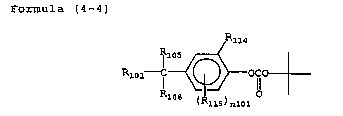
 wherein R101 represents a group which forms an acid having pKa of 5 or less in the form of R101 OH; R102 represents any of 2-alkyl-2-propyl group, 2-aryl-2-propyl group, cyclohexyl group, tetrahydropyranyl group and bis(p-alkoxyphenyl)methyl group; R103, R104, R115 and R117 each independently represent a substituent; R105, R106, R107, R110, R113 and R116 each independently represent a hydrogen atom or substituent; R108 and R109 each represent an alkyl group and may be connected to each other to form a ring; R111 and R112 represent alkyl groups which are connected to each other to form a ring; R114 represents a hydrogen atom or nitro group; and n101 represents an integer of from 0 to 3.
- (A-16) The hologram recording material composition according to Clause (A-15), wherein in the general formulae (4-1) to (4-6), R101 represents any of sulfonic acid and electrophilic group-substituted carboxylic acid in the form of R101OH.
- (A-17) The hologram recording material composition according to anyone of Clauses (A-4) to (A-9), wherein the interference fringe recording component comprises at least a base-induced color-forming dye precursor as a dye precursor and a base generator.
- (A-18) The hologram recording material
composition according to Clause (A-17), wherein the base
generator is represented by any of the following general
formulae (1-1) to (1-4):


 wherein R1, R2, R13, R14 and R15 each independently represent any one of hydrogen atom, alkyl group, alkenyl group, cycloalkyl group, aryl group and heterocyclic group; R1 and R2 may be connected to each other to form a ring; R13, R14 and R15 may be connected to each other to form a ring; R3, R6, R7 and R9 each independently represent a substituent; R4, R5, R8, R10 and R11 each independently represent a hydrogen atom or substituent; R10 and R11 may be connected to each other to form a ring; R16, R17, R18 and R19 each independently represent an alkyl or aryl group; R12 represents an aryl group or heterocyclic group; n1 represents an integer of 0 or 1; and n2 to n4 each independently represent an integer of from 0 to 5.
- (A-19) The hologram recording material composition according to Clause (A-18), wherein in the general formulae (1-1) and (1-2), n1 is 1.
- (A-20) The hologram recording material composition according to Clause (A-18) or (A-19), wherein in the general formula (1-1), R3 represents a 2- or 2,6-substituted nitro group or 3,5-substituted alkoxy group.
- (A-21) The hologram recording material composition according to Clause (A-18) or (A-19), wherein in the general formula (1-2), R6 represents a 3,5-substituted alkoxy group.
- (A-22) The hologram recording material composition according to any one of Clauses (A-17) to (A-21), wherein the base-induced color-forming dye precursor is an undissociated form of dissociative azo dye, dissociative azomethine dye, dissociative oxonol dye, dissociative xanthene (preferably fluorane) dye or dissociative triphenylmethane dye.
- (A-23) The hologram recording material composition according to any one of Clauses (A-17) to (A-22), wherein the interference fringe recording component comprises at least a base-induced color-forming dye precursor as a dye precursor, a base generator and a base proliferator.
- (A-24) The hologram recording material
composition according to Clause (A-23), wherein the base
proliferator is represented by the following general
formula (5):
wherein R121 and R122 each independently represent any one of hydrogen atom, alkyl group, alkenyl group, cycloalkyl group, aryl group and heterocyclic group; R121 and R122 may be connected to each other to form a ring; R123 and R124 each independently represent a substituent; R123 and R124 may be connected to each other to form a ring; R125 and R126 each independently represent a hydrogen atom or substituent; and n102 represents an integer of 0 or 1.

- (A-25) The hologram recording material composition according to Clause (A-24), wherein in the general formula (5), n102 is 1.
- (A-26) The hologram recording material
composition according to Clause (A-24) or (A-25), wherein
the base proliferator of the general formula (5) is
represented by the following general formula (6-1) or
(6-2):
 wherein R121 and R122 are according to the general formula (5).
- (A-27) The hologram recording material
composition according to any one of Clauses (A-4) to (A-9),
wherein the interference fringe recording component
comprises at least a dye precursor represented by the
following general formula (2):
- (A-28) The hologram recording material
composition according to Clause (A-27), wherein the dye
precursor of the general formula (2) is represented by
any of the following general formulae (3-1) to (3-6):


 wherein PD is according to the general formula (2); R71, R80 and R81 each independently represent a hydrogen atom or substituent; R72, R73, R78, R79, R82 and R83 each independently represent a substituent; R74 to R77 each independently represent an alkyl group; a71, a72, a74 and a75 each independently represent an integer of from 0 to 5; a73 and a76 each independently represent 0 or 1; when a71, a72, a74 and a75 are 2 or more, the plurality of R72'S, R73'S, R78'S and R79'S each may be the same or different or may be connected to each other to form a ring; R80 and R81 may be connected to each other to form a ring; and R82 and R83 may be connected to each other to form a ring.
- (A-29) The hologram recording material composition according to Clause (A-27) or (A-28), wherein in the general formula (2) or general formulae (3-1) to (3-6), PD is a group formed by any of dissociative azo dye, dissociative azomethine dye, dissociative oxonol dye, triphenylmethane dye and xanthene dye and covalently bonded to A1 on a chromophore.
- (A-30) The hologram recording material composition according to anyone of Clauses (A-1) to (A-29) , comprising an electron-donating compound capable of reducing radical cations of sensitizing dye or an electron-accepting compound capable of oxidizing radical anions of sensitizing dye.
- (A-31) The hologram recording material composition according to Clause (A-30), wherein there is incorporated an electron-donating compound which is any one of alkylamine, aniline, phenylenediamine, triphenylamine, carbazole, phenothiazine, phenoxazine, phenazine, hydroquinone, catechol, alkoxybenzene, aminophenol, imidazole, pyridine, metalocene, metal complex and particulate semiconductor.
- (A-32) The hologram recording material composition according to Clause (A-31), wherein the electron-donating compound is a phenothiazine.
- (A-33) The hologram recording material composition according to any one of Clauses (A-1) to (A-29), comprising an electron-accepting compound capable of oxidizing radical anions of sensitizing dye.
- (A-34) The hologram recording material composition according to Clause (A-33), wherein there is incorporated an electron-accepting compound which is any one of aromatic compound having an electrophilic group incorporated therein such as dinitrobenzene and dicyanobenzene, heterocyclic compound, heterocyclic compound having an electrophilic group incorporated therein, N-alkylpyridinium salt, benzoquinone, imide, metal complex and particulate semiconductor.
- (A-35) A hologram recording material comprising a hologram recording material composition according to any one of Clauses (A-1) to (A-32).
- (A-36) A non rewritable process hologram recording method comprising a step at which a sensitizing dye is subjected to exposure to absorb light and produce excited state, a chemical reaction step involving color development reaction accompanied by the transfer of electron or energy from the excited state and a hologram formation step involving the chemical reaction.
- (A-37) The hologram recording method according to Clause (A-36), wherein exposure is not followed by any wet processing.
- (A-38) The hologram recording method according to Clause (A-35), wherein volume phase hologram recording is conducted using a hologram recording material according to Clause (A-35).
- (A-39) The hologram recording method according to Clause (A-35) or (A-36), wherein holographic exposure is followed by heat treatment during hologram recording using a hologram recording material according to Clause (A-35).
- (A-40) The hologram recording method according to any one of Clauses (A-36) to (A-39), wherein multi-recording (preferably composed of 50 or more times of recording) is conducted using a hologram recording material according to Clause (A-35).
- (A-41) The hologram recording method according to Clause (A-40), wherein multi-recording composed of 100 or more times of recording is conducted using a hologram recording material according to Clause (A-35).
- (A-42) The hologram recording method according to Clause (A-40) or (A-41), wherein any multi-recording can be effected with exposure kept constant.
- (A-43) An optical recording medium comprising a hologram recording material according to Clause (A-35) and amethod for recording on the optical recording medium.
- (A-44) The optical recording medium according to Clause (A-43), wherein the hologram recording material according to Clause (A-35) is kept in a light-shielding cartridge during storage.
- (A-45) A three-dimensional display hologram comprising a hologram recording material according to any one of Clauses (A-35) to (A-42) and employing a hologram recording method according to any one of Clauses (A-35) to (A-42) and a process for the production of the three-dimensional display hologram.
- (A-46) A holographic optical element comprising a hologram recording material according to any one of Clauses (A-35) to (A-42) and employing a hologram recording method according to any one of Clauses (A-35) to (A-42) and a process for the production of the holographic optical element.
- (B-1) A hologram recording method comprising at least a first step at which holographic exposure is effected to form a latent image and a second step at which the latent image is amplified to form an interference fringe , wherein the two steps are effected in a dry process (The first step corresponds to the hologram recording according to Clause (A-1)).
- (B-2) The hologram recording method according to Clause (B-1), wherein the second step comprises amplifying the latent image to perform refractive index modulation by which an interference fringe is formed.
- (B-3) The hologram recording method according to Clause (B-1) or (B-2) , wherein the second step is triggered by any one of irradiation with light, application of heat and application of electric field.
- (B-4) The hologram recording method according to Clause (B-3), wherein the second step involves any one of irradiation with light, application of heat and application of electric field and a hologram recording material allowing such a recording.
- (B-5) The hologram recording method according to Clause (B-3), wherein the second step involves any of irradiation with light and application of heat.
- (B-6) The hologram recording method according to Clause (B-3), wherein the second step involves irradiation with light.
- (B-7) The hologram recording method according to any one of Clauses (B-1) to (B-7), wherein the first step comprises forming a colored material having no absorption in the wavelength of hologram-reproducing light as a latent image and the second step comprises irradiating the colored material latent image with light having a different wavelength from that of holographic exposure to make self-sensitized amplified production of colored material by which an interference fringe is recorded as refractive index modulation.
- (B-8) The hologram recording method according to any one of Clauses (B-1) to (B-7), wherein no silver halides are used.
- (B-9) The hologram recording method according to any one of Clauses (B-1) to (B-8), wherein hologram recording employs a nonrewritable process.
- (B-10) A hologram recording material allowing
hologram recording by a hologram recording method
according to any one of Clause (B-1) to (B-9), comprising
as a compound group at least:
- 1) a sensitizing dye which absorbs light at holographic exposure of the first step to produce excited state; and
- 2) an interference fringe recording component containing a dye precursor which can form a colored material having absorption in a longer wavelength than the original state and no absorption in the wavelength of hologram-reproducing light and capable of recording an interference fringe using refractive index modulation by color development which occurs via the step of transfer of electron or energy from the excited state of sensitizing dye or colored material.
- (B-11) The hologram recording material according to Clause (B-10), wherein the dye precursor contained in the interference fringe recording component can form a colored material having absorption in a longer wavelength than the original state, no absorption in the wavelength of hologram-reproducing light and an absorption maximum in the range between the wavelength of hologram-reproducing light and the wavelength 200 nm shorter than the wavelength of hologram-reproducing light.
- (B-12) The hologram recording material according to Clause (B-11), wherein the dye precursor contained in the interference fringe recording component can form a colored material having absorption in a longer wavelength than the original state, no absorption in the wavelength of hologram-reproducing light and an absorption maximum in the range between the wavelength of hologram-reproducing light and the wavelength 100 nm shorter than the wavelength of hologram-reproducing light.
- (B-13) The hologram recording method according to any one of Clauses (B-10) to (B-12), comprising a first step at which a hologram recording material according to Clause (B-10) to (B-12) is subjected to holographic exposure to produce excited state of sensitizing dye from which electron or energy moves to an interference fringe recording component to form a colored material having absorption in a longer wavelength than the original state and no absorption in the wavelength of hologram-reproducing light as a latent image and a second step at which the hologram recording material is irradiated with light having a wavelength different from and shorter than that of holographic exposure within which wavelength the molar absorptivity of the sensitizing dye is 5,000 or less to allow the colored material formed as a latent image at the first step to be self-sensitized, causing color development by which refractive index modulation is effected to record an interference fringe, wherein the two steps are effected in a dry process, and a hologram recording material allowing the recording method.
- (B-14) The hologram recording method according to Clause (B-13), wherein the second step comprises irradiating the hologram recording material with light having a wavelength different from and shorter than that of holographic exposure within which wavelength the molar absorptivity of the sensitizing dye is 1,000 or less to allow the colored material formed as a latent image at the first step to be self-sensitized, causing color development by which refractive index modulation is effected to record an interference fringe and a hologram recording material allowing the recording method.
- (B-15) The hologram recording method according to Clause (B-13), wherein the second step comprises irradiating the hologram recording material with light having a wavelength different from and shorter than that of holographic exposure within which wavelength the molar absorptivity of the sensitizing dye is 500 or less to allow the colored material formed as a latent image at the first step to be self-sensitized, causing color development by which refractive index modulation is effected to record an interference fringe and a hologram recording material allowing the recording method.
- (B-16) The hologram recording method according to any one of Clauses (B-10) to (B-15), wherein the second step comprises irradiating the hologram recording material with light having a wavelength different from and shorter than that of holographic exposure within which wavelength the molar absorptivity of the sensitizing dye is 1,000 or more to allow the colored material formed as a latent image at the first step to be self-sensitized, causing color development by which refractive index modulation is effected to record an interference fringe and a hologram recording material allowing the recording method.
- (B-17) The hologram recording material according to any one of Clauses (B-10) to (B-16), wherein the interference fringe recording component comprises at least an acid-induced color-forming dye precursor as a dye precursor and an acid generator.
- (B-18) The hologram recording material according to Clause (B-17), wherein the acid generator is a diaryl iodonium salt, sulfonium salt, diazonium salt, trihalomethyl-substituted triazine or sulfonic acid ester.
- (B-19) The hologram recording material according to Clause (B-18), wherein the acid generator is a diaryl iodonium salt, sulfonium salt or sulfonic acid ester.
- (B-20) The hologram recording material according to any one of Clauses (B-17) to (B-19) , wherein the colored material produced by the acid-induced color-forming dye precursor is a xanthenic (preferably fluorane-based) dye or triphenylmethane dye.
- (B-21) The hologram recording material according to any one of Clauses (B-17) to (B-21), wherein the interference fringe recording component further comprises an acid proliferator.
- (B-22) The hologram recording material according
to Clause (B-21), wherein the acid proliferator is a
compound represented by any one of the following general
formulae (4-1) to (4-6):


 wherein R101 represents a group which forms an acid having pKa of 5 or less in the form of R101 OH; R102 represents any of 2-alkyl-2-propyl group, 2-aryl-2-propyl group, cyclohexyl group, tetrahydropyranyl group and bis(p-alkoxyphenyl)methyl group; R103, R104, R115 and R117 each independently represent a substituent; R105, R106, R107, R110, R113 and R116 each independently represent a hydrogen atom or substituent; R108 and R109 each represent an alkyl group and may be connected to each other to form a ring; R111 and R112 represent alkyl groups which are connected to each other to form a ring; R114 represents a hydrogen atom or nitro group; and n101 represents an integer of from 0 to 3.
- (B-23) The hologram recording material composition according to Clause (B-22), wherein in the general formulae (4-1) to (4-6), R101 represents any of sulfonic acid and electrophilic group-substituted carboxylic acid in the form of R101OH.
- (B-24) The hologram recording material composition according to any one of Clauses (B-10) to (B-16), wherein the interference fringe recording component comprises at least abase-induced color-forming dye precursor as a dye precursor and a base generator.
- (B-25) The hologram recording material
composition according to Clause (B-24), wherein the base
generator is represented by any of the following general
formulae (1-1) to (1-4):


 wherein R1, R2, R13, R14 and R15 each independently represent any one of hydrogen atom, alkyl group, alkenyl group, cycloalkyl group, aryl group and heterocyclic group; R1 and R2 may be connected to each other to form a ring; R13, R14 and R15 may be connected to each other to form a ring; R3, R6, R7 and R9 each independently represent a substituent; R4, R5, R8, R10 and R11 each independently represent a hydrogen atom or substituent; R10 and R11 may be connected to each other to form a ring; R16, R17, R18 and R19 each independently represent an alkyl or aryl group; R12 represents an aryl group or heterocyclic group; n1 represents an integer of 0 or 1; and n2 to n4 each independently represent an integer of from 0 to 5.
- (B-26) The hologram recording material composition according to Clause (B-25), wherein in the general formulae (1-1) and (1-2), n1 is 1.
- (B-27) The hologram recording material composition according to Clause (B-25) or (B-26), wherein in the general formula (1-1), R3 represents a 2- or 2,6-substituted nitro group or 3,5-substituted alkoxy group.
- (B-28) The hologram recording material composition according to Clause (B-25) or (B-26), wherein in the general formula (1-2), R6 represents a 3,5-substituted alkoxy group.
- (B-29) The hologram recording material composition according to any one of Clauses (B-24) to (B-28), wherein the base-induced color-forming dye precursor is an undissociated form of dissociative azo dye, dissociative azomethine dye, dissociative oxonol dye, dissociative xanthene-based (preferably fluorane-based) dye or dissociative triphenylmethane dye.
- (B-30) The hologram recording material composition according to any one of Clauses (B-24) to (B-29), wherein the interference fringe recording component further comprises a base proliferator.
- (B-31) The hologram recording material
composition according to Clause (B-30), wherein the base
proliferates is represented by the following general
formula (5):
wherein R121 and R122 each independently represent any one of hydrogen atom, alkyl group, alkenyl group, cycloalkyl group, aryl group and heterocyclic group; R121 and R122 may be connected to each other to form a ring; R123 and R124 each independently represent a substituent; R123 and R124 may be connected to each other to form a ring; R125 and R126 each independently represent a hydrogen atom or substituent; and n102 represents an integer of 0 or 1.

- (B-32) The hologram recording material composition according to Clause (B-31), wherein in the general formula (5), n102 is 1.
- (B-33) The hologram recording material
composition according to Clause (B-31) or (B-32), wherein
the base proliferator of the general formula (5) is
represented by the following general formula (6-1) or
(6-2):

 wherein R121 and R122 are according to the general formula (5).
- (B-34) The hologram recording material
composition according to any one of Clauses (B-10) to
(B-16), wherein the interference fringe recording
component comprises at least a dye precursor represented
by the following general formula (2):
- (B-35) The hologram recording material
composition according to Clause (B-34), wherein the dye
precursor of the general formula (2) is represented by
any of the following general formulae (3-1) to (3-6):


 wherein PD is according to the general formula (2); R71, R80 and R81 each independently represent a hydrogen atom or substituent; R72, R73, R78, R79, R82 and R83 each independently represent a substituent; R74 to R77 each independently represent an alkyl group; a71, a72, a74 and a75 each independently represent an integer of from 0 to 5; a73 and a76 each independently represent 0 or 1; when a71, a72, a74 and a75 are 2 or more, the plurality of R72's, R73's, R78's and R79's each may be the same or different or may be connected to each other to form a ring; R80 and R81 may be connected to each other to form a ring; and R82 and R83 may be connected to each other to form a ring.
- (B-36) The hologram recording material composition according to Clause (B-34) or (B-35), wherein in the general formula (2) or general formulae (3-1) to (3-6), PD is a group formed by any of dissociative azo dye, dissociative azomethine dye, dissociative oxonol dye, triphenylmethane dye and xanthene dye and covalently bonded to A1 on a chromophore.
- (B-37) The hologram recording material composition according to any one of Clauses (B-1) to (B-36) , comprising an electron-donating compound capable of reducing radical cations of colored material produced by sensitizing dye or dye precursor or an electron-accepting compound capable of oxidizing radical anions of colored material produced by sensitizing dye or dye precursor.
- (B-38) The hologram recording material composition according to Clause (B-37), wherein there is incorporated an electron-donating compound which is any one of alkylamine, aniline, phenylenediamine, triphenylamine, carbazole, phenothiazine, phenoxazine, phenazine, hydroquinone, catechol, alkoxybenzene, aminophenol, imidazole, pyridine, metalocene, metal complex and particulate semiconductor.
- (B-39) The hologram recording material composition according to Clause (B-38), wherein the electron-donating compound is a phenothiazine.
- (B-40) The hologram recording material composition according to Clause (B-37), wherein the electron-accepting compound is any one of aromatic compound having an electrophilic group incorporated therein such as dinitrobenzene and dicyanobenzene, heterocyclic compound, heterocyclic compound having an electrophilic group incorporated therein, N-alkylpyridinium salt, benzoquinone, imide, metal complex and particulate semiconductor.
- (B-41) A volume phase hologram recording method involving volume phase hologram recording using a hologram recording material according to any one of Clauses (B-1) to (B-40) and a volume phase hologram recording material allowing the volume phase type recording.
- (B-42) The hologram recording method according to any one of Clauses (B-1) to (B-41), wherein holographic exposure is followed by heat treatment at the second step or subsequent steps during hologram recording using a hologram recording material according to any one of Clauses (B-1) to (B-41), and a hologram recording material allowing the recording.
- (B-43) The hologram recording method according to any one of Clauses (B-1) to (B-42), wherein 10 or more times of multi-hologram recording jobs are conducted using a hologram recording material according to any one of Clauses (B-1) to (B-42) to form a latent image at a first step which is followed by a second step at which the latent image is used to form an interference fringe , and a hologram recording material allowing the recording.
- (B-44) The hologram recording method according to Clause (B-43) wherein 100 or more times of multi-hologram recording jobs are conducted using a hologram recording material according to Clause (B-43) form a latent image at a first step which is followed by a second step at which the latent image is used to form an interference fringe, and a hologram recording material allowing the recording.
- (B-45) The hologram recording material and hologram recording method according to any one of Clauses (B-1) to (B-44), wherein any multi-recording job can be effected with exposure kept constant during multi-hologram recording at the first step.
- (B-46) An optical recording medium comprising a hologram recording material according to any one of Clauses (B-1) to (B-45) and a method of recording and reproducing on an optical recording medium using a hologram recording and reproducing method according to any one of Clauses (B-1) to (B-45).
- (B-47) An optical recording medium wherein a hologram recording material according to any one of Clauses (B-1) to (B-45) is kept in a light-shielding cartridge during storage.
- (B-48) A three-dimensional display hologram comprising a hologram recording material according to any one of Clauses (B-1) to (B-44) and a process for the production of a three-dimensional display hologram using a hologram recording method according to any one of Clauses (B-1) to (B-44).
- (B-49) A holographic optical element comprising a hologram recording material according to any one of Clauses (B-1) to (B-44) and a process for the production of a holographic optical element using a hologram recording method according to any one of Clauses (B-1) to (B-44).
-
- It was found that the use of the hologram recording material of the invention makes it possible to perform hologram recording with a high sensitivity, a high diffraction efficiency and a linear rise of refractive index modulation relative to exposure. Further, since no shrinkage occurs during recording, the hologram recording material is advantageous in transfer speed, multi-recording properties, etc. during the application to holographic memory, etc.
- It was also found that the use of the holographic exposure latent image-color forming self-sensitized amplification process hologram recording material and method of the invention makes it possible to perform hologram recording with a high sensitivity, a high diffraction efficiency and a linear rise of refractive index modulation relative to exposure. Further, since no shrinkage occurs during recording, the holographic exposure latent image-color forming self-sensitized amplification process hologram recording material and method of the invention are advantageous in transfer speed, multi-recording properties, recording density, etc. during the application to holographic memory, etc.
- The sole figure is a schematic view showing a 2-beam optical system for holographic exposure.
-
- 10
- YAG laser
- 12
- laser beam
- 14
- mirror
- 20
- beam splitter
- 22
- beam segment
- 24
- mirror
- 26
- spatial filter
- 40
- beam expander
- 30
- hologram recording material
- 28
- sample
- 32
- He-Ne laser beam
- 34
- He-Ne laser
- 36
- detector
- 38
- rotating stage
- The hologram recording material composition and hologram recording material of the invention will be further described hereinafter.
- The hologram recording material of the invention and its composition comprises at least one set of compound group allowing hologram recording by a principle other than recording method involving polymerization accompanied by the movement of materials and recording method involving the change of orientation of a birefringent compound.
- The hologram recording material of the invention preferably involves no wet processing after holographic exposure.
- Further, the hologram recording method of the invention preferably employs a nonrewritable process. The term "nonrewritable process" as used herein is meant to indicate a process involving recording by an irreversible reaction allowing the storage of data once recorded without being overwritten (rewritten). Accordingly, the nonrewritable process is suitable for storage of data which are important and needed to be stored over an extended period of time. However, the nonrewritable process allows additional recording of data on unwritten area. In this sense, the nonrewritable process is normally called "write-once-read-many process".
- The compound group allowing hologram recording of the invention preferably contains at least a sensitizing dye which is subjected to holographic exposure to absorb light and produce excited state and an interference fringe recording component which undergoes chemical reaction when electron or energy moves from the excited state of sensitizing dye to record an interference fringe formed by holographic exposure.
- Further, the interference fringe recording component preferably contains a dye precursor which can form a colored material that changes in its absorption from the original state directly or indirectly (e.g., via the generation of an acid or base) when electron or energy moves from the excited state of sensitizing dye.
- In the invention, even if the precursor is colored, the reaction involving the change of its absorption wavelength or absorptivity is called color development reaction and the dye produced by the color development reaction is called colored material. In other words, the color development reaction contains fading reaction.
- The hologram recording method of the invention and the hologram recording material allowing the recording method are characterized in that there comprises at least a first step at which holographic exposure is conducted to form a latent image and a second step at which the latent image is amplified to form an interference fringe , wherein the two steps are effected in a dry process. More preferably, there comprises a second step at which the latent image is amplified to perform refractive index modulation by which an interference fringe is formed.
- The term "latent image" as used in the first step of the invention is meant to indicate an "interference fringe which has been subjected to refractive index modulation in a proportion of preferably half or less of refractive index modulation formed after the second step (that is, a step of amplification of a factor or two or more is effected or a diffraction efficiency rise of twice or more is shown at the second step), more preferably one fifth or less, more preferably one tenth or less of refractive index modulation formed after the second step (that is, a step of amplification of a factor or preferably 5 or more, more preferably 10 or more, even more preferably 30 or more is effected or a diffraction efficiency rise of preferably 5 or more times, more preferably 10 or more times, even more preferably 30 or more times is shown at the second step)".
- The second step is preferably triggered by any one of irradiation with light, application of heat, application of electric field and application of magnetic field. These treatments are preferably made on the entire surface of the recording material.
- The second step preferably involves any one of irradiation with light, application of heat and application of electric field, more preferably either irradiation with light or application of heat, most preferably irradiation with light.
- In the case where the second step involves irradiation with light, the recording material is preferably exposed to light on the entire surface thereof (so-called solid exposure, blanket exposure, non-imagewise exposure).
- Preferred examples of the light source employable herein include visible laser, ultraviolet laser, infrared laser, carbon arc, high voltage mercury vapor lamp, xenon lamp, metal halide lamp, fluorescent lamp, tungsten lamp, LED, and organic EL. In order to emit light having a specific wavelength, a sharp cut filter, abandpass filter, a diffraction grating, etc. are preferably used as necessary.
- The hologram recording material of the invention is preferably free of silver halide.
- The hologram recording method preferably employs a nonrewritable process. The term "nonrewritable process" as used herein is meant to indicate a process involving recording by an irreversible reaction allowing the storage of data once recorded without being overwritten (rewritten). Accordingly, the nonrewritable process is suitable for storage of data which are important and needed to be stored over an extended period of time. However, the nonrewritable process allows additional recording of data on unwritten area. In this sense, the nonrewritable process is normally called "write-once-read-many process".
- The hologram recording method of the invention and the hologram recording material allowing the recording preferably comprise at least a first step at which a colored material having no absorption in the wavelength of hologram-reproducing light is formed as a latent image by holographic exposure and a second step at which the colored material latent image is irradiated with light having a wavelength different from that of holographic exposure to make self-sensitized amplified production of colored material by which an interference fringe is recorded as refractive index modulation, wherein the two steps are effected in a dry process.
- More preferably, the hologram recording material of the invention comprises as a compound group allowing hologram recording at least:
- 1) a sensitizing dye which absorbs light at holographic exposure of the first step to produce excited state; and
- 2) an interference fringe recording component containing a dye precursor which can form a colored material having absorption in a longer wavelength than the original state and no absorption in the wavelength of hologram-reproducing light and capable of recording an interference fringe using refractive index modulation by color development which occurs via the step of transfer of electron or energy from the excited state of sensitizing dye or colored material.
-
- Even more preferably, the hologram recording method and the hologram recording material allowing the recording method comprise a first step at which a hologram recording material according to Clauses (B-10) to (B-12) is subjected to holographic exposure to produce excited state of sensitizing dye from which electron or energy moves to an interference fringe recording component to form a colored material having absorption in a longer wavelength than the original state and no absorption in the wavelength of hologram-reproducing light as a latent image and a second step at which the hologram recording material is irradiated with light having a wavelength different from and shorter than that of holographic exposure within which wavelength the molar absorptivity of the sensitizing dye is 5, 000 or less to allow the colored material formed as a latent image at the first step to be self-sensitized, causing color development by which refractive index modulation is effected to record an interference fringe , wherein the two steps are effected in a dry process.
- The molar absorptivity of the sensitizing dye in the wavelength range of light emitted at the second step is preferably 1, 000 or less, more preferably 500 or less. The molar absorptivity of the colored material in the wavelength range of light emitted at the second step is preferably 1,000 or more.
- The compound group allowing hologram recording of the invention comprises at least:
- 1) a sensitizing dye which absorbs light at holographic exposure of the first step to produce excited state; and
- 2) an interference fringe recording component containing a dye precursor which can form a colored material having absorption in a longer wavelength than the original state and no absorption in the wavelength of hologram-reproducing light and capable of recording an interference fringe using refractive index modulation by color development which occurs via the step of transfer of electron or energy from the excited state of sensitizing dye or colored material.
-
- The hologram recording material of the invention and its composition preferably comprise a binder and optionally additives such as electron-donating compound, electron-accepting compound, polymerizable monomer, polymerizable oligomer, polymerization initiator, crosslinking agent, heat stabilizer, plasticizer and solvent incorporated therein besides the sensitizing dye and interference fringe recording component.
- However, the interference fringe recording method (refractive index modulation) using the hologram recording material of the invention itself does not necessarily require binder, polymerizable monomer, polymerizable oligomer, etc. These additives are used for the purpose of enhancing the film hardenability and storage properties and reducing the percent shrinkage.
- The hologram recording material of the invention is preferably adapted for volume phase hologram recording. As previously mentioned, volume phase hologram recording involves recording of interference fringe s as refractive index modulation by a number as large as 1, 000 to 7,000 per mm along the thickness in the direction parallel to or substantially parallel to the surface of the recording material (reflection type) or perpendicular to or substantially perpendicular to the surface of the recording material (scanning type).
- The hologram recording material of the invention and its composition preferably has different refractive indexes from the interference bright portion which undergoes chemical reaction (preferably color development) when electron or energy moves from the excited state of sensitizing dye or colored material to the interference dark portion which undergoes no chemical reaction when electron or energy moves from the excited state of sensitizing dye or colored material.
- The hologram recording material of the invention is preferably subjected to fixing by either or both of light and heat after holographic exposure.
- In particular, in the case where the hologram recording material of the invention comprises an acid proliferator or base proliferator incorporated therein, fixing is preferably carried out by heating to allow the acid proliferator or base proliferator to perform its function effectively.
- In the case of fixing by light, the hologram recording material is irradiated with ultraviolet rays or visible light on the entire surface thereof (non-interference exposure). Preferred examples of the light source employable herein include visible laser, ultraviolet laser, infrared laser, carbon arc, high voltage mercury vapor lamp, xenon lamp, metal halide lamp, fluorescent lamp, tungsten lamp, LED, and organic EL.
- Heat fixing, if effected, is preferably carried out at a temperature of from 40°C to 160°C, more preferably from 60°C to 130°C.
- In the case where both fixing by light and heat fixing are effected, light and heat may be applied at the same time or separately.
- In the invention, the aforementioned first step and second step may each also involve fixing. Preferably, the second step also involves fixing.
- During the interference fringe recording, refractive index modulation is preferably from 0.00001 to 0.5, more preferably from 0.0001 to 0.3.
- Preferably, the greater the thickness of the hologram recording material is, the less is the refractive index modulation. On the contrary, the smaller the thickness of the hologram recording material is, the more is the refractive index modulation.
- The diffraction efficiency η of the hologram recording material is given by the following equation (1) :
- The light (for recording and reproduction) to be used in the invention is preferably any one of ultraviolet ray, visible light and infrared ray having a wavelength of from 200 to 2,000 nm, more preferably ultraviolet ray or visible light having a wavelength of from 300 to 700 nm, even more preferably visible light having a wavelength of from 400 to 700 nm.
- The light to be used in the invention is preferably coherent (phase and wavelength-adjusted) laser beam. As the laser there may be used any of solid laser, semiconductor laser, gas laser and liquid laser. Preferred examples of laser beam employable herein include frequency-doubled YAG laser beam of 532 nm, frequency-tripled YAG laser beam of 355 nm, GaN laser beam of 405 to 415 nm, Ar ion laser beam of 488 nm or 515 nm, He-Ne laser beam of 632 nm or 633 nm, Kr ion laser of 647 nm, ruby laser beam of 694 nm, and He-Cd laser beam of 636 nm, 634 nm, 538 nm, 534 nm and 442 nm.
- Alternatively, a pulse laser beam on the order of nanoseconds or picoseconds is preferably used.
- In the case where the hologram recording material of the invention is used for optical recording medium, frequency-doubled YAG laser beam of 532 nm or GaN laser beam of 405 nm to 415 nm is preferably used.
- The wavelength of light to be used in hologram reproduction is the same as or longer than that of light to be used in holographic exposure (recording), preferably the same as that of light to be used in holographic exposure.
- The sensitivity of the hologram recording material is normally represented by exposure per unit area (mJ/cm2). The higher this value is, the higher is the sensitivity. However, the point at which exposure is measured to determine sensitivity differs from literature or patent to literature or patent. In some cases, exposure at the start of recording (refractive index modulation) may be measured. In other cases, exposure giving the maximum diffraction efficiency (maximum refractive index modulation) may be measured. In further cases, exposure giving half the maximum diffraction efficiency may be measured. In still further cases, exposure at which the gradient of diffraction efficiency with respect to exposure E is maximum may be measured.
- According to Kugel-Nick's theoretical equation, refractive index modulation An required to give a certain diffraction efficiency is inversely proportional to the thickness d. In other words, the sensitivity required to give a certain diffraction efficiency differs with thickness. The smaller the thickness d is, the smaller is the required refractive index modulation Δn. Accordingly, the sensitivity cannot be unequivocally compared unless the conditions such as thickness are unified.
- In the invention, the sensitivity is defined by "exposure (mJ/cm2) required to give half the maximum diffraction efficiency". The sensitivity of the hologram recording material of the invention is preferably 2 J/cm2 or less, more preferably 1 J/cm2 or less, even more preferably 500 mJ/cm2 or less, most preferably 200 mJ/cm2 or less when the thickness is from about 10 to 200 µm.
- In order to use the hologram recording material of the invention as an optical recording medium in a holographic memory, a spatial light modulation element (SLM) such as DMD and LCD is preferably used to record a large number of two-dimensional digital data (referred to as "signal light"). The recording is preferably carried out by multi-recording to enhance the recording density. Examples of multi-recording method employable herein include angle-multiple recording, phase-multiple recording, wavelength-multiple recording, and shift-multiple recording. Preferred among these multi-recording methods are angle-multiple recording and shift-multiple recording. In order to read the two-dimensional data reproduced, CCD or DMOS is preferably used.
- In the case where the hologram recording material of the invention is used for optical recording medium, it is essential that multi-recording be effected to enhance the volume (recording density). In this case, multi-recording composed of preferably 10 or more times of recording jobs, more preferably 50 or more times of recording jobs, even more preferably 100 or more times of recording jobs is effected. During any recording job of multi-recording, exposure is preferably kept constant to simplify the recording system and enhance S/N ratio.
- The concept of the hologram recording method of the invention will be described below, but it goes without saying that the invention is not limited thereto. The values given below are provided merely for the qualitative explanation and don't necessarily reflect the quantitative values.
- For example, the hologram recording material is irradiated with YAG·SHG laser beam of 532 nm to allow the sensitizing dye to absorb light and produce excited state. By causing electron or energy to move from the excited state of the sensitizing dye to an interference fringe recording component, the dye precursor contained in the interference fringe recording component is partially caused to turn out to be a colored material as a latent image (first step). Subsequently, the hologram recording material is irradiated with light having a wavelength of from 400 to 450 nm to cause the colored material (latent image) to absorb light and undergo self-sensitization by which the colored material is further produced (dye precursor → colored material) (second step). Since a latent image is not produced too much on the interference dark portion at the first step, little or no self-sensitized color development reaction occurs at the second step, resulting in the occurrence of a great refractive index modulation on the interference bright portion and the interference dark portion which can be recorded as an interference fringe For example, the hologram recording material having date recorded thereon is again irradiated with laser beam of 532 nm, data, image and other data thus recorded can be reproduced. Thus, the hologram recording material of the invention can act as a desired optical material.
- The various components of the hologram recording material composition of the invention will be further described hereinafter.
- The compound group allowing the hologram recording method of the invention comprises at least a sensitizing dye which absorbs light at holographic exposure to produce excited state and an interference fringe recording component capable of undergoing chemical reaction when electron or energy moves from the excited state of sensitizing dye to record an interference fringe formed by holographic exposure.
- Among these components, the sensitizing dye which absorbs light in the hologram recording material of the invention to produce excited state or absorbs light at holographic exposure of the first step to produce excited state will be described.
- The sensitizing dye of the invention preferably absorbs any one of ultraviolet ray, visible light and infrared ray in the wavelength range of from 200 to 2, 000 nm, more preferably ultraviolet ray or visible light in the wavelength range of from 300 to 700 nm, even more preferably visible light in the wavelength range of from 400 to 700 nm to produce excited state.
- Preferred examples of the sensitizing dye employable herein include cyanine dyes, squarilium cyanine dyes, styryl dyes, pyrilium dyes, melocyanine dyes, arylidene dyes, oxonol dyes, azlenium dyes, coumarine dyes, ketocoumarine dyes, styrylcoumarine dyes, pyrane dyes, xanthene dyes, thioxanthene dyes, phenothiazine dyes, phenoxazine dyes, phenazine dyes, phthalocyanine dyes, azaporphyrine dyes, porphyrine dyes, condensed aromatic dyes, perylene dyes, azomethine dyes, anthraquinone dyes, metal complex dyes, and metalocene dyes. More desirable among these sensitizing dyes are cyanine dyes, squarilium cyanine dyes, pyrilium dyes, melocyanine dyes, oxonol dyes, coumarine dyes, ketocoumarine dyes, styrylcoumarine dyes, pyrane dyes, xanthene dyes, thioxanthene dyes, condensed aromatic dyes, metal complex dyes, and metalocene dyes. Even more desirable among these sensitizing dyes are cyanine dyes, melocyanine dyes, oxonol dyes, metal complex dyes, and metalocene dyes.
- In addition to these sensitizing dyes, dyes and dyestuffs disclosed in Sinya Ogawara, "Shikiso Handobukku (Handbook of Dyes)", Kodansha, 1986, Shinya Ogawara, "Kinosei Shikiso no Kagaku (Chemistry of Functional Dyes)", CMC, 1981, and Tadasaburo Ikemori, "Tokushu Kino Zairyo (Specially Functional Materials)", CMC, 1986 may be used as sensitizing dye of the invention. The sensitizing dye to be used in the invention is not limited to these examples. Any dye or dyestuff may be used so far as it absorbs light in the visible range. These sensitizing dyes maybe selected such that they are adapted for the wavelength of radiation from the light source depending on the purpose. Two or more sensitizing dyes may be used in combination depending on the purpose.
- Since the hologram recording material needs to be used in the form of thick layer and light needs to be transmitted by the layer, the molar absorptivity of the sensitizing dye at the wavelength of holographic exposure is preferably reduced to maximize the added amount of the sensitizing dye for the purpose of enhancing sensitivity. The molar absorptivity of the sensitizing dye at the wavelength of holographic exposure is preferably from not smaller than 1 to not greater than 10,000, more preferably from not smaller than 1 to not greater than 5, 000, even more preferably from not smaller than 5 to not greater than 2,500, most preferably from not smaller than 10 to not greater than 1,000.
- The transmittance of the hologram recording material at the recording wavelength is preferably from 10% to 99%, more preferably from 20% to 95%, even more preferably from 30% to 90%, particularly from 40% to 85% from the standpoint of diffraction efficiency, sensitivity and recording density. To this end, the molar absorptivity of the sensitizing dye at the recording wavelength and the molarity of the sensitizing dye to be added are preferably adjusted according to the thickness of the hologram recording material.
- λmax of the sensitizing dye is preferably shorter than the wavelength of hologram recording, more preferably between the wavelength of hologram recording and the wavelength 100 nm shorter than the wavelength of hologram recording.
- Further, the molar absorptivity of the sensitizing dye at the recording wavelength is preferably one fifth or less, more preferably one tenth or less of that at λmax. In particular, when the sensitizing dye is an organic dye such as cyanine dye and melocyanine dye, the molar absorptivity of the sensitizing dye at the recording wavelength is more preferably one twentieth or less, even more preferably one fiftieth or less, particularly one hundredth or less of that at λmax.
- Specific examples of the sensitizing dye employable herein will be given below, but the invention is not limited thereto.
- Particularly preferred examples of metal complex dyes include Ru complex dyes. Particularly preferred examples of metalocene dyes include ferrocene dyes.


- The sensitizing dye of the invention may be commercially available or may be synthesized by any known method.
- In the case where hologram recording is effected using frequency-doubled YAG laser beam of 532 nm, the sensitizing dye to be used is particularly preferably a trimethinecyanine dye having a benzoxazole ring, Ru complex dye or ferrocene. In the case hologram recording is effected using GaN laser beam of 405 to 415 nm, the sensitizing dye to be used is particularly preferably a monomethinecyanine dye having a benzoxazole ring, Ru complex dye or ferrocene.
- In the hologram recording material of the invention and its composition, as the compound group allowing hologram recording there is preferably used an interference fringe recording component capable of undergoing chemical reaction when electron or energy moves from the excited state of sensitizing dye to record an interference fringe formed by holographic exposure.
- The interference fringe recording component in the hologram recording material of the invention containing a dye precursor which can form a colored material having absorption in a longer wavelength than the original state and no absorption in the wavelength of hologram-reproducing light and capable of recording an interference fringe using refractive index modulation by color development which occurs via the step of transfer of electron or energy from the excited state of sensitizing dye or colored material will be further described hereinafter.
- It is herein important that refractive index differs from the position where color development reaction occurs (interference bright portion) to the position where no color development reaction occurs (interference dark portion). In general, a dye shows a high refractive index at a longer wavelength than around the wavelength of absorption maximum (λmax) , particularly in the range of from λmax to wavelength 200 nm longer than λmax. Some dyes show a refractive index as high as more than 2, even more than 2.5.
- On the other hand, organic compound which is not a dye, such as binder polymer shows a refractive index of from about 1.4 to 1.6.
- Accordingly, the interference fringe recording component of the invention preferably comprises a dye precursor which can form a colored material that shows different absorption from the original state under the action of an acid or base generated when electron or energy moves directly from the excited state of sensitizing dye or colored material or when electron or energy moves from the excited state of sensitizing dye or colored material to an acid generator or base generator.
- The hologram recording material of the invention is preferably a phase hologram recording material which records an interference fringe by refractive index modulation from the standpoint of enhancement of diffraction efficiency. In other words, it is preferred that the hologram recording material has little or no absorption in the wavelength of reproducing light during hologram reproduction.
- Accordingly, the dye precursor contained in the interference fringe recording component in the hologram recording material of the invention preferably can form a colored material having absorption in a longer wavelength range than the original state under the action of an acid or base generated when electron or energy moves directly from the excited state of sensitizing dye or colored material or when electron or energy moves from the excited state of sensitizing dye or colored material. The colored material produced by reaction after holographic exposure preferably has no absorption in the wavelength of hologram-reproducing light but has absorption in a shorter wavelength range than the wavelength of hologram-reproducing light. The sensitizing dye preferably decomposes during hologram recording or subsequent fixing step to lose its absorption and sensitizing capability.
- As a result, the hologram recording material of the invention can provide a phase hologram recording material capable of recording an interference fringe by refractive index modulation.
- In order to give a high refractive index modulation, the dye precursor contained in the interference fringe recording component preferably has no absorption in the wavelength of hologram-reproducing light but has absorption in the range between the wavelength of hologram-reproducing light and the wavelength 200 nm shorter than the wave length of hologram-reproducing light, more preferably in the range between the wavelength of hologram-reproducing light and the wavelength 100 nm shorter than the wave length of hologram-reproducing light after holographic exposure.
- Since the wavelength of light to be used in holographic exposure (recoding) is more preferably the same as that of light to be used in hologram reproduction as previously mentioned, the colored material preferably has no absorption in the wavelength of hologram-recording light and hologram-reproducing light.
- Preferred examples of combination of interference fringe recording components in the hologram recording material of the invention will be given below.
- A) Combination of at least an acid-induced color-forming dye precursor as a dye precursor and an acid general formula, and optionally an acid proliferator;
- B) Combination of at least a base-induced color-forming dye precursor as a dye precursor and a base generator, and optionally a base proliferator;
- C) Combination of a compound having a covalent bonding of an organic compound moiety capable of severing the covalent bonding when electron or energy moves to excited state of sensitizing dye and an organic compound moiety which forms a colored material when covalently bonded the former organic compound moiety and when released from the former organic compound moiety, and optionally a base.
- D) Combination of capable of changing its absorption form when electron moves to the excited state of sensitizing dye or colored material.
-
- In any case, the mechanism of transfer of energy from the excited state of sensitizing dye or colored material may be either a Foerster type mechanism involving the occurrence of energy transfer from the singlet excited state of sensitizing dye or colored material or a Dexter type mechanism involving the energy transfer from the triplet excited state of sensitizing dye or colored material.
- In this case, in order to cause efficient transfer of energy, it is preferred that the exciting energy of the sensitizing dye or colored material be greater than that of the dye precursor.
- On the other hand, the mechanism of transfer of electron from the excited state of sensitizing dye or colored material may be either a mechanism involving the transfer of electron from the singlet excited state of sensitizing dye or colored material or a mechanism involving the transfer of electron from the triplet excited state of sensitizing dye or colored material.
- The sensitizing dye or colored material in excited state may give electron to the dye precursor, acid generator or base generator or receive electron therefrom. In the case where the sensitizing dye or colored material in excited state gives electron, in order to cause efficient transfer of electron, it is preferred that the energy of the orbit (LUMO) at which excited electron in the excited state of sensitizing dye or colored material exists be higher than that of LUMO orbit of the dye precursor, acid generator or base generator.
- In the case where the sensitizing dye or colored material in excited state receives electron, in order to cause efficient transfer of electron, it is preferred that the energy of the orbit (LUMO) at which excited electron in the excited state of sensitizing dye or colored material exists be lower than that of LUMO orbit of the dye precursor, acid generator or base generator.
- Preferred examples of combination of interference fringe recording components in the hologram recording material of the invention and its composition will be further described hereinafter.
- Firstly, the case where the interference fringe recording component in the hologram recording material of the invention comprises at least an acid-induced color-forming dye precursor as a dye precursor and an acid generator will be described.
- The term "acid generator" as used herein is meant to indicate a compound capable of generator an acid when energy or electron moves from the excited state of sensitizing dye or colored material. The acid generator preferably stays stable in the dark. The acid generator of the invention is preferably a compound capable of generating an acid when electron moves from the excited state of sensitizing dye or colored material.
- Preferred examples of the acid generator of the invention include the following six systems.
- These acid generators may be used in admixture of two or more thereof in an arbitrary proportion as necessary.
- 1) Trihalomethyl-substituted triazine-based acid generator;
- 2) Diazonium salt-based acid generator;
- 3) Diaryliodonium salt-based acid generator;
- 4) Sulfonium salt-based acid generator;
- 5) Metal-arene complex-based acid generator; and
- 6) Sulfonic acid ester-based acid generator
-
- The aforementioned preferred systems will be further described hereinafter.
- In the case where a specific moiety is referred to as "group" herein, it means that the group may or may not be substituted by one or more (as much as possible) substituents unless otherwise specified. For example, the term "alkyl group" is meant to indicate a substituted or unsubstituted alkyl group. Substituents which can substitute the compounds in the invention are arbitrary.
- In the case where a specific moiety is referred to as "ring" herein, it means that the ring may be monocyclic or condensed ring or may or may not be substituted.
- For example, "aryl group" may be a phenyl group, naphthyl group or substituted phenyl group.
- The trihalomethyl-substituted triazine-based acid generator is preferably represented by the following general formula (11):

- In the general formula (11), R21, R22 and R23 each independently represents a halogen atom, preferably a chlorine atom; and R24 and R25 each independently represents a hydrogen atom, -CR21R22R23, or another substituent.
- Preferred examples of the substituent include an alkyl group (preferably with 1 to 20 carbon atoms, such asmethyl, ethyl, n-propyl, isopropyl, n-butyl, n-pentyl, benzyl, 3-sulfopropyl, 4-sulfobutyl, carboxymethyl or 5-carboxypentyl), an alkenyl group (preferably with 2 to 20 carbon atoms, such as vinyl, allyl, 2-butenyl or 1,3-butadienyl), a cycloalkyl group (preferably with 3 to 20 carbon atoms, such as cyclopentyl, or cyclohexyl), an aryl group (preferably with 6 to 20 carbon atoms, such as phenyl, 2-chlorophenyl, 4-methoxyphenyl, 3-methylphenyl, or 1-naphthyl), a heterocyclic group (preferably with 1 to 20 carbon atoms, such as pyridyl, thienyl, furyl, thiazolyl, imidazolyl, pyrazolyl, pyrolidino, piperidino or morpholino), an alkinyl group (preferably with 2 to 20 carbon atoms, such as ethinyl, 2-propinyl, 1,3-butadinyl, or 2-phenylethinyl), a halogen atom (such as F, Cl, Br or I), an amino group (preferably with 0 to 20 carbon atoms, such as amino, dimethylamino, diethylamino, dibutylamino, or anilino), a cyano group, a nitro group, a hydroxyl group, a mercapto group, a carboxyl group, a sulfo group, a phosphoric acid group, an acyl group (preferably with 1 to 20 carbon atoms, such as acetyl, benzoyl, salicyloyl or pivaloyl), an alkoxy group (poreferably with 1 to 20 carbon atoms, such as methoxy, butoxy or cyclohexyloxy), an aryloxy group (preferably with 6 to 26 carbon atoms, such as phenoxy or 1-naphthoxy), an alkylthio group (preferably with 1 to 20 carbon atoms, such as methylthio or ethylthio), an arylthio group (preferably with 6 to 20 carbon atoms, such as phenylthio or 4-chlorophenylthio), an alkylsulfonyl group (preferably with 1 to 20 carbon atoms, such as methanesulfonyl or butanesulfonyl), an arylsulfonyl group (preferably with 6 to 20 carbon atoms, such as benzenesulfonyl or paratoluenesulfonyl), a sulfamoyl group (preferably with 0 to 20 carbon atoms, such as sulfamoyl, N-methylsulfamoyl or N-phenylsulfamoyl), a carbamoyl group (preferably with 1 to 20 carbon atoms, such as carbamoyl, N-methylcarbamoyl, N,N-dimethylcarbamoyl or N-phenylcarbamoyl), an acylamino group (preferably with 1 to 20 carbon atoms, such as acetylamino, or benzoylamino), an imino group (preferablywith2 to 20 carbon atoms, suchasphthalimino) , an acyloxy group (preferably with 1 to 20 carbon atoms, such as acetyloxy or benzoyloxy) , an alkoxycarbonyl group (preferably with 2 to 20 carbon atoms, such as methoxycarbonyl or phenoxycarbonyl), and a carbamoylamino group (preferably with 1 to 20 carbon atoms, such as carbamoylamino, N-methylcarbamoylamino or N-phenylcarbamoylamino), and more preferably an alkyl group, an aryl group, a heterocyclic group, a halogen atom, a cyano group, a carboxyl group, a sulfo group, an alkoxy group, a sulfamoyl group, a carbamoyl group and an alkoxycarbonyl group.
- R24 preferably represents -CR21R22R23, more preferably -CCl3; and R25 preferably represents -CR21R22R23, an alkyl group, an alkenyl group or an aryl group.
- Specific examples of the acid generating agent of trihalomethyl-substituted triazine type include:
- 2-methyl-4,6-bis(trichloromethyl)-1,3,5-triazine,
- 2,4,6-tris(trichloromethyl)-1,3,5-triazine,
- 2-phenyl-4,6-bis(trichloromethyl)-1,3,5-triazine,
- 2-(4'-methoxyphenyl)-4,6-bis(trichloromethyl)-1,3,5-triazine,
- 2-(4'-trifluoromethylphenyl)-4,6-bis(trichloromethyl )-1,3, 5-triazine,
- 2,4-bis(trichloromethyl)-6-(p-methoxyphenylvinyl)-1, 3,5-triazine, and
- 2-(4'-methoxy-1'-naphthyl)-4,6-bis(trichloromethyl)-1,3,5triazine. Also preferred examples include compounds described in BP No. 1388492 and JP-A No. 53-133428.
-
- An acid generating agent of diazonium salt type is preferably represented by a following general formula (12).

- R26 represents an aryl group or a heterocyclic group, preferably an aryl group, and more preferably a phenyl group.
- R27 represents a substituent (preferred examples of which being same as those for R24); and a21 represents an integer from 0 to 5, preferably 0 to 2; in case a21 is 2 or larger, plural R27 may be mutually same or different, or may be mutually bonded to form a ring.
- X21 - represents an anion where HX21 constitutes an acid with a pKa value (in water, 25°C) of 4 or less, preferably 3 or less and more preferably 2 or less, and can preferably be a chloride, a bromide, an iodide, a tetrafluoroborate, a hexafluorophosphate, a hexafluoroarsenate, a hexafluoroantimonate, a perchlorate, a trifluoromethanesulfonate, a 9,10-dimethoxyanthracene-2-sulfonate, a methanesulfonate, a benzenesulfonate, a 9-trifluoromethylbenzenesulfonate, a tosylate or a tetra(pentafluorophenyl)borate.
- Specific examples of the diazonium acid generating agent include X21 - salts of benzenediazonium, 4-methoxydiazonium and 4-methyldiazonium.
- An acid generating agent of diaryliodonium salt type is preferably represented by a following general formula (13).

- In the general formula (13), X21 - has the same meaning as in the general formula (12); R28 and R29 each independently represents a substituent (preferred examples of which being same as those for R24) , preferably an alkyl group, an alkoxy group, a halogen atom, a cyano group or a nitro group.
- a22 and a23 each independently represents an integer from 0 to 5, preferably 0 to 1; in case a22 or a23 is 2 or larger, plural R28 or R29 may be mutually same or different, or may be mutually bonded to form a ring.
- Specific examples of the diaryl iodonium salt acid generating agent include a chloride, a bromide, an iodide, a tetrafluoroborate, a hexafluorophosphate, a hexafluoroarsenate, a hexafluoroantimonate, a perchlorate, a trifluoromethanesulfonate, a 9,10-dimethoxyanthracene-2-sulfonate, a methanesulfonate, a benzenesulfonate, a 4-trifluoromethylbenzenesulfonate, a tosylate, a tetra(pentafluorophenyl)borate, a perfluorobutanesulfonate, and a pentafluorobenzenesulfonate, of diphenyl iodonium, 4,4'-dichlorodiphenyl iodonium, 4,4' -dimethoxydiphenyl iodonium, 4,4'-dimethyldiphenyl iodonium, 4,4'-di-t-butyldiphenyl iodonium, 4,4'-di-t-amyldiphenyl iodonium, 3,3'-dinitrodiphenyl iodonium, phenyl(p-methoxyphenyl) iodonium, phenyl(p-octyloxyphenyl) iodonium, and bis(p-cyanophenyl) iodonium.
- There can also be employed compounds described in Macromolecules, vol. 10, p. 1307 (1977) anddiaryl iodonium salts described in JP-A Nos. 58-29803 and 1-287105 and Japanese Patent Application No. 3-5569.
- An acid generating agent of sulfonium salt type is preferably represented by a following general formula (14).

- In the general formula (14), X21 - has the same meaning as in the general formula (12); R30, R31 and R32 each independently represents an alkyl group, an aryl group or a heterocyclic group (preferred examples of the foregoing being same as those for R24), preferably an alkyl group, a phenacyl group or an aryl group.
- Specific examples of the sulfonium salt acid generating agent include a chloride, a bromide, a tetrafluoroborate, a hexafluorophosphate, a hexafluoroarsenate, a hexafluoroantimonate, a perchlorate, a trifluoromethanesulfonate, a 9,10-dimethoxyanthracene-2-sulfonate, a methanesulfonate, a benzenesulfonate, a 4-trifluoromethylbenzenesulfonate, a tosylate, a tetra(pentafluorophenyl) borate, a perfluorobutanesulfonate, and a pentafluorobenzenesulfonate, of a sulfonium salt such as triphenyl sulfonium, diphenylphenacyl sulfonium, dimethylphenacyl sulfonium, benzyl-4-hydroxyphenylmethyl sulfonium, 4-t-butyltriphenyl sulfonium, tris(4-methylphenyl) sulfonium, tris(4-methoxyphenyl) sulfonium, 4-phenylthiotriphenyl sulfonium, or bis-1-(4-(diphenylsulfonium)phenyl)sulfide.
- In an acid generating agent of metal allene complex type, metal is preferably iron or titanium.
- Specific preferred examples of the metal allene complex acid generating agent include iron allene complexes described in JP-A No. 1-54440, EP Nos. 109851 and 126712 and J. Imag. Sci., 30, p.174 (1986), ironallene organic boron complexes described in Organometallics, 8, p. 2737 (1989), iron allene complex salts described in Prog. Polym Sci., 21, p.7-8(1996) and titanocenes described in JP-A No. 61-151197.
- An acid generating agent of sulfonate ester type is preferably a sulfonate ester, a sulfonate nitrobenzyl ester, and an imidosulfonate.
- Specific examples of the sulfonate ester include benzoin tosylate, and pyrogallol trimesylate; those of the sulfonate nitrobenzyl ester include o-nitrobenzyl tosylate, 2,6-dinitrobenzyl tosylate, 2',6'-dinitrobenzyl-4-nitrobenzenesulfonate, p-nitrobenzyl-9,10-diethoxyanthracene-2-sulfonate and 2-nitrobenzyltrifluoromethylsulfonate; and those of imidosulfonate include N-tosylphthalic acid imide, 9-fluorenylidene aminotosylate and α-cyanobenzylidenetosylamine.
- In addition, there can also be utilized acid generating agents described for example in UV Curing; Science and Technology, p.23-76, edited by S. Peter Pappas, A Technology Marketing Publication, and B Klingert, M. Riediker and A. Roloff, Comments Inorg. Chem., vol.7, No.3, p.109-138(1988).
- Examples of the acid generating agent, in addition to those in the foregoing, include a photoacid generating agent having an o-nitrobenzyl protective group, described in S. Hayase et al., J. Polymer Sci., 25, 753(1987), E. Reichmanis et al., J. Polymer Sci., Polymer Chem. Ed., 23, 1(1985), D.H.R. Barton et al., J. Chem. Soc., 3571(1965), P.M. Collins et al., J. Chem. Soc., Perkin I, 1695(1975), M. Rudinstein et al., Tetrahedron Lett., (17), 1445(1975), J. W. Walker et al. , J. Am. Chem. Soc., 110, 7170(1989), S. C. Busman et al., J. Imaging Technol., 11(4), 191(1985), H. M. Houlihan et al., Macromolecules, 21, 2001 (1988) , P. M. Collins et al., J. Chem Soc., Chem Commun., 532(1972), S. Hayase et al., Macromolecules, 18, 1799(1985), E. Reichmanis et al., J. Electrochem. Soc., Solid State Sci. Technol., 130(6), F. M. Houlihan et al., Macromolecules, 21, 2001 (1988) , EP Nos. 0290, 750, 046,083, 156,535, 271,851, and 0,388,343, USP Nos. 3,901,710, and 4,181,531, JP-A Nos. 60-198538 and 53-133022, a halogenated sulfolane derivative disclosed in JP-A No. 4-338757 (specifically 3,4-dibromosulfolane or 3,4-dichlorosulfolane), a halogen-containing alkylene glycol ether compound such as methylene glycol bis(2,3-dibromopropyl) ether, a halogen-containing ketone such as 1,1,3,3-tetrabromoacetone or hexachloroacetone, and a halogen-containing alcohol such as 2,3-dibromopropanol.
- Also as the acid generating agent in the invention, there can be employed a polymer in which an acid generating group is introduced into a main chain or in a side chain. In case the acid generating agent in the invention is a polymer in which an acid generating group is introduced into a main chain or in a side chain, such polymer may also function as a binder.
- Specific examples of the compound in which an acid generating group or compound is introduced into a main chain or a side chain of a polymer include compounds described in M. E. Woodhouse et al., J. Am. Chem. Soc., 104, 5586(1982), S. P. Pappas et al., J. Imaging Sci., 30(5), 218 (1986), S. Kondo et al., Makromol. Chem., Rapid Commun., 9, 625(1988), J. V. Crivello et al., J. Polymer Sci., Polymer Chem. Ed., 17, 3845 (1979), USP No. 3, 849, 137, GP No. 3,914,407, JP-ANos. 63-26653, 55-164824, 62-69263, 63-146037, 63-163452, 62-153853, 63-146029 and 2000-143796.
- The acid generating agent in the invention is more preferably:
- 3) diaryl iodonium salt acid generating agent;
- 4) sulfonium salt acid generating agent; or
- 6) sulfonate ester acid generating agent.
-
- All these acid generating agents can also function as a cationic polymerization initiator.
- Also,
- 1) trihalomethyl-substituted triazine acid generating agent;
- 2) diazonium salt acid generating agent;
- 3) diaryl iodonium salt acid generating agent;
- 4) sulfonium salt acid generating agent; and
- 5) metal allene complex acid generating agent; can function as a cationic polymerization initiator and a radical polymerization initiator.
-
- It is therefore possible to use a polymerizable monomer, a polymerizable binder, a reactive binder or a crosslinking agent in combination with the hologram recording material of the invention thereby executing a film hardening or the like by a polymerization or a crosslinking simultaneously with hologram recording.
- In the following an acid-induced color forming dye precursor will be explained, in case an interference fringe recording component in the hologram recording material of the invention and in a composition therefor at least includes an acid-induced color forming dye precursor as a dye precursor and an acid generating agent.
- The acid-induced color forming dye precursor in the invention is a dye precursor that can form a color-developed substance of which absorption is changed from an original state, by an acid generated by the acid generating agent. The acid-induced color forming dye precursor in the invention is preferably a compound of which absorption changes to a longer wavelength by the acid, more preferably a compound which develops a color from a colorless state by an acid.
- The acid-induced color forming dye precursor is preferably a compound of triphenylmethane, phthalide (including indolylphthalide, azaphthalide, and triphenylmethane phthalide), phenothiazine, phenoxazine, fluorane, thiofluorane, xanthene, diphenylmethane, chromenopirazole, leucoauramine, methine, azomethine, rhodamine lactam, quinazoline, diazaxanthene, fluoren, or spiropyrane type. Specific examples of such compound are described for example in JP-A No. 2002-156454 and patents cited therein, JP-A Nos. 2000-281920, 11-279328 and 8-240908.
- The acid-induced color forming dye precursor is more preferably a leuco dye having a partial structure of lactone, lactam, oxazine, or spiropyran, for example a compound of phthalide, fluorane, thiofluorane, phthalide, rhodamine lactam or spiropyran type.
- In the interference fringe recording component of the invention, a dye generated from the acid-induced color forming dye precursor is preferably a xanthene dye, a fluorane dye or a triphenylmethane dye.
- In the following, examples of the acid-induced color forming dye precursor preferred for the interference fringe recording component of the invention are shown, but the present invention is not limited to such following specific examples.
- A preferred precursor for a phthalide dye is represented by a following general formula (21).
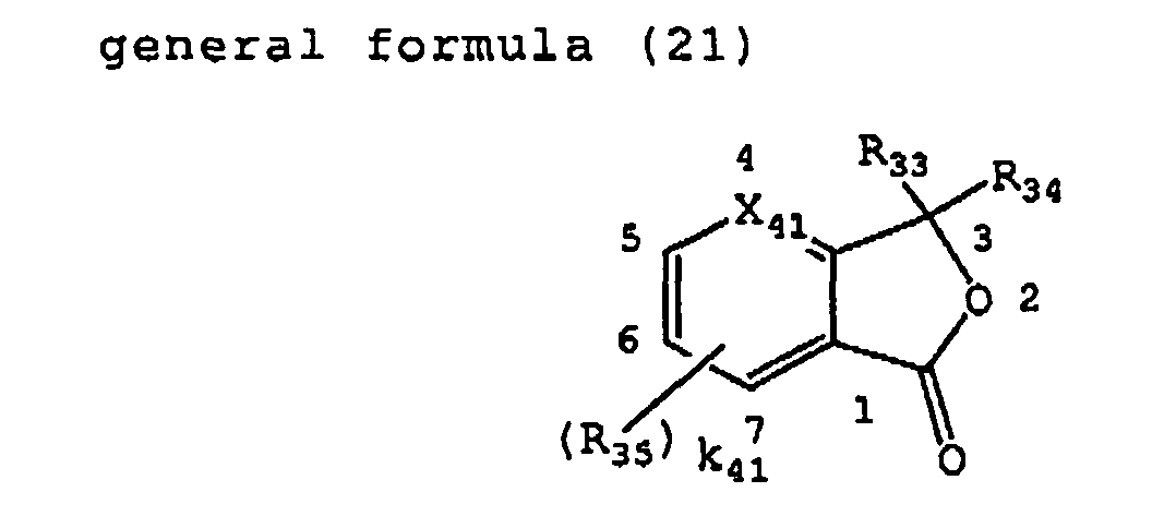
- In the general formula (21), X41 represents CH or N; R33 and R34 each independently represents an alkyl group with 1 to 20 carbon atoms, an aryl group with 6 to 24 carbon atoms, a heterocyclic group with 1 to 24 carbon atoms or a group represented by a following general formula (22) ; and R35 represents a substituent (of which examples being same as those for R24), R35 being more preferably a halogen atom such as a chlorine atom or a bromine atom, an alkyl group with 1 to 20 carbon atoms, an alkoxy group with 1 to 20 carbon atoms, an amino group, an alkylamino group having an alkyl group with 1 to 20 carbon atoms, a dialkylamino group having alkyl groups independently having 1 to 20 carbon atoms, an arylamino group having an aryl group with 6 to 24 carbon atoms, a diarylamino group having aryl groups independently having 6 to 24 carbon atoms, a hydroxyl group, an alkoxy group with 1 to 20 carbon atoms, or a heterocyclic group; and k41 represents an integer of 0 to 4, and, in case k41 is an integer of 2 or larger, plural R35 each independently represents one of groups mentioned above. These groups may further have a substituent, of which preferred examples can be those cited for R24.
- In the general formula (21), each of R33 and R34 is preferably represented by a following general formula (22).

- In the general formula (22), R36 represents an alkylene group with 1 to 3 carbon atoms; k42 represents an integer of 0 to 1; R37 represents a substituent (of which preferred examples are same as those for R24) , R37 being more preferably a halogen atom such as a chlorine atom or a bromine atom, an alkyl group with 1 to 20 carbon atoms, an alkoxy group with 1 to 20 carbon atoms, an amino group, an alkylamino group having an alkyl group with 1 to 20 carbon atoms, a dialkylamino group having alkyl groups independently having 1 to 20 carbon atoms, an arylamino group having an aryl group with 6 to 24 carbon atoms, a diarylamino group having aryl groups independently having 6 to 24 carbon atoms, a hydroxyl group, an alkoxy group with 1 to 20 carbon atoms, or a heterocyclic group; and k43 represents an integer of 0 to 5, and, in case k43 is an integer of 2 or larger, plural R37 each independently represents one of groups mentioned above. These groups may further have a substituent, of which preferred examples can be those cited for R24.
- In the general formula (21), the heterocyclic group represented by R33, R34 is more preferably an indolyl group represented by a following general formula (23).

- In the general formula (23), R38 represents a substituent (of which preferred examples are same as those for R24), R38 being more preferably a halogen atom such as a chlorine atom or a bromine atom, an alkyl group with 1 to 20 carbon atoms, an alkoxy group with 1 to 20 carbon atoms, an amino group, an alkylamino group having an alkyl group with 1 to 20 carbon atoms, a dialkylamino group having alkyl groups independently having 1 to 20 carbon atoms, an arylamino group having an aryl group with 6 to 24 carbon atoms, a diarylamino group having aryl groups independently having 6 to 24 carbon atoms, a hydroxyl group, an alkoxy group with 1 to 20 carbon atoms, or a heterocyclic group; and k44 represents an integer of 0 to 4, and, in case k44 is an integer of 2 or larger, plural R38 each independently represents one of groups mentioned above; R39 represents a hydrogen atom or an alkyl group with 1 to 20 carbon atoms; and R40 represents an alkyl group with 1 to 20 carbon atoms or an alkoxy group with 1 to 20 carbon atoms. These groups may further have a substituent, of which preferred examples can be those cited for R24.
- Specific examples of the phthalide dye precursor (including indophthalide dye precursor and azaphthalide dye precursor) include 3,3-bis(4-diethylaminophenyl)-6-diethylamino phthalide, 3-(4-diethylaminophenyl)-3-(1-ethyl-2-methylindol-3-yl) phthalide, 3-(4-dimethylaminophenyl)-3-(1,3-dimethylindol-3-yl) phthalide, 3,3-bis(1-n-butyl-2-methylindol-3-yl) phthalide, 3,3-bis(1-ethyl-2-methylindol-3-yl) phthalide, 3-(4-diethylamino-2-ethoxyphenyl)-3-(1-ethyl-2-methylindol-3-yl)-4-azaphthalide, 3,3-bis (4-hydroxyphenyl)-6-hydroxy phthalide, 3,3-bis (4-hexyloxyphenyl) phthalide, and 3,3-bis(4-hexyloxyphenyl)-6-methoxyphthalide.
- The phthalide dye precursor represented by the general formula (21) is more preferably a triphenylmethane phthalide dye precursor represented by represented by a following general formula (24).

- In the general formula (24), R41, R42 and R43 each independently represents a substituent (of which preferred examples are same as those for R24), such substituent of R41, R42 and R43 being more preferably a halogen atom such as a chlorine atom or a bromine atom, an alkyl group with 1 to 20 carbon atoms, an alkoxy group with 1 to 20 carbon atoms, an amino group, an alkylamino group having an alkyl group with 1 to 20 carbon atoms, a dialkylamino group having alkyl groups independently having 1 to 20 carbon atoms, an arylamino group having an aryl group with 6 to 24 carbon atoms, a diarylamino group having aryl groups independently having 6 to 24 carbon atoms, a hydroxyl group, an alkoxy group with 1 to 20 carbon atoms, or a heterocyclic group; and k45, k46 and k47 each independently represents an integer of 0 to 4, and, in case each of k45, k46 and k47 is an integer of 2 or larger, plural R41, R42 or R43 each independently represents one of groups mentioned above. These groups may further have a substituent, of which preferred examples can be those cited for R24.
- Specific examples of the triphenylmethane phthalide dye precursor include 3,3-bis(p-dimethylaminophenyl)-6-dimethylaminophthalide (namely crystal violet lactone), 3,3-bis(p-dimethylaminophenyl) phthalide, 3,3-bis(p-dihexylaminophenyl)-6-dimethylamino phthalide, 3,3-bis(p-dioctylaminophenyl) phthalide, 3,3-bis(p-dimethylaminophenyl)-6-diethylaminophthalide, 4-hydroxy-4'-dimethylaminotriphenylmethane lactone, 4,4'-bisdihydroxy-3,3'-bisdiaminotriphenylmethane lactone, 3,3-bis(4-hydroxyphenyl)-4-hydroxyphthalide, 3,3-bis(4-hexyloxyphenyl) phthalide, and 3,3-bis(4-hexyloxyphenyl)-6-methoxyphthalide.
- The fluorane dye precursor is preferably represented by a following general formula (25).

- In the general formula (25) , R44, R45, and R46 each independently represents a substituent (of which preferred examples are same as those for R24), such substituent of R44, R45, and R46 being more preferably a halogen atom such as a chlorine atom or a bromine atom, an alkyl group with 1 to 20 carbon atoms, an alkoxy group with 1 to 20 carbon atoms, an amino group, an alkylamino group having an alkyl group with 1 to 20 carbon atoms, a dialkylamino group having alkyl groups independently having 1 to 20 carbon atoms, an arylamino group having an aryl group with 6 to 24 carbon atoms, a diarylamino group having aryl groups independently having 6 to 14 carbon atoms, a hydroxyl group, or a heterocyclic group; and k48, k49 and k50 each independently represents an integer of 0 to 4, and, in case each of k48, k49 and k50 is an integer of 2 or larger, plural R44, R45 or R46 each independently represents one of groups mentioned above. These groups may further have a substituent, of which preferred examples can be those cited for R24.
- Specific examples of the fluorane dye precursor include 3-diethylamino-6-(2-chloroanilino)fluorane, 3-dibutylamino-6-(2-chloroanilino)fluorane, 3-diethylamino-7-methyl-6-anilinofluorane, 3-dibutylamino)-7-methyl-6-anilinofluorane, 3-dipentylamino-7-methyl-6-anilinofluorane, 3-(N-ethyl-N-isopentylamino)-7-methyl-6-anilinofluorane, 3-diethylamino-7-methyl-6-xylidinofluorane, 3-diethylamino-6,7-benzofluorane, 3-diethylamino-7-methoxy-6,7-benzofluorane, 1,3-dimethyl-6,diethylaminofluorane, 2-bromo-3-methyl-6-dibutylaminofluorane, 2-N,N-dibenzylamino-6-diethylaminofluorane, 3-dimethylamino-6-methoxyfluorane, 3-diethylamino-7-methyl-6-chlorofluorane, 3-diethylamino-6-methoxyfluorane, 3,6-bisdiethylaminofluorane, 3,6-dihexyloxyfluorane, 3,6-dichlorofluorane, and 3,6-diacetyloxyfluorane.
- Specific examples of the rhodamine lactam dye precursor include rhodamine-B-anilinolactam, rhogamine(p-nitroanilino)lactam, rhodamine-B-(p-chloroanilino)lactam and rhodamine-B-(o-chloroanilino)lactam.
- Specific examples of the spiropyran dye precursor include 3-methyl-spirodinaphthopyran, 3-ethyl-spirodinaphthopyran, 3,3'-dichloro-spirodinaphthopyran, 3-benzyl-spirodinaphthopyran, 3-propyl-spirodibenzopyran, 3-phenyl-8'-methoxybenzoindolinospiropyran, 8'-methoxybenzoindolinospiropyran, and 4,7,8'-trimethoxybenzoindolinospiropyran.
- Specific examples also include spiropyran dye precursors disclosed in JP-A No. 2000-281920.
- Furthermore, as the acid-induced color forming dye precursor of the invention, there can be advantageously employed a BLD compound represented by a general formula (6) in JP-A No. 2000-284475, a leuco dye disclosed in JP-A No. 2000-144004 and leuco dyes of following structures.


- In particular, R-2 and R-3 are preferable as the acid-induced color forming dye precursor of the invention.
- Also the dye precursor of the invention may be a leuco cyanine dye which forms a color by an acid (proton) addition. An example of color formation of a leuco cyanine dye by forming a cyanine dye with an acid is shown in the following.

- Preferred examples of the leuco cyanine dye in the invention are shown in the following, but the present invention is not limited to those examples.

- In case the interference fringe recording component of the invention includes at least an acid-induced color forming dye precursor as a dye precursor and an acid generating agent, it may further contain an acid proliferating agent.
- An acid proliferating agent of the invention is a compound that is stable in the absence of an acid but is decomposed in the presence of an acid thereby releasing an acid, which decomposes another acid proliferating agent to further release an acid, thus capable of an acid proliferation utilizing a small amount of acid generated by the acid generating agent as a trigger.
- The acid proliferating agent is preferably represented by the foregoing general formulas (4-1) to (4-6).
- In the general formulas (4-1) to (4-6), R101 represents a group for which R101OH forms an acid with a pKa value of 5 or less, preferably 3 or less.
- R101 is preferably a group for which R101OH is a sulfonic acid, a carboxylic acid, a phosphonic acid, or a phosphinic acid, more preferably it is a sulfonic acid or a carboxylic acid substituted with an electron attracting group, and such electron attracting group is preferably a halogen atom, a cyano group, a nitro group, an alkoxycarbonyl group, a carbamoyl group, an alkylsulfonyl group, an arylsulfonyl group or a heterocyclic group. Most preferably R101 is a group for which R101 OH is a sulfonic acid.
- Specific preferred examples of R101 are shown in the following, but the present invention is not limited to such examples.


- In the general formula (4-1), R102 represents a 2-alkyl-2-propyl group, a 2-aryl-2-propyl group, a cyclohexyl group, a tetrahydropyranyl group, or a bis(p-alkoxyphenyl)methyl group, preferably a 2-alkyl-2-propyl group or a 2-aryl-2-propyl group, more preferably a 2-alkyl-2-propyl group, and most preferably a t-butyl group.
- In the general formula (4-1), R103 and R104 each independently represents a substituent (of which preferred examples are same as those for R24), more preferably each independently represents an alkyl group, an alkenyl group, a cycloalkyl group, an aryl group or a heterocyclic group, further preferably an alkyl group or an aryl group and most preferably an alkyl group.
- In the general formulas (4-1) to (4-6), R105, R106, R107, R110, R113 and R116 each independently represents a hydrogen atom or a substituent (of which preferred examples are same as those for R24), more preferably a hydrogen atom, an alkyl group, an alkenyl group, a cycloalkyl group, an aryl group or a heterocyclic group, further preferably a hydrogen atom, an alkyl group or an aryl group.
- More preferably R105, R106 and R116 are all hydrogen atoms. More preferably R107, R110 and R113 are all alkyl groups.
- In the general formula (4-2), R108 and R109 each independently represents an alkyl group, preferably a methyl group or an ethyl group, or they may be mutually bonded to form a ring, and a ring to be formed is preferably a dioxal ring or a dioxane ring.
- In the general formula (4-3), R111 and R112 represent alkyl groups which are mutually bonded to form a ring, and a ring to be formed is preferably a saturated cycloalkane ring.
- In the general formula (4-4), R114 represents a hydrogen atom or a nitro group, preferably a nitro group; R115 represents a substituent; n101 represents an integer of 0 to 3, preferably 0 or 1 and more preferably 0.
- In the general formula (4-6), R117 represents a substituent (of which preferred examples are same as those for R24), more preferably an alkyl group, an alkenyl group, a cycloalkyl group, an aryl group or a heterocyclic group, further preferably an alkyl group or an aryl group and most preferably an alkyl group.
- The acid proliferating agent of the invention is more preferably represented by any of the general formulas (4-1), (4-3) or (4-4), and most preferably by the general formula (4-1).
- Specific examples of the acid proliferating agent of the invention are shown in the following, but the present invention is not limited to such examples.


- Since heating is preferable for acid proliferation, a heat treatment is preferably executed after a holographic exposure.
- In the following, there will be explained a case where the interference fringe recording component of the invention or a composition therefor includes at least a base-induced color forming dye precursor as a dye precursor and a base generating agent.
- A base generating agent means a compound capable of generating a base by an energy transfer or an electron transfer from a sensitizing dye or an excited state of a color developed substance. The base generating agent is preferably stable in a darkplace. The base generating agent in the invention is preferably a compound capable of generating a base by an energy transfer or an electron transfer from an excited state of a sensitizing dye or a color developed substance.
- The base generating agent of the invention preferably generates a Bronsted's base by light, more preferably an organic base and particularly preferably an amine as an organic base.
- The base generating agent of the invention is preferably represented by the aforementioned general formulas (1-1) to (1-4). These base generating agents may be employed if necessary in a mixture of two or more kinds of an arbitrary ratio.
- In the general formula (1-1) or (1-2), R1 and R2 each independently represents a hydrogen atom, an alkyl group (preferably with 1 to 20 carbon atoms, such as methyl, ethyl, n-propyl, isopropyl, n-butyl, n-pentyl, n-octadecyl, benzyl, 3-sulfopropyl, 4-sulfobutyl, carboxymethyl or 5-carboxypentyl), an alkenyl group (preferably with 2 to 20 carbon atoms, such as vinyl, allyl, 2-butenyl or 1,3-butadienyl), a cycloalkyl group (preferably with 3 to 20 carbon atoms, such as cyclopentyl, or cyclohexyl), an aryl group (preferably with 6 to 20 carbon atoms, such as phenyl, 2-chlorophenyl, 4-methoxyphenyl, 3-methylphenyl, 1-naphthyl or 2-naphthyl), or a heterocyclic group (preferably with 1 to 20 carbon atoms, such as pyridyl, thienyl, furyl, thiazolyl, imidazolyl, pyrazolyl, pyrolidino, piperidino or morpholino), more preferably a hydrogen atom, an alkyl group or a cycloalkyl group, and further preferably ahydrogen atom, amethyl group, an ethyl group, a cyclohexyl group or a cyclopentyl group.
- R1 and R2 may be mutually bonded to form a ring, and a heterocycle to be formed is preferably a piperidine ring, a pyrrolidine ring, a piperadine ring, a morpholine ring, a pyridine ring, a quinoline ring or an imidazole ring, more preferably a piperidine ring, a pyrrolidine ring or an imidazole ring, andmost preferably a piperidine ring.
- A more preferred combination of R1 and R2 includes a case where R1 is a cyclohexyl group that may be substituted and R2 is a hydrogen atom, a case where R1 is an alkyl group that may be substituted and R2 is a hydrogen atom, and a case where R1 and R2 are bonded to form a piperidine ring or an imidazole ring.
- In the general formula (1-1) or (1-2), n1 represents 0 or 1, preferably 1.
- In the general formula (1-1), R3 represents a substituent, and preferred examples of the substituent include an alkyl group (preferably with 1 to 20 carbon atoms, such as methyl, ethyl, n-propyl, isopropyl, n-butyl, n-pentyl, benzyl, 3-sulfopropyl, 4-sulfobutyl, carboxymethyl or 5-carboxypentyl), an alkenyl group (preferably with 2 to 20 carbon atoms, such as vinyl, allyl, 2-butenyl or 1, 3-butadienyl) , a cycloalkyl group (preferably with 3 to 20 carbon atoms, such as cyclopentyl, or cyclohexyl), an aryl group (preferably with 6 to 20 carbon atoms, such as phenyl, 2-chlorophenyl, 4-methoxyphenyl, 3-methylphenyl, or 1-naphthyl), a heterocyclic group (preferably with 1 to 20 carbon atoms, such as pyridyl, thienyl, furyl, thiazolyl, imidazolyl, pyrazolyl, pyrolidino, piperidino or morpholino), an alkinyl group (preferably with 2 to 20 carbon atoms, such as ethinyl, 2-propinyl, 1,3-butadinyl, or 2-phenylethinyl), a halogen atom (such as F, Cl, Br or I), an amino group (preferably with 0 to 20 carbon atoms, such as amino, dimethylamino, diethylamino, dibutylamino, or anilino), a cyano group, a nitro group, a hydroxyl group, a mercapto group, a carboxyl group, a sulfo group, a phosphoric acid group, an acyl group (preferably with 1 to 20 carbon atoms, such as acetyl, benzoyl, salicyloyl or pivaloyl), an alkoxy group (poreferably with 1 to 20 carbon atoms, such as methoxy, butoxy or cyclohexyloxy) , an aryloxy group (preferably with 6 to 26 carbon atoms, such as phenoxy or 1-naphthoxy), an alkylthio group (preferably with 1 to 20 carbon atoms, such as methylthio or ethylthio), an arylthio group (preferably with 6 to 20 carbon atoms, such as phenylthio or 4-chlorophenylthio), an alkylsulfonylgroup (preferably with 1 to 20 carbon atoms, such as methanesulfonyl or butanesulfonyl), an arylsulfonyl group (preferably with 6 to 20 carbon atoms, such as benzenesulfonyl or paratoluenesulfonyl), asulfamoylgroup (preferably with 0 to 20 carbon atoms, such as sulfamoyl, N-methylsulfamoyl or N-phenylsulfamoyl), a carbamoyl group (preferably with 1 to 20 carbon atoms, such as carbamoyl, N-methylcarbamoyl, N,N-dimethylcarbamoyl or N-phenylcarbamoyl), an acylamino group (preferably with 1 to 20 carbon atoms, such as acetylamino, or benzoylamino), an imino group (preferablywith 2 to 20 carbon atoms, such as phthalimino) , an acyloxy group (preferably with 1 to 20 carbon atoms, such as acetyloxy or benzoyloxy) , an alkoxycarbonyl group (preferably with 2 to 20 carbon atoms, such as methoxycarbonyl or phenoxycarbonyl), and a carbamoylamino group (preferably with 1 to 20 carbon atoms, such as carbamoylamino, N-methylcarbamoylamino or N-phenylcarbamoylamino), and more preferably an alkyl group, an aryl group, a heterocyclic group, a halogen atom, an amino group, a cyano group, a nitro group, a carboxyl group, a sulfo group, an alkoxy group, an alkylthio group, an arylsulfonyl group, a sulfamoyl group, a carbamoyl group and an alkoxycarbonyl group.
- In the general formula (1-1), R3 is preferably a nitro group or an alkoxy group, more preferably a nitro group or a methoxy group, and most preferably a nitro group.
- In the general formula (1-1), n2 represents an integer of 0 to 5, preferably 0 to 3 and further preferably 1 or 2. In case n2 is 2 or larger, plural R3 may be mutually same or different or may be bonded to form a ring, and a ring to be formed is preferably a benzene ring or a naphthalene ring.
- In case R3 is a nitro group in the general formula (1-1), it is preferably substituted in 2-position or in 2- and 6-positions, and, in case R3 is an alkoxy group, it is preferably substituted in 3- and 5-positions.
- In the general formula (1-1), R4 and R5 each independently represents a hydrogen atom or a substituent (of which preferred examples are same as those for R3), preferably a hydrogen atom, an alkyl group or an aryl group, and more preferably a hydrogen atom, a methyl group or a 2-nitrophenyl group.
- More preferred combination of R4 and R5 includes a case where R4 and R5 are both hydrogen atoms, a case where R4 is a methyl group and R5 is a hydrogen atom, a case where R4 and R5 are both methyl groups, and a case where R4 is a 2-nitrophenyl group and R5 is a hydrogen atom, more preferably a case where R4 and R5 are both hydrogen atoms.
- In the general formula (1-2), R6 and R7 each independently represents a substituent (of which preferred examples are same as those for R3), preferably an alkoxy group, an alkylthio group, a nitro group or an alkyl group, more preferably a methoxy group.
- In the general formula (1-2), n3 and n4 each independently represents an integer of 0 to 5, preferably 0 to 2. In case n3 or n4 is 2 or larger, plural R6 or R7 may be mutually same or different, or may be bonded to form a ring, and a ring to be formed is preferably a benzene ring or a naphthalene ring.
- In the general formula (1-2), R6 is more preferably an alkoxy group substituted in 3- and 5-positions, and further preferably a methoxy group substituted in 3- and 5-positions.
- In the general formula (1-2), R8 represents a hydrogen atom or a substituent (of which preferred examples are same as those for R3), preferably a hydrogen atom or an aryl group, more preferably a hydrogen atom.
- In the general formula (1-3), R9 represents a substituent (of which preferred examples are same as those for R3), preferably an alkyl group, an aryl group, a benzyl group, or an amino group, more preferably an alkyl group that may be substituted, a t-butyl group, a phenyl group, a benzyl group, an aniline group that may be substituted, or a cyclohexylamino group.
- A compound represented by the general formula (1-3) may be a compound connected to a polymer chain from R9.
- In the general formula (1-3), R10 and R11 each independently represents a hydrogen atom or a substituent (of which preferred examples are same as those for R3), preferably an alkyl group or an aryl group, more preferably a methyl group, a phenyl group or a 2-naphthyl group.
- R10 and R11 may be mutually bonded to form a ring, and a ring to be formed is preferably a fluorene ring.
- In the general formula (1-4), R12 represents an aryl group or a heterocyclic group, more preferably an aryl group or a heterocyclic ring shown below.

- In the general formula (1-4), R13, R14 and R15 each independently represents a hydrogen atom, an alkyl group, an alkenyl group, a cycloalkyl group, an aryl group, or a heterocyclic group (preferred examples of the foregoing being same as those for R1 and R2), preferably an alkyl group and more preferably a butyl group. R13, R14 and R15 may be mutually bonded to form a ring, and a heterocycle to be formed is preferably a piperidine ring, apyrrolidine ring, a piperadine ring, a morpholine ring, a pyridine ring, a quinoline ring or an imidazole ring, more preferably a piperidine ring, a pyrrolidine ring or an imidazole ring.
- In the general formula (1-4), R16, R17, R18 and R19 each independently represents an alkyl group or an aryl group, and more preferred is a case where R16, R17 and R18 are all phenyl groups and R19 is an n-butyl group or a phenyl group.
- The base generating agent of the invention is preferably represented by the aforementioned general formula (1-1) or (1-3), more preferably by the general formula (1-1).
- Specific preferred examples of the base generating agent of the invention are shown in the following, but the present invention is not limited to such examples.


- In the following, there will be explained a base-induced color forming dye precursor to be employed in a case where the interference fringe recording component of the invention or a composition therefor includes at least a base-induced color forming dye precursor as a dye precursor and a base generating agent.
- The base-induced color forming dye precursor in the invention is a dye precursor that can form a color-developed substance of which absorption is changed from an original state, by a base generated by the base generating agent. The base-induced color forming dye precursor in the invention is preferably a compound of which absorption changes to a longer wavelength by the acid, more preferably a compound which develops a color from a colorless state by a base.
- The base-induced color forming dye precursor is preferably a non-dissociated substance of a dissociable dye. A dissociable dye means a compound which has, on a dye chromophore, a dissociable group dissociating at a pKa value of 12 or less, preferably 10 or less, to release a proton, and which shows a shift of the absorption to a longer wavelength or a shift from a colorless state to a colored state by the transition from the non-dissociated state to the dissociated state. The dissociable group ca preferably be OH, SH, COOH, PO3H2, SO3H, NR91R92H+, NHSO2R93, CHR94R95 or NHR96.
- R91, R92 and R96 each independently represents a hydrogen atom, an alkyl group, an alkenyl group, a cycloalkyl group, an aryl group or a heterocyclic group (preferred examples of the foregoing being same as those for R3), preferably a hydrogen atom or an alkyl group. R93 represents an alkyl group, an alkenyl group, a cycloalkyl group, an aryl group or a heterocyclic group (preferred examples of the foregoing being same as those for R3), preferably an alkyl group that may be substituted, or an aryl group that may be substituted, more preferably an alkyl group that may be substituted, and a substituent in such case is preferably an electron attracting group, more preferably a fluorine atom.
- R94 and R95 each independently represents a substituent (of which preferred examples are same as those for R3), preferably an electron attracting substituent and more preferably a cyano group, an alkoxycarbonyl group, a carbamoyl group, an acyl group, an alkylsulfonyl group or an arylsulfonyl group.
- The dissociable group of the dissociable dye in the invention is more preferably an OH group, a COOH group, an NHSO2R93 group, an NHR96 group or a CHR94R95 group, further preferably an OH group or a CHR94R95 group, and most preferably an OH group.
- A non-dissociated substance of the dissociable dye preferred as the base-induced color forming dye precursor of the invention can be a non-dissociated substance of a dissociable azo dye, a dissociable azomethine dye, a dissociable oxonol dye, a dissociable arylidene dye, a dissociable xanthene dye, a dissociable fluorane dye or a dissociable triphenylamine dye, more preferably a non-dissociated substance of a dissociable azo dye, a dissociable azomethine dye, a dissociable oxonol dye, or a dissociable arylidene dye.
- In the following, examples of the non-dissociated substance of the dissociable dye are shown as examples of the base-induced color forming dye precursor of the invention, but the present invention is not limited to such examples.


- In case the interference fringe recording component of the invention includes at least a base-induced color forming dye precursor as a dye precursor and a base generating agent, it may further contain a base proliferating agent.
- A base proliferating agent of the invention is a compound that is stable in the absence of a base but is decomposed in the presence of a base thereby releasing a base, which decomposes another base proliferating agent to further release a base, thus capable of a base proliferation utilizing a small amount of base generated by the base generating agent as a trigger.
- The base proliferating agent is preferably represented by the foregoing general formula (5).
- In the general formula (5), R121 and R122 each independently represents a hydrogen atom, an alkyl group, an alkenyl group, a cycloalkyl group, an aryl group, or a heterocyclic group (preferred examples of the foregoing substituent being same as those for R1), more preferably a hydrogen atom, an alkyl group or a cycloalkyl group, and further preferably a hydrogen atom, a methyl group, an ethyl group, a cyclohexyl group or a cyclopentyl group.
- R121 and R122 may be mutually bonded to form a ring, and a heterocycle to be formed is preferably a piperidine ring, a pyrrolidine ring, a piperadine ring, a morpholine ring, a pyridine ring, a quinoline ring or an imidazole ring, more preferably a piperidine ring, a pyrrolidine ring or an imidazole ring, and most preferably a piperidine ring.
- A more preferred combination of R121 and R122 includes a case where R121 is a cyclohexyl group which may be substituted and R122 is a hydrogen atom, a case where R121 is an alkyl group which may be substituted and R122 is a hydrogen atom, and a case where R121 and R122 are mutually bonded to form a piperidine ring or an imidazole ring.
- R123 and R124 each independently represents a hydrogen atom or a substituent (of which preferred examples are same as those for R3), preferably a hydrogen atom, an aryl group or an arylsulfonyl group, and more preferably an aryl group.
- R123 and R124 may be mutually bonded to form a ring, and a ring to be formed is preferably a fluorene ring.
- R125 and R126 each independently represents a hydrogen atom or a substituent (of which preferred examples are same as those for R3), preferably a hydrogen atom or an alkyl group, and more preferably a hydrogen atom or a methyl group.
- n102 represents an integer 0 or 1, preferably 1.
- The base proliferating agent of the invention is preferably represented by a general formula (6-1) or (6-2), in which R121 and R122 have same meanings as in the general formula (5).
- The base proliferating agent of the invention is more preferably represented by the general formula (6-1).
- Examples of the base proliferating agent of the invention will be shown in the following, but the present invention is not limited to these examples.


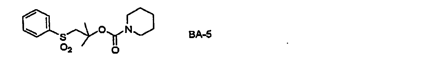

- Since heating is preferable for base proliferation, in case the hologram recording material of the invention employs a base proliferating agent, a heat treatment is preferably executed after a holographic exposure.
- In the following, there will be explained a case where the interference fringe recording component of the invention includes a compound in which an organic compound site, having a function of cleaving a covalent bond by an electron transfer or an energy transfer with a sensitizing dye or a color-developed substance in an excited state, and an organic compound site, having a feature of constituting a color-developed substance when covalent bonded or when released, are covalent bonded.
- In such case, the interference fringe recording component of the invention preferably includes at least a dye precursor represented by the aforementioned general formula (2).
- In the general formula (2), A1 and PD are covalent bonded; A1 represents an organic compound site, having a function of cleaving a covalent bond with PD by an electron transfer or an energy transfer with a sensitizing dye or a color-developed substance in an excited state; and PD represents an organic compound site, having a feature of constituting a color-developed substance when it is covalent bonded with A1 or when it is released by the cleavage of the covalent bond with A1.
- More preferably, A1 is an organic compound site, having a function of cleaving the covalent bond with PD by an electron transfer with a sensitizing dye or a color-developed substance in an excited state.
- PD is preferably a group constituted of a dissociable dye such as a dissociable azo dye, a dissociable azomethine dye, a dissociable oxonol dye or a dissociable arylidene dye, or a dye that can form so-called "leuco dye" such as a triphenylmethane dye or a xanthene (fluorine) dye, and is bonded to A1 by a covalent bond on the chromophore.
- PD is more preferably any one of a dissociable azo dye, a dissociable azomethine dye, a dissociable oxonol dye and a dissociable arylidene dye.
- Preferably PD is colorless, pale-colored or has an absorption at a short wavelength when it is covalent bonded to A1, and is strongly colored or shows a shift of the absorption to a longer wavelength when it is released by a cleavage of the covalent bond with A1.
- Preferred specific examples of PD are shown in the following, but the present invention is not limited to such examples.


- In forming a covalent bond with A1, PD may form a covalent bond with any position of A1 as long as it is on the chromophore, but preferably forms a covalent bond with A1 at an atom indicated by an arrow in the foregoing formulas.
- The dye precursor of the general formula is more preferably represented by any of the general formulas (3-1) to (3-6).
- In the general formulas (3-1) to (3-6), PD has the same meaning as in the general formula (2).
- In the general formula (3-1), R71 represents a hydrogen atom or a substituent (of which preferred examples are same as those for R3), preferably an alkyl group or an aryl group, more preferably a t-butyl group, a methyl group or a phenyl group, and further preferably a methyl group or a t-butyl group.
- R72 represents a substituent (of which preferred examples are same as those for R3), preferably an electron attracting group, and more preferably a nitro group, a sulfamoyl group, a carbamoyl group, an alkoxycarbonyl group, a cyano group or a halogen atom; a71 represents an integer from 0 to 5, and, in case a71 is 2 or larger, plural R72 may be mutually same or different or may be mutually bonded to form a ring. a71 is preferably 1 or 2, and R72 is preferably substituted in 2- or 4-position.
- In the general formula (3-2), R73 represents a substituent (of which preferred examples are same as those for R3), preferably an electron attracting group, more preferably a nitro group, a sulfamoyl group, a carbamoyl group, an alkoxycarbonyl group, a cyano group or a halogen atom and further preferably a nitro group; a72 each independently represents an integer from 0 to 5, and, in case a72 is 2 or larger, plural R73 may be mutually same or different or may be mutually bonded to form a ring. a72 is preferably 1 or 2, and, in case a72 is 1, substitution is preferably on a 2-position, and, in case a72 is 2, the substitution is preferably on 2- and 4-positions or 2- and 6-positions, more preferably on 2- and 6-positions.
- a73 represents 0 or 1.
- In the general formula (3-3), R74 - R77 each independently represents an alkyl group, and they preferably represent methyl groups.
- In the general formula (3-4), R78 and R79 each independently represent a substituent (of which preferred examples are same as those for R3); and R79 preferably represents an alkoxy group, more preferably a methoxy group; a74 and a75 each independently represents an integer from 0 to 5, and, in case a74 or a 75 is 2 or larger, plural R78 or R79 may be mutually same or different or may be mutually bonded to form a ring. Each of a74 and a75 preferably represents 0 to 2, and, a74 is more preferably 0 or 1 while a75 is more preferably 2. In case a75 is 2, R79 is preferably substituted on 3- and 5-positions.
- a76 represents 0 or 1.
- In the general formula (3-5), R80 and R81 each independently represent a hydrogen atom or a substituent (of which preferred examples are same as those for R3), and R80 and R81 may be mutually bonded to form a ring, and a ring to be formed is preferably a benzene ring or a norbornene ring. R80 and R81 not forming a ring are preferably both hydrogen atoms.
- In the general formula (3-6), R82 and R83 each independently represent a substituent (of which preferred examples are same as those for R3), preferably an alkyl group, an alkenyl group or an aryl group. R82 and R83 are preferably mutually bonded to form a ring, and a ring to be formed is preferably a fluorene ring, a dibenzopyran ring, or a tetrahydronaphthalene ring.
- The dye precursor representedby the general formula (2) is preferably represented by the general formula (3-1), (3-2) or (3-4).
- Preferred examples of the dye precursor of the invention represented by the general formulas (3-1) to (3-6) are shown in the following, but the present invention is not limited to such examples.


- In case the interference fringe recording component of the invention includes at least a dye precursor represented by the following general formula (2) or any of (3-1) to (3-6), the hologram recording material of the invention preferably includes a base for the purpose of dissociating a dissociable dye to be generated. The base can be an organic base or an inorganic base, preferably an alkylamine, an aniline, an imidazole, a pyridine, a carbonate salt, a hydroxide salt, a carboxylic acid salt or a metal alkoxide. A polymer containing such base can also be advantageously employed.
- In the following, there will be explained a case where the interference fringe recording component of the invention includes a compound capable of causing a reaction to change a form of the absorption by an electron transfer with a sensitizing dye or a color-developed substance in an excited state.
- The compound capable of causing such change is generally called an "electrochromic compound".
- The electrochromic compound to be employed as the dye precursor in the invention is preferably a polypyrrol (for example preferably polypyrrol, poly(N-methylpyrrol), poly(N-methylindole), or polypyrrolopyrrol), a polythiophene (for example preferably polythiophene, poly(3-hexylthiophene), polyisothianaphthene, polydithienothiophene, poly(3-hexylthiophene), polyisothioanaphthene, polydithienothiophene, or poly(3,4-ethylenedioxy)thiophene), a polyaniline (for example preferably polyaniline, poly(N-naphthylaniline), poly(o-phenylenediamine), poly(aniline-m-sulfonic acid), poly(2-methoxyaniline), poly(oaminophenol), or poly(diallylamine)), a poly(N-vinylcarbazole), a Co-pyridinoporphyrazine complex, a Ni-phenanthroline complex, or a Fe-basophenanthroline complex.
- There is also preferred an electrochromic material such as a viologen, a polyviologen, a lanthanoid diphthalocyanine, a styryl dye, a TNF, a TCNQ/TTF complex, a Ru-trisbipyridyl complex etc.
- The interference fringe recording component of the invention may be available commercially or synthesized by a known method.
- In the hologram recording material of the invention, there can be advantageously employed an electron donating compound capable of reducing a radical cation of a sensitizing dye or a color developed substance, or an electron accepting compound capable of oxidizing a radical anion of a sensitizing dye or a color developed substance.
- Preferred examples of the electron donating compound include an alkylamine (such as triethylamine, tributylamine, trioctylamine, N,N-dimethyldodecylamine, triethanolamine, or triethoxyethylamine), an aniline (such as N,N-dioctylaniline, N,N-dimethylaniline, 4-methoxy-N,N-dibutylaniline, or 2-methoxy-N,N-dibutylaniline), a phenylenediamine (such as N,N,N',N'-tetramethyl-1,4-phenylenediamine, N,N,N',N'-tetramethyl-1,2-phenylenediamine, N,N,N',N'-tetramethyl-1,3-phenylenediamine, or N,N'-dibutylphenylenediamine), a triphenylamine (such as triphenylamine, tri(4-methoxyphenyl)amine, tri(4-dimethylaminophenyl)amine, or TPD), a carbazole (such as N-vinylcarbazole, or N-ethylcarbazole), a phenothiazine (such as N-methylphenothiazine, or N-phenylphenothiazine), a phenoxazine (such as N-methylphenoxazine or N-phenylphenoxazine), a phenazine (such as N,N'-dimethylphenazine, or N,N'-diphenylphenazine), a hydroquinone (for example hydroquinone, 2,5-dimethylhydroquinone, 2,5-dichlorohydroquinone, 2,3,4,5-tetrachlorohydroquinone, 2,6-dichloro-3,5-dicyanohydroquinone, 2,3-dichloro-5,6-dicyanohydroquinone, 1,4-dihydroxynaphthalene, or 9,10-dihydroxynaphthalene),a cathecol(such as cathecol, or 1,2,4-trihydroxybenzene), an alkoxybenzene (such as 1,2-dimethoxybenzene, 1,2-dibutoxybenzene, 1,2,4-tributoxybenzene or 1,4-dihexyloxybenzene), an aminophenol (such as 4-(N,N-diethylamino)phenol or N-octylaminophenol), an imidazole (such as imidazole, N-methylimidazole, N-octylimidazole or N-butyl-2-methylimidazole), a pyridine (such as pyridine, picoline, lutidine, 4-t-butylpyridine, 4-octyloxypyridine, 4-(N,N-dimethylamino)pyridine, 4-(N,N-dibutylamino)pyridine, or 2-(N-octylamino)pyridine), a metalocene (such as ferrocene, titanocene or lutenocene), a metal complex (such as Ru-bisbipyridine complex, Cu-phenanthroline complex, Co-trisbipyridine complex, Fe-EDTA complex, or complexes of Ru, Fe, Re, Pt, Cu, Co, Ni, Pd, W, Mo, Cr, Mn, Ir, Ag etc.) and semiconductor fine particles (for example Si, CdSe, GaP, PbS or ZnS).
- The electron donating compound is more preferably a phenothiazine compound, and most preferably N-methylphenothiazine.
- On the other hand, preferredexamples of the electron accepting compound includes an aromatic compound in which an electron attracting group is introduced (such as 1,4-dinitrobenzene, 1,4-dicyanobenzene, 4,5-dichloro-1,2-dicyanobenzene, 4-nitro-1,2-dicyanobenzene, 4-octanesulfonyl-1,2-dicyanobenzene, or 1,10-dicyanoanthracene), a heterocyclic compound or a heterocyclic compound in which an electron attracting group is introduced (such as pyrimidine, pyrazine, triazine, dichloropyrazine, 3-cyano-pyrazole, 4,5-dicyana-1-methyl-2-octanoylaminoimidazole, 4,5-dicyanoimidazole, 2,4-dimethyl-1,3,4-thiadiazole, 5-chloro-3-phenyl-1,2,4-thiadiazole, 1,3,4-oxadiazole, 2-chlorobenzothiazole, or N-butyl-1,2,4-triazole), an N-alkylpyridinium salt (such as N-butylpyridiniumiodide, N-butylpyridiniumbis(trifluoromethanesulfonyl) imide, N-butyl-3-ethoxycarbonyl-pyridinium butanesulfonate, N-octyl-3-carbamoylpyridinium bis(trifluoromethanesulfonyl) imide, N,N-dimethylviologen di(hexafluorophosphate), or N,N-diphenylviologen bis(bis(trifluoromethanesulfonyl)imide)), a benzoquinone (such as benzoquinone, 2,5-dimethylbenzoquinone, 2,5-dichlorobenzoquinone, 2,3,4,5-tetrachlorobenzoquinone, 2,6-dichloro-3,5-dicyanobenzoquinone, 2,3-dichloro-5,6-dicyanobenzoquinone, naphthoquinone or anthraquinone), an imide (such as N,N'-dioctylpyromellitimide or 4-nitro-N-octylphthalimide), a metal complex (such as Ru-trisbipyridine complex, Ru-bisbipyridine complex, Co-trisbipyridine complex, Cr-trisbipyridine complex, PtCl6 complex, or complexes of Ru, Fe, Re, Pt, Cu, Co, Ni, Pd, W, Mo, Cr, Mn, Ir, Ag etc.) and semiconductor fine particles (for example TiO2, Nb2O5, ZnO, SnO2, Fe2O3, or WO3).
- The electron donating compound preferably has an oxidation potential baser (at the negative side) than an oxidation potential of the sensitizing dye or the color-developed substance or an oxidation potential of an excited state of the sensitizing dye or the color-developed substance, and the electron accepting compound preferably has a reduction potential more precious (at the positive side) than a reduction potential of the sensitizing dye or the color-developed substance or a reduction potential of an excited state of the sensitizing dye or the color-developed substance.
- In the hologram recording material of the invention, a binder is advantageously employed. The binder is usually employed for the purposes of improving a film forming property of the composition, a uniformity of film thickness and a stability in storage. The binder preferably has a satisfactory mutual solubility with the sensitizing dye and the interference fringe recording component.
- The binder is preferably constituted of a thermoplastic polymer soluble in a solvent, which can be employed singly or in a combination of plural kinds.
- The binder may have a reactive site and may be crosslinked or hardened by a reaction with a crosslinking agent, a polymerizable monomer or oligomer. The reactive site in such case can be, for example as a radical reactive site, an ethylenic unsaturated group represented by an acryl group or a methacryl group, also as a cationic reactive site, an oxilane compound, an oxetane compound or a vinyl ether group, and as a polycondensation reactive site, a carboxylic acid, an alcohol or an amine.
- Preferred examples of the binder to be employed in the invention include a polymer of an acrylate or α-alkylacrylate ester or an acid or an interpolymer (such as polymethyl methacrylate, polyethyl methacrylate, or copolymer of methyl methacrylate and another alkyl (meth)acrylate ester), a polyvinyl ester (such as polyvinyl acetate, polyvinyl acetate/acrylate, polyvinyl acetate/methacrylate or hydrolyzed polyvinyl acetate), an ethylene/vinyl acetate copolymer, a saturated or unsaturated polyurethane, a butadiene or isoprene polymer/copolymer, a high-molecular polyoxyethylene of a polyglycol having a weight-averaged molecular weight of about 4, 000 to 1,000,000, an epoxide (such as an epoxide having an acrylate group or a methacrylate group), a polyamide (such as N-methoxymethylpolyhexamethylene adipamide), a cellulose ester (such as cellulose acetate, cellulose acetate succinate or cellulose acetate butyrate), a cellulose ester (such as methyl cellulose, ethyl cellulose, or ethylbenzyl cellulose), polycarbonate, polyvinylacetal (such as polyvinyl butyral or polyvinylformal), polyvinyl alcohol, polyvinylpyrrolidone, and an acid-containing polymer/copolymer functioning as an appropriate binder as disclosed in USP Nos. 3,458,311 and 4,273,857.
- Examples further include a polystyrene polymer or a copolymer with acrylonitrile, maleic anhydride, acrylic acid, methacrylic acid or an ester thereof, a vinylidene chloride copolymer (such as a vinylidene chloride/acrylonitrile copolymer, a vinylidene chloride/methacrylate copolymer, or a vinylidene chloride/vinyl acetate copolymer), polyvinyl chloride and a copolymer thereof (such as polyvinyl chloride/acetate, or a vinyl chloride/acrylonitrile copolymer), polyvinylbenzal synthetic rubber (such as a butadiene/acrylonitrile copolymer, an acrylonitrile/butadiene /styrene copolymer, a methacrylate/acrylonitrile/butadiene/styrene copolymer, a 2-chlorobutadiene-1,3 polymer, chlorinated rubber, a styrene/butadiene or styrene/isoprene/styrene block copolymer), a copolyester (such as a product produced from a reaction product of polymethylene glycol represented by a formula HO (CH2) nOH (in which n represents an integer of 2 to 10) and (1) hexahydroterephthalic acid, sebacic acid and terephthalic acid, (2) terephthalic acid, isophthalic acid and sebacic acid, (3) terephthalic acid and sebacic acid, or (4) terephthalic acid and isophthalic acid, or (5) a copolyester mixture produced from the aforementioned glycol and (i) terephthalic acid, isophthalic acid and sebacic acid, and (ii) terephthalic acid, isophthalic acid, sebacic acid and adipic acid), poly-N-vinylcarbazole or a copolymer thereof, a carbazole-containing polymer disclosed by Kamogawa et al., in Journal of Polymer Science: Polymer Chemistry Edition, 18, p.9-18(1979), and a polycarbonate constituted of a bisphenol and a carbonate ester.
- A fluorine atom-containing polymer is also preferable as a binder of a low refractive index. A preferred example is a polymer including a fluoroolefin as an essential component and one or more unsaturated monomers selected from an alkyl vinyl ether, an alicyclic vinyl ether, a hydroxyvinyl ether, an olefin, a haloolefin, an unsaturated carboxylic acid, an ester thereof, and a vinyl carboxylate ester as a copolymerizing component, and soluble in an organic solvent. It preferably has a weight-averaged molecular weight of 5, 000 to 200, 000 and a fluorine atom content of 5 to 70 wt.%.
- The fluoroolefin in the fluorine atom-containing polymer can be tetrafluoroethylene, chlorotrifluoroethylene, vinyl fluoride or vinylidene fluoride. Also as to other copolymeriztion components, the alkyl vinyl ether can for example be ethyl vinyl ether, isobutyl vinyl ether, or n-butyl vinyl ether; the alicyclic vinyl ether can be cyclohexyl vinyl ether or a derivative thereof; the hydroxyvinyl ether can be cyclohexyl vinyl ether or a derivative thereof; the hydroxyvinyl ether can be hydroxybutyl vinyl ether; the olefin or haloolefin can be ethylene, propylene, isobutylene, vinyl chloride, or vinylidene chloride; the vinyl carboxylate ester can be vinyl acetate or vinyl n-butyrate; and the unsaturated carboxylic acid or an ester thereof can be an unsaturated carboxylic acid such as (meth)acrylic acid or crotonic acid, or a C1 to C18 alkyl ester of (meth)acrylic acid such as methyl (meth)acrylate, ethyl (meth)acrylate, propyl (meth)acrylate, isopropyl (meth)acrylate, butyl (meth)acrylate, hexyl (meth)acrylate, octyl (meth)acrylate or lauryl (meth)acrylate, or a C2 - C8 hydroxyalkyl ester of (meth)acrylic acid such as hydroxyethyl (meth)acrylate or hydroxypropyl (meth)acrylate; N,N-dimethylaminoethyl (meth) acrylate, orN,N-diethylaminoethyl (meth)acrylate. These radical polymerizable monomers may be employed singly or in a combination of two or more kinds, and, if necessary, a part of such monomer may be replaced by another radical polymerizable monomer for example a vinyl compound such as styrene, α-methylstyrene, vinyltoluene or (meth)acrylonitrile. Also as another derivative of the monomer, there can be employed a fluoroolefin containing a carboxylic acid group, or a vinyl ether containing a glycidyl group.
- Examples of the fluorine atom-containing polymer include products of a "Lumiflon" series, having a hydroxyl group and soluble in organic solvents (for example Lumiflon LF200, weight-averaged molecular weight: ca. 50, 000, manufactured by Asahi Glass Co.). The fluorine atom-containing polymers soluble in organic solvents are commercially available also from Daikin Industries Ltd., Central Glass Co., Penwalt Inc. etc. and are likewise usable.
- The binder to be employed in the hologram recording material of the invention preferably has a refractive index equal to or less than 1.5.
- The hologram recording material of the invention may suitably contain, if necessary, additives such as a polymerizable monomer, a polymerizable oligomer, a crosslinking agent, a thermal stabilizer, a plasticizer, a solvent etc.
- Examples of the polymerizable monomer, the polymerizable oligomer, and the crosslinking agent preferably employable in the hologram recording material of the invention are described for example in JP-A No. 2003-82732.
- In the hologram recording material of the invention, a thermal stabilizer may be added in order to improve the stability in the storage.
- Examples of the useful thermal stabilizer include hydroquinone, phenidone, p-methoxyphenol, an alkyl- or aryl-substituted hydroquinone or quinone, cathecol, t-butylcathecol, pyrogallol, 2-naphthol, 2,6-di-t-butyl-p-cresol, phenothiazine and chloranil. Also a dinitrosodimer, described by Pazos in USP No. 4,168,982, is useful.
- The plasticizer is used for regulating an adhesion property, a flexibility, a hardness, a scattering property and other mechanical properties of the hologram recording material. Examples of the plasticizer include triethylene glycol tricaprilate, triethylene glycol bis(2-ethylhexanoate), tetraethylene glycol diheptanoate, diethyl sebacate, dibutyl suberate, tris(2-ethylhexyl) phosphate, tricresyl phosphate and dibutyl phthalate. Also an alcohol or a phenol can be advantageously employed as an additive.
- Components of the hologram recording material of the invention or the composition thereof are preferably present within following ranges, in percentage with respect to the total mass of the composition:
- (reactive) binder, polymerizable monomer, polymerizable oligomer, crosslinking agent: preferably 0 - 95 mass%, more preferably 30 - 95 mass%
- interference fringe recording component: preferably 3 - 70 mass%, more preferably 5 - 70 mass%, further preferably 5 - 50 mass%
- sensitizing dye: preferably 0.001 - 10 mass%, more preferably 0.01 - 10 mass%, furthermore preferably 0.01 - 3, particularly preferably 0.1 - 3 mass%
- electron-donating compound or electron-accepting compound: preferably 0 - 40 mass%, more preferably 0 - 30 mass%.
-
- The hologram recording material of the invention or the composition therefor can be prepared by an ordinary method. For example, it can be prepared from the essential component and other components mentioned above, with an addition of a solvent if necessary.
- For example, the film formation of the hologram recording material of the present invention may be performed by a method of dissolving the binder and respective components in a solvent or the like and coating the obtained solution with use of a spin coater, a bar coater or the like.
- Examples of the solvent include a ketone solvent such as methyl ethyl ketone, methyl isobutyl ketone, acetone or cyclohexanone, an ester solvent such as ethyl acetate, butyl acetate, ethylene glycol diacetate, ethyl lactate or cellosolve acetate, a hydrocarbon solvent such as cyclohexane, toluene or xylene, an ether solvent such as tetrahydrofuran, dioxane, or diethyl ether, a cellosolve solvent such as methyl cellosolve, ethyl cellosolve, butyl cellosolve, or dimethyl cellosolve, an alcohol solvent such as methanol, ethanol, n-propanol, 2-propanol, n-butanol, or diacetone alcohol, a fluorinated solvent such as 2,2,3,3-tetrafluoropropanol, a halogenated hydrocarbon solvent such as dichloromethane, chloroform or 1, 2-dichloroethane, an amide solvent such as N,N-dimethylformamide, and a nitrile solvent such as acetonitrile or propionitrile.
- The hologram recording material of the invention can be prepared by direct coating on a substrate with a spin coater, a roll coater, a bar coater or the like, or by casting into a film followed by a lamination in an ordinary method on a substrate.
- The "substrate" can be any natural or synthetic substrate, which preferably can exist as a flexible or rigid film, a sheet or a plate.
- The substrate is preferably constituted for example of polyethylene terephthalate, polyethylene terephthalate with a resinous undercoating, polyethylene terephthalate subjected to a flame or electrostatic discharge treatment, cellulose acetate, polycarbonate, polymethyl methacrylate, polyester, polyvinyl alcohol or glass.
- The solvent employed may be removed by evaporation at a drying. The removal by evaporation may be executed by heating or under a reduced pressure.
- The film formation of the hologram recording material of the present invention may also be performed by melting the binder containing respective components at a temperature higher than the glass transition temperature or melting point of the binder and melt-extruding or injection-molding the obtained melt. At this time, a reactive crosslinking binder may be used as the binder to cure the film by causing crosslinking after extrusion or molding and thereby increase the film strength. Examples of the crosslinking reaction which can be used here include a radical polymerization reaction, a cationic polymerization reaction, a condensation polymerization reaction and an addition polymerization reaction. Furthermore, the methods described, for example, in JP-A-2000-250382 and JP-A-2000-172154 can also be preferably used.
- In addition, a method of dissolving respective components in a monomer solution for forming the binder, causing thermal polymerization or photopolymerization of the monomer to form a polymer and using the polymer as the binder can also be preferably used. Examples of the polymerization method which can be used here include, similarly to the above, a radical polymerization reaction, a cationic polymerization reaction, a condensation polymerization reaction and an addition polymerization reaction.
- Also a protective layer for intercepting oxygen may be provided on the hologram recording material. The protective layer may be formed by adhering a plastic film or a plastic plate of a polyolefin such as polypropylene or polyethylene, polyvinyl chloride, polyvinylidene chloride, polyvinyl alcohol, polyethylene terephthalate or a cellophane film by electrostatic adhesion or by lamination utilizing an extruder, or it may also be formed by coating a solution of the aforementioned polymer. Also a glass plate may be adhered. Also in order to increase hermeticity a tacking agent or a liquid substance may be made present between the protective layer and the photosensitive film and/or between the substrate and the photosensitive film.
- In case of utilizing the hologram recordingmaterial of the invention for a holographic optical memory, the hologram recording material is preferably free from a shrinkage before and after the hologram recording, in order to improve the S/N ratio at the signal reproduction.
- For this purpose, it is preferable to employ in the hologram recording material of the invention, for example, an expanding agent described in JP-A No. 2000-86914, or a shrinkage-resistant binder described in JP-A Nos. 2000-250382, 2000-172154 and 11-344917.
- It is also preferable to regulate a gap of interference fringes by a diffusing element described in JP-A Nos. 3-46687 and 5-204288 and JP-T No. 9-506441.
- In general, the refractive index of a dye assumes a high value within a longer wavelength range from a vicinity of a wavelength of a linear absorption maximum (λmax), particularly a very high value within a longer wavelength range of about 200 nm from λmax, exceeding 2 in certain dyes and exceeding 2.5 in certain cases. On the other hand, a non-dye organic compound such as a binder polymer has a refractive index of about 1.4 to 1.6.
- In the holography, it is preferable in principle that a reproducing wavelength is same as a recording wavelength.
- Therefore, in the hologram recording material of the invention, it is preferable that the refractive index of the dye formed from the interference fringe recording component becomes largest in the vicinity of the wavelength of the laser employed for recording (reproduction). The dye formed from the interference fringe recording component more preferably has, in a dye single film, a refractive index at the recording wavelength of 1.7 or higher, further preferably 1.8 or higher and most preferably 2 or higher.
- Thus, in the aforementioned method for the hologram recording material of the invention, by causing a color development (absorption shift to a longer wavelength) either by an excitation energy acquiredby the sensitizing dye through a holographic exposure in a first step or by an excitation energy acquired by the color-developed substance in a second step, it is possible to modulate the refractive index more significantly between a light region and a dark region in the interference, in comparison with the known photopolymer processes described for example in patent references 1 - 3 and 5 - 8.
- Besides, the hologram recording method of the invention, including a first step of forming a latent image by a holographic exposure and a second step of amplifying such latent image thereby modulating the refractive index to form interference fringes, is capable of a recording with a very high sensitivity in comparison with the known methods.
- Also the hologram recording material of the invention, being free from a material displacement or a polymerization in the interference fringe recording as in a photopolymer method, can exclude a trade-off restriction and achieve a high sensitivity, a low shrinkage and a satisfactory storability at the same time. Also, multiplex recording can be executed many times since the recording itself does not involve polymerization, and, an exposure amount can be maintained constant in any of the multiplex recording, so that a wide dynamic range can be realized. In particular, the method of the invention utilizing the latent image amplification is advantageous in the adaptability to the multiplex recording.
- These factors are advantageous for achieving a high capacity, simplifying the recording system and improving the S/N ratio.
- On the other hand, in comparison with a recording method utilizing a change in orientation of a compound having a birefringent property such as an azobenzene polymer, as disclosed in the patent reference 4, the method of the invention has a high sensitivity because of a high quantum yield, and also enables a non-destructive reproduction by decomposing the sensitizing dye in the hologram recording, in the thermal or optical fixation after the recording, or in the first or second step, thereby providing an excellent storability.
- As explained in the foregoing, the hologram recording material of the invention provides a totally novel recording method fundamentally free from the aforementioned drawbacks and capable of realizing, in particular, a high sensitivity, a low shrinkage, a satisfactory storability, a dry processing and a multiplex recording characteristics at the same time, and is preferably applied to an optical recording medium (holographic optical memory). In particular, the hologram recording material of the invention is further preferably applied to a dry unrewritable method. Also there is preferred an unrewritable hologram recording method described in (A-36) mentioned in the foregoing.
- In case of utilizing the hologram recording material of the invention as an optical recording medium, the hologram recording material is stored preferably in a light-tight cartridge. It is also preferable to provide the hologram recording material, on a front surface and/or a rear surface thereof, with a light-shielding filter capable of intercepting a part of ultraviolet, visible and infrared wavelength ranges other than the wavelength of the recording light and the reproducing light.
- In case of employing the hologram recording material of the invention as an optical recording medium, such optical recording medium can be of any shape such as a disk, a card or a tape.
- Also the hologram recording material of the invention can be advantageously applied, in addition to the optical recording medium, for example to a three-dimensional display hologram, a holographic optical element (HOE, such as a head-up display (HUD) for an automobile, a pickup lens for an optical disk, a head-mount display, a color filter for liquid crystal display, a reflection plate for a reflective liquid crystal display, a lens, a diffraction grating, an interference filter, an optical fiber coupler, a photodeflector for facsimile, and a window pane for construction), a cover for a book or a magazine, a display such as a POP, a gift, a credit card for antiforging, a banknote, a package etc.
- In the following, examples of the present invention will be explained, but the present invention is not limited to such examples.
- Under a red light, a sensitizing dye, an electron donating compound, an interference fringe recording component, an additive and a binder PMMA-EA (polymethyl methacrylate-5% ethyl acrylate copolymer, Mw: 101,000) shown in Table 1 were dissolved in methylene chloride of 2 to 4 times amount (acetone or acetonitrile being also employed if necessary) to obtain compositions A101 - A110 for hologram recording material.
- Percentages are shown in wt.% with respect to the binder PMMA-EA.


Sample Sensitizing dye Electron donating compd. Interference fringe recording component Additive A101 D-91 4 % - I-103 50% + R-3 10% SO-1 8% A102 D-95 8 % - 1-103 50% + R-3 10% SO-1 8% A103 D-95 4 % ED-1 36 % I-103 50% + R-3 10% - A104 D-101 30 % - I-103 50% + R-3 10% SO-2 36% A105 D-107 30 % - I-103 50% + R-3 10% SO-2 36% A106 D-115 0.5% ED-1 42 % I-103 50% + R-3 10% SO-3 8% A107 D-118 1.6% ED-1 42 % 1-103 50% + R-3 10% SO-3 8% A108 D-117
0.84%ED-1 42 % PB-3 20% + DD-47 10% - A109 D-118 1.6% ED-1 42 % E-12 25 % trioctylamine 10% A110 D-101 30 % - E-13 25 % trioctylamine 10% - Each of the compositions A101 - A110 for the hologram recording material was blade coated on a glass substrate (superposed coating if necessary) to obtain a thickness of about 80 µm to form a photosensitive layer, and was dried by heating for 3 minutes at 40°C for removing the solvent. Then the photosensitive layer was covered with a TAC film to obtain hologram recording materials A101 - A110.
- Also as a comparative example, there was prepared a hologram recording material of radical polymerization photopolymer type, described in Example 1 of JP-A No. 6-43634 (corresponding to USP 4,942,112).
- The hologram recording material was recorded by an exposure in a two-beam optical system for transmission hologram recording as shown in Fig. 1, utilizing a second harmonic wave of a YAG laser (wavelength: 532 nm, output: 2 W) as a light source. An object light and a reference light formed an angle of 30°. The light beamhad a diameter of 0.6 cm and an intensity of 8 mW/cm2, and the exposure was made by varying a holography exposure time within a range of 0.1 to 400 seconds (range of irradiation energy of 0.8 to 3200 mJ/cm2) . During the holographic exposure, a beam of 632 nm of a He-Ne laser was passed with a Bragg's angle at the center of the exposure area, and a ratio of a diffracted light to an incident light (diffraction efficiency) was measure on real-time basis.
- Results of evaluations of the maximum diffraction efficiency and the shrink rate, on the hologram recording materials A101 - A110, are shown in Table 2. The shrink rate is a ratio of film thickness before and after the recording.
Sample Maximum diffraction efficiency Shrink rate A101 73 % < 0.01 % A102 76 % < 0.01 % A103 76 % < 0.01 % A104 71 % < 0.01 % A105 71 % < 0.01 % A106 73 % < 0.01 % A107 75 % < 0.01 % A108 70 % < 0.01 % A109 72 % < 0.01 % A110 72 % < 0.01 % comp. ex. 69 % 5.1 % - Table 2 indicates that the known comparative example described in JP-A No. 6-43634 had a high diffraction efficiency but resulted in a large shrinkage exceeding 5 % because it was based on a photopolymer method involving a radical polymerization, thus showing an extreme deterioration in the S/N ratio, and was unsuitable particularly for a holographic memory. On the other hand, it is indicated that the hologram recording materials A101 - A110 of the invention, based on a recording method which was totally different from that of the known hologram recording materials and which executed a hologram recording by a refractive index modulation by a color developing reaction instead of a material transfer or a polymerization, could achieve a high diffraction efficiency and an extremely small shrink rate not exceeding 0.01 % at the same time, and was particularly suitable for a holographic memory.
- It is also identified that the hologram recording material of the present invention showed a linear increase in Δn (modulation amount of refractive index, calculated from diffraction efficiency and film thickness according to Kogelnick's equation) in proportion to the exposure amount (mJ/cm2), thus being advantageous for multiplex recording.
- In practice, the hologram recording material of the invention was subjected to a multiplex hologram recording of 10 times in a same position with an exposure amount each equal to 1/10 of the exposure amount providing the maximum diffraction efficiency andwith a reference light angle changed by 2° for each exposure, and it was confirmed that each obj ect light could be reproduced by a reproducing light irradiation changed by 2° for each time. Thus the hologram recording material of the invention is capable of multiplex recording with a same exposure amount, thus being suitable for multiplex recording. Stated differently, the hologram recording material of the invention is capable of multiplex recording of many times, thus achieving a recording of a high density (capacity) .
- On the other hand, in the hologram recording materials of JP-A No. 6-43634 and other known photopolymer methods, the polymerization of photopolymer progresses to retard the monomer displacement required for recording, in a latter period of the multiplex recording, thus requiring a larger exposure amount for a same recording in comparison with an early period of the multiplex recording, and constituting a difficulty in increasing the level of multiplicity or the recording density.
- In the samples A101 - A110, similar effects could be obtained also in case of changing the sensitizing dye to D-1, D-8, D-17, D-22, D-31, D-33, D-34, D-46, D-49, D-50, D-55, D-74, D-87, D-93, D-94, D-97, D-100, D-116, D-119, D-120, or D-121 or changing the binder to polymethyl methacrylate (Mw: 996,000, 350,000 or 120, 000) , methyl methacrylate-butyl methacrylate copolymer (Mw: 75,000), polyvinyl acetate (Mw: 83,000) or polycarbonate.
- Furthermore, in the samples A101 - A107, similar effects could be obtained also in case of changing the acid generating agent of the interference fringe recording component to 2-(4'-methoxyphenyl)-4,6-bis(trichloromethyl)-1,3,5-triazine, 4-diethylaminophenyl-diazonium tetrafluoroborate, di(t-butylphenyl)iodonium tetra(pentafluorophenyl)borate, tris(4-methylphenyl)sulfonium tetra(pentafluorophenyl)borate, triphenylsulfonium methanesulfonate, triphenylsulfonium perfluoropentanoate, bis(1-(4-diphenylsulfonium) phenylsulfideditriflato, benzoin tosylate, 2,6-dinitrobenzyl tosylate, N-tosylphthalic imide, 1-101 or 1-107, or by changing the acid-induced color forming dye precursor of the interference fringe recording component to R-1, R-2, R-4, R-6 or R-7.
- Furthermore, similar effects could be obtained also in case of changing, in the sample A103, the base generating agent of the interference fringe recording component to PB-4, PB-8, PB-10, PB-12, PB-13, PB-19, PB-22, PB-32, PB-33, or PB-52, or, in the sample A108, changing the base-induced color forming dye precursor (undissociated substance of dissociable dye) to DD-1, DD-4, DD-7, DD-10, DD-16, DD-23, DD-25, DD-35, DD-39, DD-43, DD-47, DD-48, or DD-49.
- Furthermore, similar effects could be obtained also in case of changing, in the samples A109 and A110, the interference fringe recording component to E-4, E-5, E-15, E-16, E-17, E-18, E-24, E-25, E-28, E-29, E-32, E-33, E-37, E-38, E-42 or E-44.
- Under a red light, a sensitizing dye, an electron donating compound, an interference fringe recording component, an additive and a binder PMMA-EA (polymethyl methacrylate-5% ethyl acrylate copolymer, Mw: 101,000) shown in Table 3 were dissolved in methylene chloride of 2 to 4 times amount (acetone or acetonitrile being also employed if necessary) to obtain compositions B101 - B104 for hologram recording material.
- Percentages are shown in wt.% with respect to the binder PMMA-EA.


Sample Sensitizing dye Electron donating compd. Interference fringe recording component Additive B101 D-115
0.5 %ED-1 42 % I-104 50% + R-3 10% SO-3 8% B102 D-118
1.6 %ED-1 42 % I-104 50% + R-3 10% SO-3 8% B103 D-117
0.84%ED-1 42 % PB-3 20% + DD-47 10% - B104 D-118
1.6 %ED-1 42 % E-12 25 % trioctylamine 10% - Each of the compositions B101 - B104 for the hologram recording material was blade coated on a glass substrate (superposed coating if necessary) to obtain a thickness of about 80 µm to form a photosensitive layer, and was dried by heating for 3 minutes at 40°C for removing the solvent. Then the photosensitive layer was covered with a TAC film to obtain hologram recording materials 101 - 104.
- The hologram recording material was recorded by an exposure in a two-beam optical system for transmission hologram recording as shown in Fig. 1, utilizing a second harmonic wave of a YAG laser (wavelength: 532 nm, output: 2 W) as a light source. An object light and a reference light formed an angle of 30°. The light beam had a diameter of 0.6 cm and an intensity of 8 mW/cm2, and the exposure was made by varying a holography exposure time within a range of 0.1 to 40 seconds (range of irradiation energy of 0.08 to 320 mJ/cm2). During the holographic exposure, a beam of 632 nm of a He-Ne laser was passed with a Bragg' s angle at the center of the exposure area, and a ratio of a diffracted light to an incident light (diffraction efficiency) was measure on real-time basis. Also each sample was flush irradiated over the entire area with a light of a wavelength range of 370 - 410 nm (second step) and a diffraction efficiency was measured.
- Results of evaluations of the diffraction efficiency after the holographic exposure in the first step, the maximum diffraction efficiency to the exposure after the light irradiation in the second step, and the shrink rate (calculated from film thickness before and after the recording) , on the hologram recording materials B101 - B104, are shown in Table 4.
Sample Diffraction efficiency η after 1st step Max. diffraction efficiency η after 2nd step Shrink rate Amplification rate B-101 14 % 72 % < 0.01% 5.9 B-102 15 % 73 % < 0.01% 6.4 B-103 14 % 70 % < 0.01% 5.1 B-104 14 % 71 % < 0.01% 4.6 comp. ex. Diffraction efficiency η / 69% 5.1 % - - Table 4 indicates that the known comparative example described in JP-A No. 6-43634 had a high diffraction efficiency but resulted in a large shrinkage exceeding 5 % because it was based on a photopolymer method involving a radical polymerization, thus showing an extreme deterioration in the S/N ratio, and was unsuitable particularly for a holographic memory. On the other hand, it is indicated that the hologram recording materials B101 - B104 of the invention, based on a recording method which was totally different fromthat of the known hologram recording materials and which executed a hologram recording by a refractive index modulation by a color developing reaction instead of a material transfer or a polymerization, could achieve a high diffraction efficiency and an extremely small shrink rate not exceeding 0.01 % at the same time, and was particularly suitable for a holographic memory.
- Also as indicated in Table 4, in the hologram recording material of the invention, the amount of irradiation in the first step can be made 1/5 to 1/6 of that in case the second step is not employed. The second step, which can be executed in a collective exposure, achieves an amplification of the refractive index modulation recording based on the color-developed substance formed in the first step as a latent image and utilizing a self-sensitizing color formation of the color-developed substance itself in the second step, thereby enabling a shortening of the first step or namely an increase in the sensitivity.
- A sensitivity increase by such amplification is naturally not possible in the known materials.
- It is also identified that the hologram recording material of the present invention showed a linear increase in Δn (modulation amount of refractive index, calculated from diffraction efficiency and film thickness according to Kogelnick's equation) in proportion to the exposure amount (mJ/cm2), thus being advantageous for multiplex recording.
- In practice, the hologram recording material of the invention was subj ected to a multiplex hologram recording, by a multiplex recording of 10 times in a same position with an exposure amount each equal to 1/10 of the exposure amount in the aforementioned first step and with a reference light angle changed by 2° for each exposure (first step) , followed by a flush irradiation with a light of a wavelength range of 370 - 410 nm (second step), and it was confirmed that each object light could be reproduced by a reproducing light irradiation changed by 2° for each time. Thus the hologram recording material of the invention is capable of multiplex recording with a same exposure amount, thus being suitable for multiplex recording. Stated differently, the hologram recording material of the invention is capable of multiplex recording of many times, thus achieving a recording of a high density (capacity).
- On the other hand, in the hologram recording materials of JP-ANo. 6-43634 and other known photopolymer methods, the polymerization of photopolymer progresses to retard the monomer displacement required for recording, in a latter period of the multiplex recording, thus requiring a larger exposure amount for a same recording in comparison with an early period of the multiplex recording, and constituting a difficulty in increasing the level of multiplicity or the recording density.
- In the hologram recording materials (samples) B101 - B104, similar effects could be obtained also in case of changing the sensitizing dye to D-1, D-8, D-17, D-22, D-31, D-33, D-34, D-46, D-49, D-50, D-55, D-74, D-87, D-91, D-93, D-94, D-95, D-97, D-100, D-101, D-107, D-116, D-119, D-120 or D-121, or changing the binder to polymethyl methacrylate (Mw: 996,000, 350,000 or 120,000), methyl methacrylate-butyl methacrylate copolymer (Mw: 75,000) or polyvinyl acetate (Mw: 83,000).
- Furthermore, in the samples B101 and B102, similar effects could be obtained also in case of changing the acid generating agent of the interference fringe recording component to 2-(4'-methoxyphenyl)-4,6-bis(trichloromethyl)-1,3,5-triazine, 4-diethylaminophenyl-diazonium tetrafluoroborate, di(t-butylphenyl)iodonium tetra(pentafluorophenyl)berate, tris(4-methylphenyl)sulfonium tetra(pentafluorophenyl)borate, triphenylsulfonium methanesulfonate, triphenylsulfonium perfluoropentanoate, bis(1-(4-diphenylsulfonium) phenylsulfideditriflato, benzoin tosylate, 2,6-dinitrobenzyl tosylate, N-tosylphthalic imide, I-101, I-102 or I-103, or, in the samples B101 and B102, by changing the acid-induced color forming dye precursor of the interference fringe recording component to R-1, R-2, R-4, R-6 or R-7.
- Furthermore, similar effects could be obtained also in case of changing, in the sample B103, the base generating agent of the interference fringe recording component to PB-4, PB-8, PB-10, PB-12, PB-13, PB-19, PB-22, PB-32, PB-33, or PB-52, or, in the sample B103, changing the base-induced color forming dye precursor (undissociated substance of dissociable dye) to DD-1, DD-4, DD-7, DD-10, DD-16, DD-23, DD-25, DD-35, DD-39, DD-43, DD-47, DD-48, or DD-49.
- Furthermore, similar effects could be obtained also in case of changing, in the sample B104, the interference fringe recording component to E-4, E-5, E-13, E-15, E-16, E-18, E-24, E-25, E-28, E-29, E-32, E-33, E-37, E-38, E-42 or E-44.
- In the foregoing, the flush exposure was executed with a light of an optimumwavelength for respective system, and the electron donating compound was changed to an optimum one if necessary.
- The present application claims foreign priority based on Japanese Patent Application Nos. JP2003-298936 and JP2003-300059, filed August 22, 2003 and August 25, 2003, respectively, the contents of which is incorporated herein by reference.
Claims (37)
- A hologram recording method, which comprises:wherein the hologram recording method employs a nonwritable process.subjecting a sensitizing dye to holographic exposure so that the sensitizing dye absorbs light and is transformed into an excited state;effecting a chemical reaction comprising a coloring reaction, the coloring reaction involving one of electron transfer and energy transfer from the excited state, so as to form a hologram,
- The hologram recording method according to claim 1, wherein the holographic exposure is not followed by any wet processing.
- A hologram recording material composition comprising: a sensitizing dye which is subjected to holographic exposure to absorb light so that the sensitizing dye is transformed into an excited state; and a dye precursor which develops a color when one of electron and energy transfers from the excited state of the sensitizing dye.
- The hologram recording material composition according to claim 3, wherein the dye precursor is capable of becoming a colored material having absorption at a longer wavelength than original state when one of electron and energy transfers from the excited state of the sensitizing dye.
- The hologram recording material composition according to claim 3, which is a phase hologram recording material composition capable of recording an interference fringe by refractive index modulation.
- The hologram recording material composition according to claim 3, wherein the dye precursor forms a colored material which has no absorption in a wavelength of hologram-reproducing light but has absorption in a longer wavelength range than the wavelength of hologram-reproducing light.
- The hologram recording material composition according to claim 3, wherein the dye precursor is an acid-induced color-forming dye precursor, and the hologram recording material further comprises an acid generator.
- The hologram recording material composition according to claim 7, wherein the dye formed from the acid-induced color-forming dye precursor is a xanthene dye, fluorane dye or triphenylmethane dye.
- The hologram recording material composition according to claim 3, wherein the dye precursor is a base-induced color-forming dye precursor, and the hologram recording material composition further comprises a base generator.
- The hologram recording material composition according to claim 9, wherein the base-induced color-forming dye precursor is an undissociated form of dissociative azo dye, dissociative azomethine dye, dissociative oxonol dye, dissociative xanthene dye, dissociative fluorane dye or dissociative triphenylmethane dye.
- The hologram recording material composition according to claim 3, wherein the dye precursor is represented by the following general formula (2): A1-PD
wherein A1 and PD are covalently bonded to each other; A1 represents an organic compound moiety capable of severing the covalent bonding to PD when one of electron and energy transfers from the excited state of the sensitizing dye; and PD represents an organic compound moiety which differs in absorption form between when covalently bonded to A1 and when severed and released from the covalent bonding to A1. - The hologram recording material composition according to claim 3, which comprises an electron-donating compound capable of reducing a radical cation of the sensitizing dye.
- The hologram recording material composition according to claim 12, wherein the electron-donating compound is a phenothiazine.
- A hologram recording material comprising a hologram recording material composition according to claim 3.
- The hologram recording method according to claim 1, which is a volume phase hologram recording method.
- The hologram recording method according to claim 1, which is capable of multi-recording wherein a holographic exposure amount in each of the multi-recording is kept constant.
- An optical recording medium comprising a hologram recording material composition according to claim 3.
- The optical recording medium according to claim 17, which is kept in a light-shielding cartridge during storage.
- A three-dimensional display comprising a hologram recording material according to claim 14.
- A holographic optical element comprising a hologram recording material according to claim 14.
- The hologram recording method according to claim 1, comprising: a first step of forming a latent image by holographic exposure; and a second step of amplifying the latent image to form an interference fringe, wherein the first and second steps are effected in a dry process.
- The hologram recording method according to claim 21, wherein in the second step, the interference fringe is formed due to refractive index modulation by amplifying the latent image.
- The hologram recording method according to claim 21, wherein the second step is triggered by at least one of irradiation with light, application of heat, application of electric field and application of magnetic field.
- The hologram recording method according to claim 21, wherein the first step comprises forming as a latent image a colored material having no absorption in the wavelength of hologram-reproducing light, and the second step comprises irradiating the latent image of the colored material with light having a different wavelength from that of holographic exposure so that the colored material is self-sensitized or self-amplified to record an interference fringe as refractive index modulation.
- The hologram recording method according to claim 21, which employs a nonrewritable process.
- A hologram recording material which allows hologram recording by a hologram recording method according to claim 21, wherein the hologram recording material comprises:1) a sensitizing dye which absorbs light at holographic exposure of the first step to produce an excited state; and2) an interference fringe recording component comprising a dye precursor which can form a colored material having absorption in a longer wavelength than the original state and no absorption in the wavelength of hologram-reproducing light, the interference infringe recording component being capable of recording an interference fringe using refractive index modulation by color development which occurs via the step of transfer of electron or energy from the excited state of sensitizing dye or colored material.
- The hologram recording material according to claim 26, wherein the dye precursor contained in the interference fringe recording component can form a colored material having absorption in a longer wavelength than the original state, no absorption in the wavelength of hologram-reproducing light and an absorption maximum in the range between the wavelength of hologram-reproducing light and the wavelength 200 nm shorter than the wavelength of hologram-reproducing light.
- The hologram recording material according to claim 26, wherein the interference fringe recording component comprises: an acid-induced color-forming dye precursor as a dye precursor; and an acid generator.
- The hologram recording material according to claim 26, wherein the interference fringe recording component comprises: a base-induced color-forming dye precursor as a dye precursor; and a base generator.
- The hologram recording material according to claim 26, comprising one of: an electron-donating compound capable of reducing a radical cation of colored material produced by the sensitizing dye or dye precursor; and an electron-accepting compound capable of oxidizing a radical anion of colored material produced by the sensitizing dye or dye precursor.
- The hologram recording material according to claim 30, comprising a phenothiazine as an electron-donating compound.
- The hologram recording method according to claim 21, which involves volume phase hologram recording.
- The hologram recording method according to claim 21, which comprises performing multi-hologram recording 10 or more times to form a latent image at the first step and then forming an interference fringe from the latent image at the second step.
- The hologram recording method according to claim 33, wherein a holographic exposure amount in each of the multi-hologram recording in the first step is kept constant.
- An optical recording medium comprising a hologram recording material according to claim 26.
- The optical recordingmedium according to claim 35, which is kept in a light-shielding cartridge during storage.
- The hologram recording method according to claim 1, further comprising a step of amplifying the latent image formed by the chemical reaction step.
Applications Claiming Priority (4)
| Application Number | Priority Date | Filing Date | Title |
|---|---|---|---|
| JP2003298936 | 2003-08-22 | ||
| JP2003298936 | 2003-08-22 | ||
| JP2003300059 | 2003-08-25 | ||
| JP2003300059 | 2003-08-25 |
Publications (2)
| Publication Number | Publication Date |
|---|---|
| EP1508833A2 true EP1508833A2 (en) | 2005-02-23 |
| EP1508833A3 EP1508833A3 (en) | 2006-07-05 |
Family
ID=34067425
Family Applications (1)
| Application Number | Title | Priority Date | Filing Date |
|---|---|---|---|
| EP04019952A Withdrawn EP1508833A3 (en) | 2003-08-22 | 2004-08-23 | Hologram recording material composition, hologram recording material and hologram recording method |
Country Status (2)
| Country | Link |
|---|---|
| US (1) | US20050046915A1 (en) |
| EP (1) | EP1508833A3 (en) |
Cited By (4)
| Publication number | Priority date | Publication date | Assignee | Title |
|---|---|---|---|---|
| WO2006044243A2 (en) * | 2004-10-13 | 2006-04-27 | General Electric Company A Corporation Of The State Of New York | Holographic storage medium |
| EP1580597A3 (en) * | 2004-03-26 | 2006-07-12 | Fuji Photo Film Co., Ltd. | Hologram recording material, hologram recording method and optical recording medium |
| EP1696266A2 (en) * | 2005-02-25 | 2006-08-30 | Fuji Photo Film Co., Ltd. | Hologram recording material and optical recording medium |
| KR20200074026A (en) * | 2018-12-14 | 2020-06-24 | 주식회사 엘지화학 | Photopolymer composition |
Families Citing this family (15)
| Publication number | Priority date | Publication date | Assignee | Title |
|---|---|---|---|---|
| US7771915B2 (en) * | 2003-06-27 | 2010-08-10 | Fujifilm Corporation | Two-photon absorbing optical recording material and two-photon absorbing optical recording and reproducing method |
| EP1510862A3 (en) * | 2003-08-25 | 2006-08-09 | Fuji Photo Film Co., Ltd. | Hologram recording method and hologram recording material |
| JP2005274610A (en) * | 2004-03-22 | 2005-10-06 | Fuji Xerox Co Ltd | Hologram-recording medium and recording method |
| JP4649158B2 (en) * | 2004-09-30 | 2011-03-09 | 富士フイルム株式会社 | Hologram recording method |
| EP1696265A2 (en) * | 2005-02-23 | 2006-08-30 | Fuji Photo Film Co., Ltd. | Hologram recording material, hologram recording method, optical recording medium, and dye therefor |
| US7388695B2 (en) * | 2005-03-16 | 2008-06-17 | General Electric Company | Data storage devices and methods |
| US7524590B2 (en) * | 2005-12-07 | 2009-04-28 | General Electric Company | Methods for storing holographic data and articles having enhanced data storage lifetime derived therefrom |
| US7678507B2 (en) * | 2006-01-18 | 2010-03-16 | Inphase Technologies, Inc. | Latent holographic media and method |
| US8808944B2 (en) * | 2006-03-15 | 2014-08-19 | General Electric Company | Method for storing holographic data |
| MX2009003560A (en) * | 2006-10-04 | 2009-06-23 | Australia Reserve Bank | Security document containing an authentication device. |
| US8084168B2 (en) * | 2008-12-23 | 2011-12-27 | General Electric Company | Holographic storage devices with complementary data layer and use thereof |
| US9093082B2 (en) * | 2008-12-23 | 2015-07-28 | General Electric Company | Data storage devices and methods |
| US20100157776A1 (en) * | 2008-12-23 | 2010-06-24 | General Electric Company | Vertically tracked data storage device and method |
| US8182966B2 (en) * | 2008-12-23 | 2012-05-22 | General Electric Company | Data storage devices and methods |
| US20100157774A1 (en) * | 2008-12-23 | 2010-06-24 | General Electric Company | Data storage systems and methods |
Citations (9)
| Publication number | Priority date | Publication date | Assignee | Title |
|---|---|---|---|---|
| US3784378A (en) * | 1971-10-18 | 1974-01-08 | Du Pont | Double-exposure method for producing reverse images in photopolymers |
| US4288861A (en) * | 1977-12-01 | 1981-09-08 | Formigraphic Engine Corporation | Three-dimensional systems |
| US5484927A (en) * | 1992-04-13 | 1996-01-16 | E. I. Du Pont De Nemours And Company | Visible dye photosensitizers derived from tropinone |
| EP0762208A2 (en) * | 1995-09-08 | 1997-03-12 | Konica Corporation | Light sensitive composition, presensitized lithographic printing plate and image forming method employing the printing plate |
| WO2001096409A2 (en) * | 2000-06-15 | 2001-12-20 | 3M Innovative Properties Company | Multiphoton photosensitization system |
| US20020064728A1 (en) * | 1996-09-05 | 2002-05-30 | Weed Gregory C. | Near IR sensitive photoimageable/photopolymerizable compositions, media, and associated processes |
| US6432610B1 (en) * | 1998-09-08 | 2002-08-13 | Regents Of The University Of California | Dye precursor molecules chemically reactive with the light-altered form of light-sensitive molecules to form stable fluorescent dye, particularly for optical memories including two-photon three-dimensional optical memories |
| US20020182530A1 (en) * | 2001-02-01 | 2002-12-05 | Fuji Photo Film Co., Ltd. | Photopolymerizable composition and recording material |
| EP1471387A2 (en) * | 2003-03-31 | 2004-10-27 | Fuji Photo Film Co., Ltd. | Photosensitive composition and compound used thereof |
Family Cites Families (16)
| Publication number | Priority date | Publication date | Assignee | Title |
|---|---|---|---|---|
| US3442566A (en) * | 1966-03-10 | 1969-05-06 | Hughes Aircraft Co | Color holography |
| US3510300A (en) * | 1966-05-24 | 1970-05-05 | Horizons Research Inc | Process for making latent dye salt image visible |
| US3615454A (en) * | 1968-06-26 | 1971-10-26 | Du Pont | Process for imaging and fixing radiation-sensitive compositions by sequential irradiation |
| US4942112A (en) * | 1988-01-15 | 1990-07-17 | E. I. Du Pont De Nemours And Company | Photopolymerizable compositions and elements for refractive index imaging |
| US5543251A (en) * | 1990-06-29 | 1996-08-06 | E. I. Du Pont De Nemours And Company | Method of recording plural holographic images into a holographic recording material by temporal interleaving |
| US5989269A (en) * | 1996-08-30 | 1999-11-23 | Vts Holdings L.L.C. | Method, instruments and kit for autologous transplantation |
| JP3786480B2 (en) * | 1996-10-14 | 2006-06-14 | Jsr株式会社 | Photocurable resin composition |
| JP4075141B2 (en) * | 1998-06-30 | 2008-04-16 | ソニー株式会社 | Hologram image recording medium cartridge |
| US20030129501A1 (en) * | 2002-01-04 | 2003-07-10 | Mischa Megens | Fabricating artificial crystalline structures |
| US7582390B2 (en) * | 2003-05-23 | 2009-09-01 | Fujifilm Corporation | Two-photon absorbing polymerization method, two-photon absorbing optical recording material and two-photon absorbing optical recording method |
| US7771915B2 (en) * | 2003-06-27 | 2010-08-10 | Fujifilm Corporation | Two-photon absorbing optical recording material and two-photon absorbing optical recording and reproducing method |
| EP1510862A3 (en) * | 2003-08-25 | 2006-08-09 | Fuji Photo Film Co., Ltd. | Hologram recording method and hologram recording material |
| JP2005275273A (en) * | 2004-03-26 | 2005-10-06 | Fuji Photo Film Co Ltd | Hologram recording material, hologram recording method, and optical recording medium |
| JP4649158B2 (en) * | 2004-09-30 | 2011-03-09 | 富士フイルム株式会社 | Hologram recording method |
| JP2006235087A (en) * | 2005-02-23 | 2006-09-07 | Fuji Photo Film Co Ltd | Hologram recording material, hologram recording method, optical recording medium, and method of recording to optical recording medium |
| JP2007233155A (en) * | 2006-03-02 | 2007-09-13 | Fujifilm Corp | Hologram recording material, hologram recording method and optical recording medium |
-
2004
- 2004-08-20 US US10/921,937 patent/US20050046915A1/en not_active Abandoned
- 2004-08-23 EP EP04019952A patent/EP1508833A3/en not_active Withdrawn
Patent Citations (9)
| Publication number | Priority date | Publication date | Assignee | Title |
|---|---|---|---|---|
| US3784378A (en) * | 1971-10-18 | 1974-01-08 | Du Pont | Double-exposure method for producing reverse images in photopolymers |
| US4288861A (en) * | 1977-12-01 | 1981-09-08 | Formigraphic Engine Corporation | Three-dimensional systems |
| US5484927A (en) * | 1992-04-13 | 1996-01-16 | E. I. Du Pont De Nemours And Company | Visible dye photosensitizers derived from tropinone |
| EP0762208A2 (en) * | 1995-09-08 | 1997-03-12 | Konica Corporation | Light sensitive composition, presensitized lithographic printing plate and image forming method employing the printing plate |
| US20020064728A1 (en) * | 1996-09-05 | 2002-05-30 | Weed Gregory C. | Near IR sensitive photoimageable/photopolymerizable compositions, media, and associated processes |
| US6432610B1 (en) * | 1998-09-08 | 2002-08-13 | Regents Of The University Of California | Dye precursor molecules chemically reactive with the light-altered form of light-sensitive molecules to form stable fluorescent dye, particularly for optical memories including two-photon three-dimensional optical memories |
| WO2001096409A2 (en) * | 2000-06-15 | 2001-12-20 | 3M Innovative Properties Company | Multiphoton photosensitization system |
| US20020182530A1 (en) * | 2001-02-01 | 2002-12-05 | Fuji Photo Film Co., Ltd. | Photopolymerizable composition and recording material |
| EP1471387A2 (en) * | 2003-03-31 | 2004-10-27 | Fuji Photo Film Co., Ltd. | Photosensitive composition and compound used thereof |
Cited By (9)
| Publication number | Priority date | Publication date | Assignee | Title |
|---|---|---|---|---|
| EP1580597A3 (en) * | 2004-03-26 | 2006-07-12 | Fuji Photo Film Co., Ltd. | Hologram recording material, hologram recording method and optical recording medium |
| WO2006044243A2 (en) * | 2004-10-13 | 2006-04-27 | General Electric Company A Corporation Of The State Of New York | Holographic storage medium |
| WO2006044243A3 (en) * | 2004-10-13 | 2007-01-04 | Gen Electric Company A Corp Of | Holographic storage medium |
| EP1696266A2 (en) * | 2005-02-25 | 2006-08-30 | Fuji Photo Film Co., Ltd. | Hologram recording material and optical recording medium |
| JP2006235386A (en) * | 2005-02-25 | 2006-09-07 | Fuji Photo Film Co Ltd | Hologram recording material and optical recording material using the same |
| EP1696266A3 (en) * | 2005-02-25 | 2010-06-30 | FUJIFILM Corporation | Hologram recording material and optical recording medium |
| KR20200074026A (en) * | 2018-12-14 | 2020-06-24 | 주식회사 엘지화학 | Photopolymer composition |
| EP3742228A4 (en) * | 2018-12-14 | 2021-03-10 | Lg Chem, Ltd. | Photopolymer composition |
| US11435664B2 (en) | 2018-12-14 | 2022-09-06 | Lg Chem, Ltd. | Photopolymer composition |
Also Published As
| Publication number | Publication date |
|---|---|
| US20050046915A1 (en) | 2005-03-03 |
| EP1508833A3 (en) | 2006-07-05 |
Similar Documents
| Publication | Publication Date | Title |
|---|---|---|
| EP1510862A2 (en) | Hologram recording method and hologram recording material | |
| JP4649158B2 (en) | Hologram recording method | |
| EP1508833A2 (en) | Hologram recording material composition, hologram recording material and hologram recording method | |
| EP1626309B1 (en) | Hologram recording material, hologram recording method and holographic optical element | |
| JP2006235087A (en) | Hologram recording material, hologram recording method, optical recording medium, and method of recording to optical recording medium | |
| EP1580597A2 (en) | Hologram recording material, hologram recording method and optical recording medium | |
| US20070047038A1 (en) | Hologram recording method, hologram recording material, optical recording medium | |
| EP1492092A2 (en) | Two-photon absorbing optical recording material and two-photon absorbing optical recording and reproducing method | |
| US20070207390A1 (en) | Hologram recording material and hologram recording method | |
| US20060188789A1 (en) | Hologram recording material, hologram recording method, optical recording medium, and dye therefor | |
| JP4516813B2 (en) | Hologram recording material and hologram recording method | |
| JP4431429B2 (en) | Hologram recording material, hologram recording method, and optical recording medium | |
| JP2005017354A (en) | Composition for hologram recording material, hologram recording material, and method for recording hologram | |
| JP2005099751A (en) | Composition for hologram recording material, hologram recording material and hologram recording method | |
| JP2005099416A (en) | Hologram recording method and hologram recording material | |
| JP2005017730A (en) | Hologram recording material composition, hologram recording material, and method for recording hologram | |
| JP2006259315A (en) | Optical recording medium and hologram recording method | |
| JP4686380B2 (en) | Hologram recording material, hologram recording method, and optical recording medium | |
| JP2008275671A (en) | Holographic recording composition, holographic recording medium, information recording method, and acid generation accelerator | |
| JP4512446B2 (en) | Hologram recording method and hologram recording material | |
| JP4351940B2 (en) | Hologram recording material, hologram recording method, and optical recording medium | |
| JP2005099754A (en) | Hologram recording method and hologram recording material | |
| JP2006078821A (en) | Hologram recording material, hologram recording method and optical recording medium | |
| JP2006227403A (en) | Hologram recording material, hologram recording method, hologram recording and reproducing method, optical recording medium, recording and reproducing method on the optical recording medium, three-dimensional display hologram, method for manufacturing the three-dimensional display hologram, holographic optical element, and method for manufacturing the holographic optical element | |
| JP2007233165A (en) | Hologram recording material, hologram recording method and optical recording medium |
Legal Events
| Date | Code | Title | Description |
|---|---|---|---|
| PUAI | Public reference made under article 153(3) epc to a published international application that has entered the european phase |
Free format text: ORIGINAL CODE: 0009012 |
|
| AK | Designated contracting states |
Kind code of ref document: A2 Designated state(s): AT BE BG CH CY CZ DE DK EE ES FI FR GB GR HU IE IT LI LU MC NL PL PT RO SE SI SK TR |
|
| AX | Request for extension of the european patent |
Extension state: AL HR LT LV MK |
|
| PUAL | Search report despatched |
Free format text: ORIGINAL CODE: 0009013 |
|
| AK | Designated contracting states |
Kind code of ref document: A3 Designated state(s): AT BE BG CH CY CZ DE DK EE ES FI FR GB GR HU IE IT LI LU MC NL PL PT RO SE SI SK TR |
|
| AX | Request for extension of the european patent |
Extension state: AL HR LT LV MK |
|
| 17P | Request for examination filed |
Effective date: 20061121 |
|
| AKX | Designation fees paid |
Designated state(s): AT BE BG CH CY CZ DE DK EE ES FI FR GB GR HU IE IT LI LU MC NL PL PT RO SE SI SK TR |
|
| RAP1 | Party data changed (applicant data changed or rights of an application transferred) |
Owner name: FUJIFILM CORPORATION |
|
| 17Q | First examination report despatched |
Effective date: 20070313 |
|
| STAA | Information on the status of an ep patent application or granted ep patent |
Free format text: STATUS: THE APPLICATION IS DEEMED TO BE WITHDRAWN |
|
| 18D | Application deemed to be withdrawn |
Effective date: 20090303 |