EP1509274B1 - Guidewire with encapsulated marker - Google Patents
Guidewire with encapsulated marker Download PDFInfo
- Publication number
- EP1509274B1 EP1509274B1 EP03736513A EP03736513A EP1509274B1 EP 1509274 B1 EP1509274 B1 EP 1509274B1 EP 03736513 A EP03736513 A EP 03736513A EP 03736513 A EP03736513 A EP 03736513A EP 1509274 B1 EP1509274 B1 EP 1509274B1
- Authority
- EP
- European Patent Office
- Prior art keywords
- guidewire
- accordance
- marker member
- shaft
- layer
- Prior art date
- Legal status (The legal status is an assumption and is not a legal conclusion. Google has not performed a legal analysis and makes no representation as to the accuracy of the status listed.)
- Expired - Lifetime
Links
- 239000003550 marker Substances 0.000 title claims abstract description 111
- 238000004519 manufacturing process Methods 0.000 claims abstract description 11
- 239000010410 layer Substances 0.000 claims description 66
- 239000000463 material Substances 0.000 claims description 34
- 238000000034 method Methods 0.000 claims description 28
- 229920000642 polymer Polymers 0.000 claims description 12
- 239000013047 polymeric layer Substances 0.000 claims description 11
- 238000002156 mixing Methods 0.000 claims description 9
- 239000000203 mixture Substances 0.000 claims description 7
- 238000005538 encapsulation Methods 0.000 claims description 4
- 230000007246 mechanism Effects 0.000 claims description 4
- 229920002635 polyurethane Polymers 0.000 claims description 3
- 239000004814 polyurethane Substances 0.000 claims description 3
- 239000002356 single layer Substances 0.000 claims description 3
- 239000000853 adhesive Substances 0.000 description 9
- 230000001070 adhesive effect Effects 0.000 description 9
- 239000004952 Polyamide Substances 0.000 description 7
- 238000000576 coating method Methods 0.000 description 7
- 229920002647 polyamide Polymers 0.000 description 7
- 238000000227 grinding Methods 0.000 description 6
- 229920002614 Polyether block amide Polymers 0.000 description 5
- 229910001000 nickel titanium Inorganic materials 0.000 description 5
- PXHVJJICTQNCMI-UHFFFAOYSA-N Nickel Chemical compound [Ni] PXHVJJICTQNCMI-UHFFFAOYSA-N 0.000 description 3
- 229920001477 hydrophilic polymer Polymers 0.000 description 3
- HLXZNVUGXRDIFK-UHFFFAOYSA-N nickel titanium Chemical compound [Ti].[Ti].[Ti].[Ti].[Ti].[Ti].[Ti].[Ti].[Ti].[Ti].[Ti].[Ni].[Ni].[Ni].[Ni].[Ni].[Ni].[Ni].[Ni].[Ni].[Ni].[Ni].[Ni].[Ni].[Ni] HLXZNVUGXRDIFK-UHFFFAOYSA-N 0.000 description 3
- VPRUMANMDWQMNF-UHFFFAOYSA-N phenylethane boronic acid Chemical compound OB(O)CCC1=CC=CC=C1 VPRUMANMDWQMNF-UHFFFAOYSA-N 0.000 description 3
- 229910000679 solder Inorganic materials 0.000 description 3
- 229910001220 stainless steel Inorganic materials 0.000 description 3
- 230000007704 transition Effects 0.000 description 3
- 229920000106 Liquid crystal polymer Polymers 0.000 description 2
- 239000004977 Liquid-crystal polymers (LCPs) Substances 0.000 description 2
- KDLHZDBZIXYQEI-UHFFFAOYSA-N Palladium Chemical compound [Pd] KDLHZDBZIXYQEI-UHFFFAOYSA-N 0.000 description 2
- 239000004696 Poly ether ether ketone Substances 0.000 description 2
- 239000004697 Polyetherimide Substances 0.000 description 2
- 239000004642 Polyimide Substances 0.000 description 2
- 230000000712 assembly Effects 0.000 description 2
- 238000000429 assembly Methods 0.000 description 2
- 238000005266 casting Methods 0.000 description 2
- 239000011248 coating agent Substances 0.000 description 2
- 229920001577 copolymer Polymers 0.000 description 2
- 229920001971 elastomer Polymers 0.000 description 2
- 239000000806 elastomer Substances 0.000 description 2
- 229920002313 fluoropolymer Polymers 0.000 description 2
- 239000004811 fluoropolymer Substances 0.000 description 2
- 238000002594 fluoroscopy Methods 0.000 description 2
- 238000003384 imaging method Methods 0.000 description 2
- 238000002844 melting Methods 0.000 description 2
- 230000008018 melting Effects 0.000 description 2
- 229910052751 metal Inorganic materials 0.000 description 2
- 239000002184 metal Substances 0.000 description 2
- 229910001092 metal group alloy Inorganic materials 0.000 description 2
- 150000002739 metals Chemical class 0.000 description 2
- 238000012544 monitoring process Methods 0.000 description 2
- 238000000465 moulding Methods 0.000 description 2
- BASFCYQUMIYNBI-UHFFFAOYSA-N platinum Chemical compound [Pt] BASFCYQUMIYNBI-UHFFFAOYSA-N 0.000 description 2
- 229920000728 polyester Polymers 0.000 description 2
- 229920002530 polyetherether ketone Polymers 0.000 description 2
- 229920001601 polyetherimide Polymers 0.000 description 2
- -1 polyethylene Polymers 0.000 description 2
- 229920001721 polyimide Polymers 0.000 description 2
- 229920001343 polytetrafluoroethylene Polymers 0.000 description 2
- 239000007787 solid Substances 0.000 description 2
- 239000010935 stainless steel Substances 0.000 description 2
- 239000000126 substance Substances 0.000 description 2
- 238000002303 thermal reforming Methods 0.000 description 2
- 229920001169 thermoplastic Polymers 0.000 description 2
- 229920001187 thermosetting polymer Polymers 0.000 description 2
- 239000004416 thermosoftening plastic Substances 0.000 description 2
- 239000010936 titanium Substances 0.000 description 2
- 229910000531 Co alloy Inorganic materials 0.000 description 1
- 229920006055 Durethan® Polymers 0.000 description 1
- 229910000640 Fe alloy Inorganic materials 0.000 description 1
- 229920000339 Marlex Polymers 0.000 description 1
- 239000004698 Polyethylene Substances 0.000 description 1
- RTAQQCXQSZGOHL-UHFFFAOYSA-N Titanium Chemical compound [Ti] RTAQQCXQSZGOHL-UHFFFAOYSA-N 0.000 description 1
- 229910001080 W alloy Inorganic materials 0.000 description 1
- HZEWFHLRYVTOIW-UHFFFAOYSA-N [Ti].[Ni] Chemical compound [Ti].[Ni] HZEWFHLRYVTOIW-UHFFFAOYSA-N 0.000 description 1
- 229920000615 alginic acid Polymers 0.000 description 1
- 235000010443 alginic acid Nutrition 0.000 description 1
- 229910045601 alloy Inorganic materials 0.000 description 1
- 239000000956 alloy Substances 0.000 description 1
- 230000004075 alteration Effects 0.000 description 1
- 230000009286 beneficial effect Effects 0.000 description 1
- 230000015572 biosynthetic process Effects 0.000 description 1
- 238000005219 brazing Methods 0.000 description 1
- 150000001720 carbohydrates Chemical class 0.000 description 1
- 230000008859 change Effects 0.000 description 1
- BIJOYKCOMBZXAE-UHFFFAOYSA-N chromium iron nickel Chemical compound [Cr].[Fe].[Ni] BIJOYKCOMBZXAE-UHFFFAOYSA-N 0.000 description 1
- 150000001875 compounds Chemical class 0.000 description 1
- 230000008878 coupling Effects 0.000 description 1
- 238000010168 coupling process Methods 0.000 description 1
- 238000005859 coupling reaction Methods 0.000 description 1
- 238000002788 crimping Methods 0.000 description 1
- 230000007423 decrease Effects 0.000 description 1
- 229910003460 diamond Inorganic materials 0.000 description 1
- 239000010432 diamond Substances 0.000 description 1
- 230000008030 elimination Effects 0.000 description 1
- 238000003379 elimination reaction Methods 0.000 description 1
- 229920006351 engineering plastic Polymers 0.000 description 1
- 150000002170 ethers Chemical class 0.000 description 1
- 238000001125 extrusion Methods 0.000 description 1
- 239000000945 filler Substances 0.000 description 1
- PCHJSUWPFVWCPO-UHFFFAOYSA-N gold Chemical compound [Au] PCHJSUWPFVWCPO-UHFFFAOYSA-N 0.000 description 1
- 229910052737 gold Inorganic materials 0.000 description 1
- 239000010931 gold Substances 0.000 description 1
- 229920001903 high density polyethylene Polymers 0.000 description 1
- 239000004700 high-density polyethylene Substances 0.000 description 1
- 230000002209 hydrophobic effect Effects 0.000 description 1
- 125000002768 hydroxyalkyl group Chemical group 0.000 description 1
- 238000005304 joining Methods 0.000 description 1
- 230000003902 lesion Effects 0.000 description 1
- 229920000092 linear low density polyethylene Polymers 0.000 description 1
- 239000004707 linear low-density polyethylene Substances 0.000 description 1
- 229910052759 nickel Inorganic materials 0.000 description 1
- 229910000623 nickel–chromium alloy Inorganic materials 0.000 description 1
- 230000003287 optical effect Effects 0.000 description 1
- 229910052763 palladium Inorganic materials 0.000 description 1
- 229920003023 plastic Polymers 0.000 description 1
- 239000004033 plastic Substances 0.000 description 1
- 229910052697 platinum Inorganic materials 0.000 description 1
- 229920000412 polyarylene Polymers 0.000 description 1
- 229920000573 polyethylene Polymers 0.000 description 1
- 229920001296 polysiloxane Polymers 0.000 description 1
- 229920002451 polyvinyl alcohol Polymers 0.000 description 1
- 235000019422 polyvinyl alcohol Nutrition 0.000 description 1
- 230000008569 process Effects 0.000 description 1
- 238000005476 soldering Methods 0.000 description 1
- 239000002904 solvent Substances 0.000 description 1
- 229910052715 tantalum Inorganic materials 0.000 description 1
- GUVRBAGPIYLISA-UHFFFAOYSA-N tantalum atom Chemical compound [Ta] GUVRBAGPIYLISA-UHFFFAOYSA-N 0.000 description 1
- 239000004634 thermosetting polymer Substances 0.000 description 1
- 229910052719 titanium Inorganic materials 0.000 description 1
- 230000000007 visual effect Effects 0.000 description 1
- 239000011800 void material Substances 0.000 description 1
- XLYOFNOQVPJJNP-UHFFFAOYSA-N water Substances O XLYOFNOQVPJJNP-UHFFFAOYSA-N 0.000 description 1
- 238000003466 welding Methods 0.000 description 1
- 238000004804 winding Methods 0.000 description 1
Images

Classifications
-
- A—HUMAN NECESSITIES
- A61—MEDICAL OR VETERINARY SCIENCE; HYGIENE
- A61M—DEVICES FOR INTRODUCING MEDIA INTO, OR ONTO, THE BODY; DEVICES FOR TRANSDUCING BODY MEDIA OR FOR TAKING MEDIA FROM THE BODY; DEVICES FOR PRODUCING OR ENDING SLEEP OR STUPOR
- A61M25/00—Catheters; Hollow probes
- A61M25/01—Introducing, guiding, advancing, emplacing or holding catheters
- A61M25/09—Guide wires
- A61M2025/09166—Guide wires having radio-opaque features
Landscapes
- Health & Medical Sciences (AREA)
- Life Sciences & Earth Sciences (AREA)
- Biophysics (AREA)
- Pulmonology (AREA)
- Engineering & Computer Science (AREA)
- Anesthesiology (AREA)
- Biomedical Technology (AREA)
- Heart & Thoracic Surgery (AREA)
- Hematology (AREA)
- Animal Behavior & Ethology (AREA)
- General Health & Medical Sciences (AREA)
- Public Health (AREA)
- Veterinary Medicine (AREA)
- Media Introduction/Drainage Providing Device (AREA)
- Road Signs Or Road Markings (AREA)
- Insulated Conductors (AREA)
Abstract
Description
- The invention pertains to guidewires and, more particularly, to guidewires having a structure incorporated therein that is adapted and configured to produce a relatively bright image on a fluoroscopy screen or another imaging technique.
- A wide variety of guidewires have been developed for medical use, for example, intravascular use. Some of these guidewires have a radiopaque marker attached to them. The radiopaque marker can be used to monitor the location of the guidewire. Of the known guidewires that have a radiopaque marker, each has certain advantages and disadvantages. There is an ongoing need to provide alternative guidewire structures and assemblies.
-
EP-A-0 868 925 discloses a guidewire comprising a core member and a coil wound around an outer periphery of the core member. A marker is bonded or caulked to the core member. This document shows the features of the preambles of claims 1 and 15. -
WO 01/95794 A1 -
JP-A-9-94298 - The invention is directed to a guidewire according to claim 1 and to a method according to claim 15.
-
-
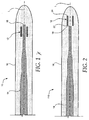
Figure 1 is a cross-sectional view of an embodiment of an elongate guidewire having a marker member encapsulated within an outer sheath; -
Figure 2 is a cross-sectional view of another embodiment of an elongate guidewire having a marker member encapsulated within an outer sheath; -
Figure 3 is a cross-sectional view of another embodiment of an elongate guidewire having multiple marker members encapsulated within an outer sheath; -
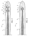
Figure 4 is a cross-sectional view of another embodiment of an elongate guidewire having a marker member encapsulated within an outer sheath; -
Figure 5 is a cross-sectional view of a first sheath layer disposed over an elongate shaft; -
Figure 6 is a cross-sectional view of a marker member disposed over the first sheath layer shown inFigure 5 ; -
Figure 7 is a cross-sectional view of second sheath layer disposed over the marker member, first sheath layer, and shaft shown inFigure 6 ; and -
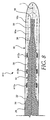
Figure 8 is a cross-sectional view of another embodiment of an elongate guidewire having multiple marker members encapsulated within an outer sheath. - The following description should be read with reference to the drawings wherein like reference numerals indicate like elements throughout the several views. The detailed description and drawings illustrate example embodiments of the claimed invention.
- Many guidewire designs have a radiopaque marker member such as a band or coil attached to a shaft to help a user monitor the location of the guidewire. The invention, in at least some embodiments, includes a guidewire having one or more marker members embedded within an outer sheath. Other embodiments relate to methods of making such guidewires. In at least some embodiments, the embedding of the marker member within the sheath is the sole attachment mechanism for attaching the marker to the guidewire. Some of the features described herein and some of the example embodiments shown in
Figures 1-8 can incorporate or provide desirable properties. For example, in some embodiments, embedding a marker member within the sheath allows the guidewire to have a smooth, lubricious exterior surface and the lubricous exterior surface can allow the guidewire to slide more freely within, for example, a catheter lumen. Other desirable properties of some embodiments may include, but are not limited to, elimination of the need of an adhesive, solder, or braze to attach the marker member to a central shaft; the ability to extend the marker member distally beyond a distal end of the shaft; and the ability to alter the radiopacity and stiffness/flexibility characteristics of the guidewire. -
Figure 1 is a cross-sectional view of an example embodiment of anelongate guidewire 10 having amarker member 12 disposed around the longitudinal axis L of anelongate shaft 14 and encapsulated within anouter sheath 16. For illustration purposes only,Figures 1-7 depict guidewire 10 (and analogous guidewires) as an intravascular guidewire. However, it can be appreciated that in other embodiments,guidewire 10 could also be another type of guidewire, for example, an endoscopic device, an arthroscopic device, and the like. -
Shaft 14 includes a proximal end (not shown), adistal end 18, and can be made of any material suitable including metals, metal alloys, polymers, or the like, or combinations or mixtures thereof. Some examples of suitable metals and metal alloys include stainless steel, such as 304v stainless steel; nickel-titanium alloy, such as nitinol, nickel-chromium alloy, nickel-chromium-iron alloy, cobalt alloy, or the like; or other suitable material. The word nitinol was coined by a group of researchers at the United States Naval Ordinance Laboratory (NOL) who were the first to observe the shape memory behavior of this material. The word nitinol is an acronym including the chemical symbol for nickel (Ni), the chemical symbol for titanium (Ti), and an acronym identifying the Naval Ordinance Laboratory (NOL). - The
entire shaft 14 can be made of the same material, or in some embodiments, can include portions or sections made of different materials. In some embodiments, the material used to constructshaft 14 is chosen to impart varying flexibility and stiffness characteristics to different portions ofshaft 14. For example, a proximal portion and a distal portion ofshaft 14 may be formed of different materials (i.e., materials having different moduli of elasticity) resulting in a difference in flexibility. In some embodiments, the material used to construct the proximal portion can be relatively stiff for pushability and torqueability, and the material used to construct the distal portion can be relatively flexible by comparison for better lateral trackability and steerability. For example, the proximal portion can be formed of straightened 304v stainless steel wire, and the distal portion can be formed of a straightened super elastic or linear elastic alloy (e.g., nickel-titanium) wire. - In embodiments where different portions of
shaft 14 are made of different material, the different portions are connected using any suitable connecting techniques. For example, the different portions of the core wire can be connected using welding, soldering, brazing, adhesive, or the like, or combinations thereof. Additionally, some embodiments can include one or more mechanical connectors or connector assemblies to connect the different portions of the core wire that are made of different materials. The connector may comprise any structure generally suitable for connecting portions of a guidewire. One example of a suitable structure includes a structure such as a hypotube or a coiled wire which has an inside diameter sized appropriately to receive and connect to the ends of the proximal portion and the distal portion. Other examples of suitable techniques and structures that can be used to interconnect different shaft sections are disclosed inU.S. Patent Application No. 09/972,276 , which is incorporated herein by reference. -
Shaft 14 can have a solid cross-section as shown, but in some embodiments, can have a hollow cross-section. In yet other embodiments,shaft 14 can include a combination of areas having solid cross-sections and hollow cross sections.Shaft 14 can be continuously tapered, can have a tapered section or a number or series of tapered sections of differing diameters, or can have a constant diameter. In some embodiments,shaft 14 is tapered or otherwise formed to have a geometry that decreases in cross sectional area towarddistal end 18. If tapered,shaft 14 can include a uniform or a non-uniform transition of the sections, depending on the transition characteristics desired. For example,shaft 14 may be linearly tapered, tapered in a curvilinear fashion, or tapered in a step-wise fashion. The angle of any such tapers can vary, depending upon the desired flexibility characteristics. The length of the taper may be selected to obtain a more (longer length) or less (shorter length) gradual transition in stiffness. -
Shaft 14 may be tapered or shaped by any one of a number of different techniques, for example, by centerless grinding methods. The centerless grinding technique may utilize an indexing system employing sensors (e.g., optical/reflective, magnetic) to avoid excessive grinding of the connection. In addition, the centerless grinding technique may utilize a CBN or diamond abrasive grinding wheel that is well shaped and dressed to avoid grabbingshaft 14 during the grinding process. In some embodiments,shaft 14 is centerless ground using a Royal Master HI-AC centerless grinder. - The length of shaft 14 (or the length of individual portions thereof) are typically dictated by the length and flexibility characteristics desired in the final guidewire. For example,
shaft 14 may include a proximal portion having a length in the range of about 20 to about 300 centimeters and a distal portion having a length in the range of about 3 to about 50 centimeters. It can be appreciated that alterations in the length ofshaft 14 or portions thereof can be altered without departing from the spirit of the invention. -
Marker member 12 is disposed around longitudinal axis L ofshaft 14. Longitudinal axis L ofshaft 14 is understood to be an axis running along the length ofshaft 14. Longitudinal axis L ofshaft 14 is understood to extend beyonddistal end 18 and the proximal end ofshaft 14, following the same general path or direction asshaft 12. The location ofmarker member 12 can be described relative to longitudinal axis L ofshaft 14. For example, describingmarker member 12 as being disposed around longitudinal axis L ofshaft 14 can includemarker member 12 being disposed aroundshaft 14. Additionally, being disposed around longitudinal axis L ofshaft 14 can also includemarker member 12 being disposed at a location distal todistal end 18 ofshaft 14. - In some embodiments,
marker member 12 includes radiopaque materials. Radiopaque materials are understood to be materials capable of producing a relatively bright image on a fluoroscopy screen or another imaging technique during a medical procedure. This relatively bright image aids the user ofguidewire 10 in determining its location. Radiopaque materials can include, but are not limited to, gold, platinum, palladium, tantalum, tungsten alloy, plastic material loaded with a radiopaque filler, and the like. - The structure of
marker member 12 can include any shape or form suitable for encapsulation withinsheath 16. For example, in someembodiments marker member 12 may comprise a tubular, partially tubular, cylindrical (i.e., "C" or "U" shaped), a straight or cupped structure, or other suitably shaped member that is disposed adjacent longitudinal axis L ofshaft 14. Themarker member 12 can have a generally constant diameter configuration, or in some embodiments can be tapered, for example, to correspond with a taper of the core. Such a tapered marker can also provide variable radiopacity in some embodiments. Becausemarker member 12 is embedded withinouter sheath 16, it can be seen thatmarker member 12 is spaced fromshaft 14. In the embodiment ofFigure 1 ,marker member 12 may comprise a generally tubular shaped structure, such as a marker band. - From
Figure 1 , it can be seen thatmarker member 12 need not be directly attached toshaft 14. In some embodiments, this may be desirable because a solder or adhesive joint (or other suitable connection) betweenshaft 14 andmarker member 12 may create a relatively rigid or inflexible zone withinguidewire 10. Moreover, because it is often desirable to place markers (e.g., marker member 12) near the distal end ofguidewire 10, and because it is often desirable for the distal end of such guidewires to be highly flexible, eliminating the need for a solder joint may allow for greater distal flexibility.Figures 2-8 illustrate alterative example embodiments ofguidewire 10, where the location, number, and type ofmarker member 12 is altered. These alternative embodiments are discussed in more detail below. - As stated above,
marker member 12 may be embedded withinsheath 16. By "embedded" it is meant thatmarker member 12 is completely encapsulated, surrounded, or covered on all sides bysheath 16. -
Sheath 16 may be made of, for example, a polymer such as a thermoplastic or thermosetting polymer. For example,sheath 16 may be made of polyurethane, polyether-ester (for example a polyether-ester elastomer such as ARNITEL® available from DSM Engineering Plastics), polyester (for example a polyester elastomer such as HYTREL® available from DuPont), or linear low-density polyethylene (for example REXELL®), and the like, or copolymers or mixtures or combinations thereof. Additionally,sheath 16 may be made of polymers such as polyamide (for example, DURETHAN® available from Bayer or CRISTAMID® available from Elf Atochem), elastomeric polyamides, block polyamide/ethers, polyether block amide (PEBA, for example available under the trade name PEBAX®), silicones, polyethylene, Marlex high-density polyethylene, and the like, or mixtures, combinations, or copolymers thereof, or with any of the other materials listed above. Polyamides, for example, are particularly suitable for providing a relativelyrigid sheath 16. Some other suitable materials for a rigid tubular member include polyetheretherketone (PEEK), polyimide (PI), and polyetherimide (PEI). PEBA, in contrast to the rigid polyamides, is a relatively flexible polymeric material. The use of a polyamide can impart a slightly less rigid durometer than the rigid polyamides and slightly greater than the flexible PEBA material. In some embodiments,sheath 16 may be a single polymer, multiple layers, or a blend of polymers. In someembodiments sheath 16 can include a liquid crystal polymer (LCP) blended with other polymers to enhance torqueability. By employing careful selection of materials and processing techniques, thermoplastic, solvent soluble, and thermosetting variants of these and other materials can be employed to achieve the desired results. In some embodiments the sheath can be relatively clear material while in other embodiments the sheath can be more opaque or colored, depending upon the desired visual characteristics. - Additionally, in some embodiments, a coating, for example a lubricious (e.g., hydrophylic) or other type of coating may be applied over portions or all of
sheath 16, and/or other portions ofguidewire 10. Hydrophobic coatings such as fluoropolymers provide a dry lubricity which improves guidewire handling and device exchanges. Lubricious coatings improve steerability and improve lesion crossing capability. Suitable lubricious polymers are well known in the art and may include hydrophilic polymers such as polyarylene oxides, polyvinylpyrolidones, polyvinylalcohols, hydroxy alkyl cellulosics, algins, saccharides, caprolactones, and the like, and mixtures and combinations thereof. Hydrophilic polymers may be blended among themselves or with formulated amounts of water insoluble compounds (including some polymers) to yield coatings with suitable lubricity, bonding, and solubility. Some other examples of such coatings and materials and methods used to create such coatings can be found inU.S. Patent Nos. 6,139,510 and5,772,609 , which are incorporated herein by reference. In some embodiments, the more distal portion ofguidewire 10 is coated with a hydrophilic polymer as discussed above, and the more proximal portion is coated with a fluoropolymer, such as polytetrafluroethylene (PTFE). -
Figure 2 is a cross-sectional view of an alternative embodiment of aguidewire 110.Guidewire 110 is similar in structure to guidewire 10 shown inFigure 1 , except that the position ofmarker member 12 has been altered relative toshaft 14. As shown inFigure 2 ,marker member 12 includes aproximal end 22 and adistal end 24 andproximal end 22 is positioned distally ofdistal end 18 ofshaft 14. Altering the position ofmarker member 12 relative toshaft 14 may incorporate desirable properties intoguidewire 110. For example, it may be desirable to distallytruncate shaft 12 in order to give guidewire 110 a more flexible distal tip. Becausemarker member 12 can be positioned beyonddistal end 18 ofshaft 14, the distal tip can still easily be imaged (beyonddistal end 18 of shaft 14) by monitoring the location ofmarker member 12. - In general,
marker member 12 is positioned neardistal end 18 ofshaft 14. However, it can be appreciated thatmarker member 12 could be positioned at essentially any position along the length ofguidewire 110. -
Figure 3 is a cross-sectional view of aguidewire 210, which is similar in structure to theguidewire 10 shown inFigure 1 , but illustrates some other positions ofmarker member 12 along longitudinal axis L ofshaft 14. For example,marker member 12 may be positioned such thatproximal end 22 is located proximally ofdistal end 18 ofshaft 14, anddistal end 24 is located distally ofdistal end 18 ofshaft 14. FromFigure 3 it can also be appreciated thatguidewire 210 can also include one or moreadditional marker members 212.Marker member 212 could also be positioned at essentially any position along the length ofguidewire 110. For example,marker member 212 may be positioned so thatdistal end 224 is located proximally ofdistal end 18 ofshaft 14. Alternatively,marker member 212 could be positioned distally of shaft 14 (as shown inFigure 2 ), partially overlapping withdistal end 18 of shaft 14 (similar tomarker member 12 ofFigure 3 ). -
Figure 4 is a cross-sectional view of aguidewire 310.Guidewire 310 is similar in structure to guidewire 10 as shown inFigure 1 , except that themarker member 312 is a coil, for example a tubular coil. In some embodiments,coil 312 includes a radiopaque material, and may be completely made of, partially made of, or plated with a radiopaque material. Thus,marker member 312 may be used to aid a user in monitoring the position ofguidewire 310, for example, within the human body. -
Coil 312 may be arranged or configured in essentially any suitable matter. For example, the number of coils, pitch between windings of the coil, thickness of coil wire, shape of coil wire, and other structural parameters can be altered without departing from the spirit of the invention. Moreover,marker member 312 may be positioned essentially anywhere along longitudinal axis L ofshaft 14, including locations distal ofdistal end 18 ofshaft 14 similar tomarker member 12 inFigure 2 . Thus,marker member 312 may be positioned similar tomarker member 12 inFigures 1, 2 , or3 , for example, or at any other suitable location. - Encapsulation of
coil marker member 312 can provide additional advantages. For example, in some embodiments, the encapsulation ofcoil 312 can reduce or eliminate coil bunching or override, which can cause damage to the coil or wire, or can cause wire lockup, for example, within a catheter. Additionally, the coil geometry and configuration can be varied to provide for variable flexibility and radiopacity characteristics. For example, the diameter of the coil, the pitch of the coil, the thickness of the wire and other like structural aspects of the coil can be varied along the length to provide for variable characteristics. -
Figures 5-7 illustrate an embodiment of a method of manufacturing guidewire 10 (or any of the guidewires described herein).Figure 5 is a cross-sectional view of afirst sheath layer 16a disposed overshaft 14 which has been ground to provide a tapered shape. In some embodiments,sheath layer 16a is a portion ofouter sheath 16 that is disposed overshaft 14.Layer 16a may be disposed overshaft 14 using any one of a number of manufacturing techniques. For example,layer 16a may be disposed overshaft 14 by extrusion, molding, casting, thermal forming, thermal-reforming (such as infrared heat flow or reflow techniques), and other suitable techniques. - After disposing
layer 16a overshaft 14, additional processing may occur. For example,layer 16a may be ground, worked, or finished to give it an appropriate size, diameter, and/or texture. In some embodiments it may be useful forlayer 16a to have a generally smooth exterior surface to allow other objects (e.g., marker member 12) to be tightly attached thereto. Alternatively, it may be beneficial to have some degree of "roughness" or unevenness tolayer 16a. In some embodiments, this may aid in maintaining the marker positions during processing, or may aid in the blending oflayer 16a with other layers. -
Marker member 12 may be disposed overlayer 16a in another manufacturing step as illustrated inFigure 6 . Again, it can be appreciated thatmarker member 12 can be disposed at essentially any location alonglayer 16a as discussed above. Moreover,additional marker members 12 can be disposed alonglayer 16a andmarker member 12 can comprise a band, coil, or other suitable structure as described above. - In some embodiments, it may be desirable, but not essential, to attach or couple the
marker member 12 tolayer 16a using suitable attachment techniques, for example adhesives, thermal bonding, laser bonding, crimping, and the like. In some embodiments, thermal bonding may be advantageous because it may eliminate any need to include adhesives or other attachment mechanisms that could impact the flexibility ofguidewire 10. Alternatively, adhesives (for example, ultraviolet adhesives, thixon, and the like), mechanical attachment, or other attachment techniques could be used. Some examples of suitable adhesives include materials similar to or compatible with the material oflayer 16a. Additional processing or manufacturing steps may then take place wherein themarker member 12 and/orlayer 16a are ground, worked, or finished. - A
second sheath layer 16b can then be disposed overfirst layer 16a andmarker member 12, as shown inFigure 7 .Second layer 16b may be disposed overlayer 16a andmarker member 12 using a suitable technique, for example by extruding, molding, casting, thermal forming, thermal-reforming (e.g., I/R heat flow or reflow), or any other suitable method. In addition, thesecond layer 16b can be worked, ground, finished, and the like to giveguidewire 10 the desired exterior texture and/or shape. Becauselayer 16b may comprise the outermost layer ofguidewire 10, in may be desirable in some embodiments to provide the exterior oflayer 16b with a smooth surface. However, alternative textures may be appropriate in other embodiments. - In some embodiments, manufacturing guidewire 10 may also include the blending or
layer 16b withlayer 16a. This may include thermal processing ofguidewire 10 that can result in partial melting or another suitable physical change oflayers 16a/16b so that the layers flow together or join to form a seamless single layer (i.e., outer sheath 16). According to this embodiment, the boundary betweenlayers 16a/16b would essentially be eliminated and only a single structure,sheath 16, would remain. - It can be appreciated that the blending of
layers layer 16a withlayer 16b may be described as melting together, coupling, reflowing the layers, encapsulating, embedding, and the like. It can also be appreciated that blending oflayers 16a/16b can occur without adding an additional step. For example, manufacturing may take place at a relatively rapid rate so thatlayer 16a is still partially molten or warm whenlayer 16b is disposed overlayer 16a andmarker member 12, such that the two layers blend together without additional manufacturing steps. None-the-less, the result of the blending oflayers 16a/16b is the formation ofsheath 16 as shown inFigure 1-4 and7 . - In some embodiments, when the two layers of material are connected together, a pocket or void can be maintained about the site of the marker member. Some such embodiments can improve flexibility of the structure. For example, if the maker is a coil, the coil can flex feely within the pocket.
- In some embodiments, layers 16a and 16b may be made of the same material (e.g., polyurethane). This may allow the blending of
layers 16a/16b to result in a truly seamless joining to formsheath 16. Alternatively, layers 16a/16b may be made of different, but compatible, materials that also could be essentially seamlessly joined. - In some alterative embodiments, the
layers 16a/16b for example, are not necessarily blending together to form a seamless joint, but rather are maintained in position relative to one another using suitable bonding techniques, for example, adhesives, mechanical bonding, and the like. - In some embodiments, guidewire 10 (or any of the guidewires described herein) may include additional structure or manufacturing steps. For example, guidewire 10 may include a support structure disposed under, within, or around
sheath 16. The support member may comprise a coil, braid, additional polymeric layer, or other structure, and may extend along a portion or the complete length ofguidewire 10. -
Figure 8 is a cross-sectional view of aguidewire 410, which is similar to guidewire 10 as shown inFigure 1 , but illustrates three sets ofmarker members 412a/b/c (shown as coils), and that thesheath 16 may cover only a portion ofshaft 14. It will be understood by those of skill in the art and others that a broad variety of materials, dimensions, and structures can be used to construct suitable embodiments (including all those describe above), depending upon the desired characteristics. The following examples of some dimensions forguidewire 410 are included by way of example only, and are not intended to be limiting. - In some specific embodiments, guidewire 410 has the general structure set fourth in
Figure 8 and may be manufactured according to any of the methods described above.Shaft 14 may also include a firstconstant diameter portion 26, a secondconstant diameter portion 28, and a thirdconstant diameter portion 30. Betweenportion 26 andportion 28 can be a first taperedportion 32, and betweenportion 28 andportion 30 can be a second taperedportion 34. - The lengths of
portions 26/28/30 may be in the range of about 50.8 cm to 381 cm (20 to 150 inches) forportion 26, for example, about 95,25 cm (37.5 inches); about 2,54 to 12,7 cm (1 to 5 inches) forportion 28, for example, about 6,35 cm (2.5 inches); and about 1,27 to 6,35 cm (0.5 to 2.5 inches) forportion 30, for example, about 2,54 cm (1 inch). Theportions 26/28/30 may also have outside diameters in the range of about 0,025 to 0,051 cm (0.01 to about 0.02 inches), for example about 0,033 cm (0.013 inches), forportion 26; about 0,005 to 0,015cm (0.002 to about 0.006 inches), for example about 0,011 cm (0.0044 inches), forportion 28; and about 0,003 to 0,010 cm (0.001 to about 0.004 inches), for example about 0,008 cm (0.003 inches), forportion 30. -
Tapered portions 32/34 may taper at a constant angle, a varying angle, a curvilinear fashion, a stepwise fashion, or in any other suitable manner. First taperedportion 32 may be in the range of about 0,25 to 1,27 cm (0.1 to about 0.5 inches) in length, for example about 0,76 cm (0.3 inches), and second taperedportion 34 may be in the range of about 1,27 cm to about 7,62 cm (0.5 to about 3 inches) in length, for example about 2,54 cm (1 inch). - As shown in
Figure 8 ,marker members 412a/b/c can be disposed around second portion 28 (i.e., overfirst layer 16a). It can be appreciated, however, that marker members 412 could be disposed at essentially any position along longitudinal axis L ofshaft 14 as described above. For example,marker member 412a may be disposed about 5,08 to 12,70 cm (2 to 5 inches), for example about 9,9 cm (3.9 inches), fromdistal end 18 ofshaft 14. Similarly,marker member 412b may be disposed about 3,81 to 11,43 cm (1.5 to 4.5 inches), for example about 8,13 cm (3.2 inches), fromdistal end 18 ofshaft 14, andmarker member 412c may be disposed about 2,54 to 10,16 cm (1 to 4 inches), for example about 6,35 cm (2,5 inches), fromdistal end 18 ofshaft 14. In some examples, the spacing between any two marker members may be in the range of about 1,27 to 3,81 cm (0.5 to 1.5 inches), for example about 1,78 cm (0.7 inches). - In some embodiments, manufacturing guidewire 410 may include disposing
first layer 16a overshaft 14 as shown inFigure 5 . In some embodiments, the outside diameter oflayer 16a may be in the range of about 0,01 to 0,025 cm (0.004 to about 0.010 inches), for example about 0,016 cm (0.0062 inches). Moreover, the outside diameter ofsecond layer 16b (and, therefore, sheath 16) may be in the range of about 0,025 to about 0,051 cm (0.01 to about 0.02 inches), for example about 0,033 cm (0.013 inches). As shown inFigure 8 ,sheath 16 coversfirst taper 32,second portion 28,second taper 34, andthird portion 30 ofshaft 14. In some embodiments, aproximal end 36 ofsheath 16 may extend up tofirst portion 26 ofshaft 14. This will provide a generally constant outside diameter forguidewire 410 fromportion 26 tosheath 16. Thus,sheath 16 can have an outside diameter that is about equal to the outside diameter ofportion 26. - It should be understood that this disclosure is, in many respects, only illustrative. Changes may be made in details, particularly in matters of shape, size, and arrangement of steps without exceeding the scope of the invention. The invention's scope is, of course, defined in the language in which the appended claims are expressed.
Claims (27)
- A guidewire, comprising:an elongate shaft having a proximal end, a distal end, and a longitudinal axis;a polymeric sheath disposed over at least a portion of the shaft;a marker member disposed about at least a portion of the longitudinal axis and having a proximal end and a distal end;
characterized in that the marker member is encapsulated within the sheath and spaced, apart from the shaft. - The guidewire in accordance with claim 1, wherein the shaft is tapered near the distal end.
- The guidewire in accordance with claim 1, wherein the proximal end of the marker member is disposed distally of the distal end of the shaft.
- The guidewire in accordance with claim 1, wherein the distal end of the marker member is disposed proximally of the distal end of the shaft.
- The guidewire in accordance with claim 1, wherein the distal end of the marker member is disposed distally of the distal end of the shaft and the proximal end of the marker member is disposed proximally of the distal end of the shaft.
- The guidewire in accordance with claim 1, wherein the polymeric sheath includes a first layer and a second layer and wherein the marker member is embedded between the first layer and the second layer.
- The guidewire in accordance with claim 6, wherein the first layer and the second layer comprise the same material.
- The guidewire in accordance with claim 6, wherein the first layer and the second layer are integrally joined by a seamless connection.
- The guidewire in accordance with claim 1, wherein the marker member surrounds a portion of the longitudinal axis.
- The guidewire in accordance with claim 1, further comprising a second marker member disposed around the longitudinal axis of the shaft and encapsulated within the sheath.
- The guidewire in accordance with claim 1, wherein the encapsulation of the marker member within the sheath is the sole mechanism by which the marker member is attached to the guidewire.
- The guidewire in accordance with claim 1, wherein the shaft is a core wire.
- The guidewire in accordance with claim 12, wherein the marker member is disposed around a portion of the core wire.
- The guidewire in accordance with claim 12, wherein at least a portion of the marker member is disposed distally of the distal end of the core wire.
- A method of manufacturing a guidewire, comprising:providing an elongate shaft having a proximal end and a distal end;disposing a first polymeric layer over at least a portion of the shaft;
characterized in that the methed comprises:disposing a marker member around at least a portion of the first polymeric layer; anddisposing a second polymeric layer over the first polymeric layer and the marker such that the marker is embedded within the polymeric layers. - The method in accordance with claim 15, wherein at least a portion of the marker member is disposed at a location along the first polymeric layer that is distal of the distal end of the shaft.
- The method in accordance with claim 15, wherein at least a portion of the marker member is disposed at a location along the first polymeric layer that is proximal of the distal end of the shaft.
- The method in accordance with claim 15, wherein the embedding of the marker member within the polymer layers is the sole mechanism by which the marker member is attached to the guidewire.
- The method in accordance with claim 15, wherein the step of disposing a second polymeric layer over the first polymeric layer and the marker includes blending the first polymeric layer and the second polymeric layer to form a seamlessly joined single layer.
- The method in accordance with claim 15, further comprising the step of processing the guidewire so that the first layer and the second layer seamlessly blend to become a single layer.
- The method in accordance with claim 20, wherein the processing step is performed through thermal processing.
- The method in accordance with claim 15, wherein the first layer and the second layer are made of the same polymer.
- The guidewire in accordance with claim 1, wherein the marker member comprises a radiopaque marker band.
- The guidewire in accordance with claim 1, wherein the marker member comprises a radiopaque coil.
- The guidewire in accordance with claim 1, wherein the marker member is a tubular structure.
- The guidewire in accordance with claim 1, wherein the sheath is comprised of polyurethane.
- The guidewire in accordance with claim 1, wherein the marker member is a tubular structure having an interior face and an exterior face, wherein the sheath has a first portion and a second portion, wherein the tubular marker member is encapsulated within the sheath such that the first portion of the sheath is disposed between the interior face of the marker member and the shaft and the second portion of the sheath is disposed near the exterior face of the marker member.
Applications Claiming Priority (3)
| Application Number | Priority Date | Filing Date | Title |
|---|---|---|---|
| US152435 | 2002-05-21 | ||
| US10/152,435 US7022086B2 (en) | 2002-05-21 | 2002-05-21 | Guidewire with encapsulated marker |
| PCT/US2003/013393 WO2003099371A1 (en) | 2002-05-21 | 2003-04-30 | Guidewire with encapsulated marker |
Publications (2)
| Publication Number | Publication Date |
|---|---|
| EP1509274A1 EP1509274A1 (en) | 2005-03-02 |
| EP1509274B1 true EP1509274B1 (en) | 2010-04-28 |
Family
ID=29582063
Family Applications (1)
| Application Number | Title | Priority Date | Filing Date |
|---|---|---|---|
| EP03736513A Expired - Lifetime EP1509274B1 (en) | 2002-05-21 | 2003-04-30 | Guidewire with encapsulated marker |
Country Status (8)
| Country | Link |
|---|---|
| US (1) | US7022086B2 (en) |
| EP (1) | EP1509274B1 (en) |
| JP (1) | JP4384029B2 (en) |
| AT (1) | ATE465770T1 (en) |
| AU (1) | AU2003237133A1 (en) |
| CA (1) | CA2486176C (en) |
| DE (1) | DE60332342D1 (en) |
| WO (1) | WO2003099371A1 (en) |
Families Citing this family (21)
| Publication number | Priority date | Publication date | Assignee | Title |
|---|---|---|---|---|
| US20050246007A1 (en) * | 2004-04-28 | 2005-11-03 | Medtronic, Inc. | Novel lead body assemblies |
| DE102004028367A1 (en) * | 2004-06-11 | 2005-12-29 | Biotronik Vi Patent Ag | Catheter Guidewire especially for cardio-vascular procedures |
| JP2006068497A (en) * | 2004-08-03 | 2006-03-16 | Ist:Kk | Method for manufacturing medical wire and medical wire |
| JP2006320638A (en) * | 2005-05-20 | 2006-11-30 | Ist Corp | Method for manufacturing medical wire |
| US20070179582A1 (en) * | 2006-01-31 | 2007-08-02 | Marshall Mark T | Polymer reinforced coil conductor for torque transmission |
| US8622931B2 (en) | 2007-02-09 | 2014-01-07 | Boston Scientific Scimed, Inc. | Extruded guidewires and methods of making |
| CA2692938C (en) * | 2007-07-11 | 2014-06-17 | Board Of Regents, The University Of Texas System | Seeds and markers for use in imaging |
| US7811623B2 (en) * | 2007-12-21 | 2010-10-12 | Innovatech, Llc | Marked precoated medical device and method of manufacturing same |
| US8231926B2 (en) | 2007-12-21 | 2012-07-31 | Innovatech, Llc | Marked precoated medical device and method of manufacturing same |
| US8048471B2 (en) * | 2007-12-21 | 2011-11-01 | Innovatech, Llc | Marked precoated medical device and method of manufacturing same |
| US7714217B2 (en) * | 2007-12-21 | 2010-05-11 | Innovatech, Llc | Marked precoated strings and method of manufacturing same |
| US8231927B2 (en) | 2007-12-21 | 2012-07-31 | Innovatech, Llc | Marked precoated medical device and method of manufacturing same |
| ATE550065T1 (en) * | 2007-12-28 | 2012-04-15 | Terumo Corp | GUIDE WIRE |
| DE102008006402A1 (en) | 2008-01-28 | 2009-07-30 | Magnamedics Gmbh | Coated instruments for invasive medicine |
| US11298251B2 (en) | 2010-11-17 | 2022-04-12 | Abbott Cardiovascular Systems, Inc. | Radiopaque intraluminal stents comprising cobalt-based alloys with primarily single-phase supersaturated tungsten content |
| BR112013018534B1 (en) | 2011-01-20 | 2021-04-06 | Board Of Regents, The University Of Texas System | CONTRAST AGENT, ITS PREPARATION METHODS, AND COMBINATION PRODUCT |
| JP5382953B2 (en) * | 2011-01-28 | 2014-01-08 | 朝日インテック株式会社 | Guide wire |
| US8900652B1 (en) | 2011-03-14 | 2014-12-02 | Innovatech, Llc | Marked fluoropolymer surfaces and method of manufacturing same |
| US9724494B2 (en) * | 2011-06-29 | 2017-08-08 | Abbott Cardiovascular Systems, Inc. | Guide wire device including a solderable linear elastic nickel-titanium distal end section and methods of preparation therefor |
| EP3016710B1 (en) * | 2013-07-03 | 2020-04-08 | Boston Scientific Scimed, Inc. | Guidewire |
| JP2019129957A (en) * | 2018-01-30 | 2019-08-08 | オリンパス株式会社 | Resin molded product for medical instrument and medical instrument |
Family Cites Families (49)
| Publication number | Priority date | Publication date | Assignee | Title |
|---|---|---|---|---|
| US4657024A (en) | 1980-02-04 | 1987-04-14 | Teleflex Incorporated | Medical-surgical catheter |
| US4571240A (en) | 1983-08-12 | 1986-02-18 | Advanced Cardiovascular Systems, Inc. | Catheter having encapsulated tip marker |
| US4763647A (en) | 1987-01-06 | 1988-08-16 | C. R. Bard, Inc. | Dual coil steerable guidewire |
| US4922924A (en) | 1989-04-27 | 1990-05-08 | C. R. Bard, Inc. | Catheter guidewire with varying radiopacity |
| US5063935A (en) | 1989-04-27 | 1991-11-12 | C. R. Bard, Inc. | Catheter guidewire with varying radiopacity |
| WO1991000051A1 (en) | 1989-06-28 | 1991-01-10 | Boston Scientific Corporation | Steerable highly elongated guidewire |
| JP2540211B2 (en) | 1989-07-10 | 1996-10-02 | テルモ株式会社 | Guide wire |
| US5144959A (en) | 1989-08-15 | 1992-09-08 | C. R. Bard, Inc. | Catheter guidewire with varying radiopacity |
| US5345945A (en) | 1990-08-29 | 1994-09-13 | Baxter International Inc. | Dual coil guidewire with radiopaque distal tip |
| US5174302A (en) | 1990-12-04 | 1992-12-29 | Cordis Corporation | Variable radiopacity guidewire with spaced highly radiopaque regions |
| US5228453A (en) | 1991-05-07 | 1993-07-20 | Target Therapeutics, Inc. | Catheter guide wire |
| US5241970A (en) | 1991-05-17 | 1993-09-07 | Wilson-Cook Medical, Inc. | Papillotome/sphincterotome procedures and a wire guide specially |
| US5443907A (en) | 1991-06-18 | 1995-08-22 | Scimed Life Systems, Inc. | Coating for medical insertion guides |
| CA2068584C (en) | 1991-06-18 | 1997-04-22 | Paul H. Burmeister | Intravascular guide wire and method for manufacture thereof |
| US5213111A (en) | 1991-07-10 | 1993-05-25 | Cook Incorporated | Composite wire guide construction |
| US5333620A (en) | 1991-10-30 | 1994-08-02 | C. R. Bard, Inc. | High performance plastic coated medical guidewire |
| US5253653A (en) | 1991-10-31 | 1993-10-19 | Boston Scientific Corp. | Fluoroscopically viewable guidewire for catheters |
| US5353808A (en) | 1992-03-04 | 1994-10-11 | Cordis Corporation | Guidewire having distally located marker segment |
| US5368048A (en) | 1993-04-19 | 1994-11-29 | Stoy; George P. | Method of making radio-opaque tipped, sleeved guidewire and product |
| US5409015A (en) | 1993-05-11 | 1995-04-25 | Target Therapeutics, Inc. | Deformable tip super elastic guidewire |
| US5772609A (en) | 1993-05-11 | 1998-06-30 | Target Therapeutics, Inc. | Guidewire with variable flexibility due to polymeric coatings |
| EP0712354B1 (en) * | 1993-08-06 | 1999-01-13 | Minnesota Mining And Manufacturing Company | Multilayered tubing |
| US6673025B1 (en) * | 1993-12-01 | 2004-01-06 | Advanced Cardiovascular Systems, Inc. | Polymer coated guidewire |
| JPH0737199U (en) | 1993-12-24 | 1995-07-11 | テルモ株式会社 | Guide wire |
| US5606981A (en) | 1994-03-11 | 1997-03-04 | C. R. Bard, Inc. | Catheter guidewire with radiopaque markers |
| JP3698449B2 (en) * | 1994-04-07 | 2005-09-21 | 株式会社パイオラックス | Guide wire and manufacturing method thereof |
| US5817017A (en) | 1994-04-12 | 1998-10-06 | Pharmacyclics, Inc. | Medical devices and materials having enhanced magnetic images visibility |
| US6139510A (en) | 1994-05-11 | 2000-10-31 | Target Therapeutics Inc. | Super elastic alloy guidewire |
| US5916178A (en) | 1995-03-30 | 1999-06-29 | Medtronic, Inc. | Steerable high support guidewire with thin wall nitinol tube |
| JPH0994298A (en) | 1995-09-28 | 1997-04-08 | Terumo Corp | Guide wire |
| US6027461A (en) | 1995-10-11 | 2000-02-22 | Micro Therapeutics, Inc. | Infusion guidewire having fixed core wire and flexible radiopaque marker |
| US5997487A (en) | 1995-10-11 | 1999-12-07 | Micro Therapeutics, Inc. | Infusion wire having fixed core wire |
| US5836892A (en) | 1995-10-30 | 1998-11-17 | Cordis Corporation | Guidewire with radiopaque markers |
| US5836893A (en) | 1996-03-08 | 1998-11-17 | Scimed Life Systems, Inc. | Intravascular guidewire |
| US5833631A (en) | 1996-06-28 | 1998-11-10 | Target Therapeutics, Inc. | Fiber tip guidewire |
| US5993424A (en) | 1996-08-05 | 1999-11-30 | Cordis Corporation | Guidewire having a distal tip that can change its shape within a vessel |
| US6251086B1 (en) | 1999-07-27 | 2001-06-26 | Scimed Life Systems, Inc. | Guide wire with hydrophilically coated tip |
| EP0868925B1 (en) | 1997-03-31 | 2008-04-30 | Terumo Kabushiki Kaisha | Guide wire |
| US5876356A (en) | 1997-04-02 | 1999-03-02 | Cordis Corporation | Superelastic guidewire with a shapeable tip |
| EP0879616A1 (en) | 1997-05-21 | 1998-11-25 | Schneider (Europe) GmbH | Guide wire |
| US6183420B1 (en) | 1997-06-20 | 2001-02-06 | Medtronic Ave, Inc. | Variable stiffness angioplasty guide wire |
| US6306105B1 (en) | 1998-05-14 | 2001-10-23 | Scimed Life Systems, Inc. | High performance coil wire |
| US6402706B2 (en) * | 1998-12-30 | 2002-06-11 | Advanced Cardiovascular Systems, Inc. | Guide wire with multiple polymer jackets over distal and intermediate core sections |
| US6171295B1 (en) | 1999-01-20 | 2001-01-09 | Scimed Life Systems, Inc. | Intravascular catheter with composite reinforcement |
| EP1289411A4 (en) | 2000-06-12 | 2006-03-29 | Cordis Corp | Vascular guidewire for magnetic resonance and/or fluoroscopy |
| US6620114B2 (en) | 2000-10-05 | 2003-09-16 | Scimed Life Systems, Inc. | Guidewire having a marker segment for length assessment |
| US6636758B2 (en) * | 2001-05-01 | 2003-10-21 | Concentric Medical, Inc. | Marker wire and process for using it |
| US6918882B2 (en) * | 2001-10-05 | 2005-07-19 | Scimed Life Systems, Inc. | Guidewire with stiffness blending connection |
| EP1450877A2 (en) * | 2001-11-05 | 2004-09-01 | Memry Corporation | Work-hardened pseudoelastic guide wires |
-
2002
- 2002-05-21 US US10/152,435 patent/US7022086B2/en not_active Expired - Fee Related
-
2003
- 2003-04-30 JP JP2004506894A patent/JP4384029B2/en not_active Expired - Fee Related
- 2003-04-30 EP EP03736513A patent/EP1509274B1/en not_active Expired - Lifetime
- 2003-04-30 DE DE60332342T patent/DE60332342D1/en not_active Expired - Lifetime
- 2003-04-30 CA CA2486176A patent/CA2486176C/en not_active Expired - Fee Related
- 2003-04-30 AT AT03736513T patent/ATE465770T1/en not_active IP Right Cessation
- 2003-04-30 WO PCT/US2003/013393 patent/WO2003099371A1/en active Application Filing
- 2003-04-30 AU AU2003237133A patent/AU2003237133A1/en not_active Abandoned
Also Published As
| Publication number | Publication date |
|---|---|
| US20040225231A1 (en) | 2004-11-11 |
| EP1509274A1 (en) | 2005-03-02 |
| WO2003099371A1 (en) | 2003-12-04 |
| AU2003237133A1 (en) | 2003-12-12 |
| US7022086B2 (en) | 2006-04-04 |
| JP4384029B2 (en) | 2009-12-16 |
| DE60332342D1 (en) | 2010-06-10 |
| CA2486176A1 (en) | 2003-12-04 |
| CA2486176C (en) | 2012-02-21 |
| ATE465770T1 (en) | 2010-05-15 |
| JP2005525916A (en) | 2005-09-02 |
Similar Documents
| Publication | Publication Date | Title |
|---|---|---|
| EP1509274B1 (en) | Guidewire with encapsulated marker | |
| EP1699516B1 (en) | Medical device with push force limiter | |
| US7914467B2 (en) | Tubular member having tapered transition for use in a medical device | |
| US8551020B2 (en) | Crossing guidewire | |
| US8419658B2 (en) | Medical device including structure for crossing an occlusion in a vessel | |
| US9375234B2 (en) | Medical device including structure for crossing an occlusion in a vessel | |
| EP1667757B1 (en) | Medical device coil | |
| US8022331B2 (en) | Method of making elongated medical devices | |
| EP1663370B1 (en) | Medical device coil | |
| EP2068994B1 (en) | Catheter shaft including a metallic tapered region | |
| US20040064069A1 (en) | Medical device with support member | |
| US20090292225A1 (en) | Medical device including a braid for crossing an occlusion in a vessel | |
| US20080045908A1 (en) | Medical device including a metallic tube fillet welded to a core member | |
| US20040167438A1 (en) | Reinforced medical device | |
| WO2005007033A1 (en) | Embolic protection filtering device |
Legal Events
| Date | Code | Title | Description |
|---|---|---|---|
| PUAI | Public reference made under article 153(3) epc to a published international application that has entered the european phase |
Free format text: ORIGINAL CODE: 0009012 |
|
| 17P | Request for examination filed |
Effective date: 20041216 |
|
| AK | Designated contracting states |
Kind code of ref document: A1 Designated state(s): AT BE BG CH CY CZ DE DK EE ES FI FR GB GR HU IE IT LI LU MC NL PT RO SE SI SK TR |
|
| AX | Request for extension of the european patent |
Extension state: AL LT LV MK |
|
| DAX | Request for extension of the european patent (deleted) | ||
| 17Q | First examination report despatched |
Effective date: 20071108 |
|
| GRAP | Despatch of communication of intention to grant a patent |
Free format text: ORIGINAL CODE: EPIDOSNIGR1 |
|
| GRAS | Grant fee paid |
Free format text: ORIGINAL CODE: EPIDOSNIGR3 |
|
| GRAA | (expected) grant |
Free format text: ORIGINAL CODE: 0009210 |
|
| AK | Designated contracting states |
Kind code of ref document: B1 Designated state(s): AT BE BG CH CY CZ DE DK EE ES FI FR GB GR HU IE IT LI LU MC NL PT RO SE SI SK TR |
|
| REG | Reference to a national code |
Ref country code: GB Ref legal event code: FG4D |
|
| REG | Reference to a national code |
Ref country code: CH Ref legal event code: EP |
|
| REG | Reference to a national code |
Ref country code: IE Ref legal event code: FG4D |
|
| REG | Reference to a national code |
Ref country code: NL Ref legal event code: T3 |
|
| REF | Corresponds to: |
Ref document number: 60332342 Country of ref document: DE Date of ref document: 20100610 Kind code of ref document: P |
|
| PG25 | Lapsed in a contracting state [announced via postgrant information from national office to epo] |
Ref country code: SE Free format text: LAPSE BECAUSE OF FAILURE TO SUBMIT A TRANSLATION OF THE DESCRIPTION OR TO PAY THE FEE WITHIN THE PRESCRIBED TIME-LIMIT Effective date: 20100428 Ref country code: ES Free format text: LAPSE BECAUSE OF FAILURE TO SUBMIT A TRANSLATION OF THE DESCRIPTION OR TO PAY THE FEE WITHIN THE PRESCRIBED TIME-LIMIT Effective date: 20100808 |
|
| PG25 | Lapsed in a contracting state [announced via postgrant information from national office to epo] |
Ref country code: FI Free format text: LAPSE BECAUSE OF FAILURE TO SUBMIT A TRANSLATION OF THE DESCRIPTION OR TO PAY THE FEE WITHIN THE PRESCRIBED TIME-LIMIT Effective date: 20100428 Ref country code: AT Free format text: LAPSE BECAUSE OF FAILURE TO SUBMIT A TRANSLATION OF THE DESCRIPTION OR TO PAY THE FEE WITHIN THE PRESCRIBED TIME-LIMIT Effective date: 20100428 Ref country code: SI Free format text: LAPSE BECAUSE OF FAILURE TO SUBMIT A TRANSLATION OF THE DESCRIPTION OR TO PAY THE FEE WITHIN THE PRESCRIBED TIME-LIMIT Effective date: 20100428 Ref country code: MC Free format text: LAPSE BECAUSE OF NON-PAYMENT OF DUE FEES Effective date: 20100430 |
|
| REG | Reference to a national code |
Ref country code: CH Ref legal event code: PL |
|
| PG25 | Lapsed in a contracting state [announced via postgrant information from national office to epo] |
Ref country code: CY Free format text: LAPSE BECAUSE OF FAILURE TO SUBMIT A TRANSLATION OF THE DESCRIPTION OR TO PAY THE FEE WITHIN THE PRESCRIBED TIME-LIMIT Effective date: 20100428 Ref country code: GR Free format text: LAPSE BECAUSE OF FAILURE TO SUBMIT A TRANSLATION OF THE DESCRIPTION OR TO PAY THE FEE WITHIN THE PRESCRIBED TIME-LIMIT Effective date: 20100729 |
|
| PG25 | Lapsed in a contracting state [announced via postgrant information from national office to epo] |
Ref country code: DK Free format text: LAPSE BECAUSE OF FAILURE TO SUBMIT A TRANSLATION OF THE DESCRIPTION OR TO PAY THE FEE WITHIN THE PRESCRIBED TIME-LIMIT Effective date: 20100428 Ref country code: EE Free format text: LAPSE BECAUSE OF FAILURE TO SUBMIT A TRANSLATION OF THE DESCRIPTION OR TO PAY THE FEE WITHIN THE PRESCRIBED TIME-LIMIT Effective date: 20100428 Ref country code: PT Free format text: LAPSE BECAUSE OF FAILURE TO SUBMIT A TRANSLATION OF THE DESCRIPTION OR TO PAY THE FEE WITHIN THE PRESCRIBED TIME-LIMIT Effective date: 20100830 |
|
| PG25 | Lapsed in a contracting state [announced via postgrant information from national office to epo] |
Ref country code: CZ Free format text: LAPSE BECAUSE OF FAILURE TO SUBMIT A TRANSLATION OF THE DESCRIPTION OR TO PAY THE FEE WITHIN THE PRESCRIBED TIME-LIMIT Effective date: 20100428 Ref country code: BE Free format text: LAPSE BECAUSE OF FAILURE TO SUBMIT A TRANSLATION OF THE DESCRIPTION OR TO PAY THE FEE WITHIN THE PRESCRIBED TIME-LIMIT Effective date: 20100428 Ref country code: CH Free format text: LAPSE BECAUSE OF NON-PAYMENT OF DUE FEES Effective date: 20100430 Ref country code: LI Free format text: LAPSE BECAUSE OF NON-PAYMENT OF DUE FEES Effective date: 20100430 Ref country code: RO Free format text: LAPSE BECAUSE OF FAILURE TO SUBMIT A TRANSLATION OF THE DESCRIPTION OR TO PAY THE FEE WITHIN THE PRESCRIBED TIME-LIMIT Effective date: 20100428 Ref country code: SK Free format text: LAPSE BECAUSE OF FAILURE TO SUBMIT A TRANSLATION OF THE DESCRIPTION OR TO PAY THE FEE WITHIN THE PRESCRIBED TIME-LIMIT Effective date: 20100428 |
|
| PLBE | No opposition filed within time limit |
Free format text: ORIGINAL CODE: 0009261 |
|
| STAA | Information on the status of an ep patent application or granted ep patent |
Free format text: STATUS: NO OPPOSITION FILED WITHIN TIME LIMIT |
|
| 26N | No opposition filed |
Effective date: 20110131 |
|
| PG25 | Lapsed in a contracting state [announced via postgrant information from national office to epo] |
Ref country code: BG Free format text: LAPSE BECAUSE OF FAILURE TO SUBMIT A TRANSLATION OF THE DESCRIPTION OR TO PAY THE FEE WITHIN THE PRESCRIBED TIME-LIMIT Effective date: 20100428 Ref country code: LU Free format text: LAPSE BECAUSE OF NON-PAYMENT OF DUE FEES Effective date: 20100430 Ref country code: HU Free format text: LAPSE BECAUSE OF FAILURE TO SUBMIT A TRANSLATION OF THE DESCRIPTION OR TO PAY THE FEE WITHIN THE PRESCRIBED TIME-LIMIT Effective date: 20101029 |
|
| PG25 | Lapsed in a contracting state [announced via postgrant information from national office to epo] |
Ref country code: TR Free format text: LAPSE BECAUSE OF FAILURE TO SUBMIT A TRANSLATION OF THE DESCRIPTION OR TO PAY THE FEE WITHIN THE PRESCRIBED TIME-LIMIT Effective date: 20100428 |
|
| PG25 | Lapsed in a contracting state [announced via postgrant information from national office to epo] |
Ref country code: BG Free format text: LAPSE BECAUSE OF FAILURE TO SUBMIT A TRANSLATION OF THE DESCRIPTION OR TO PAY THE FEE WITHIN THE PRESCRIBED TIME-LIMIT Effective date: 20100728 |
|
| PGFP | Annual fee paid to national office [announced via postgrant information from national office to epo] |
Ref country code: GB Payment date: 20140430 Year of fee payment: 12 |
|
| PGFP | Annual fee paid to national office [announced via postgrant information from national office to epo] |
Ref country code: FR Payment date: 20140409 Year of fee payment: 12 |
|
| REG | Reference to a national code |
Ref country code: DE Ref legal event code: R082 Ref document number: 60332342 Country of ref document: DE Representative=s name: VOSSIUS & PARTNER PATENTANWAELTE RECHTSANWAELT, DE |
|
| REG | Reference to a national code |
Ref country code: DE Ref legal event code: R082 Ref document number: 60332342 Country of ref document: DE Representative=s name: VOSSIUS & PARTNER PATENTANWAELTE RECHTSANWAELT, DE Effective date: 20150202 Ref country code: DE Ref legal event code: R081 Ref document number: 60332342 Country of ref document: DE Owner name: BOSTON SCIENTIFIC LIMITED, BM Free format text: FORMER OWNER: BOSTON SCIENTIFIC LTD., ST. MICHAEL, BARBADOS, BB Effective date: 20150202 |
|
| GBPC | Gb: european patent ceased through non-payment of renewal fee |
Effective date: 20150430 |
|
| PG25 | Lapsed in a contracting state [announced via postgrant information from national office to epo] |
Ref country code: GB Free format text: LAPSE BECAUSE OF NON-PAYMENT OF DUE FEES Effective date: 20150430 |
|
| REG | Reference to a national code |
Ref country code: FR Ref legal event code: ST Effective date: 20151231 |
|
| PG25 | Lapsed in a contracting state [announced via postgrant information from national office to epo] |
Ref country code: FR Free format text: LAPSE BECAUSE OF NON-PAYMENT OF DUE FEES Effective date: 20150430 |
|
| PGFP | Annual fee paid to national office [announced via postgrant information from national office to epo] |
Ref country code: NL Payment date: 20160411 Year of fee payment: 14 |
|
| PGFP | Annual fee paid to national office [announced via postgrant information from national office to epo] |
Ref country code: IE Payment date: 20160411 Year of fee payment: 14 Ref country code: DE Payment date: 20160426 Year of fee payment: 14 |
|
| PGFP | Annual fee paid to national office [announced via postgrant information from national office to epo] |
Ref country code: IT Payment date: 20160418 Year of fee payment: 14 |
|
| REG | Reference to a national code |
Ref country code: DE Ref legal event code: R119 Ref document number: 60332342 Country of ref document: DE |
|
| REG | Reference to a national code |
Ref country code: NL Ref legal event code: MM Effective date: 20170501 |
|
| REG | Reference to a national code |
Ref country code: IE Ref legal event code: MM4A |
|
| PG25 | Lapsed in a contracting state [announced via postgrant information from national office to epo] |
Ref country code: NL Free format text: LAPSE BECAUSE OF NON-PAYMENT OF DUE FEES Effective date: 20170501 Ref country code: DE Free format text: LAPSE BECAUSE OF NON-PAYMENT OF DUE FEES Effective date: 20171103 |
|
| PG25 | Lapsed in a contracting state [announced via postgrant information from national office to epo] |
Ref country code: IE Free format text: LAPSE BECAUSE OF NON-PAYMENT OF DUE FEES Effective date: 20170430 |
|
| PG25 | Lapsed in a contracting state [announced via postgrant information from national office to epo] |
Ref country code: IT Free format text: LAPSE BECAUSE OF NON-PAYMENT OF DUE FEES Effective date: 20170430 |