EP1510283A1 - Automated adaptive machining of obstructed passages - Google Patents
Automated adaptive machining of obstructed passages Download PDFInfo
- Publication number
- EP1510283A1 EP1510283A1 EP03103232A EP03103232A EP1510283A1 EP 1510283 A1 EP1510283 A1 EP 1510283A1 EP 03103232 A EP03103232 A EP 03103232A EP 03103232 A EP03103232 A EP 03103232A EP 1510283 A1 EP1510283 A1 EP 1510283A1
- Authority
- EP
- European Patent Office
- Prior art keywords
- passage
- machining
- article
- obstructed
- cooling
- Prior art date
- Legal status (The legal status is an assumption and is not a legal conclusion. Google has not performed a legal analysis and makes no representation as to the accuracy of the status listed.)
- Granted
Links
Images

Classifications
-
- B—PERFORMING OPERATIONS; TRANSPORTING
- B23—MACHINE TOOLS; METAL-WORKING NOT OTHERWISE PROVIDED FOR
- B23K—SOLDERING OR UNSOLDERING; WELDING; CLADDING OR PLATING BY SOLDERING OR WELDING; CUTTING BY APPLYING HEAT LOCALLY, e.g. FLAME CUTTING; WORKING BY LASER BEAM
- B23K26/00—Working by laser beam, e.g. welding, cutting or boring
- B23K26/02—Positioning or observing the workpiece, e.g. with respect to the point of impact; Aligning, aiming or focusing the laser beam
- B23K26/04—Automatically aligning, aiming or focusing the laser beam, e.g. using the back-scattered light
-
- B—PERFORMING OPERATIONS; TRANSPORTING
- B23—MACHINE TOOLS; METAL-WORKING NOT OTHERWISE PROVIDED FOR
- B23K—SOLDERING OR UNSOLDERING; WELDING; CLADDING OR PLATING BY SOLDERING OR WELDING; CUTTING BY APPLYING HEAT LOCALLY, e.g. FLAME CUTTING; WORKING BY LASER BEAM
- B23K26/00—Working by laser beam, e.g. welding, cutting or boring
- B23K26/36—Removing material
- B23K26/38—Removing material by boring or cutting
- B23K26/382—Removing material by boring or cutting by boring
- B23K26/389—Removing material by boring or cutting by boring of fluid openings, e.g. nozzles, jets
-
- B—PERFORMING OPERATIONS; TRANSPORTING
- B23—MACHINE TOOLS; METAL-WORKING NOT OTHERWISE PROVIDED FOR
- B23K—SOLDERING OR UNSOLDERING; WELDING; CLADDING OR PLATING BY SOLDERING OR WELDING; CUTTING BY APPLYING HEAT LOCALLY, e.g. FLAME CUTTING; WORKING BY LASER BEAM
- B23K26/00—Working by laser beam, e.g. welding, cutting or boring
- B23K26/36—Removing material
- B23K26/40—Removing material taking account of the properties of the material involved
-
- F—MECHANICAL ENGINEERING; LIGHTING; HEATING; WEAPONS; BLASTING
- F01—MACHINES OR ENGINES IN GENERAL; ENGINE PLANTS IN GENERAL; STEAM ENGINES
- F01D—NON-POSITIVE DISPLACEMENT MACHINES OR ENGINES, e.g. STEAM TURBINES
- F01D5/00—Blades; Blade-carrying members; Heating, heat-insulating, cooling or antivibration means on the blades or the members
- F01D5/005—Repairing methods or devices
-
- F—MECHANICAL ENGINEERING; LIGHTING; HEATING; WEAPONS; BLASTING
- F01—MACHINES OR ENGINES IN GENERAL; ENGINE PLANTS IN GENERAL; STEAM ENGINES
- F01D—NON-POSITIVE DISPLACEMENT MACHINES OR ENGINES, e.g. STEAM TURBINES
- F01D5/00—Blades; Blade-carrying members; Heating, heat-insulating, cooling or antivibration means on the blades or the members
- F01D5/12—Blades
- F01D5/14—Form or construction
- F01D5/18—Hollow blades, i.e. blades with cooling or heating channels or cavities; Heating, heat-insulating or cooling means on blades
- F01D5/186—Film cooling
-
- B—PERFORMING OPERATIONS; TRANSPORTING
- B23—MACHINE TOOLS; METAL-WORKING NOT OTHERWISE PROVIDED FOR
- B23K—SOLDERING OR UNSOLDERING; WELDING; CLADDING OR PLATING BY SOLDERING OR WELDING; CUTTING BY APPLYING HEAT LOCALLY, e.g. FLAME CUTTING; WORKING BY LASER BEAM
- B23K2101/00—Articles made by soldering, welding or cutting
- B23K2101/001—Turbines
-
- B—PERFORMING OPERATIONS; TRANSPORTING
- B23—MACHINE TOOLS; METAL-WORKING NOT OTHERWISE PROVIDED FOR
- B23K—SOLDERING OR UNSOLDERING; WELDING; CLADDING OR PLATING BY SOLDERING OR WELDING; CUTTING BY APPLYING HEAT LOCALLY, e.g. FLAME CUTTING; WORKING BY LASER BEAM
- B23K2101/00—Articles made by soldering, welding or cutting
- B23K2101/34—Coated articles, e.g. plated or painted; Surface treated articles
-
- B—PERFORMING OPERATIONS; TRANSPORTING
- B23—MACHINE TOOLS; METAL-WORKING NOT OTHERWISE PROVIDED FOR
- B23K—SOLDERING OR UNSOLDERING; WELDING; CLADDING OR PLATING BY SOLDERING OR WELDING; CUTTING BY APPLYING HEAT LOCALLY, e.g. FLAME CUTTING; WORKING BY LASER BEAM
- B23K2103/00—Materials to be soldered, welded or cut
- B23K2103/08—Non-ferrous metals or alloys
-
- B—PERFORMING OPERATIONS; TRANSPORTING
- B23—MACHINE TOOLS; METAL-WORKING NOT OTHERWISE PROVIDED FOR
- B23K—SOLDERING OR UNSOLDERING; WELDING; CLADDING OR PLATING BY SOLDERING OR WELDING; CUTTING BY APPLYING HEAT LOCALLY, e.g. FLAME CUTTING; WORKING BY LASER BEAM
- B23K2103/00—Materials to be soldered, welded or cut
- B23K2103/18—Dissimilar materials
- B23K2103/26—Alloys of Nickel and Cobalt and Chromium
-
- B—PERFORMING OPERATIONS; TRANSPORTING
- B23—MACHINE TOOLS; METAL-WORKING NOT OTHERWISE PROVIDED FOR
- B23K—SOLDERING OR UNSOLDERING; WELDING; CLADDING OR PLATING BY SOLDERING OR WELDING; CUTTING BY APPLYING HEAT LOCALLY, e.g. FLAME CUTTING; WORKING BY LASER BEAM
- B23K2103/00—Materials to be soldered, welded or cut
- B23K2103/50—Inorganic material, e.g. metals, not provided for in B23K2103/02 – B23K2103/26
- B23K2103/52—Ceramics
-
- B—PERFORMING OPERATIONS; TRANSPORTING
- B23—MACHINE TOOLS; METAL-WORKING NOT OTHERWISE PROVIDED FOR
- B23P—METAL-WORKING NOT OTHERWISE PROVIDED FOR; COMBINED OPERATIONS; UNIVERSAL MACHINE TOOLS
- B23P2700/00—Indexing scheme relating to the articles being treated, e.g. manufactured, repaired, assembled, connected or other operations covered in the subgroups
- B23P2700/06—Cooling passages of turbine components, e.g. unblocking or preventing blocking of cooling passages of turbine components
-
- G—PHYSICS
- G05—CONTROLLING; REGULATING
- G05B—CONTROL OR REGULATING SYSTEMS IN GENERAL; FUNCTIONAL ELEMENTS OF SUCH SYSTEMS; MONITORING OR TESTING ARRANGEMENTS FOR SUCH SYSTEMS OR ELEMENTS
- G05B2219/00—Program-control systems
- G05B2219/30—Nc systems
- G05B2219/45—Nc applications
- G05B2219/45147—Machining blade, airfoil
Definitions
- the invention relates to an automated machining process for machining of an obstructed passage of an article according to the step of the independent claim.
- cooling channel configurations with a diffuser outlet which has typically a fan shape geometry.
- the diameter of the cylindrical section of the cooling channel defines the total airflow volume, whereas the fan shaped end of the channel results in an advantageous redistribution of the cooling air over the adjacent surface. According to the cooling requirements this film cooling effect can be adjusted by design variations of diffuser outlet.
- cooling holes per component can be as high as several hundreds.
- the geometry of the cooling passages depends on their location on the component. It is not unusual that more than 20 different types of cooling holes can be found on a single component.
- a typical manufacturing sequence of such a part starts with the casting. After the following machining a first metallic protection coating (usually of the MCrAIY family, where M is Ni and/or Co) is sprayed onto the component. A second, ceramic thermal barrier coating (TBC) is then deposited on the first coating. For most gas turbine components the thickness of either coating is in the range from 100 ⁇ m to 600 ⁇ m.
- Cooling holes are only machined after both coatings have been deposited.
- the use of high power, pulsed lasers is common for this purpose.
- an initial start hole is created by percussion drilling, followed by a trepanning step that machines the precise contour of the cooling passage. This process is usually fully automated using expensive 5-axis CNC workcells equipped with a powerful Nd-YAG laser.
- the masking material has to be applied in a time consuming manual process, e.g. with a syringe.
- a suitable etching or heat treatment can subsequently remove the masking material.
- these masking materials do normally not withstand the high temperatures that occur during the plasma deposition of the MCrAIY coating layer, where preheating temperatures exceed 700°C followed by diffusion bonding heat treatment where temperatures rise above 1000°C. This is also the case for the fugitive plug approach as disclosed in US-A-4,743,462 where the plug is made from plastic material that volatises at a temperature below that of the deposition process.
- US-B1-6,172,331 and US-A-6,054,673 give a suitable example of a solid state laser, which is capable to drill both metallic and ceramic material.
- a Nd-YAG laser is used in the q-switch mode, where short pulses of less than 500ns duration are generated.
- the peak pulse power is high enough to remove the material mostly as vapour instead of melt ejection which common for conventional drilling.
- the energy per laser pulse is small and it is thus possible to detect hole breakthrough with a suitable device before significant damage to the wall behind the cooling hole occurs.
- Such an automated method is suggested in US-B1-6,380,512 where a laser drilling process is disclosed to remove coating material from (partially) blocked cooling passages.
- the method relies on a 5-axes CNC workcell and a CNC component program with pre-programmed locations of the cooling holes.
- the drilling apparatus is equipped with a vision system and can thus compensate for component deformation or deviation from blueprint dimensions.
- the vision equipment is used to determine the actual location of the cooling holes either on the coated component or in a condition where the component is being prepared for coating.
- the apparatus is equipped with a flash lamp pumped Nd-YAG laser and the vision system is either mounted to the laser such that an image is obtained through the laser lens or it is separated from the laser.
- the object of the present invention is to provide a advanced method for a more advanced and powerful automated, adaptive machining method allowing to remove residual material from obstructed cooling passages.
- the process according to the present invention is divided into a first step which comprises the detection of the obstructed passages and a second step which comprises a machining step for the removal of obstructing material, which can be carried out on the same or on separate workcells.
- a local reference co-ordinate system is created which uses characteristic features of the article such as corners or grooves.
- An automated scanning vision system is used to obtain actual 3D information of the position and orientations of the cooling passage. This detection process is fully automated and does not require the assistance of an operator.
- the position and orientation of the cooling passage are established with respect to a local reference co-ordinate system which can precisely re-established at a later date. In this way, it is possible to make use of stored hole position and orientation data after intermediate machining steps such as re-coating.
- the hole position and orientation data is saved in a file that contains a unique identifier for the article.
- the data contained in this file is used for a precision machining operation, where residual material from a re-coating operation is removed from the cooling holes.
- a desired cooling flow rate and a favorable film distribution of the cooling medium can be re-established.
- Unwanted material could be overspray coating, other material plugging the cooling passages, recast from the original drilling or base material, if the intention is to enlarge a diffuser-end portion of the cooling passage.
- This is valid for a cooling passage of a turbine component which has a part with cylindrical cross section ending in a diffusor opening. Then, the part with the cylindrical section defines the total amount of cooling fluid that can be guided through the passage.
- the position of each passage is a reference point that is obtained from the intersection of the channel axis with a local tangential surface plane.
- the local tangential plane can be established with any suitable measurement device, e.g. touch probes, eddy current sensors, optical triangulation sensors, conoscopic sensors, interferometers.
- the precision machining operation is either carried out on a dedicated machining workcell (CNC or robotic system) or on the same workcell that was originally used to acquire hole position and orientation data.
- CNC machining workcell
- a high power q-switched or precision drilling solid state laser or waterjet drilling is used for the precision machining operation, e.g. the removal of the unwanted material that prevents the desired flow of the cooling medium.
- Fig. 1 shows an article 1 such as blades or vanes of gas turbine engines, the gas turbine blade comprising a root portion 2, a platform 3 and a blade 4 and cooling holes 5.
- a MCrAIY-coating and/or a thermal barrier coating 6 is applied on the external surface 7 .
- the component can be made from a Nickel base superalloy known in the state of the art, e.g. from the documents US-A-5,888,451, US-A-5,759,301 or from US-A-4,643,782, which is known as "CMSX-4".
- the process according to the present invention is divided into a first step which comprises the detection of the cooling passages 5 and a second step which comprises a machining step, which can be carried out on the same or on separate workcells.
- a local reference co-ordinate system After mounting the component in a fixture in the detection/vision workcell, a local reference co-ordinate system is established. It is important to note that characteristic features of the component itself are used for establishing this reference co-ordinate system. The characteristic features are chosen such that subsequent machining steps do not affect them. Example features are machined side surfaces, corners and rims, or sealing groves. Using such fixed features for the determination of the local co-ordinate system, the component can be later put into another workcell, where it is possible to re-establish the same co-ordinate system. All hole locations and hole orientations are saved with respect to this local reference co-ordinate system. This is an important advantage as the local hole co-ordinates can be reused at any time without tedious alignment of the part.
- the local co-ordinates can be used for the re-opening of cooling holes 5 after the deposition of new protective coatings 6 with thermal spray process.
- No sophisticated fixtures are required, as mounting misfit has no influence on the local co-ordinate system and on the local hole co-ordinates.
- the workcell for the detection of cooling holes 5 is based on a robot equipped with a vision system and an optical sensor.
- absolute accuracy calibration techniques can be applied prior to the use of this system.
- the absolute accuracy calibration of the robot allows to establish a better cinematic model of the robot axes and results in improved accuracy. This enhanced performance is a crucial factor if flexible 6-arm robots are to be used for hole detection and/or precision machining.
- the following techniques are used for this purpose:
- the 3D position of each cooling channel is a reference point that is obtained from the intersection of the channel axis with a local tangential surface plane.
- the local tangential plane can be established with any suitable measurement device, e.g. touch probes, eddy current sensors, optical triangulation sensors, conoscopic sensors, interferometers.
- a preferred solution makes use of an optical distance sensor.
- TCP tool centre point
- a plane is then fitted through a suitable number of measurement points (e.g. 5 measurement points as seen in Fig. 3).
- the vision system Using information from original manufacturing (CAD data) the vision system is positioned in a start position which is close to the real location of the cooling hole. Images are taken at various angles and the optimum alignment with the cooling channels is derived from automated image processing using advanced image analysis tools. After alignment, the vision system automatically determines the centre of gravity of the cooling passage and positions the robot accordingly. The 3D-reference position of the cooling passage 5 is obtained from the intersection of the local tangential plane with the symmetry axis of the aligned vision system.
- the data contained in this file is used for a precision machining operation, where residual material from a re-coating operation is removed from the cooling holes 5.
- Unwanted material could be overspray coating 6, other material plugging the cooling passages, recast from the original drilling or base material, if the intention is to enlarge a diffuser-end portion of the cooling passage 5.
- An example is the machining of a cooling passage 5 which has a part with cylindrical cross section ending in a diffusor opening. Then, the part with the cylindrical section defines the total amount of cooling fluid that can be guided through the passage 5.
- the precision machining operation is either carried out on a dedicated machining workcell (CNC or robotic system) or on the same workcell that was originally used to acquire hole position and orientation data.
- CNC machining workcell
- a high power q-switched or precision drilling solid state laser or waterjet drilling is used for the precision machining operation, e.g. the removal of the unwanted material that prevents the desired flow of the cooling medium.
- the method offers an economical way of (re)-establishing a desired airflow rate and cooling air distribution. It is fully automated and combines a hole detection and subsequent precision machining step on two dedicated workcells.
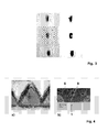
- Fig. 2a - c show a typical overspray situation for a cooling hole 5 of the article 1 with a diffuser outlet that has been drilled at an angle of 30° to the surface.
- Overspray coating 6 has been deposited in a local area 8 onto the diffuser outlet of the hole 5.
- the picture below illustrates the situation for the same hole 5 before (Fig. 2b) and after removal (Fig. 2c) of the overspray coating 6.
- Position information for all holes is saved in a component specific file with a unique identifier.
- the component can be removed from the fixture for further machining steps such as re-coating. Removal of the overspray can be done on the same workcell that was used for hole detection. Alternatively, the precision machining uses a separate workcell dedicated for this purpose. In both cases the local co-ordinate system is re-established using the same unchanged characteristic features of the component as those used for previous determination of the local co-ordinate system.
- a CNC or robot program is then activated in order to position and move the component and laser beam relative to each other. This movement is made in a way that the original geometry can be reproduced by precision machining and any residual coating is removed from the cooling passage.
- the information from a conoscopic probe can be used without changing the orientation of the processing head.
- the information from the conoscopic probe can as well be used to adapt the material removal strategy.
- the coating is taken off by local evaporation using a q-switched Nd-YAG laser.
- the laser beam is scanned over the surface of the cooling hole and the overspray is removed layer by layer.
- the pulsed laser must be capable of producing intensities in the range from 2*10 7 W/cm 2 to 5*10 8 W/cm 2 at typical standoff distances of 150mm-300mm and at high repetition rates exceeding 10kHz.
- Fig. 5 shows an example for the removal of ceramic TBC overspray coating 6 from a test plate made from superalloy.
- a TBC coating 6 of approx. 450 ⁇ m thickness was removed in less than 10s.
- Quick and accurate movement of the laser beam was achieved with the help of a galvano-scanner head. No damage occurred to the base material and the thickness of the recast layer 8 could be kept below 50 ⁇ m.
Abstract
Description
- The invention relates to an automated machining process for machining of an obstructed passage of an article according to the step of the independent claim.
- During the last decades the performance of gas turbine components has increased continuously. New, advanced materials have been introduced in order to comply with the high firing temperatures of modern engines. At the same time, component design has changed from not cooled, bulk components to hollow blades and vanes with a complex internal cooling structure. One of the latest developments is cooling channel configurations with a diffuser outlet, which has typically a fan shape geometry. In this design the diameter of the cylindrical section of the cooling channel defines the total airflow volume, whereas the fan shaped end of the channel results in an advantageous redistribution of the cooling air over the adjacent surface. According to the cooling requirements this film cooling effect can be adjusted by design variations of diffuser outlet.
- The latest generation of these gas turbine components have to withstand hot gas temperatures exceeding the melting point of highly alloyed, high-strength materials. In order to ensure safe and reliable operation of the engine, the designed functionality of the cooling system must be ensured during the whole lifetime of the hot gas path components. For this purpose protective coatings are applied to the outer (and sometimes also inner) surfaces of the parts.
- In modern engines the number of cooling holes per component can be as high as several hundreds. The geometry of the cooling passages depends on their location on the component. It is not unusual that more than 20 different types of cooling holes can be found on a single component.
- A typical manufacturing sequence of such a part starts with the casting. After the following machining a first metallic protection coating (usually of the MCrAIY family, where M is Ni and/or Co) is sprayed onto the component. A second, ceramic thermal barrier coating (TBC) is then deposited on the first coating. For most gas turbine components the thickness of either coating is in the range from 100µm to 600µm.
- Cooling holes are only machined after both coatings have been deposited. The use of high power, pulsed lasers is common for this purpose. In most cases an initial start hole is created by percussion drilling, followed by a trepanning step that machines the precise contour of the cooling passage. This process is usually fully automated using expensive 5-axis CNC workcells equipped with a powerful Nd-YAG laser.
- Problems arise when such a complex component returns after service. Gas turbine blades and vane are normally designed for an overall lifetime of several 10000 operating hours. The protective coatings, however, are consumed earlier and have to be renewed several times during this period. This is in conflict with the requirement that the original airflow must be maintained. Many attempts have been made in order to mask cooling holes and to avoid the deposition of coating powder in the cooling channels. Several techniques use masking material either in the form of UV curable material (US-A-5,726,348, US-B1-6,265,022), epoxy, resin or organic material (EP-A2-1 245 691, EP-A1-1 076 106, US-A-5,800,695), or fugitive plugs (US-A-4,743,462). Often the masking material has to be applied in a time consuming manual process, e.g. with a syringe. A suitable etching or heat treatment can subsequently remove the masking material. However, these masking materials do normally not withstand the high temperatures that occur during the plasma deposition of the MCrAIY coating layer, where preheating temperatures exceed 700°C followed by diffusion bonding heat treatment where temperatures rise above 1000°C. This is also the case for the fugitive plug approach as disclosed in US-A-4,743,462 where the plug is made from plastic material that volatises at a temperature below that of the deposition process.
- Due to the considerable number of different exit fan shapes and tolerances in original manufacturing it is also not practicable to fabricate shadowing masks that could be applied from the outer surface of the part. It is thus desirable to establish a process which does not require any masking and that allows to remove overspray material in a precise and economic way.
- The most straightforward method to achieve this goal is manual re-drilling of the partially plugged cooling holes. However, it is usually not easy to identify the precise location of the cooling channels in the oversprayed condition, as a part of the hole may be hidden under the renewed coating. Additionally, even for skilled operators it is not possible to re-contour the fan to the original shape in a reasonable time. As a consequence, the re-drilling operation becomes either prohibitively expensive and time-consuming, or the original cooling effect of the passage is modified in a non-acceptable way.
- US-A-5,702,288 offers a solution to this problem. An abrasive slurry is forced through the cooling holes from the inside of the component thus removing residual overspray coating. However, this approach also abrades the other walls of the cooling channels and thus affects the overall performance of the cooling system.
- Laser drilling offers an attractive solution for the manufacturing of cooling channels and it is thus evident to use this method for the redrilling process. A number of techniques have been patented for the laser machining of cooling holes in gas turbine components e.g. US-B1-6,420,677, WO 02/32614, US-B1-6,359,254, US-B1-6,329,632 or US-B1-6,307,175. However, these methods do not provide a suitable solution for the repair process, where the component may have undergone dimensional changes during service. Repair of such parts requires accurately locating the new position of the cooling channel which is usually different from the original location. In addition, only the blocked part of the cooling hole has to be re-machined without causing damage to the back or side walls of the cooling channels. For this purpose the high pulse energies of conventional flash lamp pumped lasers as those cited in patents US-B1-6,420,677, WO 02/32614, US-B1-6,359,254, US-B1-6,329,632 or US-B1-6,307,175 are not suitable, because the energy input per pulse is too high and the volume affected by the laser pulse too big. On the other hand, if the pulse energy of is reduced by external attenuation the small repetition rates of these conventional drilling lasers do no longer allow an economic process.
- The opening of substantially blocked cooling holes with an excimer laser operating in the UV has been disclosed in US-A-5,216,808. The advantage of this type of laser is the high absorption of the UV wavelength in ceramic material such as TBC, which leads to effective material removal. It is claimed that due to the short pulse length and higher photon energy at the UV wavelength TBC is removed athermally by photo-ablation, resulting in negligible heat input into the material. However, this advantage is less pronounced for the metallic MCrAIY coating beneath the TBC layer. Furthermore, solid state lasers as such of the Nd-YAG type are generally preferred by the industry for material processing due to their proven reliability and widespread use.
- US-B1-6,172,331 and US-A-6,054,673 give a suitable example of a solid state laser, which is capable to drill both metallic and ceramic material. Here, a Nd-YAG laser is used in the q-switch mode, where short pulses of less than 500ns duration are generated. In the q-switched mode the peak pulse power is high enough to remove the material mostly as vapour instead of melt ejection which common for conventional drilling. The energy per laser pulse is small and it is thus possible to detect hole breakthrough with a suitable device before significant damage to the wall behind the cooling hole occurs. Although the use of such a laser is desirable, it is not disclosed how the process can be advantageously applied for the repair of components that have undergone dimensional changes or where the cooling hole is only partially obstructed. Furthermore, the focus of these patents is the interruption of the drilling process directly after the detection of breakthrough (US-A-6,054,673) and the additional use of a frequency multiplied component from the same laser which results in a shorter wavelength and thus higher absorption in metallic and ceramic material (US-A-6,172,331). It is interesting to note, that US-A-6,172,331 distinguishes the use of additional harmonic generation from the use of only the original wavelength. A process parameter window covering pulse peak powers from 105 W to 107 W is claimed. However, under certain conditions it is also possible to achieve evaporation of coating material with short pulses at smaller peak power <105 W, which is advantageous, because it reduces the power requirements for the laser source.
- The modification and repair of film cooling holes in gas turbine components is described in US-B1-6,243,948, where the cooling hole outlets are enlarged and any portion which might exhibit cracks is removed. Although the inlet of these cooling channels is not modified and thus the total airflow change is very small, the enlargement of the outlets changes the film cooling effect and thus the performance of the component. No details are given about the hole detection or the machining step and how both can be carried out in a precise and economic way.
- Such an automated method is suggested in US-B1-6,380,512 where a laser drilling process is disclosed to remove coating material from (partially) blocked cooling passages. The method relies on a 5-axes CNC workcell and a CNC component program with pre-programmed locations of the cooling holes. The drilling apparatus is equipped with a vision system and can thus compensate for component deformation or deviation from blueprint dimensions. The vision equipment is used to determine the actual location of the cooling holes either on the coated component or in a condition where the component is being prepared for coating. The apparatus is equipped with a flash lamp pumped Nd-YAG laser and the vision system is either mounted to the laser such that an image is obtained through the laser lens or it is separated from the laser. With this method it is also possible to remove the component from the fixture that was used for the original drilling, to modify (coat) it thereafter, followed by accurate repositioning and adjustment of the orientation of the component. However, the method does only detect the position of the hole and not the orientation of the channel axis. For this reason only a partial compensation of component deformation and manufacturing tolerances is possible with the disclosed technique. Moreover, as the real orientation of the cooling channels are not detected, it is not possible to align the re-machined diffuser outlet accurately with the cylindrical section, which is left from the original drilling.
- The object of the present invention is to provide a advanced method for a more advanced and powerful automated, adaptive machining method allowing to remove residual material from obstructed cooling passages.
- The process according to the present invention is divided into a first step which comprises the detection of the obstructed passages and a second step which comprises a machining step for the removal of obstructing material, which can be carried out on the same or on separate workcells.
- During the first inventive step a local reference co-ordinate system is created which uses characteristic features of the article such as corners or grooves. An automated scanning vision system is used to obtain actual 3D information of the position and orientations of the cooling passage. This detection process is fully automated and does not require the assistance of an operator. The position and orientation of the cooling passage are established with respect to a local reference co-ordinate system which can precisely re-established at a later date. In this way, it is possible to make use of stored hole position and orientation data after intermediate machining steps such as re-coating. As a particular example of the present invention, the hole position and orientation data is saved in a file that contains a unique identifier for the article.
- In a second process step of the inventive method the data contained in this file is used for a precision machining operation, where residual material from a re-coating operation is removed from the cooling holes. In this way, a desired cooling flow rate and a favorable film distribution of the cooling medium can be re-established. Unwanted material could be overspray coating, other material plugging the cooling passages, recast from the original drilling or base material, if the intention is to enlarge a diffuser-end portion of the cooling passage. This is valid for a cooling passage of a turbine component which has a part with cylindrical cross section ending in a diffusor opening. Then, the part with the cylindrical section defines the total amount of cooling fluid that can be guided through the passage.
- The position of each passage is a reference point that is obtained from the intersection of the channel axis with a local tangential surface plane. The local tangential plane can be established with any suitable measurement device, e.g. touch probes, eddy current sensors, optical triangulation sensors, conoscopic sensors, interferometers.
- The precision machining operation is either carried out on a dedicated machining workcell (CNC or robotic system) or on the same workcell that was originally used to acquire hole position and orientation data. Advantageously, a high power q-switched or precision drilling solid state laser or waterjet drilling is used for the precision machining operation, e.g. the removal of the unwanted material that prevents the desired flow of the cooling medium.
- Further advantageous embodiments of the present invention are given in dependent claims.
- Preferred embodiments of the invention are illustrated in the accompanying drawings, in which
- Fig. 1
- illustrates a gas turbine blade as an example of an article,
- Fig. 2 a-c
- shows an oversprayed surface of the article and cross sections of the cooling hole before (Fig. 2b) and after (Fig. 2c) redrilling,
- Fig. 3
- shows a row of 3 cooling holes as seen by the vision system and
- Fig. 4 a, b
- illustrates the removal of a TBC overspray with high power q-switched Nd-YAG laser.
- The drawings show only the parts important for the invention. Same elements will be numbered in the same way in different drawings.
- As an example Fig. 1 shows an
article 1 such as blades or vanes of gas turbine engines, the gas turbine blade comprising aroot portion 2, aplatform 3 and ablade 4 and cooling holes 5. On the external surface 7 a MCrAIY-coating and/or athermal barrier coating 6 is applied. The component can be made from a Nickel base superalloy known in the state of the art, e.g. from the documents US-A-5,888,451, US-A-5,759,301 or from US-A-4,643,782, which is known as "CMSX-4". - The process according to the present invention is divided into a first step which comprises the detection of the
cooling passages 5 and a second step which comprises a machining step, which can be carried out on the same or on separate workcells. - After mounting the component in a fixture in the detection/vision workcell, a local reference co-ordinate system is established. It is important to note that characteristic features of the component itself are used for establishing this reference co-ordinate system. The characteristic features are chosen such that subsequent machining steps do not affect them. Example features are machined side surfaces, corners and rims, or sealing groves. Using such fixed features for the determination of the local co-ordinate system, the component can be later put into another workcell, where it is possible to re-establish the same co-ordinate system. All hole locations and hole orientations are saved with respect to this local reference co-ordinate system. This is an important advantage as the local hole co-ordinates can be reused at any time without tedious alignment of the part. For instance, the local co-ordinates can be used for the re-opening of
cooling holes 5 after the deposition of newprotective coatings 6 with thermal spray process. No sophisticated fixtures are required, as mounting misfit has no influence on the local co-ordinate system and on the local hole co-ordinates. - The workcell for the detection of
cooling holes 5 is based on a robot equipped with a vision system and an optical sensor. In order to enhance the performance of the robot, absolute accuracy calibration techniques can be applied prior to the use of this system. The absolute accuracy calibration of the robot allows to establish a better cinematic model of the robot axes and results in improved accuracy. This enhanced performance is a crucial factor if flexible 6-arm robots are to be used for hole detection and/or precision machining. The following techniques are used for this purpose: - i) a so-called 'absolute calibration' is implemented. This calibration e-sults in a more precise cinematic model of the robot and in enhanced accuracy,
- ii) an error-mapping table is established and used to compensate for residual deviations between position data indicated by the robot and the real, absolute position. The error-mapping table can be obtained with the help of a reference (master) component, which has been prepared with features that can be accurately measured. For instance, it is possible to fix mechanically drilled brass coupons onto the component's surface. The holes on these brass coupons can be accurately pinned and measured on a CMM (co-ordinate measurement machine), which is not possible for the original, laser-drilled holes. In this way, an error map can be established by comparing reference position data from the CMM with data from the hole detection workcell at positions of interest. With the error map it is then possible to apply position dependent corrections to the indicated positions and orientations.
-
- As seen in Fig. 3, the 3D position of each cooling channel is a reference point that is obtained from the intersection of the channel axis with a local tangential surface plane. The local tangential plane can be established with any suitable measurement device, e.g. touch probes, eddy current sensors, optical triangulation sensors, conoscopic sensors, interferometers. A preferred solution makes use of an optical distance sensor. After a calibration of the sensor's tool centre point (TCP) it collects 3D-position information from the tangential surface that surrounds the cooling hole under inspection. A plane is then fitted through a suitable number of measurement points (e.g. 5 measurement points as seen in Fig. 3). Using information from original manufacturing (CAD data) the vision system is positioned in a start position which is close to the real location of the cooling hole. Images are taken at various angles and the optimum alignment with the cooling channels is derived from automated image processing using advanced image analysis tools. After alignment, the vision system automatically determines the centre of gravity of the cooling passage and positions the robot accordingly. The 3D-reference position of the
cooling passage 5 is obtained from the intersection of the local tangential plane with the symmetry axis of the aligned vision system. - In a second process step the data contained in this file is used for a precision machining operation, where residual material from a re-coating operation is removed from the cooling holes 5. In this way, a desired cooling flow rate and a favorable film distribution of the cooling medium can be re-established. Unwanted material could be
overspray coating 6, other material plugging the cooling passages, recast from the original drilling or base material, if the intention is to enlarge a diffuser-end portion of thecooling passage 5. An example is the machining of acooling passage 5 which has a part with cylindrical cross section ending in a diffusor opening. Then, the part with the cylindrical section defines the total amount of cooling fluid that can be guided through thepassage 5. - Due to the adoption of adaptive machining techniques and the use of on-line vision equipment the method compensates for component deformation that may have occurred during previous operation in the field. At the same time it takes tolerances of original manufacturing and deviations from original design geometry fully into account.
- The precision machining operation is either carried out on a dedicated machining workcell (CNC or robotic system) or on the same workcell that was originally used to acquire hole position and orientation data. Advantageously, a high power q-switched or precision drilling solid state laser or waterjet drilling is used for the precision machining operation, e.g. the removal of the unwanted material that prevents the desired flow of the cooling medium.
- The method offers an economical way of (re)-establishing a desired airflow rate and cooling air distribution. It is fully automated and combines a hole detection and subsequent precision machining step on two dedicated workcells.
- Fig. 2a - c show a typical overspray situation for a
cooling hole 5 of thearticle 1 with a diffuser outlet that has been drilled at an angle of 30° to the surface.Overspray coating 6 has been deposited in alocal area 8 onto the diffuser outlet of thehole 5. The picture below illustrates the situation for thesame hole 5 before (Fig. 2b) and after removal (Fig. 2c) of theoverspray coating 6. - Position information for all holes is saved in a component specific file with a unique identifier. After identification of the cooling hole positions the component can be removed from the fixture for further machining steps such as re-coating. Removal of the overspray can be done on the same workcell that was used for hole detection. Alternatively, the precision machining uses a separate workcell dedicated for this purpose. In both cases the local co-ordinate system is re-established using the same unchanged characteristic features of the component as those used for previous determination of the local co-ordinate system. A CNC or robot program is then activated in order to position and move the component and laser beam relative to each other. This movement is made in a way that the original geometry can be reproduced by precision machining and any residual coating is removed from the cooling passage.
- To determine the machined volume the information from a conoscopic probe can be used without changing the orientation of the processing head. The information from the conoscopic probe can as well be used to adapt the material removal strategy.
- Advantageously the coating is taken off by local evaporation using a q-switched Nd-YAG laser. The laser beam is scanned over the surface of the cooling hole and the overspray is removed layer by layer. For an economic operation, the pulsed laser must be capable of producing intensities in the range from 2*107 W/cm2 to 5*108 W/cm2 at typical standoff distances of 150mm-300mm and at high repetition rates exceeding 10kHz.
- Fig. 5 shows an example for the removal of ceramic
TBC overspray coating 6 from a test plate made from superalloy. Using 15kHz laser pulses, aTBC coating 6 of approx. 450 µm thickness was removed in less than 10s. Quick and accurate movement of the laser beam was achieved with the help of a galvano-scanner head. No damage occurred to the base material and the thickness of the recastlayer 8 could be kept below 50 µm. -
- 1
- Article
- 2
- Root portion
- 3
- Platform
- 4
- Blade
- 5
- Cooling hole, cooling passage
- 6
- Coating
- 7
- External surface of
article 1 - 8
- Area
- 9
- Recast layer
Claims (19)
- An automated machining process for machining of an obstructed passage (5) of an article (1) having a body, comprising the steps ofderiving the position and orientation of the passage (5) from automated processing of images of the passage (5) and additional information from a distance measurement device,saving positions and orientations of the passage (5) as local coordinates with respect to a reference coordinate system attached to the article's body that surrounds the passage (5) andusing the saved positions and orientations of the passage (5) for subsequent removal of unwanted obstructing material from the obstructed passage (5).
- The process of claim 1, comprising the step of machining an obstructed cooling passage (5) of said article (1).
- The process of claim 2, comprising the step of machining a cooling passage (5) which has a cylindrical cross section ending in adiffusor opening.
- The process of any of the claims 1 to 3, comprising the step of machining an obstructed passage (5), wherein the obstruction of the passage originates from the application of a coating process of the surface of the article (1 ).
- The process of any of the claims 1 to 4, comprising the step of machining obstructed passages (5) of an article (1) made from asuperalloy.
- The process of any of the claims 1 to 5, comprising the step of machining obstructed passages (5) of a turbine component.
- The process of any of the claims 1 to 6, comprising the step of using the same or a different apparatus for the steps of deriving the position and orientation of the passage (5) and for the subsequent step of removal of the obstructing material.
- The process of claim 7, comprising the step of making the passage (5) detection and machining steps on the same machine and removing the article (1) from its fixture at least once between the detection and machining of the passage (5).
- The process of any of the claims 1 to 8, comprising the step of applying additional offset corrections prior to the step of machining of the obstructed passage by using the known orientation data obtained from the previous detection step.
- The process of any of the claims 1 to 9, comprising the step of deriving the reference coordinate system from characteristic features that are part of the article (1) and that are not changed by subsequent machining steps.
- The process of any of the claims 1 to 10, comprising the step of making the identification of the passage with the help of a robot or CNC system which is equipped with a vision system and at least one additional sensing device from the group of touch probes, eddy current sensors, optical triangulation sensors, conoscopic sensors, interferometers.
- The process of any of the claims 1 to 11, comprising the step of using the information from a conoscopic probe to determine the machined volume without changing the orientation of the processing head.
- The process of any of the claims 1 to 12, comprising the step of using the information from a conoscopic probe to adapt the material removal strategy.
- The process of any of the claims 1 to 13, comprising the step of characterizing the position of the passage (5) by at least one point in space obtained from the intersection of a surface plane and a line that is correlated with a characteristic feature of the passage (5).
- The process of any of the claims 1 to 14, comprising the step of using a pulsed solid state laser for subsequent precision machining of the passages (5).
- The process of claim 15, comprising the steps of using a robot or CNC to position the article (1) containing the passages (5) relative to the laser beam and the relative movement between laser beam and article (1) is achieved with an additional galvano-scanner head.
- The process of any of the claims 1 to 14, comprising the step of using waterjet drilling for subsequent precision machining of the passages (5).
- The process of any of the claims 1 to 17, comprising the step of improving the accuracy of the detection step by absolute accuracy calibration of the apparatus used for that purpose.
- The process of any of the claims 1 to 17, comprising the step of improving the accuracy of the detection step by establishing an error map for the detection and machining workcells and by using the error maps for compensation of positioning errors.
Priority Applications (6)
| Application Number | Priority Date | Filing Date | Title |
|---|---|---|---|
| DE60316942T DE60316942T2 (en) | 2003-08-27 | 2003-08-27 | Adaptive automated processing of crowded channels |
| AT03103232T ATE375841T1 (en) | 2003-08-27 | 2003-08-27 | ADAPTIVE AUTOMATED PROCESSING OF CROWDED CHANNELS |
| EP03103232A EP1510283B1 (en) | 2003-08-27 | 2003-08-27 | Automated adaptive machining of obstructed passages |
| PCT/EP2004/051801 WO2005021205A1 (en) | 2003-08-27 | 2004-08-16 | Automated adaptive machining of obstructed passages |
| MYPI20043459A MY135867A (en) | 2003-08-27 | 2004-08-25 | Automated adaptive machining of obstructed passages |
| US11/276,297 US7329832B2 (en) | 2003-08-27 | 2006-02-23 | Automated adaptive machining of obstructed passages |
Applications Claiming Priority (1)
| Application Number | Priority Date | Filing Date | Title |
|---|---|---|---|
| EP03103232A EP1510283B1 (en) | 2003-08-27 | 2003-08-27 | Automated adaptive machining of obstructed passages |
Publications (2)
| Publication Number | Publication Date |
|---|---|
| EP1510283A1 true EP1510283A1 (en) | 2005-03-02 |
| EP1510283B1 EP1510283B1 (en) | 2007-10-17 |
Family
ID=34089733
Family Applications (1)
| Application Number | Title | Priority Date | Filing Date |
|---|---|---|---|
| EP03103232A Expired - Lifetime EP1510283B1 (en) | 2003-08-27 | 2003-08-27 | Automated adaptive machining of obstructed passages |
Country Status (6)
| Country | Link |
|---|---|
| US (1) | US7329832B2 (en) |
| EP (1) | EP1510283B1 (en) |
| AT (1) | ATE375841T1 (en) |
| DE (1) | DE60316942T2 (en) |
| MY (1) | MY135867A (en) |
| WO (1) | WO2005021205A1 (en) |
Cited By (21)
| Publication number | Priority date | Publication date | Assignee | Title |
|---|---|---|---|---|
| EP1739410A1 (en) * | 2005-06-28 | 2007-01-03 | United Technologies Corporation | Systems and methods for determining the location and angular orientation of a hole with an obstructed opening residing on a surface of an article |
| EP1739409A1 (en) * | 2005-06-28 | 2007-01-03 | United Technologies Corporation | Thermal imaging and laser scanning systems and methods for determining the location and angular orientation of a hole with an obstructed opening residing on a surface of an article |
| EP1767743A1 (en) * | 2005-09-26 | 2007-03-28 | Siemens Aktiengesellschaft | Method to produce a coated gas turbine component having opening holes, apparatus to perform the method and coated turbine blade having cooling holes |
| EP1844892A1 (en) * | 2006-04-13 | 2007-10-17 | ALSTOM Technology Ltd | Method of laser removing of coating material from cooling holes of a turbine component |
| EP2123788A3 (en) * | 2008-04-29 | 2010-10-27 | Huffman Corporation | Method and apparatus for stripping holes in a metal substrate |
| EP2312122A1 (en) * | 2009-10-15 | 2011-04-20 | Siemens Aktiengesellschaft | Reference determination for calculating the position of blocked holes, device and machining device |
| EP2314987A1 (en) * | 2009-10-20 | 2011-04-27 | Siemens Aktiengesellschaft | Surface analysis and device for detecting closed holes |
| EP2322683A1 (en) * | 2009-11-16 | 2011-05-18 | Siemens Aktiengesellschaft | Coating method for a component with partially closed holes and method for opening the holes |
| JP2011157964A (en) * | 2010-01-29 | 2011-08-18 | General Electric Co <Ge> | Process and system for forming shaped air hole |
| EP2317076A3 (en) * | 2009-10-30 | 2011-08-24 | Alstom Technology Ltd | A method for repairing a gas turbine component |
| EP2385214A1 (en) * | 2010-05-06 | 2011-11-09 | Siemens Aktiengesellschaft | Method for determining the position of obstructed holes, device and machining device |
| EP2386824A1 (en) * | 2010-05-12 | 2011-11-16 | Siemens Aktiengesellschaft | Surface analysis and device for detecting closed holes and device for opening them again |
| EP2428765A1 (en) * | 2010-09-14 | 2012-03-14 | Siemens Aktiengesellschaft | Method and device for processing turbine blades |
| JP2012122432A (en) * | 2010-12-10 | 2012-06-28 | Mitsubishi Heavy Ind Ltd | Hole location specification device of coating member |
| WO2012100999A1 (en) * | 2011-01-26 | 2012-08-02 | Siemens Aktiengesellschaft | Method and device for inspecting an object for the detection of surface damage |
| EP2599960A1 (en) * | 2011-12-02 | 2013-06-05 | United Technologies Corporation | Turbomachine component machining method |
| US8905713B2 (en) | 2010-05-28 | 2014-12-09 | General Electric Company | Articles which include chevron film cooling holes, and related processes |
| EP2950942A4 (en) * | 2013-01-30 | 2016-04-27 | United Technologies Corp | Coating process for gas turbine engine component with cooling holes |
| US10113435B2 (en) | 2011-07-15 | 2018-10-30 | United Technologies Corporation | Coated gas turbine components |
| US10265804B2 (en) * | 2005-09-06 | 2019-04-23 | Mtu Aero Engines Gmbh | Process and system for producing holes in turbine and other components |
| WO2020011673A1 (en) * | 2018-07-09 | 2020-01-16 | Siemens Aktiengesellschaft | Device and method for analyzing the surface of parts having cooling fluid openings |
Families Citing this family (16)
| Publication number | Priority date | Publication date | Assignee | Title |
|---|---|---|---|---|
| US7574035B2 (en) * | 2006-04-07 | 2009-08-11 | United Technologies Corporation | System and method for inspection of hole location on turbine airfoils |
| US8739404B2 (en) * | 2010-11-23 | 2014-06-03 | General Electric Company | Turbine components with cooling features and methods of manufacturing the same |
| US9089933B2 (en) | 2010-12-20 | 2015-07-28 | Pratt & Whitney Canada Corp. | Method for making and repairing effusion cooling holes in cumbustor liner |
| US20120164376A1 (en) | 2010-12-23 | 2012-06-28 | General Electric Company | Method of modifying a substrate for passage hole formation therein, and related articles |
| EP2737965A1 (en) * | 2012-12-01 | 2014-06-04 | Alstom Technology Ltd | Method for manufacturing a metallic component by additive laser manufacturing |
| WO2014151479A2 (en) * | 2013-03-22 | 2014-09-25 | Videojet Technologies Inc. | Method of removing a coating of a substrate |
| US9348001B2 (en) | 2013-10-21 | 2016-05-24 | General Electric Company | Method and system for detecting surface features on turbine components |
| US9707645B2 (en) * | 2014-01-09 | 2017-07-18 | General Electric Company | Systems, methods, and apparatus for locating and drilling closed holes of a turbine component |
| DE102014204806A1 (en) * | 2014-03-14 | 2015-09-17 | Siemens Aktiengesellschaft | Process for the re-production of through holes in a layer system |
| US9746848B2 (en) | 2014-11-15 | 2017-08-29 | Advanced Simulation Technology, Incorporated | System and method for adaptive positioning of a work piece |
| US11752573B2 (en) | 2017-08-07 | 2023-09-12 | Rtx Corporation | Laser clearance of coating |
| SG10201708210PA (en) | 2017-10-05 | 2019-05-30 | United Technologies Corp | Multi-step clearance of coating |
| US11407067B2 (en) * | 2018-06-29 | 2022-08-09 | Pratt & Whitney Canada Corp. | Method for repairing a part |
| US10955815B2 (en) | 2018-11-09 | 2021-03-23 | Raytheon Technologies Corporation | Method of manufacture using autonomous adaptive machining |
| US11413703B2 (en) | 2019-05-22 | 2022-08-16 | General Electric Company | Method of forming cooling holes |
| US11840032B2 (en) * | 2020-07-06 | 2023-12-12 | Pratt & Whitney Canada Corp. | Method of repairing a combustor liner of a gas turbine engine |
Citations (5)
| Publication number | Priority date | Publication date | Assignee | Title |
|---|---|---|---|---|
| US5216808A (en) * | 1990-11-13 | 1993-06-08 | General Electric Company | Method for making or repairing a gas turbine engine component |
| EP0916445A2 (en) * | 1997-11-12 | 1999-05-19 | ROLLS-ROYCE plc | A method of coating a component |
| GB2345455A (en) * | 1999-01-06 | 2000-07-12 | M J Tech Ltd | Method of micromachining aerofoil components |
| US6380512B1 (en) * | 2001-10-09 | 2002-04-30 | Chromalloy Gas Turbine Corporation | Method for removing coating material from a cooling hole of a gas turbine engine component |
| EP1310632A1 (en) * | 2001-11-09 | 2003-05-14 | GE Aviation Services Operation (Pte) Ltd. | Method and apparatus for correcting airfoil twist |
Family Cites Families (17)
| Publication number | Priority date | Publication date | Assignee | Title |
|---|---|---|---|---|
| US4663511A (en) * | 1986-05-02 | 1987-05-05 | The United States Of America As Represented By The United States Department Of Energy | Stereoscopic optical viewing system |
| US5125035A (en) * | 1989-12-18 | 1992-06-23 | Chromalloy Gas Turbine Corporation | Five axis generated hole inspection system |
| DE4207169A1 (en) * | 1992-03-06 | 1993-09-09 | Siemens Solar Gmbh | Laser operations on a workpiece with uneven surface - where distances between workpiece and laser are measured during intervals between working pulses |
| US5841099A (en) * | 1994-07-18 | 1998-11-24 | Electro Scientific Industries, Inc. | Method employing UV laser pulses of varied energy density to form depthwise self-limiting blind vias in multilayered targets |
| US6044308A (en) * | 1997-06-13 | 2000-03-28 | Huissoon; Jan Paul | Method and device for robot tool frame calibration |
| US6748112B1 (en) * | 1998-07-28 | 2004-06-08 | General Electric Company | Method and apparatus for finding shape deformations in objects having smooth surfaces |
| EP1245691A3 (en) | 1999-08-09 | 2002-11-13 | Alstom | Mask material |
| US6611731B2 (en) * | 1999-12-13 | 2003-08-26 | M J Technologies Limited | Micromachining aerofoil components |
| US6573474B1 (en) | 2000-10-18 | 2003-06-03 | Chromalloy Gas Turbine Corporation | Process for drilling holes through a thermal barrier coating |
| US6909800B2 (en) * | 2000-12-15 | 2005-06-21 | United Technologies Corporation | Process and apparatus for locating coated cooling holes on turbine vanes |
| US6720567B2 (en) * | 2001-01-30 | 2004-04-13 | Gsi Lumonics Corporation | Apparatus and method for focal point control for laser machining |
| US6522993B1 (en) * | 2001-09-14 | 2003-02-18 | General Electric Company | Method and system for marking surface deviations on a three dimensional surface |
| EP1319632A1 (en) | 2001-12-13 | 2003-06-18 | Klimapol Sp.Z O.O.J.V. | Process and device for drying of sludge, in particular sewage sludge |
| WO2003058158A2 (en) * | 2001-12-28 | 2003-07-17 | Applied Precision, Llc | Stereoscopic three-dimensional metrology system and method |
| US6847004B2 (en) * | 2003-01-10 | 2005-01-25 | General Electric Company | Process of removing a ceramic coating deposit in a surface hole of a component |
| US6723951B1 (en) * | 2003-06-04 | 2004-04-20 | Siemens Westinghouse Power Corporation | Method for reestablishing holes in a component |
| US6977356B2 (en) * | 2003-09-30 | 2005-12-20 | United Technologies Corporation | Stereovision guided laser drilling system |
-
2003
- 2003-08-27 EP EP03103232A patent/EP1510283B1/en not_active Expired - Lifetime
- 2003-08-27 DE DE60316942T patent/DE60316942T2/en not_active Expired - Lifetime
- 2003-08-27 AT AT03103232T patent/ATE375841T1/en not_active IP Right Cessation
-
2004
- 2004-08-16 WO PCT/EP2004/051801 patent/WO2005021205A1/en active Application Filing
- 2004-08-25 MY MYPI20043459A patent/MY135867A/en unknown
-
2006
- 2006-02-23 US US11/276,297 patent/US7329832B2/en not_active Expired - Fee Related
Patent Citations (5)
| Publication number | Priority date | Publication date | Assignee | Title |
|---|---|---|---|---|
| US5216808A (en) * | 1990-11-13 | 1993-06-08 | General Electric Company | Method for making or repairing a gas turbine engine component |
| EP0916445A2 (en) * | 1997-11-12 | 1999-05-19 | ROLLS-ROYCE plc | A method of coating a component |
| GB2345455A (en) * | 1999-01-06 | 2000-07-12 | M J Tech Ltd | Method of micromachining aerofoil components |
| US6380512B1 (en) * | 2001-10-09 | 2002-04-30 | Chromalloy Gas Turbine Corporation | Method for removing coating material from a cooling hole of a gas turbine engine component |
| EP1310632A1 (en) * | 2001-11-09 | 2003-05-14 | GE Aviation Services Operation (Pte) Ltd. | Method and apparatus for correcting airfoil twist |
Cited By (41)
| Publication number | Priority date | Publication date | Assignee | Title |
|---|---|---|---|---|
| EP1739409A1 (en) * | 2005-06-28 | 2007-01-03 | United Technologies Corporation | Thermal imaging and laser scanning systems and methods for determining the location and angular orientation of a hole with an obstructed opening residing on a surface of an article |
| EP1739410A1 (en) * | 2005-06-28 | 2007-01-03 | United Technologies Corporation | Systems and methods for determining the location and angular orientation of a hole with an obstructed opening residing on a surface of an article |
| US10265804B2 (en) * | 2005-09-06 | 2019-04-23 | Mtu Aero Engines Gmbh | Process and system for producing holes in turbine and other components |
| US20090220349A1 (en) * | 2005-09-26 | 2009-09-03 | Hans-Thomas Bolms | Method for Producing a Gas Turbine Component Which is to be Coated, With Exposed Holes, Device for Carrying Out the Method, and Coatable Turbine Blade with Film Cooling Holes |
| WO2007036437A1 (en) * | 2005-09-26 | 2007-04-05 | Siemens Aktiengesellschaft | Method of producing a gas turbine component to be coated having exposed openings, apparatus for carrying out the method, and coatable turbine blade having a film-cooling opening |
| US8414264B2 (en) | 2005-09-26 | 2013-04-09 | Siemens Aktiengesellschaft | Method for producing a gas turbine component which is to be coated, with exposed holes, device for carrying out the method, and coatable turbine blade with film cooling holes |
| EP2602433A1 (en) * | 2005-09-26 | 2013-06-12 | Siemens Aktiengesellschaft | Method to produce a coated gas turbine component having opening holes, apparatus to perform the method and coated turbine blade having cooling holes |
| EP1767743A1 (en) * | 2005-09-26 | 2007-03-28 | Siemens Aktiengesellschaft | Method to produce a coated gas turbine component having opening holes, apparatus to perform the method and coated turbine blade having cooling holes |
| EP1844892A1 (en) * | 2006-04-13 | 2007-10-17 | ALSTOM Technology Ltd | Method of laser removing of coating material from cooling holes of a turbine component |
| EP1844893A1 (en) * | 2006-04-13 | 2007-10-17 | ALSTOM Technology Ltd | Method of laser removing of coating material from cooling holes of a turbine component |
| US7725210B2 (en) | 2006-04-13 | 2010-05-25 | Alstom Technology Ltd | Method of processing turbine components |
| EP2123788A3 (en) * | 2008-04-29 | 2010-10-27 | Huffman Corporation | Method and apparatus for stripping holes in a metal substrate |
| US8380338B2 (en) | 2008-04-29 | 2013-02-19 | Huffman Corporation | Method and apparatus for stripping holes in a metal substrate |
| EP2312122A1 (en) * | 2009-10-15 | 2011-04-20 | Siemens Aktiengesellschaft | Reference determination for calculating the position of blocked holes, device and machining device |
| WO2011045343A1 (en) * | 2009-10-15 | 2011-04-21 | Siemens Aktiengesellschaft | Reference determination for ascertaining the positions of closed holes, device and machining device |
| WO2011047995A1 (en) * | 2009-10-20 | 2011-04-28 | Siemens Aktiengesellschaft | Surface analysis for detecting closed holes, and device |
| EP2314987A1 (en) * | 2009-10-20 | 2011-04-27 | Siemens Aktiengesellschaft | Surface analysis and device for detecting closed holes |
| US8437010B2 (en) | 2009-10-20 | 2013-05-07 | Siemens Aktiengesellschaft | Surface analysis for detecting closed holes, and device |
| EP2317076A3 (en) * | 2009-10-30 | 2011-08-24 | Alstom Technology Ltd | A method for repairing a gas turbine component |
| US8980372B2 (en) | 2009-11-16 | 2015-03-17 | Siemens Aktiengesellschaft | Process for coating a component having partially closed holes and process for opening the holes |
| EP2322683A1 (en) * | 2009-11-16 | 2011-05-18 | Siemens Aktiengesellschaft | Coating method for a component with partially closed holes and method for opening the holes |
| JP2011157964A (en) * | 2010-01-29 | 2011-08-18 | General Electric Co <Ge> | Process and system for forming shaped air hole |
| US8857055B2 (en) | 2010-01-29 | 2014-10-14 | General Electric Company | Process and system for forming shaped air holes |
| EP2385214A1 (en) * | 2010-05-06 | 2011-11-09 | Siemens Aktiengesellschaft | Method for determining the position of obstructed holes, device and machining device |
| WO2011138415A3 (en) * | 2010-05-06 | 2015-09-03 | Siemens Aktiengesellschaft | Method for determining the position of closed holes, device and processing device |
| EP2386824A1 (en) * | 2010-05-12 | 2011-11-16 | Siemens Aktiengesellschaft | Surface analysis and device for detecting closed holes and device for opening them again |
| WO2011141430A1 (en) * | 2010-05-12 | 2011-11-17 | Siemens Aktiengesellschaft | Surface analysis for detecting closed holes and method for reopening |
| US8905713B2 (en) | 2010-05-28 | 2014-12-09 | General Electric Company | Articles which include chevron film cooling holes, and related processes |
| WO2012035060A1 (en) * | 2010-09-14 | 2012-03-22 | Siemens Aktiengesellschaft | Method for treating turbine blades and device therefor |
| CN103109153A (en) * | 2010-09-14 | 2013-05-15 | 西门子公司 | Method for treating turbine blades and device therefor |
| EP2428765A1 (en) * | 2010-09-14 | 2012-03-14 | Siemens Aktiengesellschaft | Method and device for processing turbine blades |
| US9403245B2 (en) | 2010-09-14 | 2016-08-02 | Siemens Aktiengesellschaft | Method for treating turbine blades and device therefor |
| CN103109153B (en) * | 2010-09-14 | 2016-01-27 | 西门子公司 | For the treatment of method and the equipment thereof of turbo blade |
| JP2012122432A (en) * | 2010-12-10 | 2012-06-28 | Mitsubishi Heavy Ind Ltd | Hole location specification device of coating member |
| WO2012100999A1 (en) * | 2011-01-26 | 2012-08-02 | Siemens Aktiengesellschaft | Method and device for inspecting an object for the detection of surface damage |
| US10113435B2 (en) | 2011-07-15 | 2018-10-30 | United Technologies Corporation | Coated gas turbine components |
| US9052707B2 (en) | 2011-12-02 | 2015-06-09 | United Technologies Corporation | Turbomachine component machining method |
| EP2599960A1 (en) * | 2011-12-02 | 2013-06-05 | United Technologies Corporation | Turbomachine component machining method |
| EP2950942A4 (en) * | 2013-01-30 | 2016-04-27 | United Technologies Corp | Coating process for gas turbine engine component with cooling holes |
| WO2020011673A1 (en) * | 2018-07-09 | 2020-01-16 | Siemens Aktiengesellschaft | Device and method for analyzing the surface of parts having cooling fluid openings |
| US11529704B2 (en) | 2018-07-09 | 2022-12-20 | Siemens Energy Global GmbH & Co. KG | Device and method for analyzing the surface of parts having cooling fluid openings |
Also Published As
| Publication number | Publication date |
|---|---|
| DE60316942T2 (en) | 2008-08-14 |
| EP1510283B1 (en) | 2007-10-17 |
| ATE375841T1 (en) | 2007-11-15 |
| MY135867A (en) | 2008-07-31 |
| DE60316942D1 (en) | 2007-11-29 |
| US7329832B2 (en) | 2008-02-12 |
| US20060157456A1 (en) | 2006-07-20 |
| WO2005021205A1 (en) | 2005-03-10 |
Similar Documents
| Publication | Publication Date | Title |
|---|---|---|
| US7329832B2 (en) | Automated adaptive machining of obstructed passages | |
| US6380512B1 (en) | Method for removing coating material from a cooling hole of a gas turbine engine component | |
| EP1437194B1 (en) | Process of removing a ceramic coating deposit in a surface hole of a component | |
| JP4980360B2 (en) | Method of manufacturing a gas turbine component to be coated with exposed openings, apparatus for carrying out the method, and coatable turbine blade with film cooling openings | |
| US7019257B2 (en) | Laser drilling shaped holes | |
| EP1081239B1 (en) | Method for setting up and controlling confinement media flow in laser shock peening | |
| EP1332016B2 (en) | Process for drilling holes in a metallic workpiece having a thermal barrier coating | |
| US7192622B2 (en) | Process of masking cooling holes of a gas turbine component | |
| JP2007009908A (en) | Specifying method and specifying device for position and angular direction of single or plurality of holes | |
| US7816625B2 (en) | Method for the production of a hole and device | |
| US6611731B2 (en) | Micromachining aerofoil components | |
| EP1832376A2 (en) | System and method for monotoring drilling process parameters and controlling drilling operation | |
| EP2855033B1 (en) | Coating for cooling air holes | |
| US11407067B2 (en) | Method for repairing a part | |
| JP2022510538A (en) | Automatic cooling hole identification and toolpath generation | |
| EP1534457A1 (en) | Method of producing a composite component | |
| Hoebel et al. | Automated laser re-opening of film cooling holes | |
| US20220242001A1 (en) | Method for removing a ceramic coating from a substrate and waterjet machine | |
| VanderWert et al. | Advances in process control for laser drilling | |
| Stackhouse et al. | Methods of employing lasers in the production and repair of cooling holes used in the latest turbine engine designs |
Legal Events
| Date | Code | Title | Description |
|---|---|---|---|
| PUAI | Public reference made under article 153(3) epc to a published international application that has entered the european phase |
Free format text: ORIGINAL CODE: 0009012 |
|
| AK | Designated contracting states |
Kind code of ref document: A1 Designated state(s): AT BE BG CH CY CZ DE DK EE ES FI FR GB GR HU IE IT LI LU MC NL PT RO SE SI SK TR |
|
| AX | Request for extension of the european patent |
Extension state: AL LT LV MK |
|
| 17P | Request for examination filed |
Effective date: 20050825 |
|
| AKX | Designation fees paid |
Designated state(s): AT BE BG CH CY CZ DE DK EE ES FI FR GB GR HU IE IT LI LU MC NL PT RO SE SI SK TR |
|
| 17Q | First examination report despatched |
Effective date: 20060707 |
|
| GRAP | Despatch of communication of intention to grant a patent |
Free format text: ORIGINAL CODE: EPIDOSNIGR1 |
|
| GRAS | Grant fee paid |
Free format text: ORIGINAL CODE: EPIDOSNIGR3 |
|
| GRAA | (expected) grant |
Free format text: ORIGINAL CODE: 0009210 |
|
| AK | Designated contracting states |
Kind code of ref document: B1 Designated state(s): AT BE BG CH CY CZ DE DK EE ES FI FR GB GR HU IE IT LI LU MC NL PT RO SE SI SK TR |
|
| REG | Reference to a national code |
Ref country code: GB Ref legal event code: FG4D |
|
| REG | Reference to a national code |
Ref country code: CH Ref legal event code: EP |
|
| REG | Reference to a national code |
Ref country code: IE Ref legal event code: FG4D |
|
| REF | Corresponds to: |
Ref document number: 60316942 Country of ref document: DE Date of ref document: 20071129 Kind code of ref document: P |
|
| REG | Reference to a national code |
Ref country code: CH Ref legal event code: NV Representative=s name: ALSTOM TECHNOLOGY LTD |
|
| NLV1 | Nl: lapsed or annulled due to failure to fulfill the requirements of art. 29p and 29m of the patents act | ||
| PG25 | Lapsed in a contracting state [announced via postgrant information from national office to epo] |
Ref country code: NL Free format text: LAPSE BECAUSE OF FAILURE TO SUBMIT A TRANSLATION OF THE DESCRIPTION OR TO PAY THE FEE WITHIN THE PRESCRIBED TIME-LIMIT Effective date: 20071017 Ref country code: SE Free format text: LAPSE BECAUSE OF FAILURE TO SUBMIT A TRANSLATION OF THE DESCRIPTION OR TO PAY THE FEE WITHIN THE PRESCRIBED TIME-LIMIT Effective date: 20080117 Ref country code: ES Free format text: LAPSE BECAUSE OF FAILURE TO SUBMIT A TRANSLATION OF THE DESCRIPTION OR TO PAY THE FEE WITHIN THE PRESCRIBED TIME-LIMIT Effective date: 20080128 |
|
| PG25 | Lapsed in a contracting state [announced via postgrant information from national office to epo] |
Ref country code: BG Free format text: LAPSE BECAUSE OF FAILURE TO SUBMIT A TRANSLATION OF THE DESCRIPTION OR TO PAY THE FEE WITHIN THE PRESCRIBED TIME-LIMIT Effective date: 20080117 Ref country code: PT Free format text: LAPSE BECAUSE OF FAILURE TO SUBMIT A TRANSLATION OF THE DESCRIPTION OR TO PAY THE FEE WITHIN THE PRESCRIBED TIME-LIMIT Effective date: 20080317 Ref country code: SI Free format text: LAPSE BECAUSE OF FAILURE TO SUBMIT A TRANSLATION OF THE DESCRIPTION OR TO PAY THE FEE WITHIN THE PRESCRIBED TIME-LIMIT Effective date: 20071017 |
|
| PG25 | Lapsed in a contracting state [announced via postgrant information from national office to epo] |
Ref country code: AT Free format text: LAPSE BECAUSE OF FAILURE TO SUBMIT A TRANSLATION OF THE DESCRIPTION OR TO PAY THE FEE WITHIN THE PRESCRIBED TIME-LIMIT Effective date: 20071017 |
|
| PG25 | Lapsed in a contracting state [announced via postgrant information from national office to epo] |
Ref country code: CZ Free format text: LAPSE BECAUSE OF FAILURE TO SUBMIT A TRANSLATION OF THE DESCRIPTION OR TO PAY THE FEE WITHIN THE PRESCRIBED TIME-LIMIT Effective date: 20071017 Ref country code: DK Free format text: LAPSE BECAUSE OF FAILURE TO SUBMIT A TRANSLATION OF THE DESCRIPTION OR TO PAY THE FEE WITHIN THE PRESCRIBED TIME-LIMIT Effective date: 20071017 |
|
| EN | Fr: translation not filed | ||
| PLBE | No opposition filed within time limit |
Free format text: ORIGINAL CODE: 0009261 |
|
| STAA | Information on the status of an ep patent application or granted ep patent |
Free format text: STATUS: NO OPPOSITION FILED WITHIN TIME LIMIT |
|
| PG25 | Lapsed in a contracting state [announced via postgrant information from national office to epo] |
Ref country code: RO Free format text: LAPSE BECAUSE OF FAILURE TO SUBMIT A TRANSLATION OF THE DESCRIPTION OR TO PAY THE FEE WITHIN THE PRESCRIBED TIME-LIMIT Effective date: 20071017 Ref country code: SK Free format text: LAPSE BECAUSE OF FAILURE TO SUBMIT A TRANSLATION OF THE DESCRIPTION OR TO PAY THE FEE WITHIN THE PRESCRIBED TIME-LIMIT Effective date: 20071017 Ref country code: BE Free format text: LAPSE BECAUSE OF FAILURE TO SUBMIT A TRANSLATION OF THE DESCRIPTION OR TO PAY THE FEE WITHIN THE PRESCRIBED TIME-LIMIT Effective date: 20071017 |
|
| 26N | No opposition filed |
Effective date: 20080718 |
|
| PG25 | Lapsed in a contracting state [announced via postgrant information from national office to epo] |
Ref country code: FR Free format text: LAPSE BECAUSE OF FAILURE TO SUBMIT A TRANSLATION OF THE DESCRIPTION OR TO PAY THE FEE WITHIN THE PRESCRIBED TIME-LIMIT Effective date: 20080801 |
|
| PG25 | Lapsed in a contracting state [announced via postgrant information from national office to epo] |
Ref country code: GR Free format text: LAPSE BECAUSE OF FAILURE TO SUBMIT A TRANSLATION OF THE DESCRIPTION OR TO PAY THE FEE WITHIN THE PRESCRIBED TIME-LIMIT Effective date: 20080118 |
|
| PG25 | Lapsed in a contracting state [announced via postgrant information from national office to epo] |
Ref country code: FI Free format text: LAPSE BECAUSE OF FAILURE TO SUBMIT A TRANSLATION OF THE DESCRIPTION OR TO PAY THE FEE WITHIN THE PRESCRIBED TIME-LIMIT Effective date: 20071017 |
|
| PG25 | Lapsed in a contracting state [announced via postgrant information from national office to epo] |
Ref country code: MC Free format text: LAPSE BECAUSE OF NON-PAYMENT OF DUE FEES Effective date: 20080831 |
|
| PG25 | Lapsed in a contracting state [announced via postgrant information from national office to epo] |
Ref country code: EE Free format text: LAPSE BECAUSE OF FAILURE TO SUBMIT A TRANSLATION OF THE DESCRIPTION OR TO PAY THE FEE WITHIN THE PRESCRIBED TIME-LIMIT Effective date: 20071017 |
|
| PG25 | Lapsed in a contracting state [announced via postgrant information from national office to epo] |
Ref country code: CY Free format text: LAPSE BECAUSE OF FAILURE TO SUBMIT A TRANSLATION OF THE DESCRIPTION OR TO PAY THE FEE WITHIN THE PRESCRIBED TIME-LIMIT Effective date: 20071017 Ref country code: IE Free format text: LAPSE BECAUSE OF NON-PAYMENT OF DUE FEES Effective date: 20080827 |
|
| PG25 | Lapsed in a contracting state [announced via postgrant information from national office to epo] |
Ref country code: LU Free format text: LAPSE BECAUSE OF NON-PAYMENT OF DUE FEES Effective date: 20080827 Ref country code: HU Free format text: LAPSE BECAUSE OF FAILURE TO SUBMIT A TRANSLATION OF THE DESCRIPTION OR TO PAY THE FEE WITHIN THE PRESCRIBED TIME-LIMIT Effective date: 20080418 |
|
| PG25 | Lapsed in a contracting state [announced via postgrant information from national office to epo] |
Ref country code: TR Free format text: LAPSE BECAUSE OF FAILURE TO SUBMIT A TRANSLATION OF THE DESCRIPTION OR TO PAY THE FEE WITHIN THE PRESCRIBED TIME-LIMIT Effective date: 20071017 |
|
| PG25 | Lapsed in a contracting state [announced via postgrant information from national office to epo] |
Ref country code: IT Free format text: LAPSE BECAUSE OF NON-PAYMENT OF DUE FEES Effective date: 20080831 |
|
| REG | Reference to a national code |
Ref country code: CH Ref legal event code: PFA Owner name: GENERAL ELECTRIC TECHNOLOGY GMBH, CH Free format text: FORMER OWNER: ALSTOM TECHNOLOGY LTD, CH |
|
| REG | Reference to a national code |
Ref country code: DE Ref legal event code: R082 Ref document number: 60316942 Country of ref document: DE Representative=s name: ROESLER, UWE, DIPL.-PHYS.UNIV., DE Ref country code: DE Ref legal event code: R081 Ref document number: 60316942 Country of ref document: DE Owner name: GENERAL ELECTRIC TECHNOLOGY GMBH, CH Free format text: FORMER OWNER: ALSTOM TECHNOLOGY LTD., BADEN, CH Ref country code: DE Ref legal event code: R081 Ref document number: 60316942 Country of ref document: DE Owner name: ANSALDO ENERGIA IP UK LIMITED, GB Free format text: FORMER OWNER: ALSTOM TECHNOLOGY LTD., BADEN, CH |
|
| REG | Reference to a national code |
Ref country code: CH Ref legal event code: PUE Owner name: ANSALDO ENERGIA IP UK LIMITED, GB Free format text: FORMER OWNER: GENERAL ELECTRIC TECHNOLOGY GMBH, CH |
|
| REG | Reference to a national code |
Ref country code: DE Ref legal event code: R082 Ref document number: 60316942 Country of ref document: DE Representative=s name: ROESLER, UWE, DIPL.-PHYS.UNIV., DE Ref country code: DE Ref legal event code: R081 Ref document number: 60316942 Country of ref document: DE Owner name: ANSALDO ENERGIA IP UK LIMITED, GB Free format text: FORMER OWNER: GENERAL ELECTRIC TECHNOLOGY GMBH, BADEN, CH |
|
| REG | Reference to a national code |
Ref country code: GB Ref legal event code: 732E Free format text: REGISTERED BETWEEN 20170824 AND 20170830 |
|
| PGFP | Annual fee paid to national office [announced via postgrant information from national office to epo] |
Ref country code: GB Payment date: 20170822 Year of fee payment: 15 Ref country code: CH Payment date: 20170821 Year of fee payment: 15 |
|
| REG | Reference to a national code |
Ref country code: CH Ref legal event code: PL |
|
| GBPC | Gb: european patent ceased through non-payment of renewal fee |
Effective date: 20180827 |
|
| PG25 | Lapsed in a contracting state [announced via postgrant information from national office to epo] |
Ref country code: CH Free format text: LAPSE BECAUSE OF NON-PAYMENT OF DUE FEES Effective date: 20180831 Ref country code: LI Free format text: LAPSE BECAUSE OF NON-PAYMENT OF DUE FEES Effective date: 20180831 |
|
| PG25 | Lapsed in a contracting state [announced via postgrant information from national office to epo] |
Ref country code: GB Free format text: LAPSE BECAUSE OF NON-PAYMENT OF DUE FEES Effective date: 20180827 |
|
| PGFP | Annual fee paid to national office [announced via postgrant information from national office to epo] |
Ref country code: DE Payment date: 20190722 Year of fee payment: 17 |
|
| REG | Reference to a national code |
Ref country code: DE Ref legal event code: R119 Ref document number: 60316942 Country of ref document: DE |
|
| PG25 | Lapsed in a contracting state [announced via postgrant information from national office to epo] |
Ref country code: DE Free format text: LAPSE BECAUSE OF NON-PAYMENT OF DUE FEES Effective date: 20210302 |