EP1510906A2 - Electronic apparatus with detachable operation unit - Google Patents
Electronic apparatus with detachable operation unit Download PDFInfo
- Publication number
- EP1510906A2 EP1510906A2 EP04019802A EP04019802A EP1510906A2 EP 1510906 A2 EP1510906 A2 EP 1510906A2 EP 04019802 A EP04019802 A EP 04019802A EP 04019802 A EP04019802 A EP 04019802A EP 1510906 A2 EP1510906 A2 EP 1510906A2
- Authority
- EP
- European Patent Office
- Prior art keywords
- operation unit
- housing
- receiving portion
- main body
- terminal
- Prior art date
- Legal status (The legal status is an assumption and is not a legal conclusion. Google has not performed a legal analysis and makes no representation as to the accuracy of the status listed.)
- Withdrawn
Links
Images


Classifications
-
- G—PHYSICS
- G06—COMPUTING; CALCULATING OR COUNTING
- G06F—ELECTRIC DIGITAL DATA PROCESSING
- G06F1/00—Details not covered by groups G06F3/00 - G06F13/00 and G06F21/00
- G06F1/16—Constructional details or arrangements
- G06F1/1613—Constructional details or arrangements for portable computers
- G06F1/1615—Constructional details or arrangements for portable computers with several enclosures having relative motions, each enclosure supporting at least one I/O or computing function
- G06F1/1616—Constructional details or arrangements for portable computers with several enclosures having relative motions, each enclosure supporting at least one I/O or computing function with folding flat displays, e.g. laptop computers or notebooks having a clamshell configuration, with body parts pivoting to an open position around an axis parallel to the plane they define in closed position
-
- G—PHYSICS
- G06—COMPUTING; CALCULATING OR COUNTING
- G06F—ELECTRIC DIGITAL DATA PROCESSING
- G06F1/00—Details not covered by groups G06F3/00 - G06F13/00 and G06F21/00
- G06F1/16—Constructional details or arrangements
- G06F1/1613—Constructional details or arrangements for portable computers
- G06F1/1633—Constructional details or arrangements of portable computers not specific to the type of enclosures covered by groups G06F1/1615 - G06F1/1626
- G06F1/1656—Details related to functional adaptations of the enclosure, e.g. to provide protection against EMI, shock, water, or to host detachable peripherals like a mouse or removable expansions units like PCMCIA cards, or to provide access to internal components for maintenance or to removable storage supports like CDs or DVDs, or to mechanically mount accessories
-
- G—PHYSICS
- G06—COMPUTING; CALCULATING OR COUNTING
- G06F—ELECTRIC DIGITAL DATA PROCESSING
- G06F1/00—Details not covered by groups G06F3/00 - G06F13/00 and G06F21/00
- G06F1/16—Constructional details or arrangements
- G06F1/1613—Constructional details or arrangements for portable computers
- G06F1/1633—Constructional details or arrangements of portable computers not specific to the type of enclosures covered by groups G06F1/1615 - G06F1/1626
- G06F1/1662—Details related to the integrated keyboard
- G06F1/1671—Special purpose buttons or auxiliary keyboards, e.g. retractable mini keypads, keypads or buttons that remain accessible at closed laptop
Definitions
- This invention relates to an electronic apparatus on which an operation unit may be mounted, and the operation unit itself.
- notebook type portable computers are provided with a multi-drive in which a CD-ROM drive and a DVD-ROM drive are integrated, to play music stored in a music CD or play animation stored in a DVD.
- This kind of the portable computer has plural operation buttons for controlling the multi-drive for mode switch, music return/feed, playback/temporary stop and full stop and the like. These operation buttons are disposed on the top surface of a housing provided with a keyboard for a user to operate easily.
- a sophisticated portable computer having ample multi-media functions is provided with special operation buttons for selecting and activating Internet or mail function. These operation buttons are concentrated on the top surface of the housing together with the operation buttons for controlling the multi-drive. Thus, the positions of the respective operation buttons are fixed, so that they are not removed or attached depending on an application of the portable computer.
- Japanese Patent Application Publication (KOKAI) No. 2002-91614 discloses a sophisticated portable computer in which a number of functions are integrated, and which provides diverse usage.
- the operation buttons which a user operates are different between a case where its main application is for playing music or animation and a case where its main application is for accessing Internet.
- the user may operate the operation button by mistake or may be incapable of recognizing an operation button that should be operated quickly.
- the portable computer is incapable of securing a sufficient space for disposing the operation buttons because compactness of the housing is considered important for intensifying its portability. Therefore, decrease in the size of each operation button, narrowing of the arrangement interval of the operation buttons, and the operability of the operation buttons is needed at the same time.
- an electronic apparatus is characterized by comprising: a housing; a receiving portion provided on the housing and adapted to receive a detachable operation unit; and a cover detachably supported in the housing, the cover including an opening for exposing the detachable operation unit being received in the receiving portion.
- the present invention enables the detachable operation unit having an optimum function to an application of the electronic apparatus to be selected and loaded on the housing.
- the operability of the electronic apparatus is improved thereby its usability being improved.
- a communication device comprises a housing and a receiving portion on the housing.
- the receiving portion has a ground connecting terminal arranged at one end and a signal connecting terminal at the other end.
- An operation unit is detachably mounted in the receiving portion.
- the operation unit comprises (i) a ground terminal for connection to the ground connecting terminal when the operation unit is mounted in the receiving portion, and (ii) a signal terminal for connection to the signal connecting terminal after the ground connecting terminal is connected to the ground terminal.
- the housing supports a cover that has an opening for exposing the operation unit.
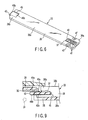
- FIG. 1 shows a portable computer 1 which is an electronic apparatus.
- the portable computer 1 comprises a computer main body 2 and a display unit 3.
- the computer main body 2 has a synthetic resin made housing 4.
- the housing 4 is a flat box comprised of a bottom wall 4a, top wall 4b, right/left side walls 4c, front wall 4d and rear wall (not shown).
- the housing 4 is divided to two sections, that is a lower housing 5 containing the bottom wall 4a and an upper housing 6 containing the top wall 4b.
- the lower housing 5 and upper housing 6 are fastened together by any conventional fastener (e.g., screws).
- the housing 4 accommodates a printed circuit board 7 shown in FIG. 7, a multi-drive in which a CD-ROM drive and a DVD-RAM drive are integrated and a hard disc drive.
- the printed circuit board 7 is loaded with a semiconductor package constituting a CPU and other electronic part.
- the display unit 3 has a display housing 8 and a liquid crystal display panel 9.
- the display housing 8 is a flat box and an end portion thereof is joined to the rear end of the housing 4 rotatably through hinges (not shown).
- the liquid crystal display panel 9 is accommodated in the display housing 8.
- the liquid crystal display panel 9 has a screen 9a for displaying a picture.
- the screen 9a is exposed outside of the display housing 8 through an opening portion 10 formed on the front surface of the display housing 8.
- the display unit 3 is rotatable between its opening position and its closing position. At the opening position, the display unit 3 is erected relative to the housing 4 so as to expose the top wall 4b of the housing 4 and the screen 9a. At the closing position, the display unit 3 is laid over the housing 4 so as to cover the top wall 4b of the housing 4 from above.
- the top wall 4b of the housing 4 has a keyboard supporting portion 11 and a user open area 12.
- the keyboard supporting portion 11 is a recessed area formed in the top surface of the top wall 4b.
- keyboard supporting portion 11 is substantially rectangular and concave in shape to support a keyboard 13.
- the user open area 12 is a region that a user of the portable computer 1 may access voluntarily and is located behind the keyboard 13. This user open area 12 is dented relative to the top surface of the top wall 4b of the housing 4 and extended in the width direction of the housing 4. An end of the user open area 12 is open to a corner portion defined by the top wall 4b and the side wall 4c on the left side, of the housing 4. Likewise, the other end of the user open area 12 is open to a corner portion defined by the top wall 4b and the side wall 4c on the right side, of the housing 4.
- the user open area 12 includes a switch installation portion 14 and a receiving portion 15.
- the switch installation portion 14 is located at a left half of the user open area 12, and covers a switch substrate 16 accommodated in the housing 4 from above.
- a power switch 17 and plural switches 18a, 18b and 18c related to Internet functionality are mounted on the top surface of the switch substrate 16. These switches 17, 18a, 18b and 18c are exposed to the user open area 12 through four through holes 19 made in the switch installation portion 14.
- the receiving portion 15 is located on the right half of the user open area 12.
- the receiving portion 15 is a hollow area formed in the user open area 12, which is generally rectangular in shape extending in the width direction of the housing 4.
- the receiving portion 15 has a horizontal bottom surface 15a.
- a generally concave portion 20 is formed in this bottom surface 15a.
- the concave portion 20 is located at an end along the longitudinal direction of the receiving portion 15.
- a connector substrate 21 is accommodated within the concave portion 20.
- the connector substrate 21 is fixed to the bottom of the concave portion 20 through a screw 22.
- the connector substrate 21 is connected to the printed circuit board 7 through a cable (not shown) and a connector 23 is installed on the top surface of this connector substrate 21.
- the connector 23 includes multiple signal connecting terminals 24 protruded upward. The signal connecting terminals 24 are exposed to the receiving portion 15.
- a pair of boss portions 25 is formed on the bottom of the concave portion 20.
- the boss portions 25 are protruded upward from the bottom of the concave portion 20 and oppose each other across the connector 23.
- Each boss portion 25 has a screw hole 25a as shown in FIG. 8.
- the screw hole 25a is open in a top end surface of the boss portion 25.
- an engaging portion 27 is formed in the other end along the longitudinal direction of the receiving portion 15.
- the engaging portion 27 has an insertion hole 28 and a terminal supporting wall 29.
- the insertion hole 28 is located in a corner defined by the bottom surface 15a and the left side surface, of the receiving portion 15 and open to the inside of the housing 4.
- the terminal supporting wall 29 is integrated with the top wall 4b of the housing 4 and located above the bottom surface 15a of the receiving portion 15.
- the lower surface of the terminal supporting wall 29 is continuous to an opening top edge of the insertion hole 28.
- a sheet-like grounding connecting terminal 30 is attached on the lower surface of the terminal supporting wall 29.
- the grounding connecting terminal 30 is electrically connected to a plating layer (not shown) for shield which covers the inside surface of the housing 4. This plating layer is electrically connected to a ground layer of the printed circuit board 7.
- a cable 31 through which an image signal flows is disposed below the user open area 12.
- the cable 31 electrically connects the printed circuit board 7 with the liquid crystal display panel 9 and passes near the engaging portion 27 of the receiving portion 15.
- the receiving portion 15 in the user open area 12 receives and holds any one of a plurality of operation units 33-35, which are selectively detachable from receiving portion 15.
- These operation units 33-35 include a first operation unit 33 adapted for input of characters, a second operation unit 34 adapted for audio control, and a decoration unit 35.
- the first operation unit 33 comprises a main body 36 and a switch substrate 37.
- the main body 36 is an elongated plate, which may engage the receiving portion 15 and has a first end portion 36a and a second end portion 36b, which are separated in the longitudinal direction. Further, the main body 36 has a lower surface 38a as a first surface and an upper surface 38b as a second surface.
- buttons 40 for, for example, character enlargement, new creation, word/phrase registration, Japanese/English switching and input mode switching are disposed on the upper surface 38b of the main body 36.
- the operation buttons 40 may be depressed by a user and arranged in line in the longitudinal direction of the main body 36.
- the switch substrate 37 is covered with the main body 36.
- the switch substrate 37 includes a plurality of switches (not shown), which are opened/closed by the operation buttons 40 and signal terminals 41.
- the signal terminals 41 are located at the first end portion 36a of the main body 36 and exposed outside through an opening 42 formed in the lower surface 38a of the main body 36.
- the switch substrate 37 has a tongue piece 43.
- the tongue piece 43 protrudes from the second end portion 36b of the main body 36 in the longitudinal direction of the main body 36 and is inserted into the insertion hole 28 of the receiving portion 15 detachably.
- the tongue piece 43 has a first terminal surface 43a generally continuous to the upper surface 38b of the main body 36 and a second terminal surface 43b generally continuous to the lower surface 38a of the main body 36.
- a cutout 45 is formed at a portion corresponding to the second end portion 36b of the lower surface 38a of the main body 36. The cutout 45 is continuous to the tongue piece 43 and the switch substrate 37 is exposed in this cutout 45. Consequently, the second terminal surface 43b of the tongue piece 43 is substantially enlarged.
- First and second ground terminals 46a and 46b are disposed on the first and second terminal surfaces 43a and 43b of the tongue piece 43 respectively.
- the first and second ground terminals 46a and 46b are electrically connected to the ground layer of the switch substrate 37. These first and second ground terminals 46a and 46b are spread into a plane along the first and second terminal surfaces 43a and 43b.
- the area of the second ground terminal 46b is larger than the area of the first ground terminal 46a by that of the cutout 45.
- a pair of screw through holes 47 is formed as fixing portions in the first end portion 36a of the main body 36.
- the screw through holes 47 corresponds to the screw holes 25a in the boss portions 25 and these oppose each other across the signal terminals 41.
- the second operation unit 34 for audio control has the same configuration as the first operation unit 33 except that its switch functions are different. Thus, like reference numerals are attached to the same components as the first operation unit 33 and description thereof is omitted.
- buttons 48 are related to audio control, namely fast forward, reverse, stop, playback and pause for example, are disposed on the upper surface 38b of the main body 36.
- the audio control is selected by depressing operation buttons 48 which are arranged in line in the longitudinal direction of the main body 36.
- the decoration unit 35 has a photo frame 49.
- the photo frame 49 is an elongated plate that may engage the receiving portion 15 and has a flat top surface 50 on which, for example, a photograph or seal may be attached.
- the decoration unit 35 has a function for displaying a photograph or sticker that the user desires.
- the photo frame 49 has a first end portion 49a and a second end portion 49b which are departed in the longitudinal direction.
- a pair of screw through holes 51 is formed as fixing portions in the first end portion 49a of the photo frame 49.
- the screw through holes 51 are spaced in the width direction of the photo frame 49 so as to correspond to the screw holes 25a in the boss portions 25 as discussed with respect to the first operation unit 33 of FIG. 6.
- a tongue piece 52 of the decoration unit 35 is formed at the second end portion 49b of the photo frame 49.
- the tongue piece 52 is protruded from the second end portion 49b of the photo frame 49 in the longitudinal direction of the photo frame 49 and inserted into the insertion hole 28 of the receiving portion 15 detachably.
- the main body 36 of the first operation unit 33 is gripped with the hand and the upper surface 38b on which the operation buttons 40 are disposed is surfaced upward.
- the main body 36 is introduced into the receiving portion 15 in its oblique condition with the tongue piece 43 protruded from the second end portion 36b of the main body 36 held at the head and the tongue piece 43 is inserted into the insertion hole 28 in the engaging portion 27. Consequently, the first ground terminal 46a on the tongue piece 43 makes a contact with the ground connecting terminal 30 located on the engaging portion 27.
- the first operation unit 33 is rotated downward with a contact portion between the first ground terminal 46a and the ground connecting terminal 30 as a fulcrum.
- the first operation unit 33 is pivoted about the second end portion 36b, to be precise, the tongue piece 43.
- the main body 36 is engaged in the receiving portion 15 so that the lower surface 38a of the main body 36 overlaps the bottom surface 15a of the receiving portion 15.
- the first end portion 36a of the main body 36 opposes the connector substrate 21 and the signal terminals 41 exposed on the lower surface 38a of the main body 36 strikes the signal connecting terminals 24 of the connector 23 (see FIG. 7).
- the signal terminals 41 makes a contact with the signal connecting terminals 24 after the first ground terminal 46a of FIG. 9 makes contact with the ground connecting terminal 30.
- the screw through holes 47 of the main body 36 match the screw holes 25a in the boss portions 25.
- the screws 54 are inserted into the screw through holes 47 in the main body 36 (see FIG. 5) and the screws 54 are screwed into the screw holes 25a in the boss portions 25 (see FIG. 8). Consequently, the first end portion 36a of the main body 36 is fixed on the boss portions 25 so that the screws 54 maintains a signal contact between the signal terminals 41 of the main body 36 and the signal connecting terminals 24 of the connector 23 (see FIG. 8).
- the first end portion 36a of the main body 36 receives a downward force.
- the second end portion 36b of the main body 36 at which the tongue piece 43 is located receives an upward force, so that the first ground terminal 46a of FIG. 9 on the tongue piece 43 is pressed against the ground connecting terminal 30. Consequently, the screws 54 also maintain a ground contact between the first ground terminal 46a and the ground connecting terminal 30. Then, installation of the first operation unit 33 is completed.
- the tongue piece 43 When the main body 36 is fixed to the boss portions 25, the tongue piece 43 remains inserted into the insertion hole 28. Thus, the second ground terminal 46b located at the second terminal surface 43b of the tongue piece 43 is exposed within the housing 4 (see FIG. 9) and at the same time, located adjacent to the cable 31 through which an image signal flows (see FIG. 3).
- the user open area 12 of the housing 4 is covered with a top cover 56 that is detachable.
- the top cover 56 is an elongated plate extended in the width direction of the housing 4. This top cover 56 has a front edge portion 57 to be located adjacent the keyboard 13 and a rear edge portion 58 to be located opposite to the front edge portion 57.
- Multiple engaging protrusions 59 are formed to protrude downward at the front edge portion 57 and rear edge portion 58 of the top cover 56.
- the engaging protrusions 59 correspond to multiple engaging holes 60 formed in the peripheral portion of the user open area 12.
- the engaging protrusions 59 are engaged with the engaging holes 60 by sliding in the width direction of the housing 4.
- a lock member 61 is attached to the left end portion of the top cover 56.
- the lock member 61 is hooked by the switch installation portion 14 in the user open area 12, thereby restricting a slide of the top cover 56 in the direction in which the engaging protrusions 59 depart from the engaging holes 60. Consequently, the top cover 56 is held at a specified position of the housing 4.
- the top cover 56 has a first cover portion 63 corresponding to the switch installation portion 14 and a second cover portion 64 corresponding to the receiving portion 15.
- the first cover portion 63 has a power switch button 65 and plural operation buttons 66.
- the power switch button 65 and operation buttons 66 are supported by the first cover portion 63 such that they may be deformed vertically and oppose the power switch 17 and other switches 18a, 18b and 18c.
- the second cover portion 64 has an opening 67.
- the opening 67 is a slit extending in the longitudinal direction of the top cover 56 and located just above the receiving portion 15.
- the opening 67 exposes the operation buttons 40 outside of the housing 4.
- the decoration unit 35 is mounted on the receiving portion 15, the opening 67 exposes a photograph or sticker attached to the photo frame 49 outside of the housing 4.
- the installation/removal work of the first operation unit 33, the second operation unit 34 and the decoration unit 35 onto/from the receiving portion 15 are carried out in a state that the user open area 12 is exposed by removing the top cover 56 from the housing 4.
- the operation buttons 40 of the first operation unit 33 which are mounted on the receiving portion 15 in the housing 4, relate to character input. These operation buttons 40 are exposed through the opening 67 of the top cover 56.
- the second operation unit 34 is mounted on the receiving portion 15 of the housing 4.
- the operation buttons 48 relate to audio control and are exposed through the opening 67 in the top cover 56. Therefore, the operation buttons 40 or 48 may be operated with the finger of the hand like the keyboard 13.
- the decoration unit 35 is mounted on the receiving portion 15 of the housing 4. Consequently, the photo frame 49 on which a photograph or sticker desired by the user is attached may be exposed through the opening 67 in the top cover 56, thereby intensifying the decorative effect of the portable computer 1.
- any one having an optimum function for the application of the portable computer 1 may be selected from the first operation unit 33, the second operation unit 34 and the decoration unit 35 and mounted on the receiving portion 15.
- the operation buttons 40 or 48 may be enlarged or the arrangement interval of the operation buttons 40 or 48 may be enlarged.
- the operability of the operation buttons 40 or 48 is improved thereby usability of the portable computer 1 being improved.
- the first ground terminal 46a of the tongue piece 43 initially comes into contact with the ground connecting terminal 30 of the housing 4.
- the first ground terminal 46a of the first operation unit 33 or the second operation unit 34 makes contact with the ground connecting terminal 30 before the signal terminals 41 makes contact with the signal connecting terminals 24 of the connector 23.
- the second ground terminal 46b located on the second terminal surface 43b of the tongue 43 is exposed inside the housing 4 and located near the cable 31 through which an image signal flows.
- this electromagnetic noise may be led to the ground through the second ground terminal 46b.
- the first end portion of the first or second operation unit is fixed on the receiving portion of the housing by screws.
- the present invention is not limited to this example, but it is permissible to provide the receiving portion with, for example, an elastically deformable latch and fix the first or second operation unit on the receiving portion by hooking this latch on the first end portion.
- the operation unit is not limited to two kinds for the character input and audio but it is permissible to add an operation unit having control keys relating to, for example, Internet connectivity and functionality.
Abstract
Description
Claims (7)
- An electronic apparatus characterized by comprising:a housing (4);a receiving portion (15) provided on the housing (4) and adapted to receive a detachable operation unit (33, 34, 35); anda cover (56) detachably supported in the housing (4), the cover (56) including an opening (67) for exposing the detachable operation unit (33, 34, 35) being received in the receiving portion (15).
- An electronic apparatus according to claim 1, characterized in that the opening (67) of the cover (56) exposes a plurality of operation buttons (40,48) arranged on the operation unit (33, 34).
- An electronic apparatus according to claim 1, characterized in that the receiving portion (15) includes an engaging portion (27) detachably coupled to the operation unit (33, 34, 35).
- An electronic apparatus according to claim 1, characterized in that the receiving portion (15) includes a ground connecting terminal (30) arranged at one end and a signal connecting terminal (24) arranged at other end.
- An electronic apparatus according to claim 4, characterized in that the operation unit (33, 34) includes a ground terminal (46a, 46b) to be connected to the ground connecting terminal (30) and a signal terminal (41) to be connected to the signal connecting terminal (24).
- An electronic apparatus according to claim 5, characterized in that the operation unit (33, 34) includes a first end portion (36a) at which the signal terminal (41) is arranged, and a second end portion (36b) at which the ground terminal (46a, 46b) is arranged.
- An electronic apparatus according to claim 1, characterized in that the operation unit is selected from a plurality of operation units (33, 34, 35).
Applications Claiming Priority (2)
| Application Number | Priority Date | Filing Date | Title |
|---|---|---|---|
| JP2003297703 | 2003-08-21 | ||
| JP2003297703A JP2005070969A (en) | 2003-08-21 | 2003-08-21 | Electronic equipment, and operation unit used for electronic equipment |
Publications (2)
| Publication Number | Publication Date |
|---|---|
| EP1510906A2 true EP1510906A2 (en) | 2005-03-02 |
| EP1510906A3 EP1510906A3 (en) | 2007-01-10 |
Family
ID=34101139
Family Applications (1)
| Application Number | Title | Priority Date | Filing Date |
|---|---|---|---|
| EP04019802A Withdrawn EP1510906A3 (en) | 2003-08-21 | 2004-08-20 | Electronic apparatus with detachable operation unit |
Country Status (4)
| Country | Link |
|---|---|
| US (1) | US20050040972A1 (en) |
| EP (1) | EP1510906A3 (en) |
| JP (1) | JP2005070969A (en) |
| CN (1) | CN1316330C (en) |
Families Citing this family (14)
| Publication number | Priority date | Publication date | Assignee | Title |
|---|---|---|---|---|
| JP4233086B2 (en) * | 2003-03-11 | 2009-03-04 | 株式会社東芝 | Electronics |
| JP2005346185A (en) * | 2004-05-31 | 2005-12-15 | Toshiba Corp | Electronic apparatus |
| JP4533712B2 (en) * | 2004-09-30 | 2010-09-01 | 株式会社東芝 | Electronics |
| JP2006099550A (en) * | 2004-09-30 | 2006-04-13 | Toshiba Corp | Electronic device |
| JP4130672B2 (en) * | 2005-07-29 | 2008-08-06 | 株式会社東芝 | Electronics |
| JP4762002B2 (en) * | 2006-02-27 | 2011-08-31 | 株式会社東芝 | Electronics |
| JP5349825B2 (en) | 2008-03-31 | 2013-11-20 | Hoya株式会社 | Zoom lens system and electronic imaging apparatus using the same |
| US8193466B2 (en) * | 2008-10-24 | 2012-06-05 | Dell Products, Lp | Capacitive input device with removable cover |
| JP2011076490A (en) * | 2009-09-30 | 2011-04-14 | Toshiba Corp | Information processor |
| JP4988029B2 (en) * | 2010-11-30 | 2012-08-01 | 株式会社東芝 | Electronics |
| USD731475S1 (en) * | 2013-11-01 | 2015-06-09 | Hewlett-Packard Development Company, L.P. | Computer |
| USD732524S1 (en) * | 2014-01-29 | 2015-06-23 | Hewlett-Packard Development Company, L.P. | Computer |
| US10212844B2 (en) | 2014-06-20 | 2019-02-19 | Dell Products, Lp | System and method for improving fan life in an information handling system |
| USD820249S1 (en) * | 2017-03-29 | 2018-06-12 | Wipro Limited | Set of biometric sensors for an electronic device |
Citations (3)
| Publication number | Priority date | Publication date | Assignee | Title |
|---|---|---|---|---|
| US5451053A (en) * | 1994-09-09 | 1995-09-19 | Garrido; Fernando P. | Reconfigurable video game controller |
| EP0912081A2 (en) * | 1997-09-25 | 1999-04-28 | Roberts Technologies PLC | Adaptable case and a modular electronic system |
| US20020137477A1 (en) * | 2001-03-21 | 2002-09-26 | Seiko Epson Corporation | Input system for portable terminal, portable terminal, control unit, and input program for portable terminal |
Family Cites Families (19)
| Publication number | Priority date | Publication date | Assignee | Title |
|---|---|---|---|---|
| JPS6343223U (en) * | 1986-09-04 | 1988-03-23 | ||
| US5153589A (en) * | 1988-06-29 | 1992-10-06 | Ncr Corporation | Data processing terminal with removable keyboard module |
| US5335141A (en) * | 1989-06-23 | 1994-08-02 | Kabushiki Kaisha Toshiba | Portable electronic apparatus having a removable keyboard secured to a housing by screws protruding through the bottom wall of the housing |
| JP2763137B2 (en) * | 1989-06-23 | 1998-06-11 | 株式会社東芝 | Keyboard unit and small electronic device equipped with the keyboard unit |
| US5566050A (en) * | 1992-07-17 | 1996-10-15 | Kabushiki Kaisha Toshiba | Compact electronic apparatus having a detachable optional component |
| US5689400A (en) * | 1994-05-31 | 1997-11-18 | Kabushiki Kaisha Toshiba | Portable electronic apparatus including space-saving component mounting features |
| JP3080860B2 (en) * | 1995-05-30 | 2000-08-28 | 科学技術振興事業団 | Dry etching method |
| US5805861A (en) * | 1995-08-29 | 1998-09-08 | Unisys Corporation | Method of stabilizing component and net names of integrated circuits in electronic design automation systems |
| JP3382073B2 (en) * | 1995-09-19 | 2003-03-04 | 株式会社東芝 | Portable electronic devices |
| DE29604776U1 (en) * | 1996-03-14 | 1996-08-08 | Siemens Nixdorf Inf Syst | Front cover for a computer case |
| US6125040A (en) * | 1998-02-27 | 2000-09-26 | Fujitsu Limited | Information processing apparatus and hook mechanism applicable to the apparatus |
| JPH11249789A (en) * | 1998-03-02 | 1999-09-17 | Toshiba Tec Corp | Keyboard device |
| JPH11282608A (en) * | 1998-03-31 | 1999-10-15 | Fujitsu Takamisawa Component Ltd | Keyboard unit and portable information device provided with the keyboard unit |
| IT1305960B1 (en) * | 1998-05-11 | 2001-05-21 | Esaote Spa | STRUCTURE OF MAGNET IN PARTICULAR FOR MACHINES FOR IMAGE DETECTION IN NUCLEAR MAGNETIC RESONANCE. |
| US6394300B1 (en) * | 2000-04-17 | 2002-05-28 | Daniel F. Bosy | Lock for compartment cover |
| CN2480893Y (en) * | 2001-01-31 | 2002-03-06 | 达方电子股份有限公司 | Demountable keyboard assembly fastener |
| JP2003015776A (en) * | 2001-06-28 | 2003-01-17 | Toshiba Corp | Electronic equipment and component mounting method for electronic equipment |
| US6937465B2 (en) * | 2002-01-31 | 2005-08-30 | Samsung Electronics Co., Ltd. | Portable computer having a latch apparatus |
| JP2005070970A (en) * | 2003-08-21 | 2005-03-17 | Toshiba Corp | Electronic equipment |
-
2003
- 2003-08-21 JP JP2003297703A patent/JP2005070969A/en active Pending
-
2004
- 2004-04-26 US US10/832,876 patent/US20050040972A1/en not_active Abandoned
- 2004-08-20 EP EP04019802A patent/EP1510906A3/en not_active Withdrawn
- 2004-08-20 CN CNB200410057607XA patent/CN1316330C/en not_active Expired - Fee Related
Patent Citations (3)
| Publication number | Priority date | Publication date | Assignee | Title |
|---|---|---|---|---|
| US5451053A (en) * | 1994-09-09 | 1995-09-19 | Garrido; Fernando P. | Reconfigurable video game controller |
| EP0912081A2 (en) * | 1997-09-25 | 1999-04-28 | Roberts Technologies PLC | Adaptable case and a modular electronic system |
| US20020137477A1 (en) * | 2001-03-21 | 2002-09-26 | Seiko Epson Corporation | Input system for portable terminal, portable terminal, control unit, and input program for portable terminal |
Also Published As
| Publication number | Publication date |
|---|---|
| CN1316330C (en) | 2007-05-16 |
| JP2005070969A (en) | 2005-03-17 |
| CN1584775A (en) | 2005-02-23 |
| EP1510906A3 (en) | 2007-01-10 |
| US20050040972A1 (en) | 2005-02-24 |
Similar Documents
| Publication | Publication Date | Title |
|---|---|---|
| EP1510906A2 (en) | Electronic apparatus with detachable operation unit | |
| US6053586A (en) | Computer access panel having a biased cover latching mechanism and method | |
| US6198626B1 (en) | Portable apparatus removable top cover covering functional component | |
| US5455737A (en) | Electronic apparatus with storing section for storing detachable unit including groove holding strip-like function label | |
| US5825614A (en) | Compact personal computer with LCD monitor | |
| US5255154A (en) | Portable electronic apparatus with a latch mechanism including an interlock | |
| US5574625A (en) | Portable information processing apparatus having multiple rotatable port covers | |
| US6972946B2 (en) | Electronic apparatus having a housing | |
| JP3963785B2 (en) | Information processing apparatus and printed circuit board | |
| US5251096A (en) | Portable electronic apparatus | |
| JP2008141139A (en) | Electronic apparatus, flexible substrate, and substrate-fixing member | |
| JP2001067146A (en) | Lock device for extended unit of computer | |
| JP2002341967A (en) | Portable electronic equipment | |
| JP2008140342A (en) | Electronic equipment and component | |
| JPH10307642A (en) | Electronic equipment | |
| US7149079B2 (en) | Electronic apparatus having keyboard | |
| JP3394818B2 (en) | Portable electronic devices | |
| JP2007048326A (en) | Information processor and printed board | |
| JP2000357027A (en) | Information processor | |
| JPH03173077A (en) | Connector device | |
| JP2003216278A (en) | Electronic device | |
| WO1999064949A1 (en) | Folding electronic apparatus | |
| JP3124122B2 (en) | Small electronic equipment | |
| JPH11184559A (en) | Portable information equipment | |
| JPH0728559A (en) | Portable electronic apparatus |
Legal Events
| Date | Code | Title | Description |
|---|---|---|---|
| PUAI | Public reference made under article 153(3) epc to a published international application that has entered the european phase |
Free format text: ORIGINAL CODE: 0009012 |
|
| 17P | Request for examination filed |
Effective date: 20040820 |
|
| AK | Designated contracting states |
Kind code of ref document: A2 Designated state(s): AT BE BG CH CY CZ DE DK EE ES FI FR GB GR HU IE IT LI LU MC NL PL PT RO SE SI SK TR |
|
| AX | Request for extension of the european patent |
Extension state: AL HR LT LV MK |
|
| PUAL | Search report despatched |
Free format text: ORIGINAL CODE: 0009013 |
|
| AK | Designated contracting states |
Kind code of ref document: A3 Designated state(s): AT BE BG CH CY CZ DE DK EE ES FI FR GB GR HU IE IT LI LU MC NL PL PT RO SE SI SK TR |
|
| AX | Request for extension of the european patent |
Extension state: AL HR LT LV MK |
|
| 17Q | First examination report despatched |
Effective date: 20070227 |
|
| AKX | Designation fees paid |
Designated state(s): DE FR GB |
|
| STAA | Information on the status of an ep patent application or granted ep patent |
Free format text: STATUS: THE APPLICATION IS DEEMED TO BE WITHDRAWN |
|
| 18D | Application deemed to be withdrawn |
Effective date: 20100302 |