EP1512807A1 - Element für einen Fussbodenbelag mit einer dünnen Mittelschicht - Google Patents
Element für einen Fussbodenbelag mit einer dünnen Mittelschicht Download PDFInfo
- Publication number
- EP1512807A1 EP1512807A1 EP04021142A EP04021142A EP1512807A1 EP 1512807 A1 EP1512807 A1 EP 1512807A1 EP 04021142 A EP04021142 A EP 04021142A EP 04021142 A EP04021142 A EP 04021142A EP 1512807 A1 EP1512807 A1 EP 1512807A1
- Authority
- EP
- European Patent Office
- Prior art keywords
- middle layer
- thickness
- groove
- spring
- element according
- Prior art date
- Legal status (The legal status is an assumption and is not a legal conclusion. Google has not performed a legal analysis and makes no representation as to the accuracy of the status listed.)
- Granted
Links
Images

Classifications
-
- E—FIXED CONSTRUCTIONS
- E04—BUILDING
- E04F—FINISHING WORK ON BUILDINGS, e.g. STAIRS, FLOORS
- E04F15/00—Flooring
- E04F15/02—Flooring or floor layers composed of a number of similar elements
-
- E—FIXED CONSTRUCTIONS
- E04—BUILDING
- E04F—FINISHING WORK ON BUILDINGS, e.g. STAIRS, FLOORS
- E04F2201/00—Joining sheets or plates or panels
- E04F2201/01—Joining sheets, plates or panels with edges in abutting relationship
- E04F2201/0153—Joining sheets, plates or panels with edges in abutting relationship by rotating the sheets, plates or panels around an axis which is parallel to the abutting edges, possibly combined with a sliding movement
-
- E—FIXED CONSTRUCTIONS
- E04—BUILDING
- E04F—FINISHING WORK ON BUILDINGS, e.g. STAIRS, FLOORS
- E04F2201/00—Joining sheets or plates or panels
- E04F2201/03—Undercut connections, e.g. using undercut tongues or grooves
Definitions
- the invention relates to an element for a floor covering with a thin middle layer of rigid material, in particular with a middle layer of a wood material, having the coupling profiles for coupling further, the same elements.
- the Coupling profiles are shaped in the manner of a tongue and groove joint and two Long edges of the element and possibly worked out at two transverse edges.
- the coupling profiles allow a permanent assembly of the elements without additional Aids such as e.g. Glue.
- the execution of the coupling profiles considered in Specifically, the material properties of the middle layer material to be used.
- Glueless coupling profiles can be easily divided into two main groups. To the one in so-called “click” connections, in which in addition to the known Coupling profiles are still provided elastic locking profiles and / or the coupling profile is designed to be elastic. On the other hand, there are elements known, which can be added by pivoting and thereby by the positive engagement the coupling profiles during pivoting no elastic movement of the coupling profile need.
- Parquet floors have elements with glueless coupling profiles as parquet floors widespread found.
- Parquet floors are characterized Middle layers of solid wood, on which also cover layers and Gegenzug harshen are glued.
- the cover layers and counter layers are of their own Strengths and material properties such that they work out a Coupling profiles or portions of a coupling profile are suitable. Therefore, it stands also with parquet floors, the entire element thickness to work out the glueless Coupling profiles available.
- Parquet floors with glueless coupling profiles are made from 20mm down to 13mm.
- cover layers have low strength have found widespread use as finished floors with glueless coupling profiles. Such finished floor coverings also have middle layers on top layers and counter layers are glued on.
- the cover layers can be made of a variety of Materials such. As cork, linoleum, rubber, veneer or other Coverings exist. As backing layers can be simple papers and / or materials such as cork, cardboard, natural and artificial insulation boards, etc. are used. In contrast to the two aforementioned types laminate flooring and parquet floors can not here the total thickness of the element for working out the coupling profiles be used.
- Both the outer layers and the counter layers are due to their material properties, especially because of the low density and low strength properties so that they do not work out the coupling profiles or a portion of the coupling profiles are suitable.
- the for middle classes of finished floor coverings with low-strength cover layers are used Wood materials can therefore in contrast to laminate floors or parquet on the Cover and the counter layers no additional strength and additional gain in strength reach for the coupling profile.
- this type requires floor coverings Middle layers that allow a sufficient connection, preferably Bonding to allow for covering and backing layers with the middle layer.
- a surface finish with the associated strength gain of Middle layer such as e.g. This is not possible with laminate floors.
- the strength of the profile can not be reduced arbitrarily, as a coupling profile on the one hand must be able to be worked out by usual processing methods and on the other hand to ensure sufficient strength of the verkuppelten elements got to.
- the minimum total thickness of the floor element is first determined by the middle layer, from which the coupling profiles are worked out, and only then from the Strengths of the outer layer and the Gegenzug harsh determined.
- the strengths of the deck and Counter layers can vary depending on the design, the middle layer with the machined coupling profile is according to the present state of the art of 7 to 10mm made.
- the dimensioning of the coupling profiles is based on the material-specific strength values of the middle class and at the disposal standing middle layer thickness. In the aforementioned construction arise existing State of the art Total thicknesses of a floor element of 10 to 15mm.
- the stability of a coupling profile can only take into account the superimposed Forces acting on the laid floor coverings are assessed.
- the in horizontal Directional shrinkage stresses can not be considered in isolation, because by simultaneously acting dynamic loading, e.g. Committing, vertical Movements induced in the verkuppelten profile.
- the load capacity of a Coupling profile decreases sharply when the superimposed vertical movements of the laid floor covering lead to movements within the coupling profile and / or for splitting the middle layer and thereby the functional failure of the coupling profile or a portion of the coupling profile lead.
- a mere scale reduction of the coupling profile also leads to the accuracy with which the elements must be pivoted together increases.
- the known element has at least one first longitudinal edge with a groove on, which has a long groove cheek and a short groove cheek, wherein the groove is formed is that when installed it receives a spring of a second element, so that the two connected elements against a vertical movement and against a horizontal separation are secured.
- such an element now has a middle layer that has a thickness S of up to 6 mm, in which the short groove cheek substantially parallel to the top the element is arranged, and the distance between the bottom of the short Groove cheek and the top of the middle layer to 23-24% of the strength of the middle layer (2).
- the long groove cheek Angled relative to the underside of the middle layer, wherein a first section, which runs below the short groove cheek, inclined from the bottom of the groove to the bottom , a second section following the first section is essentially parallel to the bottom runs, a third section, which is parallel to the second section runs and where a fourth section of the to the free end of the long Nutwange connects to the third section, rises to the top of the element, however, has a maximum strength of 75% of the thickness S of the middle layer.
- the Thickness of the second portion of the long groove cheek is 33% of the thickness S of the middle layer of the element according to the invention.
- the spring has a strength of up 44%, based on the thickness S of the middle layer, wherein the first contact surface 12a between spring and short groove cheek a maximum of 30% of the total length of the free end the spring is, and wherein the second contact surface between spring and second Section of the long groove cheek maximum 50% of the second section of the long groove cheek is.
- an angle ⁇ which is bounded by a line and a straight line up to approx. Is 16 °
- a distance 24a which corresponds to the width of the fourth section, in relation to the distance that extends from the intersection of the abutting surface with the top of the Spring to the transition of defined sections of the underside of the spring (see Embodiment), in the ratio of 1: 2 stands.
- Fig. 1 shows the structure of the longitudinal edge of an element 1 of a floor covering.
- the Middle layer 2 is made of HDF material.
- a decorative layer D is applied on top 4 of the middle layer .
- a Gegenzug G is applied on the bottom 6 of the middle layer 2 .
- the floor element 1 is in the installed state on the Floor up.
- a groove 10 is incorporated in a side surface 8 of the middle layer 2.
- a complementary spring 3 is worked out from the corresponding side edge 8 .
- This groove 10 is formed as shown in FIG. 1 so that they are in the installed state
- Spring 3 receives a second element, so that the two connected elements secured against vertical movement and against horizontal pulling apart are.
- the groove 10 and the spring 3 are each incorporated in the longitudinal edges of the element 1.
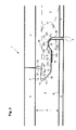
- Fig. 2 shows a comparable arrangement, but for a transverse edge of a Element.
- the thus designed element has a middle layer thickness S of 6 mm, wherein the Thickness can be reduced to 5 mm.
- the groove 10 has a short groove cheek 12th on, which runs parallel to the top 4.
- the strength of this groove cheek 12 is based on the strength S of the middle class 23 to 24% of the strength S.
- a first end of the short Nutwange 12 ends at the groove bottom 14.
- a second end of the short groove cheek 12 ends or in the side surface 8.
- the groove base 14 extends perpendicularly to the top side 4 over 11 to 12% of the thickness S of the middle layer 2.
- At the lower end of the groove bottom 14 sets the long groove cheek 16, which extends beyond the short groove cheek 12 out to a free end 18 extends.
- a first portion 20 of the long groove cheek 16 extends directed from the bottom of the groove 14 to the bottom 6 and ends at the second portion 22 a, the runs parallel to the bottom 6.
- the second section 22a with a thickness of 33% of Middle layer thickness S passes over into a weaker third section 22b, whose Thickness is 30% of the middle layer thickness S.
- the corresponding with the groove 10 Spring 3 is located after the joining of two complementary elements 1 on the stronger second section 22a.
- the weaker third section 22b has no contact with Spring 3, it therefore allows a simpler moving second elements 1 parallel to its longitudinal axis.
- the fourth portion 24 has a maximum thickness, the 75% of the strength S does not exceed the middle class.
- the distance from the end of the third Section 22b to the free end of the long groove cheek 16, is used as the width 24a of fourth section 24.
- the element 1 has at the side edges 8 abutting surfaces 26. Extend the abutment surfaces each from the short groove cheek 12 to the top 4 of the element 2 and of the top 28 of the spring 3 to the top 4 of the element 1.
- the abutting surfaces 26 are with corresponding or nested elements 1 facing each other, they but not always straight. You can have recesses or in one Be spaced from each other.
- the spring 3 extends with a freely projecting part 5 of the abutment surface 26 of the Element 1 to a free end 30, which faces the groove bottom 14.
- the first Bearing surface 12a may be arranged in a plane with the top 28 or in Distance to go.
- Below the free end 30, the underside 32 of the runs Spring 3 substantially corresponding to the sections 1 to 4 of the long groove cheek 16.
- the length of the second abutment surface 22a between the spring 3 and the second portion 22a of the long groove cheek is about 30% of the length of the second portion the long groove cheek.
- the portion of the bottom 32, the sections 22 and 22b spans, be formed just so that in the joined state the Bottom 32 abuts the portion 22 a, the portion 22 b but has a distance.
- the fourth portion 24 of the longer groove cheek 16 is connected to the free end 18 in one Recess 34 recorded.
- the recess 34 is bounded by a lower Abutting surface 36 and through portions of the underside 32 of the spring 3.
- the underside 32 is over the fourth section 24 of the longer groove cheek into three sections 32a, 32b and Shared 32c.
- the portion 32a extends from the bottom 32 of the spring 3 to the top 4 of the element 1. This section 32a is followed by the section 32b which runs approximately horizontally. Section 32b ends with its other end at the section 32c, which is inclined down to the bottom 6 of the element 1 and at the lower abutment surface 36 ends.
- the overall length of the spring 3 extends from the lower abutment surface 36 to the free end 30 of the spring.
- An angle ⁇ is bounded by a line 38 that the top 28 of the spring 3 horizontally and parallel to the top 4 of the Elements 1 continues and from a straight line 24b, extending from the interface of the line 38 with the abutment surface 26 up to the interface between the section 32a and the Section 32 b extends.
- the angle ⁇ is at a longitudinal edge profile 13 ° and at a transverse or end edge profile 16 ° (see Fig. 2).
- the width 24a of the fourth section 24 is in relation to the line 24b in the ratio of 1: 2.
- the design of the Width 24a depends on the shear strength of the middle layer and the load parameters the laid surfaces.
- the spring 3 has in its free section a thickness of 43 to 44%, based on the Strength of the middle layer of the element, on.
- a thickness of 43 to 44% based on the Strength of the middle layer of the element, on.
- the length of the first contact surface 12a is between spring and shorter Groove cheek about 15% of the strength of the middle class.
- the above design rules for the spring, its strength and the relationship of the contact surfaces to each other ensures that the connection is easy to produce by pivoting and holds reliably.
- the design rules are based on uncoated HDF boards to be glued with dispersion adhesives with densities of 850 to 950 kg / m 2 with typical transverse tensile strengths of approx. 1.4 to 1.8 N / mm 2 , with typical bending strengths of 40 to 50 N / mm 2 and on usual loads of the laid surface in living space usual size of up to 70 m 2 .
- the total thickness of the floor element may exceed 6 mm if a decorative Layer D on the top 4 and / or a Gegenzug harsh on the bottom 6 of the middle layer 2 is applied, and these layers on the strength of a Go out decor paper. For example, cork and linoleum become stronger Layers of about 2 mm processed.
- bearing surfaces 12a and 22a are sufficient for a vertical Positioning of the tongue and groove connection.
- the in Fig. 2 in the illustration of the transverse edge profile reduced bearing surfaces take into account a move the verkuppelten transverse edge profile, which is necessary during assembly.
- the angle ⁇ in conjunction with the measure 24a and the consequent measure 24b the material properties of the middle layer and the superimposed loads of a laid floor. Your exact vote and your relationships to each other, as well the absolute dimension 24a ensure an optimal match between the material properties, the middle layer thickness and the loads of the coupling profile through a laid floor.
- An element according to the invention is usually rectangular in shape. It has the above-described Groove on a longitudinal edge (Fig.1) on. After a usual execution is in each case one longitudinal edge with the above-described groove and a further longitudinal edge with executed the complementary spring. In addition, it has a prescribed groove a transverse edge ( Figure 2). It is in each case a transverse edge with the above-described groove and another cross-edge provided with the complementary spring.
Landscapes
- Engineering & Computer Science (AREA)
- Architecture (AREA)
- Civil Engineering (AREA)
- Structural Engineering (AREA)
- Floor Finish (AREA)
- Materials For Medical Uses (AREA)
Applications Claiming Priority (4)
| Application Number | Priority Date | Filing Date | Title |
|---|---|---|---|
| DE20313942 | 2003-09-05 | ||
| DE20313942U | 2003-09-05 | ||
| DE10349525 | 2003-10-22 | ||
| DE10349525A DE10349525A1 (de) | 2003-09-05 | 2003-10-22 | Element für einen Fußbodenbelag mit einer dünnen Mittelschicht |
Publications (3)
| Publication Number | Publication Date |
|---|---|
| EP1512807A1 true EP1512807A1 (de) | 2005-03-09 |
| EP1512807B1 EP1512807B1 (de) | 2008-05-07 |
| EP1512807B9 EP1512807B9 (de) | 2008-09-10 |
Family
ID=34137330
Family Applications (1)
| Application Number | Title | Priority Date | Filing Date |
|---|---|---|---|
| EP04021142A Not-in-force EP1512807B9 (de) | 2003-09-05 | 2004-09-06 | Element für einen Fussbodenbelag mit einer dünnen Mittelschicht |
Country Status (3)
| Country | Link |
|---|---|
| EP (1) | EP1512807B9 (es) |
| AT (1) | ATE394559T1 (es) |
| DE (1) | DE502004007033D1 (es) |
Cited By (1)
| Publication number | Priority date | Publication date | Assignee | Title |
|---|---|---|---|---|
| EP3216941A1 (de) * | 2016-03-10 | 2017-09-13 | tilo GmbH | Fussbodenbelag |
Citations (6)
| Publication number | Priority date | Publication date | Assignee | Title |
|---|---|---|---|---|
| AT321529B (de) * | 1971-11-29 | 1975-04-10 | Heinrich Hebgen | Formschlüssige Fugenverbindung von plattenförmigen Bauelementen |
| DE9109031U1 (es) * | 1991-07-22 | 1991-12-12 | Baustoff- Und Holzhandel Martin Wimmer, 8221 Waging, De | |
| WO1997047834A1 (en) * | 1996-06-11 | 1997-12-18 | Unilin Beheer B.V. | Floor covering, consisting of hard floor panels and method for manufacturing such floor panels |
| WO1999066151A1 (en) * | 1998-06-03 | 1999-12-23 | Välinge Aluminium AB | Locking system and flooring board |
| WO2000066856A1 (en) * | 1999-04-30 | 2000-11-09 | Välinge Aluminium AB | Locking system, floorboard comprising such a locking system, as well as method for making floorboards |
| WO2001053628A1 (en) * | 2000-01-24 | 2001-07-26 | VäLINGE ALUMINUM AB | Locking system for mechanical joining of floorboards and method for production thereof |
-
2004
- 2004-09-06 DE DE502004007033T patent/DE502004007033D1/de active Active
- 2004-09-06 AT AT04021142T patent/ATE394559T1/de active
- 2004-09-06 EP EP04021142A patent/EP1512807B9/de not_active Not-in-force
Patent Citations (6)
| Publication number | Priority date | Publication date | Assignee | Title |
|---|---|---|---|---|
| AT321529B (de) * | 1971-11-29 | 1975-04-10 | Heinrich Hebgen | Formschlüssige Fugenverbindung von plattenförmigen Bauelementen |
| DE9109031U1 (es) * | 1991-07-22 | 1991-12-12 | Baustoff- Und Holzhandel Martin Wimmer, 8221 Waging, De | |
| WO1997047834A1 (en) * | 1996-06-11 | 1997-12-18 | Unilin Beheer B.V. | Floor covering, consisting of hard floor panels and method for manufacturing such floor panels |
| WO1999066151A1 (en) * | 1998-06-03 | 1999-12-23 | Välinge Aluminium AB | Locking system and flooring board |
| WO2000066856A1 (en) * | 1999-04-30 | 2000-11-09 | Välinge Aluminium AB | Locking system, floorboard comprising such a locking system, as well as method for making floorboards |
| WO2001053628A1 (en) * | 2000-01-24 | 2001-07-26 | VäLINGE ALUMINUM AB | Locking system for mechanical joining of floorboards and method for production thereof |
Cited By (1)
| Publication number | Priority date | Publication date | Assignee | Title |
|---|---|---|---|---|
| EP3216941A1 (de) * | 2016-03-10 | 2017-09-13 | tilo GmbH | Fussbodenbelag |
Also Published As
| Publication number | Publication date |
|---|---|
| EP1512807B1 (de) | 2008-05-07 |
| EP1512807B9 (de) | 2008-09-10 |
| ATE394559T1 (de) | 2008-05-15 |
| DE502004007033D1 (de) | 2008-06-19 |
Similar Documents
| Publication | Publication Date | Title |
|---|---|---|
| DE69926608T2 (de) | Fussbodensystem umfassend Fussbodenplatten mit Führungsmitteln | |
| EP1350904B2 (de) | Fussbodendielen | |
| DE602004010914T3 (de) | Satz von Fussbodenpaneelen | |
| DE10159284B4 (de) | Gebäudeplatte, insbesondere Bodenpaneel | |
| DE69434094T2 (de) | Holz- oder Laminatfussbodensystem mit einer Vielzahl von Fussbodenpaneelen | |
| DE10206877B4 (de) | Paneel, insbesondere Fussbodenpaneel | |
| DE69912950T3 (de) | Bodenplatte | |
| DE10101202B4 (de) | Parkettplatte | |
| DE202006020940U1 (de) | Mechanisches Verriegelungssystem für Bodenpaneele | |
| EP1922455B1 (de) | Paneel zum mechanischen Verbinden mit einem weiteren Paneel durch Verschwenken | |
| WO2002001018A1 (de) | Fussbodenplatte | |
| EP1400641A2 (de) | Paneele mit Verbindungsklammer | |
| DE60312212T2 (de) | Bodenplatte und bodenabdeckung für elastischen boden | |
| EP1203855A2 (de) | Plattenelement | |
| DE10013684A1 (de) | Verbindungssystem für Platten | |
| EP3202567A1 (de) | Bauelement aus holz-beton-verbund sowie verfahren zu dessen herstellung | |
| EP1700966A1 (de) | Flachdübelverbinder zur Fixierung nebeneinander angeordneter lattenförmiger Holzelemente | |
| DE202004021867U1 (de) | Mechanische Verriegelung für Bodenpaneele | |
| EP1512807B1 (de) | Element für einen Fussbodenbelag mit einer dünnen Mittelschicht | |
| DE10154767B4 (de) | Fussbodenpaneel | |
| DE10349525A1 (de) | Element für einen Fußbodenbelag mit einer dünnen Mittelschicht | |
| DE102016009103B4 (de) | Mehrteilige Ankerprofile | |
| DE4123682A1 (de) | Wand-, decken- oder balkenelement aus verleimten holzeinzelelementen sowie daraus hergestellte vollholzwand | |
| DE10052490B4 (de) | Hohlraumabdeckelement sowie Verfahren zur Herstellung von Hohlraumabdeckelementen | |
| WO2000074911A1 (de) | Parkettlamelle, deren verwendung zur herstellung eines paneels oder parkettelementes, sowie hieraus hergestelltes parkettelement und verfahren zur herstellung einer parkettlamelle |
Legal Events
| Date | Code | Title | Description |
|---|---|---|---|
| PUAI | Public reference made under article 153(3) epc to a published international application that has entered the european phase |
Free format text: ORIGINAL CODE: 0009012 |
|
| AK | Designated contracting states |
Kind code of ref document: A1 Designated state(s): AT BE BG CH CY CZ DE DK EE ES FI FR GB GR HU IE IT LI LU MC NL PL PT RO SE SI SK TR |
|
| AX | Request for extension of the european patent |
Extension state: AL HR LT LV MK |
|
| 17P | Request for examination filed |
Effective date: 20050829 |
|
| AKX | Designation fees paid |
Designated state(s): AT BE BG CH CY CZ DE DK EE ES FI FR GB GR HU IE IT LI LU MC NL PL PT RO SE SI SK TR |
|
| 17Q | First examination report despatched |
Effective date: 20061124 |
|
| GRAP | Despatch of communication of intention to grant a patent |
Free format text: ORIGINAL CODE: EPIDOSNIGR1 |
|
| GRAS | Grant fee paid |
Free format text: ORIGINAL CODE: EPIDOSNIGR3 |
|
| GRAA | (expected) grant |
Free format text: ORIGINAL CODE: 0009210 |
|
| AK | Designated contracting states |
Kind code of ref document: B1 Designated state(s): AT BE BG CH CY CZ DE DK EE ES FI FR GB GR HU IE IT LI LU MC NL PL PT RO SE SI SK TR |
|
| REG | Reference to a national code |
Ref country code: GB Ref legal event code: FG4D Free format text: NOT ENGLISH |
|
| REG | Reference to a national code |
Ref country code: CH Ref legal event code: EP Ref country code: CH Ref legal event code: NV Representative=s name: PATENTANWALT DIPL. ING. WOLFGANG HEISEL |
|
| REG | Reference to a national code |
Ref country code: IE Ref legal event code: FG4D Free format text: LANGUAGE OF EP DOCUMENT: GERMAN |
|
| REF | Corresponds to: |
Ref document number: 502004007033 Country of ref document: DE Date of ref document: 20080619 Kind code of ref document: P |
|
| PG25 | Lapsed in a contracting state [announced via postgrant information from national office to epo] |
Ref country code: SI Free format text: LAPSE BECAUSE OF FAILURE TO SUBMIT A TRANSLATION OF THE DESCRIPTION OR TO PAY THE FEE WITHIN THE PRESCRIBED TIME-LIMIT Effective date: 20080507 |
|
| PG25 | Lapsed in a contracting state [announced via postgrant information from national office to epo] |
Ref country code: NL Free format text: LAPSE BECAUSE OF FAILURE TO SUBMIT A TRANSLATION OF THE DESCRIPTION OR TO PAY THE FEE WITHIN THE PRESCRIBED TIME-LIMIT Effective date: 20080507 Ref country code: FI Free format text: LAPSE BECAUSE OF FAILURE TO SUBMIT A TRANSLATION OF THE DESCRIPTION OR TO PAY THE FEE WITHIN THE PRESCRIBED TIME-LIMIT Effective date: 20080507 |
|
| REG | Reference to a national code |
Ref country code: ES Ref legal event code: FG2A Ref document number: 2305633 Country of ref document: ES Kind code of ref document: T3 |
|
| NLV1 | Nl: lapsed or annulled due to failure to fulfill the requirements of art. 29p and 29m of the patents act | ||
| PG25 | Lapsed in a contracting state [announced via postgrant information from national office to epo] |
Ref country code: PL Free format text: LAPSE BECAUSE OF FAILURE TO SUBMIT A TRANSLATION OF THE DESCRIPTION OR TO PAY THE FEE WITHIN THE PRESCRIBED TIME-LIMIT Effective date: 20080507 |
|
| REG | Reference to a national code |
Ref country code: IE Ref legal event code: FD4D |
|
| PG25 | Lapsed in a contracting state [announced via postgrant information from national office to epo] |
Ref country code: SE Free format text: LAPSE BECAUSE OF FAILURE TO SUBMIT A TRANSLATION OF THE DESCRIPTION OR TO PAY THE FEE WITHIN THE PRESCRIBED TIME-LIMIT Effective date: 20080807 Ref country code: PT Free format text: LAPSE BECAUSE OF FAILURE TO SUBMIT A TRANSLATION OF THE DESCRIPTION OR TO PAY THE FEE WITHIN THE PRESCRIBED TIME-LIMIT Effective date: 20081007 Ref country code: IE Free format text: LAPSE BECAUSE OF FAILURE TO SUBMIT A TRANSLATION OF THE DESCRIPTION OR TO PAY THE FEE WITHIN THE PRESCRIBED TIME-LIMIT Effective date: 20080507 Ref country code: CZ Free format text: LAPSE BECAUSE OF FAILURE TO SUBMIT A TRANSLATION OF THE DESCRIPTION OR TO PAY THE FEE WITHIN THE PRESCRIBED TIME-LIMIT Effective date: 20080507 Ref country code: DK Free format text: LAPSE BECAUSE OF FAILURE TO SUBMIT A TRANSLATION OF THE DESCRIPTION OR TO PAY THE FEE WITHIN THE PRESCRIBED TIME-LIMIT Effective date: 20080507 |
|
| PG25 | Lapsed in a contracting state [announced via postgrant information from national office to epo] |
Ref country code: SK Free format text: LAPSE BECAUSE OF FAILURE TO SUBMIT A TRANSLATION OF THE DESCRIPTION OR TO PAY THE FEE WITHIN THE PRESCRIBED TIME-LIMIT Effective date: 20080507 Ref country code: RO Free format text: LAPSE BECAUSE OF FAILURE TO SUBMIT A TRANSLATION OF THE DESCRIPTION OR TO PAY THE FEE WITHIN THE PRESCRIBED TIME-LIMIT Effective date: 20080507 |
|
| PLBE | No opposition filed within time limit |
Free format text: ORIGINAL CODE: 0009261 |
|
| STAA | Information on the status of an ep patent application or granted ep patent |
Free format text: STATUS: NO OPPOSITION FILED WITHIN TIME LIMIT |
|
| BERE | Be: lapsed |
Owner name: TILO GMBH Effective date: 20080930 |
|
| 26N | No opposition filed |
Effective date: 20090210 |
|
| PG25 | Lapsed in a contracting state [announced via postgrant information from national office to epo] |
Ref country code: EE Free format text: LAPSE BECAUSE OF FAILURE TO SUBMIT A TRANSLATION OF THE DESCRIPTION OR TO PAY THE FEE WITHIN THE PRESCRIBED TIME-LIMIT Effective date: 20080507 Ref country code: BG Free format text: LAPSE BECAUSE OF FAILURE TO SUBMIT A TRANSLATION OF THE DESCRIPTION OR TO PAY THE FEE WITHIN THE PRESCRIBED TIME-LIMIT Effective date: 20080807 Ref country code: MC Free format text: LAPSE BECAUSE OF NON-PAYMENT OF DUE FEES Effective date: 20080930 |
|
| REG | Reference to a national code |
Ref country code: CH Ref legal event code: PCAR Free format text: PATENTANWALT DIPL.-ING. (UNI.) WOLFGANG HEISEL;HAUPTSTRASSE 14;8280 KREUZLINGEN (CH) |
|
| GBPC | Gb: european patent ceased through non-payment of renewal fee |
Effective date: 20080906 |
|
| REG | Reference to a national code |
Ref country code: FR Ref legal event code: ST Effective date: 20090529 |
|
| PG25 | Lapsed in a contracting state [announced via postgrant information from national office to epo] |
Ref country code: BE Free format text: LAPSE BECAUSE OF NON-PAYMENT OF DUE FEES Effective date: 20080930 |
|
| PG25 | Lapsed in a contracting state [announced via postgrant information from national office to epo] |
Ref country code: FR Free format text: LAPSE BECAUSE OF NON-PAYMENT OF DUE FEES Effective date: 20080930 |
|
| PG25 | Lapsed in a contracting state [announced via postgrant information from national office to epo] |
Ref country code: GB Free format text: LAPSE BECAUSE OF NON-PAYMENT OF DUE FEES Effective date: 20080906 |
|
| PG25 | Lapsed in a contracting state [announced via postgrant information from national office to epo] |
Ref country code: CY Free format text: LAPSE BECAUSE OF FAILURE TO SUBMIT A TRANSLATION OF THE DESCRIPTION OR TO PAY THE FEE WITHIN THE PRESCRIBED TIME-LIMIT Effective date: 20080507 Ref country code: HU Free format text: LAPSE BECAUSE OF FAILURE TO SUBMIT A TRANSLATION OF THE DESCRIPTION OR TO PAY THE FEE WITHIN THE PRESCRIBED TIME-LIMIT Effective date: 20081108 Ref country code: LU Free format text: LAPSE BECAUSE OF NON-PAYMENT OF DUE FEES Effective date: 20080906 |
|
| PG25 | Lapsed in a contracting state [announced via postgrant information from national office to epo] |
Ref country code: TR Free format text: LAPSE BECAUSE OF FAILURE TO SUBMIT A TRANSLATION OF THE DESCRIPTION OR TO PAY THE FEE WITHIN THE PRESCRIBED TIME-LIMIT Effective date: 20080507 |
|
| PG25 | Lapsed in a contracting state [announced via postgrant information from national office to epo] |
Ref country code: GR Free format text: LAPSE BECAUSE OF FAILURE TO SUBMIT A TRANSLATION OF THE DESCRIPTION OR TO PAY THE FEE WITHIN THE PRESCRIBED TIME-LIMIT Effective date: 20080808 |
|
| PGFP | Annual fee paid to national office [announced via postgrant information from national office to epo] |
Ref country code: ES Payment date: 20150923 Year of fee payment: 12 Ref country code: CH Payment date: 20150922 Year of fee payment: 12 |
|
| PGFP | Annual fee paid to national office [announced via postgrant information from national office to epo] |
Ref country code: AT Payment date: 20150921 Year of fee payment: 12 |
|
| PGFP | Annual fee paid to national office [announced via postgrant information from national office to epo] |
Ref country code: IT Payment date: 20150925 Year of fee payment: 12 Ref country code: DE Payment date: 20150929 Year of fee payment: 12 |
|
| REG | Reference to a national code |
Ref country code: DE Ref legal event code: R119 Ref document number: 502004007033 Country of ref document: DE |
|
| REG | Reference to a national code |
Ref country code: CH Ref legal event code: PL |
|
| REG | Reference to a national code |
Ref country code: AT Ref legal event code: MM01 Ref document number: 394559 Country of ref document: AT Kind code of ref document: T Effective date: 20160906 |
|
| PG25 | Lapsed in a contracting state [announced via postgrant information from national office to epo] |
Ref country code: CH Free format text: LAPSE BECAUSE OF NON-PAYMENT OF DUE FEES Effective date: 20160930 Ref country code: LI Free format text: LAPSE BECAUSE OF NON-PAYMENT OF DUE FEES Effective date: 20160930 Ref country code: DE Free format text: LAPSE BECAUSE OF NON-PAYMENT OF DUE FEES Effective date: 20170401 |
|
| PG25 | Lapsed in a contracting state [announced via postgrant information from national office to epo] |
Ref country code: IT Free format text: LAPSE BECAUSE OF NON-PAYMENT OF DUE FEES Effective date: 20160906 Ref country code: AT Free format text: LAPSE BECAUSE OF NON-PAYMENT OF DUE FEES Effective date: 20160906 |
|
| PG25 | Lapsed in a contracting state [announced via postgrant information from national office to epo] |
Ref country code: ES Free format text: LAPSE BECAUSE OF NON-PAYMENT OF DUE FEES Effective date: 20160907 |
|
| REG | Reference to a national code |
Ref country code: ES Ref legal event code: FD2A Effective date: 20180627 |