EP1513214A1 - High temperature fuel cell with stabilized cermet structure - Google Patents
High temperature fuel cell with stabilized cermet structure Download PDFInfo
- Publication number
- EP1513214A1 EP1513214A1 EP04405500A EP04405500A EP1513214A1 EP 1513214 A1 EP1513214 A1 EP 1513214A1 EP 04405500 A EP04405500 A EP 04405500A EP 04405500 A EP04405500 A EP 04405500A EP 1513214 A1 EP1513214 A1 EP 1513214A1
- Authority
- EP
- European Patent Office
- Prior art keywords
- phase
- fuel cell
- ceramic particles
- sub
- support structure
- Prior art date
- Legal status (The legal status is an assumption and is not a legal conclusion. Google has not performed a legal analysis and makes no representation as to the accuracy of the status listed.)
- Withdrawn
Links
Images

Classifications
-
- H—ELECTRICITY
- H01—ELECTRIC ELEMENTS
- H01M—PROCESSES OR MEANS, e.g. BATTERIES, FOR THE DIRECT CONVERSION OF CHEMICAL ENERGY INTO ELECTRICAL ENERGY
- H01M4/00—Electrodes
- H01M4/86—Inert electrodes with catalytic activity, e.g. for fuel cells
- H01M4/90—Selection of catalytic material
- H01M4/9041—Metals or alloys
- H01M4/905—Metals or alloys specially used in fuel cell operating at high temperature, e.g. SOFC
- H01M4/9066—Metals or alloys specially used in fuel cell operating at high temperature, e.g. SOFC of metal-ceramic composites or mixtures, e.g. cermets
-
- H—ELECTRICITY
- H01—ELECTRIC ELEMENTS
- H01M—PROCESSES OR MEANS, e.g. BATTERIES, FOR THE DIRECT CONVERSION OF CHEMICAL ENERGY INTO ELECTRICAL ENERGY
- H01M4/00—Electrodes
- H01M4/86—Inert electrodes with catalytic activity, e.g. for fuel cells
- H01M4/8605—Porous electrodes
- H01M4/8621—Porous electrodes containing only metallic or ceramic material, e.g. made by sintering or sputtering
-
- H—ELECTRICITY
- H01—ELECTRIC ELEMENTS
- H01M—PROCESSES OR MEANS, e.g. BATTERIES, FOR THE DIRECT CONVERSION OF CHEMICAL ENERGY INTO ELECTRICAL ENERGY
- H01M4/00—Electrodes
- H01M4/86—Inert electrodes with catalytic activity, e.g. for fuel cells
- H01M4/90—Selection of catalytic material
- H01M4/9016—Oxides, hydroxides or oxygenated metallic salts
-
- H—ELECTRICITY
- H01—ELECTRIC ELEMENTS
- H01M—PROCESSES OR MEANS, e.g. BATTERIES, FOR THE DIRECT CONVERSION OF CHEMICAL ENERGY INTO ELECTRICAL ENERGY
- H01M4/00—Electrodes
- H01M4/86—Inert electrodes with catalytic activity, e.g. for fuel cells
- H01M4/90—Selection of catalytic material
- H01M4/9041—Metals or alloys
-
- H—ELECTRICITY
- H01—ELECTRIC ELEMENTS
- H01M—PROCESSES OR MEANS, e.g. BATTERIES, FOR THE DIRECT CONVERSION OF CHEMICAL ENERGY INTO ELECTRICAL ENERGY
- H01M8/00—Fuel cells; Manufacture thereof
- H01M8/10—Fuel cells with solid electrolytes
- H01M8/12—Fuel cells with solid electrolytes operating at high temperature, e.g. with stabilised ZrO2 electrolyte
- H01M8/1213—Fuel cells with solid electrolytes operating at high temperature, e.g. with stabilised ZrO2 electrolyte characterised by the electrode/electrolyte combination or the supporting material
- H01M8/1226—Fuel cells with solid electrolytes operating at high temperature, e.g. with stabilised ZrO2 electrolyte characterised by the electrode/electrolyte combination or the supporting material characterised by the supporting layer
-
- H—ELECTRICITY
- H01—ELECTRIC ELEMENTS
- H01M—PROCESSES OR MEANS, e.g. BATTERIES, FOR THE DIRECT CONVERSION OF CHEMICAL ENERGY INTO ELECTRICAL ENERGY
- H01M8/00—Fuel cells; Manufacture thereof
- H01M8/10—Fuel cells with solid electrolytes
- H01M8/12—Fuel cells with solid electrolytes operating at high temperature, e.g. with stabilised ZrO2 electrolyte
- H01M8/124—Fuel cells with solid electrolytes operating at high temperature, e.g. with stabilised ZrO2 electrolyte characterised by the process of manufacturing or by the material of the electrolyte
- H01M8/1246—Fuel cells with solid electrolytes operating at high temperature, e.g. with stabilised ZrO2 electrolyte characterised by the process of manufacturing or by the material of the electrolyte the electrolyte consisting of oxides
-
- H—ELECTRICITY
- H01—ELECTRIC ELEMENTS
- H01M—PROCESSES OR MEANS, e.g. BATTERIES, FOR THE DIRECT CONVERSION OF CHEMICAL ENERGY INTO ELECTRICAL ENERGY
- H01M4/00—Electrodes
- H01M4/86—Inert electrodes with catalytic activity, e.g. for fuel cells
- H01M2004/8678—Inert electrodes with catalytic activity, e.g. for fuel cells characterised by the polarity
- H01M2004/8684—Negative electrodes
-
- H—ELECTRICITY
- H01—ELECTRIC ELEMENTS
- H01M—PROCESSES OR MEANS, e.g. BATTERIES, FOR THE DIRECT CONVERSION OF CHEMICAL ENERGY INTO ELECTRICAL ENERGY
- H01M8/00—Fuel cells; Manufacture thereof
- H01M8/10—Fuel cells with solid electrolytes
- H01M8/12—Fuel cells with solid electrolytes operating at high temperature, e.g. with stabilised ZrO2 electrolyte
- H01M2008/1293—Fuel cells with solid oxide electrolytes
-
- H—ELECTRICITY
- H01—ELECTRIC ELEMENTS
- H01M—PROCESSES OR MEANS, e.g. BATTERIES, FOR THE DIRECT CONVERSION OF CHEMICAL ENERGY INTO ELECTRICAL ENERGY
- H01M2300/00—Electrolytes
- H01M2300/0017—Non-aqueous electrolytes
- H01M2300/0065—Solid electrolytes
- H01M2300/0068—Solid electrolytes inorganic
- H01M2300/0071—Oxides
- H01M2300/0074—Ion conductive at high temperature
- H01M2300/0077—Ion conductive at high temperature based on zirconium oxide
-
- H—ELECTRICITY
- H01—ELECTRIC ELEMENTS
- H01M—PROCESSES OR MEANS, e.g. BATTERIES, FOR THE DIRECT CONVERSION OF CHEMICAL ENERGY INTO ELECTRICAL ENERGY
- H01M2300/00—Electrolytes
- H01M2300/0088—Composites
- H01M2300/0094—Composites in the form of layered products, e.g. coatings
-
- H—ELECTRICITY
- H01—ELECTRIC ELEMENTS
- H01M—PROCESSES OR MEANS, e.g. BATTERIES, FOR THE DIRECT CONVERSION OF CHEMICAL ENERGY INTO ELECTRICAL ENERGY
- H01M4/00—Electrodes
- H01M4/86—Inert electrodes with catalytic activity, e.g. for fuel cells
- H01M4/8647—Inert electrodes with catalytic activity, e.g. for fuel cells consisting of more than one material, e.g. consisting of composites
- H01M4/8652—Inert electrodes with catalytic activity, e.g. for fuel cells consisting of more than one material, e.g. consisting of composites as mixture
-
- H—ELECTRICITY
- H01—ELECTRIC ELEMENTS
- H01M—PROCESSES OR MEANS, e.g. BATTERIES, FOR THE DIRECT CONVERSION OF CHEMICAL ENERGY INTO ELECTRICAL ENERGY
- H01M4/00—Electrodes
- H01M4/86—Inert electrodes with catalytic activity, e.g. for fuel cells
- H01M4/8647—Inert electrodes with catalytic activity, e.g. for fuel cells consisting of more than one material, e.g. consisting of composites
- H01M4/8657—Inert electrodes with catalytic activity, e.g. for fuel cells consisting of more than one material, e.g. consisting of composites layered
-
- Y—GENERAL TAGGING OF NEW TECHNOLOGICAL DEVELOPMENTS; GENERAL TAGGING OF CROSS-SECTIONAL TECHNOLOGIES SPANNING OVER SEVERAL SECTIONS OF THE IPC; TECHNICAL SUBJECTS COVERED BY FORMER USPC CROSS-REFERENCE ART COLLECTIONS [XRACs] AND DIGESTS
- Y02—TECHNOLOGIES OR APPLICATIONS FOR MITIGATION OR ADAPTATION AGAINST CLIMATE CHANGE
- Y02E—REDUCTION OF GREENHOUSE GAS [GHG] EMISSIONS, RELATED TO ENERGY GENERATION, TRANSMISSION OR DISTRIBUTION
- Y02E60/00—Enabling technologies; Technologies with a potential or indirect contribution to GHG emissions mitigation
- Y02E60/30—Hydrogen technology
- Y02E60/50—Fuel cells
-
- Y—GENERAL TAGGING OF NEW TECHNOLOGICAL DEVELOPMENTS; GENERAL TAGGING OF CROSS-SECTIONAL TECHNOLOGIES SPANNING OVER SEVERAL SECTIONS OF THE IPC; TECHNICAL SUBJECTS COVERED BY FORMER USPC CROSS-REFERENCE ART COLLECTIONS [XRACs] AND DIGESTS
- Y02—TECHNOLOGIES OR APPLICATIONS FOR MITIGATION OR ADAPTATION AGAINST CLIMATE CHANGE
- Y02P—CLIMATE CHANGE MITIGATION TECHNOLOGIES IN THE PRODUCTION OR PROCESSING OF GOODS
- Y02P70/00—Climate change mitigation technologies in the production process for final industrial or consumer products
- Y02P70/50—Manufacturing or production processes characterised by the final manufactured product
Definitions
- the invention relates to a high-temperature fuel cell with a fuel-side, an anode layer comprehensive carrier structure according to The preamble of claim 1 and a high temperature fuel cell with a formed as a carrier electrolyte layer on which the anode layer is applied.
- the invention also relates to methods of manufacture such fuel cells.
- EP-A-1 343 215 describes a support structure which has a "redox stability" and which is sufficiently well formed with respect to this redox stability, gas permeability and economy for use in high-temperature fuel cells.
- the support structure of this known fuel cell is made of a Electrode material constructed and contains macropores by means of Pore formers are generated and form the communicating spaces.
- the Electrode material includes skeletal or net-like contiguous Structure of sintered particles, so-called "Reticular systems" (also referred to as percolating phases), the two interlocking systems form: a first reticular system ceramic material and a second reticular system, the metals or a Metal - especially Ni - contains and that is an electrically conductive Making connection through the support structure.
- the electrode material has the Properties that when performing redox cycles by changing between oxidizing and reducing conditions firstly in ceramic reticular system no significant changes in properties occur secondly and in the other reticular system an oxidation or Reduction of the metal yields.
- the two form Retikularsysteme together a dense structure that contains micropores in the oxidized state, their proportion based on the volume of the electrode material is less than 5 Vol% is or can be.
- the two Retikularsysteme arise naturally from the constituent particles in the form of a statistical distribution of the particles, when these are prepared so that the two particle types each one have a narrow range of sizes, if the proportion for each Reticular system is at least about 30% by volume and if the particles are homogeneously mixed together.
- the one formed by the macropores System of communicating spaces is also a reticular system. This cavity system provides the necessary gas permeability.
- the described support structure has the desired redox stability but has shortcomings in other respects.
- the structure contracts during the transition from the oxidized to the reduced one Condition together (constriction); the electrolyte layer becomes corresponding put under a compressive pressure. Compression follows reverse redox transition an expansion. This expansion is due irreversible processes in the support structure in many anode substrates more than 0.1% greater than the compression.
- the one represents gas-separating membrane, cracks occur due to the expansion, whereby the necessary gas tightness is lost.
- the object of the invention is to provide a high-temperature fuel cell with a on the fuel side, an anode layer comprehensive carrier structure in which the electrolyte layer applied to the support structure remains gas-tight during a redox cycle. This task is accomplished by the im Claim 1 defined fuel cell solved.
- the high-temperature fuel cell comprises a fuel-side carrier structure, which comprises an anode layer and which serves as a carrier for a thin, gastight sintered solid electrolyte layer.
- This carrier structure is formed by a heterogeneous phase in which cavities in the form of macropores and micropores are contained.
- the heterogeneous phase comprises two partial phases which interpenetrate.
- the first subphase consists of a ceramic material and the second subphase comprises metal, for which a redox cycle with complete reduction and reoxidation is feasible.
- the first subphase is composed of large and small ceramic particles, from which form-like in the heterogeneous phase arranged dimensionally stable "Klettenkorpuskeln" are formed.
- the second subphase in the presence of the reduced form of the metal, establishes an electrically conductive connection through the carrier structure.
- the large and small ceramic particles have average diameter d 50 greater than 5 microns or less than 1 micron.
- the proportions of the ceramic particles are chosen so that the "Klettenkorpuskeln" are associated to a "Velcro bond", by which the support structure is stabilized against changes in shape.
- the metric properties of the carrier structure at the interface with the electrolyte layer are largely retained, so that volume changes of the second partial phase during the redox cycle leave the gas tightness of the electrolyte layer largely intact.
- the dependent claim 2 relates to advantageous embodiments the fuel cell according to the invention according to claim 1.
- the heterogeneous phase as defined in claim 1, also with advantage according to claim 3 use.
- the special structure This heterogeneous phase is an effective remedy against excessive ones Shearing forces due to the volume difference of reduced and Oxidized state of the anode material at the interface between the Anode and the electrolyte layer occur and the one delaminate can cause.
- electrode reactions are carried out to generate an electric current I: namely, reducing reactions in an anode layer 1a forming part of a support structure 1; and oxidizing reactions on a cathode 3 composed of an electrochemically active electrode layer 3a and a second sub-layer 3b.
- a larger part 1b of the support structure 1 is formed by porous, gas-permeable Retikularsysteme.
- hydrogen or carbon monoxide which form the gaseous fuel, generates water or carbon dioxide.
- molecular oxygen of a second gas stream reacts to form ionic oxygen O 2- receiving electrons e - from a metallic conductor 40 which connects to a pole 4.
- the oxygen ions move through a solid electrolyte 2, which forms a thin, gas-tight sintered electrolyte layer. This separates the two electrode layers 1a and 3a gas-tight; it is conductive at temperatures above 700 ° C for the oxygen ions.
- the reducing anode reaction with the oxygen ions takes place with delivery of electrons to a further metallic conductor 50, which establishes a connection to a pole 5.
- the Fuel cell loaded with an electrical resistance.
- the voltage U between the poles 4 and 5 is in the practical application of Fuel cell generated by a stack of cells connected in series.
- the high-temperature fuel cell according to the invention contains Fuel side, the support structure 1, the anode layer 1a and a second, formed by a heterogeneous phase 1b sub-layer comprises.
- the phase 1b become cavities in the form of macropores as well as micropores educated.
- the macropores give the gas permeability of the support structure 1.
- the heterogeneous phase 1b contains two partial phases which are entangled penetrate.
- the first subphase consists of a ceramic material and the second subphase comprises metal for which a redox cycle with a complete reduction and reoxidation is feasible.
- the second Partial phase provides an electrical in the presence of the reduced form of the metal conductive connection through the support structure 1 ago.
- the first subphase is composed of large and small ceramic particles 10 and 11, from which are arranged island-like in the heterogeneous phase 1b dimensionally stable "Klettenkorpuskeln" 12 and 13 are formed: see Fig. 2.
- the large ceramic particles 10 have average diameter d 50 larger as 5 or 10 ⁇ m; Preferably, this diameter is about 20 microns.
- the mean diameter d 50 is less than 1 ⁇ m.
- the second subphase forms together with the small ceramic particles 11
- the first subphase is an approximately homogeneous matrix. In this matrix are embedded the large ceramic particles 10 evenly distributed.
- the Particle density of the small ceramic particles 11 is selected such that clusters each of a plurality of particles 11 occur.
- the particles 11 combine in the clusters to form stable Forms 13 or 13 '.
- the structure 13 ' With the large ceramic particles 10 to "big Klettenkorpuskeln "12 together
- Such a big Klettenkorpuskel 12 consists of a hull consisting of a large ceramic particle 10, and a yard 100 in which the attached formations 13 'are located.
- the average extent of the yard 100 is indicated by the dot-dash line Ball 101 indicated in Fig. 2.
- small balls 110 in FIG drawn in dash-dotted lines. These balls are associated with the formations 13, which are not connected to the large ceramic particles 10.
- the Diameter of the balls 110 also grow with increasing Particle density of the small ceramic particles 11. Exceeds these Particle density a critical size, so join the small Ceramic particles 11 to a percolating phase in which the balls 110 into a single alliance.
- the particle density of the small Ceramic particles 11 and their size are chosen so that the balls 110 have significantly smaller diameter than the balls 101.
- the associated structures 13, which are within the above-mentioned matrix are hereinafter referred to as "small Klettenkorpuskeln" 13.
- the proportions of the ceramic particles are chosen such that the Klettenkorpuskeln 12, 13 associate themselves to a "Velcro bond", by which the support structure 1 is stabilized against changes in shape: see Fig. 3. Changes in shape may occur in reducing the second subphase (second reticular system). In this process, with a Constriction is connected, the particles that are initially from the Metal oxide consist, mobile. They arrange themselves again, whereby the macroscopic shape of the support structure 1 can change. Such Shape change is greatly limited by the stabilization. This results by hooking the structures 13 'in the courts 100, when the big Klettenkorpuskeln 12 are arranged so close that farms 100 adjacent Klettenkorpuskeln 12 overlap.
- the small burdock corpuscles 13 also by hooking to adhesion between the big ones Klettenkorpuskeln 12 at. Reducing the second subphase can be thanks to the Velcro bond, the support structure is only very limited pull together.
- the electrolyte layer which is relatively rigid, is therefore due to the Carrier structure 1, in which the second subphase of a fluid-like behavior during the constriction process, only with weak tensile forces claimed.
- the support structure 1 by the Velcro bond stabilized accordingly.
- the metric Properties of the carrier structure 1 at the interface to the electrolyte layer 2 largely preserved.
- Volume changes of the second subphase during of the redox cycle therefore leave the gas tightness of the electrolyte layer intact, so that the efficiency of the fuel cell is maintained; or the gas-tightness is only so far impaired that the efficiency a tolerable loss results.
- Shearing forces also arise between the anode and electrolyte layers. when the oxidation state of the anode material changes. Due to the Velcro bonding these shear forces are relatively weak. In the event that the Anode layer applied to a Elektrolyt Anlagen used as a carrier is such shearing forces usually not sufficient, a delamination of Anode layer to cause.
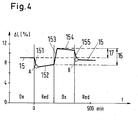
- FIG. 4 shows how the linear extent L of a sample - curve 15 - changes during a redox cycle.
- the Length change .DELTA.L indicated, which has the value at the beginning, which is characterized by the heating to the operating temperature of the fuel cell of 800 ° C and under oxidizing conditions (in the ordinate range "Ox").
- Ox oxidizing conditions
- a constriction with a decrease in length on the curve piece 151 bis to a point A (in the ordinate range "Red”).
- A is the Metal of the sample reduced.
- - curve piece 152 - takes the Length in the reduced state again slightly, probably due to Relaxation processes in which elastic stresses are reduced.
- the resulting from the oxidation extensions are shown in Fig. 4 with the double arrows 16 and 17 shown.
- the double arrow 17 refers to the irreversible extension associated with a redox cycle.
- For a suitable anode substrate would have the irreversible extension 17 be as small as possible. This requirement is an expedient criterion looking for suitable compositions. A search with this Selection criterion has been carried out with a variety of samples.
- the anode substrate which consists of the heterogeneous phase 1b, contains Y stabilized zirconium oxide YSZ in the first subphase and Ni as metal in the second subphase.
- the second phase when the metal is in oxidized form, is wholly or substantially sintered NiO particles.
- the matrix between the large ceramic particles 10 has a heterogeneous grain structure with respect to the NiO particles and small ceramic particles 11.
- the grain size ratio of the heterogeneous grain structure is in the range between 2: 1 and 5: 1;
- the NiO particles have a mean particle size d 50 in the range of 0.5 to 2 microns.
- the quantitative ratio between the first and the second partial phase is in the percent by weight in the range of 50:50 to 25:75, preferably around 40:60.
- the length of the double arrow 17 in the diagram of FIG. 4 has virtually disappeared.
- the micropores and macropores are the Carrier structure 1 evenly distributed.
- the macropores is the Volume fraction 15-35, preferably more than 20% by volume; for the micropores it is preferably less than 10% by volume.
- the mean diameter of the Macropores have values between 3 and 25 ⁇ m, while those of the Micropores have values between 1 and 3 microns.
- the support structure 1 has a layer thickness of 0.3 to 2 mm, preferably 0.6 to 1 mm.
- the fat the electrolyte layer is smaller than 30 ⁇ m, preferably smaller than 15 ⁇ m.
- the metal of second subphase used in oxidized form In the production of a blank for the support structure 1, the metal of second subphase used in oxidized form.
- the material for the Solid electrolyte is, for example, as a slip by means of a Thin-film method applied to said blank. After that will the coated blank sintered.
- To produce the support structure 1 is For example, one of the following sub-methods applicable: film casting, Roll presses, wet presses or isostatic pressing. Of the Thin-layer electrolyte can be applied by other methods: Screen printing, spraying or pouring of slip, slip casting in vacuo ("vacuum slip casting") or reactive spraying.
Abstract
Description
Die Erfindung betrifft eine Hochtemperaturbrennstoffzelle mit einer brennstoffseitigen, eine Anodenschicht umfassenden Trägerstruktur gemäss Oberbegriff von Anspruch 1 sowie eine Hochtemperaturbrennstoffzelle mit einer als Träger ausgebildeten Elektrolytschicht, auf der die Anodenschicht aufgebracht ist. Die Erfindung betrifft auch Verfahren zum Herstellen derartiger Brennstoffzellen.The invention relates to a high-temperature fuel cell with a fuel-side, an anode layer comprehensive carrier structure according to The preamble of claim 1 and a high temperature fuel cell with a formed as a carrier electrolyte layer on which the anode layer is applied. The invention also relates to methods of manufacture such fuel cells.
Aus der nicht vorveröffentlichten EP-A- 1 343 215 (= P.7183) ist eine SOFC-Brennstoffzelle mit einer brennstoffseitigen Trägerstruktur bekannt, die ein Anodensubstrat bildet und als Träger für einen dünnschichtigen Elektrolyten sowie eine Katode dient. Im Kontaktbereich zwischen der Anode, die eine dünne Teilschicht der Trägerstruktur ist, und dem Elektrolyten finden an sogenannten Dreiphasenpunkten (Nickel / Festelektrolyt / Gas) elektrochemische Reaktionen statt, bei denen Nickelatome durch Sauerstoffionen (O2-) des Elektrolyten oxidiert und diese durch einen gasförmigen Brennstoff (H2, CO) wieder reduziert werden, wobei H2O und CO2 gebildet und die bei der Oxidation freigesetzten Elektronen vom Anodensubstrat weiter geleitet werden. Die EP-A- 1 343 215 beschreibt eine Trägerstruktur, die eine "Redoxstabilität" aufweist und die in Bezug auf diese Redoxstabilität, auf Gasdurchlässigkeit sowie Wirtschaftlichkeit für eine Verwendung in Hochtemperatur-Brennstoffzellen ausreichend gut ausgebildet ist. EP-A-1 343 215 (= P.7183), unpublished, discloses an SOFC fuel cell with a fuel-side carrier structure which forms an anode substrate and serves as a carrier for a thin-layered electrolyte and a cathode. In the contact area between the anode, which is a thin sublayer of the support structure, and the electrolyte take place at so-called three-phase points (nickel / solid electrolyte / gas) electrochemical reactions in which nickel atoms by oxygen ions (O 2- ) of the electrolyte oxidized and these by a gaseous Fuel (H 2 , CO) are again reduced, whereby H 2 O and CO 2 are formed and the electrons released during the oxidation are passed on from the anode substrate. EP-A-1 343 215 describes a support structure which has a "redox stability" and which is sufficiently well formed with respect to this redox stability, gas permeability and economy for use in high-temperature fuel cells.
Die Trägerstruktur dieser bekannten Brennstoffzelle ist aus einem Elektrodenmaterial aufgebaut und enthält Makroporen, die mittels Porenbildnern erzeugt sind und die kommunizierende Räume bilden. Das Elektrodenmaterial umfasst skelett- oder netzartige, zusammenhängende Gefüge aus durch Sintern verbundenen Partikeln, sogenannte "Retikularsysteme" (auch als perkolierende Phasen bezeichenbar), die zwei ineinander verschränkte Systeme bilden: ein erstes Retikularsystem aus keramischem Material und ein zweites Retikularsystem, das Metalle oder ein Metall - insbesondere Ni - enthält und das eine elektrisch leitende Verbindung durch die Trägerstruktur herstellt. Das Elektrodenmaterial hat die Eigenschaften, dass bei Durchführen von Redoxzyklen mittels Wechsel zwischen oxidierenden und reduzierenden Bedingungen erstens im keramischen Retikularsystem keine wesentlichen Eigenschaftsänderungen auftreten und zweitens im anderen Retikularsystem sich eine Oxidation bzw. Reduktion des Metalls ergibt. Ausserdem bilden die beiden Retikularsysteme zusammen ein dichtes Gefüge, das im oxidierten Zustand Mikroporen enthält, deren Anteil bezogen auf das Volumen des Elektrodenmaterials kleiner als 5 Vol-% ist oder sein kann.The support structure of this known fuel cell is made of a Electrode material constructed and contains macropores by means of Pore formers are generated and form the communicating spaces. The Electrode material includes skeletal or net-like contiguous Structure of sintered particles, so-called "Reticular systems" (also referred to as percolating phases), the two interlocking systems form: a first reticular system ceramic material and a second reticular system, the metals or a Metal - especially Ni - contains and that is an electrically conductive Making connection through the support structure. The electrode material has the Properties that when performing redox cycles by changing between oxidizing and reducing conditions firstly in ceramic reticular system no significant changes in properties occur secondly and in the other reticular system an oxidation or Reduction of the metal yields. In addition, the two form Retikularsysteme together a dense structure that contains micropores in the oxidized state, their proportion based on the volume of the electrode material is less than 5 Vol% is or can be.
Die beiden Retikularsysteme ergeben sich auf natürliche Weise aus den konstituierenden Partikeln in Form einer statistischen Verteilung der Partikel, wenn diese so präpariert sind, dass die beiden Partikelsorten jeweils ein schmales Grössenspektrum aufweisen, wenn der Anteil für jedes Retikularsystem mindestens rund 30 Vol-% beträgt und wenn die Partikel homogen miteinander vermischt sind. Das durch die Makroporen gebildete System von kommunizierenden Räumen ist ebenfalls ein Retikularsystem. Dieses Hohlraumsystem ergibt die notwendige Gasdurchlässigkeit.The two Retikularsysteme arise naturally from the constituent particles in the form of a statistical distribution of the particles, when these are prepared so that the two particle types each one have a narrow range of sizes, if the proportion for each Reticular system is at least about 30% by volume and if the particles are homogeneously mixed together. The one formed by the macropores System of communicating spaces is also a reticular system. This cavity system provides the necessary gas permeability.
Die beschriebene Trägerstruktur weist zwar die erwünschte Redoxstabilität auf, weist aber in anderer Hinsicht Mängel auf. Während eines Redoxzyklus zieht sich die Struktur beim Übergang vom oxidierten zum reduzierten Zustand zusammen (Konstriktion); die Elektrolytschicht wird entsprechend unter einen kompressiven Druck gesetzt. Der Kompression folgt beim umgekehrten Redox-Übergang eine Expansion. Diese Expansion ist wegen irreversiblen Prozessen in der Trägerstruktur in vielen Anodensubstraten um mehr als 0.1 % grösser als die Kompression. In der Elektrolytschicht, die eine gastrennende Membran darstellt, entstehen wegen der Expansion Risse, wodurch die notwendige Gasdichtheit verloren geht.Although the described support structure has the desired redox stability but has shortcomings in other respects. During a redox cycle the structure contracts during the transition from the oxidized to the reduced one Condition together (constriction); the electrolyte layer becomes corresponding put under a compressive pressure. Compression follows reverse redox transition an expansion. This expansion is due irreversible processes in the support structure in many anode substrates more than 0.1% greater than the compression. In the electrolyte layer, the one represents gas-separating membrane, cracks occur due to the expansion, whereby the necessary gas tightness is lost.
Aufgabe der Erfindung ist es, eine Hochtemperaturbrennstoffzelle mit einer brennstoffseitigen, eine Anodenschicht umfassenden Trägerstruktur zu schaffen, bei der die auf der Trägerstruktur aufgebrachte Elektrolytschicht während eines Redoxzyklus gasdicht bleibt. Diese Aufgabe wird durch die im Anspruch 1 definierte Brennstoffzelle gelöst.The object of the invention is to provide a high-temperature fuel cell with a on the fuel side, an anode layer comprehensive carrier structure in which the electrolyte layer applied to the support structure remains gas-tight during a redox cycle. This task is accomplished by the im Claim 1 defined fuel cell solved.
Die Hochtemperaturbrennstoffzelle umfasst eine brennstoffseitige Trägerstruktur, die eine Anodenschicht umfasst und die als Träger für eine dünne, gasdicht gesinterte Feststoff-Elektrolytschicht dient. Diese Trägerstruktur ist durch eine heterogene Phase gebildet, in der Hohlräume in Form von Makro- sowie Mikroporen enthalten sind. Die heterogene Phase umfasst zwei Teilphasen, die sich verschränkend durchdringen. Die erste Teilphase besteht aus einem keramischen Material und die zweite Teilphase weist Metall auf, für das ein Redoxzyklus mit einem vollständigen Reduzieren und erneuten Oxidieren durchführbar ist. Die erste Teilphase setzt sich aus grossen und kleinen Keramikpartikeln zusammen, aus denen inselartig in der heterogenen Phase angeordnet formstabile "Klettenkorpuskeln" gebildet sind. Die zweite Teilphase stellt bei Vorliegen der reduzierten Form des Metalls eine elektrisch leitende Verbindung durch die Trägerstruktur her. Die grossen und kleinen Keramikpartikel haben mittlere Durchmesser d50 grösser als 5 µm bzw. kleiner als 1 µm. Die Mengenanteile der Keramikpartikel sind derart gewählt, dass die "Klettenkorpuskeln" zu einem "Klettenhaftverbund" assoziiert sind, durch den die Trägerstruktur gegen Formänderungen stabilisiert ist. Durch diese Stabilisierung bleiben die metrischen Eigenschaften der Trägerstruktur an der Grenzfläche zur Elektrolytschicht weitgehend erhalten, so dass Volumenänderungen der zweiten Teilphase während des Redoxzyklus die Gasdichtheit der Elektrolytschicht weitgehend unversehrt lassen.The high-temperature fuel cell comprises a fuel-side carrier structure, which comprises an anode layer and which serves as a carrier for a thin, gastight sintered solid electrolyte layer. This carrier structure is formed by a heterogeneous phase in which cavities in the form of macropores and micropores are contained. The heterogeneous phase comprises two partial phases which interpenetrate. The first subphase consists of a ceramic material and the second subphase comprises metal, for which a redox cycle with complete reduction and reoxidation is feasible. The first subphase is composed of large and small ceramic particles, from which form-like in the heterogeneous phase arranged dimensionally stable "Klettenkorpuskeln" are formed. The second subphase, in the presence of the reduced form of the metal, establishes an electrically conductive connection through the carrier structure. The large and small ceramic particles have average diameter d 50 greater than 5 microns or less than 1 micron. The proportions of the ceramic particles are chosen so that the "Klettenkorpuskeln" are associated to a "Velcro bond", by which the support structure is stabilized against changes in shape. As a result of this stabilization, the metric properties of the carrier structure at the interface with the electrolyte layer are largely retained, so that volume changes of the second partial phase during the redox cycle leave the gas tightness of the electrolyte layer largely intact.
Der abhängige Anspruch 2 bezieht sich auf vorteilhafte Ausführungsformen
der erfindungsgemässen Brennstoffzelle gemäss dem Anspruch 1. The
Für Hochtemperaturbrennstoffzellen, bei denen die Elektrolytschicht als Träger ausgebildet ist und die Anodenschicht auf diesen Träger aufgebracht ist, lässt sich die heterogene Phase, wie sie in Anspruch 1 definiert ist, ebenfalls mit Vorteil gemäss Anspruch 3 verwenden. Die besondere Struktur dieser heterogenen Phase ist ein wirksames Mittel gegen zu grosse Scherkräfte, die aufgrund des Volumenunterschieds von reduziertem und oxidiertem Zustand des Anodenmaterials an der Grenzfläche zwischen der Anoden- und der Elektrolytschicht auftreten und die ein Delaminieren verursachen können.For high-temperature fuel cells in which the electrolyte layer as Carrier is formed and the anode layer applied to this carrier is, can the heterogeneous phase, as defined in claim 1, also with advantage according to claim 3 use. The special structure This heterogeneous phase is an effective remedy against excessive ones Shearing forces due to the volume difference of reduced and Oxidized state of the anode material at the interface between the Anode and the electrolyte layer occur and the one delaminate can cause.
Die abhängigen Ansprüche 4 bis 7 betreffen vorteilhafte Ausführungsformen
der erfindungsgemässen Brennstoffzellen. Verfahren zum Herstellen der
Brennstoffzellen sind Gegenstand der Ansprüche 8 und 9.The dependent claims 4 to 7 relate to advantageous embodiments
the fuel cell according to the invention. Method for producing the
Fuel cells are the subject matter of
Nachfolgend wird die Erfindung anhand der Zeichnungen erläutert. Es zeigen:
- Fig. 1
- eine erfindungsgemässe Brennstoffzelle in schematischer Darstellung,
- Fig. 2
- eine Veranschaulichung eines als "Klettenkorpuskel" bezeichneten Gebildes,
- Fig. 3
- eine Illustration zum Begriff "Klettenhaftverbund" und
- Fig. 4
- ein Diagramm zur Konstriktion und Expansion einer Probe während eines Redoxzyklus.
- Fig. 1
- a fuel cell according to the invention in a schematic representation,
- Fig. 2
- an illustration of a called "Klettenkorpuskel" structure,
- Fig. 3
- an illustration of the term "Klettenhaftverbund" and
- Fig. 4
- a diagram for the constriction and expansion of a sample during a redox cycle.
In einer Hochtemperatur-Brennstoffzelle, wie sie in Fig. 1 schematisch
dargestellt ist, werden Elektrodenreaktionen zur Erzeugung eines elektrischen
Stroms I durchgeführt: nämlich reduzierende Reaktionen in einer
Anodenschicht 1a, die Teil einer Trägerstruktur 1 ist; und oxidierende
Reaktionen auf einer Katode 3, die aus einer elektrochemisch aktiven
Elektrodenschicht 3a und einer zweiten Teilschicht 3b aufgebaut ist. Ein
grösserer Teil 1b der Trägerstruktur 1 ist durch poröse, gasdurchlässige
Retikularsysteme gebildet. In der Anodenschicht 1a entstehen aus
Wasserstoff und Kohlenmonoxid, die den gasförmigen Brennstoff bilden,
Wasser bzw. Kohlendioxid. Auf der Katode 3 reagiert molekularer Sauerstoff
eines zweiten Gasstroms (z. B. Luft) zu ionischem Sauerstoff O2-- unter
Aufnahme von Elektronen e- aus einem metallischen Leiter 40, der eine
Verbindung zu einem Pol 4 herstellt. Die Sauerstoffionen bewegen sich durch
einen Feststoffelektrolyten 2, der eine dünne, gasdicht gesinterte
Elektrolytschicht bildet. Diese trennt die beiden Elektrodenschichten 1a und
3a gasdicht; sie ist bei Temperaturen über 700 °C für die Sauerstoffionen
leitend. Es erfolgt die reduzierende Anodenreaktion mit den Sauerstoffionen
unter Abgabe von Elektronen an einen weiteren metallischen Leiter 50, der
eine Verbindung zu einem Pol 5 herstellt.In a high-temperature fuel cell, as shown schematically in FIG. 1, electrode reactions are carried out to generate an electric current I: namely, reducing reactions in an anode layer 1a forming part of a support structure 1; and oxidizing reactions on a
Zwischen den Polen 4 und 5 ist ein Verbraucher 6 angeordnet, der die
Brennstoffzelle mit einem elektrischen Widerstand belastet. Die Spannung U
zwischen den Polen 4 und 5 wird in der praktischen Anwendung der
Brennstoffzelle durch einen Stapel von in Serie geschalteten Zellen erzeugt.Between the poles 4 and 5, a
Die erfindungsgemässe Hochtemperaturbrennstoffzelle enthält
brennstoffseitig die Trägerstruktur 1, die die Anodenschicht 1a und eine
zweite, durch eine heterogene Phase 1b gebildete Teilschicht umfasst. Durch
die Phase 1b werden Hohlräume in Form von Makro- sowie Mikroporen
gebildet. Die Makroporen ergeben die Gasdurchlässigkeit der Trägerstruktur
1. Die heterogene Phase 1b enthält zwei Teilphasen, die sich verschränkend
durchdringen. Die erste Teilphase besteht aus einem keramischen Material
und die zweite Teilphase weist Metall auf, für das ein Redoxzyklus mit einem
vollständigen Reduzieren und erneuten Oxidieren durchführbar ist. Die zweite
Teilphase stellt bei Vorliegen der reduzierten Form des Metalls eine elektrisch
leitende Verbindung durch die Trägerstruktur 1 her.The high-temperature fuel cell according to the invention contains
Fuel side, the support structure 1, the anode layer 1a and a
second, formed by a
Die erste Teilphase setzt sich aus grossen und kleinen Keramikpartikeln 10
bzw. 11 zusammen, aus denen inselartig in der heterogenen Phase 1b
angeordnet formstabile "Klettenkorpuskeln" 12 und 13 gebildet sind: siehe
Fig. 2. Die grossen Keramikpartikel 10 haben mittlere Durchmesser d50
grösser als 5 oder 10 µm; vorzugsweise ist dieser Durchmesser rund 20 µm.
Für die kleinen Keramikpartikel 11 ist der mittlere Durchmesser d50 kleiner als
1 µm. The first subphase is composed of large and small
Die zweite Teilphase bildet zusammen mit den kleinen Keramikpartikeln 11
der ersten Teilphase eine angenähert homogene Matrix. In dieser Matrix sind
die grossen Keramikpartikel 10 gleichmässig verteilt eingebettet. Die
Teilchendichte der kleinen Keramikpartikel 11 ist derart gewählt, dass Cluster
von jeweils einer Vielzahl an Partikeln 11 auftreten. Beim Sintern der
Trägerstruktur verbinden sich die Partikel 11 in den Clustern zu formstabilen
Gebilden 13 oder 13'. Beim Sintern fügen sich überdies die einen dieser
Gebilde, die Gebilde 13', mit den grossen Keramikpartikeln 10 zu "grossen
Klettenkorpuskeln" 12 zusammen. Ein solches grosses Klettenkorpuskel 12
besteht aus einem Rumpf, der aus einem grossen Keramikpartikel 10 besteht,
und einem Hof 100, in dem sich die angefügten Gebilde 13' befinden. Die
mittlere Ausdehnung des Hofes 100 ist durch die strichpunktiert gezeichnete
Kugel 101 in Fig. 2 angegeben. Je grösser die Teilchendichte der kleinen
Keramikpartikel 11 gewählt ist, desto grösser ist der Durchmesser der Kugel
101. Dieser Durchmesser hängt auch von der Grösse der kleinen
Keramikpartikeln 11 ab. Er hängt also von der Teilchendichte der kleinen
Keramikpartikeln 11 sowie von den Durchmessern der grossen und kleinen
Keramikpartikeln 10 bzw. 11 ab.The second subphase forms together with the small
Ausser dem Klettenkorpuskel 12 sind in Fig. 2 auch kleine Kugeln 110
strichpunktiert eingezeichnet. Diese Kugeln sind den Gebilden 13 zugeordnet,
die mit den grossen Keramikpartikeln 10 nicht verbunden sind. Die
Durchmesser der Kugeln 110 wachsen ebenfalls mit zunehmender
Teilchendichte der kleinen Keramikpartikel 11. Übersteigt diese
Teilchendichte eine kritische Grösse, so verbinden sich die kleinen
Keramikpartikel 11 zu einer perkolierenden Phase, in der sich die Kugeln 110
zu einem einzigen Verbund vereinigt haben. Die Teilchendichte der kleinen
Keramikpartikel 11 sowie deren Grösse werden so gewählt, dass die Kugeln
110 markant kleinere Durchmesser als die Kugeln 101 aufweisen. Die
zugeordneten Gebilde 13, die sich innerhalb der oben genannten Matrix
befinden, werden nachfolgend als "kleine Klettenkorpuskeln" 13 bezeichnet.In addition to the
Die Mengenanteile der Keramikpartikel werden derart gewählt, dass die
Klettenkorpuskeln 12, 13 sich zu einem "Klettenhaftverbund" assoziieren,
durch den die Trägerstruktur 1 gegen Formänderungen stabilisiert ist: siehe
Fig. 3. Formänderungen können sich beim Reduzieren der zweiten Teilphase
(zweites Retikularsystem) ergeben. Bei diesem Prozess, der mit einer
Konstriktion verbunden ist, werden die Partikel, die anfänglich aus dem
Metalloxid bestehen, beweglich. Sie ordnen sich neu an, wobei die
makroskopische Form der Trägerstruktur 1 sich verändern kann. Eine solche
Formänderung wird durch die Stabilisierung stark eingeschränkt. Diese ergibt
sich durch ein Verhaken der Gebilde 13' in den Höfen 100, wenn die grossen
Klettenkorpuskeln 12 so dicht angeordnet sind, dass Höfe 100 benachbarter
Klettenkorpuskeln 12 sich überlappen. Die kleinen Klettenkorpuskeln 13
tragen ebenfalls durch ein Verhaken zur Haftung zwischen den grossen
Klettenkorpuskeln 12 bei. Beim Reduzieren der zweiten Teilphase kann sich
die Trägerstruktur dank des Klettenhaftverbunds nur sehr beschränkt
zusammen ziehen. Die Klettenkorpuskel 12 und 13, die sich aufgrund von
Verhakungen assoziieren, bilden einen Verbund, den Klettenhaftverbund, der
bezüglich kleinen Dehnungen sehr flexibel ist und nur geringe Spannungen
entstehen lässt. Die Elektrolytschicht, die relativ starr ist, wird daher durch die
Trägerstruktur 1, in der die zweite Teilphase ein fluidartiges Verhalten
während des Konstriktionsprozesses zeigt, nur mit schwachen Zugkräften
beansprucht.The proportions of the ceramic particles are chosen such that the
Auch beim Oxidieren wird die Trägerstruktur 1 durch den Klettenhaftverbund
entsprechend stabilisiert. Durch diese Stabilisierung bleiben die metrischen
Eigenschaften der Trägerstruktur 1 an der Grenzfläche zur Elektrolytschicht 2
weitgehend erhalten. Volumenänderungen der zweiten Teilphase während
des Redoxzyklus lassen daher die Gasdichtheit der Elektrolytschicht
unversehrt, so dass der Wirkungsgrad der Brennstoffzelle erhalten bleibt;
oder die Gasdichtheit wird nur so weit beeinträchtigt, dass beim Wirkungsgrad
eine tolerierbare Einbusse resultiert.Also during the oxidation, the support structure 1 by the Velcro bond
stabilized accordingly. By this stabilization remain the metric
Properties of the carrier structure 1 at the interface to the
Zwischen der Anoden- und der Elektolytschicht entstehen auch Scherkräfte, wenn der Oxidationszustand des Anodenmaterials sich ändert. Aufgrund des Klettenhaftverbunds sind diese Scherkräfte relativ schwach. Im Fall, dass die Anodenschicht auf einer als Träger verwendeten Elektolytschicht aufgebracht ist, reichen solche Scherkräfte in der Regel nicht aus, eine Delaminierung der Anodenschicht zu verursachen. Shearing forces also arise between the anode and electrolyte layers. when the oxidation state of the anode material changes. Due to the Velcro bonding these shear forces are relatively weak. In the event that the Anode layer applied to a Elektrolytschicht used as a carrier is such shearing forces usually not sufficient, a delamination of Anode layer to cause.
In Fig. 4 ist gezeigt, wie die lineare Ausdehnung L einer Probe - Kurve 15 -
sich während eines Redoxzyklus ändert. Auf der Abszisse ist die
Längenänderung ΔL angegeben, die am Anfang den Wert hat, der sich durch
die Erwärmung auf die Betriebstemperatur der Brennstoffzelle von 800 °C und
bei oxidierenden Bedingungen ergibt (im Ordinatenbereich "Ox"). Bei
reduzierenden Bedingungen aufgrund einer Wasserstoffatmosphäre ergibt
sich eine Konstriktion mit einer Längenabnahme auf dem Kurvenstück 151 bis
zu einem Punkt A (im Ordinatenbereich "Red"). Bei diesem Punkt A ist das
Metall der Probe reduziert. Anschliessend - Kurvenstück 152 - nimmt die
Länge im reduzierten Zustand wieder etwas zu, wahrscheinlich aufgrund von
Relaxationsvorgängen, bei denen elastische Spannungen abgebaut werden.
Wird der Wasserstoff durch Luft ersetzt, so nimmt durch die Oxidation die
lineare Ausdehnung L wieder zu (Kurvenstück 153) und zwar mehr, als zuvor
bei der Reduktion die Länge abgenommen hat. Im oxidierten Zustand ergibt
sich wieder eine kleine Längenänderung, möglicherweise auch aufgrund von
Relaxationsphänomenen: Kurvenstück 154. Bei erneutem Reduzieren
verkürzt sich die lineare Ausdehnung L wieder: Kurvenstück 155, Punkt B. Mit
dem Punkt B ist der beim Punkt A begonnene Redoxzyklus abgeschlossen.
Die beiden Punkte A und B müssten auf der gleichen Höhe liegen, falls
während des Redoxzyklus nur reversible Prozesse auftreten würden. Wie in
Fig. 5 ersichtlich ist, liegt eine irreversible Verlängerung vor.FIG. 4 shows how the linear extent L of a sample - curve 15 -
changes during a redox cycle. On the abscissa is the
Length change .DELTA.L indicated, which has the value at the beginning, which is characterized by
the heating to the operating temperature of the fuel cell of 800 ° C and
under oxidizing conditions (in the ordinate range "Ox"). at
resulting in reducing conditions due to a hydrogen atmosphere
a constriction with a decrease in length on the
Die aufgrund der Oxidation entstandenen Verlängerungen sind in Fig. 4 mit
den Doppelpfeilen 16 und 17 dargestellt. Der Doppelpfeil 17 bezieht sich auf
die irreversible Verlängerung, die mit einem Redoxzyklus verbunden ist. Für
ein geeignetes Anodensubstrat müsste die irreversible Verlängerung 17
möglichst klein sein. Dieses Erfordernis ist ein zweckmässiges Kriterium bei
der Suche nach geeigneten Zusammensetzungen. Eine Suche mit diesem
Auswahlkriterium ist mit einer Vielzahl von Proben durchgeführt worden. The resulting from the oxidation extensions are shown in Fig. 4 with
the
Das Anodensubstrat, das aus der heterogenen Phase 1 b besteht, enthält in
der ersten Teilphase mit Y stabilisiertes Zirkoniumoxid YSZ und in der zweiten
Teilphase Ni als Metall. Die zweite Teilphase besteht, wenn das Metall in
oxidierter Form vorliegt, ganz oder weitgehend aus durch Sintern
zusammengefügten NiO-Partikeln. Die Matrix zwischen den grossen
Keramikpartikeln 10 hat bezüglich den NiO-Partikeln und kleinen
Keramikpartikeln 11 eine heterogene Kornstruktur. Für untersuchte Proben,
deren Zusammensetzungen sich als vorteilhaft erwiesen haben, ist das
Korngrössenverhältnis der heterogenen Kornstruktur im Bereich zwischen 2:1
und 5:1; die NiO-Partikel haben dabei eine mittlere Korngrösse d50 im Bereich
von 0.5 bis 2 µm. Das Mengenverhältnis zwischen der ersten und der zweiten
Teilphase liegt - in Gewichtsprozenten - im Bereich von 50:50 bis 25:75,
vorzugsweise bei rund 40:60.The anode substrate, which consists of the
Bei einer besonders vorteilhaften Probe ist die Länge des Doppelpfeils 17 im Diagramm der Fig. 4 praktisch verschwunden. Diese Probe ist durch folgende Parameter charakterisiert: 60 Gew-% und d50 = 0.74 µm für NiO; 40 Gew-% und d50 = 0.2 bzw. 20 µm für YSZ mit zwei Teilen grobem YSZ und einem Teil feinem YSZ.In a particularly advantageous sample, the length of the double arrow 17 in the diagram of FIG. 4 has virtually disappeared. This sample is characterized by the following parameters: 60% by weight and d 50 = 0.74 μm for NiO; 40% by weight and d 50 = 0.2 or 20 μm for YSZ with two parts of coarse YSZ and one part of fine YSZ.
Ausserhalb der Anodenschicht 1a sind die Mikro- und Makroporen der Trägerstruktur 1 gleichmässig verteilt. Für die Makroporen beträgt der Volumenanteil 15 - 35, vorzugsweise mehr als 20 Vol-%; für die Mikroporen beträgt er vorzugsweise weniger als 10 Vol-%. Die mittleren Durchmesser der Makroporen haben Werte zwischen 3 und 25 µm, während jene der Mikroporen Werte zwischen 1 und 3 µm aufweisen. Die Trägerstruktur 1 hat eine Schichtdicke von 0.3 bis 2 mm, vorzugsweise 0.6 bis 1 mm. Die Dicke der Elektrolytschicht ist kleiner als 30 µm, vorzugsweise kleiner als 15 µm.Outside the anode layer 1a, the micropores and macropores are the Carrier structure 1 evenly distributed. For the macropores is the Volume fraction 15-35, preferably more than 20% by volume; for the micropores it is preferably less than 10% by volume. The mean diameter of the Macropores have values between 3 and 25 μm, while those of the Micropores have values between 1 and 3 microns. The support structure 1 has a layer thickness of 0.3 to 2 mm, preferably 0.6 to 1 mm. The fat the electrolyte layer is smaller than 30 μm, preferably smaller than 15 μm.
Bei einem Verfahren zum Herstellen der erfindungsgemässen Brennstoffzelle wird bei der Erzeugung eines Rohlings für die Trägerstruktur 1 das Metall der zweiten Teilphase in oxidierter Form verwendet. Das Material für den Festelektrolyten wird beispielsweise als Schlicker mittels einem Dünnschichtverfahren auf den genannten Rohling aufgebracht. Danach wird der beschichtete Rohling gesintert. Zur Erzeugung der Trägerstruktur 1 ist beispielsweise eines der folgenden Teilverfahren anwendbar: Foliengiessen, Rollpressen, Nasspressen oder isostatisches Pressen. Der Dünnschichtelektrolyt kann mittels anderer Verfahren aufgebracht werden: Siebdruck, Aufsprühen oder Giessen von Schlicker, Schlickerguss im Vakuum ("vacuum slip casting") oder reaktives Aufspritzen.In a method for producing the fuel cell according to the invention In the production of a blank for the support structure 1, the metal of second subphase used in oxidized form. The material for the Solid electrolyte is, for example, as a slip by means of a Thin-film method applied to said blank. After that will the coated blank sintered. To produce the support structure 1 is For example, one of the following sub-methods applicable: film casting, Roll presses, wet presses or isostatic pressing. Of the Thin-layer electrolyte can be applied by other methods: Screen printing, spraying or pouring of slip, slip casting in vacuo ("vacuum slip casting") or reactive spraying.
Claims (9)
dadurch gekennzeichnet, dass die grossen und kleinen Keramikpartikel mittlere Durchmesser d50 grösser als 5 µm bzw. kleiner als 1 µm haben, die Mengenanteile der Keramikpartikel derart gewählt sind, dass die "Klettenkorpuskeln" zu einem "Klettenhaftverbund" assoziiert sind, durch den die Trägerstruktur gegen Formänderungen stabilisiert ist, wobei durch diese Stabilisierung die metrischen Eigenschaften der Trägerstruktur an der Grenzfläche zur Elektrolytschicht weitgehend erhalten bleiben, so dass Volumenänderungen der zweiten Teilphase während des Redoxzyklus die Gasdichtheit der Elektrolytschicht weitgehend unversehrt lassen.High-temperature fuel cell having a fuel-side, an anode layer (1a) comprehensive support structure (1) as a support for a thin gas-sintered solid electrolyte layer (2), which support structure a heterogeneous phase (1b) and formed by this phase voids in the form of macro- and Micropores, wherein the heterogeneous phase contains two sub-phases, which interpenetrate penetrate, the first sub-phase consists of a ceramic material and the second sub-phase comprises metal, for which a redox cycle with a complete reduction and re-oxidation is feasible, the first part of phase large and small ceramic particles (10, 11) composed of which are arranged island-like in the heterogeneous phase dimensionally stable "Klettenkorpuskeln" (12, 13) are formed, and the second subphase produces an electrically conductive connection through the support structure in the presence of the reduced form of the metal .
characterized in that the large and small ceramic particles have average diameter d 50 greater than 5 microns or less than 1 micron, the proportions of the ceramic particles are chosen such that the "Klettenkorpuskeln" are associated to a "Velcro bond" through which the support structure is stabilized against changes in shape, the metric properties of the carrier structure at the interface with the electrolyte layer being largely retained by this stabilization, so that volume changes of the second partial phase during the redox cycle leave the gas tightness of the electrolyte layer largely intact.
dadurch gekennzeichnet, dass die grossen und kleinen Keramikpartikel mittlere Durchmesser d50 grösser als 5 µm bzw. kleiner als 1 µm haben, die Mengenanteile der Keramikpartikel derart gewählt sind, dass die "Klettenkorpuskeln" zu einem "Klettenhaftverbund" assoziiert sind, durch den die Anodenschicht gegen Formänderungen stabilisiert ist, wobei durch diese Stabilisierung die metrischen Eigenschaften der Anodenschicht an der Grenzfläche zur Elektrolytschicht weitgehend erhalten bleiben und so nur schwache Scherkräfte entstehen, die kein Delaminieren der Anodenschicht verursachen.High-temperature fuel cell having a solid electrolyte layer, which is formed as a support for electrode layers and gas-tightly separates an anode from a cathode layer, wherein the anode layer applied to the fuel side forms a heterogeneous phase with two sub-phases that interpenetrately penetrate, the first sub-phase of a ceramic material and the second subphase comprises metal, for which a redox cycle with a complete reduction and reoxidation is feasible, the first subphase is composed of large and small ceramic particles (10, 11), from which island-like in the heterogeneous phase arranged dimensionally stable " Klettenkorpuskeln "(12, 13) are formed, and the second sub-phase in the presence of the reduced form of the metal makes an electrically conductive connection through the support structure,
characterized in that the large and small ceramic particles have average diameter d 50 greater than 5 microns or less than 1 micron, the proportions of the ceramic particles are chosen such that the "Klettenkorpuskeln" are associated to a "Velcro bond" through which the anode layer is stabilized against changes in shape, this stabilization largely preserving the metric properties of the anode layer at the interface with the electrolyte layer and thus producing only weak shearing forces which do not cause delamination of the anode layer.
Priority Applications (1)
| Application Number | Priority Date | Filing Date | Title |
|---|---|---|---|
| EP04405500A EP1513214A1 (en) | 2003-09-05 | 2004-08-06 | High temperature fuel cell with stabilized cermet structure |
Applications Claiming Priority (3)
| Application Number | Priority Date | Filing Date | Title |
|---|---|---|---|
| EP03405649 | 2003-09-05 | ||
| EP03405649 | 2003-09-05 | ||
| EP04405500A EP1513214A1 (en) | 2003-09-05 | 2004-08-06 | High temperature fuel cell with stabilized cermet structure |
Publications (1)
| Publication Number | Publication Date |
|---|---|
| EP1513214A1 true EP1513214A1 (en) | 2005-03-09 |
Family
ID=34137613
Family Applications (1)
| Application Number | Title | Priority Date | Filing Date |
|---|---|---|---|
| EP04405500A Withdrawn EP1513214A1 (en) | 2003-09-05 | 2004-08-06 | High temperature fuel cell with stabilized cermet structure |
Country Status (1)
| Country | Link |
|---|---|
| EP (1) | EP1513214A1 (en) |
Cited By (10)
| Publication number | Priority date | Publication date | Assignee | Title |
|---|---|---|---|---|
| EP1596458A1 (en) * | 2004-03-29 | 2005-11-16 | Sulzer Hexis AG | Anode material for a high-temperature fuel cell |
| WO2013045209A1 (en) * | 2011-09-27 | 2013-04-04 | Siemens Aktiengesellschaft | Storage element and method for the production thereof |
| WO2013045225A1 (en) * | 2011-09-27 | 2013-04-04 | Siemens Aktiengesellschaft | Storage element for a solid electrolyte battery |
| WO2013045217A1 (en) * | 2011-09-27 | 2013-04-04 | Siemens Aktiengesellschaft | Storage element |
| WO2013045208A1 (en) * | 2011-09-27 | 2013-04-04 | Siemens Aktiengesellschaft | Storage element and method for the production thereof |
| WO2013045211A1 (en) * | 2011-09-27 | 2013-04-04 | Siemens Aktiengesellschaft | Storage element |
| WO2013045223A1 (en) * | 2011-09-27 | 2013-04-04 | Siemens Aktiengesellschaft | Storage element for a solid electrolyte battery and method for the production thereof |
| WO2013045218A1 (en) * | 2011-09-27 | 2013-04-04 | Siemens Aktiengesellschaft | Storage element |
| EP2712011A1 (en) * | 2011-05-18 | 2014-03-26 | Toto Ltd. | Solid oxide type fuel battery cell and method for fabricating solid oxide type fuel battery cell |
| WO2014111273A1 (en) * | 2013-01-16 | 2014-07-24 | Siemens Aktiengesellschaft | Rechargeable electric energy accumulator |
Citations (6)
| Publication number | Priority date | Publication date | Assignee | Title |
|---|---|---|---|---|
| EP0788175A1 (en) * | 1996-02-02 | 1997-08-06 | Sulzer Innotec Ag | High temperature fuel cell with an electrolyte thin film |
| US5908713A (en) * | 1997-09-22 | 1999-06-01 | Siemens Westinghouse Power Corporation | Sintered electrode for solid oxide fuel cells |
| EP1026123A2 (en) * | 1999-02-02 | 2000-08-09 | Praxair Technology, Inc. | Multi-phase solid ion and electron conducting membrane with low volume percentage electron conducting phase and methods for fabricating same |
| WO2001057945A1 (en) * | 2000-02-04 | 2001-08-09 | Stichting Energieonderzoek Centrum Nederland | Method of fabricating an assembly comprising an anode-supported electrolyte, and ceramic cell comprising such an assembly |
| EP1246288A1 (en) * | 2001-03-28 | 2002-10-02 | Sulzer Hexis AG | Porous gas-permeable substructure layer of a thin gas impervious layer for use as functional component in high temperature fuel cells |
| US20030165726A1 (en) * | 2002-03-04 | 2003-09-04 | Sulzer Hexis Ag | Structured body for an anode used in fuel cells |
-
2004
- 2004-08-06 EP EP04405500A patent/EP1513214A1/en not_active Withdrawn
Patent Citations (6)
| Publication number | Priority date | Publication date | Assignee | Title |
|---|---|---|---|---|
| EP0788175A1 (en) * | 1996-02-02 | 1997-08-06 | Sulzer Innotec Ag | High temperature fuel cell with an electrolyte thin film |
| US5908713A (en) * | 1997-09-22 | 1999-06-01 | Siemens Westinghouse Power Corporation | Sintered electrode for solid oxide fuel cells |
| EP1026123A2 (en) * | 1999-02-02 | 2000-08-09 | Praxair Technology, Inc. | Multi-phase solid ion and electron conducting membrane with low volume percentage electron conducting phase and methods for fabricating same |
| WO2001057945A1 (en) * | 2000-02-04 | 2001-08-09 | Stichting Energieonderzoek Centrum Nederland | Method of fabricating an assembly comprising an anode-supported electrolyte, and ceramic cell comprising such an assembly |
| EP1246288A1 (en) * | 2001-03-28 | 2002-10-02 | Sulzer Hexis AG | Porous gas-permeable substructure layer of a thin gas impervious layer for use as functional component in high temperature fuel cells |
| US20030165726A1 (en) * | 2002-03-04 | 2003-09-04 | Sulzer Hexis Ag | Structured body for an anode used in fuel cells |
Cited By (16)
| Publication number | Priority date | Publication date | Assignee | Title |
|---|---|---|---|---|
| EP1596458A1 (en) * | 2004-03-29 | 2005-11-16 | Sulzer Hexis AG | Anode material for a high-temperature fuel cell |
| EP2712011A4 (en) * | 2011-05-18 | 2014-12-03 | Toto Ltd | Solid oxide type fuel battery cell and method for fabricating solid oxide type fuel battery cell |
| EP2712011A1 (en) * | 2011-05-18 | 2014-03-26 | Toto Ltd. | Solid oxide type fuel battery cell and method for fabricating solid oxide type fuel battery cell |
| WO2013045208A1 (en) * | 2011-09-27 | 2013-04-04 | Siemens Aktiengesellschaft | Storage element and method for the production thereof |
| WO2013045217A1 (en) * | 2011-09-27 | 2013-04-04 | Siemens Aktiengesellschaft | Storage element |
| WO2013045211A1 (en) * | 2011-09-27 | 2013-04-04 | Siemens Aktiengesellschaft | Storage element |
| WO2013045223A1 (en) * | 2011-09-27 | 2013-04-04 | Siemens Aktiengesellschaft | Storage element for a solid electrolyte battery and method for the production thereof |
| WO2013045218A1 (en) * | 2011-09-27 | 2013-04-04 | Siemens Aktiengesellschaft | Storage element |
| WO2013045225A1 (en) * | 2011-09-27 | 2013-04-04 | Siemens Aktiengesellschaft | Storage element for a solid electrolyte battery |
| CN103828098A (en) * | 2011-09-27 | 2014-05-28 | 西门子公司 | Storage element and method for the production thereof |
| WO2013045209A1 (en) * | 2011-09-27 | 2013-04-04 | Siemens Aktiengesellschaft | Storage element and method for the production thereof |
| US9570782B2 (en) | 2011-09-27 | 2017-02-14 | Siemens Aktiengesellschaft | Storage element and method for the production thereof |
| US9660256B2 (en) | 2011-09-27 | 2017-05-23 | Siemens Aktiengesellschaft | Storage element for a solid electrolyte battery |
| US9660257B2 (en) | 2011-09-27 | 2017-05-23 | Siemens Aktiengesellschaft | Storage element |
| US9825282B2 (en) | 2011-09-27 | 2017-11-21 | Siemens Aktiengesellschaft | Storage element and process for the production thereof |
| WO2014111273A1 (en) * | 2013-01-16 | 2014-07-24 | Siemens Aktiengesellschaft | Rechargeable electric energy accumulator |
Similar Documents
| Publication | Publication Date | Title |
|---|---|---|
| EP0696386B1 (en) | High-temperature fuel cell with improved solid electrolyte/electrode contact surface, and method of producing the contact surface | |
| EP2036152B1 (en) | Ceramic material combination for an anode of a high-temperature fuel cell | |
| EP1343215B1 (en) | Structured body used as anode in fuel cell | |
| DE60118884T2 (en) | METHOD FOR PRODUCING AN ANODIS-CARRYING ELECTROLYTE-CONTAINING ARRANGEMENT AND CERAMIC CELL CONTAINING SUCH AN ARRANGEMENT | |
| EP1738428B1 (en) | Electrically conductive steel-ceramic connection and method for the production thereof | |
| DE19963882A1 (en) | Electrode for high temperature fuel cell and method of manufacturing the same | |
| EP2050155B1 (en) | Electrode for a molten carbonate fuel cell and process for its production | |
| DE10031102C2 (en) | Process for producing a composite body, in particular an electrode with temperature-resistant conductivity | |
| EP1513214A1 (en) | High temperature fuel cell with stabilized cermet structure | |
| EP2245692B1 (en) | Electrolyte for cost-effective, electrolyte-supported high-temperature fuel cell having high performance and high mechanical strength | |
| DE60123839T2 (en) | STACKED MICROSTRUCTURES OF LEADING, CERAMIC OXIDION MEMBRANES; USE FOR THE SEPARATION OF OXYGEN FROM AIR | |
| WO2009076977A1 (en) | Bipolar plate and method for producing a protective layer on a bipolar plate | |
| WO2012062263A1 (en) | Method for producing solid oxide fuel cells having a cathode-electrolyte-anode unit borne by a metal substrate, and use of said solid oxide fuel cells | |
| EP2669984B1 (en) | Layered anode system for electrochemical applications and process of manufacturing the same | |
| EP2332205A1 (en) | High temperature fuel cell and associated fuel cell assembly | |
| EP1596458A1 (en) | Anode material for a high-temperature fuel cell | |
| WO2006136257A1 (en) | High temperature fuel cell having a metallic supporting structure for the solid oxide functional layers | |
| DE60115490T2 (en) | ANODE COMPOSITION FOR AN ELECTROCHEMICAL CELL | |
| DE10212966B4 (en) | High-temperature fuel cell and method for its production | |
| WO2008119321A1 (en) | Layer system for an electrolyte of a high-temperature fuel cell, and method for producing same | |
| WO2018096022A1 (en) | Anode for an electrochemical cell and method for producing an electrochemical cell comprising such an anode | |
| DE19649376C1 (en) | Electrode reinforced by ceramic particles | |
| EP3697944B1 (en) | Fuel gas electrode and method for producing a fuel gas electrode | |
| EP3035429B1 (en) | Composite electrolyte for a solid oxide fuel cell, exhaust gas probe or high-temperature gas-sensor | |
| DE10163013A1 (en) | Anode used in solid electrolyte fuel cell has a base material made from a cermet with palladium or palladium alloys as the catalytic component |
Legal Events
| Date | Code | Title | Description |
|---|---|---|---|
| PUAI | Public reference made under article 153(3) epc to a published international application that has entered the european phase |
Free format text: ORIGINAL CODE: 0009012 |
|
| AK | Designated contracting states |
Kind code of ref document: A1 Designated state(s): AT BE BG CH CY CZ DE DK EE ES FI FR GB GR HU IE IT LI LU MC NL PL PT RO SE SI SK TR |
|
| AX | Request for extension of the european patent |
Extension state: AL HR LT LV MK |
|
| 17P | Request for examination filed |
Effective date: 20050811 |
|
| AKX | Designation fees paid |
Designated state(s): AT BE BG CH CY CZ DE DK EE ES FI FR GB GR HU IE IT LI LU MC NL PL PT RO SE SI SK TR |
|
| STAA | Information on the status of an ep patent application or granted ep patent |
Free format text: STATUS: THE APPLICATION IS DEEMED TO BE WITHDRAWN |
|
| 18D | Application deemed to be withdrawn |
Effective date: 20060523 |