EP1513250A2 - Method in salient-pole permanent magnet synchronous machine - Google Patents
Method in salient-pole permanent magnet synchronous machine Download PDFInfo
- Publication number
- EP1513250A2 EP1513250A2 EP04103992A EP04103992A EP1513250A2 EP 1513250 A2 EP1513250 A2 EP 1513250A2 EP 04103992 A EP04103992 A EP 04103992A EP 04103992 A EP04103992 A EP 04103992A EP 1513250 A2 EP1513250 A2 EP 1513250A2
- Authority
- EP
- European Patent Office
- Prior art keywords
- rotor
- angular speed
- permanent magnet
- voltage
- estimate
- Prior art date
- Legal status (The legal status is an assumption and is not a legal conclusion. Google has not performed a legal analysis and makes no representation as to the accuracy of the status listed.)
- Granted
Links
- 238000000034 method Methods 0.000 title claims abstract description 38
- 230000001360 synchronised effect Effects 0.000 title claims abstract description 28
- 238000002347 injection Methods 0.000 claims abstract description 36
- 239000007924 injection Substances 0.000 claims abstract description 36
- 230000015572 biosynthetic process Effects 0.000 claims description 3
- 230000004907 flux Effects 0.000 description 23
- 238000010586 diagram Methods 0.000 description 8
- 230000014509 gene expression Effects 0.000 description 5
- 238000013519 translation Methods 0.000 description 4
- 230000000694 effects Effects 0.000 description 3
- 238000012986 modification Methods 0.000 description 3
- 230000004048 modification Effects 0.000 description 3
- 238000012546 transfer Methods 0.000 description 3
- 230000005284 excitation Effects 0.000 description 2
- 238000001914 filtration Methods 0.000 description 2
- 230000010354 integration Effects 0.000 description 2
- 238000005259 measurement Methods 0.000 description 2
- 230000003321 amplification Effects 0.000 description 1
- 238000013459 approach Methods 0.000 description 1
- 238000004364 calculation method Methods 0.000 description 1
- 230000001419 dependent effect Effects 0.000 description 1
- 230000006698 induction Effects 0.000 description 1
- 238000003199 nucleic acid amplification method Methods 0.000 description 1
- 239000007787 solid Substances 0.000 description 1
- 230000003068 static effect Effects 0.000 description 1
Images


Classifications
-
- H—ELECTRICITY
- H02—GENERATION; CONVERSION OR DISTRIBUTION OF ELECTRIC POWER
- H02P—CONTROL OR REGULATION OF ELECTRIC MOTORS, ELECTRIC GENERATORS OR DYNAMO-ELECTRIC CONVERTERS; CONTROLLING TRANSFORMERS, REACTORS OR CHOKE COILS
- H02P21/00—Arrangements or methods for the control of electric machines by vector control, e.g. by control of field orientation
- H02P21/24—Vector control not involving the use of rotor position or rotor speed sensors
- H02P21/28—Stator flux based control
-
- H—ELECTRICITY
- H02—GENERATION; CONVERSION OR DISTRIBUTION OF ELECTRIC POWER
- H02P—CONTROL OR REGULATION OF ELECTRIC MOTORS, ELECTRIC GENERATORS OR DYNAMO-ELECTRIC CONVERTERS; CONTROLLING TRANSFORMERS, REACTORS OR CHOKE COILS
- H02P21/00—Arrangements or methods for the control of electric machines by vector control, e.g. by control of field orientation
- H02P21/14—Estimation or adaptation of machine parameters, e.g. flux, current or voltage
- H02P21/18—Estimation of position or speed
-
- H—ELECTRICITY
- H02—GENERATION; CONVERSION OR DISTRIBUTION OF ELECTRIC POWER
- H02P—CONTROL OR REGULATION OF ELECTRIC MOTORS, ELECTRIC GENERATORS OR DYNAMO-ELECTRIC CONVERTERS; CONTROLLING TRANSFORMERS, REACTORS OR CHOKE COILS
- H02P2203/00—Indexing scheme relating to controlling arrangements characterised by the means for detecting the position of the rotor
- H02P2203/05—Determination of the rotor position by using two different methods and/or motor models
-
- H—ELECTRICITY
- H02—GENERATION; CONVERSION OR DISTRIBUTION OF ELECTRIC POWER
- H02P—CONTROL OR REGULATION OF ELECTRIC MOTORS, ELECTRIC GENERATORS OR DYNAMO-ELECTRIC CONVERTERS; CONTROLLING TRANSFORMERS, REACTORS OR CHOKE COILS
- H02P2203/00—Indexing scheme relating to controlling arrangements characterised by the means for detecting the position of the rotor
- H02P2203/11—Determination or estimation of the rotor position or other motor parameters based on the analysis of high frequency signals
-
- H—ELECTRICITY
- H02—GENERATION; CONVERSION OR DISTRIBUTION OF ELECTRIC POWER
- H02P—CONTROL OR REGULATION OF ELECTRIC MOTORS, ELECTRIC GENERATORS OR DYNAMO-ELECTRIC CONVERTERS; CONTROLLING TRANSFORMERS, REACTORS OR CHOKE COILS
- H02P2207/00—Indexing scheme relating to controlling arrangements characterised by the type of motor
- H02P2207/05—Synchronous machines, e.g. with permanent magnets or DC excitation
Definitions
- the present invention relates to a method in connection with a salient-pole permanent magnet synchronous machine in accordance with the preamble of claim 1.
- a plurality of motor control systems require accurate information on a position angle and angular speed of a rotor.
- the position angle and the angular speed of the rotor are determined using a mechanical sensor coupled on a motor shaft.
- This sensor produces information, for instance, on the rotor position and from a change in the position it is further possible to calculate the angular speed of the rotor.
- the sensor coupled to the shaft is a mechanical component liable to faults, which increases the price of a motor drive considerably.
- the motor drive control is based on information obtained from the sensor, sensor breakage inevitably causes downtime in said motor drive.
- the voltage models produce an accurate estimate on the angular speed of the rotor at its higher values.
- the voltage models have a drawback that at near-zero speed the estimate obtained by the voltage model becomes inaccurate, due to possibly erroneous parameters and measurement inaccuracies together with a low back EMF produced by the machine.
- One manner to estimate a rotor position angle in a motion sensorless synchronous machine is based on utilizing signal injection methods.
- signal injection an extra signal deviating from the fundamental frequency is injected to the motor either in voltage or in current form. This signal provides in the machine an injection frequency response, from which is obtained by demodulation a position tracking signal that can be used for determining the position of the rotor.
- Signal injection methods enable operation at low speeds down to zero speed, but the obtained dynamic behaviour is poor, however.
- the object of the invention is to provide a method, which avoids the above drawbacks and enables the determination of the angular speed and the position angle of a permanent magnet synchronous machine in a reliable manner on a wide operating range. This is achieved with a method that is characterized by what is stated in the characterizing part of the independent claim.
- the preferred embodiments of the invention are disclosed in the dependent claims.
- the invention is based on the idea that the angular speed, calculated by means of a voltage model, of the rotor of a synchronous machine is corrected with a tracking signal produced by a signal injection method so as to provide a reliable angular speed estimate.
- the estimates of a position angle and an angular speed achieved by the method of the invention are accurate on a wide angular speed range, in practice, from zero speed up to the maximal speed.
- the tracking signal produced by the injection method corrects the position angle at low speeds even though the parameters of the synchronous machine were erroneous in the voltage model.
- the use of the method of the invention also considerably reduces the effect of inaccuracies in calculation and measurement on the estimates of the position angle and the angular speed.
- u s s R s i s s + L s d d t i s s + d d t ⁇ s pm
- u s / s stator voltage in stator coordinates
- i s / s stator current
- L s stator inductance
- R s stator resistance
- ⁇ s / pm is a permanent magnet flux vector in stator coordinates.
- the voltage model does not require the electrical angular speed of the rotor for flux estimation, so the method is sensorless.
- the motor parameters necessary for estimation include estimates for stator resistance R and s and in the case of the salient pole machine estimates for inductances L and d and L and q .
- the voltage model is based on an open loop integration. This is not good, however, because if the quantity to be integrated has a mean, as generally is the case with erroneous parameters, for instance, the integral is not stable and continuously increases its value. Thus, the integral needs to be compensated or replaced, for instance, by low-pass filtering.
- the voltage model can be modified in a variety of ways.
- One modification is described in the publication "Vector control of induction motor without shaft encoder", IEEE Transactions on Industry Applications, Vol, 28, No. 1, January/February 1992, pp. 157-164, by T. Ohtani, N. Takada, K. Tanaka.
- ⁇ and pm ,0 is an estimate of the static value of the permanent magnet flux, which estimate can be solved, for instance, by an identification run
- ⁇ is a compensation coefficient.
- the compensation coefficient ⁇ corresponds to the bandwidth of the low-pass filter.
- the flux observer based on the voltage model works well at high speeds, because the back EMF induced by the motor is high and the effect of erroneous parameters, if any, will remain small. At low speeds the voltage model will not work alone in the case of erroneous parameters.
- Anisotropy of the rotor of a permanent magnet machine can be detected from variables measured on the rotor. Injecting a signal that deviates from the fundamental wave into stator connectors produces an injection frequency response that includes information on the rotor position. The rotor position can thus be concluded from the injection frequency portion of the measured current or voltage.
- This method is known as signal injection.
- the excitation fed into the motor can be either voltage or current, whereby the response will be obtained from the measured current or voltage, respectively.
- the signal injection method is a high-frequency (typically 500 to 1000 Hz) signal injection using voltage excitation.
- the assumed q-axial current is high-pass filtered or band-pass filtered to remove a strong fundamental component, whereafter it is demodulated by multiplying by sin( ⁇ c t ).
- the signal thus oscillates at double injection frequency, and therefore it should be low-pass filtered prior to using it for estimating a position error.
- FIG. 2 shows a schematic block diagram of the oscillating signal injection.
- This block diagram shows a stator voltage reference u s , ref to be applied to a frequency converter, to the d component of which is added a signal û c cos( ⁇ c t ).
- the machine 23 is controlled with a frequency converter 24 to implement the voltage reference and the stator current of the machine is determined. It is shown in Figure 2 how demodulation is implemented by multiplying the stator current q component portion, filtered with a band-pass filter BPF, by sin( ⁇ c t ) and further by low-pass filtering the product obtained with a low-pass filter LPF.
- Figure 2 also shows coordinate translation blocks 21, 22, by which the voltage reference is translated from the assumed rotor coordinates to assumed stator coordinates and correspondingly the measured current from the stator coordinates to the assumed rotor coordinates.
- a position tracking signal ⁇ that can be used for the determination of the angular speed and position angle of the rotor.
- Estimates of the rotor speed and position can be produced from the error signal obtained by the signal injection by means of a phase-locked loop as described in the publication by L. Harnefors, H. Nee in 2000: " A general algorithm for speed and position estimation of ac motors", IEEE Transactions on Industrial Electronics, Vol. 47, No. 1, February 2000, pp.77-83. From the difference obtained by the signal injection there is formed an estimated electrical angular speed of the rotor by integration. An estimated position angle is obtained by integrating the estimated electrical angular speed, to which is added the difference multiplied by the coefficient portion of the controller. The method is not based on the mechanical model of the motor.
- FIG. 3 A block diagram of a controller forming speed and position estimates is shown in Figure 3.
- the input of this controller is the position tracking signal ⁇ .
- an amplifier 31 amplifies the signal with K i , whereafter the amplified signal is integrated with an integrator 32.
- the position tracking signal ⁇ is amplified with an amplifier 33, and the signal multiplied by K p is summed with a summing means 34 to the output signal of the integrator 32.
- the summed signal is further integrated with an integrator 35, whereby there is obtained an estimate on the rotor position angle ⁇ and m .
- the output of the integrator 32 forms an angular speed estimate ⁇ and m .
- the controller operates such that the position angle estimate ⁇ and m obtained from the output is to be corrected to correspond to the actual position angle, whereby the position tracking signal ⁇ is zeroed.
- FIG. 4 shows a combination of a voltage model and signal injection, which implements the method of the invention.
- a voltage model 41 on a permanent magnet synchronous machine This voltage model is advantageously a modified voltage model similar to those presented in formulas (13) and (14).
- the voltage model may, however, be a standard voltage model presented in formulas (10) and (11), or any modification of machine flux equations that will provide a desired final result.
- the invention further comprises forming a voltage reference for a permanent magnet machine stator, determining stator currents of the permanent magnet synchronous machine and calculating a rotor angular speed from the voltage reference and the stator currents by using the voltage model.
- the formed voltage reference corresponds to the voltage of the machine stator poles so there will be no need to measure the stator voltage directly. In the voltage model it is possible, however, to use the measured voltage if need be.
- the method thus calculates the angular speed of the synchronous machine rotor on the basis of the above-described voltage model, which uses the stator voltage u s and the stator current i s as initial values. These variables are given in the assumed rotor coordinates, i.e. in the coordinates whose angular speed in relation to the stator is determined by the method in accordance with the invention.
- signal injection is used for forming a rotor position tracking signal ⁇ of the permanent magnet synchronous machine, the formation of which signal is described above with reference to Figure 2.
- Figure 4 shows how the position tracking signal ⁇ , the stator voltage u s and the stator current i s are applied as inputs to the block diagram determining the angular speed.
- the invention further comprises forming a rotor angular speed estimate ⁇ and m from the rotor angular speed 42, calculated by the voltage model 41, and the rotor position tracking signal ⁇ and forming a rotor position angle estimate ⁇ and m from the formed rotor angular speed estimate ⁇ and m and the rotor position tracking signal ⁇ .
- the rotor angular speed estimate is formed from the rotor angular speed 42 and the rotor position tracking signal ⁇ with a control circuit such that the tracking signal ⁇ is amplified with an amplifier 43 by multiplying it by a coefficient K i and by integrating by an integrator 44.
- the integrated signal is summed with a summing means 45 to the rotor angular speed 42 from the voltage model to obtain a rotor angular speed estimate ⁇ and m .
- a rotor position angle estimate ⁇ and m is formed by integrating the sum of the formed angular speed estimate ⁇ and m and the position tracking signal ⁇ multiplied with the amplifier 46.
- the block diagram of Figure 4 operates such that to the angular speed obtained from the voltage model is summed integral of a difference produced by signal injection. At the same time to this sum, i.e. the angular speed estimate ⁇ and m , is added with the summing means 47 the position tracking signal ⁇ multiplied by K p . The output of the summing means 47 is further integrated with the integrator 48 to obtain a position angle estimate ⁇ and m .
- the rotor position tracking signal is zero if the rotor position angle estimate ⁇ and m is precisely equal to the actual rotor position. If this is a steady state, i.e. the estimate remains correct, the angular speed estimate is also equal to the actual value.
- the block diagram of Figure 4 forms a control loop, in which a change in the actual speed in relation to the estimate and a change in the actual angle in relation to the estimate causes a value change in the estimates and finally the estimates become equal to the actual values.
- the position tracking signal always approaches as closely as possible to zero. This takes place in such a manner that the position tracking signal is summed to the value obtainable from the voltage model and corrects the value closer to the actual value.
- the transfer function of the closed loop of the position estimate should be solved.
- the nominator polynomial is of the form s 3 + 2 ⁇ inj s 2 + 2 ⁇ 2 inj s + ⁇ 3 inj where ⁇ inj is thus the tuning frequency of the system.
- the speed controller 51 is given a speed reference ⁇ m , ref , which compares the reference with the angular speed estimate ⁇ and m determined in accordance with the method.
- a torque reference T e,ref which is applied to a current reference calculating block 52.
- the current reference i s , ref is calculated on the basis of said torque reference and the flux estimate ⁇ and pm determined by the flux observer 55 in a manner known per se.
- the current reference is further applied to the current controller 53, whose other input is the determined stator current actual value i s .
- the current controller output is a stator voltage reference u s,ref , which is used both for controlling the motor 58 with a frequency converter 59 and for input of the flux observer 55 as described above.
- u s,ref Prior to controlling the frequency converter with the stator voltage reference it is divided into d and q components for implementing signal injection.
- the signal injection block 56 adds to the d component of the stator voltage reference a high-frequency signal that is further demodulated from the determined stator current.
- the control system of Figure 5 works in assumed rotor coordinates, so both the stator voltage reference and the measured stator current should be translated between the coordinates using coordinate translation blocks 54 and 57.
- this translation there are used translation methods well known in the field and information obtained from the flux observer on the estimated rotor position angle.
- the flux observer 55 includes a control circuit of Figure 4 that implements the method of the invention.
Abstract
Description
- The present invention relates to a method in connection with a salient-pole permanent magnet synchronous machine in accordance with the preamble of
claim 1. - For reliable operation a plurality of motor control systems require accurate information on a position angle and angular speed of a rotor. In a typical implementation the position angle and the angular speed of the rotor are determined using a mechanical sensor coupled on a motor shaft. This sensor produces information, for instance, on the rotor position and from a change in the position it is further possible to calculate the angular speed of the rotor. However, the sensor coupled to the shaft is a mechanical component liable to faults, which increases the price of a motor drive considerably. In addition, as the motor drive control is based on information obtained from the sensor, sensor breakage inevitably causes downtime in said motor drive.
- There are also currently used a variety of methods for controlling the motor without direct feedback from the position or speed of the rotor. The most common ways in connection with the permanent magnet synchronous machine are based on using various flux observers. The operation of the flux observer is based on a voltage model on a synchronous machine, the model being based on the voltage equation of the machine. The initial values required by the voltage equation are inductances and resistances of the machine.
- The voltage models produce an accurate estimate on the angular speed of the rotor at its higher values. However, the voltage models have a drawback that at near-zero speed the estimate obtained by the voltage model becomes inaccurate, due to possibly erroneous parameters and measurement inaccuracies together with a low back EMF produced by the machine.
- One manner to estimate a rotor position angle in a motion sensorless synchronous machine is based on utilizing signal injection methods. In signal injection an extra signal deviating from the fundamental frequency is injected to the motor either in voltage or in current form. This signal provides in the machine an injection frequency response, from which is obtained by demodulation a position tracking signal that can be used for determining the position of the rotor. Signal injection methods enable operation at low speeds down to zero speed, but the obtained dynamic behaviour is poor, however.
- The object of the invention is to provide a method, which avoids the above drawbacks and enables the determination of the angular speed and the position angle of a permanent magnet synchronous machine in a reliable manner on a wide operating range. This is achieved with a method that is characterized by what is stated in the characterizing part of the independent claim. The preferred embodiments of the invention are disclosed in the dependent claims.
- The invention is based on the idea that the angular speed, calculated by means of a voltage model, of the rotor of a synchronous machine is corrected with a tracking signal produced by a signal injection method so as to provide a reliable angular speed estimate.
- The estimates of a position angle and an angular speed achieved by the method of the invention are accurate on a wide angular speed range, in practice, from zero speed up to the maximal speed. The tracking signal produced by the injection method corrects the position angle at low speeds even though the parameters of the synchronous machine were erroneous in the voltage model. Likewise, the use of the method of the invention also considerably reduces the effect of inaccuracies in calculation and measurement on the estimates of the position angle and the angular speed.
- In the following the invention will be described in greater detail in connection with preferred embodiments, with reference to the attached drawings, wherein
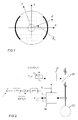
- Figure 1 is a simplified cross section of a salient pole rotor;
- Figure 2 is a block diagram of oscillating signal injection;
- Figure 3 is a block diagram of a prior art manner to estimate the angular speed and the position angle of a rotor on the basis of an error signal;
- Figure 4 shows a combination of a voltage model and signal injection in accordance with the invention;
- Figure 5 shows a control system arranged to control a permanent magnet synchronous machine with the combination of the voltage model and the signal injection in accordance with the invention.
-
- In the following, there is first described in detail a voltage model known per se, then signal injection known per se and finally a combination of these two, which constitutes a method of the invention.
- As mentioned above, in a flux observer based on a voltage model the flux and the speed are estimated from a stator voltage and a measured stator current. The voltage model is based on a motor voltage equation, which in connection with a solid rotor synchronous machine is expressed as
- In the voltage model the estimate of the permanent magnet flux in the stator coordinates is, at its simplest, just a time integral of the back EMF estimate
- Let us translate the voltage equation (1) to rotor coordinates to obtainwhere u s is stator voltage in rotor coordinates, i s is a stator current in rotor coordinates, ωm is the electrical angular speed of the rotor and ψpm is the amplitude of the permanent magnet flux. In the model created on a permanent magnet synchronous machine, on which model the voltage model is based, the permanent magnet flux does not actually change. Because the voltage model is based on the estimation of the back EMF, an estimate is calculated for a time derivative of the permanent magnet flux and thereby a dynamic value of the permanent magnet flux, which value is further used for calculating a speed estimate. The estimate of the back EMF in the rotor coordinates is written as

- Solved from the voltage equation (5) in the rotor coordinates the back EMF estimate is
- In the case of a salient pole synchronous machine an estimate of stator inductance must be replaced by d- and q-axial inductance estimates L and d and L andq. By dividing the complex back EMF estimate (7) into components and by replacing the stator inductance are obtained the terms
- The voltage model does not require the electrical angular speed of the rotor for flux estimation, so the method is sensorless. The motor parameters necessary for estimation include estimates for stator resistance R ands and in the case of the salient pole machine estimates for inductances L and d and L andq.
- The voltage model is based on an open loop integration. This is not good, however, because if the quantity to be integrated has a mean, as generally is the case with erroneous parameters, for instance, the integral is not stable and continuously increases its value. Thus, the integral needs to be compensated or replaced, for instance, by low-pass filtering.
- The voltage model can be modified in a variety of ways. One modification is described in the publication "Vector control of induction motor without shaft encoder", IEEE Transactions on Industry Applications, Vol, 28, No. 1, January/February 1992, pp. 157-164, by T. Ohtani, N. Takada, K. Tanaka. This voltage model modification that has been found to work in connection with the method of the invention is represented, translated to rotor coordinates, in the equation
- As stated above, the flux observer based on the voltage model works well at high speeds, because the back EMF induced by the motor is high and the effect of erroneous parameters, if any, will remain small. At low speeds the voltage model will not work alone in the case of erroneous parameters.
- Anisotropy of the rotor of a permanent magnet machine can be detected from variables measured on the rotor. Injecting a signal that deviates from the fundamental wave into stator connectors produces an injection frequency response that includes information on the rotor position. The rotor position can thus be concluded from the injection frequency portion of the measured current or voltage. This method is known as signal injection. The excitation fed into the motor can be either voltage or current, whereby the response will be obtained from the measured current or voltage, respectively. In this method to be described in greater detail the signal injection method is a high-frequency (typically 500 to 1000 Hz) signal injection using voltage excitation.
- In the method described a high-frequency, oscillating voltage signal is applied to the d-axis of assumed rotor coordinates, whereby an injection frequency current can be detected on the q-axis of the assumed rotor coordinates when the position angle is erroneous. This method is described in greater detail in the publication by M. Corley and R. Lorenz in 1998: "Rotor position and velocity estimation for a salient-pole permanent magnet synchronous machine at standstill and high speeds", IEEE Transactions on Industry Applications, Vol. 34, No. 4, July/August 1998. Figure 1 shows a cross section of the rotor and the axes of the synchronous coordinates, when an estimated position angle is erroneous. In the figure,= andm - m is a rotor position angle error and the axes d' and q' are the axes of the estimated rotor coordinates.

- The voltage signal to be used in the signal injection is given by
- The signal thus oscillates at double injection frequency, and therefore it should be low-pass filtered prior to using it for estimating a position error. The mean of the demodulated signal is the position tracking signal
- When the position angle error is small it can be assumed that the tracking signal is directly proportional to the position angle error in accordance with the expression
- Figure 2 shows a schematic block diagram of the oscillating signal injection. This block diagram shows a stator voltage reference u s , ref to be applied to a frequency converter, to the d component of which is added a signal ûc cos(ωct). The machine 23 is controlled with a frequency converter 24 to implement the voltage reference and the stator current of the machine is determined. It is shown in Figure 2 how demodulation is implemented by multiplying the stator current q component portion, filtered with a band-pass filter BPF, by sin(ω ct) and further by low-pass filtering the product obtained with a low-pass filter LPF. Figure 2 also shows coordinate translation blocks 21, 22, by which the voltage reference is translated from the assumed rotor coordinates to assumed stator coordinates and correspondingly the measured current from the stator coordinates to the assumed rotor coordinates. At the low-pass filter output there will be a position tracking signal ε that can be used for the determination of the angular speed and position angle of the rotor.
- Estimates of the rotor speed and position can be produced from the error signal obtained by the signal injection by means of a phase-locked loop as described in the publication by L. Harnefors, H. Nee in 2000: " A general algorithm for speed and position estimation of ac motors", IEEE Transactions on Industrial Electronics, Vol. 47, No. 1, February 2000, pp.77-83. From the difference obtained by the signal injection there is formed an estimated electrical angular speed of the rotor by integration. An estimated position angle is obtained by integrating the estimated electrical angular speed, to which is added the difference multiplied by the coefficient portion of the controller. The method is not based on the mechanical model of the motor.
- A block diagram of a controller forming speed and position estimates is shown in Figure 3. The input of this controller is the position tracking signal ε. When the position is erroneous, i.e. when the tracking signal deviates from zero, an amplifier 31 amplifies the signal with Ki , whereafter the amplified signal is integrated with an
integrator 32. Simultaneously the position tracking signal ε is amplified with anamplifier 33, and the signal multiplied by Kp is summed with a summingmeans 34 to the output signal of theintegrator 32. The summed signal is further integrated with anintegrator 35, whereby there is obtained an estimate on the rotor position angle andm. Correspondingly, the output of theintegrator 32 forms an angular speed estimate ω and m . Thus, the controller operates such that the position angle estimate and m obtained from the output is to be corrected to correspond to the actual position angle, whereby the position tracking signal ε is zeroed. - Figure 4 shows a combination of a voltage model and signal injection, which implements the method of the invention. In the method of the invention there is created a voltage model 41 on a permanent magnet synchronous machine. This voltage model is advantageously a modified voltage model similar to those presented in formulas (13) and (14). The voltage model may, however, be a standard voltage model presented in formulas (10) and (11), or any modification of machine flux equations that will provide a desired final result.
- The invention further comprises forming a voltage reference for a permanent magnet machine stator, determining stator currents of the permanent magnet synchronous machine and calculating a rotor angular speed from the voltage reference and the stator currents by using the voltage model. The formed voltage reference corresponds to the voltage of the machine stator poles so there will be no need to measure the stator voltage directly. In the voltage model it is possible, however, to use the measured voltage if need be. The method thus calculates the angular speed of the synchronous machine rotor on the basis of the above-described voltage model, which uses the stator voltage u s and the stator current i s as initial values. These variables are given in the assumed rotor coordinates, i.e. in the coordinates whose angular speed in relation to the stator is determined by the method in accordance with the invention.
- In accordance with the invention signal injection is used for forming a rotor position tracking signal ε of the permanent magnet synchronous machine, the formation of which signal is described above with reference to Figure 2. Figure 4 shows how the position tracking signal ε , the stator voltage u s and the stator current i s are applied as inputs to the block diagram determining the angular speed.
- The invention further comprises forming a rotor angular speed estimate ω andm from the rotor
angular speed 42, calculated by the voltage model 41, and the rotor position tracking signal ε and forming a rotor position angle estimate andm from the formed rotor angular speed estimate ω and m and the rotor position tracking signal ε. - In accordance with a preferred embodiment of the invention the rotor angular speed estimate is formed from the rotor
angular speed 42 and the rotor position tracking signal ε with a control circuit such that the tracking signal ε is amplified with anamplifier 43 by multiplying it by a coefficient Ki and by integrating by an integrator 44. The integrated signal is summed with a summing means 45 to the rotorangular speed 42 from the voltage model to obtain a rotor angular speed estimate ω and m . - Further, in accordance with a preferred embodiment of the invention a rotor position angle estimate and m is formed by integrating the sum of the formed angular speed estimate ω and m and the position tracking signal ε multiplied with the
amplifier 46. - In principle the block diagram of Figure 4 operates such that to the angular speed obtained from the voltage model is summed integral of a difference produced by signal injection. At the same time to this sum, i.e. the angular speed estimate ω and m , is added with the summing means 47 the position tracking signal ε multiplied by Kp. The output of the summing
means 47 is further integrated with theintegrator 48 to obtain a position angle estimate and m . - The rotor position tracking signal is zero if the rotor position angle estimate and m is precisely equal to the actual rotor position. If this is a steady state, i.e. the estimate remains correct, the angular speed estimate is also equal to the actual value. The block diagram of Figure 4 forms a control loop, in which a change in the actual speed in relation to the estimate and a change in the actual angle in relation to the estimate causes a value change in the estimates and finally the estimates become equal to the actual values. In other words, the position tracking signal always approaches as closely as possible to zero. This takes place in such a manner that the position tracking signal is summed to the value obtainable from the voltage model and corrects the value closer to the actual value.
- Because the tracking signal contains high-frequency noise and a strong injection frequency component, the signal must be low-pass filtered. In order to make a low-pass filter and a controller connected to the voltage model operate correctly, the transfer function of the closed loop of the position estimate should be solved. When the low-pass filter of the first order is taken into account, the transfer function of the closed loop is obtained by
- In Figure 5, the
speed controller 51 is given a speed reference ωm , ref , which compares the reference with the angular speed estimate ω and m determined in accordance with the method. In the embodiment of Figure 5 from the speed controller output is obtained a torque reference Te,ref, which is applied to a currentreference calculating block 52. The current reference i s , ref is calculated on the basis of said torque reference and the flux estimate ψ and pm determined by theflux observer 55 in a manner known per se. The current reference is further applied to thecurrent controller 53, whose other input is the determined stator current actual value i s . In the embodiment of Figure 5 the current controller output is a stator voltage reference u s,ref , which is used both for controlling themotor 58 with afrequency converter 59 and for input of theflux observer 55 as described above. Prior to controlling the frequency converter with the stator voltage reference it is divided into d and q components for implementing signal injection. Thesignal injection block 56 adds to the d component of the stator voltage reference a high-frequency signal that is further demodulated from the determined stator current. - The control system of Figure 5 works in assumed rotor coordinates, so both the stator voltage reference and the measured stator current should be translated between the coordinates using coordinate
translation blocks flux observer 55 includes a control circuit of Figure 4 that implements the method of the invention. - It is obvious to a person skilled in the art that as technology advances the basic idea of the invention can be implemented in a variety of ways. The invention and the embodiments thereof are thus not restricted to the above examples, but they may vary within the scope of the claims.
Claims (5)
- A method for determining the speed and position of a rotor of a salient-pole permanent magnet synchronous machine, the method comprising:creating a voltage model (41) on a permanent magnet synchronous machine;forming a voltage reference (us,ref) for a stator of the permanent magnet synchronous machine;determining stator currents (is) of the permanent magnet synchronous machine;calculating a rotor angular speed (42) from the voltage reference (us,ref) and the stator currents (is) using the voltage model (41), characterized in that the method further comprises:forming with signal injection a position tracking signal (ε)of the rotor of the permanent magnet synchronous machine;forming an rotor angular speed estimate (ω and m ) from the calculated rotor angular speed (42) and the rotor position tracking signal (ε);forming a rotor position angle estimate ( and m) from the formed rotor angular speed estimate (ω andm ) and the rotor position tracking signal (ε) .
- A method as claimed in claim 1, characterized in that the formation of the rotor angular speed estimate comprises a step, in which the amplified position tracking signal is integrated and summed to the calculated rotor angular speed.
- A method as claimed in claim 2, characterized in that the formation of the rotor position angle estimate comprises:summing the amplified position tracking signal to the angular speed estimate andintegrating the obtained sum.
- A method as claimed in any one of the preceding claims 1 to 3, characterized in that the signal injection is implemented in the d component of the voltage reference by adding thereto an oscillating signal, whereby the position tracking signal (ε) is demodulated from the q component of the determined stator current.
- A method as claimed in any one of the preceding claims 1 to 4, characterized in that the voltage model is a modified voltage model.
Applications Claiming Priority (2)
| Application Number | Priority Date | Filing Date | Title |
|---|---|---|---|
| FI20031267 | 2003-09-05 | ||
| FI20031267A FI115873B (en) | 2003-09-05 | 2003-09-05 | Method in connection with an open pole permanent magnet synchronous machine |
Publications (4)
| Publication Number | Publication Date |
|---|---|
| EP1513250A2 true EP1513250A2 (en) | 2005-03-09 |
| EP1513250A9 EP1513250A9 (en) | 2005-11-30 |
| EP1513250A3 EP1513250A3 (en) | 2006-11-02 |
| EP1513250B1 EP1513250B1 (en) | 2010-03-31 |
Family
ID=27838940
Family Applications (1)
| Application Number | Title | Priority Date | Filing Date |
|---|---|---|---|
| EP04103992A Active EP1513250B1 (en) | 2003-09-05 | 2004-08-20 | Method in salient-pole permanent magnet synchronous machine |
Country Status (5)
| Country | Link |
|---|---|
| US (1) | US7221152B2 (en) |
| EP (1) | EP1513250B1 (en) |
| AT (1) | ATE463074T1 (en) |
| DE (1) | DE602004026256D1 (en) |
| FI (1) | FI115873B (en) |
Cited By (5)
| Publication number | Priority date | Publication date | Assignee | Title |
|---|---|---|---|---|
| EP1841056A1 (en) * | 2006-03-29 | 2007-10-03 | JTEKT Corporation | A motor controller |
| EP1843461A2 (en) * | 2006-04-07 | 2007-10-10 | Sanyo Electric Co., Ltd. | Motor control device |
| EP1868288A1 (en) * | 2006-06-15 | 2007-12-19 | ABB Oy | Method and system in connection with permanent magnet synchronous machines |
| WO2020244954A1 (en) | 2019-06-04 | 2020-12-10 | Renault S.A.S | Method for estimating the electomagnetic torque of a synchronous electric machine |
| FR3106894A1 (en) | 2020-02-04 | 2021-08-06 | Renault S.A.S | Method for estimating the electromagnetic torque of a synchronous electric machine |
Families Citing this family (12)
| Publication number | Priority date | Publication date | Assignee | Title |
|---|---|---|---|---|
| JP4674525B2 (en) * | 2005-10-13 | 2011-04-20 | 株式会社デンソー | Magnetic pole position estimation method and motor control apparatus |
| DE102006052434B4 (en) * | 2006-11-07 | 2009-04-02 | Siemens Ag | Drive system for synchronized operation of several synchronous motors |
| EP1944860B9 (en) * | 2007-01-12 | 2010-10-20 | ABB Oy | A method for sensorless estimation of rotor speed and position of a permanent magnet synchronous machine |
| US20100237817A1 (en) | 2009-03-23 | 2010-09-23 | Jingbo Liu | Method and Apparatus for Estimating Rotor Position in a Sensorless Synchronous Motor |
| KR101470025B1 (en) * | 2009-07-06 | 2014-12-15 | 현대자동차주식회사 | A model based sensorless vector control method of PMSM using an adaptive observer |
| WO2011129423A1 (en) * | 2010-04-17 | 2011-10-20 | 日本電産株式会社 | Rotor phase/velocity estimation device for alternating-current motor |
| WO2013016505A2 (en) * | 2011-07-27 | 2013-01-31 | Carrier Corporation | Method for smooth motor startup |
| CN102347726A (en) * | 2011-09-15 | 2012-02-08 | 河北工业大学 | Device and method for observing rotor position in motor control |
| CN106788071B (en) * | 2017-01-06 | 2019-01-29 | 南京航空航天大学 | A method of improving permanent-magnet synchronous motor rotor position estimated accuracy |
| EP3826169B1 (en) | 2019-11-25 | 2023-12-13 | KOSTAL Drives Technology GmbH | Method and device for controlling a synchronous machine without a position sensor by means of a unique allocation of the flow linkage to the rotor position |
| CN111722156A (en) * | 2020-06-29 | 2020-09-29 | 深圳市优必选科技股份有限公司 | Detection circuit and detection method for positive and negative electrodes of brush motor and steering engine |
| CN113890449A (en) * | 2021-09-28 | 2022-01-04 | 北京泓慧国际能源技术发展有限公司 | Motor control method and device and electronic equipment |
Citations (4)
| Publication number | Priority date | Publication date | Assignee | Title |
|---|---|---|---|---|
| US5565752A (en) * | 1993-12-22 | 1996-10-15 | Wisconsin Alumni Research Foundation | Method and apparatus for transducerless position and velocity estimation in drives for AC machines |
| US6163127A (en) * | 1999-11-22 | 2000-12-19 | General Motors Corporation | System and method for controlling a position sensorless permanent magnet motor |
| US6492788B1 (en) * | 2000-11-10 | 2002-12-10 | Otis Elevator Company | Method and apparatus for encoderless operation of a permanent magnet synchronous motor in an elevator |
| US20030015987A1 (en) * | 2001-07-10 | 2003-01-23 | Dal-Ho Cheong | Apparatus and method for controlling rotation speed of synchronous reluctance motor |
Family Cites Families (8)
| Publication number | Priority date | Publication date | Assignee | Title |
|---|---|---|---|---|
| JPH08280199A (en) | 1995-02-10 | 1996-10-22 | Nippon Soken Inc | Sensor-less controller for permanent-magnet field synchronous motor |
| JP3486326B2 (en) | 1997-06-23 | 2004-01-13 | トヨタ自動車株式会社 | Operation control method and device for synchronous motor |
| US6137258A (en) * | 1998-10-26 | 2000-10-24 | General Electric Company | System for speed-sensorless control of an induction machine |
| JP3454210B2 (en) | 1999-11-30 | 2003-10-06 | 株式会社日立製作所 | Position sensorless control method for synchronous motor |
| DE69908786T2 (en) * | 1999-12-15 | 2004-04-22 | Bien-Air Holding S.A. | Brushless motor with device for determining the rotor position |
| JP3695342B2 (en) | 2001-04-11 | 2005-09-14 | 株式会社日立製作所 | Electric motor control device |
| JP3668870B2 (en) | 2001-08-09 | 2005-07-06 | 株式会社日立製作所 | Synchronous motor drive system |
| JP4370754B2 (en) * | 2002-04-02 | 2009-11-25 | 株式会社安川電機 | Sensorless control device and control method for AC motor |
-
2003
- 2003-09-05 FI FI20031267A patent/FI115873B/en not_active IP Right Cessation
-
2004
- 2004-08-17 US US10/919,484 patent/US7221152B2/en not_active Expired - Fee Related
- 2004-08-20 EP EP04103992A patent/EP1513250B1/en active Active
- 2004-08-20 DE DE602004026256T patent/DE602004026256D1/en active Active
- 2004-08-20 AT AT04103992T patent/ATE463074T1/en not_active IP Right Cessation
Patent Citations (4)
| Publication number | Priority date | Publication date | Assignee | Title |
|---|---|---|---|---|
| US5565752A (en) * | 1993-12-22 | 1996-10-15 | Wisconsin Alumni Research Foundation | Method and apparatus for transducerless position and velocity estimation in drives for AC machines |
| US6163127A (en) * | 1999-11-22 | 2000-12-19 | General Motors Corporation | System and method for controlling a position sensorless permanent magnet motor |
| US6492788B1 (en) * | 2000-11-10 | 2002-12-10 | Otis Elevator Company | Method and apparatus for encoderless operation of a permanent magnet synchronous motor in an elevator |
| US20030015987A1 (en) * | 2001-07-10 | 2003-01-23 | Dal-Ho Cheong | Apparatus and method for controlling rotation speed of synchronous reluctance motor |
Non-Patent Citations (1)
| Title |
|---|
| AIHARA T ET AL: "Sensor-less torque control of salient-pole synchronous motor at zero speed operation" APPLIED POWER ELECTRONICS CONFERENCE AND EXPOSITION, 1997. APEC '97 CONFERENCE PROCEEDINGS 1997., TWELFTH ANNUAL ATLANTA, GA, USA 23-27 FEB. 1997, NEW YORK, NY, USA,IEEE, US, vol. 2, 23 February 1997 (1997-02-23), pages 715-720, XP010215741 ISBN: 0-7803-3704-2 * |
Cited By (11)
| Publication number | Priority date | Publication date | Assignee | Title |
|---|---|---|---|---|
| EP1841056A1 (en) * | 2006-03-29 | 2007-10-03 | JTEKT Corporation | A motor controller |
| US7772789B2 (en) | 2006-03-29 | 2010-08-10 | Jtekt Corporation | Motor controller |
| EP1843461A2 (en) * | 2006-04-07 | 2007-10-10 | Sanyo Electric Co., Ltd. | Motor control device |
| EP1843461A3 (en) * | 2006-04-07 | 2010-01-13 | Sanyo Electric Co., Ltd. | Motor control device |
| US7893639B2 (en) | 2006-04-07 | 2011-02-22 | Sanyo Electric Co., Ltd. | Motor control device |
| EP1868288A1 (en) * | 2006-06-15 | 2007-12-19 | ABB Oy | Method and system in connection with permanent magnet synchronous machines |
| US7560894B2 (en) | 2006-06-15 | 2009-07-14 | Abb Oy | Method and system in connection with permanent magnet synchronous machines |
| WO2020244954A1 (en) | 2019-06-04 | 2020-12-10 | Renault S.A.S | Method for estimating the electomagnetic torque of a synchronous electric machine |
| FR3097090A1 (en) | 2019-06-04 | 2020-12-11 | Renault S.A.S | Method for estimating the electromagnetic torque of a synchronous electric machine |
| FR3106894A1 (en) | 2020-02-04 | 2021-08-06 | Renault S.A.S | Method for estimating the electromagnetic torque of a synchronous electric machine |
| WO2021156202A1 (en) | 2020-02-04 | 2021-08-12 | Renault S.A.S | Method for estimating the electomagnetic torque of a synchronous electric machine |
Also Published As
| Publication number | Publication date |
|---|---|
| US7221152B2 (en) | 2007-05-22 |
| EP1513250A3 (en) | 2006-11-02 |
| FI20031267A (en) | 2005-03-06 |
| EP1513250B1 (en) | 2010-03-31 |
| EP1513250A9 (en) | 2005-11-30 |
| US20050052177A1 (en) | 2005-03-10 |
| FI115873B (en) | 2005-07-29 |
| ATE463074T1 (en) | 2010-04-15 |
| FI20031267A0 (en) | 2003-09-05 |
| DE602004026256D1 (en) | 2010-05-12 |
Similar Documents
| Publication | Publication Date | Title |
|---|---|---|
| US7098623B2 (en) | Method in connection with permanent magnet synchronous machines | |
| EP1513250A2 (en) | Method in salient-pole permanent magnet synchronous machine | |
| JP3529752B2 (en) | DC brushless motor rotor angle detector | |
| CN100583620C (en) | Rotor position presuming method and apparatus, motor control method and compressor | |
| WO2002078167A1 (en) | Method for estimating magnetic polar position of synchronous motor and its controller | |
| US20160141994A1 (en) | Motor drive system and motor control device | |
| CN108631680B (en) | Permanent magnet synchronous machine and method for determining position of motor by using vibration induction salient pole | |
| KR20010014334A (en) | Method for estimating induced electromotive force and speed of induction motor, method for correcting misalignment of shaft thereof, and induction motor controller | |
| CN105227010B (en) | A kind of permagnetic synchronous motor position-sensor-free position detection error harmonic pulse removing method | |
| CN107171610A (en) | Rotor position estimate method, rotor position estimate device and motor | |
| JP3707528B2 (en) | AC motor control method and control apparatus therefor | |
| CN111711398A (en) | Dynamic performance improvement method for permanent magnet synchronous motor position sensorless control system | |
| JP5109790B2 (en) | Control device for permanent magnet type synchronous motor | |
| Bist et al. | Sensorless control based on sliding mode observer for pmsm drive | |
| JP2003153582A (en) | Control method and controller of pm motor | |
| JP2002078391A (en) | Drive system of ac motor | |
| EP1255348A1 (en) | Method of controlling induction motor | |
| CN110661466B (en) | Quasi-proportional resonance adaptive observer and permanent magnet synchronous motor position estimation method | |
| KR101779613B1 (en) | On-line parameter correcting method for sensorless control of interior permanent magnet synchronous motor | |
| JP4032845B2 (en) | Control device for synchronous motor | |
| KR20020007050A (en) | Method and System for Sensorless Field Orientation Control of AC Motor | |
| JP3692085B2 (en) | Motor control method and apparatus | |
| CN110855206B (en) | Motor current limitation of permanent magnet synchronous motor | |
| Stasi et al. | Sensorless control of PM synchronous motors based on LKF estimation of rotor position | |
| CN111817617A (en) | Low-speed position-sensorless control method for permanent magnet synchronous motor for vehicle |
Legal Events
| Date | Code | Title | Description |
|---|---|---|---|
| PUAI | Public reference made under article 153(3) epc to a published international application that has entered the european phase |
Free format text: ORIGINAL CODE: 0009012 |
|
| AK | Designated contracting states |
Kind code of ref document: A2 Designated state(s): AT BE BG CH CY CZ DE DK EE ES FI FR GB GR HU IE IT LI LU MC NL PL PT RO SE SI SK TR |
|
| AX | Request for extension of the european patent |
Extension state: AL HR LT LV MK |
|
| PUAL | Search report despatched |
Free format text: ORIGINAL CODE: 0009013 |
|
| AK | Designated contracting states |
Kind code of ref document: A3 Designated state(s): AT BE BG CH CY CZ DE DK EE ES FI FR GB GR HU IE IT LI LU MC NL PL PT RO SE SI SK TR |
|
| AX | Request for extension of the european patent |
Extension state: AL HR LT LV MK |
|
| 17P | Request for examination filed |
Effective date: 20070206 |
|
| AKX | Designation fees paid |
Designated state(s): AT BE BG CH CY CZ DE DK EE ES FI FR GB GR HU IE IT LI LU MC NL PL PT RO SE SI SK TR |
|
| 17Q | First examination report despatched |
Effective date: 20081223 |
|
| GRAP | Despatch of communication of intention to grant a patent |
Free format text: ORIGINAL CODE: EPIDOSNIGR1 |
|
| RIC1 | Information provided on ipc code assigned before grant |
Ipc: H02P 21/14 20060101AFI20091026BHEP |
|
| GRAS | Grant fee paid |
Free format text: ORIGINAL CODE: EPIDOSNIGR3 |
|
| GRAA | (expected) grant |
Free format text: ORIGINAL CODE: 0009210 |
|
| AK | Designated contracting states |
Kind code of ref document: B1 Designated state(s): AT BE BG CH CY CZ DE DK EE ES FI FR GB GR HU IE IT LI LU MC NL PL PT RO SE SI SK TR |
|
| REG | Reference to a national code |
Ref country code: GB Ref legal event code: FG4D Ref country code: CH Ref legal event code: EP |
|
| REG | Reference to a national code |
Ref country code: IE Ref legal event code: FG4D |
|
| REF | Corresponds to: |
Ref document number: 602004026256 Country of ref document: DE Date of ref document: 20100512 Kind code of ref document: P |
|
| REG | Reference to a national code |
Ref country code: NL Ref legal event code: VDEP Effective date: 20100331 |
|
| PG25 | Lapsed in a contracting state [announced via postgrant information from national office to epo] |
Ref country code: AT Free format text: LAPSE BECAUSE OF FAILURE TO SUBMIT A TRANSLATION OF THE DESCRIPTION OR TO PAY THE FEE WITHIN THE PRESCRIBED TIME-LIMIT Effective date: 20100331 Ref country code: FI Free format text: LAPSE BECAUSE OF FAILURE TO SUBMIT A TRANSLATION OF THE DESCRIPTION OR TO PAY THE FEE WITHIN THE PRESCRIBED TIME-LIMIT Effective date: 20100331 Ref country code: PL Free format text: LAPSE BECAUSE OF FAILURE TO SUBMIT A TRANSLATION OF THE DESCRIPTION OR TO PAY THE FEE WITHIN THE PRESCRIBED TIME-LIMIT Effective date: 20100331 Ref country code: SI Free format text: LAPSE BECAUSE OF FAILURE TO SUBMIT A TRANSLATION OF THE DESCRIPTION OR TO PAY THE FEE WITHIN THE PRESCRIBED TIME-LIMIT Effective date: 20100331 |
|
| PG25 | Lapsed in a contracting state [announced via postgrant information from national office to epo] |
Ref country code: SE Free format text: LAPSE BECAUSE OF FAILURE TO SUBMIT A TRANSLATION OF THE DESCRIPTION OR TO PAY THE FEE WITHIN THE PRESCRIBED TIME-LIMIT Effective date: 20100331 Ref country code: RO Free format text: LAPSE BECAUSE OF FAILURE TO SUBMIT A TRANSLATION OF THE DESCRIPTION OR TO PAY THE FEE WITHIN THE PRESCRIBED TIME-LIMIT Effective date: 20100331 Ref country code: NL Free format text: LAPSE BECAUSE OF FAILURE TO SUBMIT A TRANSLATION OF THE DESCRIPTION OR TO PAY THE FEE WITHIN THE PRESCRIBED TIME-LIMIT Effective date: 20100331 Ref country code: ES Free format text: LAPSE BECAUSE OF FAILURE TO SUBMIT A TRANSLATION OF THE DESCRIPTION OR TO PAY THE FEE WITHIN THE PRESCRIBED TIME-LIMIT Effective date: 20100712 Ref country code: EE Free format text: LAPSE BECAUSE OF FAILURE TO SUBMIT A TRANSLATION OF THE DESCRIPTION OR TO PAY THE FEE WITHIN THE PRESCRIBED TIME-LIMIT Effective date: 20100331 Ref country code: CY Free format text: LAPSE BECAUSE OF FAILURE TO SUBMIT A TRANSLATION OF THE DESCRIPTION OR TO PAY THE FEE WITHIN THE PRESCRIBED TIME-LIMIT Effective date: 20100331 Ref country code: BE Free format text: LAPSE BECAUSE OF FAILURE TO SUBMIT A TRANSLATION OF THE DESCRIPTION OR TO PAY THE FEE WITHIN THE PRESCRIBED TIME-LIMIT Effective date: 20100331 |
|
| PG25 | Lapsed in a contracting state [announced via postgrant information from national office to epo] |
Ref country code: CZ Free format text: LAPSE BECAUSE OF FAILURE TO SUBMIT A TRANSLATION OF THE DESCRIPTION OR TO PAY THE FEE WITHIN THE PRESCRIBED TIME-LIMIT Effective date: 20100331 Ref country code: SK Free format text: LAPSE BECAUSE OF FAILURE TO SUBMIT A TRANSLATION OF THE DESCRIPTION OR TO PAY THE FEE WITHIN THE PRESCRIBED TIME-LIMIT Effective date: 20100331 |
|
| PG25 | Lapsed in a contracting state [announced via postgrant information from national office to epo] |
Ref country code: DK Free format text: LAPSE BECAUSE OF FAILURE TO SUBMIT A TRANSLATION OF THE DESCRIPTION OR TO PAY THE FEE WITHIN THE PRESCRIBED TIME-LIMIT Effective date: 20100331 Ref country code: PT Free format text: LAPSE BECAUSE OF FAILURE TO SUBMIT A TRANSLATION OF THE DESCRIPTION OR TO PAY THE FEE WITHIN THE PRESCRIBED TIME-LIMIT Effective date: 20100802 |
|
| PLBE | No opposition filed within time limit |
Free format text: ORIGINAL CODE: 0009261 |
|
| STAA | Information on the status of an ep patent application or granted ep patent |
Free format text: STATUS: NO OPPOSITION FILED WITHIN TIME LIMIT |
|
| 26N | No opposition filed |
Effective date: 20110104 |
|
| PG25 | Lapsed in a contracting state [announced via postgrant information from national office to epo] |
Ref country code: MC Free format text: LAPSE BECAUSE OF NON-PAYMENT OF DUE FEES Effective date: 20100831 |
|
| REG | Reference to a national code |
Ref country code: CH Ref legal event code: PL |
|
| PG25 | Lapsed in a contracting state [announced via postgrant information from national office to epo] |
Ref country code: LI Free format text: LAPSE BECAUSE OF NON-PAYMENT OF DUE FEES Effective date: 20100831 Ref country code: CH Free format text: LAPSE BECAUSE OF NON-PAYMENT OF DUE FEES Effective date: 20100831 |
|
| PG25 | Lapsed in a contracting state [announced via postgrant information from national office to epo] |
Ref country code: IE Free format text: LAPSE BECAUSE OF NON-PAYMENT OF DUE FEES Effective date: 20100820 |
|
| PG25 | Lapsed in a contracting state [announced via postgrant information from national office to epo] |
Ref country code: HU Free format text: LAPSE BECAUSE OF FAILURE TO SUBMIT A TRANSLATION OF THE DESCRIPTION OR TO PAY THE FEE WITHIN THE PRESCRIBED TIME-LIMIT Effective date: 20101001 Ref country code: BG Free format text: LAPSE BECAUSE OF FAILURE TO SUBMIT A TRANSLATION OF THE DESCRIPTION OR TO PAY THE FEE WITHIN THE PRESCRIBED TIME-LIMIT Effective date: 20100331 Ref country code: LU Free format text: LAPSE BECAUSE OF NON-PAYMENT OF DUE FEES Effective date: 20100820 |
|
| PG25 | Lapsed in a contracting state [announced via postgrant information from national office to epo] |
Ref country code: TR Free format text: LAPSE BECAUSE OF FAILURE TO SUBMIT A TRANSLATION OF THE DESCRIPTION OR TO PAY THE FEE WITHIN THE PRESCRIBED TIME-LIMIT Effective date: 20100331 |
|
| PG25 | Lapsed in a contracting state [announced via postgrant information from national office to epo] |
Ref country code: BG Free format text: LAPSE BECAUSE OF FAILURE TO SUBMIT A TRANSLATION OF THE DESCRIPTION OR TO PAY THE FEE WITHIN THE PRESCRIBED TIME-LIMIT Effective date: 20100630 |
|
| PG25 | Lapsed in a contracting state [announced via postgrant information from national office to epo] |
Ref country code: GR Free format text: LAPSE BECAUSE OF FAILURE TO SUBMIT A TRANSLATION OF THE DESCRIPTION OR TO PAY THE FEE WITHIN THE PRESCRIBED TIME-LIMIT Effective date: 20100331 |
|
| REG | Reference to a national code |
Ref country code: FR Ref legal event code: PLFP Year of fee payment: 13 |
|
| REG | Reference to a national code |
Ref country code: FR Ref legal event code: PLFP Year of fee payment: 14 |
|
| REG | Reference to a national code |
Ref country code: FR Ref legal event code: PLFP Year of fee payment: 15 |
|
| REG | Reference to a national code |
Ref country code: GB Ref legal event code: 732E Free format text: REGISTERED BETWEEN 20180823 AND 20180829 |
|
| REG | Reference to a national code |
Ref country code: DE Ref legal event code: R082 Ref document number: 602004026256 Country of ref document: DE Representative=s name: DOMPATENT VON KREISLER SELTING WERNER - PARTNE, DE Ref country code: DE Ref legal event code: R081 Ref document number: 602004026256 Country of ref document: DE Owner name: ABB SCHWEIZ AG, CH Free format text: FORMER OWNER: ABB OY, HELSINKI, FI |
|
| PGFP | Annual fee paid to national office [announced via postgrant information from national office to epo] |
Ref country code: FR Payment date: 20180725 Year of fee payment: 15 |
|
| PGFP | Annual fee paid to national office [announced via postgrant information from national office to epo] |
Ref country code: GB Payment date: 20180822 Year of fee payment: 15 |
|
| GBPC | Gb: european patent ceased through non-payment of renewal fee |
Effective date: 20190820 |
|
| PG25 | Lapsed in a contracting state [announced via postgrant information from national office to epo] |
Ref country code: FR Free format text: LAPSE BECAUSE OF NON-PAYMENT OF DUE FEES Effective date: 20190831 |
|
| PG25 | Lapsed in a contracting state [announced via postgrant information from national office to epo] |
Ref country code: GB Free format text: LAPSE BECAUSE OF NON-PAYMENT OF DUE FEES Effective date: 20190820 |
|
| PGFP | Annual fee paid to national office [announced via postgrant information from national office to epo] |
Ref country code: IT Payment date: 20230825 Year of fee payment: 20 |
|
| PGFP | Annual fee paid to national office [announced via postgrant information from national office to epo] |
Ref country code: DE Payment date: 20230821 Year of fee payment: 20 |