EP1514604A1 - Portable air filtration system - Google Patents
Portable air filtration system Download PDFInfo
- Publication number
- EP1514604A1 EP1514604A1 EP04077110A EP04077110A EP1514604A1 EP 1514604 A1 EP1514604 A1 EP 1514604A1 EP 04077110 A EP04077110 A EP 04077110A EP 04077110 A EP04077110 A EP 04077110A EP 1514604 A1 EP1514604 A1 EP 1514604A1
- Authority
- EP
- European Patent Office
- Prior art keywords
- air
- filtration system
- filter media
- set forth
- air filtration
- Prior art date
- Legal status (The legal status is an assumption and is not a legal conclusion. Google has not performed a legal analysis and makes no representation as to the accuracy of the status listed.)
- Withdrawn
Links
Images


Classifications
-
- B—PERFORMING OPERATIONS; TRANSPORTING
- B03—SEPARATION OF SOLID MATERIALS USING LIQUIDS OR USING PNEUMATIC TABLES OR JIGS; MAGNETIC OR ELECTROSTATIC SEPARATION OF SOLID MATERIALS FROM SOLID MATERIALS OR FLUIDS; SEPARATION BY HIGH-VOLTAGE ELECTRIC FIELDS
- B03C—MAGNETIC OR ELECTROSTATIC SEPARATION OF SOLID MATERIALS FROM SOLID MATERIALS OR FLUIDS; SEPARATION BY HIGH-VOLTAGE ELECTRIC FIELDS
- B03C3/00—Separating dispersed particles from gases or vapour, e.g. air, by electrostatic effect
- B03C3/32—Transportable units, e.g. for cleaning room air
-
- B—PERFORMING OPERATIONS; TRANSPORTING
- B03—SEPARATION OF SOLID MATERIALS USING LIQUIDS OR USING PNEUMATIC TABLES OR JIGS; MAGNETIC OR ELECTROSTATIC SEPARATION OF SOLID MATERIALS FROM SOLID MATERIALS OR FLUIDS; SEPARATION BY HIGH-VOLTAGE ELECTRIC FIELDS
- B03C—MAGNETIC OR ELECTROSTATIC SEPARATION OF SOLID MATERIALS FROM SOLID MATERIALS OR FLUIDS; SEPARATION BY HIGH-VOLTAGE ELECTRIC FIELDS
- B03C3/00—Separating dispersed particles from gases or vapour, e.g. air, by electrostatic effect
- B03C3/02—Plant or installations having external electricity supply
- B03C3/04—Plant or installations having external electricity supply dry type
- B03C3/14—Plant or installations having external electricity supply dry type characterised by the additional use of mechanical effects, e.g. gravity
- B03C3/155—Filtration
-
- B—PERFORMING OPERATIONS; TRANSPORTING
- B03—SEPARATION OF SOLID MATERIALS USING LIQUIDS OR USING PNEUMATIC TABLES OR JIGS; MAGNETIC OR ELECTROSTATIC SEPARATION OF SOLID MATERIALS FROM SOLID MATERIALS OR FLUIDS; SEPARATION BY HIGH-VOLTAGE ELECTRIC FIELDS
- B03C—MAGNETIC OR ELECTROSTATIC SEPARATION OF SOLID MATERIALS FROM SOLID MATERIALS OR FLUIDS; SEPARATION BY HIGH-VOLTAGE ELECTRIC FIELDS
- B03C3/00—Separating dispersed particles from gases or vapour, e.g. air, by electrostatic effect
- B03C3/34—Constructional details or accessories or operation thereof
- B03C3/38—Particle charging or ionising stations, e.g. using electric discharge, radioactive radiation or flames
Definitions
- the subject invention generally relates to a portable air filtration system for filtering air.
- the portable air filtration system of the subject invention is primarily for use in vehicles but may also be used to filter air in rooms of commercial and residential buildings.
- Air filtration systems are known in the art. Many of these air filtration systems utilize ionization to enhance efficiency of a filter used within the air filtration system. The air filtration systems of the prior art are deficient for a variety of reasons.
- the air filtration system disclosed in the '383 patent is also deficient because it requires two electrodes that are separate from one another, a control electrode 104 and a downstream ground electrode 106, for sufficient ionization. The requirement for this additional componentry is unnecessary. Therefore, the design for this air filtration system is not optimized and is unnecessarily expensive.
- many of the air filtration systems of the prior art are deficient in that they are not sufficiently portable. That is, many air filtration systems are heavy, bulky, and awkward. For example, many air filtration systems do not include a handle for conveniently carrying the air filtration system from vehicle to vehicle or from room to room. Other air filtration systems include a filter housing that is constructed of a metal which tends to add weight to the air filtration system and makes it heavy to carry.
- the air filtration system includes a filter housing, an intake fan, an ionizing mechanism, a filter media, and an electrode. More specifically, the filter housing includes an air inlet and an air outlet and defines a filtration chamber between the air inlet and the air outlet.
- the intake fan is disposed within the filter housing to move the air through the filtration chamber by drawing the air in through the air inlet and dispelling the air out through the air outlet.
- the ionizing mechanism which is disposed between the intake fan and the air outlet, ionizes particles within the air to a negative charge.
- the filter media is disposed between the ionizing mechanism and the air outlet for entrapping the particles.
- the electrode is disposed between the ionizing mechanism and the filter media. As a result, an electric field is established between the ionizing mechanism and the electrode adjacent to the filter media. Therefore, the filter media is not within the electric field.
- the electrode is electrically-connected to ground and to the filter media. The negative charge of the particles that are entrapped within the filter media is dissipated through the electrode.
- the subject invention provides a novel air filtration system that is safe. More specifically, because the filter media is not within the electric field, the filter media is not exposed to any arcing within the electric field and is not susceptible to catching fire. Furthermore, the air filtration system of the subject invention eliminates the need for a separate control electrode and ground electrode. Instead, this air filtration system simplifies the required componentry by integrating the control electrode and the ground electrode into a single electrode. This single electrode provides a plane for establishing the electric field with the ionizing mechanism and also provides a ground for dissipating charges in the filter media. It is also advantageous that the air filtration system of the subject invention is portable.
- a portable air filtration system is generally disclosed at 10.
- the portable air filtration system 10 of the subject invention is hereinafter referred to as the filtration system 10.
- the filtration system 10 is used to filter air in a vehicle.
- the filtration system 10 can be placed on a floor, on a seat, or on any other suitable surface within the vehicle.
- the filtration system 10 can be adapted to be secured on the surface by a standard safety restraint system, i.e., a seatbelt.
- a standard safety restraint system i.e., a seatbelt.
- the filtration system 10 of the subject invention may also be used to filter air in rooms of commercial and residential buildings.
- the filtration system 10 include a handle 12 that is integrated into the filter housing 14.
- the handle 12 enhances the portability of the filtration system 10.
- the filtration system 10 is mobile and can be conveniently moved from vehicle to vehicle or from room to room.
- the handle 12 can be integrated into a filter housing 14 simply by being a recess within the filter housing 14 that can be accessed by a hand.
- the handle 12 can be integrated into the filter housing 14 by extending, either in a fixed manner or in a pivotable manner, from the filter housing 14.
- the filtration system 10 includes a filter housing 14, an intake fan 16, an ionizing mechanism 18, a filter media 20, and an electrode 22. Each of these components are described additionally below.
- the filter housing 14 includes an air inlet 24 and an air outlet 26.
- the filter housing 14 also defines a filtration chamber 28 between the air inlet 24 and the air outlet 26.
- the air flows through the filtration chamber 28 where particles which are typically present in the air, such as dust, lint, pollen, allergens, and the like, are filtered.
- the filter housing 14 is plastic. That is, it is preferred that the filter housing 14 is made from a non-metal material that is either a thermoplastic or thermosetting polymeric material.
- the filtration system 10 is compact with the filter housing 14 having approximate dimensions of 390 x 190 x 170 mm. These dimensions can vary.
- the filtration system 10 of the subject invention provides a high level of clear air delivery rate (CADR) for such a compact unit.
- ACR clear air delivery rate
- the air inlet 24 is further defined as inlet louvers 30 and the air outlet 26 is further defined as outlet louvers 32. Both the inlet louvers 30 and the outlet louvers 32 are defined within the filter housing 14.
- At least one of the inlet louvers 30 and the outlet louvers 32 are adjustable.
- the outlet louvers 32 are adjustable.
- the inlet louvers 30 it is possible for the inlet louvers 30 to be adjustable also.
- the controllability i.e., the ability to manipulate an angle, of the outlet louvers 32, is important so air exhausted out from the filtration system 10 can be targeted at a level where most occupants of a vehicle inhale and exhale. It is estimated that this level is achieved by angling the outlet louvers 32 approximately 60° upward, assuming the filtration system 10 is positioned on the seat of the vehicle.
- the range of angle for the outlet louvers 32 is typically 60° to 90°.
- the intake fan 16 is disposed within the filter housing 14.
- the intake fan 16 moves the air through the filtration chamber 28 by drawing the air in through the air inlet 24 and dispelling the air out through the air outlet 26.
- the intake fan 16 is a centrifugal fan.
- a speed of the intake fan 16 can be controlled such that users of the filtration system 10 can select a desired amount of filtering with a desired amount of noise level.
- the filtration system 10 include an adjustment knob 34 that can be adjusted from low to high to control the speed of the intake fan 16.
- increasing the speed of the intake fan 16 draws more air in through the air inlet 24 to be filtered but produces more noise, and vice versa.
- the filtration system 10 preferably incorporates a pre-filter 36 between the air inlet 24 and the intake fan 16.
- the pre-filter 36 typically an activated carbon pre-filter, is primarily used to absorb odors present in the air as the air is drawn in through the air inlet 24.
- the ionizing mechanism 18 is disposed between the intake fan 16 and the air outlet 26. In this position, the ionizing mechanism 18 ionizes the particles within the air to a negative charge, i.e. a negative state.
- the ionizing mechanism 18 is further defined as a plurality of ionizing needles. More specifically, in the most preferred embodiment of the subject invention as disclosed in Figure 3, the plurality of ionizing needles is further defined as a first 38, second 40, third 42, and fourth 44 ionizing needle. Any suitable number of ionizing needles can be utilized without varying the scope of the subject invention.
- the filtration system 10 includes a high voltage power supply 46.
- the high voltage power supply 46 of the filtration system 10 is electrically-connected to the ionizing mechanism 18 and is electrically-connected to an energy source of the vehicle.
- the filtration system 10 includes an adapter 48.
- the adapter 48 extends from the high voltage power supply 46.
- This adapter 48 is designed to insert into a cigarette lighter, or other port, in the vehicle and to tap into the energy source, such as a 12V battery, of the vehicle.
- the filtration system 10 also includes a circuit that incorporates a unique shut-off feature to protect a charge of the battery of the vehicle.
- the high voltage power supply 46 of the filtration system 10 is operatively connected to an electrical system of the building, and a different adapter is utilized to plug into an electrical outlet.
- the high voltage power supply 46 supplies a high voltage, approximately -15kV, to the ionizing mechanism 18.
- this high voltage is at a very low amperage, less than 1 milliamp, such that less than 10 W of power is required overall.
- the filter media 20 is disposed between the ionizing mechanism 18 and the air outlet 26. Ultimately, the filter media 20 entraps the particles yet allows the air to pass through the filtration system 10. As described additionally below, the filter media 20 is an electrically-enhanced filter (EEF) media and preferably can be removed from the filter housing 14 for replacement purposes over time. With particular reference to the Figures, the filter media 20 includes an upstream side 50 and a downstream side 52. The upstream side 50 faces the air inlet 24 and the downstream side 52 faces the air outlet 26.
- Several different filter media 20 are suitable for use in the filtration system 10 of the subject invention including, but not limited to, woven filter media, non-woven filter media, and cellular filter media.
- the electrode 22 is disposed between the ionizing mechanism 18 and the filter media 20 to establish an electric field between the ionizing mechanism 18 and the electrode 22.
- the electric field that is established is adjacent to the filter media 20. That is, the filter media 20 is not actually within the electric field. As such, the particles within the air are ionized upstream of the filter media 20 and no fire and/or other safety hazard is present with the filtration system 10 of the subject invention.
- the electric field has a distance D, defined between the ionizing mechanism 18 and the electrode 22, that has been optimized to control an ionization current applied to the particles and to prevent ozone generation, which is an additional deficiency associated with the air filtration systems of the prior art.
- the distance D has been optimized to range from 35 to 60, preferably from 40 to 50, mm.
- the electrode 22 is electrically-connected to ground 54.
- the electrode 22 is also electrically-connected to the filter media 20 for dissipating, i.e., bleeding, the negative charge of the particles that become entrapped within the filter media 20. More specifically, the electrode 22 is electrically-connected to the upstream side 50 of the filter media 20. Therefore, the negative charge of the particles entrapped with the filter media 20 is dissipated through the upstream side 50. For the negative charge of the particles entrapped within the filter media 20 to dissipate to ground 54 through the electrode 22, it is important that the filter media 20 be slightly conductive.
- the filter media 20 is 'relatively' dielectric and is, therefore, a poor conductor as compared to the conductivity of the electrode 22, the filter media 20 still must possess some degree of conductivity for the charge to dissipate to ground 54 through the electrode 22.
- the electrode 22 is electrically-connected to the filter media 20. To establish this electrical connection, it is preferred that the electrode 22 is in direct contact with the filter media 20. However, it is to be understood that the electrode 22 is not required to be in direct contact with the filter media 20 for the electrical connection to be present. Instead, the electrode 22 may be spaced from the filter media 20 and may be indirectly electrically-connected to the filter media 20 in any other suitable manner such as, for example, relying on additional componentry.
- the electrode 22 With the electrode 22 in this position, i.e., upstream of the filter media 20, and with the electrode 22 electrically-connected to both ground 54 and the filter media 20, the electrode 22 is able to perform two functions.
- the electrode 22 of the subject invention provides a plane for establishing the electric field with the ionizing mechanism 18, which is normally the function of a discrete control electrode that is separate from a ground electrode.
- the electrode 22 of the subject invention provides a ground 54 for dissipating charges present in the filter media 20, which is normally the function of a discrete ground electrode that is separate from a control electrode. Because the electrode 22 of the subject invention integrates the function of the two separate electrodes present in the prior art, the filtration system 10 of the subj ect invention has simplified componentry.
- the electrode 22 is further defined as a conductive grid 56.
- the conductive grid 56 functioning as the electrode 22, is electrically-connected to the upstream side 50 of the filter media 20.
- the conductive grid 56 can be metallic, i.e., a conductive metal, or conductive plastic.
- the most preferred conductive grid 56 is aluminum.
- the conductive grid 56 is adhesively bonded to the filter media 20.
- a chemical adhesive that is conductive can be used to adhere and therefore electrically-connect the conductive grid 56 to the filter media 20.
- the electrode 22, and more specifically the conductive grid 56 can be electrically-connected to the filter media 20 in any other suitable manner including, but not limited to, using electrically conductive connectors and fasteners between the electrode 22 and the filter media 20.
- the electrode 22 is further defined as a conductive coating that is applied to the filter media 20. In this embodiment, the conductive coating is more specifically applied to the upstream side 50 of the filter media 20.
Abstract
Description
- The subject invention generally relates to a portable air filtration system for filtering air. The portable air filtration system of the subject invention is primarily for use in vehicles but may also be used to filter air in rooms of commercial and residential buildings.
- Air filtration systems are known in the art. Many of these air filtration systems utilize ionization to enhance efficiency of a filter used within the air filtration system. The air filtration systems of the prior art are deficient for a variety of reasons.
- One example of a prior art air filtration system is disclosed in United States Patent No. 4,940,470 to Jaisinghani et al. With particular reference to Figure 1 of the '470 patent, this air filtration system is deficient because the electrode E, a ground electrode, is positioned downstream from the filter F. As such, the filter F is disposed within the electric field that is established between the ionizing wires W and the electrode E. Ultimately, this particular air filtration system presents a safety hazard as the filter F may be exposed to arcing that occurs in the electric field. The filter F may catch fire, destroy the air filtration system, and be dangerous to users of the air filtration system.
- A further example of a prior art air filtration system is disclosed in United States Patent No. 5,403,383 also to Jaisinghani et al. With particular reference to Figure 1 of the '383 patent, this air filtration system is deficient for the same reason identified above with respect to the '470 patent. That is, the ground electrode 106 is positioned downstream from the filter 114 such that the filter 114 is disposed within the electric field that is established between the ionizing wires 110 and the ground electrode 106. This position of the ground electrode 106 presents the same safety issues described above, i.e., exposure of the filter 114 to arcing in the electric field. However, the air filtration system disclosed in the '383 patent is also deficient because it requires two electrodes that are separate from one another, a control electrode 104 and a downstream ground electrode 106, for sufficient ionization. The requirement for this additional componentry is unnecessary. Therefore, the design for this air filtration system is not optimized and is unnecessarily expensive. Finally, many of the air filtration systems of the prior art are deficient in that they are not sufficiently portable. That is, many air filtration systems are heavy, bulky, and awkward. For example, many air filtration systems do not include a handle for conveniently carrying the air filtration system from vehicle to vehicle or from room to room. Other air filtration systems include a filter housing that is constructed of a metal which tends to add weight to the air filtration system and makes it heavy to carry.
- Due to the various deficiencies associated with the air filtration systems of the prior art, including those described above, it is desirable to provide a novel air filtration system that is safe, portable, and has simplified componentry yet still achieves enhanced filtration of particles from air.
- A portable air filtration system for filtering air is disclosed. The air filtration system includes a filter housing, an intake fan, an ionizing mechanism, a filter media, and an electrode. More specifically, the filter housing includes an air inlet and an air outlet and defines a filtration chamber between the air inlet and the air outlet. The intake fan is disposed within the filter housing to move the air through the filtration chamber by drawing the air in through the air inlet and dispelling the air out through the air outlet. The ionizing mechanism, which is disposed between the intake fan and the air outlet, ionizes particles within the air to a negative charge. The filter media is disposed between the ionizing mechanism and the air outlet for entrapping the particles.
- The electrode is disposed between the ionizing mechanism and the filter media. As a result, an electric field is established between the ionizing mechanism and the electrode adjacent to the filter media. Therefore, the filter media is not within the electric field. In addition, the electrode is electrically-connected to ground and to the filter media. The negative charge of the particles that are entrapped within the filter media is dissipated through the electrode.
- Accordingly, the subject invention provides a novel air filtration system that is safe. More specifically, because the filter media is not within the electric field, the filter media is not exposed to any arcing within the electric field and is not susceptible to catching fire. Furthermore, the air filtration system of the subject invention eliminates the need for a separate control electrode and ground electrode. Instead, this air filtration system simplifies the required componentry by integrating the control electrode and the ground electrode into a single electrode. This single electrode provides a plane for establishing the electric field with the ionizing mechanism and also provides a ground for dissipating charges in the filter media. It is also advantageous that the air filtration system of the subject invention is portable.
- Other advantages of the present invention will be readily appreciated as the same becomes better understood by reference to the following detailed description when considered in connection with the accompanying drawings wherein:
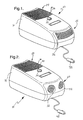
- Figure 1 is a perspective view of a portable air filtration system of the subject invention;
- Figure 2 is a perspective view of an alternative embodiment of the portable air filtration system illustrating adjustable louvers as an air outlet;
- Figure 3 is a partially cross-sectional perspective view of the portable air filtration system; and
- Figure 4 is a schematic representation of the portable air filtration system illustrating flow of air across an ionizing mechanism, an electric field, an electrode, and a filter media.
-
- Referring to the Figures, wherein like numerals indicate like or corresponding parts throughout the several views, a portable air filtration system is generally disclosed at 10. For descriptive purposes only, the portable
air filtration system 10 of the subject invention is hereinafter referred to as thefiltration system 10. - Preferably, the
filtration system 10 is used to filter air in a vehicle. In such an embodiment, thefiltration system 10 can be placed on a floor, on a seat, or on any other suitable surface within the vehicle. As such, thefiltration system 10 can be adapted to be secured on the surface by a standard safety restraint system, i.e., a seatbelt. However, thefiltration system 10 of the subject invention may also be used to filter air in rooms of commercial and residential buildings. - Although not required, it is most preferred that the
filtration system 10 include ahandle 12 that is integrated into thefilter housing 14. Thehandle 12 enhances the portability of thefiltration system 10. As such, thefiltration system 10 is mobile and can be conveniently moved from vehicle to vehicle or from room to room. As disclosed in Figure 3, thehandle 12 can be integrated into afilter housing 14 simply by being a recess within thefilter housing 14 that can be accessed by a hand. Alternatively, although not disclosed in the Figures, thehandle 12 can be integrated into thefilter housing 14 by extending, either in a fixed manner or in a pivotable manner, from thefilter housing 14. - Referring particularly to Figures 3 and 4, the
filtration system 10 includes afilter housing 14, an intake fan 16, anionizing mechanism 18, afilter media 20, and anelectrode 22. Each of these components are described additionally below. - The
filter housing 14 includes anair inlet 24 and anair outlet 26. Thefilter housing 14 also defines afiltration chamber 28 between theair inlet 24 and theair outlet 26. As schematically represented in Figure 4, the air flows through thefiltration chamber 28 where particles which are typically present in the air, such as dust, lint, pollen, allergens, and the like, are filtered. It is preferred that thefilter housing 14 is plastic. That is, it is preferred that thefilter housing 14 is made from a non-metal material that is either a thermoplastic or thermosetting polymeric material. To further enhance the transportability of thefiltration system 10, thefiltration system 10 is compact with thefilter housing 14 having approximate dimensions of 390 x 190 x 170 mm. These dimensions can vary. However, thefiltration system 10 of the subject invention provides a high level of clear air delivery rate (CADR) for such a compact unit. - Referring to one preferred embodiment disclosed in Figure 1, the
air inlet 24 is further defined asinlet louvers 30 and theair outlet 26 is further defined asoutlet louvers 32. Both theinlet louvers 30 and theoutlet louvers 32 are defined within thefilter housing 14. - Referring to the most preferred embodiment of the subject invention, as disclosed in Figure 2, at least one of the
inlet louvers 30 and theoutlet louvers 32 are adjustable. With thefiltration system 10 disclosed in Figure 2, only theoutlet louvers 32 are adjustable. Although it is not disclosed in the Figures, it is possible for theinlet louvers 30 to be adjustable also. - The controllability, i.e., the ability to manipulate an angle, of the
outlet louvers 32, is important so air exhausted out from thefiltration system 10 can be targeted at a level where most occupants of a vehicle inhale and exhale. It is estimated that this level is achieved by angling theoutlet louvers 32 approximately 60° upward, assuming thefiltration system 10 is positioned on the seat of the vehicle. The range of angle for theoutlet louvers 32 is typically 60° to 90°. - Referring to Figure 3, the intake fan 16 is disposed within the
filter housing 14. The intake fan 16 moves the air through thefiltration chamber 28 by drawing the air in through theair inlet 24 and dispelling the air out through theair outlet 26. Preferably, the intake fan 16 is a centrifugal fan. It is also preferred that a speed of the intake fan 16 can be controlled such that users of thefiltration system 10 can select a desired amount of filtering with a desired amount of noise level. As such, it is preferred that thefiltration system 10 include anadjustment knob 34 that can be adjusted from low to high to control the speed of the intake fan 16. Clearly, increasing the speed of the intake fan 16 draws more air in through theair inlet 24 to be filtered but produces more noise, and vice versa. - Furthermore, although it is not required, the
filtration system 10 preferably incorporates a pre-filter 36 between theair inlet 24 and the intake fan 16. The pre-filter 36, typically an activated carbon pre-filter, is primarily used to absorb odors present in the air as the air is drawn in through theair inlet 24. - The
ionizing mechanism 18 is disposed between the intake fan 16 and theair outlet 26. In this position, theionizing mechanism 18 ionizes the particles within the air to a negative charge, i.e. a negative state. Preferably, theionizing mechanism 18 is further defined as a plurality of ionizing needles. More specifically, in the most preferred embodiment of the subject invention as disclosed in Figure 3, the plurality of ionizing needles is further defined as a first 38, second 40, third 42, and fourth 44 ionizing needle. Any suitable number of ionizing needles can be utilized without varying the scope of the subject invention. - The
filtration system 10 includes a highvoltage power supply 46. The highvoltage power supply 46 of thefiltration system 10 is electrically-connected to theionizing mechanism 18 and is electrically-connected to an energy source of the vehicle. For example, as disclosed in Figures 1 and 2, thefiltration system 10 includes anadapter 48. Theadapter 48 extends from the highvoltage power supply 46. Thisadapter 48 is designed to insert into a cigarette lighter, or other port, in the vehicle and to tap into the energy source, such as a 12V battery, of the vehicle. It is preferred that thefiltration system 10 also includes a circuit that incorporates a unique shut-off feature to protect a charge of the battery of the vehicle. There is also a DC-DC power converter incorporated into the circuit for supplying power to thefiltration system 10. If thefiltration system 10 of the subject invention is to be used in the rooms of commercial and residential buildings, then the highvoltage power supply 46 of thefiltration system 10 is operatively connected to an electrical system of the building, and a different adapter is utilized to plug into an electrical outlet. To effectively ionize the particles within the air, the highvoltage power supply 46 supplies a high voltage, approximately -15kV, to theionizing mechanism 18. However, this high voltage is at a very low amperage, less than 1 milliamp, such that less than 10 W of power is required overall. - The
filter media 20 is disposed between theionizing mechanism 18 and theair outlet 26. Ultimately, thefilter media 20 entraps the particles yet allows the air to pass through thefiltration system 10. As described additionally below, thefilter media 20 is an electrically-enhanced filter (EEF) media and preferably can be removed from thefilter housing 14 for replacement purposes over time. With particular reference to the Figures, thefilter media 20 includes anupstream side 50 and adownstream side 52. Theupstream side 50 faces theair inlet 24 and thedownstream side 52 faces theair outlet 26. Severaldifferent filter media 20 are suitable for use in thefiltration system 10 of the subject invention including, but not limited to, woven filter media, non-woven filter media, and cellular filter media. - The
electrode 22 is disposed between theionizing mechanism 18 and thefilter media 20 to establish an electric field between theionizing mechanism 18 and theelectrode 22. The electric field that is established is adjacent to thefilter media 20. That is, thefilter media 20 is not actually within the electric field. As such, the particles within the air are ionized upstream of thefilter media 20 and no fire and/or other safety hazard is present with thefiltration system 10 of the subject invention. - The electric field has a distance D, defined between the
ionizing mechanism 18 and theelectrode 22, that has been optimized to control an ionization current applied to the particles and to prevent ozone generation, which is an additional deficiency associated with the air filtration systems of the prior art. The distance D has been optimized to range from 35 to 60, preferably from 40 to 50, mm. - As disclosed schematically in Figure 4, the
electrode 22 is electrically-connected to ground 54. Theelectrode 22 is also electrically-connected to thefilter media 20 for dissipating, i.e., bleeding, the negative charge of the particles that become entrapped within thefilter media 20. More specifically, theelectrode 22 is electrically-connected to theupstream side 50 of thefilter media 20. Therefore, the negative charge of the particles entrapped with thefilter media 20 is dissipated through theupstream side 50. For the negative charge of the particles entrapped within thefilter media 20 to dissipate to ground 54 through theelectrode 22, it is important that thefilter media 20 be slightly conductive. That is, although thefilter media 20 is 'relatively' dielectric and is, therefore, a poor conductor as compared to the conductivity of theelectrode 22, thefilter media 20 still must possess some degree of conductivity for the charge to dissipate to ground 54 through theelectrode 22. - As described above, the
electrode 22 is electrically-connected to thefilter media 20. To establish this electrical connection, it is preferred that theelectrode 22 is in direct contact with thefilter media 20. However, it is to be understood that theelectrode 22 is not required to be in direct contact with thefilter media 20 for the electrical connection to be present. Instead, theelectrode 22 may be spaced from thefilter media 20 and may be indirectly electrically-connected to thefilter media 20 in any other suitable manner such as, for example, relying on additional componentry. - With the
electrode 22 in this position, i.e., upstream of thefilter media 20, and with theelectrode 22 electrically-connected to bothground 54 and thefilter media 20, theelectrode 22 is able to perform two functions. First, theelectrode 22 of the subject invention provides a plane for establishing the electric field with theionizing mechanism 18, which is normally the function of a discrete control electrode that is separate from a ground electrode. Secondly, theelectrode 22 of the subject invention provides aground 54 for dissipating charges present in thefilter media 20, which is normally the function of a discrete ground electrode that is separate from a control electrode. Because theelectrode 22 of the subject invention integrates the function of the two separate electrodes present in the prior art, thefiltration system 10 of the subj ect invention has simplified componentry. - Referring particularly to Figures 3 and 4, the
electrode 22 is further defined as a conductive grid 56. The conductive grid 56, functioning as theelectrode 22, is electrically-connected to theupstream side 50 of thefilter media 20. The conductive grid 56 can be metallic, i.e., a conductive metal, or conductive plastic. The most preferred conductive grid 56 is aluminum. The conductive grid 56 is adhesively bonded to thefilter media 20. For example, a chemical adhesive that is conductive can be used to adhere and therefore electrically-connect the conductive grid 56 to thefilter media 20. Theelectrode 22, and more specifically the conductive grid 56, can be electrically-connected to thefilter media 20 in any other suitable manner including, but not limited to, using electrically conductive connectors and fasteners between theelectrode 22 and thefilter media 20. In an alternative embodiment of the subject invention, theelectrode 22 is further defined as a conductive coating that is applied to thefilter media 20. In this embodiment, the conductive coating is more specifically applied to theupstream side 50 of thefilter media 20. - The invention has been described in an illustrative manner, and it is to be understood that the terminology that has been used is intended to be in the nature of words of description rather than of limitation. Obviously, many modifications and variations of the present invention are possible in light of the above teachings. Therefore, it is to be understood that within the scope of the appended claims, the invention may be practiced otherwise than as specifically described.
Claims (24)
- A portable air filtration system 10 for filtering air, said filtration system 10 comprising:a filter housing 14 including an air inlet 24 and an air outlet 26 and defining a filtration chamber 28 between said air inlet 24 and said air outlet 26;an intake fan 16 disposed within said filter housing 14 for moving the air through said filtration chamber 28 by drawing the air in through said air inlet 24 and dispelling the air out through said air outlet 26;an ionizing mechanism 18 disposed between said intake fan 16 and said air outlet 26 for ionizing particles within the air to a negative charge;a filter media 20 disposed between said ionizing mechanism 18 and said air outlet 26 for entrapping the particles; andan electrode 22 disposed between said ionizing mechanism 18 and said filter media 20 to establish an electric field between said ionizing mechanism 18 and said electrode 22 adjacent to said filter media 20, wherein said electrode 22 is electrically-connected to ground 54 and to said filter media 20 for dissipating the negative charge of the particles entrapped within said filter media 20.
- An air filtration system 10 as set forth in claim 1 wherein said electrode 22 is spaced from said ionizing mechanism 18 such that said electric field has a distance defined between said electrode 22 and said ionizing mechanism 18 that ranges from 35 to 60 mm.
- An air filtration system 10 as set forth in claim 2 wherein said distance ranges from 40 to 50 mm.
- An air filtration system 10 as set forth in claim 1 wherein said filter media 20 comprises an upstream side 50 facing said air inlet 24 and a downstream side 52 facing said air outlet 26 with said electrode 22 being electrically-connected to said upstream side 50 of said filter media 20 for dissipating the negative charge of the particles entrapped with said filter media 20 through said upstream side 50.
- An air filtration system 10 as set forth in claim 1 further comprising a pre-filter 36 disposed between said air inlet 24 and said intake fan 16.
- An air filtration system 10 as set forth in claim 1 wherein said filter housing 14 is plastic.
- An air filtration system 10 as set forth in claim 1 wherein said filter media 20 is removable from said filter housing 14.
- An air filtration system 10 as set forth in claim 1 wherein said air inlet 24 is further defined as inlet louvers 30 defined within said filter housing 14.
- An air filtration system 10 as set forth in claim 1 wherein said air outlet 26 is further defined as outlet louvers 32 defined within said filter housing 14.
- An air filtration system 10 as set forth in claim 8 wherein said air outlet 26 is further defined as outlet louvers 32 defined within said filter housing 14.
- An air filtration system 10 as set forth in claim 10 wherein at least one of said inlet louvers 30 and said outlet louvers 32 are adjustable.
- An air filtration system 10 as set forth in claim 1 wherein said filter media 20 is further defined as a woven filter media 20.
- An air filtration system 10 as set forth in claim 1 wherein said filter media 20 is further defined as a non-woven filter media 20.
- An air filtration system 10 as set forth in claim 1 wherein said filter media 20 is further defined as a cellular filter media 20.
- An air filtration system 10 as set forth in claim 1 wherein said electrode 22 is further defined as a conductive grid 56.
- An air filtration system 10 as set forth in claim 15 wherein said conductive grid 56 is adhesively bonded to said filter media 20.
- An air filtration system 10 as set forth in claim 15 wherein said conductive grid 56 is plastic.
- An air filtration system 10 as set forth in claim 15 wherein said conductive grid 56 is metallic.
- An air filtration system 10 as set forth in claim 18 wherein said conductive grid 56 is aluminum.
- An air filtration system 10 as set forth in claim 4 wherein said electrode 22 is further defined as a conductive grid 56 electrically-connected to said upstream side 50 of said filter media 20.
- An air filtration system 10 as set forth in claim 1 wherein said ionizing mechanism 18 is further defined as a plurality of ionizing needles.
- An air filtration system 10 as set forth in claim 21 wherein said plurality of ionizing needles is further defined as a first 38, second 40, third 42, and fourth 44 ionizing needle.
- An air filtration system 10 as set forth in claim 1 further comprising a power supply 46 electrically-connected to said ionizing mechanism 18.
- An air filtration system 10 as set forth in claim 1 further comprising a handle 12 integrated into said filter housing 14 to enhance portability of said air filtration system 10.
Applications Claiming Priority (2)
| Application Number | Priority Date | Filing Date | Title |
|---|---|---|---|
| US647748 | 2003-08-25 | ||
| US10/647,748 US6989051B2 (en) | 2003-08-25 | 2003-08-25 | Portable air filtration system |
Publications (1)
| Publication Number | Publication Date |
|---|---|
| EP1514604A1 true EP1514604A1 (en) | 2005-03-16 |
Family
ID=34136613
Family Applications (1)
| Application Number | Title | Priority Date | Filing Date |
|---|---|---|---|
| EP04077110A Withdrawn EP1514604A1 (en) | 2003-08-25 | 2004-07-20 | Portable air filtration system |
Country Status (3)
| Country | Link |
|---|---|
| US (1) | US6989051B2 (en) |
| EP (1) | EP1514604A1 (en) |
| JP (1) | JP2005161302A (en) |
Cited By (1)
| Publication number | Priority date | Publication date | Assignee | Title |
|---|---|---|---|---|
| ITUD20120090A1 (en) * | 2012-05-16 | 2013-11-17 | Falmec S P A | AIR PURIFICATION DEVICE AND FILTERING EQUIPMENT INCLUDING THE PURIFICATION DEVICE |
Families Citing this family (30)
| Publication number | Priority date | Publication date | Assignee | Title |
|---|---|---|---|---|
| US7025806B2 (en) * | 2003-11-25 | 2006-04-11 | Stri{dot over (o)}nAir, Inc. | Electrically enhanced air filtration with improved efficacy |
| EP1632292A1 (en) * | 2004-09-03 | 2006-03-08 | DCT ApS | System with canopy and electrode for air cleaning |
| US7368003B2 (en) * | 2005-06-24 | 2008-05-06 | S.C. Johnson & Son, Inc. | Systems for and methods of providing air purification in combination with odor elimination |
| US7537647B2 (en) * | 2005-08-10 | 2009-05-26 | S.C. Johnson & Son, Inc. | Air purifier |
| US7452410B2 (en) * | 2005-12-17 | 2008-11-18 | Airinspace B.V. | Electrostatic filter having insulated electrodes |
| US8814994B2 (en) * | 2005-12-29 | 2014-08-26 | Environmental Management Confederation, Inc. | Active field polarized media air cleaner |
| US8795601B2 (en) | 2005-12-29 | 2014-08-05 | Environmental Management Confederation, Inc. | Filter media for active field polarized media air cleaner |
| US9789494B2 (en) | 2005-12-29 | 2017-10-17 | Environmental Management Confederation, Inc. | Active field polarized media air cleaner |
| US7789921B2 (en) * | 2006-05-30 | 2010-09-07 | S.C. Johnson & Son, Inc. | Portable devices for mitigating accumulation and localized settling of airborne particulates |
| US20090038480A1 (en) * | 2007-08-10 | 2009-02-12 | Hamilton Beach Brands, Inc. | Air purifier for removing particles or contaminants from air |
| CN101978116A (en) * | 2007-12-17 | 2011-02-16 | 代尔夫特科技大学 | Use of an electric field for the removal of droplets in a gaseous fluid |
| WO2010021712A1 (en) | 2008-08-20 | 2010-02-25 | S. C. Johnson & Son, Inc. | Dust prevention and removal device |
| JP5693295B2 (en) * | 2011-02-28 | 2015-04-01 | 三菱重工業株式会社 | CO2 recovery device and operation control method of CO2 recovery device |
| USD746967S1 (en) * | 2013-12-18 | 2016-01-05 | Samsung Electronics Co., Ltd. | Steam cleaner |
| US9808754B2 (en) | 2014-02-14 | 2017-11-07 | Access Business Group International Llc | Air treatment system |
| US9821260B2 (en) | 2014-02-14 | 2017-11-21 | Access Business Group International Llc | Air treatment system |
| USD846105S1 (en) | 2014-02-14 | 2019-04-16 | Access Business Group International Llc | Air treatment system |
| USD802725S1 (en) | 2014-02-14 | 2017-11-14 | Access Business Group International Llc | Air treatment system |
| EP2908064B1 (en) | 2014-02-18 | 2020-02-12 | Blueair AB | Air purifier device with ionizing means |
| EP2908067B1 (en) | 2014-02-18 | 2022-04-13 | Blueair AB | Air purifier device with coupling mechanism |
| EP3822555A1 (en) | 2014-02-18 | 2021-05-19 | Blueair AB | Air purifier device with fan duct |
| AU2015349900B2 (en) * | 2014-11-20 | 2018-11-29 | Environmental Management Confederation, Inc. | High voltage connection for sparse material |
| CA3056313C (en) | 2015-04-14 | 2023-04-04 | Environmental Management Confederation, Inc. | Corrugated filtration media for polarizing air cleaner |
| JP6941598B2 (en) | 2015-08-25 | 2021-09-29 | アルナイラム ファーマシューティカルズ, インコーポレイテッドAlnylam Pharmaceuticals, Inc. | Methods and Compositions for Treating Proprotein Convertase Subtilisin / Kexin (PCSK9) Gene-Related Disorders |
| GB2533466A (en) * | 2015-10-22 | 2016-06-22 | Darwin Tech Int Ltd | Air cleaning device |
| US20170354980A1 (en) * | 2016-06-14 | 2017-12-14 | Pacific Air Filtration Holdings, LLC | Collecting electrode |
| JP2018089585A (en) * | 2016-12-05 | 2018-06-14 | 三星電子株式会社Samsung Electronics Co.,Ltd. | Filter medium, air cleaning filter, hybrid air cleaning filter and air cleaner |
| USD825046S1 (en) | 2017-01-09 | 2018-08-07 | Access Business Group International Llc | Air treatment system |
| USD919070S1 (en) * | 2020-04-29 | 2021-05-11 | Dirk Niedermann | Portable air treatment unit |
| FR3131223A1 (en) | 2021-12-27 | 2023-06-30 | Fabrice Mendez | Filter for the removal of harmful particles from gaseous media |
Citations (6)
| Publication number | Priority date | Publication date | Assignee | Title |
|---|---|---|---|---|
| US3191362A (en) * | 1962-02-05 | 1965-06-29 | Knapp Monarch Co | Electrostatic air purifier |
| GB1559629A (en) * | 1976-04-29 | 1980-01-23 | Nissan Motor | Electrostatic precipitator |
| US4354858A (en) * | 1980-07-25 | 1982-10-19 | General Electric Company | Method for filtering particulates |
| JPS6287262A (en) * | 1985-10-11 | 1987-04-21 | Mitsubishi Electric Corp | Air cleaner |
| US5133788A (en) * | 1990-04-10 | 1992-07-28 | Backus Alan L | Air filtering device |
| WO1998020979A1 (en) * | 1996-11-08 | 1998-05-22 | Joannou Constantinos J | Externally ionizing air filter |
Family Cites Families (28)
| Publication number | Priority date | Publication date | Assignee | Title |
|---|---|---|---|---|
| CH629684A5 (en) * | 1977-05-12 | 1982-05-14 | Manfred R Burger | METHOD AND ELECTROSTATIC FILTER DEVICE FOR PURIFYING GASES. |
| US4357151A (en) * | 1981-02-25 | 1982-11-02 | American Precision Industries Inc. | Electrostatically augmented cartridge type dust collector and method |
| JPS59199063A (en) * | 1983-04-27 | 1984-11-12 | Mitsubishi Heavy Ind Ltd | Electrical dust precipitator |
| JPS62123251U (en) * | 1986-01-29 | 1987-08-05 | ||
| US4749390A (en) * | 1987-02-26 | 1988-06-07 | Air Purification Products, International | Four-sided air filter |
| US4768423A (en) * | 1987-06-03 | 1988-09-06 | Boeger Glen D | Vehicle charcoal air filter assembly |
| JPS6456848U (en) * | 1987-09-30 | 1989-04-10 | ||
| US4940470A (en) * | 1988-03-23 | 1990-07-10 | American Filtrona Corporation | Single field ionizing electrically stimulated filter |
| JPH0386047U (en) * | 1989-12-19 | 1991-08-30 | ||
| RU2026751C1 (en) * | 1992-05-13 | 1995-01-20 | Елена Владимировна Володина | Device for sterilization and fine gas filtration |
| US5403383A (en) * | 1992-08-26 | 1995-04-04 | Jaisinghani; Rajan | Safe ionizing field electrically enhanced filter and process for safely ionizing a field of an electrically enhanced filter |
| US5268009A (en) * | 1992-12-22 | 1993-12-07 | Teledyne Industries, Inc. | Portable air filter system |
| JPH06218215A (en) * | 1993-01-26 | 1994-08-09 | Toshiba Corp | Air cleaner |
| US5433772A (en) * | 1993-10-15 | 1995-07-18 | Sikora; David | Electrostatic air filter for mobile equipment |
| US5549735C1 (en) * | 1994-06-09 | 2001-08-14 | Coppom Technologies | Electrostatic fibrous filter |
| JP3445372B2 (en) * | 1994-07-25 | 2003-09-08 | 日本バイリーン株式会社 | Charged filter |
| JPH09239289A (en) * | 1996-03-05 | 1997-09-16 | Aten:Kk | Electrostatic air cleaner |
| JPH1071323A (en) * | 1996-08-30 | 1998-03-17 | Aqueous Res:Kk | Air cleaning filter and air cleaner for car |
| US5702507A (en) * | 1996-09-17 | 1997-12-30 | Yih Change Enterprise Co., Ltd. | Automatic air cleaner |
| US6056809A (en) * | 1996-10-18 | 2000-05-02 | Rick L. Chapman | High efficiency permanent air filter and method of manufacture |
| JPH11104516A (en) * | 1997-10-07 | 1999-04-20 | Calsonic Corp | Electrostatic type air cleaner |
| DE19852386C2 (en) * | 1998-11-13 | 2000-10-26 | Freudenberg Carl Fa | Filters for gaseous media |
| JP2001009326A (en) * | 1999-06-28 | 2001-01-16 | Ricoh Co Ltd | Air cleaner |
| US6391093B1 (en) * | 2000-01-24 | 2002-05-21 | Delphi Technologies, Inc. | Welding filtration system |
| US6355095B1 (en) * | 2000-05-22 | 2002-03-12 | Huang Kuo-Long | DC/AC air cleaner for a vehicle |
| US6491743B1 (en) * | 2000-09-11 | 2002-12-10 | Constantinos J. Joannou | Electronic cartridge filter |
| US6497754B2 (en) * | 2001-04-04 | 2002-12-24 | Constantinos J. Joannou | Self ionizing pleated air filter system |
| US6790259B2 (en) * | 2003-01-16 | 2004-09-14 | Blueair Ab | Method and device for cleaning a gaseous fluid using a conductive grid between charging head and filter |
-
2003
- 2003-08-25 US US10/647,748 patent/US6989051B2/en not_active Expired - Fee Related
-
2004
- 2004-07-20 EP EP04077110A patent/EP1514604A1/en not_active Withdrawn
- 2004-08-25 JP JP2004244592A patent/JP2005161302A/en active Pending
Patent Citations (6)
| Publication number | Priority date | Publication date | Assignee | Title |
|---|---|---|---|---|
| US3191362A (en) * | 1962-02-05 | 1965-06-29 | Knapp Monarch Co | Electrostatic air purifier |
| GB1559629A (en) * | 1976-04-29 | 1980-01-23 | Nissan Motor | Electrostatic precipitator |
| US4354858A (en) * | 1980-07-25 | 1982-10-19 | General Electric Company | Method for filtering particulates |
| JPS6287262A (en) * | 1985-10-11 | 1987-04-21 | Mitsubishi Electric Corp | Air cleaner |
| US5133788A (en) * | 1990-04-10 | 1992-07-28 | Backus Alan L | Air filtering device |
| WO1998020979A1 (en) * | 1996-11-08 | 1998-05-22 | Joannou Constantinos J | Externally ionizing air filter |
Non-Patent Citations (1)
| Title |
|---|
| PATENT ABSTRACTS OF JAPAN vol. 0112, no. 97 (C - 448) 25 September 1987 (1987-09-25) * |
Cited By (2)
| Publication number | Priority date | Publication date | Assignee | Title |
|---|---|---|---|---|
| ITUD20120090A1 (en) * | 2012-05-16 | 2013-11-17 | Falmec S P A | AIR PURIFICATION DEVICE AND FILTERING EQUIPMENT INCLUDING THE PURIFICATION DEVICE |
| EP2664857A1 (en) | 2012-05-16 | 2013-11-20 | Falmec S.P.A. | Hood filter |
Also Published As
| Publication number | Publication date |
|---|---|
| JP2005161302A (en) | 2005-06-23 |
| US20050045037A1 (en) | 2005-03-03 |
| US6989051B2 (en) | 2006-01-24 |
Similar Documents
| Publication | Publication Date | Title |
|---|---|---|
| US6989051B2 (en) | Portable air filtration system | |
| US7008469B2 (en) | Portable air filtration system utilizing a conductive coating and a filter for use therein | |
| US5846302A (en) | Electrostatic air filter device | |
| EP2318144B1 (en) | Apparatus, system, and method for enhancing air purification efficiency | |
| US20100307332A1 (en) | Supercharged electrostatic air filtration device | |
| KR101678237B1 (en) | Air cleaning apparatus | |
| CN110958891A (en) | Electric filter device | |
| JP2015150558A (en) | Air purifier device with ionizing means | |
| CA2613444A1 (en) | Systems for and methods of providing air purification in combination with odor elimination | |
| JP2005055114A (en) | Air cleaner | |
| JP4889386B2 (en) | Vacuum cleaner | |
| WO2006022852A1 (en) | Portable air purifier | |
| CN111684210B (en) | Air treatment device for ventilation air inlet | |
| EP1652587A2 (en) | Air conditioner with electrostatic dust collector | |
| CN205462733U (en) | Ionization formula air purification device | |
| CN105536991A (en) | Ionization-type air purification device | |
| KR102331353B1 (en) | Air-conditioning and air-cleaning equipment | |
| CN106765579A (en) | The purifier and cabinet-type air conditioner of air-conditioner | |
| JP7196550B2 (en) | air purifier | |
| US20050142045A1 (en) | Vehicular Photoelectron air purifier | |
| CN218379821U (en) | Ion generator, filtering component and air conditioner | |
| CN219843264U (en) | Ion generator and air purifier | |
| CN219415200U (en) | Portable ventilation device | |
| CN214841515U (en) | Device for eliminating virus and bacteria in air | |
| US20230048406A1 (en) | Ionic Personal Exhalant Filter |
Legal Events
| Date | Code | Title | Description |
|---|---|---|---|
| PUAI | Public reference made under article 153(3) epc to a published international application that has entered the european phase |
Free format text: ORIGINAL CODE: 0009012 |
|
| AK | Designated contracting states |
Kind code of ref document: A1 Designated state(s): AT BE BG CH CY CZ DE DK EE ES FI FR GB GR HU IE IT LI LU MC NL PL PT RO SE SI SK TR |
|
| AX | Request for extension of the european patent |
Extension state: AL HR LT LV MK |
|
| 17P | Request for examination filed |
Effective date: 20050916 |
|
| AKX | Designation fees paid |
Designated state(s): AT BE BG CH CY CZ DE DK EE ES FI FR GB GR HU IE IT LI LU MC NL PL PT RO SE SI SK TR |
|
| 17Q | First examination report despatched |
Effective date: 20090826 |
|
| STAA | Information on the status of an ep patent application or granted ep patent |
Free format text: STATUS: THE APPLICATION IS DEEMED TO BE WITHDRAWN |
|
| 18D | Application deemed to be withdrawn |
Effective date: 20100306 |