EP1516640A1 - Continuous high-frequency oscillation breathing treatment apparatus - Google Patents
Continuous high-frequency oscillation breathing treatment apparatus Download PDFInfo
- Publication number
- EP1516640A1 EP1516640A1 EP04022326A EP04022326A EP1516640A1 EP 1516640 A1 EP1516640 A1 EP 1516640A1 EP 04022326 A EP04022326 A EP 04022326A EP 04022326 A EP04022326 A EP 04022326A EP 1516640 A1 EP1516640 A1 EP 1516640A1
- Authority
- EP
- European Patent Office
- Prior art keywords
- gas
- flow
- aperture
- aerosol
- patient
- Prior art date
- Legal status (The legal status is an assumption and is not a legal conclusion. Google has not performed a legal analysis and makes no representation as to the accuracy of the status listed.)
- Granted
Links
- 230000029058 respiratory gaseous exchange Effects 0.000 title claims abstract description 72
- 230000010355 oscillation Effects 0.000 title claims abstract description 40
- 239000000443 aerosol Substances 0.000 claims abstract description 35
- 239000006199 nebulizer Substances 0.000 claims description 34
- 230000009467 reduction Effects 0.000 claims description 17
- 230000000541 pulsatile effect Effects 0.000 claims description 15
- 230000007423 decrease Effects 0.000 claims description 12
- 230000001105 regulatory effect Effects 0.000 claims description 12
- 238000002560 therapeutic procedure Methods 0.000 abstract description 36
- 230000028327 secretion Effects 0.000 abstract description 17
- 210000004072 lung Anatomy 0.000 abstract description 11
- 239000007789 gas Substances 0.000 description 104
- 239000003814 drug Substances 0.000 description 18
- 238000004891 communication Methods 0.000 description 14
- 230000003434 inspiratory effect Effects 0.000 description 8
- 210000003097 mucus Anatomy 0.000 description 6
- 238000004519 manufacturing process Methods 0.000 description 5
- 239000003570 air Substances 0.000 description 4
- 229940079593 drug Drugs 0.000 description 4
- 230000007246 mechanism Effects 0.000 description 4
- 230000000694 effects Effects 0.000 description 3
- 238000000034 method Methods 0.000 description 3
- 230000008569 process Effects 0.000 description 3
- 230000001225 therapeutic effect Effects 0.000 description 3
- 238000009423 ventilation Methods 0.000 description 3
- 208000019693 Lung disease Diseases 0.000 description 2
- 238000013461 design Methods 0.000 description 2
- 238000010586 diagram Methods 0.000 description 2
- 208000015181 infectious disease Diseases 0.000 description 2
- 239000007788 liquid Substances 0.000 description 2
- 230000000420 mucociliary effect Effects 0.000 description 2
- 230000002685 pulmonary effect Effects 0.000 description 2
- 210000002345 respiratory system Anatomy 0.000 description 2
- 230000000717 retained effect Effects 0.000 description 2
- 238000012549 training Methods 0.000 description 2
- 102000007469 Actins Human genes 0.000 description 1
- 108010085238 Actins Proteins 0.000 description 1
- 241000894006 Bacteria Species 0.000 description 1
- 101100110009 Caenorhabditis elegans asd-2 gene Proteins 0.000 description 1
- 206010011224 Cough Diseases 0.000 description 1
- 239000012080 ambient air Substances 0.000 description 1
- QVGXLLKOCUKJST-UHFFFAOYSA-N atomic oxygen Chemical compound [O] QVGXLLKOCUKJST-UHFFFAOYSA-N 0.000 description 1
- 230000002238 attenuated effect Effects 0.000 description 1
- 230000008901 benefit Effects 0.000 description 1
- 239000006227 byproduct Substances 0.000 description 1
- 230000001684 chronic effect Effects 0.000 description 1
- 230000010405 clearance mechanism Effects 0.000 description 1
- 230000007123 defense Effects 0.000 description 1
- 230000003292 diminished effect Effects 0.000 description 1
- 238000005516 engineering process Methods 0.000 description 1
- 230000005713 exacerbation Effects 0.000 description 1
- 230000002349 favourable effect Effects 0.000 description 1
- 230000001771 impaired effect Effects 0.000 description 1
- 238000002347 injection Methods 0.000 description 1
- 239000007924 injection Substances 0.000 description 1
- 208000020816 lung neoplasm Diseases 0.000 description 1
- 238000012423 maintenance Methods 0.000 description 1
- 239000000463 material Substances 0.000 description 1
- 239000000203 mixture Substances 0.000 description 1
- 230000001483 mobilizing effect Effects 0.000 description 1
- 230000003534 oscillatory effect Effects 0.000 description 1
- 239000001301 oxygen Substances 0.000 description 1
- 229910052760 oxygen Inorganic materials 0.000 description 1
- 230000000630 rising effect Effects 0.000 description 1
- 238000007789 sealing Methods 0.000 description 1
- 230000032258 transport Effects 0.000 description 1
Images


Classifications
-
- A—HUMAN NECESSITIES
- A61—MEDICAL OR VETERINARY SCIENCE; HYGIENE
- A61M—DEVICES FOR INTRODUCING MEDIA INTO, OR ONTO, THE BODY; DEVICES FOR TRANSDUCING BODY MEDIA OR FOR TAKING MEDIA FROM THE BODY; DEVICES FOR PRODUCING OR ENDING SLEEP OR STUPOR
- A61M16/00—Devices for influencing the respiratory system of patients by gas treatment, e.g. mouth-to-mouth respiration; Tracheal tubes
- A61M16/0096—High frequency jet ventilation
-
- A—HUMAN NECESSITIES
- A61—MEDICAL OR VETERINARY SCIENCE; HYGIENE
- A61M—DEVICES FOR INTRODUCING MEDIA INTO, OR ONTO, THE BODY; DEVICES FOR TRANSDUCING BODY MEDIA OR FOR TAKING MEDIA FROM THE BODY; DEVICES FOR PRODUCING OR ENDING SLEEP OR STUPOR
- A61M16/00—Devices for influencing the respiratory system of patients by gas treatment, e.g. mouth-to-mouth respiration; Tracheal tubes
- A61M16/0003—Accessories therefor, e.g. sensors, vibrators, negative pressure
- A61M16/0006—Accessories therefor, e.g. sensors, vibrators, negative pressure with means for creating vibrations in patients' airways
-
- A—HUMAN NECESSITIES
- A61—MEDICAL OR VETERINARY SCIENCE; HYGIENE
- A61M—DEVICES FOR INTRODUCING MEDIA INTO, OR ONTO, THE BODY; DEVICES FOR TRANSDUCING BODY MEDIA OR FOR TAKING MEDIA FROM THE BODY; DEVICES FOR PRODUCING OR ENDING SLEEP OR STUPOR
- A61M16/00—Devices for influencing the respiratory system of patients by gas treatment, e.g. mouth-to-mouth respiration; Tracheal tubes
- A61M16/08—Bellows; Connecting tubes ; Water traps; Patient circuits
- A61M16/0816—Joints or connectors
- A61M16/0833—T- or Y-type connectors, e.g. Y-piece
-
- A—HUMAN NECESSITIES
- A61—MEDICAL OR VETERINARY SCIENCE; HYGIENE
- A61M—DEVICES FOR INTRODUCING MEDIA INTO, OR ONTO, THE BODY; DEVICES FOR TRANSDUCING BODY MEDIA OR FOR TAKING MEDIA FROM THE BODY; DEVICES FOR PRODUCING OR ENDING SLEEP OR STUPOR
- A61M16/00—Devices for influencing the respiratory system of patients by gas treatment, e.g. mouth-to-mouth respiration; Tracheal tubes
- A61M16/10—Preparation of respiratory gases or vapours
- A61M16/12—Preparation of respiratory gases or vapours by mixing different gases
- A61M16/122—Preparation of respiratory gases or vapours by mixing different gases with dilution
- A61M16/125—Diluting primary gas with ambient air
- A61M16/127—Diluting primary gas with ambient air by Venturi effect, i.e. entrainment mixers
-
- A—HUMAN NECESSITIES
- A61—MEDICAL OR VETERINARY SCIENCE; HYGIENE
- A61M—DEVICES FOR INTRODUCING MEDIA INTO, OR ONTO, THE BODY; DEVICES FOR TRANSDUCING BODY MEDIA OR FOR TAKING MEDIA FROM THE BODY; DEVICES FOR PRODUCING OR ENDING SLEEP OR STUPOR
- A61M11/00—Sprayers or atomisers specially adapted for therapeutic purposes
- A61M11/06—Sprayers or atomisers specially adapted for therapeutic purposes of the injector type
Definitions
- the invention relates to a therapeutic breathing device which delivers continuous high-frequency oscillation therapy during both inhalation and exhalation to facilitate the removal of mucus secretions from the lungs.
- U.S. Pat Nos. 4,592,349, 4,805,613, 4,838,260, 4,930,501, 5, 007, 420, 5,116,088, 5,165,398, and 5, 862, 802 describe ventilators that combine high-frequency oscillation gas flow with aerosol.
- these ventilators are designed primarily for life support, they connect to the patient via patient adapters that incorporate relatively complex mechanized valves that open and close between phasic shifts from inhalation to exhalation.
- U.S. Pat No. 4,592,349 describes a "pneumatic clutching means" as an exhalation valve assembly with a venturi slidably mounted within in such a way as to move between open and closed positions.
- the sliding venturi patient adapter is too complex, bulky, and costly to manufacture to be included in a simple, inexpensive therapy device.
- the patient interface necessitates the fabrication of a number of moving parts made of a variety of materials.
- the resulting friction of the constant sliding between open and closed positions eventually fatigues valve components that must be replaced.
- the sliding venturi patient interface requires critical dimensions that prevent a reduction in its size and weight.
- the present invention is a simple apparatus for delivering continuous high-frequency oscillation therapy to the lungs during both inhalation and exhalation in order to assist in mucus secretion clearance. It comprises a pressurized gas source, a pressure reduction regulator, a flow interrupter, a nebulizer, and a fixed, open-aperture, shrouded venturi within the patient interface.
- an object of the present invention is to provide a continuous high-frequency oscillation breathing treatment device that can be manufactured simply and inexpensively.
- Another object of the invention is to provide a continuous high-frequency oscillation breathing treatment device that is sufficiently simple to use so that it requires little or no training.
- Another object of the present invention is to provide a continuous high-frequency oscillation breathing treatment device that delivers pulses to the patient and allows the patient to exhale into it without stacking successive volumes of gas in the airways.
- Another object of the invention is to provide a continuous high-frequency oscillation breathing treatment device that will be simple and inexpensive to maintain.
- Another object of the invention is to provide a continuous high-frequency oscillation breathing treatment device that maximizes safety during use.
- Another object of the invention is to provide a continuous high-frequency oscillation breathing treatment device that is sufficiently small and lightweight enough to be conveniently transported.
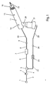
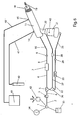
- FIG. 1 shows a schematic diagram of a continuous high-frequency oscillation breathing treatment apparatus comprising a source of pressurized gas attached to a source gas 1, a gas supply tube 2, a reduction regulator 3, a flow interrupter valve 7, and a patient interface circuit comprised of circuit tubes 10 and 25, a breathing head assembly 11 and a nebulizer 21.
- Source gas 1 connects to pressure reduction regulator 3 by means of a source gas supply tube 2.
- Pressure reduction regulator 3 is connected via small a bore (1/8" ID) tube 4 to connector tee 5.
- One end of connector tee 5 attaches to tube 22 and the other end of connector tee 5 attaches to tube 6.
- Circuit tube 25 connects by one end to circuit connector 24 and by the other end to nebulizer 21.
- Tube 6 connects by one end to connector tee 5 and by the other end to flow interrupter valve 7, for example, a pneumatic "logic cell cartridge", model A50146, manufactured by Percussionaire Corp.
- the other end of flow interrupter valve 7 is connected to tube 8 which connects to circuit connector 9.
- Circuit connector 9 connects to one end of circuit tube 10, and the other end of circuit tube 10 connects to the rearmost end of breathing head assembly 11.
- aft apertures 14 Located on top toward the rear of breathing head assembly 11 are aft apertures 14. Forward apertures 15 are positioned approximately three-fourths of the way toward the front of breathing head assembly 11. Mouthpiece 18 and mouthpiece opening 19 are at the front end of breathing head assembly 11. Nebulizer 21 is connected to aerosol entrainment port 20 located on the bottom toward the rear end of breathing head assembly 11.
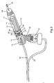
- FIG. 2 is a cross sectional side view in more detail of patient interface circuit comprising circuit tubes 10 and 25, breathing head assembly, mouthpiece 18, and nebulizer 21.
- Circuit tube 25 connects to the bottom of nebulizer 21, which, in turn, connects to aerosol entrainment port 20 located at the rearmost bottom portion of breathing head assembly 11.
- Circuit tube 10 connects to the rearmost end of breathing head assembly 11 by connecting directly to an injector nozzle 13 which is positioned in the rear portion of breathing head assembly 11.
- above injector nozzle 13 is at least one of aft apertures 14 which open the shell of breathing head assembly 11 to the ambient.
- a venturi tube 17 which is anchored in the rear by the annular support of rear venturi support flange 30 and near the middle of breathing head 11 by two forward venturi support flanges 28 and 29 in such a manner that the shell of breathing head assembly 11 functions as a shroud for venturi tube 17.
- Rear venturi support flange 30 contains several rear flange communication ports 16 which are longitudinal holes that perforate it circumferentially allowing communication between both sides of flange 30.
- forward venturi support flanges 28 and 29 are perforated circumferentially and longitudinally by several forward flange communication ports 26 and 27 allowing communication between both sides of each of flanges 28 and 29.
- forward apertures 15 which open the interior of breathing head assembly 11 shell to atmosphere.
- the forward portion of venturi tube 17 is sufficiently separated from the sides of breathing head assembly 11 shell so as to allow a circumferential communication space 12 which completes a communication corridor which extends from the rearmost cavity of breathing head assembly 11 through mouthpiece 18 and mouthpiece opening 19.
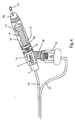
- FIG. 3 is a cross sectional top view in more detail of a patient interface circuit comprising circuit tubes 10 and 25, breathing head assembly 11, nebulizer 21, and mouthpiece 18.
- Circuit tube 25 connects to the bottom of nebulizer 21.
- Circuit tube 10 connects to the rearmost end of breathing head assembly 11 by connecting directly to injector nozzle 13 which is positioned in the rearmost portion of breathing head assembly 11. This top view shows placement of aft apertures 14 and forward apertures 15, which open shell of breathing head assembly 11 to the ambient.
- Operation of the breathing treatment apparatus begins by loading a predetermined liquid medicament into nebulizer 21 by first detaching it from aerosol entrainment port 20. After filled nebulizer 21 is reattached, therapy is initiated by turning on source gas 1, which may be a compressor within the device, or an external pressurized gas source such as air or oxygen. Gas travels through source gas supply tube 2 into pressure reduction regulator 3 whereby it is modulated to a suitable constant flow. Reduction regulator 3 can be pre-set at the factory to a desirable flow in order to maximize the simplicity of the therapy. The regulated gas then flows through tube 4 to connector tee 5 which splits the gas into two streams.
- source gas which may be a compressor within the device, or an external pressurized gas source such as air or oxygen.
- Gas travels through source gas supply tube 2 into pressure reduction regulator 3 whereby it is modulated to a suitable constant flow.
- Reduction regulator 3 can be pre-set at the factory to a desirable flow in order to maximize the simplicity of the therapy.
- circuit connector 24 connects circuit tube 25 which carries gas to the bottom of nebulizer 21.
- Nebulizer 21 converts the liquid medication into aerosol which enters into aerosol entrainment port 20, ushering the aerosol into the rear cavity of breathing head assembly 11.
- Valve 7 chops the constant gas flow into high-frequency pulses by interrupting it at regular intervals so that the flow becomes divided into substantially equal volumes, or pulses, at the rate of 1 to 15 hertz. Valve 7 can be pre-set at the factory to a predetermined rate to maximize the simplicity of the therapy. Because the flow is constant and the pulses are substantially equal, the resulting pulsatile pressure amplitude is substantially constant. That is to say that the difference between the lowest pressure and the highest pressure of each pulse is substantially equal.
- Circuit connector 9 connects circuit tube 10 which carries the gas to the rearmost portion of breathing head assembly 11.
- the high-frequency pulses enter injector nozzle 13 which directs them into the rear opening of venturi tube 17.
- venturi tube 17 which may either amplify or attenuate it.
- venturi tube 17 As the flow enters venturi tube 17, given little or no resistance at mouthpiece opening 19, the flow is amplified.
- Additional gas then enters via aft aperture 14 by virtue of two processes. First, the increased velocity lowers surrounding pressures creating a vacuum effect, first described by Swiss mathematician Daniel Bernoulli in 1738, pulling in or entraining additional gas. Second, the friction between the highspeed molecules and the adjacent low-speed molecules has the effect of pulling the low-speed gas molecules into the stream of the highspeed gas.
- ambient gas is pulled into the rear cavity of breathing head assembly 11 through aft aperture 14 and aerosol entrainment port 20.
- the velocity of the gas increases, the volume of entrained gas increases, and, therefore, overall flow increases.
- the device allows the patient to exhale back into it, and the device is provided with a built-in safety mechanism.
- resistance. downstream from the venturi tube increases.
- the resulting decrease in delivered flow also decreases pressure, thereby protecting the airways and allowing the patient to exhale.
- the mixture of high-frequency pulsatile flow from injection nozzle 13, aerosol from port 20, and ambient air from aft entrainment apertures 14 continue through the lumen of venturi tube 17, exiting its forward opening into mouthpiece 18 and out mouthpiece opening 19 to the patient.
- the patient seals his or her lips around mouthpiece 18 and inhales the aerosolized pulses of gas, taking them deep into the lungs. The patient then exhales back into mouthpiece opening 19 as the therapy continues.
- the combination of aft apertures 14, forward apertures 15, rear flange communication ports 16, and forward flange communication ports 26 and 27 allow both ingress and egress of flow, serving both inhalation and exhalation without the need for complex mechanisms to open and close valves during the therapy.
- the medicated aerosol and the oscillation of the air column in the conducting airways help reduce viscosity of the secretions.
- the bi-level flow created by high-frequency intermittent delivery of gas begins to create wind shear forces. A small pulse enters the airways, and then the flow momentarily stops. During this pause, the pressure in the upper airways drops to zero. Small volumes of gas that were previously delivered into the airways now begin to exit, momentarily unencumbered by the zero-pressure in the upper airways. As these exiting volumes of gas increase in velocity they continually push secretions from small distal airways to the larger openings in the upper airways where they can be more easily removed.
- the intermittent positive-pressure pulses continue constantly as the patient inhales and exhales through mouthpiece opening 19.
- the exhaled breath travels from mouthpiece opening 19 into circumferential communication space 12 and exits forward apertures 15.
- Aft apertures 14 and forward apertures 15 are calibrated with flow interrupter 7 so that the patient is able to exhale back into mouthpiece opening 19 even as the high-frequency positive gas flow continues. This calibration allows ample opportunity for exhaled breath to escape in order to prevent the successive stacking of inhaled breaths in the airways.
- FIG. 4 depicts an alternate embodiment cross sectional side view of a patient interface circuit which includes within a means for interrupting positive gas flow for use with the continuous high-frequency oscillation breathing therapy apparatus of the present invention.
- Flow interrupter valve 7 is attached directly to the rearmost portion of breathing head assembly 11.
- Flow interrupter valve 7 chops the flow into high-frequency intermittent pulses which then go directly into injector nozzle 13 and continue the process as described above. This embodiment allows most of the elements of the apparatus to be included within the patient interface circuit itself.
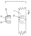
- FIG. 5 presents an alternate embodiment exploded sectional view of aft apertures 14 of breathing head assembly 11 with an annular aperture adjustment collar 31 to provide a means for partially occluding apertures 14 in order to increase and decrease the ingress and egress of flow.
- Each of aperture adjustment collar holes 32 is surrounded by a safety crown 33 to prevent inadvertent complete occlusion.
- Aperture adjustment collar 31 is slidably attached to breathing head assembly 11 adjacent to aft apertures 14 so that it can be axially adjusted.
- aperture adjustment collar 31 When aperture adjustment collar 31 is positioned so that aperture adjustment holes 32 align fully with aft apertures 14, maximum ingress and egress of flow is allowed.
- aperture adjustment collar 31 As aperture adjustment collar 31 is rotated so that aperture adjustment holes 32 begin to overlap aft apertures 14, effectively reducing the opening size of the apertures, ingress and egress of flow becomes more diminished.
- the peaks of safety crown 33 eliminate inadvertent complete occlusion of aperture adjustment collar holes 32 by preventing a finger or hand from sealing them.
- FIG. 5 The embodiment depicted in FIG. 5 is applicable to aft apertures 14, which may be designated as primary for ingress of flow, and forward apertures 15 (FIGS. 1,2,3, &4), which may be designated as primary for egress of flow.
- FIG. 6 is a schematic diagram of an alternate embodiment that includes a number of additional features incorporated into the continuous high-frequency oscillation breathing treatment device.
- Timer 34 is connected to source gas 1, as is patient compliance monitor 35 and RFID transceiver 42.
- Reservoir tee 36 connects tube 37 to tube 22. Tube 37 connects by the other end to medicament reservoir 38. Medicament reservoir 38 is in communication with nebulizer 21 via tube 39.
- Specified gas source 40 connects to one end of inspiratory gas connector 41. The other end of inspiratory gas connector 41 connects to aft apertures 14.
- RFID tag 43 is embedded into a plastic wall of nebulizer 21.
- Evacuation reservoir 49 connects to forward apertures 15 by means of evacuation reservoir tube 48.
- Timer 34 allows the clinician or the patient to pre-set a time for the treatment. At the end of the therapy session timer 34 can either turn off the apparatus by terminating source gas 1, or alarm to notify the patient that the treatment is over.
- Patient compliance monitor 35 logs use of the device in order to allow a clinician to determine whether or not the patient is utilizing the device.
- Medicament Reservoir 38 receives gas flow through tube 37, which is connected to tube 22 by reservoir tee 36. Medication is pumped from medicament reservoir 38 through tube 39 to nebulizer 21. This allows medication to be stored in a location remote from nebulizer 21, and medication can be continually pumped into nebulizer 21 as the therapy progresses.
- Aft apertures 14 may be designated as primary for inspiration.
- the content of inspired gas can be controlled by connecting specified gas source 40 to aft apertures 14 by way of inspiratory gas connector 41.
- Forward apertures 15 may be designated as primary for exhalation. In this case, apertures 15 can be left open to the ambient or can be connected to evacuation reservoir 49.
- RFID (Radio Frequency Identification) transceiver 42 connected to source gas 1, can recognize identification information transmitted from RFID tag 43, embedded in nebulizer 21, to determine whether or not the component is compatible with the apparatus.
- RFID transceiver 42 can be programmed to prevent gas source 1 from being initiated if a component is incompatible.
- FIG. 7 depicts a top-view perspective of an alternate embodiment of the continuous high-frequency oscillation apparatus that is incorporated into a ventilator breathing circuit.
- Ventilator circuit inspiratory limb 44 and ventilator circuit expiratory limb 45 are connected to ventilator circuit Y 46.
- breathing head assembly 11 Mounted within ventilator circuit inspiratory limb 44 is breathing head assembly 11, which is connected to the continuous high-frequency oscillation apparatus by circuit tube 10, which is also mounted within ventilator circuit inspiratory limb 44.
- the configuration presented in the alternate embodiment of FIG. 7 allows a treatment to be given to a patient connected to a ventilator without the need to disconnect the patient from the ventilator circuit.
Abstract
Description
- The invention relates to a therapeutic breathing device which delivers continuous high-frequency oscillation therapy during both inhalation and exhalation to facilitate the removal of mucus secretions from the lungs.
- Healthy people are able to clear mucus secretions from their lungs by means of bi-directional airflow and a system of tiny hair-like follicles called "mucociliary escalators." Airflow passing over the secretions creates shear forces that combine with the mucociliary escalators to transport mucus from the lower respiratory tract to upper airways. From there the secretions can be removed by coughing.
- However, during illness a person's normal ability to remove secretions may become impaired. As the natural secretion clearance mechanism becomes more challenged, secretions may build up in the lungs, bronchial and tracheal passages creating a heightened potential for further exacerbation of illness. Retained mucus secretions in the warm, moist environment of the lungs create an excellent opportunity for the growth of bacteria. In addition, retained secretions may hinder the lungs' ability to exchange gas and increase the risk of pulmonary neoplasm. Keeping the lungs open and clear of secretions is integral to maintaining a healthy defense of the pulmonary system.
- As the population ages, and the quality of air decreases, assaults on the respiratory system continue to rise. In addition to curable pulmonary infections, there are some 16 million people in the United States alone diagnosed with chronic lung disease, and it is estimated that an additional 16 million cases go undiagnosed. Associated costs in both healthcare and lost production hours are staggering.
- Because of the rising costs associated with pulmonary disease and the importance of keeping the lungs clear, clinicians and patients alike seek simple, inexpensive therapy devices that can enhance secretion mobilization. However, despite the variety of devices available, few show evidence of overall benefit.
- In the late 1970's a Swedish anesthesiologist pioneered the use of "high-frequency ventilation" for life support by programming a ventilator to deliver 60 breaths per minute, or 1 hertz. Subsequently the application of high-frequency delivery of gas to the airways was found to show favorable results in mobilizing secretions, especially when combined with medicated aerosol. While exact mechanisms of this therapy are not fully understood, it is likely that, as the column of air in the airways is oscillated by the high-frequency pulses of gas, the viscosity of the mucus is reduced by the untangling of some of the larger molecule strands, such as DNA and F-actin, which tend to be present as a byproduct of infection. Additionally, the high-frequency, intermittent delivery of gas contributes to a bi-directional flow creating wind shear forces which, in turn, help to mobilize the secretions in a cephalad fashion. However, in spite of therapeutic promise, the vast majority of those in need of this therapy do not have access to it because current technology is too complex and; therefore, ultimately too expensive.
- U.S. Pat Nos. 4,592,349, 4,805,613, 4,838,260, 4,930,501, 5, 007, 420, 5,116,088, 5,165,398, and 5, 862, 802 describe ventilators that combine high-frequency oscillation gas flow with aerosol. However, because these ventilators are designed primarily for life support, they connect to the patient via patient adapters that incorporate relatively complex mechanized valves that open and close between phasic shifts from inhalation to exhalation.
- U.S. Pat No. 4,592,349 describes a "pneumatic clutching means" as an exhalation valve assembly with a venturi slidably mounted within in such a way as to move between open and closed positions. Although highly effective in delivering life-support ventilation, the sliding venturi patient adapter is too complex, bulky, and costly to manufacture to be included in a simple, inexpensive therapy device. The patient interface necessitates the fabrication of a number of moving parts made of a variety of materials. The resulting friction of the constant sliding between open and closed positions eventually fatigues valve components that must be replaced. Additionally, the sliding venturi patient interface requires critical dimensions that prevent a reduction in its size and weight.
- Although an alternate embodiment of a patient adaptor to be used with the above devices described in U.S. Pat. No. 4,592,349 utilizes a fixed venturi, it, nonetheless, must incorporate or attach to a mechanical exhalation valve that opens and closes between inhalation and exhalation. This design, again, although effective in delivering life-support ventilation, renders the patient connector too complex and costly to be used in a simple, inexpensive breathing therapy device.
- In addition to being expensive because of their complexity of manufacturing and maintenance, the devices currently capable of delivering high-frequency oscillatory therapy to the lungs are complicated and difficult to use. They require either significant training of the patient or a trained professional to administer the therapy. U.S. Pat No. 4,592,349, cited above, also describes a simpler version of these life-support ventilators which is specifically intended for therapeutic use. However, even this simpler, scaled-down version is designed with a mechanism to terminate the delivery of gas during exhalation, as well as adjustments for both pressure and pulse frequency during a therapy session. This design renders the device both costly to manufacture and complex to use.
- The present invention is a simple apparatus for delivering continuous high-frequency oscillation therapy to the lungs during both inhalation and exhalation in order to assist in mucus secretion clearance. It comprises a pressurized gas source, a pressure reduction regulator, a flow interrupter, a nebulizer, and a fixed, open-aperture, shrouded venturi within the patient interface.
- Accordingly, an object of the present invention is to provide a continuous high-frequency oscillation breathing treatment device that can be manufactured simply and inexpensively.
- Another object of the invention is to provide a continuous high-frequency oscillation breathing treatment device that is sufficiently simple to use so that it requires little or no training.
- Another object of the present invention is to provide a continuous high-frequency oscillation breathing treatment device that delivers pulses to the patient and allows the patient to exhale into it without stacking successive volumes of gas in the airways.
- Another object of the invention is to provide a continuous high-frequency oscillation breathing treatment device that will be simple and inexpensive to maintain.
- Another object of the invention is to provide a continuous high-frequency oscillation breathing treatment device that maximizes safety during use.
- Another object of the invention is to provide a continuous high-frequency oscillation breathing treatment device that is sufficiently small and lightweight enough to be conveniently transported.
-
- FIG. 1 is a schematic representation of the continuous high-frequency oscillation breathing therapy apparatus of present invention;
- FIG. 2 is a cross sectional side view in more detail of a patient interface circuit for use with the continuous high-frequency oscillation breathing therapy apparatus of present invention;
- FIG. 3 is a cross sectional top view in more detail of a patient interface circuit for use with the continuous high-frequency oscillation breathing therapy apparatus of present invention;
- FIG. 4 is an alternate embodiment cross sectional side view of a patient interface circuit which includes within a means for interrupting positive gas flow for use with the breathing therapy apparatus of the present invention;
- FIG. 5 is an alternate embodiment exploded sectional view of the aft apertures of the patient interface circuit with a means for their partial occlusion, and a means to prevent inadvertent complete occlusion of the apertures;
- FIG. 6 is a schematic representation of an alternate embodiment of the continuous high-frequency oscillation breathing therapy apparatus of present invention; and
- FIG. 7 is a top view of an alternate embodiment of the patient circuit of the continuous high-frequency oscillation breathing therapy apparatus of present invention is incorporated within a ventilator circuit.
-
-
- 1
- Source Gas
- 2
- Source Gas Supply Tube
- 3
- Pressure Reduction Regulator
- 4
- Tube
- 5
- Connector Tee
- 6
- Tube
- 7
- Flow Interrupter
- 8
- Tube
- 9
- Circuit Connector
- 10
- Circuit Tube
- 11
- Breathing Head Assembly
- 12
- Circumferential Communication Space
- 13
- Injector Nozzle
- 14
- Aft Apertures
- 15
- Forward Apertures
- 16
- Rear Flange Communication Ports
- 17
- Venturi Tube
- 18
- Mouthpiece
- 19
- Mouthpiece Opening
- 20
- Aerosol Entrainment Port
- 21
- Nebulizer
- 22
- Tube
- 23
- Reducing Orifice
- 24
- Circuit Connector
- 25
- Circuit Tube
- 26
- Forward Flange Communications Ports
- 27
- Forward Flange Communications Ports
- 28
- Forward Venturi Support Flange
- 29
- Forward Venturi Support Flange
- 30
- Rear Venturi Support Flange
- 31
- Aperture Adjustment Collar
- 32
- Aperture Adjustment Collar Holes
- 33
- Safety Crowns
- 34
- Timer
- 35
- Patient Compliance Monitor
- 36
- Reservoir Tee
- 37
- Tube
- 38
- Medicament Reservoir
- 39
- Tube
- 40
- Specified Gas Source
- 41
- Inspiratory Gas Connector
- 42
- RFID Transceiver
- 43
- RFID Tag
- 44
- Ventilator Circuit Inspiratory Limb
- 45
- Ventilator Circuit Expiratory Limb
- 46
- Ventilator Circuit Y
- 47
- Ventilator Circuit Y Patient Connector
- 48
- Evacuation Reservoir Tube
- 49
- Evacuation Reservoir
- FIG. 1 shows a schematic diagram of a continuous high-frequency oscillation breathing treatment apparatus comprising a source of pressurized gas attached to a source gas 1, a
gas supply tube 2, areduction regulator 3, aflow interrupter valve 7, and a patient interface circuit comprised ofcircuit tubes breathing head assembly 11 and anebulizer 21. Source gas 1 connects to pressurereduction regulator 3 by means of a sourcegas supply tube 2.Pressure reduction regulator 3 is connected via small a bore (1/8" ID)tube 4 toconnector tee 5. One end ofconnector tee 5 attaches totube 22 and the other end ofconnector tee 5 attaches totube 6. - A
tube 22, which has within it a reducingorifice 23, connects by one end toconnector tee 5 and by the other end tocircuit connector 24.Circuit tube 25 connects by one end tocircuit connector 24 and by the other end tonebulizer 21. -
Tube 6 connects by one end toconnector tee 5 and by the other end to flowinterrupter valve 7, for example, a pneumatic "logic cell cartridge", model A50146, manufactured by Percussionaire Corp. The other end offlow interrupter valve 7 is connected totube 8 which connects tocircuit connector 9.Circuit connector 9 connects to one end ofcircuit tube 10, and the other end ofcircuit tube 10 connects to the rearmost end of breathinghead assembly 11. - Located on top toward the rear of breathing
head assembly 11 areaft apertures 14. Forward apertures 15 are positioned approximately three-fourths of the way toward the front of breathinghead assembly 11.Mouthpiece 18 and mouthpiece opening 19 are at the front end of breathinghead assembly 11.Nebulizer 21 is connected toaerosol entrainment port 20 located on the bottom toward the rear end of breathinghead assembly 11. - FIG. 2 is a cross sectional side view in more detail of patient interface circuit comprising
circuit tubes mouthpiece 18, andnebulizer 21.Circuit tube 25 connects to the bottom ofnebulizer 21, which, in turn, connects toaerosol entrainment port 20 located at the rearmost bottom portion of breathinghead assembly 11.Circuit tube 10 connects to the rearmost end of breathinghead assembly 11 by connecting directly to aninjector nozzle 13 which is positioned in the rear portion of breathinghead assembly 11. - In the rear portion of breathing
head assembly 11, aboveinjector nozzle 13 is at least one ofaft apertures 14 which open the shell of breathinghead assembly 11 to the ambient. Inside breathinghead assembly 11 is mounted aventuri tube 17 which is anchored in the rear by the annular support of rearventuri support flange 30 and near the middle of breathinghead 11 by two forwardventuri support flanges head assembly 11 functions as a shroud forventuri tube 17. Rearventuri support flange 30 contains several rearflange communication ports 16 which are longitudinal holes that perforate it circumferentially allowing communication between both sides offlange 30. Likewise, forwardventuri support flanges flange communication ports flanges head assembly 11 is at least one offorward apertures 15 which open the interior of breathinghead assembly 11 shell to atmosphere. The forward portion ofventuri tube 17 is sufficiently separated from the sides of breathinghead assembly 11 shell so as to allow acircumferential communication space 12 which completes a communication corridor which extends from the rearmost cavity of breathinghead assembly 11 throughmouthpiece 18 andmouthpiece opening 19. - FIG. 3 is a cross sectional top view in more detail of a patient interface circuit comprising
circuit tubes breathing head assembly 11,nebulizer 21, andmouthpiece 18.Circuit tube 25 connects to the bottom ofnebulizer 21.Circuit tube 10 connects to the rearmost end of breathinghead assembly 11 by connecting directly toinjector nozzle 13 which is positioned in the rearmost portion of breathinghead assembly 11. This top view shows placement ofaft apertures 14 andforward apertures 15, which open shell of breathinghead assembly 11 to the ambient. - Operation of the breathing treatment apparatus, pictured in Figs. 1, 2, and 3, begins by loading a predetermined liquid medicament into
nebulizer 21 by first detaching it fromaerosol entrainment port 20. After fillednebulizer 21 is reattached, therapy is initiated by turning on source gas 1, which may be a compressor within the device, or an external pressurized gas source such as air or oxygen. Gas travels through sourcegas supply tube 2 intopressure reduction regulator 3 whereby it is modulated to a suitable constant flow.Reduction regulator 3 can be pre-set at the factory to a desirable flow in order to maximize the simplicity of the therapy. The regulated gas then flows throughtube 4 toconnector tee 5 which splits the gas into two streams. One goes intotube 22 where it is further regulated by reducingorifice 23, and then continues tocircuit connector 24.Circuit connector 24 connectscircuit tube 25 which carries gas to the bottom ofnebulizer 21.Nebulizer 21 converts the liquid medication into aerosol which enters intoaerosol entrainment port 20, ushering the aerosol into the rear cavity of breathinghead assembly 11. - Meanwhile, the other stream of gas that was split at
connector tee 5 continues intotube 6 and travels to flowinterrupter valve 7.Valve 7 chops the constant gas flow into high-frequency pulses by interrupting it at regular intervals so that the flow becomes divided into substantially equal volumes, or pulses, at the rate of 1 to 15 hertz.Valve 7 can be pre-set at the factory to a predetermined rate to maximize the simplicity of the therapy. Because the flow is constant and the pulses are substantially equal, the resulting pulsatile pressure amplitude is substantially constant. That is to say that the difference between the lowest pressure and the highest pressure of each pulse is substantially equal. - The high-frequency flow then continues through
circuit 8 tocircuit connector 9.Circuit connector 9 connectscircuit tube 10 which carries the gas to the rearmost portion of breathinghead assembly 11. Here, the high-frequency pulses enterinjector nozzle 13 which directs them into the rear opening ofventuri tube 17. - The continuous high-frequency pulsatile flow enters into
venturi tube 17 which may either amplify or attenuate it. As the flow entersventuri tube 17, given little or no resistance at mouthpiece opening 19, the flow is amplified. As the flow encounters the narrowing throat ofventuri tube 17, its velocity increases. Additional gas then enters viaaft aperture 14 by virtue of two processes. First, the increased velocity lowers surrounding pressures creating a vacuum effect, first described by Swiss mathematician Daniel Bernoulli in 1738, pulling in or entraining additional gas. Second, the friction between the highspeed molecules and the adjacent low-speed molecules has the effect of pulling the low-speed gas molecules into the stream of the highspeed gas. - In effect, ambient gas is pulled into the rear cavity of breathing
head assembly 11 throughaft aperture 14 andaerosol entrainment port 20. As the velocity of the gas increases, the volume of entrained gas increases, and, therefore, overall flow increases. - However, as resistance at mouthpiece opening 19 increases, the entrainment process is impeded and overall flow is attenuated. Velocity within the venturi decreases, and, in turn, entrainment and flow both decrease. Thus, the device allows the patient to exhale back into it, and the device is provided with a built-in safety mechanism. As the patient exhales or airway compliance decreases, resistance. downstream from the venturi tube increases. The resulting decrease in delivered flow also decreases pressure, thereby protecting the airways and allowing the patient to exhale.
- The mixture of high-frequency pulsatile flow from
injection nozzle 13, aerosol fromport 20, and ambient air fromaft entrainment apertures 14 continue through the lumen ofventuri tube 17, exiting its forward opening intomouthpiece 18 and out mouthpiece opening 19 to the patient. The patient seals his or her lips aroundmouthpiece 18 and inhales the aerosolized pulses of gas, taking them deep into the lungs. The patient then exhales back into mouthpiece opening 19 as the therapy continues. The combination ofaft apertures 14, forward apertures 15, rearflange communication ports 16, and forwardflange communication ports - As the patient continues the high-frequency oscillation breathing therapy, several things begin to happen. The medicated aerosol and the oscillation of the air column in the conducting airways help reduce viscosity of the secretions. The bi-level flow created by high-frequency intermittent delivery of gas begins to create wind shear forces. A small pulse enters the airways, and then the flow momentarily stops. During this pause, the pressure in the upper airways drops to zero. Small volumes of gas that were previously delivered into the airways now begin to exit, momentarily unencumbered by the zero-pressure in the upper airways. As these exiting volumes of gas increase in velocity they continually push secretions from small distal airways to the larger openings in the upper airways where they can be more easily removed.
- Throughout the high-frequency oscillation therapy session, the intermittent positive-pressure pulses continue constantly as the patient inhales and exhales through
mouthpiece opening 19. The exhaled breath travels from mouthpiece opening 19 intocircumferential communication space 12 and exits forward apertures 15.Aft apertures 14 andforward apertures 15 are calibrated withflow interrupter 7 so that the patient is able to exhale back into mouthpiece opening 19 even as the high-frequency positive gas flow continues. This calibration allows ample opportunity for exhaled breath to escape in order to prevent the successive stacking of inhaled breaths in the airways. - FIG. 4 depicts an alternate embodiment cross sectional side view of a patient interface circuit which includes within a means for interrupting positive gas flow for use with the continuous high-frequency oscillation breathing therapy apparatus of the present invention.
Flow interrupter valve 7 is attached directly to the rearmost portion of breathinghead assembly 11. - As regulated gas is directed through
circuit tube 10 it enters intoflow interrupter valve 7.Flow interrupter valve 7 chops the flow into high-frequency intermittent pulses which then go directly intoinjector nozzle 13 and continue the process as described above. This embodiment allows most of the elements of the apparatus to be included within the patient interface circuit itself. - FIG. 5 presents an alternate embodiment exploded sectional view of
aft apertures 14 of breathinghead assembly 11 with an annularaperture adjustment collar 31 to provide a means for partially occludingapertures 14 in order to increase and decrease the ingress and egress of flow. Each of aperture adjustment collar holes 32 is surrounded by asafety crown 33 to prevent inadvertent complete occlusion. -
Aperture adjustment collar 31 is slidably attached to breathinghead assembly 11 adjacent toaft apertures 14 so that it can be axially adjusted. Whenaperture adjustment collar 31 is positioned so that aperture adjustment holes 32 align fully withaft apertures 14, maximum ingress and egress of flow is allowed. Asaperture adjustment collar 31 is rotated so that aperture adjustment holes 32 begin to overlapaft apertures 14, effectively reducing the opening size of the apertures, ingress and egress of flow becomes more diminished. The peaks ofsafety crown 33 eliminate inadvertent complete occlusion of aperture adjustment collar holes 32 by preventing a finger or hand from sealing them. - The embodiment depicted in FIG. 5 is applicable to
aft apertures 14, which may be designated as primary for ingress of flow, and forward apertures 15 (FIGS. 1,2,3, &4), which may be designated as primary for egress of flow. - FIG. 6 is a schematic diagram of an alternate embodiment that includes a number of additional features incorporated into the continuous high-frequency oscillation breathing treatment device.
Timer 34 is connected to source gas 1, as ispatient compliance monitor 35 andRFID transceiver 42.Reservoir tee 36 connectstube 37 totube 22.Tube 37 connects by the other end tomedicament reservoir 38. Medicamentreservoir 38 is in communication withnebulizer 21 via tube 39. Specifiedgas source 40 connects to one end ofinspiratory gas connector 41. The other end ofinspiratory gas connector 41 connects toaft apertures 14.RFID tag 43 is embedded into a plastic wall ofnebulizer 21.Evacuation reservoir 49 connects to forwardapertures 15 by means ofevacuation reservoir tube 48. -
Timer 34 allows the clinician or the patient to pre-set a time for the treatment. At the end of thetherapy session timer 34 can either turn off the apparatus by terminating source gas 1, or alarm to notify the patient that the treatment is over. Patient compliance monitor 35 logs use of the device in order to allow a clinician to determine whether or not the patient is utilizing the device.Medicament Reservoir 38 receives gas flow throughtube 37, which is connected totube 22 byreservoir tee 36. Medication is pumped frommedicament reservoir 38 through tube 39 tonebulizer 21. This allows medication to be stored in a location remote fromnebulizer 21, and medication can be continually pumped intonebulizer 21 as the therapy progresses. -
Aft apertures 14 may be designated as primary for inspiration. In this case, the content of inspired gas can be controlled by connecting specifiedgas source 40 toaft apertures 14 by way ofinspiratory gas connector 41. Forward apertures 15 may be designated as primary for exhalation. In this case,apertures 15 can be left open to the ambient or can be connected toevacuation reservoir 49. RFID (Radio Frequency Identification)transceiver 42, connected to source gas 1, can recognize identification information transmitted fromRFID tag 43, embedded innebulizer 21, to determine whether or not the component is compatible with the apparatus.RFID transceiver 42 can be programmed to prevent gas source 1 from being initiated if a component is incompatible. - FIG. 7 depicts a top-view perspective of an alternate embodiment of the continuous high-frequency oscillation apparatus that is incorporated into a ventilator breathing circuit. Ventilator circuit
inspiratory limb 44 and ventilator circuitexpiratory limb 45 are connected toventilator circuit Y 46. Mounted within ventilator circuitinspiratory limb 44 is breathinghead assembly 11, which is connected to the continuous high-frequency oscillation apparatus bycircuit tube 10, which is also mounted within ventilator circuitinspiratory limb 44. - The configuration presented in the alternate embodiment of FIG. 7 allows a treatment to be given to a patient connected to a ventilator without the need to disconnect the patient from the ventilator circuit.
-
- 1. A continuous high-frequency oscillation breathing treatment
apparatus comprising:
- a source of gas under pressure;
- a reduction regulator for regulating the flow from gas source;
- means for interrupting continuous positive gas flow at a rate of at least 1 hertz and at most 15 hertz whereby the gas flow becomes pulsatile with a substantially constant pressure amplitude;
- a patient interface circuit that incorporates a fixed venturi tube, encased in a shroud with at least one aperture of predetermined size, open to the ambient to allow ingress and egress of flow, and an aerosol entrainment port connectable to a nebulizer for entrainment of aerosol;
- said means for interrupting continuous gas flow in combination with said at least one aperture calibrated to allow exhalation and prevent stacking of successive volumes of gas in the airway of the patient.
- 2. The apparatus according to 1, wherein at least one of gas flow adjustment and pulsatile rate adjustment is pre-set at factory, whereby most of the optimal settings are predetermined and simplicity of use is maximized.
- 3. The apparatus according to 1, wherein at least one aperture can be partially occluded in order to increase and decrease the ingress and egress of flow.
- 4. The apparatus according to 1, further including a means to prevent inadvertent occlusion of said apertures.
- 5. The apparatus according to 1, further including a timing device that can at least one of automatically turn off said apparatus at end of therapy session and alarm to notify patient that treatment session is over.
- 6. The apparatus according to 1, further including a means for tracking use of said apparatus, whereby patient compliance with breathing therapy can be ascertained.
- 7. The apparatus according to 1, further including a medicament reservoir from which can be pumped medicament into a nebulizer connected to patient interface circuit.
- 8. The apparatus according to 1, wherein at least one aperture is designated as a primary for ingress of gas and is connected to a specified gas source in order to control the content of the gas being entrained, and at least one aperture is designated as primary for egress of gas and is connected to a reservoir that collects the evacuated gas and is open to the ambient.
- 9. The apparatus according to 1, wherein said patient interface circuit is, at least one of, connected to and incorporated within a ventilator circuit.
- 10. The apparatus according to 1, wherein said gas under pressure is supplied from an electronic compressor within the apparatus.
- 11. The apparatus according to 1, wherein at least some of the components of the apparatus include an identification device to indicate their compatibility with other components of the apparatus.
- 12. The apparatus according to 11, wherein said means of identification comprises at least one of a radio frequency identification (RFID) tag device and an RFID transceiver device.
- 13. The patient interface circuit for use with a continuous high-frequency
oscillation breathing treatment apparatus comprising:
- means of connecting patient interface circuit to a continuous high-frequency oscillation breathing treatment apparatus;
- a fixed venturi tube, encased in a shroud with at least one aperture of predetermined size, open to the ambient to allow ingress and egress of flow, and an aerosol entrainment port connectable to a nebulizer for entrainment of aerosol;
- said at least one aperture of patient interface circuit calibrated with continuous high-frequency oscillation breathing treatment apparatus to allow exhalation and prevent stacking of successive volumes of gas in the airway of the patient.
- 14. A continuous high-frequency oscillation breathing treatment
apparatus comprising:
- a source of gas under pressure;
- a reduction regulator for regulating the flow from gas source;
- means for interrupting continuous positive gas flow at a predetermined, pre-set rate of at least 1 hertz and at most 15 hertz whereby the gas flow becomes pulsatile with a substantially constant pressure amplitude;
- a patient interface circuit that incorporates a venturi tube, encased in a shroud with at least one aperture of predetermined size, open to the ambient to allow ingress and egress of flow, aerosol entrainment port connectable to a nebulizer for entrainment of aerosol;
- said means for interrupting gas flow in combination with said at least one aperture calibrated to allow exhalation and prevent stacking of successive volumes of gas in the airway of the patient.
- 15. The apparatus according to 14, wherein gas flow adjustment to said apparatus is pre-set at factory.
- 16. The apparatus according to 14, wherein at least one aperture can be partially occluded in order to increase and decrease the ingress and egress of flow.
- 17. The apparatus according to 14, further including a means to prevent inadvertent occlusion of said apertures.
- 18. The apparatus according to 14, further including a timing device that can at least one of automatically turn off said apparatus at end of therapy session and alarm to notify patient that treatment session is over.
- 19. The apparatus according to 14, further including a means for tracking use of said apparatus, whereby patient compliance with breathing therapy can be ascertained.
- 20. The apparatus according to 14, further including a medicament reservoir from which can be pumped medicament into a nebulizer connected to patient interface circuit.
- 21. The apparatus according to 14, wherein at least one of said aperture is designated as primary for ingress of gas and is connected to a specified gas source in order to control the content of the gas being entrained, and at least one of said aperture is designated as primary for egress of gas and is at least one of connected to a reservoir that collects the evacuated gas and open to the ambient.
- 22. The apparatus according to 14, wherein said patient interface circuit is at least one of connected to and incorporated within a ventilator circuit.
- 23. The apparatus according to 14, wherein said gas under pressure is supplied from an electronic compressor within the apparatus.
- 24. The apparatus according to 14, wherein at least some of the components of the apparatus include an identification device to indicate their compatibility with other components of the apparatus.
- 25. The apparatus according to 24, wherein said means of identification comprises at least one of a radio frequency identification (RFID) tag device and an RFID transceiver device.
- 26. A continuous high-frequency oscillation breathing treatment
apparatus comprising:
- a source of gas under pressure;
- a pre-set reduction regulator for regulating the flow from gas source;
- means for interrupting positive gas flow resulting in a predetermined, pre-set rate of at least 1 hertz and at most 15 hertz whereby the gas flow becomes pulsatile with a substantially constant pressure amplitude;
- a patient interface circuit that incorporates a venturi tube, encased in a shroud with at least one aperture of predetermined size, open to the ambient, aerosol entrainment port connectable to a nebulizer for entrainment of aerosol;
- said means for interrupting continuous gas flow in combination with said at least one aperture calibrated to allow exhalation and prevent stacking of successive volumes of gas in the airway of the patient.
- 27. The apparatus according to 26, wherein at least one aperture can be partially occluded in order to increase and decrease the ingress and egress of flow.
- 28. The apparatus according to 26, further including a means to prevent inadvertent occlusion of said apertures.
- 29. The apparatus according to 26, further including a timing device that can at least one of automatically turn off said apparatus at end of therapy session and alarm to notify patient that treatment session is over.
- 30. The apparatus according to 26, further including a means for tracking use of said apparatus, whereby patient compliance with breathing therapy can be ascertained.
- 31. The apparatus according to 26, further including a medicament reservoir from which can be pumped medicament into a nebulizer connected to patient interface circuit.
- 32. The apparatus according to 26, wherein at least one of said aperture is designated as primary for ingress of gas and is connected to a specified gas source in order to control the content of the gas being entrained, and at least one of said aperture is designated as primary for egress of gas and is at least one of connected to a reservoir that collects the evacuated gas and open to the ambient.
- 33. The apparatus according to 26, wherein said patient interface circuit is at least one of connected to and incorporated within a ventilator circuit.
- 34. The apparatus according to 26, wherein said gas under pressure is supplied from an electronic compressor within the apparatus.
- 35. The apparatus according to 26, wherein at least some of the components of the apparatus include an identification device to indicate their compatibility with other components of the apparatus.
- 36. The apparatus according to 35, wherein said means of identification comprises at least one of a radio frequency identification (RFID) tag device and an RFID transceiver device.
- 37. A continuous high-frequency oscillation breathing treatment
apparatus comprising:
- a source of gas under pressure;
- a reduction regulator for regulating the flow from gas source;
- a patient interface circuit that incorporates a means for interrupting positive gas flow at a rate of at least 1 hertz and at most 15 hertz whereby the gas flow becomes pulsatile with a substantially constant pressure amplitude, a fixed venturi tube, encased in a shroud with at least one aperture of predetermined size, open to the ambient to allow ingress and egress of flow, an aerosol entrainment port connectable to a nebulizer for entrainment of aerosol, and said means for interrupting gas flow in combination with said at least one aperture calibrated to allow exhalation and prevent stacking of successive volumes of gas in the airway of the patient.
- 38. The apparatus according to 37, wherein at least one of gas flow and pulsatile rate adjustments to said apparatus is pre-set at factory, whereby most of the optimal settings are predetermined and simplicity of use is maximized.
- 39. The apparatus according to 37, wherein at least one aperture can be partially occluded in order to increase and decrease the ingress and egress of flow.
- 40. The apparatus according to
claim 37, further including a means to prevent inadvertent occlusion of said apertures. - 41. The apparatus according to 37, further including a timing device that can at least one of automatically turn off said apparatus at end of therapy session and alarm to notify patient that treatment session is over.
- 42. The apparatus according to 37, further including a means for tracking use of said apparatus, whereby patient compliance with breathing therapy can be ascertained.
- 43. The apparatus according to 37, further including a medicament reservoir from which can be pumped medicament into a nebulizer connected to patient interface circuit.
- 44. The apparatus according to 37, wherein at least one of said aperture is designated as primary for ingress of gas and is connected to a specified gas source in order to control the content of the gas being entrained, and at least one of said aperture is designated as primary for egress of gas and is at least one of connected to a reservoir that collects the evacuated gas and open to the ambient.
- 45. The apparatus according to 37, wherein said patient interface circuit is at least one of connected to and incorporated within a ventilator circuit.
- 46. The apparatus according to 37, wherein said gas under pressure is supplied from an electronic compressor within the apparatus.
- 47. The apparatus according to 37, wherein at least some of the components of the apparatus include an identification device to indicate their compatibility with other components of the apparatus.
- 48. The apparatus according to 47, wherein said means of identification comprises at least one of a radio frequency identification (RFID) tag device and an RFID transceiver device.
-
Claims (10)
- A continuous high-frequency oscillation breathing treatment apparatus comprising:a source of gas under pressure;a reduction regulator for regulating the flow from gas source;means for interrupting continuous positive gas flow at a rate of at least 1 hertz and at most 15 hertz whereby the gas flow becomes pulsatile with a substantially constant pressure amplitude;a patient interface circuit that incorporates a fixed venturi tube, encased in a shroud with at least one aperture of predetermined size, open to the ambient to allow ingress and egress of flow, and an aerosol entrainment port connectable to a nebulizer for entrainment of aerosol;said means for interrupting continuous gas flow in combination with said at least one aperture calibrated to allow exhalation and prevent stacking of successive volumes of gas in the airway of the patient.
- The apparatus according to claim 1, wherein at least one of gas flow adjustment and pulsatile rate adjustment is pre-set at factory, whereby most of the optimal settings are predetermined and simplicity of use is maximized.
- The apparatus according to claim 1, wherein at least one aperture can be partially occluded in order to increase and decrease the ingress and egress of flow.
- The apparatus according to claim 1, further including a means to prevent inadvertent occlusion of said apertures.
- The apparatus according to claim 1, wherein said patient interface circuit is, at least one of, connected to and incorporated within a ventilator circuit.
- The patient interface circuit for use with a continuous high-frequency oscillation breathing treatment apparatus comprising:means of connecting patient interface circuit to a continuous high-frequency oscillation breathing treatment apparatus;a fixed venturi tube, encased in a shroud with at least one aperture of predetermined size, open to the ambient to allow ingress and egress of flow, and an aerosol entrainment port connectable to a nebulizer for entrainment of aerosol;said at least one aperture of patient interface circuit calibrated with continuous high-frequency oscillation breathing treatment apparatus to allow exhalation and prevent stacking of successive volumes of gas in the airway of the patient.
- A continuous high-frequency oscillation breathing treatment apparatus comprising:a source of gas under pressure;a reduction regulator for regulating the flow from gas source;means for interrupting continuous positive gas flow at a predetermined, pre-set rate of at least 1 hertz and at most 15 hertz whereby the gas flow becomes pulsatile with a substantially constant pressure amplitude;a patient interface circuit that incorporates a venturi tube, encased in a shroud with at least one aperture of predetermined size, open to the ambient to allow ingress and egress of flow, aerosol entrainment port connectable to a nebulizer for entrainment of aerosol;said means for interrupting gas flow in combination with said at least one aperture calibrated to allow exhalation and prevent stacking of successive volumes of gas in the airway of the patient.
- A continuous high-frequency oscillation breathing treatment apparatus comprising:a source of gas under pressure;a pre-set reduction regulator for regulating the flow from gas source;means for interrupting positive gas flow resulting in a predetermined, pre-set rate of at least 1 hertz and at most 15 hertz whereby the gas flow becomes pulsatile with a substantially constant pressure amplitude;a patient interface circuit that incorporates a venturi tube, encased in a shroud with at least one aperture of predetermined size, open to the ambient, aerosol entrainment port connectable to a nebulizer for entrainment of aerosol;said means for interrupting continuous gas flow in combination with said at least one aperture calibrated to allow exhalation and prevent stacking of successive volumes of gas in the airway of the patient.
- A continuous high-frequency oscillation breathing treatment apparatus comprising:a source of gas under pressure;a reduction regulator for regulating the flow from gas source;a patient interface circuit that incorporates a means for interrupting positive gas flow at a rate of at least 1 hertz and at most 15 hertz whereby the gas flow becomes pulsatile with a substantially constant pressure amplitude, a fixed venturi tube, encased in a shroud with at least one aperture of predetermined size, open to the ambient to allow ingress and egress of flow, an aerosol entrainment port connectable to a nebulizer for entrainment of aerosol, and said means for interrupting gas flow in combination with said at least one aperture calibrated to allow exhalation and prevent stacking of successive volumes of gas in the airway of the patient.
- A continuous high-frequency oscillation breathing treatment apparatus comprising:a source of gas under pressure;a reduction regulator for regulating the flow from gas source;means for interrupting continuous positive gas flow at a rate of at least 1 hertz and at most 15 hertz whereby the gas flow becomes pulsatile with a substantially constant pressure amplitude;a patient interface circuit that incorporates a fixed venturi tube, with at least one aperture of predetermined size, open to the ambient to allow ingress and egress of flow, and an aerosol entrainment port connectable to a nebulizer for entrainment of aerosol;said means for interrupting continuous gas flow in combination with said at least one aperture calibrated to allow exhalation and prevent stacking of successive volumes of gas in the airway of the patient.
Applications Claiming Priority (2)
| Application Number | Priority Date | Filing Date | Title |
|---|---|---|---|
| US666428 | 2003-09-22 | ||
| US10/666,428 US7191780B2 (en) | 2003-09-22 | 2003-09-22 | Continuous high-frequency oscillation breathing treatment apparatus |
Publications (2)
| Publication Number | Publication Date |
|---|---|
| EP1516640A1 true EP1516640A1 (en) | 2005-03-23 |
| EP1516640B1 EP1516640B1 (en) | 2017-06-21 |
Family
ID=34194779
Family Applications (1)
| Application Number | Title | Priority Date | Filing Date |
|---|---|---|---|
| EP04022326.5A Active EP1516640B1 (en) | 2003-09-22 | 2004-09-20 | Continuous high-frequency oscillation breathing treatment apparatus |
Country Status (8)
| Country | Link |
|---|---|
| US (1) | US7191780B2 (en) |
| EP (1) | EP1516640B1 (en) |
| JP (1) | JP4411165B2 (en) |
| AU (1) | AU2004210560B2 (en) |
| BR (1) | BRPI0404017B1 (en) |
| CA (1) | CA2477827C (en) |
| ES (1) | ES2637362T3 (en) |
| MX (1) | MXPA04009157A (en) |
Cited By (10)
| Publication number | Priority date | Publication date | Assignee | Title |
|---|---|---|---|---|
| WO2007033706A1 (en) * | 2005-09-24 | 2007-03-29 | Dräger Medical AG & Co. KG | Multipart medical system having a bridging element |
| WO2008122045A1 (en) | 2007-04-02 | 2008-10-09 | Allegiance Corporation | High frequency oscillation respiratory therapy device |
| WO2009029347A1 (en) * | 2007-08-31 | 2009-03-05 | 3M Innovative Properties Company | Determining compatibility of components for assembling approved personal protection configurations |
| US8760260B2 (en) | 2007-05-18 | 2014-06-24 | 3M Innovative Properties Company | Method for tracking cyclical procedures performed on personal protection equipment |
| CN103917266A (en) * | 2011-06-06 | 2014-07-09 | 特鲁德尔医学国际公司 | Oscillating positive expiratory pressure device |
| US9492690B2 (en) | 2007-08-31 | 2016-11-15 | 3M Innovative Properties Company | Determining conditions of components removably coupled to personal protection equipment |
| CN103917266B (en) * | 2011-06-06 | 2016-11-30 | 特鲁德尔医学国际公司 | Vibrate positive respiratory pressure device |
| US9536209B2 (en) | 2007-08-31 | 2017-01-03 | 3M Innovative Properties Company | Tracking compliance of personal protection articles |
| US9564951B2 (en) | 2007-05-18 | 2017-02-07 | 3M Innovative Properties Company | Method for tracking procedures performed on personal protection equipment and actions of individuals |
| US9901125B2 (en) | 2007-08-31 | 2018-02-27 | 3M Innovative Properties Company | Determining conditions of personal protection articles against at least one criterion |
Families Citing this family (99)
| Publication number | Priority date | Publication date | Assignee | Title |
|---|---|---|---|---|
| DE10251134A1 (en) * | 2002-10-31 | 2004-05-19 | GRÜNDLER GmbH | Respirator and method |
| US20050121025A1 (en) * | 2003-12-04 | 2005-06-09 | Gamard Stephan C.F. | Portable gas operating inhaler |
| US9022027B2 (en) * | 2004-02-20 | 2015-05-05 | Pneumoflex Systems, Llc | Nebulizer with intra-oral vibrating mesh |
| US8109266B2 (en) * | 2004-02-20 | 2012-02-07 | Pneumoflex Systems, Llc | Nebulizer having flow meter function |
| FR2875138B1 (en) * | 2004-09-15 | 2008-07-11 | Mallinckrodt Dev France Sa | CONTROL METHOD FOR A HEATING HUMIDIFIER |
| DE102005006372B4 (en) * | 2005-02-11 | 2007-11-29 | Pari GmbH Spezialisten für effektive Inhalation | Inhalation therapy device and method for its operation |
| AU2006220222A1 (en) | 2005-03-01 | 2006-09-08 | Resmed Limited | Recognition system for an apparatus that delivers breathable gas to a patient |
| JP4992724B2 (en) * | 2005-03-02 | 2012-08-08 | コンセプト トゥー マニュファクチャー デザイン オーシーディー リミテッド | Breathing gas saving device |
| US10646668B2 (en) * | 2005-06-02 | 2020-05-12 | Respinova Ltd. | Pulsating inhaler and a method of treating upper respiratory disorders |
| IL168975A (en) * | 2005-06-02 | 2014-11-30 | Respinova Ltd | Pulsating inhaler for treating upper respiratory disorders |
| US8677994B2 (en) * | 2005-06-08 | 2014-03-25 | Dräger Medical GmbH | Multipart medical engineering system |
| US8496001B2 (en) * | 2005-06-08 | 2013-07-30 | Dräger Medical GmbH | Process and device for the automatic identification of breathing tubes |
| US7737847B2 (en) * | 2005-06-30 | 2010-06-15 | Hewlett-Packard Development Company, L.P. | Wireless monitoring for an electronics system |
| US7400252B2 (en) * | 2005-06-30 | 2008-07-15 | Hewlett-Packard Development Company, L.P. | Wireless monitoring of component compatibility in an electronics system |
| US7958892B2 (en) | 2005-07-29 | 2011-06-14 | Resmed Limited | Air delivery system |
| EP1800705B1 (en) * | 2005-12-21 | 2018-01-24 | ResMed Limited | Identification system and method for mask and ventilator components |
| CN114099877A (en) | 2006-02-17 | 2022-03-01 | 瑞思迈私人有限公司 | Combination enhancement therapy |
| EP1820528A1 (en) * | 2006-02-20 | 2007-08-22 | General Electric Company | Patient breathing circuit |
| US8460223B2 (en) | 2006-03-15 | 2013-06-11 | Hill-Rom Services Pte. Ltd. | High frequency chest wall oscillation system |
| US7909033B2 (en) * | 2006-05-03 | 2011-03-22 | Comedica Incorporated | Breathing treatment apparatus |
| US8051854B2 (en) * | 2006-09-15 | 2011-11-08 | Comedica Incorporated | Continuous high-frequency oscillation breathing treatment apparatus |
| US7779841B2 (en) | 2006-11-13 | 2010-08-24 | Carefusion 2200, Inc. | Respiratory therapy device and method |
| DE102007007969B4 (en) * | 2007-02-17 | 2020-07-09 | Drägerwerk AG & Co. KGaA | Patient connection for mechanical ventilation of a patient |
| US7918226B2 (en) * | 2007-04-10 | 2011-04-05 | General Electric Company | Method and system for detecting breathing tube occlusion |
| US9849254B2 (en) | 2007-05-15 | 2017-12-26 | Caddo Medical Technologies Llc | Pre-filled, small-volume nebulizer |
| US9566397B2 (en) | 2007-05-15 | 2017-02-14 | Joseph Dee Faram | Small-volume nebulizers and methods of use thereof |
| US9050434B2 (en) * | 2007-05-18 | 2015-06-09 | Comedica Incorporated | Lung therapy device |
| EP2033674A1 (en) * | 2007-09-06 | 2009-03-11 | Activaero GmbH | Inhalation device |
| JP2011502737A (en) | 2007-11-19 | 2011-01-27 | ケアフュージョン2200、インコーポレイテッド | Respiratory therapy system with electromechanical driver |
| US20090188500A1 (en) * | 2008-01-29 | 2009-07-30 | Joseph Dee Faram | Combination breathing treatment method |
| US8752546B2 (en) * | 2008-04-23 | 2014-06-17 | General Electric Company | System and method for mobilizing occlusions from a breathing tube |
| US8539951B1 (en) | 2008-05-27 | 2013-09-24 | Trudell Medical International | Oscillating positive respiratory pressure device |
| WO2009149357A1 (en) | 2008-06-06 | 2009-12-10 | Nellcor Puritan Bennett Llc | Systems and methods for ventilation in proportion to patient effort |
| ITMI20081315A1 (en) * | 2008-07-18 | 2010-01-19 | Iph Establishment | DEVICE FOR REMOVING PULMONARY SECRECTIONS |
| JP5715950B2 (en) * | 2008-08-22 | 2015-05-13 | ブリーズ・テクノロジーズ・インコーポレーテッド | Method and apparatus for providing mechanical ventilation with an open airway interface |
| US8327849B2 (en) | 2008-10-28 | 2012-12-11 | Trudell Medical International | Oscillating positive expiratory pressure device |
| US8347883B2 (en) * | 2008-11-17 | 2013-01-08 | Bird F M | Manual controlled bi-phasic intrapulmonary percussive ventilation and methods |
| EP2373234A1 (en) | 2008-12-16 | 2011-10-12 | Aardvark Medical, Inc. | Methods and systems for delivery of fluids, aerosols and acoustic energy to tissue surfaces, cavities and obstructed passages such as intranasal ostia |
| US8485179B1 (en) | 2009-02-23 | 2013-07-16 | Trudell Medical International | Oscillating positive expiratory pressure device |
| US9149589B2 (en) | 2009-02-23 | 2015-10-06 | Trudell Medical International | Method and device for performing orientation dependent oscillating positive expiratory pressure therapy |
| EP4218876A1 (en) | 2009-04-02 | 2023-08-02 | Breathe Technologies, Inc. | Systems for non-invasive open ventilation with gas delivery nozzles within an outer tube |
| CN102762250B (en) * | 2009-09-03 | 2017-09-26 | 呼吸科技公司 | Mthods, systems and devices for including the invasive ventilation with entrainment port and/or the non-tight vented interface of pressure characteristic |
| US20110100360A1 (en) * | 2009-11-02 | 2011-05-05 | Joseph Dee Faram | Composite lung therapy device and method |
| US9151425B2 (en) * | 2009-11-02 | 2015-10-06 | Comedica Incorporated | Multiple conduit connector apparatus and method |
| US9757528B2 (en) | 2010-08-23 | 2017-09-12 | Darren Rubin | Nebulizer having different negative pressure threshold settings |
| EP2608829A4 (en) | 2010-08-23 | 2015-11-18 | Darren Rubin | Systems and methods of aerosol delivery with airflow regulation |
| US8915245B2 (en) * | 2010-10-07 | 2014-12-23 | Vapotherm, Inc. | Nebulizer systems, apparatus and methods for respiratory therapy |
| US8671934B2 (en) | 2011-01-20 | 2014-03-18 | Pneumoflex Systems, Llc | Nebulizer that is activated by negative inspiratory pressure |
| US9452274B2 (en) | 2011-01-20 | 2016-09-27 | Pneumoflex Systems, Llc | Metered dose atomizer |
| US9452270B2 (en) | 2011-01-20 | 2016-09-27 | Pneumoflex Systems, Llc | Nebulizer having replaceable nozzle assembly and suction line |
| US8783250B2 (en) | 2011-02-27 | 2014-07-22 | Covidien Lp | Methods and systems for transitory ventilation support |
| US8714154B2 (en) | 2011-03-30 | 2014-05-06 | Covidien Lp | Systems and methods for automatic adjustment of ventilator settings |
| US8910635B2 (en) | 2011-05-11 | 2014-12-16 | Carefusion 207, Inc. | Lateral gas line configuration |
| US8695602B2 (en) * | 2011-05-11 | 2014-04-15 | Carefusion 207, Inc. | Corrugated flexible seal of a ventilation mask |
| US9022029B2 (en) | 2011-05-11 | 2015-05-05 | Carefusion 207, Inc. | Carbon-dioxide sampling system for accurately monitoring carbon dioxide in exhaled breath |
| US8915250B2 (en) | 2011-05-11 | 2014-12-23 | Carefusion 207, Inc. | Tube placement in non-invasive ventilation |
| CA2867266C (en) | 2012-03-15 | 2022-05-31 | Fisher & Paykel Healthcare Limited | Respiratory gas humidification system |
| CA3176217A1 (en) | 2012-04-27 | 2013-10-31 | Fisher & Paykel Healthcare Limited | Usability features for respiratory humidification system |
| US10362967B2 (en) | 2012-07-09 | 2019-07-30 | Covidien Lp | Systems and methods for missed breath detection and indication |
| US9517315B2 (en) | 2012-11-30 | 2016-12-13 | Trudell Medical International | Oscillating positive expiratory pressure device |
| US9795752B2 (en) | 2012-12-03 | 2017-10-24 | Mhs Care-Innovation, Llc | Combination respiratory therapy device, system, and method |
| US9511202B1 (en) * | 2012-12-04 | 2016-12-06 | Mercury Enterprises, Inc. | Breathing assistance device with nebulizer |
| CA2915949C (en) | 2013-07-12 | 2020-01-28 | Trudell Medical International | Huff cough simulation device |
| EP3488889A1 (en) | 2013-08-08 | 2019-05-29 | Vapotherm, Inc. | Respiratory therapy condensation adaptor |
| US9849257B2 (en) | 2013-08-22 | 2017-12-26 | Trudell Medical International | Oscillating positive respiratory pressure device |
| US20160235939A1 (en) | 2013-09-05 | 2016-08-18 | Eupnea Technologies, Inc | Apparatus and method to provide breathing support |
| US9345850B2 (en) | 2013-09-05 | 2016-05-24 | Eupnea Technologies, Inc. | Apparatus and method to provide breathing support |
| US11511069B2 (en) | 2013-09-13 | 2022-11-29 | Fisher & Paykel Healthcare Limited | Humidification system |
| JP6663850B2 (en) | 2013-09-13 | 2020-03-13 | フィッシャー アンド ペイケル ヘルスケア リミテッド | Humidification system connection |
| GB2558084B (en) | 2013-12-20 | 2018-10-17 | Fisher & Paykel Healthcare Ltd | Humidification system connections |
| WO2015119515A1 (en) | 2014-02-07 | 2015-08-13 | Fisher & Paykel Healthcare Limited | Respiratory humidification system |
| US10363383B2 (en) | 2014-02-07 | 2019-07-30 | Trudell Medical International | Pressure indicator for an oscillating positive expiratory pressure device |
| GB201405548D0 (en) * | 2014-03-27 | 2014-05-14 | Avon Polymer Prod Ltd | Controller for, and method of, controlling a breathing apparatus |
| WO2015167347A1 (en) | 2014-05-02 | 2015-11-05 | Fisher & Paykel Healthcare Limited | Gas humidification arrangement |
| CN110124174A (en) | 2014-05-13 | 2019-08-16 | 费雪派克医疗保健有限公司 | Availability aspect for breathing humidification system |
| CN106535971B (en) | 2014-06-03 | 2020-12-04 | 费雪派克医疗保健有限公司 | Flow mixer for respiratory therapy system |
| US9808591B2 (en) | 2014-08-15 | 2017-11-07 | Covidien Lp | Methods and systems for breath delivery synchronization |
| US9950129B2 (en) | 2014-10-27 | 2018-04-24 | Covidien Lp | Ventilation triggering using change-point detection |
| US11278689B2 (en) | 2014-11-17 | 2022-03-22 | Fisher & Paykel Healthcare Limited | Humidification of respiratory gases |
| US10004872B1 (en) | 2015-03-06 | 2018-06-26 | D R Burton Healthcare, Llc | Positive expiratory pressure device having an oscillating valve |
| CN107735135B (en) | 2015-04-02 | 2020-06-26 | 希尔-罗姆服务私人有限公司 | Manifold for a respiratory device |
| MX2018001321A (en) | 2015-07-30 | 2018-08-15 | Trudell Medical Int | Combined respiratory muscle training and oscillating positive expiratory pressure device. |
| USD780906S1 (en) | 2015-09-02 | 2017-03-07 | Trudell Medical International | Respiratory treatment device |
| USD778429S1 (en) | 2015-09-02 | 2017-02-07 | Trudell Medical International | Respiratory treatment device |
| US10857317B2 (en) | 2015-12-04 | 2020-12-08 | Trudell Medical International | Huff cough simulation device |
| CN109803704B (en) * | 2016-08-02 | 2022-06-03 | 阿德尔·布加特福 | Apparatus for providing percussive ventilation therapy to a patient's airway |
| EP3551978B1 (en) | 2016-12-07 | 2022-01-26 | Fisher&Paykel Healthcare Limited | Sensing arrangements for medical devices |
| US11452824B2 (en) | 2017-02-27 | 2022-09-27 | Hill-Rom Services Pte. Ltd. | Respiratory therapy filter, flow control, and patient interface apparatuses, systems, and methods |
| EP3618908A4 (en) | 2017-05-03 | 2021-01-13 | Trudell Medical International | Combined oscillating positive expiratory pressure therapy and huff cough simulation device |
| EP3624882A4 (en) * | 2017-05-22 | 2020-11-11 | Vayu Global Health Innovations, LLC | An adjustable ambient air-oxygen blender |
| US10342935B2 (en) | 2017-11-21 | 2019-07-09 | Caddo Medical Technologies Llc | Internal nebulizer seal and method of use |
| US10953278B2 (en) | 2018-02-02 | 2021-03-23 | Trudell Medical International | Oscillating positive expiratory pressure device |
| US10258758B1 (en) | 2018-04-20 | 2019-04-16 | Caddo Medical Technologies Llc | Flow controlled valve for a small-volume nebulizer |
| EP3793656A1 (en) | 2018-05-14 | 2021-03-24 | Covidien LP | Systems and methods for respiratory effort detection utilizing signal distortion |
| DE102018120533A1 (en) * | 2018-08-23 | 2020-02-27 | R. Cegla Gmbh & Co. Kg | Breathing apparatus |
| US11752287B2 (en) | 2018-10-03 | 2023-09-12 | Covidien Lp | Systems and methods for automatic cycling or cycling detection |
| US11779714B1 (en) * | 2019-08-12 | 2023-10-10 | Bsd Sagi, Llc | Pediatric respiratory therapy inhaler apparatus |
| USD985758S1 (en) | 2019-11-12 | 2023-05-09 | Hill-Rom Services Pte. Ltd. | End piece of a pneumatic patient circuit |
| WO2022203944A1 (en) | 2021-03-25 | 2022-09-29 | Bougatef Adel | Method and apparatus for providing percussive ventilation therapy to a patient airway |
Citations (6)
| Publication number | Priority date | Publication date | Assignee | Title |
|---|---|---|---|---|
| DE3329954A1 (en) * | 1983-08-19 | 1985-03-14 | Norbert Josef 8000 München Rapp | Control for a high-frequency respirator |
| US4520812A (en) * | 1982-04-01 | 1985-06-04 | Dragerwerk Ag | Method and apparatus for controlling a pressure level in a respirator |
| US4592349A (en) | 1981-08-10 | 1986-06-03 | Bird F M | Ventilator having an oscillatory inspiratory phase and method |
| DE19505409A1 (en) * | 1995-02-17 | 1995-07-27 | Norbert Josef Rapp | Breathing therapy appts. generating breathable gas pulses |
| WO1996040376A1 (en) * | 1995-06-07 | 1996-12-19 | Hougen Everett D | A portable, personal breathing apparatus |
| WO2002043643A2 (en) | 2000-11-28 | 2002-06-06 | Bird F M | Apparatus for administering intermittent percussive ventilation and unitary breathing head assembly for use therein |
Family Cites Families (34)
| Publication number | Priority date | Publication date | Assignee | Title |
|---|---|---|---|---|
| US3068856A (en) * | 1958-02-14 | 1962-12-18 | Forrest M Bird | Fluid control device |
| US3584621A (en) * | 1968-10-31 | 1971-06-15 | Bird F M | Respiratory apparatus |
| US3630196A (en) * | 1969-08-22 | 1971-12-28 | Bird F M | Manual positive pressure breathing device |
| US3664337A (en) * | 1970-04-15 | 1972-05-23 | Bio Logics Inc | Respiration assembly and methods |
| US4195044A (en) * | 1975-04-18 | 1980-03-25 | Respiratory Care, Inc. | Humidifier-nebulizer |
| US4263907A (en) * | 1979-05-14 | 1981-04-28 | Lindsey Joseph W | Respirator nebulizer |
| US5007420A (en) * | 1981-08-10 | 1991-04-16 | Bird F M | Ventilator having an oscillatory inspiratory phase and method |
| US5862802A (en) * | 1981-04-03 | 1999-01-26 | Forrest M. Bird | Ventilator having an oscillatory inspiratory phase and method |
| US5116088A (en) * | 1981-08-10 | 1992-05-26 | Bird F M | Ventilator having an oscillatory inspiratory phase and method |
| US4471773A (en) * | 1981-11-19 | 1984-09-18 | Bunnell Life System, Inc. | Apparatus and method for delivering medication to patient's respiratory system |
| US4823784A (en) * | 1982-04-30 | 1989-04-25 | Cadema Medical Products, Inc. | Aerosol inhalation apparatus |
| US4719910A (en) * | 1985-04-29 | 1988-01-19 | Jensen Robert L | Oscillating ventilator and method |
| US4838260A (en) * | 1986-05-23 | 1989-06-13 | Bird F M | Ventilator |
| US4930501A (en) * | 1986-05-23 | 1990-06-05 | Bird F M | Ventilator |
| US4805613A (en) * | 1986-05-23 | 1989-02-21 | Bird F M | Ventilator which can be readily transported for emergency situations |
| US5165398A (en) * | 1989-12-08 | 1992-11-24 | Bird F M | Ventilator and oscillator for use therewith and method |
| US5277175A (en) * | 1991-07-12 | 1994-01-11 | Riggs John H | Continuous flow nebulizer apparatus and method, having means maintaining a constant-level reservoir |
| US5694919A (en) * | 1993-01-29 | 1997-12-09 | Aradigm Corporation | Lockout device for controlled release of drug from patient-activated dispenser |
| US5415161A (en) * | 1993-09-15 | 1995-05-16 | Ryder; Steven L. | Intermittant demand aerosol control device |
| US5570682A (en) * | 1993-12-14 | 1996-11-05 | Ethex International, Inc. | Passive inspiratory nebulizer system |
| US5479920A (en) * | 1994-03-01 | 1996-01-02 | Vortran Medical Technology, Inc. | Breath actuated medicinal aerosol delivery apparatus |
| US5617844A (en) * | 1995-09-21 | 1997-04-08 | King; Russell W. | Aerosol medication delivery system |
| DE69927139T2 (en) * | 1998-03-05 | 2006-06-14 | Zivena Inc | pulmonary dosing |
| US6581596B1 (en) * | 1999-09-24 | 2003-06-24 | Respironics, Inc. | Apparatus and method of providing high frequency variable pressure to a patient |
| US7971588B2 (en) * | 2000-05-05 | 2011-07-05 | Novartis Ag | Methods and systems for operating an aerosol generator |
| AU2001285825A1 (en) * | 2000-07-15 | 2002-01-30 | Glaxo Group Limited | Medicament dispenser |
| US6435175B1 (en) * | 2000-08-29 | 2002-08-20 | Sensormedics Corporation | Pulmonary drug delivery device |
| JP4293581B2 (en) * | 2000-09-21 | 2009-07-08 | 日本特殊陶業株式会社 | Oxygen concentrator, control device, and recording medium |
| CA2809180C (en) * | 2001-03-20 | 2015-06-02 | Trudell Medical International | Nebulizer apparatus with an adjustable fluid orifice |
| CA2351217C (en) * | 2001-06-19 | 2008-12-02 | Teijin Limited | An apparatus for supplying a therapeutic oxygen gas |
| AU2002351395A1 (en) * | 2001-12-17 | 2003-06-30 | Joseph L. Mcfarland Jr. | Portable, handheld, pneumatic driven medicinal nebulizer |
| AU2003203043A1 (en) * | 2002-01-15 | 2003-07-30 | Aerogen, Inc. | Methods and systems for operating an aerosol generator |
| US6907879B2 (en) * | 2002-02-04 | 2005-06-21 | Ndt | Agent delivery and aspiration device |
| US20050150489A1 (en) * | 2004-01-12 | 2005-07-14 | Steve Dunfield | Dispensing medicaments based on rates of medicament action |
-
2003
- 2003-09-22 US US10/666,428 patent/US7191780B2/en active Active
-
2004
- 2004-08-12 CA CA2477827A patent/CA2477827C/en active Active
- 2004-09-07 AU AU2004210560A patent/AU2004210560B2/en active Active
- 2004-09-20 ES ES04022326.5T patent/ES2637362T3/en active Active
- 2004-09-20 EP EP04022326.5A patent/EP1516640B1/en active Active
- 2004-09-21 JP JP2004273049A patent/JP4411165B2/en active Active
- 2004-09-21 MX MXPA04009157A patent/MXPA04009157A/en active IP Right Grant
- 2004-09-22 BR BRPI0404017-1A patent/BRPI0404017B1/en active IP Right Grant
Patent Citations (6)
| Publication number | Priority date | Publication date | Assignee | Title |
|---|---|---|---|---|
| US4592349A (en) | 1981-08-10 | 1986-06-03 | Bird F M | Ventilator having an oscillatory inspiratory phase and method |
| US4520812A (en) * | 1982-04-01 | 1985-06-04 | Dragerwerk Ag | Method and apparatus for controlling a pressure level in a respirator |
| DE3329954A1 (en) * | 1983-08-19 | 1985-03-14 | Norbert Josef 8000 München Rapp | Control for a high-frequency respirator |
| DE19505409A1 (en) * | 1995-02-17 | 1995-07-27 | Norbert Josef Rapp | Breathing therapy appts. generating breathable gas pulses |
| WO1996040376A1 (en) * | 1995-06-07 | 1996-12-19 | Hougen Everett D | A portable, personal breathing apparatus |
| WO2002043643A2 (en) | 2000-11-28 | 2002-06-06 | Bird F M | Apparatus for administering intermittent percussive ventilation and unitary breathing head assembly for use therein |
Non-Patent Citations (2)
| Title |
|---|
| NEIL R. MACINTYRE: "HIGH-FREQUENCY VENTILATION", 2001, SAUNDERS |
| NEIL.R MACINTYRE: "MECHANICAL VENTILATION", 2001, SAUNDERS, USA, XP002310685 * |
Cited By (40)
| Publication number | Priority date | Publication date | Assignee | Title |
|---|---|---|---|---|
| WO2007033706A1 (en) * | 2005-09-24 | 2007-03-29 | Dräger Medical AG & Co. KG | Multipart medical system having a bridging element |
| RU2448742C2 (en) * | 2007-04-02 | 2012-04-27 | Эллидженс Корпорейшн | High-frequency oscillating respiratory therapeutic device |
| US8528547B2 (en) | 2007-04-02 | 2013-09-10 | Carefusion 2200, Inc. | High frequency oscillation respiratory therapy |
| EP2134397A1 (en) * | 2007-04-02 | 2009-12-23 | Allegiance Corporation | High frequency oscillation respiratory therapy device |
| EP2134397A4 (en) * | 2007-04-02 | 2014-10-22 | Allegiance Corp | High frequency oscillation respiratory therapy device |
| WO2008122045A1 (en) | 2007-04-02 | 2008-10-09 | Allegiance Corporation | High frequency oscillation respiratory therapy device |
| US9996842B2 (en) | 2007-05-18 | 2018-06-12 | 3M Innovative Properties Company | Method for tracking procedures performed on personal protection equipment and actions of individuals |
| US9564951B2 (en) | 2007-05-18 | 2017-02-07 | 3M Innovative Properties Company | Method for tracking procedures performed on personal protection equipment and actions of individuals |
| US10223700B2 (en) | 2007-05-18 | 2019-03-05 | 3M Innovative Properties Company | Personal protection equipment system |
| US9972017B2 (en) | 2007-05-18 | 2018-05-15 | 3M Innovative Properties Company | Method for tracking procedures performed on personal protection equipment and actions of individuals |
| US11416873B2 (en) | 2007-05-18 | 2022-08-16 | 3M Innovative Properties Company | Personal protection equipment system |
| US10445747B2 (en) | 2007-05-18 | 2019-10-15 | 3M Innovative Properties Company | Personal protection equipment system |
| US9996812B2 (en) | 2007-05-18 | 2018-06-12 | 3M Innovative Properties Company | Method for tracking procedures performed on personal protection equipment and actions of individuals |
| US8760260B2 (en) | 2007-05-18 | 2014-06-24 | 3M Innovative Properties Company | Method for tracking cyclical procedures performed on personal protection equipment |
| US9665999B2 (en) | 2007-05-18 | 2017-05-30 | 3M Innovative Properties Company | Method for tracking procedures performed on personal protection equipment and actions of individuals |
| US9721407B2 (en) | 2007-05-18 | 2017-08-01 | 3M Innovative Properties Company | Method for tracking procedures performed on personal protection equipment and actions of individuals |
| US9799038B2 (en) | 2007-05-18 | 2017-10-24 | 3M Innovative Properties Company | Method for tracking procedures performed on personal protection equipment and actions of individuals |
| US9798992B2 (en) | 2007-05-18 | 2017-10-24 | 3M Innovative Properties Company | Method for tracking procedures performed on personal protection equipment and actions of individuals |
| US9978032B2 (en) | 2007-05-18 | 2018-05-22 | 3M Innovative Properties Company | Method for tracking procedures performed on personal protection equipment and actions of individuals |
| US9996841B2 (en) | 2007-05-18 | 2018-06-12 | 3M Innovative Properties Company | Method for tracking procedures performed on personal protection equipment and actions of individuals |
| US10803467B2 (en) | 2007-05-18 | 2020-10-13 | 3M Innovative Properties Company | Personal protection equipment system |
| US9492690B2 (en) | 2007-08-31 | 2016-11-15 | 3M Innovative Properties Company | Determining conditions of components removably coupled to personal protection equipment |
| US10579841B2 (en) | 2007-08-31 | 2020-03-03 | 3M Innovative Properties Company | Determining compatibility of components for assembling approved personal protection configurations |
| US9886608B2 (en) | 2007-08-31 | 2018-02-06 | 3M Innovative Properties Company | Determining compatibility of components for assembling approved personal protection configurations |
| US9536209B2 (en) | 2007-08-31 | 2017-01-03 | 3M Innovative Properties Company | Tracking compliance of personal protection articles |
| US11612195B2 (en) | 2007-08-31 | 2023-03-28 | 3M Innovative Properties Company | Personal protection article system |
| US10275621B2 (en) | 2007-08-31 | 2019-04-30 | 3M Innovative Properties Company | Determining compatibility of components for assembling approved personal protection configurations |
| US10349686B2 (en) | 2007-08-31 | 2019-07-16 | 3M Innovative Properties Company | Determining conditions of personal protection articles against at least one criterion |
| US10387696B2 (en) | 2007-08-31 | 2019-08-20 | 3M Innovative Properties Company | Determining conditions of components removably coupled to personal protection equipment |
| WO2009029347A1 (en) * | 2007-08-31 | 2009-03-05 | 3M Innovative Properties Company | Determining compatibility of components for assembling approved personal protection configurations |
| US9901125B2 (en) | 2007-08-31 | 2018-02-27 | 3M Innovative Properties Company | Determining conditions of personal protection articles against at least one criterion |
| US10729186B2 (en) | 2007-08-31 | 2020-08-04 | 3M Innovative Properties Company | Personal protection article system |
| US10776592B2 (en) | 2007-08-31 | 2020-09-15 | 3M Innovative Properties Company | Determining compatibility of components for assembling approved personal protection configurations |
| AU2008293890B2 (en) * | 2007-08-31 | 2012-02-23 | 3M Innovative Properties Company | Determining compatibility of components for assembling approved personal protection configurations |
| US10817683B2 (en) | 2007-08-31 | 2020-10-27 | 3M Innovative Properties Company | Determining conditions of components removably coupled to personal protection equipment |
| US11256886B2 (en) | 2007-08-31 | 2022-02-22 | 3M Innovative Properties Company | Determining compatibility of components for assembling approved personal protection configurations |
| US11278064B2 (en) | 2007-08-31 | 2022-03-22 | 3M Innovative Properties Company | Personal protection article system |
| US11354523B2 (en) | 2007-08-31 | 2022-06-07 | 3M Innovative Properties Company | Determining conditions of components removably coupled to personal protection equipment |
| CN103917266A (en) * | 2011-06-06 | 2014-07-09 | 特鲁德尔医学国际公司 | Oscillating positive expiratory pressure device |
| CN103917266B (en) * | 2011-06-06 | 2016-11-30 | 特鲁德尔医学国际公司 | Vibrate positive respiratory pressure device |
Also Published As
| Publication number | Publication date |
|---|---|
| EP1516640B1 (en) | 2017-06-21 |
| AU2004210560A1 (en) | 2005-04-14 |
| ES2637362T3 (en) | 2017-10-13 |
| US7191780B2 (en) | 2007-03-20 |
| JP4411165B2 (en) | 2010-02-10 |
| JP2005095625A (en) | 2005-04-14 |
| US20050061318A1 (en) | 2005-03-24 |
| BRPI0404017A (en) | 2005-06-07 |
| BRPI0404017B1 (en) | 2014-09-16 |
| CA2477827A1 (en) | 2005-03-22 |
| AU2004210560B2 (en) | 2009-05-07 |
| MXPA04009157A (en) | 2005-04-22 |
| CA2477827C (en) | 2012-03-13 |
Similar Documents
| Publication | Publication Date | Title |
|---|---|---|
| CA2477827C (en) | Continuous high-frequency oscillation breathing treatment apparatus | |
| US8051854B2 (en) | Continuous high-frequency oscillation breathing treatment apparatus | |
| US10946159B2 (en) | System for providing flow-targeted ventilation synchronized to a patient's breathing cycle | |
| US9295795B2 (en) | System for providing flow-targeted ventilation synchronized to a patients breathing cycle | |
| EP0768095B1 (en) | Tracheal tube and device for ventilator systems | |
| CN104780965B (en) | For the nasal interface equipment that is used together with respiratory auxiliary system and system | |
| JP6153725B2 (en) | Ventilation assistance system and ventilator including an unsealed ventilation interface with intake ports and / or pressure features | |
| EP2670491B1 (en) | System for ventilation using a nasal ventilation mask with a manifold and internal compliant tube and nasal sealing cushion assembly | |
| EP2316514B1 (en) | Composite lung therapy device | |
| US20090151726A1 (en) | Tracheal catheter and prosthesis and method of respiratory support of a patient | |
| EP3593847A1 (en) | Systems for non-invasive open ventilation with gas delivery nozzles within an outer tube | |
| US9050434B2 (en) | Lung therapy device | |
| WO2015168377A1 (en) | System for providing flow-targeted ventilation synchronized to a patient's breathing cycle | |
| JP3860327B2 (en) | Ventilator | |
| JP3860332B2 (en) | Ventilator | |
| JP3860330B2 (en) | Ventilator | |
| JP3860328B2 (en) | Ventilator | |
| JP3860331B2 (en) | Ventilator | |
| JP3860329B2 (en) | Ventilator |
Legal Events
| Date | Code | Title | Description |
|---|---|---|---|
| PUAI | Public reference made under article 153(3) epc to a published international application that has entered the european phase |
Free format text: ORIGINAL CODE: 0009012 |
|
| AK | Designated contracting states |
Kind code of ref document: A1 Designated state(s): AT BE BG CH CY CZ DE DK EE ES FI FR GB GR HU IE IT LI LU MC NL PL PT RO SE SI SK TR |
|
| AX | Request for extension of the european patent |
Extension state: AL HR LT LV MK |
|
| AKX | Designation fees paid | ||
| REG | Reference to a national code |
Ref country code: DE Ref legal event code: 8566 |
|
| 17P | Request for examination filed |
Effective date: 20051202 |
|
| RBV | Designated contracting states (corrected) |
Designated state(s): DE ES FR GB IT |
|
| R17P | Request for examination filed (corrected) |
Effective date: 20051213 |
|
| R17P | Request for examination filed (corrected) |
Effective date: 20050923 |
|
| GRAP | Despatch of communication of intention to grant a patent |
Free format text: ORIGINAL CODE: EPIDOSNIGR1 |
|
| INTG | Intention to grant announced |
Effective date: 20170126 |
|
| RIN1 | Information on inventor provided before grant (corrected) |
Inventor name: FARAM, JOSEPH DEE |
|
| GRAS | Grant fee paid |
Free format text: ORIGINAL CODE: EPIDOSNIGR3 |
|
| GRAA | (expected) grant |
Free format text: ORIGINAL CODE: 0009210 |
|
| AK | Designated contracting states |
Kind code of ref document: B1 Designated state(s): DE ES FR GB IT |
|
| RAP1 | Party data changed (applicant data changed or rights of an application transferred) |
Owner name: COMEDICA INCORPORATED |
|
| RBV | Designated contracting states (corrected) |
Designated state(s): DE ES FR GB IT |
|
| REG | Reference to a national code |
Ref country code: GB Ref legal event code: FG4D |
|
| RIN1 | Information on inventor provided before grant (corrected) |
Inventor name: FARAM, JOSEPH DEE |
|
| REG | Reference to a national code |
Ref country code: DE Ref legal event code: R096 Ref document number: 602004051420 Country of ref document: DE |
|
| REG | Reference to a national code |
Ref country code: FR Ref legal event code: PLFP Year of fee payment: 14 |
|
| REG | Reference to a national code |
Ref country code: ES Ref legal event code: FG2A Ref document number: 2637362 Country of ref document: ES Kind code of ref document: T3 Effective date: 20171013 |
|
| REG | Reference to a national code |
Ref country code: DE Ref legal event code: R097 Ref document number: 602004051420 Country of ref document: DE |
|
| PLBE | No opposition filed within time limit |
Free format text: ORIGINAL CODE: 0009261 |
|
| STAA | Information on the status of an ep patent application or granted ep patent |
Free format text: STATUS: NO OPPOSITION FILED WITHIN TIME LIMIT |
|
| 26N | No opposition filed |
Effective date: 20180322 |
|
| REG | Reference to a national code |
Ref country code: FR Ref legal event code: PLFP Year of fee payment: 15 |
|
| PGFP | Annual fee paid to national office [announced via postgrant information from national office to epo] |
Ref country code: IT Payment date: 20230921 Year of fee payment: 20 Ref country code: GB Payment date: 20230927 Year of fee payment: 20 |
|
| PGFP | Annual fee paid to national office [announced via postgrant information from national office to epo] |
Ref country code: FR Payment date: 20230925 Year of fee payment: 20 Ref country code: DE Payment date: 20230927 Year of fee payment: 20 |
|
| PGFP | Annual fee paid to national office [announced via postgrant information from national office to epo] |
Ref country code: ES Payment date: 20231002 Year of fee payment: 20 |