EP1516642A1 - Gas saver for breathing gas - Google Patents
Gas saver for breathing gas Download PDFInfo
- Publication number
- EP1516642A1 EP1516642A1 EP04445092A EP04445092A EP1516642A1 EP 1516642 A1 EP1516642 A1 EP 1516642A1 EP 04445092 A EP04445092 A EP 04445092A EP 04445092 A EP04445092 A EP 04445092A EP 1516642 A1 EP1516642 A1 EP 1516642A1
- Authority
- EP
- European Patent Office
- Prior art keywords
- gas
- pressure
- volume
- casing
- breathing
- Prior art date
- Legal status (The legal status is an assumption and is not a legal conclusion. Google has not performed a legal analysis and makes no representation as to the accuracy of the status listed.)
- Withdrawn
Links
Images

Classifications
-
- A—HUMAN NECESSITIES
- A61—MEDICAL OR VETERINARY SCIENCE; HYGIENE
- A61M—DEVICES FOR INTRODUCING MEDIA INTO, OR ONTO, THE BODY; DEVICES FOR TRANSDUCING BODY MEDIA OR FOR TAKING MEDIA FROM THE BODY; DEVICES FOR PRODUCING OR ENDING SLEEP OR STUPOR
- A61M16/00—Devices for influencing the respiratory system of patients by gas treatment, e.g. mouth-to-mouth respiration; Tracheal tubes
- A61M16/021—Devices for influencing the respiratory system of patients by gas treatment, e.g. mouth-to-mouth respiration; Tracheal tubes operated by electrical means
- A61M16/022—Control means therefor
-
- A—HUMAN NECESSITIES
- A61—MEDICAL OR VETERINARY SCIENCE; HYGIENE
- A61M—DEVICES FOR INTRODUCING MEDIA INTO, OR ONTO, THE BODY; DEVICES FOR TRANSDUCING BODY MEDIA OR FOR TAKING MEDIA FROM THE BODY; DEVICES FOR PRODUCING OR ENDING SLEEP OR STUPOR
- A61M16/00—Devices for influencing the respiratory system of patients by gas treatment, e.g. mouth-to-mouth respiration; Tracheal tubes
- A61M16/06—Respiratory or anaesthetic masks
- A61M16/0666—Nasal cannulas or tubing
- A61M16/0672—Nasal cannula assemblies for oxygen therapy
- A61M16/0677—Gas-saving devices therefor
-
- A—HUMAN NECESSITIES
- A61—MEDICAL OR VETERINARY SCIENCE; HYGIENE
- A61M—DEVICES FOR INTRODUCING MEDIA INTO, OR ONTO, THE BODY; DEVICES FOR TRANSDUCING BODY MEDIA OR FOR TAKING MEDIA FROM THE BODY; DEVICES FOR PRODUCING OR ENDING SLEEP OR STUPOR
- A61M16/00—Devices for influencing the respiratory system of patients by gas treatment, e.g. mouth-to-mouth respiration; Tracheal tubes
- A61M16/0003—Accessories therefor, e.g. sensors, vibrators, negative pressure
- A61M2016/0015—Accessories therefor, e.g. sensors, vibrators, negative pressure inhalation detectors
- A61M2016/0018—Accessories therefor, e.g. sensors, vibrators, negative pressure inhalation detectors electrical
- A61M2016/0024—Accessories therefor, e.g. sensors, vibrators, negative pressure inhalation detectors electrical with an on-off output signal, e.g. from a switch
Definitions
- the present invention relates to a breathing-gas-saving device according to claim 1.
- Breathing gas is frequently supplied to a user in need from a gas cylinder or a gas generating apparatus which is connected to the user by a tube.
- the gas cylinder has an opening/shut-off valve, and a pressure reducer ensures that the pressure of the gas cylinder is reduced to a level suitable for inhalation.
- the gas is usually oxygen but other gases or gas mixtures can be used.
- DE-296 22 321.2 discloses such a device for dosed supply of gas to a user, said device saving gas by supplying gas during inhalation only, and letting the user's need for inhalation control the supplied amount of gas.
- the device comprises a sensor and associated electronics, the sensor detecting the negative pressure in inhalation and controlling a solenoid valve for opening, and the electronics ensuring that the duration of the opening state of the valve is controlled by the breathing frequency, the electronics possibly also determining the amount of gas supplied.
- the gas cylinder and the solenoid valve are interconnected by means of a long tube. The gas cylinder stores breathing gas at high pressure.
- a drawback of such a device resides in the large volume of gas that is accumulated in the tube, which large volume is a gas buffer.
- a further drawback is that different outlet pressures from the gas cylinder (from the pressure-reducer of the gas cylinder) produce different pressure losses in the tube during inhalation, which in turn results in the need of exchanging the control electronics or reprogramming thereof, so that the patient receives the correct breathing volume at correct time intervals during inhalation.
- the object of the invention is to eliminate or at least reduce the above drawbacks in a device of the type described above with dosed supply of breathing gas.
- a further object is to provide a practically manageable gas-saving device for breathing gas or treatment gas.
- the device according to the invention comprises a casing 1, which consists of two trough-shaped parts 1a, 1b and in which are mounted a sensor 2, electronics (integrated printed circuit board) 3, a solenoid valve 4 with an outlet 4a and power supply in the form of a rechargeable battery 5.
- the casing part 1b and a partition wall 6 of the casing define between them a gas chamber 7 which communicates with the outside of the casing 1 by means of a quick connecting piece 8. This is arranged for direct quick connection to the low pressure outlet of a pressure reducer or regulator of a gas cylinder (not shown), mounted on the gas cylinder.
- the solenoid valve 4 is mounted on the partition wall 6, on its side facing away from the chamber 7, so that its inlet (not shown) communicates with the chamber 7.
- the outlet 4a of the solenoid valve 4 in the form of a connecting piece is arranged to be connected to one end of a tube, whose other user end has a nose halter to be connected to the user's nose.
- the solenoid valve 4 is arranged to open, i.e. make the chamber 7 communicate with the patient, through said outlet 4a and said tube, during the patient's inhalation, in the same way as in the above-described prior-art device.
- the electronics 3 and the sensor 2 are mounted in the space between the partition wall 6 and the casing part 1a, and the electronics can be designed in the same way as in the above-described prior-art device.
- the quick connecting piece 8 has a thread 8a on its rear part which opens into the gas chamber 7, and is fastened to the casing part 1b by means of a nut (not shown).
- a disengaging unit 10 On the outside of the casing 1 there is a disengaging unit 10 which is adapted to disengage the quick connecting piece 8 and thus the device with its casing 1 from the low pressure outlet of the pressure reducer of the gas cylinder.
- the pressure regulator in the embodiment shown is of a type that is mounted on a valve unit marketed by GCE Gas Control Equipment AB and designated Combilite®, which has a shut-off valve, a manometer, a gas supply port and is screwable onto a gas cylinder.
- the pressure regulator is schematically shown in a front view in Fig. 4.
- Such a pressure regulator has in its low pressure outlet spring-biased tongues 11 which project radially in the outlet duct and are movable apart, against spring action, by turning a ring 12 at said outlet, but also radially outwards from the position shown, as indicated by arrows A and B.
- the quick connecting piece 8 has a groove 8b for engagement with the tongues 11 by snap action.
- the device i.e. the entire casing 1
- supplementary holding means here in the form of grooves 13 on the casing 1 for engagement with flanges on a normal valve-protecting cap on the gas cylinder.
- the disengaging unit 10 comprises a friction ring 14 of, for example, rubber material, and a torsion spring 15 which is fixed to a disengaging arm 16 at one end and to the casing 1 at the other end and is arranged so that turning of the disengaging arm 16 for disengagement occurs against the action of the restoring spring 15, which in turn results in the arm 16, after disengagement, being automatically returned to its unloaded position.
- the friction ring 14 is arranged in a groove in the arm 16 and adapted to frictionally engage the outer surface of the turnable ring 12 of the pressure reducer.
- the casing parts are releasably assembled by means of screws and, of course, suitable seals.
- the gas chamber 7 has a volume suited for correct inhalation-controlled gas supply, i.e. a volume which allows a correct, suitable predetermined volume of gas to be quickly pressed into the lungs and which allows quick accumulation of the correct gas volume originating from the gas cylinder, at the correct pressure in the gas chamber 7. It has been found that, by being close to the gas cylinder and the solenoid valve 4, a gas chamber 7 with a volume of 35 cm 3 can replace a conventionally used 4.5 m tube with a volume of 50 cm 3 , thereby saving space and eliminating the risk of entangling the tube.
- the gas cylinder may still be preferred to connect the gas cylinder to the solenoid valve 4 by means of a tube.
- the quick connecting piece 8 and the disengaging unit are dismounted from the casing 1, and the hole left in the casing part 1b for the quick coupling 8 (intended for the gas) is stopped up by a plug, and the gas chamber 7 is connected to the pressure reducer by means of a tube which thanks to the existence and use of the gas chamber 7 in the above-described casing 1 can be short, so that the device - with the quick connecting piece and the disengaging unit removed - can be carried in the user's pocket or be attached to a pocket or a belt by means of a clip fixed to the casing 1.
- the casing 1 can be provided with a tube-connectible inlet 17 which communicates with the gas chamber 7 and is stopped up when the casing 1 is connected directly, as described above, to the outlet of the pressure reducer.
- the inlet 17 should of course be connected to the pressure reducer by means of a tube whose other end is connected to the quick coupling (of the type 8).
- the device according to the invention is adjustable to different types of pressure regulators, which are available on the market with different permanent (set at the factory) output pressures or variable output pressures. They can be integrated units, like in the above-described Combilite® - with a shut-off valve (for the gas cylinder), a pressure regulator and a cylinder filling valve integrated in a body or separately connectible to a shut-off valve. Variants allowing the flow to be regulated are also available on the market.
- the device according to the invention can, of course, be modified for connecting its chamber 7 to all these different types of valves/regulators.
- FIG. 5 An arrangement is illustrated in Fig. 5, which serves to allow use of the inventive device together with different pressure regulators with different output pressures, where the output pressure is higher than a predetermined pressure value, at which the device according to the invention operates.
- the arrangement comprises an additional pressure reducer or adaptor 20 (Fig. 6) which is adapted to supply the constant predetermined pressure value to the chamber 7, independently of the input pressure from the ordinary pressure regulator 21.
- Such pressure reducers (of the type described above as additional pressure reducer) are also known to those skilled in the art.
- the gas cylinder is designated 22.
- disengaging unit 10 need not be designed as shown and described above, but also other types of disengaging arrangements are possible, according to the design of the outlet of the pressure regulator/reducer, not all of them having precisely the above-described tongue arrangement for quick coupling (intended for quick coupling to a tube).
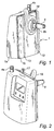
- Fig. 2 shows a display and set buttons.
Abstract
Description
- The present invention relates to a breathing-gas-saving device according to
claim 1. - Breathing gas is frequently supplied to a user in need from a gas cylinder or a gas generating apparatus which is connected to the user by a tube. The gas cylinder has an opening/shut-off valve, and a pressure reducer ensures that the pressure of the gas cylinder is reduced to a level suitable for inhalation. The gas is usually oxygen but other gases or gas mixtures can be used.
- DE-296 22 321.2 discloses such a device for dosed supply of gas to a user, said device saving gas by supplying gas during inhalation only, and letting the user's need for inhalation control the supplied amount of gas. To this end, the device comprises a sensor and associated electronics, the sensor detecting the negative pressure in inhalation and controlling a solenoid valve for opening, and the electronics ensuring that the duration of the opening state of the valve is controlled by the breathing frequency, the electronics possibly also determining the amount of gas supplied. The gas cylinder and the solenoid valve are interconnected by means of a long tube. The gas cylinder stores breathing gas at high pressure.
- A drawback of such a device resides in the large volume of gas that is accumulated in the tube, which large volume is a gas buffer. A further drawback is that different outlet pressures from the gas cylinder (from the pressure-reducer of the gas cylinder) produce different pressure losses in the tube during inhalation, which in turn results in the need of exchanging the control electronics or reprogramming thereof, so that the patient receives the correct breathing volume at correct time intervals during inhalation.
- The object of the invention is to eliminate or at least reduce the above drawbacks in a device of the type described above with dosed supply of breathing gas.
- A further object is to provide a practically manageable gas-saving device for breathing gas or treatment gas.
- The object is achieved by a gas-saving device having the features as stated in
claim 1, advantageous embodiments having the features stated in the dependent claims. - In other words, there is provided according to the invention a gas-saving, inhalation-controlled device with an integrated gas volume with a small pressure drop.
- An embodiment of the invention will now be described in more detail with reference to the accompanying illustrations, in which
- Fig. 1 is a view from the connection side of a device according to the invention;
- Fig. 2 is a view from the opposite side;
- Fig. 3 is an exploded view of the device;
- Fig. 4 is a front view of the schematically illustrated outlet of a prior-art pressure regulator for breathing gas bottles;
- Fig. 5 is an arrangement of the device; and
- Fig. 6 is a cross-sectional view of a pressure reducer in the arrangement according to Fig. 5.
-
- The device according to the invention comprises a
casing 1, which consists of two trough-shaped parts sensor 2, electronics (integrated printed circuit board) 3, asolenoid valve 4 with anoutlet 4a and power supply in the form of arechargeable battery 5. Thecasing part 1b and a partition wall 6 of the casing define between them agas chamber 7 which communicates with the outside of thecasing 1 by means of a quick connectingpiece 8. This is arranged for direct quick connection to the low pressure outlet of a pressure reducer or regulator of a gas cylinder (not shown), mounted on the gas cylinder. Thesolenoid valve 4 is mounted on the partition wall 6, on its side facing away from thechamber 7, so that its inlet (not shown) communicates with thechamber 7. Theoutlet 4a of thesolenoid valve 4 in the form of a connecting piece is arranged to be connected to one end of a tube, whose other user end has a nose halter to be connected to the user's nose. Thesolenoid valve 4 is arranged to open, i.e. make thechamber 7 communicate with the patient, through saidoutlet 4a and said tube, during the patient's inhalation, in the same way as in the above-described prior-art device. Theelectronics 3 and thesensor 2 are mounted in the space between the partition wall 6 and thecasing part 1a, and the electronics can be designed in the same way as in the above-described prior-art device. - The quick connecting
piece 8 has athread 8a on its rear part which opens into thegas chamber 7, and is fastened to thecasing part 1b by means of a nut (not shown). On the outside of thecasing 1 there is adisengaging unit 10 which is adapted to disengage the quick connectingpiece 8 and thus the device with itscasing 1 from the low pressure outlet of the pressure reducer of the gas cylinder. - The pressure regulator in the embodiment shown is of a type that is mounted on a valve unit marketed by GCE Gas Control Equipment AB and designated Combilite®, which has a shut-off valve, a manometer, a gas supply port and is screwable onto a gas cylinder. The pressure regulator is schematically shown in a front view in Fig. 4. Such a pressure regulator has in its low pressure outlet spring-
biased tongues 11 which project radially in the outlet duct and are movable apart, against spring action, by turning aring 12 at said outlet, but also radially outwards from the position shown, as indicated by arrows A and B. - The quick connecting
piece 8 has agroove 8b for engagement with thetongues 11 by snap action. In this engaging position, the device (i.e. the entire casing 1) is held on the gas cylinder, and to ensure immobility of the device on the gas cylinder there may be supplementary holding means, here in the form ofgrooves 13 on thecasing 1 for engagement with flanges on a normal valve-protecting cap on the gas cylinder. - The disengaging
unit 10 comprises afriction ring 14 of, for example, rubber material, and atorsion spring 15 which is fixed to a disengagingarm 16 at one end and to thecasing 1 at the other end and is arranged so that turning of the disengagingarm 16 for disengagement occurs against the action of the restoringspring 15, which in turn results in thearm 16, after disengagement, being automatically returned to its unloaded position. Thefriction ring 14 is arranged in a groove in thearm 16 and adapted to frictionally engage the outer surface of theturnable ring 12 of the pressure reducer. - The casing parts are releasably assembled by means of screws and, of course, suitable seals.
- The
gas chamber 7 has a volume suited for correct inhalation-controlled gas supply, i.e. a volume which allows a correct, suitable predetermined volume of gas to be quickly pressed into the lungs and which allows quick accumulation of the correct gas volume originating from the gas cylinder, at the correct pressure in thegas chamber 7. It has been found that, by being close to the gas cylinder and thesolenoid valve 4, agas chamber 7 with a volume of 35 cm3 can replace a conventionally used 4.5 m tube with a volume of 50 cm3, thereby saving space and eliminating the risk of entangling the tube. - In some situations, it may still be preferred to connect the gas cylinder to the
solenoid valve 4 by means of a tube. In the described device, the quick connectingpiece 8 and the disengaging unit are dismounted from thecasing 1, and the hole left in thecasing part 1b for the quick coupling 8 (intended for the gas) is stopped up by a plug, and thegas chamber 7 is connected to the pressure reducer by means of a tube which thanks to the existence and use of thegas chamber 7 in the above-describedcasing 1 can be short, so that the device - with the quick connecting piece and the disengaging unit removed - can be carried in the user's pocket or be attached to a pocket or a belt by means of a clip fixed to thecasing 1. To this end, thecasing 1 can be provided with a tube-connectible inlet 17 which communicates with thegas chamber 7 and is stopped up when thecasing 1 is connected directly, as described above, to the outlet of the pressure reducer. If the pressure reducer is of the type described above with an outlet to be connected to a quick coupling of the type as described above, theinlet 17 should of course be connected to the pressure reducer by means of a tube whose other end is connected to the quick coupling (of the type 8). - It will be appreciated that the device according to the invention is adjustable to different types of pressure regulators, which are available on the market with different permanent (set at the factory) output pressures or variable output pressures. They can be integrated units, like in the above-described Combilite® - with a shut-off valve (for the gas cylinder), a pressure regulator and a cylinder filling valve integrated in a body or separately connectible to a shut-off valve. Variants allowing the flow to be regulated are also available on the market. The device according to the invention can, of course, be modified for connecting its
chamber 7 to all these different types of valves/regulators. - An arrangement is illustrated in Fig. 5, which serves to allow use of the inventive device together with different pressure regulators with different output pressures, where the output pressure is higher than a predetermined pressure value, at which the device according to the invention operates. The arrangement comprises an additional pressure reducer or adaptor 20 (Fig. 6) which is adapted to supply the constant predetermined pressure value to the
chamber 7, independently of the input pressure from theordinary pressure regulator 21. Such pressure reducers (of the type described above as additional pressure reducer) are also known to those skilled in the art. The gas cylinder is designated 22. - It will be appreciated that the disengaging
unit 10 need not be designed as shown and described above, but also other types of disengaging arrangements are possible, according to the design of the outlet of the pressure regulator/reducer, not all of them having precisely the above-described tongue arrangement for quick coupling (intended for quick coupling to a tube). - Fig. 2 shows a display and set buttons.
Claims (5)
- A gas-saving inhalation-controlled device which has a breathing gas volume for inhalation originating from a pressurised gas cylinder or a gas generating apparatus with pressure-reducing means (20, 21), said breathing gas volume being supplied for inhalation through a solenoid valve (4) controlled by electronics, characterised in that the breathing gas volume is defined essentially by the boundary wall of a chamber (7) in a casing (1) which holds the solenoid valve (4) and the control electronics and which is connectible to the outlet of the pressure-reducing means directly by means of a short connecting piece (8) arranged on the casing, or by means of a short tube, where the short tube does not have a significant volume related to the breathing volume.
- A device as claimed in claim 1, characterised in that it comprises a pressure reducer (20) adapted to supply a predetermined constant breathing gas pressure to the chamber (7), said pressure reducer being arranged to be connected to the pressure-reducing means of the gas cylinder.
- A device as claimed in claim 1, characterised in that the connecting piece (8) is a quick coupling (8).
- A device as claimed in claim 3, characterised in that the quick coupling (8) is a snap-in fastener for cooperation with spring-biased tongues (11) of the outlet of the pressure reducer.
- A device as claimed in claim 3 or 4, characterised in that a spring-biased disengaging unit (11) for the quick coupling (8) is mounted on the casing (1), when the quick coupling engages said outlet.
Applications Claiming Priority (2)
| Application Number | Priority Date | Filing Date | Title |
|---|---|---|---|
| SE0302406A SE525769C2 (en) | 2003-09-10 | 2003-09-10 | Breath gas saver |
| SE0302406 | 2003-09-10 |
Publications (1)
| Publication Number | Publication Date |
|---|---|
| EP1516642A1 true EP1516642A1 (en) | 2005-03-23 |
Family
ID=28787292
Family Applications (1)
| Application Number | Title | Priority Date | Filing Date |
|---|---|---|---|
| EP04445092A Withdrawn EP1516642A1 (en) | 2003-09-10 | 2004-09-10 | Gas saver for breathing gas |
Country Status (2)
| Country | Link |
|---|---|
| EP (1) | EP1516642A1 (en) |
| SE (1) | SE525769C2 (en) |
Cited By (1)
| Publication number | Priority date | Publication date | Assignee | Title |
|---|---|---|---|---|
| CN105056359A (en) * | 2015-09-21 | 2015-11-18 | 青岛亿人亿宝物联网络信息技术有限公司 | Respiratory inductive intelligent oxygen supply device |
Citations (4)
| Publication number | Priority date | Publication date | Assignee | Title |
|---|---|---|---|---|
| US5099837A (en) * | 1990-09-28 | 1992-03-31 | Russel Sr Larry L | Inhalation-based control of medical gas |
| US6427690B1 (en) * | 1998-10-21 | 2002-08-06 | Airsep Corporation | Combined oxygen regulator and conservation device |
| EP1243822A1 (en) * | 2001-03-22 | 2002-09-25 | Gebr. Gloor AG | Quick connecting system |
| WO2002077511A1 (en) * | 2001-03-27 | 2002-10-03 | Invacare Corporation | Rapid connection coupling |
-
2003
- 2003-09-10 SE SE0302406A patent/SE525769C2/en not_active IP Right Cessation
-
2004
- 2004-09-10 EP EP04445092A patent/EP1516642A1/en not_active Withdrawn
Patent Citations (4)
| Publication number | Priority date | Publication date | Assignee | Title |
|---|---|---|---|---|
| US5099837A (en) * | 1990-09-28 | 1992-03-31 | Russel Sr Larry L | Inhalation-based control of medical gas |
| US6427690B1 (en) * | 1998-10-21 | 2002-08-06 | Airsep Corporation | Combined oxygen regulator and conservation device |
| EP1243822A1 (en) * | 2001-03-22 | 2002-09-25 | Gebr. Gloor AG | Quick connecting system |
| WO2002077511A1 (en) * | 2001-03-27 | 2002-10-03 | Invacare Corporation | Rapid connection coupling |
Cited By (1)
| Publication number | Priority date | Publication date | Assignee | Title |
|---|---|---|---|---|
| CN105056359A (en) * | 2015-09-21 | 2015-11-18 | 青岛亿人亿宝物联网络信息技术有限公司 | Respiratory inductive intelligent oxygen supply device |
Also Published As
| Publication number | Publication date |
|---|---|
| SE525769C2 (en) | 2005-04-19 |
| SE0302406D0 (en) | 2003-09-10 |
| SE0302406L (en) | 2005-03-11 |
Similar Documents
| Publication | Publication Date | Title |
|---|---|---|
| EP2040784B1 (en) | Mechanical ventilation system utilizing bias valve | |
| CA2495522C (en) | Regulated gas supply system | |
| US5881725A (en) | Pneumatic oxygen conserver | |
| EP2656868A3 (en) | Breathing assistance apparatus | |
| EP1927374A3 (en) | Apparatus for equalising pressure in an air respiratory system | |
| SE0402120L (en) | Gas regulator | |
| HK1090112A1 (en) | Proportional pressure regulator having positive and negative pressure delivery capability | |
| WO1999004841A8 (en) | Control device for supplying supplemental respiratory oxygen | |
| WO2000023134A1 (en) | Combined oxygen regulator and conservation device | |
| GB0802028D0 (en) | Powder inhaler flow regulator | |
| GB0204328D0 (en) | Flow indicator | |
| NZ591168A (en) | Controlling Pressure in CPAP Systems | |
| AU2031601A (en) | A valve device for controlled supply of a pressure fluid | |
| US20100108068A1 (en) | Hybrid electro-pneumatic conserver for oxygen conserving regulator | |
| EP1377768A4 (en) | Control valve monitoring | |
| EP1516642A1 (en) | Gas saver for breathing gas | |
| AU2005299806B2 (en) | Regulated gas supply system | |
| DE10346208A1 (en) | Pressure regulator for gas flow has chamber with built in proportional valve used to change flow orifice | |
| NZ520336A (en) | Leakproof gas pressure regulator | |
| AU2005205828A1 (en) | Compensating venturi vacuum system | |
| CA2517174A1 (en) | Compensating venturi vacuum system | |
| NO20051732L (en) | Gas valve with proportional output |
Legal Events
| Date | Code | Title | Description |
|---|---|---|---|
| PUAI | Public reference made under article 153(3) epc to a published international application that has entered the european phase |
Free format text: ORIGINAL CODE: 0009012 |
|
| PUAF | Information related to the publication of a search report (a3 document) modified or deleted |
Free format text: ORIGINAL CODE: 0009199SEPU |
|
| AK | Designated contracting states |
Kind code of ref document: A1 Designated state(s): AT BE BG CH CY CZ DE DK EE ES FI FR GB GR HU IE IT LI LU MC NL PL PT RO SE SI SK TR |
|
| AX | Request for extension of the european patent |
Extension state: AL HR LT LV MK |
|
| D17D | Deferred search report published (deleted) | ||
| 17P | Request for examination filed |
Effective date: 20050921 |
|
| 17Q | First examination report despatched |
Effective date: 20100521 |
|
| STAA | Information on the status of an ep patent application or granted ep patent |
Free format text: STATUS: THE APPLICATION IS DEEMED TO BE WITHDRAWN |
|
| 18D | Application deemed to be withdrawn |
Effective date: 20101201 |