EP1517281A2 - Safety nets for alerting of hazardous situations in air traffic - Google Patents
Safety nets for alerting of hazardous situations in air traffic Download PDFInfo
- Publication number
- EP1517281A2 EP1517281A2 EP03028757A EP03028757A EP1517281A2 EP 1517281 A2 EP1517281 A2 EP 1517281A2 EP 03028757 A EP03028757 A EP 03028757A EP 03028757 A EP03028757 A EP 03028757A EP 1517281 A2 EP1517281 A2 EP 1517281A2
- Authority
- EP
- European Patent Office
- Prior art keywords
- conflict
- prediction
- region
- aircraft
- predicted
- Prior art date
- Legal status (The legal status is an assumption and is not a legal conclusion. Google has not performed a legal analysis and makes no representation as to the accuracy of the status listed.)
- Granted
Links
- 231100001261 hazardous Toxicity 0.000 title claims abstract description 12
- 238000000034 method Methods 0.000 claims abstract description 81
- 238000000926 separation method Methods 0.000 claims description 95
- 239000000523 sample Substances 0.000 claims description 55
- 239000013598 vector Substances 0.000 claims description 53
- 230000035515 penetration Effects 0.000 claims description 31
- 238000012790 confirmation Methods 0.000 claims description 27
- 238000001914 filtration Methods 0.000 claims description 23
- 230000007774 longterm Effects 0.000 claims description 18
- 230000009194 climbing Effects 0.000 claims description 11
- 238000004891 communication Methods 0.000 claims description 11
- 230000008569 process Effects 0.000 claims description 11
- 238000013213 extrapolation Methods 0.000 claims description 10
- 230000000694 effects Effects 0.000 claims description 9
- 238000012545 processing Methods 0.000 claims description 9
- 230000007717 exclusion Effects 0.000 claims description 5
- 238000013480 data collection Methods 0.000 claims description 4
- 230000003068 static effect Effects 0.000 claims description 4
- 238000001514 detection method Methods 0.000 claims description 3
- 238000004422 calculation algorithm Methods 0.000 description 21
- 238000004458 analytical method Methods 0.000 description 12
- 238000012360 testing method Methods 0.000 description 11
- 238000010586 diagram Methods 0.000 description 7
- 238000005315 distribution function Methods 0.000 description 6
- 238000013461 design Methods 0.000 description 4
- 238000012417 linear regression Methods 0.000 description 4
- 230000001133 acceleration Effects 0.000 description 3
- 238000013459 approach Methods 0.000 description 3
- 230000008901 benefit Effects 0.000 description 3
- 238000012885 constant function Methods 0.000 description 3
- 230000007423 decrease Effects 0.000 description 3
- 230000007246 mechanism Effects 0.000 description 3
- 238000005457 optimization Methods 0.000 description 3
- 238000007619 statistical method Methods 0.000 description 3
- 230000002730 additional effect Effects 0.000 description 2
- 238000012512 characterization method Methods 0.000 description 2
- 230000003247 decreasing effect Effects 0.000 description 2
- 230000008030 elimination Effects 0.000 description 2
- 238000003379 elimination reaction Methods 0.000 description 2
- PXFBZOLANLWPMH-UHFFFAOYSA-N 16-Epiaffinine Natural products C1C(C2=CC=CC=C2N2)=C2C(=O)CC2C(=CC)CN(C)C1C2CO PXFBZOLANLWPMH-UHFFFAOYSA-N 0.000 description 1
- 229920006068 Minlon® Polymers 0.000 description 1
- 230000006978 adaptation Effects 0.000 description 1
- 238000004364 calculation method Methods 0.000 description 1
- 230000008859 change Effects 0.000 description 1
- 125000004122 cyclic group Chemical group 0.000 description 1
- 230000007812 deficiency Effects 0.000 description 1
- 230000001934 delay Effects 0.000 description 1
- 230000001419 dependent effect Effects 0.000 description 1
- 230000006872 improvement Effects 0.000 description 1
- 238000003780 insertion Methods 0.000 description 1
- 230000037431 insertion Effects 0.000 description 1
- 239000011159 matrix material Substances 0.000 description 1
- 238000000638 solvent extraction Methods 0.000 description 1
- 230000036962 time dependent Effects 0.000 description 1
- 230000001052 transient effect Effects 0.000 description 1
- 230000001960 triggered effect Effects 0.000 description 1
- 238000010200 validation analysis Methods 0.000 description 1
Images


Classifications
-
- G—PHYSICS
- G08—SIGNALLING
- G08G—TRAFFIC CONTROL SYSTEMS
- G08G5/00—Traffic control systems for aircraft, e.g. air-traffic control [ATC]
- G08G5/04—Anti-collision systems
- G08G5/045—Navigation or guidance aids, e.g. determination of anti-collision manoeuvers
-
- G—PHYSICS
- G08—SIGNALLING
- G08G—TRAFFIC CONTROL SYSTEMS
- G08G5/00—Traffic control systems for aircraft, e.g. air-traffic control [ATC]
- G08G5/0073—Surveillance aids
- G08G5/0078—Surveillance aids for monitoring traffic from the aircraft
-
- G—PHYSICS
- G08—SIGNALLING
- G08G—TRAFFIC CONTROL SYSTEMS
- G08G5/00—Traffic control systems for aircraft, e.g. air-traffic control [ATC]
- G08G5/0073—Surveillance aids
- G08G5/0086—Surveillance aids for monitoring terrain
Definitions
- the present invention relates to a system and a method for alerting of potentially hazardous situations in air traffic on the basis of surveillance data wherein predicted conflicts are identified based on the prediction of future air traffic situations.
- Safety net are automated tools intended to alert controllers of potentially hazardous situations predicted in the near future. They are based on trajectories predicted from surveillance data.
- a safety net is transparent to the controller. Whenever the system detects a potential danger in the near future, it displays an alert message. The controller can then identify an appropriate avoiding manoeuvre and communicate the instructions to the pilot(s) concerned. This means that the radar controller should not adopt a passive attitude by blindly relying on the safety net function and waiting until an alert is indicated to him;
- a conflict is a violation of defined safety criteria involving one or more aircraft.
- a real conflict is a conflict that actually occurs. Such a conflict is a critical situation which may have dramatic consequences and should always be avoided.
- a predicted conflict is a conflict that is likely to occur in the near future. Such a conflict is based on a prediction of air traffic situation in the near future.
- Safety net functions and safety net systems according to the present invention identify both real and predicted conflicts, whereas the latter may be seen as a generalization of the former.
- the identification of a real conflict is a deterministic process, i.e., the decision of whether or not one or more aircraft are in real conflict is simply determined by the actual track data of the aircraft
- the identification of a predicted conflict is not a deterministic process.
- the reason for this lies in the non-deterministic nature of future air traffic situation prediction in which errors are unavoidable. This is because aircraft may perform unexpected manoeuvres or change the speed in the prediction time frame etc. The farther in the future a prediction is made, the greater the prediction error.
- the warning time of a conflict alert is defined as the time interval between the first communication of an alert and the start of the predicted violation of the safety criteria.
- the warning time should be sufficiently large to cover the time needed by the radar controller to formulate an appropriate avoiding manoeuvre and communicate it to the pilot(s), plus the time need by the latter to perform a manoeuvre and eliminate the potential danger.
- unpredictable late manoeuvres might severely restrict the warning time by generating a predicted conflict in very short term.
- a basic idea of the present invention consists of defining a stochastic model for trajectory prediction in which the uncertainty of the prediction is represented as a function of the prediction time.
- the stochastic model(s) for predicting trajectories is preferably used to construct a stochastic model for conflict prediction.
- probabilities of conflict are compared to minimum confidence levels and allow to decide whether a given predicted situation is a predicted conflict or not.
- the minimum confidence level required to predict a conflict is defined as a function of the urgency of the conflict, expressed by its prediction time. This function is independent of the uncertainty of trajectory prediction.
- the present invention provides a safety net method or method for alerting of potentially hazardous situations in air traffic on the basis of surveillance data wherein predicted conflicts are identified based on the prediction of future air traffic situations by definition of a stochastic model for trajectory prediction in which the uncertainty of the prediction is preferably based on a variable aircraft 3D speed vector and is represented as a function of the prediction time. Further, preferably at least one stochastic model of predicted trajectories is used for constructing a stochastic model for conflict prediction in this method.
- the probabilities of conflict are compared to minimum confidence levels, wherein a decision is made whether a predicted situation is a predicted conflict or not based upon this comparison to minimum confidence levels.
- the method preferably defines a minimum confidence level for predicting a conflict as a function of the urgency of the conflict, expressed by its prediction time. Further, a time interval between a first communication, e.g. by displaying etc., of an alert and the start of the predicted violation of the safety criteria is preferably sufficiently large to cover the time needed by a radar controller to formulate an appropriate avoiding manoeuvre and communicate it to the pilot(s) plus the time needed by the latter to perform the manoeuvre and eliminate the potential danger.
- each air space region is classified to belong to a region type.
- each region type has a different set of trajectory prediction and conflict prediction parameters and hence different stochastic models for trajectory and conflict prediction.
- manoeuvre region types has been introduced in addition to the standard region types. Regions of these types are centred at points in the vicinity of which aircraft are expected to perform a manoeuvre. These points preferably correspond to VORDME (Very High Frequency Omnidirectional Radio Range Distance Measuring Equipment) and NDB (Non Directional Beacon) way points. Such manoeuvre regions are aimed at predicting aircraft manoeuvres.
- VORDME Very High Frequency Omnidirectional Radio Range Distance Measuring Equipment
- NDB Non Directional Beacon
- a different set of trajectory parameters is used and the uncertainty of the trajectory prediction is adapted according to the respective region types and the properties (e.g. position) of the respective aircraft(s).
- the method steps are repeated in cycles wherein a confirmation window records the conflicts of the last cycles and wherein, at the end of one cycle, the confirmation windows are updated with the conflicts predicted during this cycle. Further, a conflict is confirmed and communicated if the conflict was predicted at least c times in the last cycles and wherein the parameter c depends on the prediction time frame and the region type of the aircraft involved in the conflict.
- the method is suitable for all main safety nets such as, i.a., Short Term Conflict Alert (STCA), Minimum Safe Altitude Warning (MSAW) and/or Area Proximity Warning (APW) wherein the method may be adapted in order to fulfil special requirements of one or more safety nets.
- STCA Short Term Conflict Alert
- MSAW Minimum Safe Altitude Warning
- APIW Area Proximity Warning
- the method is preferably suitable for predicting violations of defined separation criteria between at least two aircraft, for predicting minimum safe altitude violations of at least one aircraft, and/or for predicting penetrations of protected airspaces by at least one aircraft as well as for predicting other violations of safety criteria in air traffic.
- the present invention provides a safety net system or system for alerting of potentially hazardous situations in air traffic comprising a surveillance data detection and processing means wherein predicted conflicts are identified based on the prediction of future air traffic situations by a stochastic control means which defines a stochastic model for trajectory prediction in which the uncertainty of the prediction is represented as a function of the prediction time. Further, preferably at least one stochastic processing and control means for predicted trajectories constructs a stochastic model for conflict prediction. The conflict is further preferably communicated by a conflict communication means.
- the system according to the present invention for alerting of potentially hazardous situations in air traffic preferably comprises: structures or data structures, such as an input track, which contains all input track information relevant to the safety net; a trajectory, i.e., a 3D trajectory for one aircraft; a predicted track, which is an extrapolation of an input track; and/or a conflict, which is the safety net output containing all relevant conflict information as well as statistical data which are all data useful for a statistical analysis of the system.
- the system further comprises the data structure region type, which is a set of safety net parameters that depend on the region type.
- the system further preferably comprises the following main modules: input track filtering, which eliminates input tracks which do not satisfy certain selection criteria; trajectory prediction, which generates predicted trajectories from input tracks; trajectory probing, which discretizes the prediction time frame into a finite number of time points and generates a predicted track on a given trajectory for each such time point; a conflict prediction, which performs conflict prediction on predicted tracks and which is specific to each individual safety net; a conflict confirmation which confirms conflicts over several input track updates and/or online statistical data collection, which collects online statistics and analyses the performance of the safety net systems.
- the system further comprises the main module region type identification, which identifies the region type of an input track by determining the air space region containing the track.
- the input of a safety net function is essentially based on radar data and does not require continuous inputs from the radar controller for its proper functioning.
- the system preferably also makes use of aircraft intention information, e.g. cleared flight levels, provided by a flight plan or controller input etc.
- the safety net i.e. the method and system according to the present invention, preferably consider different air space regions, representing volumes of air space.
- Each air space region has a region type.
- Each region type is defined by or is represented by a different set of trajectory prediction and conflict prediction/confirmation parameters.
- manoeuvre region types are preferably introduced.
- regions of these types are centered at points in the vicinity of which aircraft are expected to perform a manoeuvre. These points preferably correspond to VORDME (Very High Frequency Omnidirectional Radio Range Distance Measuring Equipment) and NDB (Non Directional Beacon) way points.
- VORDME Very High Frequency Omnidirectional Radio Range Distance Measuring Equipment
- NDB Non Directional Beacon
- region types preferably are divided into the two classes, standard region types and manoeuvre region types.
- standard region types are "Upper En-Route Control Areas” (upper CTA), “Lower En-Route Control Areas” (lower CTA) or “Outer Terminal Air Spaces”, “Terminal Manoeuvre Areas” (TMA), “Control Zones” (CTA) and/or “Stacks” (holding areas).
- Standard region types are preferably defined by a unique region type identifier, a set of trajectory prediction parameters and/or a set of conflict prediction/confirmation parameters.
- Manoeuvre region types are preferably defined by a unique region type identifier, a set of trajectory prediction parameters and/or a reference to a standard region type, called base type.
- the manoeuvre region type inherits the conflict prediction/confirmation parameters from its base type.
- Each air space region is preferably defined by the attributes: "unique region identifier”, “unique region type identifier”, “lateral geometry of the region”, “height band of the region”, “region priority”, “activity flag” and/or “exclusion flag”.
- a region has preferably one of the following lateral geometries.
- a region can have the lateral geometry of a simple closed polygon, defined as a list of vertices. It is noted that standard geometrical algorithms are preferably used to determine whether a point lies in a simple closed polygon.
- a region may further have a lateral geometry of a distance radius circle, defined by a centre and a distance radius.
- a region can have the geometry of a time radius circle, defined by a centre and a time radius. An aircraft is considered to belong to a time radius circle if the condition distance to centre ⁇ aircraft lateral speed * time radius is fulfilled.
- Manoeuvre regions are preferably represented by time radius circles and the time radius of the circle is preferably close or proportional to the maximum prediction time.
- the lower or upper heights of a region are preferably specified as altitudes and/or as flight levels.
- regions can be included in or overlap other regions. Hence, an aircraft can fall within more than one defined region. In this case, the region with the highest priority is selected.
- the activity flag of a region determines whether the region is active, i.e., if it has to be considered by the safety net.
- the exclusion flag specifies whether the safety net function is inhibited in the region.
- the activity and exclusion flags may preferably be changed dynamically.
- regions may preferably be defined dynamically.
- the safety net For receiving input, as discussed above, the safety net comprises a safety net interface.
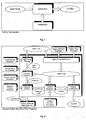
- Such interface of any safety net function preferably comprises the following data structures, as is shown in Fig. 1.
- the input track data structure comprises all input track information relevant to the safety net.
- a conflict data structure is a safety net output containing all relevant conflict information and the parameters are configuration parameters of the safety net system.
- the input track comprises data such as: track identification; mode 3/A code; call sign, if available from flight plan data; lateral position; mode C; sea level mode C or aircraft altitude; lateral speed vector; lateral manoeuvre indication, with direction and rate of turn; vertical manoeuvre indication, with direction and rate of climb/decent; current time; cleared (assigned) flight level, if available; and/or Reduced Vertical Separation Minimum (RVSM) compliance flag, if available from flight plan data.
- data such as: track identification; mode 3/A code; call sign, if available from flight plan data; lateral position; mode C; sea level mode C or aircraft altitude; lateral speed vector; lateral manoeuvre indication, with direction and rate of turn; vertical manoeuvre indication, with direction and rate of climb/decent; current time; cleared (assigned) flight level, if available; and/or Reduced Vertical Separation Minimum (RVSM) compliance flag, if available from flight plan data.
- RVSM Reduced Vertical Separation Minimum
- sea level mode C or aircraft altitude are preferably suitable for air space regions whose lower or upper height bands are defined as an altitude.
- aircraft altitude aircraft mode C
- the sea level mode C can be obtained from a QNH pressure value, assumed to be available from elsewhere in the system.
- the method and system e.g. suitable for the STCA, MSAW, APW etc. preferably comprises the following data structures: an input track, which contains all input track information relevant to the safety net; a trajectory, i.e., a 3D trajectory for one aircraft; a predicted track which is preferably the extrapolation of an input track; a conflict, which is the safety net output containing all relevant conflict information; the region type, which is a set of safety net parameters that depend on the region type; and/or statistical data, which are all data useful for statistical analysis of the system.
- a safety net function is preferably composed of one or more of the following main modules: a region type identification, which identifies the region type of an input track by determining the air space region containing the track; an input track filtering, which eliminates input tracks which do not satisfy certain selection criteria; a trajectory prediction, which generates predicted trajectories from input tracks; a trajectory probing, which discretizes a prediction time frame into a finite number of time points and generates a predict track on a given trajectory for each such time point; a conflict prediction, which performs conflict prediction on predicted tracks and which is preferably specific to each individual safety net; a conflict confirmation, which confirms conflicts over several input track up dates; and/or an on-line statistical data collection which collects online statistics and analyses the performance of the safety net system.
- a region type identification which identifies the region type of an input track by determining the air space region containing the track
- an input track filtering which eliminates input tracks which do not satisfy certain selection criteria
- a trajectory prediction which generates predicted traject
- the configuration parameters of the safety net preferably comprise: general safety net parameters; communication parameters; input track filtering parameters; trajectory probing parameters; conflict prediction parameters; region definition parameters; and/or region type parameters.
- the region type parameters preferably comprise all safety net parameters whose values depend on the region type. These parameters comprise: trajectory prediction parameters; conflict prediction parameters; and/or conflict confirmation parameters.
- one or more of the input track filtering and/or conflict prediction parameters depend on the safety net concerned. The remaining parameters are common to all safety nets and are specified later in the description.
- Fig. 2 shows the generic data flow diagram representing the main modules of preferred safety net functions and the corresponding data links as well as the configuration parameters of the safety net.
- the input track filtering module receives input track data containing all input track information relevant to the safety net and eliminates input tracks which do not satisfy certain selection criteria based on input track filtering parameters, then passing all relevant track information to the trajectory prediction module.
- the region type identification module identifies the region type of an input track by determining the air space region containing the track based on the input track data and thus, identifies the region type data, i.e. the set of safety net parameters that depend on the region type.
- the region type identification module and identification process is further based on region definition parameters and region type parameters, wherein the region type parameters contain all safety net parameters whose values depend on the region type, as discussed above.
- the trajectory prediction module generates predicted trajectories from input tracks such as the output of the input track filtering module and the region type identification module, i.e. input track data and region type data.
- the predicted trajectories of the trajectory prediction module i.e. the trajectory data, which is the 3D trajectory for one aircraft, is communicated to the trajectory probing module which discretizes the prediction time frame into a finite number of time points and generates a predicted track on a given trajectory for each such time point, i.a. based on trajectory probing parameters.
- the predicted track generated by the trajectory probing module is received by the conflict prediction module which further receives region type data and conflict prediction parameters and then performs conflict prediction on the predicted tracks.
- the conflict prediction module and the conflict prediction are specific to each individual safety net.
- the output of the conflict prediction module i.e. the conflict data are confirmed by the conflict confirmation module over several input track updates and preferably the region type data.
- the output of the conflict confirmation module is the conflict data as the safety net output containing all relevant
- the on-line statistical data collection module collects on-line statistics and analyses the performance of the safety net system. Further parameters received by the safety net are, e.g. general safety net parameters and/or communication parameters.
- the safety net function reads a preferably continuous stream of input tracks, received from e.g. the radar tracking system, for example by means of a UDP (User Datagram Protocol) communication medium.
- the safety net may be considered as a cyclic algorithm that performs conflict prediction on a set of input tracks whose time stamps differ by less then TAU, where TAU denotes the cycle time of the safety net.
- TAU is approximately 4 to 6 seconds.
- the algorithm starts by checking if the system is still in the current cycle, i.e. it tests for the condition
- the type of air space region containing T is identified.
- the input track filter checks whether T is a valid track. If not, the algorithm drops T and waits for the next track. Otherwise, the trajectory predictor generates a trajectory TR from T.
- the trajectory probing module then produces a set of predicted tracks ST on the predicted trajectory TR.
- the conflict prediction module subsequently generates conflicts involving the predicted tracks in ST and inserts these conflicts in the set SC of conflicts of the current cycle. It also stores the set ST in its internal data structures. Finally, statistical data is collected.
- SC is set to the empty set and t can be set to any valid time value.
- the cycle time TAU is preferably determined by minimizing the time before confirming and hence communicating a conflict, under the constraint that all pairs of tracks are considered within one cycle. Therefore, TAU is equal to the time between two successive updates of a given track.
- Fig. 3 represents the generic safety net state diagram of safety net functions as discussed above.
- the input track filter eliminates all input tracks which do not satisfy certain selection criteria, as already indicated above.
- an input track is eliminated if any of the conditions "it is in no defined region” and/or "it is in an exclusion region” apply.
- height information is preferably obtained by extrapolation of the last mode C readout.
- the extrapolated height is considered invalid and the input track is eliminated if its last mode C readout was more than a certain time MAX_T_LAST_ MODEC ago.
- trajectory prediction is an approximation process which inevitably leads to positional errors.
- a stochastic model for trajectory prediction has been defined, in which the uncertainty of the prediction is represented as a function of the prediction time.
- Trajectory prediction comprises or can be decomposed into prediction in the lateral plane and prediction on the vertical axis. Preferably, these two predictions are performed separately.
- the mean trajectory in the lateral plane is preferably determined by means of a standard turn angle which preferably depends on the region type.
- the mean trajectory is preferably obtained by linear extrapolation of the current lateral speed vector.
- the mean trajectory on the vertical axis is preferably determined by linear extrapolation of the current vertical speed.
- an intended or assigned flight level is available, e.g. from controller input, flight plan data or some other source, and the aircraft is climbing or descending, the stochastic model is modified to take into account the clipping of the aircraft at the assigned flight level.
- the uncertainty of the prediction is modelled as a function of the prediction time and the aircraft speed, and preferably further depends on the region type concerned as well as on the aircraft attitude, i.e. whether the aircraft is manoeuvring or not.
- a trajectory is preferably composed of (1) a lateral trajectory in the space (t, x, y) and (2) a vertical trajectory in the space (t, z). Further, lateral and vertical trajectories are stochastic functions defined by (1) a mean, i.e. most likely, trajectory and (2) an error variance.
- the error variance models the uncertainty of the prediction.
- a preferred error variance will be described in detail below.
- e e (v, t) denotes the lateral (resp. vertical) positional error vector at prediction time t for a lateral (resp. vertical) speed v.
- the square root ⁇ of the error variance is called the standard error.
- where ⁇ is a constant and r is a normal random variable of mean 0, i.e., Er 0.
- the parameters a and b depend on the region type and/or the aircraft attitude, i.e., whether the aircraft is manoeuvring or not. Further below, a method for estimating these parameters from the analysis of the real track data will be discussed.
- the mean lateral trajectory is preferably obtained by linear extrapolation of the current lateral speed vector.
- the mean lateral trajectory is preferably obtained by generating a circular trajectory with a current lateral speed and turn rate of the aircraft until the predicted end of the manoeuvre, followed by a tangent straight line.
- a crucial or difficult task is the estimation of how long the aircraft will perform its manoeuvre.
- a standard angle of turn, TURNANGLE given as a region type parameter, is introduced.
- the distribution function of the lateral positional error vector e (e x , e y ) is a normal distribution with mean 0 which is independent of the direction of the vector e.
- Such assumption has the advantage of providing a stochastic model for the distance between the lateral positions of two aircraft which does not depend on the direction of the relative lateral position of the aircraft. This assumption also justifies the definition of the error variance ⁇ 2 , as given above.
- (1) i.e.
- Fig. 4 shows a mean lateral trajectory generated for a manoeuvring aircraft in the (x, y) plane. It is composed of a circular arc followed by a tangent straight line. The figure also represents the error variance ⁇ 2 as a function of the prediction time t.
- the mean vertical trajectory is preferably determined by linear extrapolation of the current vertical speed.
- the mean vertical trajectory and the error variance ⁇ 2 need to be modified to take into account the clipping of the aircraft at the assigned flight level.
- the uncertainty interval is thus "clipped" at the assigned level. It is noted that the 3 ⁇ value corresponds to a 99.74 % probability that the real position of the aircraft lies inside the interval [z min , Z max ].
- ⁇ * (z max - z min ) / 6.
- the prediction In case of a temporary loss of mode C information, the prediction must preferably be started at the time of the last mode C readout instead of the current time.
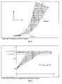
- Fig. 5 shows the mean vertical trajectory generated for a climbing aircraft with an assigned flight level in the (t, z) plane, which comprises three line segments.
- the newly introduced standard error ⁇ * is considered as well as the tolerance interval [z a - FL_TOL, z a + FL_TOL].
- trajectory probing consists of discretizing the prediction time frame into a finite number of equally spaced time points, called probes. For each probe, the probing process generates a static traffic picture ("a snapshot") represented by a set of predicted tracks.
- a snapshot a static traffic picture
- This probing approach has, i.a., the important advantages that it provides a clear separation between movement and conflict prediction, that it substantially reduces the complexity of the conflict prediction module which can work with static traffic pictures and does not have to deal with time-dependent 4D-trajectories, thus avoiding complex equations of movement, that it provides a simple stochastic model at each probing point and that it is very simple conceptually.
- a predicted track is defined by: a track identification; a probe; a position vector; and/or a speed vector (v x , v y , v z ).
- the position vector is a stochastic variable, preferably defined by: a mean position vector (x, y, z) and/or an error variance vector ( ⁇ xy 2 , ⁇ z 2 ).
- a probe p is in a short term prediction time frame if 0 ⁇ p ⁇ SHORT_TERM; a medium term prediction time frame if SHORT_TERM ⁇ p ⁇ MEDIUM_TERM; and a long term prediction time frame if MEDIUM_TERM ⁇ p ⁇ LONG_TERM.
- SHORT_TERM 30 seconds
- MEDIUM_TERM 60 seconds
- LONG_TERM 120 seconds.
- the probing process generates a number, NBPROBES, of preferably equally spaced probes in the interval [0, LONG_TERM]. For a given trajectory, the probing process determines, for each probe p, the following predicted track:
- the vector (x, y, z) is the position on the mean lateral trajectory at p and the height z is the position on the mean vertical trajectory at p.
- the norm of the vector (v x , v y ) is equal to the norm of the current lateral speed vector and its direction is parallel to the mean lateral trajectory at p.
- the rate vz is equal to the slope of the mean vertical trajectory at p.
- ⁇ xy 2 is the error variance of the lateral trajectory at ((v x 2 + v y 2 ) 1/2 , p) and ⁇ z 2 is the error variance of the vertical trajectory at (v z , p).
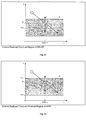
- Fig. 6 shows the lateral position in the (x, y) plane as well as speed (v x , v y ) and error variance ( ⁇ xy 2 ) of predicted tracks for probes 0 to 7.
- Fig. 7 shows the vertical position (z, t), speed (v z ) and error variance ( ⁇ z 2 ) of predicted tracks for probes 0 to 7.
- a number of probes NB_PROBES should be large enough to neglect the discretization error.
- making the number of probes too small deteriorates the system performance. Therefore, a good trade-off has to be found between discretization error and system performance.
- the at least one stochastic model of predicted track or stochastic models of predicted tracks are used to construct a stochastic model for conflict prediction.
- a probability of conflict is compared to a minimum confidence level and allows to decide whether a given predicted situation is a predicted conflict or not.
- p confl is the probability of a conflict and p min is a threshold probability value representing the minimum confidence level required to predict a conflict.
- p min is a threshold probability value representing the minimum confidence level required to predict a conflict.
- a conflict is predicted if and only if the relation p confl ⁇ p min holds.
- the minimum probability p min is defined as a function of the urgency of the conflict, expressed by its prediction time t.
- the function p min (t) is independent of the uncertainty of trajectory prediction. Following the discussion above, the function p min (t) should be increasing with the prediction time t, as can be seen in Fig. 8.
- the ability to specify, for each prediction time, the minimum confidence level required to predict a conflict enables an optimal trade-off between in-time conflict prediction and nuisance alert rate.
- the lower bound p min L (t) achieves the highest warning times but features also the highest nuisance alert rate.
- the upper bound p min U (t) achieves the lowest warning times but attains the lowest nuisance alert rate.
- the choice of the function p min (t) is preferably assisted by estimating both its warning time loss with respect to the function p min L (t) and its nuisance alert rate increase with respect to the function p min U (t). Further in the specification, a statistical method will be presented which determines these properties for each function p min (t) and enables a convenient optimization of this function.
- p min (t) is preferably defined as a piecewise constant function with three distinct values for short, medium and long term prediction time frames, as can be seen in Fig. 9:
- the stochastic model is compared with a deterministic model, which does not use any uncertainty information for trajectory prediction.
- a deterministic model can be obtained by setting the error variance of trajectory prediction to zero in the stochastic model as discussed above.
- the deterministic model is unable to estimate to what extent a predicted conflict may be trusted, because it does not use any uncertainty information for trajectory prediction.
- the deterministic model does not take into account the predicted penetration depth of the safety cylinder centered at each aircraft. Therefore, contrary to the stochastic model, it does not distinguish between marginal and clear predicted conflicts, depending on the uncertainty of the predicted position of an aircraft inside another aircraft's safety cylinder.
- systems based on such a deterministic model typically address this problem by introducing complex heuristics, which consider the region type, trajectory type, aircraft speed, penetration depth of the safety cylinder, etc.
- the validation and optimization of these heuristics are difficult tasks in general. As a consequence, an optimal trade-off between in-time conflict prediction and nuisance alert rate is not as easy to achieve as in the stochastic model.
- a conflict confirmation mechanism is introduced in order to take into account erroneous track data or transient track values.
- a confirmation window records the conflicts of the last WINSIZE cycles.
- the confirmation windows are updated with the conflicts predicted during this cycle. If a conflict was predicted at least c times in the last WINSIZE cycles, the conflict is confirmed and communicated, preferably displayed, to the user/controller.
- the parameter c depends on at least the prediction time frame, as described above, and/or the region type of the aircraft involved in the conflict.
- WINSIZE 5
- MIN_NBCONFL_SHORT 1
- MIN_NBCONFL_MEDIUM 2
- MIN_NBCONFL_LONG 3.
- a preferred method for determining optimal turn angles is given.
- a standard angle of turn TURNANGLE is used to predict lateral manoeuvre trajectories.
- a preferred method for determining an optimal standard turn angle for each region type is presented. The preferred method is based on the minimization of an objective error function and on observed manoeuvres from real track data.
- two manoeuvre trajectories are considered for an aircraft with radial acceleration a r .
- the optimal angle of turn ⁇ * is preferably approximated for each region type from real track data.
- the expectations are preferably approximated by the following formulae: where ⁇ i and a r,i , respectively, are the total turn angle and radial acceleration for manoeuvre i (0 ⁇ i ⁇ n) observed from real track data.
- Distinct values of the parameters a and b are preferably calculated in the lateral plane and on the vertical axis for each defined region type and aircraft attitude, i.e., whether the aircraft is manoeuvring or not.
- the calculation of error variance parameters is as follows. For each track update in the time frame [0, LONG_TERM] starting at update i, the positional error ⁇ e ⁇ 2 is computed by comparison with the predicted trajectory generated for update i. y; is now defined as the corresponding mean value of ⁇ e ⁇ 2 2 /dt 2 and x i is defined as the square speed v 2 of track update i.
- a linear regression between x and y with the set S of pairs (x i ,y i ) generated for track updates of aircraft within a given region type and within a given attitude is constructed for each region type and aircraft attitude (manoeuvring or not).
- n is defined as the number of elements in S.
- Tables 1 to 9 present preferred specification of the safety net parameters as well as approximate preferred values of the parameters which are preferably common to all safety nets.
- Table 1 shows general safety net parameters;
- Table 2 shows the specification of communication parameters;
- Table 3 shows the specification of input track filtering parameters;
- Table 4 shows the specification of trajectory probing parameters;
- Table 5 shows the specification of region definition parameters;
- Table 6-9 show region type parameters wherein Table 6 shows the specification of general region type parameters;
- Table 7 shows the specification of trajectory prediction parameters;
- Table 8 shows the specification of conflict prediction parameters;
- Table 9 shows the specification of conflict confirmation parameters.
- Example TYPEID Region Type Identification 0 CLASS Class of Region Type (standard, manoeuvre) Standard BASE_TYPEID Base type identification for manoeuvre region type 0 Specification of Trajectory Prediction Parameters Depending on Region Type Parameter Description
- warning time and nuisance alert rate will be analysed.
- the stochastic model preferably is parameterized by the minimum confidence level function p min (t). This function defines a certain trade-off between in-time conflict prediction and nuisance alert rate.
- the proposed method preferably serves as an assisting tool for the optimization of the function p min (t) and hence of the latter trade-off.
- the lower bound p min L(t) achieves the highest warning times but features also the lowest desirability values.
- the upper bound p min U (t) achieves the lowest warning times but attains the highest desirability values.
- the choice of the function p min (t) is preferably assisted by estimating both its warning time loss with respect to the function p min L (t) and its desirability loss with respect to the function p min U (t). Now the warning time and desirability losses will be formally defined.
- a set S of n conflicts is considered which have been generated both by the function p min (t) and a lower bound p min L (t).
- the warning time loss of p min (t) with respect to p min L (t) in set S is preferably defined as the square root of the mean square of the relative warning time differences:
- a set S of n conflicts is considered which have been generated by the function p min (t) but not by an upper bound p min U (t).
- d i be the alert desirability of conflict i in S.
- the desirability loss of p min (t) with respect to p min U (t) in set S is preferably defined as the square root of the mean square of the desirability values:
- a tolerance d tol on the desirability may be imposed and the relation e d ⁇ -d tol may be used as an acceptance test of the function p min (t).
- TMA Terminal Manoeuvre Area
- U Upper Airspace
- Warning Time and Desirability Losses for Different Functions p min (t) p min (t) Warning Time Loss e w in % Desirability Loss e d in sec No P_MIN_SHORT, P_MIN_MEDIUM, P_MIN_LONG TMA UA TMA UA 1 0.1,0.1,0.1 0 0 64 76 2 0.9,0.5,0.1 31 20 80 86 3 0.1,0.2,0.3 35 21 35 70 4 0.1,0.5,0.5 48 35 23 54 5 0.1,0.5,0.9 49 45 23 25 6 0.9, 0.9, 0.9 89 65 0 0 0
- Example 2 shows a decreasing function p min (t). It features a higher warning time loss and slightly higher desirability loss than example 1. Furthermore, example 2 has nearly the same warning time loss but a much higher desirability loss (especially for TMA) than example 3. Therefore, examples 1 and 3 are preferred to example 2. In general, decreasing functions p min (t) are preferably avoided, as already argued above. It can also be observed that the warning time and desirability losses are similar for TMA and UA in example 5, while they differ significantly in example 3. This can be explained by a higher uncertainty of trajectory prediction in TMA than in UA. Finally, it can be observed that examples 4 and 5 yield similar warning time and desirability losses for TMA but quite different losses for UA. Again, this is due to a higher uncertainty of trajectory prediction in TMA than in UA.
- STCA Short Term Conflict Alert
- a Short Term Conflict Alert (STCA) system is a safety net aimed at detecting traffic situations that might lead to a violation of defined separation criteria between at least two aircraft in a near future and warning the radar controller of this potential danger.
- STCA Short Term Conflict Alert
- a conflict in the context of the STCA safety net, will preferably correspond to a simultaneous infringement of defined lateral and vertical separation minima between two aircraft.
- a conflict is further characterized by (1) its nature, (2) its severity and/or (3) its uncertainty.
- conflict is expressed in terms of properties of the conflict.
- properties of the conflict include different types of separation infringements and geometrical properties such as the so called crossing and divergence properties of a pair of aircraft.
- the severity of a conflict depends on its nature and is preferably determined by combining the various properties of the conflict. In order to express the severity of a conflict, distinct conflict categories will be defined.
- the uncertainty of a conflict is based on the uncertainty of trajectory prediction, in which errors are unavoidable, as already discussed above. This uncertainty is represented by a stochastic model for minimum separation infringement.
- the conflict characterisation provides the radar controller with detailed information about a conflict situation, which enables him to analyse the situation more precisely and rapidly, before making a decision and possibly formulating an avoiding manoeuvre in order to eliminate the conflict.
- conflict characterisation further helps making more precise and detailed off-line analysis of conflict situations.
- the latter analysis may in turn be used, e.g., for tuning the STCA system.
- the generic conflict prediction module comprises two main modules, i.e., a conflict category prediction module and a coarse pair filtering module.
- the conflict category prediction module predicts the conflict category of predicted pairs, i.e., pairs of predicted tracks, and generates conflicts.
- the coarse pair filtering module generates predicted pairs by restricting the set of predicted tracks that need to be compared to a given predicted track in the conflict category prediction algorithm.
- conflict nature this is represented by a set of properties of the conflict.
- the latter preferably include properties of the geometrical situation of the conflict, such as the crossing and divergence properties of a pair of aircraft and/or different types of separation infringements, expressing the severity of separation loss.
- the crossing and divergence tests are applied to a pair of aircraft.
- the crossing and divergence properties represent some safety conditions about the local geometry of a conflict situation. These properties are based on current or predicted track positions and speed vectors and/or on the assumption that the speed vectors remain constant.
- the divergence property is considered to represent the evolution of the lateral and vertical separations of the aircraft in the near future whereas the crossing property is considered to describe the geometry of both linearly extrapolated lateral trajectories, and allows us to distinguish between nearly parallel, converging or diverging trajectories. In this context it should be noted that a diverging pair is not the same as a diverging trajectory.
- the cross-over point is defined as the point in the (x, y) plane that both aircraft will pass through, usually at different times, assuming their current or predicted track headings are continued. The cross-over point will already have been reached for aircraft on diverging headings and does not exist for aircraft on parallel headings.
- the cross-over time is defined as the time at which the first aircraft in the pair is predicted to reach the cross-over point. The cross-over time is set to have occurred and the pair is considered as crossed if any of the following conditions are satisfied:
- the pair of aircraft is considered to be diverging if any of the following conditions are satisfied:
- the second of the above divergence conditions is introduced in order to account for the rapidly changing lateral closing speed in the vicinity of the time of minimum lateral distance.
- the risk of collision when separation minima are infringed depends on the geometry of the conflict, expressed e.g. by the crossing and divergence properties defined above.
- the safety margins can be eroded significantly in a very short time. Therefore, the risk of collision in this case is much higher than e.g. for a pair of crossed and diverging aircraft.
- DL_MAJOR ⁇ DL_MINOR is always valid.
- the severity of a conflict preferably depends on its nature and is determined by combining the various properties of the conflict. In order to express the severity of a conflict, at least four distinct conflict categories will be defined by combining the two types of separation infringements with the crossing and divergence properties.
- conflict categories are defined in Table 11 below: Conflict Categories of STCA Category Condition 1 major separation infringement and not (crossed and diverging) 2 (major separation infringement and (crossed and diverging)) or (minor separation infringement and not (crossed and diverging)) 3 Minor separation infringement and (crossed and diverging) 4 not (major or minor separation infringement)
- conflict categories may be extended by identifying and combining additional properties of a conflict.
- the uncertainty of a conflict is based on the uncertainty of trajectory prediction and is preferably represented by a stochastic model for minimum separation infringement. In the latter model, probabilities of major and minor separation infringements are estimated.
- a combined region type needs to be determined. This is preferably achieved, e.g., by means of a decision matrix.
- Some region types are preferably defined as combined. Such region types contain only pairs, not single aircraft.
- a Reduced Vertical Separation Minimum (RVSM) region is an upper airspace region in which the minimum vertical separation has been reduced from 2000 ft to 1000 ft, provided that both aircraft in the pair are RVSM-compliant.
- the 1000 ft minimum is raised to 2000 ft, e.g. for safety reasons.
- each STCA region is defined by a flag identifying it as RVSM or not.
- an associated non-RVSM region R 2 with region type RT 2 is defined. Regions R 1 and R 2 have the same geometry and R 1 has higher priority than R 2 . If an aircraft is RVSM-compliant and R 1 is active, it will fall in R 1 , otherwise in R 2 .
- Region types RT 1 and RT 2 differ only by the value of the minimum separation DV_MIN and their combined region type is RT 2 .
- the mode 3 / A code selection specifies which codes have to be protected by the STCA function. At least three modes of operation, identified by the parameter MODE, are preferred:
- a conflict preferably contains at least one or all of the following information, restricted to the prediction time frame: unique conflict identification (contiguous conflicts for a given pair of aircraft have the same conflict identification); duration of conflict identification; STCA system identification (sic, sac); current time; time to conflict; lateral and vertical starting positions of a conflict; current lateral and vertical separations; predicted minimum lateral and vertical separations; a conflict nature; predicted conflict category; probabilities of major and minor separation infringements; and/or information of both aircraft involved in the conflict.
- the nature of the conflict preferably comprises predicted crossing and divergence flags at starting time of conflict and/or predicted major and minor separation infringement flags.
- the information about each aircraft preferably comprises: track identification; mode 3/A code; call sign, if available from input track; and/or track server identification (sic, sac).
- the STCA conflict prediction module preferably comprises the data structures: predicted track, i.e., extrapolation of an input track; predicted pair, i.e., a pair of predicted tracks; conflict, i.e., output of STCA containing all relevant conflict information; and/or region type including the set of conflict prediction parameters that depend on the region type.
- the STCA conflict prediction module preferably comprises the conflict category prediction module that predicts the conflict category of predicted pairs and generates conflicts and/or a coarse pair filtering module that generates predicted pairs by restricting the set of predicted tracks that need to be compared to a given predicted track in the conflict category prediction algorithm.
- the conflict prediction module comprises two main modules.
- the conflict prediction module preferably includes coarse pair filtering in conflict category prediction parameters. All preferred approximate parameters specific to STCA are specified below.
- Fig. 10 shows the data flow diagram of the conflict prediction module and the corresponding data links of STCA, as discussed above.
- the coarse pair filter generates predicted pairs by restricting the set of predicted tracks that need to be compared to a given predicted track in the conflict category prediction algorithm.
- the coarse pair filter preferably comprises the following sub-filters: the coarse proximity filter; the mode 3/A code selection filter; and/or the split tracks filter.
- the coarse pair filter comprises three sub-filters.
- the coarse proximity filter generates a set of predicted pairs from predicted tracks.
- the mode 3/A code selection and split tracks filters then eliminate pairs in this set which do not satisfy certain criteria.
- a predicted pair is considered to be a pair of predicted tracks generated for the same probe.
- the coarse proximity filter identifies the set of predicted tracks that are in a neighbourhood of a given predicted track.
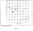
- the basic idea underlying the coarse proximity filter comprises partitioning the (x, y) plane into square cells. Preferably, for each probe, a separate grid of cells is defined. The predicted tracks generated during one STCA cycle are inserted into their corresponding grid. Preferably, two predicted tracks generated for probe p are called neighbours if both following conditions are satisfied: the tracks are in the same or an adjacent cell of grid p and their vertical separation is less than DZ_MAX.
- the coarse proximity filter preferably generates predicted pairs of neighbours. At the end of a cycle, the grids are emptied. This ensures that only pairs of predicted tracks of the same cycle are generated.
- Fig. 11 exemplarily shows a grid for a given probe, as well as two neighbours in adjacent cells in the (x, y) plane.
- the filter Whenever a new predicted track for probe p is received, the filter generates predicted pairs involving the track and its neighbours. The track is subsequently inserted in the corresponding cell of grid p. This sequential insertion mechanism of tracks into cells ensures that each predicted pair is generated only once (sequential filtering).
- the size EDGE of the cells and the maximum vertical distance DZ_MAX are chosen large enough to include all predicted pairs of potential concern. However, choosing these parameters too large implies that an excessive number of pairs are processed by the conflict category prediction algorithm and the system performance is degraded. It has to be noted that the optimal values of EDGE and DZ_MAX may vary with the probe. Later in the description a preferred method for determining optimal values of these parameters for each probe will be presented.
- the mode 3/A code selection filter eliminates all pairs in which one or both tracks do not have a selected code, depending on the mode of operation MODE.
- split tracks filter multi-radar tracking can produce duplicate system tracks for the same airframe, known as split tracks.
- split tracks arise from the garbling effect in the detected mode 3/A codes.
- Different radars may detect mode 3/A codes that differ by a few bits although they actually correspond to the same aircraft. Thus, it is an important feature to detect split tracks and eliminate pairs of such tracks in order to avoid the declaration of nuisance alerts.
- a pair of input tracks is considered to satisfy the split conditions if all the following conditions are satisfied: vertical separation ⁇ VSD; lateral separation ⁇ LSD; and mode 3/A code bit differences ⁇ SCD.
- a confirmation mechanism is added to the split conditions in order to take into account spurious track effects.
- a confirmation window records the result of the split conditions test of the last WINSIZE cycles. Two input tracks are considered as split and all corresponding predicted pairs are eliminated by the filter if and only if the pair of input tracks met the split conditions at least once in the last WINSIZE cycles.
- the pairs of input tracks meeting the split conditions are collected in a split pairs set.
- the confirmation windows are updated with the split pairs set and the latter is emptied.
- the grids of the coarse proximity filter are emptied, and/or the confirmation windows of the split filter are updated with the split pairs set and the latter is emptied (coarse filter clean up).
- conflict category prediction will be described in more detail.
- the basic idea of the conflict category prediction algorithm consists of predicting the conflict category of a predicted pair. All pairs whose predicted category is larger than a specified minimum category are eliminated. Finally, conflicts are built from the remaining pairs.
- the conflict category of a pair is predicted by predicting a major or minor separation infringement for the pair and/or applying the crossing and divergence tests to the mean positions and speed vectors of the predicted tracks in the pair (as has been discussed in detail above).
- a stochastic model for minimum separation infringement has been developed from the mean positions and error variance vectors of the predicted tracks in a pair in order to predict separation infringements.
- probabilities of major and minor separation infringements are compared to a given threshold.
- the stochastic model is decomposed to lateral and vertical models.
- a pair of predicted tracks T 1 and T 2 is considered to be generated for probe p. It is now an object to estimate the probability of a lateral separation infringement between T 1 and T 2 .
- the first task consists of determining the two-dimensional stochastic model of the combined lateral positional error of the pair (T 1 , T 2 ). The probability of lateral separation infringement is then approximated by a one-dimensional stochastic model.
- ⁇ 1 2 E ⁇ e 1 ⁇ 2 2
- ⁇ 2 2 E ⁇ e 2 ⁇ 2 2 denote their respective lateral error variances.
- Fig. 12 shows lateral predicted tracks with error vectors and variances in the (x, y) plane.
- d denotes the distance between the mean lateral positions of T 1 and T 2 , e the combined positional error vector, ⁇ 2 the combined lateral error variance and d min the minimum distance below which a lateral separation infringement occurs.
- d denotes the distance between the mean lateral positions of T 1 and T 2 , e the combined positional error vector, ⁇ 2 the combined lateral error variance and d min the minimum distance below which a lateral separation infringement occurs.
- the probability of lateral separation infringement is the probability that the vector d + e lies inside the circle centred at 0 and of radius d min .
- the first task consists of determining the stochastic model of the combined vertical positional error of the pair (T 1 , T 2 ). The probability of vertical separation and infringement is then calculated.
- e 1 and e 2 are the vertical positional errors of T 1 and T 2 .
- ⁇ 1 2 E ⁇ e 1 ⁇ 2 2
- ⁇ 2 2 E ⁇ e 2 ⁇ 2 2 denote their respective vertical error variances.
- the distribution function of e is a normal distribution with mean 0.
- d denotes the distance between the mean vertical positions of T 1 and T 2 , ⁇ 2 the combined vertical error variance and d min the minimum distance below which a vertical separation infringement occurs.
- the probability of vertical separation infringement is the probability that the normal random variable u of mean d and variance ⁇ 2 lies in the interval [-d min , d min ] as illustrated in Fig. 14.
- d 1 and d v are considered to be the distances between the lateral and the vertical positions of the predicted tracks in the pair.
- p(a, b) is the probability that d 1 ⁇ a and d v ⁇ b.
- p min is a threshold probability value.
- a separation infringement is preferably predicted as follows: If p(DL_MAJOR, DV_MIN) ⁇ p min , a major separation infringement is predicted; If p(DL_MAJOR, DV_MIN) ⁇ p min and p(DL_MINOR, DV_MIN) ⁇ p min , a minor separation infringement is predicted;
- the threshold p min depends on the prediction time frame as well as the combined region type of the predicted pair, as discussed above. Further in the specification, a method will be presented which restricts the interval of possible values of p min . This method is based on the concept of so-called conflict patterns.
- a conflict is preferably computed from the set S of predicted pairs of two given aircraft whose predicted conflict category is less than or equal to a region type parameter CAT_MAX.
- the preferred conflict attributes are determined as follows:
- the size EDGE of the cells and the maximum vertical distance DZ_MAX are preferably chosen large enough to include all predicted pairs of potential concern. However, choosing these parameters too large implies that an excessive number of pairs are processed by the conflict category prediction algorithm and degrades system performance. Furthermore, the optimal values of EDGE and DZ_MAX may vary with the probe.
- Optimal values meeting this condition are based on some worst case values of: the minimum distance d min , above which there is no separation infringement, the threshold probability p min for separation infringement prediction; and/or the maximum combined error variance ⁇ max 2 of the trajectory prediction.
- the optimal separation is derived as a function of the parameters d min , p min and ⁇ max ⁇ Then, for the lateral and vertical cases, the worst case values of these parameters are calculated. Finally, an example is presented showing the evolution of the parameters EDGE and DZ_MAX with the probe.
- u is considered to be a normal random variable of mean d ⁇ 0 and variance ⁇ 2 .
- u* denotes the standard normal random variable of mean 0 and variance 1.
- u ⁇ u* + d.
- the standard error ⁇ is preferably assumed to satisfy the relation 0 ⁇ ⁇ ⁇ ⁇ max .
- the parameters d min , p min and ⁇ max preferably depend on the region type. Since the coarse proximity filter parameters EDGE and DZ_MAX are independent of the region type, worst case values for d min , p min and ⁇ max in the set SR of all region types have to be found.
- p min minimum P_MIN_SHORT in SR.
- p min minimum P_MIN_MEDIUM in SR.
- p min minimum P_MIN_LONG in SR.
- the worst case values of parameters d min and ⁇ max are preferably determined as follows for each probe.
- MAX_SPEEDLAT denote an upper bound on the lateral speed.
- ⁇ LS max (LS_INTERCEPT, LS_SLOPE ⁇ MAX_SPEEDLAT 2 + LS_INTERCEPT);
- ⁇ LM max (LM_INTERCEPT, LM_SLOPE ⁇ MAX_SPEEDLAT 2 + LM_INTERCEPT);
- ⁇ L max (0, ⁇ LS , ⁇ LM ).
- ⁇ max maximum (probe ⁇ (2 ⁇ L ) 1/2 ) in SR.
- the worst case values of parameters d min and ⁇ max are preferably determined as follows for each probe.
- MAX_SPEEDVERT denote an upper bound on the vertical speed.
- ⁇ max maximum (probe ⁇ (2 ⁇ V ) 1/2 ) in SR.
- EDGE and DZ_MAX start with a preferred value d min for probe 0, grow until probe 30 seconds, decrease and stabilize at d min for probe 70 seconds.
- tables 12 to 17 present preferred specification as well as preferred values of preferred parameters specific to STCA.
- Table 12 shows the specification of coarse proximity filter parameters
- table 13 shows the specification of mode 3/A code selection filter parameters
- table 14 shows the specification of split tracks filter parameters
- table 15 shows the specification of combined region type parameters
- tables 16 and 17 show region type parameters wherein table 16 shows the specification of region definition parameters and table 17 shows the specification of conflict prediction parameters depending on region type of STCA.
- DZ_MAX is determined automatically 50 Fl MAX_SPEEDLAT Maximum lateral speed (for automatic determination of EDGE) 0.18 NM/sec MAX_SPEEDVERT Maximum vertical speed (for automatic determination of DZ_MAX) 1 Fl/sec Specification of Mode 3/A Code Selection Filter Parameters of STCA Parameter Description
- Example MODE Mode of operation At least one track in pair has selected code CODE Mode 3/A code 4324 SELECT CODE selected ?
- conflict patterns consists of imposing the behaviour of the STCA system in defined situations.
- a conflict pattern defines a set of scenarios for which the output of STCA is specified. Two classes of conflict patterns can be identified, depending on whether or not a conflict alert is desired for the pattern. A conflict pattern for which an alert is desired will be called positive conflict pattern, whereas a conflict pattern for which an alert is not desired will be called negative conflict pattern.
- a preferred idea is to impose restrictions on the interval of possible values of the minimum confidence level function p min (t). Positive conflict patterns will impose restrictions on the upper bound of p min , whereas negative conflict patterns will restrict the lower bound of p min . Note that it will not always be possible to find a function p min (t) which is adequate for all conflict patterns in a given set. Indeed, the upper bound of p min imposed by a positive conflict pattern may be smaller than the lower bound imposed by a negative conflict pattern, resulting in a contradiction.
- conflict pattern if the behaviour of the STCA system in given scenarios shall be imposed, then the latter must be predictable by STCA. For example, a scenario containing a late manoeuvre is not predictable by STCA. In this case, the predicted aircraft separation will not correspond to the actual minimum aircraft separation of the scenario. However, imposing conditions based on aircraft separations requires that the latter be predictable. Therefore, conflict patterns will exclusively define sets of scenarios for which the aircraft 3-D speed vectors remain constant.
- a conflict pattern is preferably defined by the following information:
- the maximum prediction time is only relevant for positive conflict patterns. It specifies the prediction time above which STCA is not required to yield a conflict alert.
- the information of whether an aircraft is levelled or climbing/descending determines which error variance model is used in the vertical trajectory prediction of STCA.
- the attributes d l and d v correspond to the lateral and vertical aircraft separations at any time in the prediction time frame.
- the minimum lateral aircraft speed v l, min is used only for negative conflict patterns.
- the minimum vertical speed for a climbing/descending aircraft is implicitly defined as the maximum vertical speed for a levelled aircraft v v, level, max .
- the CD flag is used to determine the minimum lateral separation above which there is no lateral separation infringement. If the flag is set to TRUE, this minimum is given by the parameter DL_MAJOR. Otherwise, it is given by the parameter DL_MINOR.
- p min (t) be defined as a piecewise constant function with three distinct values for short, medium and long term prediction time frames, i.e.,
- p min U (t) be the upper bound of p min (t) restricted by a positive conflict pattern.
- P_MIN_SHORT ⁇ min ⁇ p min U (t) 0 ⁇ t ⁇ SHORT_TERM ⁇
- P_MIN_MEDIUM ⁇ min ⁇ p min U (t) SHORT_TERM ⁇ t ⁇ MEDIUM_TERM ⁇
- p min L (t) be the lower bound of p min (t) restricted by a negative conflict pattern.
- Table 18 shows the restricted intervals for the function p min (t) imposed by a set of positive and negative conflict patterns in upper airspace. The following values for the parameters defining the safety cylinder centered at each aircraft are assumed:
- Table 19 shows the restricted intervals for the function p min (t) imposed by a set of positive and negative conflict patterns in TMA. The following values for the parameters defining the safety cylinder centered at each aircraft are assumed:
- MSAW minimum safe altitude warning
- a minimum safe altitude warning (MSAW) system is a safety net aimed at predicting minimum safe altitude violations in a near future and warning the radar controller of this potential danger. This example is based on the generic specification, design and algorithms which are applicable to all safety nets and are discussed above in detail and thus describes solely the aspects which are specific to the MSAW safety net.
- conflict In the context of the MSAW safety net, the notion of conflict as defined above corresponds to a minimum safe altitude violation.
- the uncertainty of a conflict is based on the uncertainty of trajectory prediction, in which errors are unavoidable, as discussed above. This uncertainty will be represented by a stochastic model for minimum safe altitude violation.
- the generic conflict prediction module as defined above predicts a minimum safe altitude violation of a predicted track and generates conflicts. In the latter preferred model, a probability of minimum safe altitude violation is estimated.
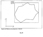
- MSAW regions are defined by a minimum safe altitude and/or a maximum altitude of potential concern, above which aircraft are considered to be in no danger of coming into close proximity with the minimum safe altitude within the prediction time frame.
- the maximum altitude of potential concern is preferably specified by a single maximum altitude MAPC, which is preferably valid for the whole region.
- the minimum safe altitude is preferably specified in any of the following ways (see Fig. 17):
- manoeuvre regions do not contain the additional attributes defined here above.
- the mode 3/A code selection specifies which codes have to be protected by the MSAW function.
- the information preferably required in an input track is specified above.
- a conflict preferably comprises the following information, restricted to the prediction time frame: unique conflict identification, wherein contiguous conflicts for a given aircraft have the same conflict identification; duration of conflict identification; MSAW system identification (sic, sac); current time; time to conflict; lateral and vertical starting positions of conflict; current lateral and vertical distances to starting positions of conflict; predicted minimum altitude; probability of minimum safe altitude violation; and/or information about the aircraft involved in the conflict.
- the information about the aircraft preferably comprises: track identificationon; mode 3/A code; call sign, if available from input track; and/or track server identificationon (sic, sac).
- An input track T is eliminated if it does not have a selected mode 3/A code or, if, for each non-manoeuvre region, any of the following relations hold: Lateral distance of T to region > MAX_DIST_LAT; Vertical distance of T to region > MAX_DIST_VERT; and/or Altitude of T > MAPC; where MAPC denotes the maximum altitude of potential concern of the region.
- the distance to region it is noted that the distance of a point x to a set S is defined as the minimum distance of x to each point of S.
- m denotes the lateral position of T.
- the lateral distance d of T to a region R is preferably calculated as follows:
- a bounding box of a set S in R n is the cross product of n intervals which encloses the set S.
- conflict prediction the basic idea of the conflict prediction algorithm consists of predicting a minimum safe altitude violation of a predicted track. All predicted tracks that are not predicted to violate the minimum safe altitude are eliminated. Finally, conflicts are built from the remaining predicted tracks.
- the highest priority, non-manoeuvre region containing the mean position vector of the predicted track is determined; a stochastic model for minimum safe altitude violation for this region is developed from the mean position and error variance vectors of the predicted track. In this model, a probability of minimum safe altitude violation is compared to a minimum confidence level.
- the stochastic model is preferably decomposed into lateral and vertical models.
- m denotes the mean lateral position of T
- d f the distance of m to the lateral frontier of R
- e the lateral positional error vector of T
- ⁇ 2 its lateral error variance
- u* is the standard normal random variable of mean 0 and variance 1. This probability is preferably obtained by standard normal distribution table look-up.
- m denotes the mean vertical position of T, e the vertical positional error of T and ⁇ 2 its vertical error variance, as is shown in Fig. 21.
- p 1 being the probability of lateral region penetration of T into R
- p v being the probability that the altitude of T is less than the minimum safe altitude of R at the mean lateral position of T
- these probabilities are preferably estimated as described above.
- p min is considered to be a threshold probability value.
- a minimum safe altitude violation is predicted if and only if the relation p tot ⁇ p min holds.
- the threshold p min depends on the prediction time frame as well as the region type of T as already discussed in detail above.
- the lateral geometry of a region is a polygon with a large number of edges, it may be useful to predict a minimum safe altitude violation for the minimum bounding box of the region. If no minimum safe altitude violation is predicted for this bounding box, there is no need to predict a minimum safe altitude violation for the region itself.
- a conflict is computed from the set S of predicted tracks of given aircraft for which a minimum safe altitude violation was predicted.
- the conflict attributes are preferably determined as follows:
- MSA_TYPE Type of minimum safe altitude (single minimum altitude, offset to terrain, obstacle region, sloping path) Single minimum altitude MSA Single minimum altitude 10 Fl OFFSET Offset to terrain 3 Fl ALPHA Vertical angle of sloping path 3 deg ALPHA_TOL Tolerance on angle ALPHA 1.4 deg RWY_LAT Latitude of runway threshold (for sloping path) 46:00:00 N RWY_LON Longitude of runway threshold (for sloping path) 15:00:00 E RWY_ALT Altitude of runway threshold (for sloping path) 300 meters
- the APW function/system is a safety net aimed at predicting penetrations of protected air space regions in a near future and warning the radar controller of this potential danger.
- the uncertainty of a conflict is based on the uncertainty of trajectory prediction and will be represented by a stochastic model for penetration depth of a protected region. In the latter model, a probability of protected region penetration is estimated.
- APW regions define aircraft access restrictions. For example,
- each APW region is defined by
- manoeuvre regions do not contain the additional attributes defined here above and are considered as non-protected regions.
- a conflict preferably comprises the following information, restricted to the prediction time frame: unique conflict identification, wherein contiguous conflicts for a given aircraft have the same conflict identification; duration of conflict identification; APW system identification (sic, sac); current time; time to conflict; lateral and vertical starting positions of conflict; current lateral and vertical distances to protected region; predicted minimum lateral and vertical distances to protected region; probability of protected region penetration; information about the aircraft involved in the conflict; and/or protected region identification.
- the information about the aircraft preferably comprises: track identification; mode 3/A code; call sign, if available from input track; and/or track server identification (sic, sac).
- the configuration parameters of the APW system which are common to all safety nets are specified above, e.g. in Tables 1 to 9. Preferred further or specific parameters to APW are specified below in Tables 20 and 21.
- An input track T is eliminated if, for each protected region within which T is not allowed to fly, any of the following relations hold: Lateral distance of T to region > MAX_DIST_LAT; Vertical distance of T to region > MAX_DIST_VERT. m denotes the lateral position of T. Please note that the distance of a point x to a set S is preferably defined as the minimum distance of x to each point of S.
- the lateral distance d of T to a region R can be calculated as follows:
- d is preferably substituted for the lateral distance of T to the minimum bounding box of R, as shown in Figure 18.
- a bounding box of a set S in R n is the cross product of n intervals which encloses the set S.
- conflict prediction the basic idea of the conflict prediction algorithm consists of predicting the penetration of a protected region by a predicted track. All predicted tracks that are not predicted to penetrate any protected region within which the aircraft is not allowed to fly are eliminated. Finally, conflicts are built from the remaining predicted tracks.
- the highest priority, non-manoeuvre region containing the mean position vector of the predicted track is preferably determined. If the latter region is a protected region within which the aircraft is not allowed to fly, a stochastic model for penetration of this region is developed from the mean position and error variance vectors of the predicted track. In this model, a probability of region penetration is compared to a minimum confidence level.
- the stochastic model is preferably decomposed in lateral and vertical models. Otherwise, the predicted track is eliminated.
- the APW reference can be made to the lateral stochastic model as discussed above with respect to e.g. the MSAW.
- m denotes the mean vertical position of T, [z min , z max ] the height band of R, e the vertical positional error of T and ⁇ 2 its vertical error variance, as can be seen in Fig. 22.
- a region penetration is preferably predicted if and only if the relation p tot ⁇ p min holds.
- the threshold p min preferably depends on the prediction time frame as well as the region type of T, as discussed above in detail.
- the lateral geometry of a protected region is a polygon with a large number of edges, it may be useful to predict a penetration of the minimum bounding box of the region. If the predicted track is not predicted to penetrate this bounding box, there is no need to predict a penetration of the region itself.
- a conflict is computed from the set S of predicted tracks of a given aircraft which are predicted to penetrate a given protected region within which the aircraft is not allowed to fly.
- the conflict attributes are preferably determined as follows:
- the present invention provides a reliable method and system for alerting of potentially hazardous situations in air traffic which fulfil the objects as defined above.
- the system and method assist the controller in his work and help him to better analyse complex traffic situations and take correct decisions in time. Further, the rate of nuisance alerts is reduced.
- the present invention may also be used with regard to other forms of traffic, such as rail traffic, e.g. trains, road traffic, e.g. cars, or sea traffic, e.g. ships or submarines, etc.
- rail traffic e.g. trains
- road traffic e.g. cars
- sea traffic e.g. ships or submarines
Abstract
Description
- The present invention relates to a system and a method for alerting of potentially hazardous situations in air traffic on the basis of surveillance data wherein predicted conflicts are identified based on the prediction of future air traffic situations.
- The ever growing air traffic increases the complexity of the air traffic picture and the pressure under which radar controllers work. Under such circumstances, it is desired to provide additional automated tools to assist the controller in his work, by helping him better analyse complex traffic situations and take correct decisions in time.
- Safety net are automated tools intended to alert controllers of potentially hazardous situations predicted in the near future. They are based on trajectories predicted from surveillance data.
- For example, the following main safety nets can be identified, as it is known from "Operational Requirements Document for EATCHIP Phase III; ATM Added Functions"; Vol. 2: Safety Nets; Edition 2.0; EUROCONTROL, 25/01/1999; Document Number: OPR.ET1.ST04.DEL01.2.
- The Short Term Conflict Alert (STCA) function, which predicts violations of defined separation criteria between two aircraft;
- The Minimum Safe Altitude Warning (MSAW) function, which predicts minimum safe altitude violations of an aircraft; and
- The Area Proximity Warning (APW) function, which predicts penetrations of protected airspaces by an aircraft.
-
- "Conflict Alert for the Support of Radar Control in MADAP"; EUROCONTROL Maastricht UAC, October 1990; Document Number: GD-0047-03 discusses the idea of discretizing prediction time frames into a number of time points, called probes. For each probe, the probing process generates a static traffic picture ("a snapshot") represented by a set of predicted tracks;
- "Operational Requirements for ETACHIP Phase III; ATM added Functions"; Vol. 2: Safety Nets; Edition 2.0; EUROCONTROL, 25/01/1999; Document Number: OPR.ET1.ST04.DEL01.2 discusses the expression of the nature of a conflict in terms of properties of the conflict as well as the definition of air space regions belonging to different region types;
- In "Conflict Probability Estimation for Free Flight"; Journal of Guidance, Control and Dynamics; Vol. 20; no. 3; May-June 1997; pp. 588-596, R.A. Paielli and H. Erzberger discuss a method to estimate the conflict probability for a pair of aircraft in free flight wherein the trajectory prediction errors are based on the assumption of constant airspeed (in both magnitude and direction) and on unpredictable variations in wind speed;
- Under normal circumstances a safety net is transparent to the controller. Whenever the system detects a potential danger in the near future, it displays an alert message. The controller can then identify an appropriate avoiding manoeuvre and communicate the instructions to the pilot(s) concerned. This means that the radar controller should not adopt a passive attitude by blindly relying on the safety net function and waiting until an alert is indicated to him;
- Air collisions and almost air collisions in the past and recent past confirm that, firstly, safety nets play a fundamental role to assist the controller's work in the ever growing air traffic and, secondly, there is considerable room for improvement in the design and implementation of safety nets. Quoting Jane's Airport issue of September 2002 "Safety Revamp Triggered"; Jane's Airport; Vol. 14; issue 7; September 2002, "The safety management culture of European ATM agencies will need an immediate overhaul".
- It is an object of the present invention to provide a method and a system for reliably alerting of potentially hazardous situations in air traffic which overcome the deficiencies and drawbacks of the methods and systems known in the state of the art. It is an additional or further object to provide a system and a method that allow to reliably detect potential dangers in the near future, to reliably communicate an alert message in time and/or which assist the controller's work. Furthermore or additionally, it is a preferred object to provide a system and method that allow that a minimum distance be held, a long-term surveillance, foresightedly behaviour and/or an adaptation of the method/system to the actual circumstances.
- These objects are solved by the features of the independent claims. The dependent claims relate to preferred embodiments and further aspects of the present invention.
- Before describing the present invention in detail, some general terms and features will be defined.
- In the following, a conflict is a violation of defined safety criteria involving one or more aircraft. A real conflict is a conflict that actually occurs. Such a conflict is a critical situation which may have dramatic consequences and should always be avoided. A predicted conflict is a conflict that is likely to occur in the near future. Such a conflict is based on a prediction of air traffic situation in the near future. Safety net functions and safety net systems according to the present invention identify both real and predicted conflicts, whereas the latter may be seen as a generalization of the former.
- Whereas the identification of a real conflict is a deterministic process, i.e., the decision of whether or not one or more aircraft are in real conflict is simply determined by the actual track data of the aircraft, the identification of a predicted conflict is not a deterministic process. The reason for this lies in the non-deterministic nature of future air traffic situation prediction in which errors are unavoidable. This is because aircraft may perform unexpected manoeuvres or change the speed in the prediction time frame etc. The farther in the future a prediction is made, the greater the prediction error.
- Since a safety net has to identify both real and predicted conflicts, as discussed above, it is a fundamentally non-deterministic process. According to the present invention a stochastic approach has been adopted in the design of a safety net algorithm, as will be described later in detail.
- Since the identification of predicted conflicts is based on the prediction of future air traffic situations a well-designed trajectory prediction scheme is a key to achieve an effective and efficient safety net algorithm.
- For the present invention the warning time of a conflict alert is defined as the time interval between the first communication of an alert and the start of the predicted violation of the safety criteria. Ideally, the warning time should be sufficiently large to cover the time needed by the radar controller to formulate an appropriate avoiding manoeuvre and communicate it to the pilot(s), plus the time need by the latter to perform a manoeuvre and eliminate the potential danger. However, unpredictable late manoeuvres might severely restrict the warning time by generating a predicted conflict in very short term.
- A basic idea of the present invention consists of defining a stochastic model for trajectory prediction in which the uncertainty of the prediction is represented as a function of the prediction time. The stochastic model(s) for predicting trajectories is preferably used to construct a stochastic model for conflict prediction. In the latter stochastic model, probabilities of conflict are compared to minimum confidence levels and allow to decide whether a given predicted situation is a predicted conflict or not.
- The minimum confidence level required to predict a conflict is defined as a function of the urgency of the conflict, expressed by its prediction time. This function is independent of the uncertainty of trajectory prediction.
- The ability to specify, for each prediction time, the minimum confidence level required to predict a conflict enables an optimal trade-off between in-time conflict prediction and nuisance alert rate. In contrast, this optimal trade-off is more difficult to achieve in a deterministic model which does not use any uncertainty information for trajectory prediction.
- In particular, the present invention provides a safety net method or method for alerting of potentially hazardous situations in air traffic on the basis of surveillance data wherein predicted conflicts are identified based on the prediction of future air traffic situations by definition of a stochastic model for trajectory prediction in which the uncertainty of the prediction is preferably based on a variable aircraft 3D speed vector and is represented as a function of the prediction time. Further, preferably at least one stochastic model of predicted trajectories is used for constructing a stochastic model for conflict prediction in this method.
- Preferably, the probabilities of conflict are compared to minimum confidence levels, wherein a decision is made whether a predicted situation is a predicted conflict or not based upon this comparison to minimum confidence levels.
- The method preferably defines a minimum confidence level for predicting a conflict as a function of the urgency of the conflict, expressed by its prediction time. Further, a time interval between a first communication, e.g. by displaying etc., of an alert and the start of the predicted violation of the safety criteria is preferably sufficiently large to cover the time needed by a radar controller to formulate an appropriate avoiding manoeuvre and communicate it to the pilot(s) plus the time needed by the latter to perform the manoeuvre and eliminate the potential danger.
- According to a preferred or further feature of the present invention different air space regions are considered in order to cope with different flight activities and conflict thresholds. Accordingly, each air space region is classified to belong to a region type. Preferably, each region type has a different set of trajectory prediction and conflict prediction parameters and hence different stochastic models for trajectory and conflict prediction.
- According to a further feature of the invention a new class of region types, called manoeuvre region types, has been introduced in addition to the standard region types. Regions of these types are centred at points in the vicinity of which aircraft are expected to perform a manoeuvre. These points preferably correspond to VORDME (Very High Frequency Omnidirectional Radio Range Distance Measuring Equipment) and NDB (Non Directional Beacon) way points. Such manoeuvre regions are aimed at predicting aircraft manoeuvres.
- When an aircraft enters a manoeuvre region, it is expected to perform a manoeuvre in the near future, and the uncertainty of the trajectory prediction is automatically increased.
- Preferably, a different set of trajectory parameters is used and the uncertainty of the trajectory prediction is adapted according to the respective region types and the properties (e.g. position) of the respective aircraft(s).
- Preferably, the method steps are repeated in cycles wherein a confirmation window records the conflicts of the last cycles and wherein, at the end of one cycle, the confirmation windows are updated with the conflicts predicted during this cycle. Further, a conflict is confirmed and communicated if the conflict was predicted at least c times in the last cycles and wherein the parameter c depends on the prediction time frame and the region type of the aircraft involved in the conflict.
- The method is suitable for all main safety nets such as, i.a., Short Term Conflict Alert (STCA), Minimum Safe Altitude Warning (MSAW) and/or Area Proximity Warning (APW) wherein the method may be adapted in order to fulfil special requirements of one or more safety nets.
- Accordingly, the method is preferably suitable for predicting violations of defined separation criteria between at least two aircraft, for predicting minimum safe altitude violations of at least one aircraft, and/or for predicting penetrations of protected airspaces by at least one aircraft as well as for predicting other violations of safety criteria in air traffic.
- Further, the present invention provides a safety net system or system for alerting of potentially hazardous situations in air traffic comprising a surveillance data detection and processing means wherein predicted conflicts are identified based on the prediction of future air traffic situations by a stochastic control means which defines a stochastic model for trajectory prediction in which the uncertainty of the prediction is represented as a function of the prediction time. Further, preferably at least one stochastic processing and control means for predicted trajectories constructs a stochastic model for conflict prediction. The conflict is further preferably communicated by a conflict communication means.
- Further additional and preferred features of the system correspond to the features and preferred features of the method, as discussed above and below.
- The system according to the present invention for alerting of potentially hazardous situations in air traffic preferably comprises: structures or data structures, such as an input track, which contains all input track information relevant to the safety net; a trajectory, i.e., a 3D trajectory for one aircraft; a predicted track, which is an extrapolation of an input track; and/or a conflict, which is the safety net output containing all relevant conflict information as well as statistical data which are all data useful for a statistical analysis of the system. Preferably the system further comprises the data structure region type, which is a set of safety net parameters that depend on the region type.
- The system further preferably comprises the following main modules: input track filtering, which eliminates input tracks which do not satisfy certain selection criteria; trajectory prediction, which generates predicted trajectories from input tracks; trajectory probing, which discretizes the prediction time frame into a finite number of time points and generates a predicted track on a given trajectory for each such time point; a conflict prediction, which performs conflict prediction on predicted tracks and which is specific to each individual safety net; a conflict confirmation which confirms conflicts over several input track updates and/or online statistical data collection, which collects online statistics and analyses the performance of the safety net systems. Preferably, the system further comprises the main module region type identification, which identifies the region type of an input track by determining the air space region containing the track.
- Preferably, the input of a safety net function is essentially based on radar data and does not require continuous inputs from the radar controller for its proper functioning. However, in order to reduce the number of nuisance alerts and avoid warning the radar controller of a situation he already resolved, the system preferably also makes use of aircraft intention information, e.g. cleared flight levels, provided by a flight plan or controller input etc.
- In the following the present invention will be described in further detail with reference to the drawings, in which:
- Fig. 1 shows a safety net interface;
- Fig. 2 shows a generic safety net data flow diagram;
- Fig. 3 shows a generic safety net state diagram;
- Fig. 4 shows mean lateral trajectory and error variance;
- Fig. 5 shows mean vertical trajectory, assigned level and error variance;
- Fig. 6 shows lateral position, speed and error variance of predicted tracks;
- Fig. 7 shows vertical position, speed and error variance of predicted tracks;
- Fig. 8 shows a minimum probability as a function of the conflict urgency;
- Fig. 9 shows a piecewise constant function for minimum probability;
- Fig. 10 shows a data flow diagram of the conflict prediction module of STCA;
- Fig. 11 shows grid and neighbours of STCA;
- Fig. 12 shows lateral predicted tracks with error vectors and variances of STCA;
- Fig. 13 shows combined positional error and separation infringement of STCA;
- Fig. 14 shows the probability of separation infringement of STCA;
- Fig. 15 shows vertical predicted tracks with error vectors and variances of STCA;
- Fig. 16 shows optimal coarse proximity filter parameters for each probe of an example of STCA;
- Fig. 17 shows a minimum safe altitude specification of MSAW;
- Fig. 18 shows region and minimum bounding box of MSAW;
- Fig. 19 shows lateral predicted track and region of MSAW;
- Fig. 20 shows probability of region penetration of MSAW;
- Fig. 21 shows vertical predicted track and region of MSAW;
- Fig. 22 shows vertical predicted track and protection region of APW.
-
- In order to cope with different flight activities and conflict thresholds the safety net, i.e. the method and system according to the present invention, preferably consider different air space regions, representing volumes of air space. Each air space region has a region type. Each region type is defined by or is represented by a different set of trajectory prediction and conflict prediction/confirmation parameters.
- In addition to the standard region types a new class of region types, called manoeuvre region types is preferably introduced. As already discussed above, regions of these types are centered at points in the vicinity of which aircraft are expected to perform a manoeuvre. These points preferably correspond to VORDME (Very High Frequency Omnidirectional Radio Range Distance Measuring Equipment) and NDB (Non Directional Beacon) way points. Such manoeuvre regions are aimed at predicting aircraft manoeuvres. When an aircraft enters a manoeuvre region, it is expected to perform a manoeuvre in the near future. Therefore, a different set of trajectory prediction parameters is used and the uncertainty of the trajectory prediction is automatically increased.
- According to the above, region types preferably are divided into the two classes, standard region types and manoeuvre region types. Examples of standard region types are "Upper En-Route Control Areas" (upper CTA), "Lower En-Route Control Areas" (lower CTA) or "Outer Terminal Air Spaces", "Terminal Manoeuvre Areas" (TMA), "Control Zones" (CTA) and/or "Stacks" (holding areas).
- Standard region types are preferably defined by a unique region type identifier, a set of trajectory prediction parameters and/or a set of conflict prediction/confirmation parameters.
- Manoeuvre region types are preferably defined by a unique region type identifier, a set of trajectory prediction parameters and/or a reference to a standard region type, called base type. The manoeuvre region type inherits the conflict prediction/confirmation parameters from its base type.
- Each air space region is preferably defined by the attributes: "unique region identifier", "unique region type identifier", "lateral geometry of the region", "height band of the region", "region priority", "activity flag" and/or "exclusion flag".
- A region has preferably one of the following lateral geometries. A region can have the lateral geometry of a simple closed polygon, defined as a list of vertices. It is noted that standard geometrical algorithms are preferably used to determine whether a point lies in a simple closed polygon. A region may further have a lateral geometry of a distance radius circle, defined by a centre and a distance radius. Further, a region can have the geometry of a time radius circle, defined by a centre and a time radius. An aircraft is considered to belong to a time radius circle if the condition
- An aircraft is preferably considered to belong to a manoeuvre region whenever it is expected to perform a manoeuvre in the vicinity of the centre of this region in the maximum prediction time. Therefore, manoeuvre regions are preferably represented by time radius circles and the time radius of the circle is preferably close or proportional to the maximum prediction time.
- The lower or upper heights of a region are preferably specified as altitudes and/or as flight levels.
- It is to be noted that regions can be included in or overlap other regions. Hence, an aircraft can fall within more than one defined region. In this case, the region with the highest priority is selected.
- The activity flag of a region determines whether the region is active, i.e., if it has to be considered by the safety net. The exclusion flag specifies whether the safety net function is inhibited in the region. The activity and exclusion flags may preferably be changed dynamically. Finally, regions may preferably be defined dynamically.
- For receiving input, as discussed above, the safety net comprises a safety net interface. Such interface of any safety net function preferably comprises the following data structures, as is shown in Fig. 1. The input track data structure comprises all input track information relevant to the safety net. A conflict data structure is a safety net output containing all relevant conflict information and the parameters are configuration parameters of the safety net system.
- In more detail, the input track comprises data such as: track identification; mode 3/A code; call sign, if available from flight plan data; lateral position; mode C; sea level mode C or aircraft altitude; lateral speed vector; lateral manoeuvre indication, with direction and rate of turn; vertical manoeuvre indication, with direction and rate of climb/decent; current time; cleared (assigned) flight level, if available; and/or Reduced Vertical Separation Minimum (RVSM) compliance flag, if available from flight plan data.
- It should be noted that the sea level mode C or aircraft altitude are preferably suitable for air space regions whose lower or upper height bands are defined as an altitude. As a preferred embodiment the following relation between aircraft altitude, aircraft mode C and sea level mode C is used:
- The sea level mode C can be obtained from a QNH pressure value, assumed to be available from elsewhere in the system.
- In the following, the data structures, modules, parameters and main algorithm of the safety net, i.e. the method and system according to the present invention is discussed in more detail. Further, data flow and state diagrams of the method and the system are discussed.
- The method and system, e.g. suitable for the STCA, MSAW, APW etc. preferably comprises the following data structures: an input track, which contains all input track information relevant to the safety net; a trajectory, i.e., a 3D trajectory for one aircraft; a predicted track which is preferably the extrapolation of an input track; a conflict, which is the safety net output containing all relevant conflict information; the region type, which is a set of safety net parameters that depend on the region type; and/or statistical data, which are all data useful for statistical analysis of the system.
- Further, a safety net function is preferably composed of one or more of the following main modules: a region type identification, which identifies the region type of an input track by determining the air space region containing the track; an input track filtering, which eliminates input tracks which do not satisfy certain selection criteria; a trajectory prediction, which generates predicted trajectories from input tracks; a trajectory probing, which discretizes a prediction time frame into a finite number of time points and generates a predict track on a given trajectory for each such time point; a conflict prediction, which performs conflict prediction on predicted tracks and which is preferably specific to each individual safety net; a conflict confirmation, which confirms conflicts over several input track up dates; and/or an on-line statistical data collection which collects online statistics and analyses the performance of the safety net system.
- The configuration parameters of the safety net according to the present invention preferably comprise: general safety net parameters; communication parameters; input track filtering parameters; trajectory probing parameters; conflict prediction parameters; region definition parameters; and/or region type parameters.
- The region type parameters preferably comprise all safety net parameters whose values depend on the region type. These parameters comprise: trajectory prediction parameters; conflict prediction parameters; and/or conflict confirmation parameters.
- It is to be noted that one or more of the input track filtering and/or conflict prediction parameters depend on the safety net concerned. The remaining parameters are common to all safety nets and are specified later in the description.
- Fig. 2 shows the generic data flow diagram representing the main modules of preferred safety net functions and the corresponding data links as well as the configuration parameters of the safety net.
- As can be seen from Fig. 2 the input track filtering module receives input track data containing all input track information relevant to the safety net and eliminates input tracks which do not satisfy certain selection criteria based on input track filtering parameters, then passing all relevant track information to the trajectory prediction module. The region type identification module identifies the region type of an input track by determining the air space region containing the track based on the input track data and thus, identifies the region type data, i.e. the set of safety net parameters that depend on the region type. The region type identification module and identification process is further based on region definition parameters and region type parameters, wherein the region type parameters contain all safety net parameters whose values depend on the region type, as discussed above.
- The trajectory prediction module generates predicted trajectories from input tracks such as the output of the input track filtering module and the region type identification module, i.e. input track data and region type data. The predicted trajectories of the trajectory prediction module, i.e. the trajectory data, which is the 3D trajectory for one aircraft, is communicated to the trajectory probing module which discretizes the prediction time frame into a finite number of time points and generates a predicted track on a given trajectory for each such time point, i.a. based on trajectory probing parameters. The predicted track generated by the trajectory probing module is received by the conflict prediction module which further receives region type data and conflict prediction parameters and then performs conflict prediction on the predicted tracks. The conflict prediction module and the conflict prediction are specific to each individual safety net. The output of the conflict prediction module, i.e. the conflict data are confirmed by the conflict confirmation module over several input track updates and preferably the region type data. The output of the conflict confirmation module is the conflict data as the safety net output containing all relevant conflict information.
- During the above process the on-line statistical data collection module collects on-line statistics and analyses the performance of the safety net system. Further parameters received by the safety net are, e.g. general safety net parameters and/or communication parameters.
- The generic safety net algorithm will now be described in more detail.
- Preferably, the safety net function reads a preferably continuous stream of input tracks, received from e.g. the radar tracking system, for example by means of a UDP (User Datagram Protocol) communication medium. The safety net may be considered as a cyclic algorithm that performs conflict prediction on a set of input tracks whose time stamps differ by less then TAU, where TAU denotes the cycle time of the safety net. Preferably, TAU is approximately 4 to 6 seconds. Whenever a new track T is received, the algorithm starts by checking if the system is still in the current cycle, i.e. it tests for the condition
- If a new cycle has been entered, the internal data structures of the safety net are cleaned up. The set of conflicts SC is then confirmed with conflicts of the previous cycles. Finally, t0 is updated to t and SC is set to the empty set.
- Then, in both cases, i.e. the case of current and new cycle, the type of air space region containing T is identified. The input track filter checks whether T is a valid track. If not, the algorithm drops T and waits for the next track. Otherwise, the trajectory predictor generates a trajectory TR from T. The trajectory probing module then produces a set of predicted tracks ST on the predicted trajectory TR. The conflict prediction module subsequently generates conflicts involving the predicted tracks in ST and inserts these conflicts in the set SC of conflicts of the current cycle. It also stores the set ST in its internal data structures. Finally, statistical data is collected.
- In the initialisation phase of the algorithm, SC is set to the empty set and t can be set to any valid time value.
- The cycle time TAU is preferably determined by minimizing the time before confirming and hence communicating a conflict, under the constraint that all pairs of tracks are considered within one cycle. Therefore, TAU is equal to the time between two successive updates of a given track.
- Fig. 3 represents the generic safety net state diagram of safety net functions as discussed above.
- Regarding the input track filtering module, the input track filter eliminates all input tracks which do not satisfy certain selection criteria, as already indicated above. Preferably, an input track is eliminated if any of the conditions "it is in no defined region" and/or "it is in an exclusion region" apply.
- For an aircraft with temporary loss of mode C, height information is preferably obtained by extrapolation of the last mode C readout. The extrapolated height is considered invalid and the input track is eliminated if its last mode C readout was more than a certain time MAX_T_LAST_ MODEC ago.
- In the following, the trajectory prediction will be discussed in more detail. By definition, trajectory prediction is an approximation process which inevitably leads to positional errors. In order to account for these errors, a stochastic model for trajectory prediction has been defined, in which the uncertainty of the prediction is represented as a function of the prediction time. Trajectory prediction comprises or can be decomposed into prediction in the lateral plane and prediction on the vertical axis. Preferably, these two predictions are performed separately.
- For manoeuvring aircraft, the mean trajectory in the lateral plane is preferably determined by means of a standard turn angle which preferably depends on the region type. For non-manoeuvring aircraft, the mean trajectory is preferably obtained by linear extrapolation of the current lateral speed vector.
- The mean trajectory on the vertical axis is preferably determined by linear extrapolation of the current vertical speed. When an intended or assigned flight level is available, e.g. from controller input, flight plan data or some other source, and the aircraft is climbing or descending, the stochastic model is modified to take into account the clipping of the aircraft at the assigned flight level.
- Preferably, the uncertainty of the prediction is modelled as a function of the prediction time and the aircraft speed, and preferably further depends on the region type concerned as well as on the aircraft attitude, i.e. whether the aircraft is manoeuvring or not.
- In the rest of the document, it will be assumed for simplicity that the time of the current cycle t0 is equal to 0, so that the relative prediction time t-t0 is the same as the absolute prediction time t. As already indicated above, a trajectory is preferably composed of (1) a lateral trajectory in the space (t, x, y) and (2) a vertical trajectory in the space (t, z). Further, lateral and vertical trajectories are stochastic functions defined by (1) a mean, i.e. most likely, trajectory and (2) an error variance.
- The error variance models the uncertainty of the prediction. A preferred error variance will be described in detail below. Preferably e = e (v, t) denotes the lateral (resp. vertical) positional error vector at prediction time t for a lateral (resp. vertical) speed v. The error variance σ2 is defined as the mean or expectation of the square Euclidian norm of e(v, t):
- The square root σ of the error variance is called the standard error.
- In this model, it is assumed that ∥e(v, t)∥2 can be written as :where a = α2 and b = Er2. The parameters a and b, respectively, are called the slope and the intercept of the error variance model. They are determined by minimizing the variance

- The parameters a and b depend on the region type and/or the aircraft attitude, i.e., whether the aircraft is manoeuvring or not. Further below, a method for estimating these parameters from the analysis of the real track data will be discussed.
- In the following a preferred method for prediction in the lateral plane will be discussed. In the lateral plane, at least two cases have to be taken into consideration when determining the trajectory model. In the first case (1), the aircraft is following a straight line whereas in the second case (2), the aircraft is manoeuvring.
- When the aircraft follows a straight line, the mean lateral trajectory is preferably obtained by linear extrapolation of the current lateral speed vector.
- When the aircraft is manoeuvring, the mean lateral trajectory is preferably obtained by generating a circular trajectory with a current lateral speed and turn rate of the aircraft until the predicted end of the manoeuvre, followed by a tangent straight line. For this prediction a crucial or difficult task is the estimation of how long the aircraft will perform its manoeuvre. As a preferred solution, a standard angle of turn, TURNANGLE, given as a region type parameter, is introduced. Further, preferably the angle of turn already achieved by the aircraft is kept track. The remaining angle of turn is thus determined as:
- A preferred method for determining an optimal value of TURNANGLE for each region type will be discussed later in the description.
- In the stochastic model for trajectory prediction it is preferably assumed that the distribution function of the lateral positional error vector e = (ex, ey) is a normal distribution with mean 0 which is independent of the direction of the vector e. Such assumption has the advantage of providing a stochastic model for the distance between the lateral positions of two aircraft which does not depend on the direction of the relative lateral position of the aircraft. This assumption also justifies the definition of the error variance σ2, as given above. In the first case (1), i.e. the aircraft is following a straight line, the parameters a and b of the error variance σ2 are denoted as follows:
- Fig. 4 shows a mean lateral trajectory generated for a manoeuvring aircraft in the (x, y) plane. It is composed of a circular arc followed by a tangent straight line. The figure also represents the error variance σ2 as a function of the prediction time t.
- Now a preferred prediction on the vertical axis will be described. On the vertical axis, at least three cases have to be taken into consideration when determining the trajectory model, i.e., (3) the aircraft is levelled; (4) the aircraft is climbing or descending and an assigned, i.e. intended, flight level is available; and (5) the aircraft is climbing or descending and no assigned flight level is available.
- If the aircraft is levelled or no intended flight level is available, the mean vertical trajectory is preferably determined by linear extrapolation of the current vertical speed.
- When a valid assigned flight level is available, e.g. from controller input, flight plan data or some other source, and the aircraft is climbing or descending, the mean vertical trajectory and the error variance σ2, as defined above, need to be modified to take into account the clipping of the aircraft at the assigned flight level.
- It is assumed that the target will occupy the assigned level za within some tolerance interval [za - FL_TOL, za + FL_TOL]. The uncertainty interval [zmin, zmax] is preferably defined by
- A new standard error σ* is preferably used to take into account the assigned level:
- The predicted mean vertical position is given by
- In the stochastic model for trajectory prediction it is assumed that the distribution function of the vertical positional error is a normal distribution with mean 0 and variance σ*2.
- In case of a temporary loss of mode C information, the prediction must preferably be started at the time of the last mode C readout instead of the current time.
- In case (3), i.e., the aircraft is levelled, the parameters a and b of the error variance σ2 are denoted as follows:
- Fig. 5 shows the mean vertical trajectory generated for a climbing aircraft with an assigned flight level in the (t, z) plane, which comprises three line segments. The newly introduced standard error σ* is considered as well as the tolerance interval [za - FL_TOL, za + FL_TOL].
- In the following, preferred trajectory probing will be discussed in more detail. The basic idea of trajectory probing consists of discretizing the prediction time frame into a finite number of equally spaced time points, called probes. For each probe, the probing process generates a static traffic picture ("a snapshot") represented by a set of predicted tracks.
- This probing approach has, i.a., the important advantages that it provides a clear separation between movement and conflict prediction, that it substantially reduces the complexity of the conflict prediction module which can work with static traffic pictures and does not have to deal with time-dependent 4D-trajectories, thus avoiding complex equations of movement, that it provides a simple stochastic model at each probing point and that it is very simple conceptually.
- Preferably, a predicted track is defined by: a track identification; a probe; a position vector; and/or a speed vector (vx, vy, vz). The position vector is a stochastic variable, preferably defined by: a mean position vector (x, y, z) and/or an error variance vector (σxy 2, σz 2).
- In order to characterize the proximity of a probe, at least three prediction time frames will be defined. According to preferred prediction time frames a probe p is in a short term prediction time frame if
- Preferred approximated values for these parameters are : SHORT_TERM = 30 seconds, MEDIUM_TERM = 60 seconds, and/or LONG_TERM = 120 seconds.
- The probing process generates a number, NBPROBES, of preferably equally spaced probes in the interval [0, LONG_TERM]. For a given trajectory, the probing process determines, for each probe p, the following predicted track:
- mean position vector (x, y, z);
- speed vector (vx, vy, vz); and/or
- error variance vector (σxy 2, σz 2).
-
- For the mean position vector (x, y, z) the vector (x, y) is the position on the mean lateral trajectory at p and the height z is the position on the mean vertical trajectory at p. Regarding the speed vector (vx, vy, vz), the norm of the vector (vx, vy) is equal to the norm of the current lateral speed vector and its direction is parallel to the mean lateral trajectory at p. Further, the rate vz is equal to the slope of the mean vertical trajectory at p. For the error variance vector (σxy 2, σz 2), σxy 2 is the error variance of the lateral trajectory at ((vx 2 + vy 2)1/2, p) and σz 2 is the error variance of the vertical trajectory at (vz, p).
- Figs. 6 and 7 exemplary show graphically the predicted tracks generated for NBPROPES = 8 probes. In particular, Fig. 6 shows the lateral position in the (x, y) plane as well as speed (vx, vy) and error variance (σxy 2) of predicted tracks for probes 0 to 7. Fig. 7 shows the vertical position (z, t), speed (vz) and error variance (σz 2) of predicted tracks for probes 0 to 7.
- Preferably, a number of probes NB_PROBES should be large enough to neglect the discretization error. On the other hand, making the number of probes too small deteriorates the system performance. Therefore, a good trade-off has to be found between discretization error and system performance.
- Conflict prediction will now be discussed in detail. The at least one stochastic model of predicted track or stochastic models of predicted tracks are used to construct a stochastic model for conflict prediction. In the latter model, a probability of conflict is compared to a minimum confidence level and allows to decide whether a given predicted situation is a predicted conflict or not.
- Preferably, pconfl is the probability of a conflict and pmin is a threshold probability value representing the minimum confidence level required to predict a conflict. Preferably a conflict is predicted if and only if the relation
- The trade-off between in-time conflict prediction and nuisance alert rate is a fundamental property of a preferred safety net and safety net system.
- In order to optimize this trade-off, a way of evaluating to what extent a predicted conflict may be trusted is needed. Furthermore, for large prediction times, preferably a high degree of certainty for predicting a conflict is required because there is still enough time for avoiding manoeuvres and the number of nuisance alerts shall be minimized. In contrast, when the prediction time is small, even if a conflict has little chance to occur, it is desirable to predict it because there is not much time left for an avoiding manoeuvre.
- To summarize, an optimal trade-off between in-time conflict prediction and nuisance alert rate can be achieved only if both of the following conditions are satisfied by the safety net system:
- The system is based on some form of conflict confidence estimation; and
- The minimum confidence level required to predict a conflict depends on the prediction time of the conflict.
-
- In the preferred stochastic model, the minimum probability pmin is defined as a function of the urgency of the conflict, expressed by its prediction time t. The function pmin(t) is independent of the uncertainty of trajectory prediction. Following the discussion above, the function pmin(t) should be increasing with the prediction time t, as can be seen in Fig. 8.
- The ability to specify, for each prediction time, the minimum confidence level required to predict a conflict enables an optimal trade-off between in-time conflict prediction and nuisance alert rate.
- Preferably, lower and upper bounds of the minimum confidence level function pmin(t) are considered, defined respectively as follows:
- The choice of the function pmin(t) is preferably assisted by estimating both its warning time loss with respect to the function pmin L(t) and its nuisance alert rate increase with respect to the function pmin U(t). Further in the specification, a statistical method will be presented which determines these properties for each function pmin(t) and enables a convenient optimization of this function.
- It is to be noted that, for ε = 0, pmin L(t) predicts a conflict for all pairs of aircraft with a warning time equal to the maximum prediction time, while pmin U(t) predicts no conflict at all. Therefore, these lower and upper bounds are preferably not used in the present analysis and may even be considered useless. Possible lower and upper bounds are preferably defined by ε = 0.1.
- In practice, pmin(t) is preferably defined as a piecewise constant function with three distinct values for short, medium and long term prediction time frames, as can be seen in Fig. 9:

- Preferred approximate values of the parameters defining pmin (t) are P_MIN_SHORT = 0.2, P_MIN_MEDIUM = 0.5 and/or P_MIN_LONG = 0.8. It should be noted that these values depend on e.g. the region type.
- In the following paragraphs, the stochastic model is compared with a deterministic model, which does not use any uncertainty information for trajectory prediction. Such a model can be obtained by setting the error variance of trajectory prediction to zero in the stochastic model as discussed above.
- As already mentioned, in the stochastic model, the trade-off between in-time conflict prediction and nuisance alert rate can be conveniently optimized by adjusting the minimum confidence level function pmin(t).
- In contrast, the deterministic model is unable to estimate to what extent a predicted conflict may be trusted, because it does not use any uncertainty information for trajectory prediction. In particular, the deterministic model does not take into account the predicted penetration depth of the safety cylinder centered at each aircraft. Therefore, contrary to the stochastic model, it does not distinguish between marginal and clear predicted conflicts, depending on the uncertainty of the predicted position of an aircraft inside another aircraft's safety cylinder. Note that systems based on such a deterministic model typically address this problem by introducing complex heuristics, which consider the region type, trajectory type, aircraft speed, penetration depth of the safety cylinder, etc. However, the validation and optimization of these heuristics are difficult tasks in general. As a consequence, an optimal trade-off between in-time conflict prediction and nuisance alert rate is not as easy to achieve as in the stochastic model.
- Studying the link between the minimum confidence level pmin and the relative number of predicted conflicts in the stochastic and deterministic models it can be shown that if a conflict is predicted by the deterministic model, then it is also predicted by the stochastic model with pmin ≤ 0.25, provided that the error variance of trajectory prediction (as discussed above) is not too large. In other words, the deterministic model predicts less conflicts than the stochastic model; further, if a conflict is predicted by the stochastic model with pmin ≥ 0.5, then it is also predicted by the deterministic model. In other words, the deterministic model predicts more conflicts than the stochastic model.
- For conflict confirmation a conflict confirmation mechanism is introduced in order to take into account erroneous track data or transient track values. Preferably a confirmation window records the conflicts of the last WINSIZE cycles. At the end of one safety net cycle, the confirmation windows are updated with the conflicts predicted during this cycle. If a conflict was predicted at least c times in the last WINSIZE cycles, the conflict is confirmed and communicated, preferably displayed, to the user/controller. The parameter c depends on at least the prediction time frame, as described above, and/or the region type of the aircraft involved in the conflict. For the short term prediction time frame, the parameter c is denoted as c = MIN_NBCONFL_SHORT, for the medium term prediction time frame it is denoted as c = MIN_NBCONFL_MEDIUM and for the long term prediction time frame it is denoted as c = MIN_NBCONFL_LONG. Preferred approximate values of these parameters are WINSIZE = 5, MIN_NBCONFL_SHORT = 1, MIN_NBCONFL_MEDIUM = 2 and/or MIN_NBCONFL_LONG = 3.
- As argued above, a higher number of conflict predictions is required for confirming a conflict for large prediction times, since there is still enough time for avoiding manoeuvres and it is intended to minimize the number of nuisance alerts. In contrast, it is desirable to confirm a conflict rapidly when the prediction time is small since there is not much time left for an avoiding manoeuvre.
- Now a preferred method for determining optimal turn angles is given. As discussed above, a standard angle of turn TURNANGLE is used to predict lateral manoeuvre trajectories. Now, a preferred method for determining an optimal standard turn angle for each region type is presented. The preferred method is based on the minimization of an objective error function and on observed manoeuvres from real track data.
- For the prediction error minimization the following random variables will be introduced: the total angle of turn α of the manoeuvre; the lateral speed v of the aircraft (preferably assumed to be constant during the manoeuvre); the rate of turn ω of the aircraft (preferably assumed to be constant during the manoeuvre); and/or the radial acceleration ar = vω of the aircraft.
- Preferably, two manoeuvre trajectories, respectively, generated with angles α and α*, where α* is a constant, are considered for an aircraft with radial acceleration ar. The mean distance between these trajectories is proportional to the prediction error e, defined as
- For each region type, a standard angle of turn α* which minimizes the mean square of the prediction error e is determined, i.e., the function

- The function f(α*) is preferably minimized for
- In practice, the optimal angle of turn α* is preferably approximated for each region type from real track data. In the formula defining α*, the expectations are preferably approximated by the following formulae:
 where αi and ar,i, respectively, are the total turn angle and radial acceleration for manoeuvre i (0 ≤ i ≤ n) observed from real track data.
- In the above description a preferred model for the error variance σ2 of trajectory prediction has been discussed. Now, the preferred method is presented that approximates the parameters a and b from the analysis of real track data. The basic idea of the preferred method consists of comparing, for each track update, the predicted trajectory of the track, as discussed above, with its real trajectory, and inserting the resulting mean value of y in a linear regression with respect to x.
- Distinct values of the parameters a and b are preferably calculated in the lateral plane and on the vertical axis for each defined region type and aircraft attitude, i.e., whether the aircraft is manoeuvring or not.
- Considering a track update i and assuming that a set of real track updates for a given aircraft is given, the calculation of error variance parameters is as follows. For each track update in the time frame [0, LONG_TERM] starting at update i, the positional error ∥e∥2 is computed by comparison with the predicted trajectory generated for update i. y; is now defined as the corresponding mean value of ∥e∥2 2/dt2 and xi is defined as the square speed v2 of track update i.
- In the lateral plane and on the vertical axis, a linear regression between x and y with the set S of pairs (xi,yi) generated for track updates of aircraft within a given region type and within a given attitude is constructed for each region type and aircraft attitude (manoeuvring or not). A linear regression between x and y is defined by the affine function


- It should be observed that the parameters m and p, respectively, are approximations of the parameters a and b:
- The following Tables 1 to 9 present preferred specification of the safety net parameters as well as approximate preferred values of the parameters which are preferably common to all safety nets. Table 1 shows general safety net parameters; Table 2 shows the specification of communication parameters; Table 3 shows the specification of input track filtering parameters; Table 4 shows the specification of trajectory probing parameters; Table 5 shows the specification of region definition parameters; and Table 6-9 show region type parameters wherein Table 6 shows the specification of general region type parameters; Table 7 shows the specification of trajectory prediction parameters; Table 8 shows the specification of conflict prediction parameters; and Table 9 shows the specification of conflict confirmation parameters.
Specification of General Safety Net Parameters Parameter Description Example TAU Safety net cycle time 4 sec REFLAT Latitude of system reference point 46:00:00 N REFLON Longitude of system reference point 14:30:00 N REFALT Altitude of system reference point 360 m Specification of Communication Parameters Parameter Description Example INPORT UDP port number for input tracks 1050 OUTPORT UDP port number for conflicts 1060 Specification of Input Track Filtering Parameters Parameter Description Example MAX_T_LAST_MODEC Maximum elapsed time since last modeC readout before discarding the track 60 sec Specification of Trajectory Probing Parameters Parameter Description Example NBPROBES Number of probes 13 SHORT_TERM Short term prediction time frame 30 sec MEDIUM_TERM Medium term prediction time frame 60 sec LONG_TERM Long term prediction time frame 120 sec Specification of Region Definition Parameters Parameter Description Example REGIONID Region identification 0 TYPEID Region type identification 0 GEOMID Region geometry identification (polygon, circle) Polygon VERTEX_LAT Latitude of polygon vertex 46:00:00 N VERTEX_LON Longitude of polygon vertex 15:00:00 E CIRCLE_LAT Latitude of circle centre 46:00:00 N CIRCLE_LON Longitude of circle centre 15:00:00 E RADIUS Circle Radius 10 NM or 120 sec RADIUS_TYPE Type of circle radius (distance radius, time radius) Distance radius ZMIN Lower bound of region height band 25 Fl ZMIN_TYPE Type of ZMIN (altitude or flight level) Altitude ZMAX Upper bound of region height band 175 Fl ZMAX_TYPE Type of ZMAX (altitude or flight level) Flight level PRIORITY Region Priority 50 ACTIVE Activity flag TRUE Specification of General Region Type Parameters Parameter Description. Example TYPEID Region Type Identification 0 CLASS Class of Region Type (standard, manoeuvre) Standard BASE_TYPEID Base type identification for manoeuvre region type 0 Specification of Trajectory Prediction Parameters Depending on Region Type Parameter Description Example TURNANGLE Standard turn angle of the region type 1.32 rad FL_TOL Tolerance on cleared flight levels 1 Fl LS_SLOPE Slope of error variance model for straight line lateral trajectory 0.023 LS_INTERCEPT Intercept of error variance model for straight line lateral trajectory 0.00020 LM_SLOPE Slope of error variance model for manoeuvre lateral trajectory 0.86 LM_INTERCEPT Intercept of error variance model for manoeuvre lateral trajectory -0.000041 VL_SLOPE Slope of error variance model for levelled vertical trajectory 0.033 VL_INTERCEPT Intercept of error variance model for levelled vertical trajectory 0.012 VM_SLOPE Slope of error variance model for manoeuvre vertical trajectory 0.28 VM_INTERCEPT Intercept of error variance model for manoeuvre vertical trajectory -0.015 Specification of Conflict Prediction Parameters Depending on Region Type Parameter Description Example P_MIN_SHORT Threshold probability value for short term prediction time frame 0.2 P_MIN_MEDIUM Threshold probability value for medium term prediction time frame 0.5 P_MIN_LONG Threshold probability value for long term prediction time frame 0.8 Specification of Conflict Confirmation Parameters Depending on Region Type Parameter Description Example WINSIZE Size of conflict confirmation window 5 MIN_NBCONFL_SHORT Minimum number of conflict predictions in the last WINSIZE cycles for confirming short term conflict 1 MIN NBCONFL_MEDIUM Minimum number of conflict predictions in the last WINSIZE cycles for confirming medium term conflict 2 MIN_NBCONFL_LONG Minimum number of conflict predictions in the last WINSIZE cycles for confirming long term conflict 3 - Below, warning time and nuisance alert rate will be analysed. In particular, a preferred method for analyzing the warning time and nuisance alert rate of the stochastic model according to the present invention is discussed. As described above, the stochastic model preferably is parameterized by the minimum confidence level function pmin(t). This function defines a certain trade-off between in-time conflict prediction and nuisance alert rate. The proposed method preferably serves as an assisting tool for the optimization of the function pmin(t) and hence of the latter trade-off.
- First, a nuisance alert is formalized by the notion of alert desirability. Then, the warning time and desirability losses of the function pmin(t), respectively, are estimated with regard to lower and upper bounds of pmin(t). Finally, a numerical example based on the STCA safety net are presented.
- Regarding alert desirability, a straightforward formalization of nuisance alerts would be a binary definition in which an alert is considered as a nuisance if and only if the corresponding predicted conflict does not turn into a real conflict. However, such a definition suffers from a major drawback, i.e., it does not account for highly wanted alerts in which late manoeuvres prevent a predicted conflict to turn into a real conflict.
- Therefore, instead of classifying alerts into wanted and nuisance alerts, the idea is to introduce the notion of desirability of an alert, which is defined as
- In this model, there are no wanted or nuisance alerts but more or less desirable alerts, depending on their minimum prediction time. The smaller the minimum prediction time, the higher the desirability. In preferred embodiments, more sophisticated models are defined by taking also into account the properties of the conflict (e.g. geometry, severity of safety criteria violation, etc.) in the estimation of the alert desirability.
- Preferably, lower and upper bounds of the minimum confidence level function pmin(t) are considered, defined respectively as follows:
- It is to be noted that, for ε = 0, pmin L(t) predicts a conflict for all pairs of aircraft with a warning time equal to the maximum prediction time, while pmin U(t) predicts no conflict at all. Therefore, these lower and upper bounds are preferably not used in the present analysis and may even be considered useless. Possible lower and upper bounds are preferably defined by ε = 0.1.
- The choice of the function pmin(t) is preferably assisted by estimating both its warning time loss with respect to the function pmin L(t) and its desirability loss with respect to the function pmin U(t). Now the warning time and desirability losses will be formally defined.
- Regarding the warning time loss, preferably a set S of n conflicts is considered which have been generated both by the function pmin(t) and a lower bound pmin L(t). Let wi and wi L be respectively the warning times of conflict i in S generated by pmin(t) and pmin L(t), where it is assumed that wi L > 0. It is to be noted that wi ≤ wi L always holds. The relative warning time difference for conflict i is defined as:
- The warning time loss of pmin(t) with respect to pmin L(t) in set S is preferably defined as the square root of the mean square of the relative warning time differences:

- It is to be noted that an important advantage of this definition over a simple mean of the ri's is that it accounts for the distribution of the ri's. Let rtol be a tolerance imposed on the relative warning time difference. If the relation
- Regarding the desirability loss, preferably a set S of n conflicts is considered which have been generated by the function pmin(t) but not by an upper bound pmin U(t). Let di be the alert desirability of conflict i in S.
- The desirability loss of pmin(t) with respect to pmin U(t) in set S is preferably defined as the square root of the mean square of the desirability values:

- As for the warning time loss, a tolerance dtol on the desirability may be imposed and the relation
- The following example is taken from the STCA safety net and considers two region types : a Terminal Manoeuvre Area (TMA) and an Upper Airspace (UA). Table 10 shows the warning time and desirability losses for both region types and for 6 different functions pmin(t). In the table, examples 1 and 6 correspond respectively to pmin L(t) and pmin U(t) (i.e., ε = 0.1).
Warning Time and Desirability Losses for Different Functions pmin(t) pmin(t) Warning Time Loss ew in % Desirability Loss ed in sec No P_MIN_SHORT, P_MIN_MEDIUM, P_MIN_LONG TMA UA TMA UA 1 0.1,0.1,0.1 0 0 64 76 2 0.9,0.5,0.1 31 20 80 86 3 0.1,0.2,0.3 35 21 35 70 4 0.1,0.5,0.5 48 35 23 54 5 0.1,0.5,0.9 49 45 23 25 6 0.9, 0.9, 0.9 89 65 0 0 - As can be observed from table 10, higher values of pmin(t) correspond to a higher warning time loss but to a smaller desirability loss. Example 2 shows a decreasing function pmin(t). It features a higher warning time loss and slightly higher desirability loss than example 1. Furthermore, example 2 has nearly the same warning time loss but a much higher desirability loss (especially for TMA) than example 3. Therefore, examples 1 and 3 are preferred to example 2. In general, decreasing functions pmin(t) are preferably avoided, as already argued above. It can also be observed that the warning time and desirability losses are similar for TMA and UA in example 5, while they differ significantly in example 3. This can be explained by a higher uncertainty of trajectory prediction in TMA than in UA. Finally, it can be observed that examples 4 and 5 yield similar warning time and desirability losses for TMA but quite different losses for UA. Again, this is due to a higher uncertainty of trajectory prediction in TMA than in UA.
- The above description is given with regard to a common frame work for safety nets and is basically applicable to all safety nets, i.e., for Short Term Conflict Alert (STCA), Minimum Safe Altitude Warning (MSAW); and Area Proximity Warning (APW). In the following, preferred examples of the present invention will be given with regard to specific features of certain safety nets such as the Short Term Conflict Alert, the Minimum Safe Altitude Warning and the Area Proximity Warning function.
- In the following, as a preferred example, solely the aspects which are specific to the Short Term Conflict Alert (STCA) safety net system and method will be described wherein further features which are not discussed in detail correspond to those as discussed in the above description with regard to general or generic properties.
- A Short Term Conflict Alert (STCA) system is a safety net aimed at detecting traffic situations that might lead to a violation of defined separation criteria between at least two aircraft in a near future and warning the radar controller of this potential danger.
- In the context of the STCA safety net, the notion of a conflict as defined above will preferably correspond to a simultaneous infringement of defined lateral and vertical separation minima between two aircraft. Preferably a conflict is further characterized by (1) its nature, (2) its severity and/or (3) its uncertainty.
- The nature of a conflict is expressed in terms of properties of the conflict. The latter include different types of separation infringements and geometrical properties such as the so called crossing and divergence properties of a pair of aircraft.
- The severity of a conflict depends on its nature and is preferably determined by combining the various properties of the conflict. In order to express the severity of a conflict, distinct conflict categories will be defined.
- The uncertainty of a conflict is based on the uncertainty of trajectory prediction, in which errors are unavoidable, as already discussed above. This uncertainty is represented by a stochastic model for minimum separation infringement.
- The conflict characterisation provides the radar controller with detailed information about a conflict situation, which enables him to analyse the situation more precisely and rapidly, before making a decision and possibly formulating an avoiding manoeuvre in order to eliminate the conflict.
- The conflict characterisation further helps making more precise and detailed off-line analysis of conflict situations. The latter analysis may in turn be used, e.g., for tuning the STCA system.
- In the context of STCA, the generic conflict prediction module, as defined above, comprises two main modules, i.e., a conflict category prediction module and a coarse pair filtering module. The conflict category prediction module predicts the conflict category of predicted pairs, i.e., pairs of predicted tracks, and generates conflicts. The coarse pair filtering module generates predicted pairs by restricting the set of predicted tracks that need to be compared to a given predicted track in the conflict category prediction algorithm.
- Regarding conflict nature, this is represented by a set of properties of the conflict. The latter preferably include properties of the geometrical situation of the conflict, such as the crossing and divergence properties of a pair of aircraft and/or different types of separation infringements, expressing the severity of separation loss.
- It has to be noted that the nature of a conflict may be generalized by the introduction of additional properties of the conflict.
- The crossing and divergence tests are applied to a pair of aircraft. Roughly speaking, the crossing and divergence properties represent some safety conditions about the local geometry of a conflict situation. These properties are based on current or predicted track positions and speed vectors and/or on the assumption that the speed vectors remain constant. The divergence property is considered to represent the evolution of the lateral and vertical separations of the aircraft in the near future whereas the crossing property is considered to describe the geometry of both linearly extrapolated lateral trajectories, and allows us to distinguish between nearly parallel, converging or diverging trajectories. In this context it should be noted that a diverging pair is not the same as a diverging trajectory.
- In a preferred formal definition of these concepts, the cross-over point is defined as the point in the (x, y) plane that both aircraft will pass through, usually at different times, assuming their current or predicted track headings are continued. The cross-over point will already have been reached for aircraft on diverging headings and does not exist for aircraft on parallel headings. The cross-over time is defined as the time at which the first aircraft in the pair is predicted to reach the cross-over point. The cross-over time is set to have occurred and the pair is considered as crossed if any of the following conditions are satisfied:
- The cross-over point has already been reached or does not exist;
- The cross-over time is more than MIN_CROSS_TIME ahead; and/or
- The difference in times for the two aircraft to reach the cross-over point is more than MIN_DIV_CROSS_TIME.
-
- The pair of aircraft is considered to be diverging if any of the following conditions are satisfied:
- Their lateral closing speed is smaller than MAX_LAT_VCLOS;
- Their predicted minimum lateral distance assuming constant lateral speed vectors is greater than MIN_LAT_DIST; and/or
- Their vertical closing speed is smaller than MAX_VERT_VCLOS.
-
- It is to be noted that the second of the above divergence conditions is introduced in order to account for the rapidly changing lateral closing speed in the vicinity of the time of minimum lateral distance.
- It is also to be noted that the parameters involved in the latter definitions preferably depend on the region type concerned.
- Due to the limitations of the radar equipment being used, which include a number of time delays and other technical limitations, the traffic picture as understood by the controller can differ considerably from reality at any given time. Separation standards are designed to take account of these limitations and ensure that a collision between aircraft is almost inconceivable when the separation minima are not infringed. See also "Radar Control - Collision Avoidance Concepts"; 1st Edition; Civil Aviation Authority (CAA); 18 January 2002; Document Number: CAP717.
- Obviously, the risk of collision when separation minima are infringed depends on the geometry of the conflict, expressed e.g. by the crossing and divergence properties defined above. For example, in the case of a pair of non crossed and non diverging aircraft, the safety margins can be eroded significantly in a very short time. Therefore, the risk of collision in this case is much higher than e.g. for a pair of crossed and diverging aircraft.
- In order to account for the geometry of the conflict, two types of separation infringements for a pair of aircraft are defined, representing two different severity levels of separation loss.
- A major separation infringement that occurs when
- A minor separation infringement occurs when
- It has to be noted that the relation
- Regarding conflict severity, the severity of a conflict preferably depends on its nature and is determined by combining the various properties of the conflict. In order to express the severity of a conflict, at least four distinct conflict categories will be defined by combining the two types of separation infringements with the crossing and divergence properties.
- The conflict categories are defined in Table 11 below:
Conflict Categories of STCA Category Condition 1 major separation infringement and not (crossed and diverging) 2 (major separation infringement and (crossed and diverging)) or (minor separation infringement and not (crossed and diverging)) 3 Minor separation infringement and (crossed and diverging) 4 not (major or minor separation infringement) - In this categorisation, conflicts of category 1 and 2 correspond to wanted alerts, while conflicts of category 3 and 4 correspond to nuisance alerts.
- In this context it should be noted that the number of conflict categories may be extended by identifying and combining additional properties of a conflict.
- Regarding conflict uncertainty, the uncertainty of a conflict is based on the uncertainty of trajectory prediction and is preferably represented by a stochastic model for minimum separation infringement. In the latter model, probabilities of major and minor separation infringements are estimated.
- In case aircraft in a pair belong to different region types, a combined region type needs to be determined. This is preferably achieved, e.g., by means of a decision matrix. Some region types are preferably defined as combined. Such region types contain only pairs, not single aircraft.
- Regarding STCA regions, a Reduced Vertical Separation Minimum (RVSM) region is an upper airspace region in which the minimum vertical separation has been reduced from 2000 ft to 1000 ft, provided that both aircraft in the pair are RVSM-compliant. Preferably, furthermore, depending on weather conditions, the 1000 ft minimum is raised to 2000 ft, e.g. for safety reasons. Preferably, in addition to the general region attributes defined above, each STCA region is defined by a flag identifying it as RVSM or not. Preferably, for each RVSM region R1 with region type RT1, an associated non-RVSM region R2 with region type RT2 is defined. Regions R1 and R2 have the same geometry and R1 has higher priority than R2. If an aircraft is RVSM-compliant and R1 is active, it will fall in R1, otherwise in R2. Region types RT1 and RT2 differ only by the value of the minimum separation DV_MIN and their combined region type is RT2.
- As a consequence, if a pair has at least one non RVSM-compliant aircraft or if the region R1 is deactivated due to bad weather conditions, the more severe DV_MIN of RT2 is used. Otherwise, the less severe DV_MIN of RT1 is used.
- The mode 3/A code selection specifies which codes have to be protected by the STCA function. At least three modes of operation, identified by the parameter MODE, are preferred:
- No selected codes are required in the pair of aircraft;
- at least one of the aircraft in the pair must have a selected code; and/or
- both aircraft in the pair must have a selected code.
-
- With regard to the STCA interface (Fig. 1), the information preferably required in an input track has already been specified above. A conflict preferably contains at least one or all of the following information, restricted to the prediction time frame: unique conflict identification (contiguous conflicts for a given pair of aircraft have the same conflict identification); duration of conflict identification; STCA system identification (sic, sac); current time; time to conflict; lateral and vertical starting positions of a conflict; current lateral and vertical separations; predicted minimum lateral and vertical separations; a conflict nature; predicted conflict category; probabilities of major and minor separation infringements; and/or information of both aircraft involved in the conflict.
- The nature of the conflict preferably comprises predicted crossing and divergence flags at starting time of conflict and/or predicted major and minor separation infringement flags.
- The information about each aircraft preferably comprises: track identification; mode 3/A code; call sign, if available from input track; and/or track server identification (sic, sac).
- The configuration parameters of the STCA system which are common to all safety nets have already been specified above. Preferred parameters specific to STCA are specified later in the description.
- In the context of STCA, the generic conflict prediction module as defined above is instantiated as follows.
- The STCA conflict prediction module preferably comprises the data structures: predicted track, i.e., extrapolation of an input track; predicted pair, i.e., a pair of predicted tracks; conflict, i.e., output of STCA containing all relevant conflict information; and/or region type including the set of conflict prediction parameters that depend on the region type.
- The STCA conflict prediction module preferably comprises the conflict category prediction module that predicts the conflict category of predicted pairs and generates conflicts and/or a coarse pair filtering module that generates predicted pairs by restricting the set of predicted tracks that need to be compared to a given predicted track in the conflict category prediction algorithm. Preferably, the conflict prediction module comprises two main modules.
- In addition to the conflict prediction parameters depending on the region type, the conflict prediction module preferably includes coarse pair filtering in conflict category prediction parameters. All preferred approximate parameters specific to STCA are specified below.
- Fig. 10 shows the data flow diagram of the conflict prediction module and the corresponding data links of STCA, as discussed above.
- In the following passages the coarse pair filtering will be described in more detail. The coarse pair filter generates predicted pairs by restricting the set of predicted tracks that need to be compared to a given predicted track in the conflict category prediction algorithm. The coarse pair filter preferably comprises the following sub-filters: the coarse proximity filter; the mode 3/A code selection filter; and/or the split tracks filter. Preferably, the coarse pair filter comprises three sub-filters. The coarse proximity filter generates a set of predicted pairs from predicted tracks. The mode 3/A code selection and split tracks filters then eliminate pairs in this set which do not satisfy certain criteria. A predicted pair is considered to be a pair of predicted tracks generated for the same probe.
- The coarse proximity filter identifies the set of predicted tracks that are in a neighbourhood of a given predicted track. The basic idea underlying the coarse proximity filter comprises partitioning the (x, y) plane into square cells. Preferably, for each probe, a separate grid of cells is defined. The predicted tracks generated during one STCA cycle are inserted into their corresponding grid. Preferably, two predicted tracks generated for probe p are called neighbours if both following conditions are satisfied: the tracks are in the same or an adjacent cell of grid p and their vertical separation is less than DZ_MAX.
- The coarse proximity filter preferably generates predicted pairs of neighbours. At the end of a cycle, the grids are emptied. This ensures that only pairs of predicted tracks of the same cycle are generated.
- Fig. 11 exemplarily shows a grid for a given probe, as well as two neighbours in adjacent cells in the (x, y) plane.
- Whenever a new predicted track for probe p is received, the filter generates predicted pairs involving the track and its neighbours. The track is subsequently inserted in the corresponding cell of grid p. This sequential insertion mechanism of tracks into cells ensures that each predicted pair is generated only once (sequential filtering).
- Preferably the size EDGE of the cells and the maximum vertical distance DZ_MAX are chosen large enough to include all predicted pairs of potential concern. However, choosing these parameters too large implies that an excessive number of pairs are processed by the conflict category prediction algorithm and the system performance is degraded. It has to be noted that the optimal values of EDGE and DZ_MAX may vary with the probe. Later in the description a preferred method for determining optimal values of these parameters for each probe will be presented.
- The mode 3/A code selection filter eliminates all pairs in which one or both tracks do not have a selected code, depending on the mode of operation MODE.
- Regarding split tracks filter, multi-radar tracking can produce duplicate system tracks for the same airframe, known as split tracks. Such split tracks arise from the garbling effect in the detected mode 3/A codes. Different radars may detect mode 3/A codes that differ by a few bits although they actually correspond to the same aircraft. Thus, it is an important feature to detect split tracks and eliminate pairs of such tracks in order to avoid the declaration of nuisance alerts.
- A pair of input tracks is considered to satisfy the split conditions if all the following conditions are satisfied:
- Preferably, a confirmation mechanism is added to the split conditions in order to take into account spurious track effects. A confirmation window records the result of the split conditions test of the last WINSIZE cycles. Two input tracks are considered as split and all corresponding predicted pairs are eliminated by the filter if and only if the pair of input tracks met the split conditions at least once in the last WINSIZE cycles.
- During one STCA cycle, the pairs of input tracks meeting the split conditions are collected in a split pairs set. At the end of the cycle, the confirmation windows are updated with the split pairs set and the latter is emptied.
- At the end of each STCA cycle, the grids of the coarse proximity filter are emptied, and/or the confirmation windows of the split filter are updated with the split pairs set and the latter is emptied (coarse filter clean up).
- In the following, the conflict category prediction will be described in more detail. The basic idea of the conflict category prediction algorithm consists of predicting the conflict category of a predicted pair. All pairs whose predicted category is larger than a specified minimum category are eliminated. Finally, conflicts are built from the remaining pairs.
- With regard to Table 11, the conflict category of a pair is predicted by predicting a major or minor separation infringement for the pair and/or applying the crossing and divergence tests to the mean positions and speed vectors of the predicted tracks in the pair (as has been discussed in detail above).
- A stochastic model for minimum separation infringement has been developed from the mean positions and error variance vectors of the predicted tracks in a pair in order to predict separation infringements. In this model, probabilities of major and minor separation infringements are compared to a given threshold. Preferably, the stochastic model is decomposed to lateral and vertical models.
- Regarding a preferred lateral stochastic model, a pair of predicted tracks T1 and T2 is considered to be generated for probe p. It is now an object to estimate the probability of a lateral separation infringement between T1 and T2. The first task consists of determining the two-dimensional stochastic model of the combined lateral positional error of the pair (T1, T2). The probability of lateral separation infringement is then approximated by a one-dimensional stochastic model.
- For determining the combined lateral error variance, e1= (e1x, e1y) and e2 = (e2x, e2y), respectively, are the lateral positional error vectors of T1 and T2. Further, σ1 2 = E∥e1∥2 2 and σ2 2 = E∥e2∥2 2 denote their respective lateral error variances. Fig. 12 shows lateral predicted tracks with error vectors and variances in the (x, y) plane.
- The combined error vector is preferably given by
- By the assumptions made for the distribution functions of e1 and e2, the distribution function of e is a normal distribution with mean 0 which is independent of the direction of the vector e. The combined lateral error variance σ2 = E∥e∥2 2 is given by
- From the assumption that the error vectors e1 and e2 are independent, the following relations hold
- The combined lateral error variance thus becomes
- Regarding the probability of lateral separation infringement, d denotes the distance between the mean lateral positions of T1 and T2, e the combined positional error vector, σ2 the combined lateral error variance and dmin the minimum distance below which a lateral separation infringement occurs. Such combined positional error and separation infringement is shown in Fig. 13.
- The probability of lateral separation infringement is the probability that the vector d + e lies inside the circle centred at 0 and of radius dmin. The exact determination of this probability is a complex-dimensional problem. Therefore, it is approximated by the probability that the normal random variable u of mean d and variance σ2 lies in the interval [-dmin, dmin], as is shown in Fig. 14. It is given by
- Regarding the vertical stochastic model, a pair of predicted tracks T1, T2 generated for probe p is considered. It is the object to estimate the probability of a vertical separation infringement between T1 and T2. Preferably, the first task consists of determining the stochastic model of the combined vertical positional error of the pair (T1, T2). The probability of vertical separation and infringement is then calculated.
- As shown in Fig. 15 e1 and e2, respectively, are the vertical positional errors of T1 and T2. σ1 2 = E∥e1∥2 2 and σ2 2 = E∥e2∥2 2 denote their respective vertical error variances. The combined error vector is given by
- By the assumptions made for the distribution functions of e1 and e2, the distribution function of e is a normal distribution with mean 0. Preferably, the error vectors e1 and e2 are assumed to be independent and thus the combined vertical error variance σ2 = E∥e∥2 2 is given by
- Regarding the probability of vertical separation infringement, d denotes the distance between the mean vertical positions of T1 and T2, σ2 the combined vertical error variance and dmin the minimum distance below which a vertical separation infringement occurs. The probability of vertical separation infringement is the probability that the normal random variable u of mean d and variance σ2 lies in the interval [-dmin, dmin] as illustrated in Fig. 14.
- Regarding predicted separation infringement, d1 and dv, respectively, are considered to be the distances between the lateral and the vertical positions of the predicted tracks in the pair. p(a, b) is the probability that d1 < a and dv < b. Preferably, d1 and dv are assumed to be independent random variables so that
- The probabilities P(d1 < a) and P(dv < b) are estimated as described above.
- Preferably, pmin is a threshold probability value. A separation infringement is preferably predicted as follows:
- Otherwise, no infringement is predicted.
- Preferably, the threshold pmin depends on the prediction time frame as well as the combined region type of the predicted pair, as discussed above. Further in the specification, a method will be presented which restricts the interval of possible values of pmin. This method is based on the concept of so-called conflict patterns.
- A conflict is preferably computed from the set S of predicted pairs of two given aircraft whose predicted conflict category is less than or equal to a region type parameter CAT_MAX. The preferred conflict attributes are determined as follows:
- Time to conflict: minimum probe in S;
- Lateral and vertical starting positions of conflict: mean position vector of the pair with minimum probe in S;
- Predicted minimum lateral (resp. vertical) separation: minimum lateral (resp. vertical) separation of the pairs in S;
- Predicted conflict category: minimum predicted conflict category in S;
- Probability of major (resp. minor) separation infringement: maximum probability of major (resp. minor) separation infringement in S;
- Predicted crossing (resp. divergence) flag at starting time of conflict: crossing (resp. divergence) flag of pair with minimum probe in S; and/or
- Predicted major (resp. minor) separation infringement flag: TRUE if a major (resp. minor) separation infringement is predicted for at least one pair in S, FALSE otherwise.
-
- In the following preferred optimal coarse proximity filter parameters will be described. In the coarse proximity filter, as described above, the size EDGE of the cells and the maximum vertical distance DZ_MAX are preferably chosen large enough to include all predicted pairs of potential concern. However, choosing these parameters too large implies that an excessive number of pairs are processed by the conflict category prediction algorithm and degrades system performance. Furthermore, the optimal values of EDGE and DZ_MAX may vary with the probe.
- Now, a preferred method which determines optimal values of these parameters for each probe is presented. This method is based on the separation infringement prediction of the conflict category prediction module as discussed above. Preferably, the values of EDGE and DZ_MAX must satisfy the following criterion for each probe:
- Separation infringement predicted for pair ⇒ pair is generated by coarse proximity filter.
-
- Optimal values meeting this condition are based on some worst case values of: the minimum distance dmin, above which there is no separation infringement, the threshold probability pmin for separation infringement prediction; and/or the maximum combined error variance σmax 2 of the trajectory prediction.
- First, the optimal separation is derived as a function of the parameters dmin, pmin and σmax· Then, for the lateral and vertical cases, the worst case values of these parameters are calculated. Finally, an example is presented showing the evolution of the parameters EDGE and DZ_MAX with the probe.
- For optimal separation u is considered to be a normal random variable of mean d ≥ 0 and variance σ2. u* denotes the standard normal random variable of mean 0 and variance 1. Thus,
- The function pσ(d) is defined as the probability of separation infringement, i.e., the probability that u lies in the interval [-dmin, dmin]:
- The probability of separation infringement is represented in Fig. 14.
- The standard error σ is preferably assumed to satisfy the relation
- The function pmax(d) is defined as the maximum of pσ(d) for all σ in [0, σmax]:
- It has to be observed that pmax(d) = 1 for d ≤ dmin and/or pmax(d) decreases monotonically with d > dmin.
- The optimal distance dopt is defined as the distance d for which pmax(d) is equal to the threshold probability pmin:
- It has to be noted that, by definition of the function pmax(d), the following relation holds:
- Now the worst case parameters will be discussed. The parameters dmin, pmin and σmax preferably depend on the region type. Since the coarse proximity filter parameters EDGE and DZ_MAX are independent of the region type, worst case values for dmin, pmin and σmax in the set SR of all region types have to be found.
- It is observed that dopt increases with dmin, that dopt decreases with pmin and that dopt increases with σmax. Therefore, the maximum dmin in SR, the minimum pmin in SR and the maximum σmax in SR have to be chosen.
- The worst case value of parameter pmin is determined as follows. If the probe is in the SHORT_TERM prediction time frame,
- If the probe is the MEDIUM_TERM prediction time frame,
- If the probe is in the LONG_TERM prediction time frame,
- In the lateral case, the worst case values of parameters dmin and σmax are preferably determined as follows for each probe. The parameter dmin is given by
- Let MAX_SPEEDLAT denote an upper bound on the lateral speed. The following quantities for each region type in SR are computed:
- The parameter σmax is given by
- In the vertical case, the worst case values of parameters dmin and σmax are preferably determined as follows for each probe. The parameter dmin is given by
- Let MAX_SPEEDVERT denote an upper bound on the vertical speed. The following quantities for each region type in SR are computed:
- The parameter σmax is given by
- Fig. 16 shows an example of preferred optimal values of the parameters EDGE and DZ_MAX calculated for NBPROBES = 13 probes. As can be observed from the figure, EDGE and DZ_MAX start with a preferred value dmin for probe 0, grow until probe 30 seconds, decrease and stabilize at dmin for probe 70 seconds.
- Further to the configuration parameters which are common to all safety nets and which have already been discussed above e.g. with regard to tables 1 to 9, the following tables 12 to 17 present preferred specification as well as preferred values of preferred parameters specific to STCA. Table 12 shows the specification of coarse proximity filter parameters, table 13 shows the specification of mode 3/A code selection filter parameters, table 14 shows the specification of split tracks filter parameters, table 15 shows the specification of combined region type parameters, tables 16 and 17 show region type parameters wherein table 16 shows the specification of region definition parameters and table 17 shows the specification of conflict prediction parameters depending on region type of STCA.
Specification of Coarse Proximity Filter Parameters of STCA Parameter Description Example MINLAT Minimum latitude of grids 45:00:00 N MINLON Minimum longitude of grids 13:00:00 E MAXLAT Maximum latitude of grids 47:00:00 N MAXLON Maximum longitude of grids 16:30:00 E EDGE Size of square cells. If no value is specified, EDGE is determined automatically 12 NM DZ_MAX Maximum vertical separation. If no value is specified, DZ_MAX is determined automatically 50 Fl MAX_SPEEDLAT Maximum lateral speed (for automatic determination of EDGE) 0.18 NM/sec MAX_SPEEDVERT Maximum vertical speed (for automatic determination of DZ_MAX) 1 Fl/sec Specification of Mode 3/A Code Selection Filter Parameters of STCA Parameter Description Example MODE Mode of operation At least one track in pair has selected code CODE Mode 3/A code 4324 SELECT CODE selected ? TRUE Specification of Split Tracks Filter Parameters of STCA Parameter Description Example LSD Lateral split distance 1 NM VSD Vertical split distance 2 Fl SCD Maximum mode 3/A code bit differences 5 WINSIZE Size of confirmation window for split detection 5 Specification of Combined Region Types Parameters of STCA Parameter Description Example COMBINED(i, j) Combined region type of region types i and j 0 Specification of Region Definition Parameters of STCA Parameter Description Example RVSM RVSM region ? TRUE Specification of Conflict Prediction Parameters Depending on Region Type of STCA Parameter Description Example CAT_MAX Maximum category of conflicting predicted pair 2 DL_MAJOR Lateral major separation infringement threshold' 3 NM DL_MINOR Lateral minor separation infringement threshold 5 NM DV_MIN Vertical separation infringement threshold 8 Fl MIN_CROSS_TIME Minimum cross-over time in crossing test 180 sec MIN_DIFF_CROSS_TIME Minimum difference in times to reach cross-over point in crossing test 120 sec MAX_LAT_VCLOS Maximum lateral closing speed in divergence test 0 NM/sec MIN_LAT_DIST Minimum lateral distance in divergence test 4 NM MAX_VERT_VCLOS Maximum vertical closing speed in divergence test 0 Fl/sec - A preferred idea of conflict patterns consists of imposing the behaviour of the STCA system in defined situations. A conflict pattern defines a set of scenarios for which the output of STCA is specified. Two classes of conflict patterns can be identified, depending on whether or not a conflict alert is desired for the pattern. A conflict pattern for which an alert is desired will be called positive conflict pattern, whereas a conflict pattern for which an alert is not desired will be called negative conflict pattern.
- For example, in a scenario where two levelled aircraft have parallel lateral trajectories and are always separated laterally by more than 4 NM, we may desire that the STCA system produces no conflict alert. The same may hold for a scenario in which two levelled aircraft are separated vertically by more than 1200 ft. In contrast, in a scenario where two converging and levelled aircraft flying at the same level are predicted to be separated laterally by less than 1 NM in less than 40 sec in TMA or by less than 3 NM in less than 80 sec in upper airspace, assuming constant speed vectors, we may desire that STCA produces a conflict alert.
In order to insure the adequacy between a given set of conflict patterns and the output of STCA, a preferred idea is to impose restrictions on the interval of possible values of the minimum confidence level function pmin(t). Positive conflict patterns will impose restrictions on the upper bound of pmin, whereas negative conflict patterns will restrict the lower bound of pmin. Note that it will not always be possible to find a function pmin(t) which is adequate for all conflict patterns in a given set. Indeed, the upper bound of pmin imposed by a positive conflict pattern may be smaller than the lower bound imposed by a negative conflict pattern, resulting in a contradiction. - In the following, the notion of conflict pattern will first be defined formally. Then, the adequacy conditions for pmin(t) with regard to both positive and negative conflict patterns will be derived. Finally, the section with some examples of conflict patterns and the corresponding conditions imposed on the function pmin(t) will be concluded.
- As regards conflict pattern, if the behaviour of the STCA system in given scenarios shall be imposed, then the latter must be predictable by STCA. For example, a scenario containing a late manoeuvre is not predictable by STCA. In this case, the predicted aircraft separation will not correspond to the actual minimum aircraft separation of the scenario. However, imposing conditions based on aircraft separations requires that the latter be predictable. Therefore, conflict patterns will exclusively define sets of scenarios for which the aircraft 3-D speed vectors remain constant.
- A conflict pattern is preferably defined by the following information:
- Conflict pattern identification;
- Positive/negative conflict pattern flag;
- Region type identification;
- tmax: maximum prediction time;
- Flag indicating whether the first aircraft in the pair is levelled or not;
- Flag indicating whether the second aircraft in the pair is levelled or not;
- dl: lateral distance between aircraft;
- dv: vertical distance between aircraft;
- vl,min: minimum lateral aircraft speed;
- vl,max: maximum lateral aircraft speed;
- vv,level, max: maximum vertical speed for levelled aircraft;
- vv, manvr, max: maximum vertical speed for climbing/descending aircraft; and/or
- CD: flag indicating whether the pair of aircraft is crossed and diverging or not.
-
- The maximum prediction time is only relevant for positive conflict patterns. It specifies the prediction time above which STCA is not required to yield a conflict alert.
- The information of whether an aircraft is levelled or climbing/descending determines which error variance model is used in the vertical trajectory prediction of STCA.
- The attributes dl and dv correspond to the lateral and vertical aircraft separations at any time in the prediction time frame.
- The minimum lateral aircraft speed vl, min is used only for negative conflict patterns. The minimum vertical speed for a climbing/descending aircraft is implicitly defined as the maximum vertical speed for a levelled aircraft vv, level, max.
- The CD flag is used to determine the minimum lateral separation above which there is no lateral separation infringement. If the flag is set to TRUE, this minimum is given by the parameter DL_MAJOR. Otherwise, it is given by the parameter DL_MINOR.
- Note that a consequence of the constant speed vector restriction discussed above is that a conflict pattern is positive if and only if both of the following conditions are met:
- dl is smaller than the minimum lateral separation DL_MAJOR or DL_MINOR above which there is no lateral separation infringement;
- dv is smaller than the minimum vertical separation DV_MIN above which there is no vertical separation infringement.
-
- Now, conflict pattern adequacy conditions will be discussed in more detail. Let pl(t, vl) denote the probability of lateral separation infringement for a prediction time t and a lateral aircraft speed vl. Let pv(t, vv, level, vv, manvr) denote the probability of vertical separation infringement for a prediction time t, a vertical speed vv, level for levelled aircraft and a vertical speed vv, manvr for climbing/descending aircraft. These probabilities are given by the following formulae :
 and where u* denote the standard normal random variable of mean 0 and variance 1.
- As discussed above, a positive conflict pattern will restrict the upper bound pmin U(t) of pmin(t). This upper bound is given by the formula

- As discussed above, a negative conflict pattern will restrict the lower bound pmin L(t) of pmin(t). This lower bound is given by the formula
- As regards piecewise minimum confidence level function, let pmin(t) be defined as a piecewise constant function with three distinct values for short, medium and long term prediction time frames, i.e.,

- Let pmin U(t) be the upper bound of pmin(t) restricted by a positive conflict pattern. The following restrictions are imposed on the values of pmin(t) :
- Let pmin L(t) be the lower bound of pmin(t) restricted by a negative conflict pattern. The following restrictions are imposed on the values of pmin(t):
- Now present a few examples of positive and negative conflict patterns in upper airspace and in TMA regions will be presented. The following parameter values are assumed:
- SHORT_TERM = 30 sec;
- MEDIUM_TERM = 60 sec;
- LONG_TERM = 120 sec.
-
- Table 18 shows the restricted intervals for the function pmin(t) imposed by a set of positive and negative conflict patterns in upper airspace. The following values for the parameters defining the safety cylinder centered at each aircraft are assumed:
- DL_MAJOR = 3 NM;
- DL_MINOR = 5 NM;
- DV_MIN = 800 ft.
-
- Table 19 shows the restricted intervals for the function pmin(t) imposed by a set of positive and negative conflict patterns in TMA. The following values for the parameters defining the safety cylinder centered at each aircraft are assumed:
- DL_MAJOR = 2.5 NM;
- DL_MINOR = 3 NM;
- DV_MIN = 800 ft.
-
- As a further preferred example the minimum safe altitude warning (MSAW) function will be discussed. A minimum safe altitude warning (MSAW) system is a safety net aimed at predicting minimum safe altitude violations in a near future and warning the radar controller of this potential danger. This example is based on the generic specification, design and algorithms which are applicable to all safety nets and are discussed above in detail and thus describes solely the aspects which are specific to the MSAW safety net.
- In the context of the MSAW safety net, the notion of conflict as defined above corresponds to a minimum safe altitude violation. The uncertainty of a conflict is based on the uncertainty of trajectory prediction, in which errors are unavoidable, as discussed above. This uncertainty will be represented by a stochastic model for minimum safe altitude violation. In the context of MSAW, the generic conflict prediction module as defined above predicts a minimum safe altitude violation of a predicted track and generates conflicts. In the latter preferred model, a probability of minimum safe altitude violation is estimated.
- In addition to the general region attributes defined above, MSAW regions are defined by a minimum safe altitude and/or a maximum altitude of potential concern, above which aircraft are considered to be in no danger of coming into close proximity with the minimum safe altitude within the prediction time frame.
- The maximum altitude of potential concern is preferably specified by a single maximum altitude MAPC, which is preferably valid for the whole region. The minimum safe altitude is preferably specified in any of the following ways (see Fig. 17):
- As a single minimum altitude MSA, preferably valid for the whole region;
- As an offset OFFSET to a terrain elevation data base. Such data base may be
available from a satellite survey or the national official cartographer. The minimum
safe altitude is given by
- By identifying the region as an obstacle. In this case, the minimum safe altitude corresponds implicitly to the upper height (specified as an altitude) of the region;
- When MSAW is used at airports, as a sloping path associated with an ILS glide path,
a missed approach procedure or a SID. A sloping path is defined by a runaway
threshold and a vertical angle ALPHA. If an aircraft is at a lateral distance d from the
runway threshold, the minimum safe altitude for that aircraft is preferably given by
-
- It is to be noted that manoeuvre regions do not contain the additional attributes defined here above.
- Preferably, the mode 3/A code selection specifies which codes have to be protected by the MSAW function. The information preferably required in an input track is specified above. In the MSAW function, a conflict preferably comprises the following information, restricted to the prediction time frame: unique conflict identification, wherein contiguous conflicts for a given aircraft have the same conflict identification; duration of conflict identification; MSAW system identification (sic, sac); current time; time to conflict; lateral and vertical starting positions of conflict; current lateral and vertical distances to starting positions of conflict; predicted minimum altitude; probability of minimum safe altitude violation; and/or information about the aircraft involved in the conflict. The information about the aircraft preferably comprises: track identificaton; mode 3/A code; call sign, if available from input track; and/or track server identificaton (sic, sac).
- The preferred configuration parameters of the MSAW system which are common to all safety nets are specified above in tables 1 to 9. Additional parameters or parameters specific to MSAW are specified in tables 20 and 21 below.
- In the MSAW, additional sufficient conditions for input track elimination in the generic input track filter, as defined above, are introduced in order to quickly eliminate input tracks that can not possibly come into close proximity with the minimum safe altitude within the prediction time frame. These conditions are defined as follows.
- An input track T is eliminated if it does not have a selected mode 3/A code or, if, for each non-manoeuvre region, any of the following relations hold:
- When the lateral geometry of R is a circle of centre c and radius r,
d = max (0, (distance of m to c) - r); - When the lateral geometry of R is a polygon with n edges,

-
- It should be noted that standard geometrical algorithms can be used to determine whether a point lies in a simple closed polygon. It should further be noted that, when the lateral geometry of R is a polygon with a large number of edges, the computation of d may be costly. In this case d may be substituted for the lateral distance of T to the minimum bounding box of R, as it is shown in Fig. 18. A bounding box of a set S in Rn is the cross product of n intervals which encloses the set S.
- Regarding conflict prediction, the basic idea of the conflict prediction algorithm consists of predicting a minimum safe altitude violation of a predicted track. All predicted tracks that are not predicted to violate the minimum safe altitude are eliminated. Finally, conflicts are built from the remaining predicted tracks.
- Preferably, in order to predict a minimum safe altitude violation of a predicted track, the highest priority, non-manoeuvre region containing the mean position vector of the predicted track is determined; a stochastic model for minimum safe altitude violation for this region is developed from the mean position and error variance vectors of the predicted track. In this model, a probability of minimum safe altitude violation is compared to a minimum confidence level. The stochastic model is preferably decomposed into lateral and vertical models.
- It should be noted that the restriction to the highest priority region containing the mean position vector of the predicted track is justified since the probability that the predicted track lies in other regions is normally small and can thus be neglected and since predicting minimum safe altitude violations for other regions is a complex task in general because regions may overlap with defined priorities.
- Considering a predicted track T generated for probe p and a region R it is the object to estimate the probability of a lateral penetration of T into R. m denotes the mean lateral position of T, df the distance of m to the lateral frontier of R, e the lateral positional error vector of T and σ2 its lateral error variance, as can be seen in Fig. 19.
- The probability of lateral penetration of T into R is the probability that the vector m + e lies inside the lateral part of R. Since the exact determination of this probability is a complex two-dimensional problem, it is preferably approximated by the probability that the normal random variable u of mean -df and variance σ2 is smaller than 0, as it is shown in Fig. 20. It is given by
- Where u* is the standard normal random variable of mean 0 and variance 1. This probability is preferably obtained by standard normal distribution table look-up.
- Considering a predicted track T generated for probe p and a region R it is the object to estimate the probability that the altitude of T is less than the minimum safe altitude zmin of R at the mean lateral position of T. m denotes the mean vertical position of T, e the vertical positional error of T and σ2 its vertical error variance, as is shown in Fig. 21. The probability that the altitude of T is less than zmin is given by
- Considering a predicted track T and a region R, p1 being the probability of lateral region penetration of T into R and pv being the probability that the altitude of T is less than the minimum safe altitude of R at the mean lateral position of T, these probabilities are preferably estimated as described above. Assuming the independence of the lateral and vertical positional errors of T, the probability ptot of minimum safe altitude violation of T is given by
- When the lateral geometry of a region is a polygon with a large number of edges, it may be useful to predict a minimum safe altitude violation for the minimum bounding box of the region. If no minimum safe altitude violation is predicted for this bounding box, there is no need to predict a minimum safe altitude violation for the region itself.
- A conflict is computed from the set S of predicted tracks of given aircraft for which a minimum safe altitude violation was predicted. The conflict attributes are preferably determined as follows:
- Time to conflict: minimum probe in S;
- Lateral and vertical starting positions of conflict: position vector of predicted track with minimum probe in S;
- Predicted minimum altitude: minimum altitude in S; and/or
- Probability of minimum safe altitude violation: maximum probability of minimum safe altitude violation in S.
-
- The preferred approximate configuration parameters of the MSAW system which are common to all safety nets have been specified above, e.g. in Tables 1 to 9. In Tables 20 and 21 below, the specification as well as preferred approximate values of the parameters which are specific to the MSAW are presented, wherein Table 20 shows the specification of input track filtering parameters and Table 21 shows the specification of region definition parameters.
Specification of Input Track Filtering Parameters of MSAW Parameter Description Example MAX_DIST_LAT Maximum lateral distance of input track to region in order to keep track for further processing 20 NM MAX_DIST_VERT Maximum vertical distance of input track to region in order to keep track for further processing 120 Fl MAPC Maximum altitude of potential concern 100 Fl CODE Mode 3/A code 4324 SELECT CODE selected ? TRUE Specification of Region Definition Parameters of MSAW Parameter Description Example MSA_TYPE Type of minimum safe altitude (single minimum altitude, offset to terrain, obstacle region, sloping path) Single minimum altitude MSA Single minimum altitude 10 Fl OFFSET Offset to terrain 3 Fl ALPHA Vertical angle of sloping path 3 deg ALPHA_TOL Tolerance on angle ALPHA 1.4 deg RWY_LAT Latitude of runway threshold (for sloping path) 46:00:00 N RWY_LON Longitude of runway threshold (for sloping path) 15:00:00 E RWY_ALT Altitude of runway threshold (for sloping path) 300 meters - Another preferred example of the present invention is the area proximity warning (APW) function and system. The APW function/system is a safety net aimed at predicting penetrations of protected air space regions in a near future and warning the radar controller of this potential danger.
- This example is based on the common framework for all safety nets presenting the generic specification, design and algorithms which are applicable to all safety nets as has been described in detail above. Therefore, in the following solely the aspects which are specific to the APW safety net will be described. In the context of the APW safety net, the notion of a conflict as defined above will correspond to a penetration of a protected air space region. In the context of the APW, the generic conflict prediction module as defined above predicts the penetration of a protected region by a predicted track and generates conflicts.
- The uncertainty of a conflict is based on the uncertainty of trajectory prediction and will be represented by a stochastic model for penetration depth of a protected region. In the latter model, a probability of protected region penetration is estimated.
- APW regions define aircraft access restrictions. For example,
- In a military exercise region, only aircraft identified as military are allowed to fly;
- In a Reduced Vertical Separation Minimum (RVSM) region, only RVSM-compliant aircraft as well as a number of defined non RVSM-compliant aircraft are allowed to fly.
-
- In addition to the general region attributes defined above, each APW region is defined by
- A flag identifying it as protected or not. If the region is protected, it is associated with a list of aircraft permitted to fly within the region. The list of aircraft allowed to fly within a protected region can be specified e.g. by mode 3/A code or call sign;
- A flag identifying it as RVSM or not. For each RVSM region R1, there is defined an associated non-RVSM region R2 with the same geometry and lower priority than R1. If an aircraft is RVSM-compliant and R1 is active, it will fall in R1, otherwise in R2.
-
- It has to be noted that manoeuvre regions do not contain the additional attributes defined here above and are considered as non-protected regions.
- The information required in an input track is specified above. A conflict preferably comprises the following information, restricted to the prediction time frame: unique conflict identification, wherein contiguous conflicts for a given aircraft have the same conflict identification; duration of conflict identification; APW system identification (sic, sac); current time; time to conflict; lateral and vertical starting positions of conflict; current lateral and vertical distances to protected region; predicted minimum lateral and vertical distances to protected region; probability of protected region penetration; information about the aircraft involved in the conflict; and/or protected region identification. The information about the aircraft preferably comprises: track identification; mode 3/A code; call sign, if available from input track; and/or track server identification (sic, sac).
- The configuration parameters of the APW system which are common to all safety nets are specified above, e.g. in Tables 1 to 9. Preferred further or specific parameters to APW are specified below in Tables 20 and 21.
- Regarding the input track filtering, an additional sufficient condition for input track elimination in the generic input track filter as defined above has been introduced in order to quickly eliminate input tracks that cannot possibly penetrate a protected region within the prediction time frame. It is defined as follows.
- An input track T is eliminated if, for each protected region within which T is not allowed to fly, any of the following relations hold:
- When the lateral geometry of R is a circle of centre c and radius r,
- When the lateral geometry of R is a polygon with n edges,

-
- It should be noted that standard geometrical algorithms can be used to determine whether a point lies in a simple closed polygon. It should further be noted that, when the lateral geometry of R is a polygon with a large number of edges, the computation of d may be costly. In this case, d is preferably substituted for the lateral distance of T to the minimum bounding box of R, as shown in Figure 18. A bounding box of a set S in Rn is the cross product of n intervals which encloses the set S.
- Regarding conflict prediction, the basic idea of the conflict prediction algorithm consists of predicting the penetration of a protected region by a predicted track. All predicted tracks that are not predicted to penetrate any protected region within which the aircraft is not allowed to fly are eliminated. Finally, conflicts are built from the remaining predicted tracks.
- In order to predict the penetration of a protected region by a predicted track, the highest priority, non-manoeuvre region containing the mean position vector of the predicted track is preferably determined. If the latter region is a protected region within which the aircraft is not allowed to fly, a stochastic model for penetration of this region is developed from the mean position and error variance vectors of the predicted track. In this model, a probability of region penetration is compared to a minimum confidence level. The stochastic model is preferably decomposed in lateral and vertical models. Otherwise, the predicted track is eliminated.
- It should be noted that the restriction to the highest priority region containing the mean position vector of the predicted track is justified since the probability of penetration for other regions is normally small and can thus be neglected and since predicting the penetration of other regions is a complex task in general because regions may overlap with defined priorities.
- With regard to the lateral stochastic model, in the APW reference can be made to the lateral stochastic model as discussed above with respect to e.g. the MSAW.
- For the vertical stochastic model considering a predicted track T generated for probe p and a protected region R, it is the object to estimate the probability of a vertical penetration of T into R. m denotes the mean vertical position of T, [zmin, zmax] the height band of R, e the vertical positional error of T and σ2 its vertical error variance, as can be seen in Fig. 22.
- The probability of a vertical penetration of T into R is given by
- With regard to predicted region penetration pl and pv, respectively, are the probabilities of lateral and vertical region penetrations of a predicted track T. These probabilities are estimated as described above. Assuming the independence of the lateral and vertical positional errors of T, the probability ptot of region penetration of T is given by
- When the lateral geometry of a protected region is a polygon with a large number of edges, it may be useful to predict a penetration of the minimum bounding box of the region. If the predicted track is not predicted to penetrate this bounding box, there is no need to predict a penetration of the region itself.
- Preferably, a conflict is computed from the set S of predicted tracks of a given aircraft which are predicted to penetrate a given protected region within which the aircraft is not allowed to fly. The conflict attributes are preferably determined as follows:
- Time to conflict: minimum probe in S;
- Lateral and vertical starting positions of conflict: position vector of predicted track with minimum probe in S;
- Predicted minimum lateral (resp. vertical) distance to protected region: minimum lateral (resp. vertical) distance to region of the predicted tracks in S; and/or
- Probability of protected region penetration: maximum probability of region penetration in S.
-
- The preferred approximate configuration parameters of the APW system, which are common to all safety nets, have been specified above, e.g., in Tables 1 to 9. Below, in Tables 22 and 23, specifications as well as preferred approximate values of the parameters which are specific to the APW are presented, wherein Table 22 shows the specification of input track filtering parameters and Table 23 shows the specification of region definition parameters.
Specification of Input Track Filtering Parameters of APW Parameter Description Example MAX_DIST_LAT Maximum lateral distance of input track to protected region in order to keep track for further processing 20 NM MAX_DIST_VERT Maximum vertical distance of input track to protected region in order to keep track for further processing 120 Fl Specification of Region Definition Parameters of APW Parameter Description Example PROTECTED Region is protected ? TRUE RVSM RVSM region ? TRUE IDENT_TYPE Aircraft Identification Type (mode 3/A, call sign, both) Mode 3/A CODE Mode 3/A code 4324 CALLSIGN Call sign ABC1234 ALLOWED CODE and/or CALLSIGN allowed in region ? TRUE - The present invention provides a reliable method and system for alerting of potentially hazardous situations in air traffic which fulfil the objects as defined above. The system and method assist the controller in his work and help him to better analyse complex traffic situations and take correct decisions in time. Further, the rate of nuisance alerts is reduced.
- It is to be noted that the present invention, although discussed with regard to air traffic, may also be used with regard to other forms of traffic, such as rail traffic, e.g. trains, road traffic, e.g. cars, or sea traffic, e.g. ships or submarines, etc.
- It is further to be noted, that different features, examples and embodiments and particularly preferred features, examples and embodiments of the present invention may be combined in any suitable way in order to define further preferred features, examples or embodiments of the present invention.
| Examples of Conflict Patterns in Upper Airspace | ||||||
| Conflict Pattern | 1 | 2 | 3 | 4 | 5 | Global |
| Positive/negative | Negative | Negative | Negative | Positive | Positive | - |
| tmax [sec] | - | - | - | 80 | 30 | - |
| Aircraft 1 levelled | TRUE | FALSE | TRUE | TRUE | FALSE | - |
| Aircraft 2 levelled | TRUE | FALSE | TRUE | TRUE | FALSE | - |
| dl [NM] | 4 | 4 | 0 | 3 | 0 | - |
| dv [Fl] | 0 | 0 | 12 | 0 | 0 | - |
| vl, min [NM/sec] | 0.09 | 0.09 | 0.09 | - | - | - |
| vl, max [NM/sec] | 0.18 | 0.18 | 0.18 | 0.18 | 0.18 | - |
| vv, level, max [Fl/sec] | 0.1 | 0.1 | 0.1 | 0.1 | 0.1 | - |
| vv, manvr, max [Fl/sec] | 0.5 | 0.5 | 0.5 | 0.5 | 0.5 | - |
| CD | TRUE | TRUE | FALSE | FALSE | TRUE | - |
| P_MIN_SHORT | [0.03, 1] | [0.03, 1] | [0, 1] | [0, 1] | [0, 0.31] | [0.03,0.31] |
| P_MIN_MEDIUM | [0.18, 1] | [0.18, 1] | [0.14, 1] | [0,0.96] | [0, 1] | [0.18,0.96] |
| P_MIN_LONG | [0.27, 1] | [0.34,1] | [0.31, 1] | [0,0.84] | [0, 1] | [0.34, 0.84] |
| Examples of Conflict Patterns in TMA | ||||||
| Conflict Pattern | 1 | 2 | 3 | 4 | 5 | Global |
| Positive/negative | Negative | Negative | Negative | Positive | Positive | - |
| tmax [sec] | - | - | - | 40 | 30 | - |
| Aircraft 1 levelled | TRUE | FALSE | TRUE | TRUE | FALSE | - |
| Aircraft 2 levelled | TRUE | FALSE | TRUE | TRUE | FALSE | - |
| dl [NM] | 4 | 4 | 0 | 1 | 0 | - |
| dv [Fl] | 0 | 0 | 12 | 0 | 0 | - |
| vl,min [NM/sec] | 0.04 | 0.04 | 0.04 | - | - | - |
| vl,max [NM/sec] | 0.12 | 0.12 | 0.12 | 0.12 | 0.12 | - |
| vv, level, max [Fl/sec] | 0.1 | 0.1 | 0.1 | 0.1 | 0.1 | - |
| vv, manvr, max [Fl/sec] | 0.5 | 0.5 | 0.5 | 0.5 | 0.5 | - |
| CD | TRUE | TRUE | FALSE | FALSE | TRUE | - |
| P_MIN_SHORT | [0.06, 1] | [0.07, 1] | [0.21, 1] | [0,0.89] | [0, 0.58] | [0.21,0.58] |
| P_MIN_MEDIUM | [0.14, 1] | [0.24, 1] | [0.34, 1] | [0,0.72] | [0, 1] | [0.34, 0.72] |
| P_MIN_LONG | [0.14, 1] | [0.34,1] | [0.35, 1] | [0, 1] | [0, 1] | [0.35,1] |
Claims (38)
- Method for alerting of potentially hazardous situations in air traffic on the basis of surveillance data wherein predicted conflicts are identified based on the prediction of future air traffic situations by definition of a stochastic model for trajectory prediction in which the uncertainty of the prediction is based on unpredictable variations in airspeed, in magnitude and/or direction, and is represented as a function of the prediction time.
- The method according to claim 1, wherein at least one stochastic model of predicted trajectories is used for constructing a stochastic model for conflict prediction.
- The method according to claim 1 or 2, wherein probabilities of conflict are compared to minimum confidence levels.
- The method according to claim 1, 2 or 3, wherein a decision is made whether a predicted situation is a predicted conflict or not upon the comparison to minimum confidence levels.
- The method according to any one of claims 1 to 4, defining a minimum confidence level for predicting a conflict as a function of the urgency of the conflict, expressed by its prediction time.
- The method according to any one of the preceding claims, wherein a time interval between a first communication of an alert and the start of the predicted violation of the safety criteria is sufficiently large to cover the time needed by a radar controller to formulate an appropriate avoiding manoeuvre and communicate it to the pilot(s) plus the time needed by the latter to perform the manoeuvre and eliminate the potential danger.
- The method according to any one of the preceding claims, wherein different region types for airspace regions are considered.
- The method according to claim 7, wherein each region type is characterized by a different set of trajectory prediction and conflict prediction parameters and hence different stochastic models for trajectory and conflict prediction.
- The method according to claim 7 or 8, wherein the region types comprise standard region types and manoeuvre region types, of which the manoeuvre region types are centred at points in the vicinity of which aircraft are expected to perform a manoeuvre.
- The method according to any one of the claims 7 to 9, wherein a different set of trajectory parameters is used and the uncertainty of the trajectory prediction is adapted according to the respective region types and the properties of the respective aircraft.
- The method according to any one of the claims 7 to 10, wherein each region is defined by at least one of the attributes:unique region identifier;unique region type identifier;lateral geometry of the region;height band of the region;region priority;activity flag; andexclusion flag.
- The method according to any one of the claims 7 to 11, wherein a region is defined by at least one of the following lateral geometries:a closed polygon which is defined as a list of vertices;a distance radius circle which is defined by a centre and a distance radius; or a time radius circle which is defined by a centre and a time radius and wherein an aircraft belongs to a time radius circle if its distance to centre is less than or equal to the aircraft lateral speed multiplied by the time radius.
- The method according to any one of the claims 7 to 12, wherein regions can be included in or overlap other regions.
- The method according to any one of the claims 9 to 13, wherein an aircraft is considered to belong to a manoeuvre region whenever it is expected to perform a manoeuvre in the vicinity of the centre of this region in the maximum prediction time.
- The method according to any one of the preceding claims, wherein the trajectory prediction comprises prediction in the lateral plane and prediction on the vertical axis.
- The method according to claim 15, wherein these two predictions are performed separately.
- The method according to claim 15 or 16, wherein the mean trajectory in the lateral plane is determined by means of a standard turn angle depending on the region type for a manoeuvring aircraft and is determined by linear extrapolation of a current lateral speed vector for a non-manoeuvring aircraft.
- The method according to any one of claims 15 to 17, wherein the mean trajectory prediction on the vertical axis is determined by linear extrapolation of the current vertical speed.
- The method according to claim 18, wherein the clipping of the aircraft at the assigned flight level is taken into account when an intended (assigned) flight level is available and the aircraft is climbing or descending.
- The method according to any one of the preceding claims, wherein the uncertainty of the prediction is modelled as a function of the prediction time and the aircraft speed and depends on the region type concerned as well as the aircraft attitude (manoeuvring or not).
- The method according to any one of the preceding claims, wherein a prediction time frame is discretized into a finite number of equally spaced time points (probes).
- The method according to claim 21, wherein this probing process generates a static traffic picture represented by a set of predicted tracks for each probe.
- The method according to claim 21 or 22, wherein each probe p lays within a short term prediction time frame, a medium term prediction time frame or a long term prediction time frame in order to characterize the proximity of a probe.
- The method according to any one of the preceding claims, wherein a conflict is predicted if the probability of conflict pconfl and a threshold probability value representing a minimum confidence level required to predict a conflict pmin have the relation pconfl ≥ pmin.
- The method according to any one of the preceding claims, wherein a minimum probability of a conflict pmin is defined as a function pmin(t) of the urgency of the conflict expressed by its prediction time t.
- The method according to any one of the preceding claims, wherein the function pmin(t) increases with the prediction time t.
- The method according to any one of the preceding claims, wherein a confirmation window records the conflicts of the last cycles and wherein, at the end of one cycle, the confirmation windows are updated with the conflicts predicted during this cycle.
- The method according to claim 27, wherein a conflict is confirmed and communicated if the conflict was predicted at least c times in the last cycles and wherein the parameter c depends on the prediction time frame and the region type of the aircraft involved in the conflict.
- The method according to any one of the preceding claims for predicting violations of defined separation criteria between at least two aircraft, for predicting minimum safe altitude violations of an aircraft, and/or for predicting penetrations of protected airspaces by an aircraft.
- A system for alerting of potentially hazardous situations in air traffic comprising a surveillance data detection and processing means wherein predicted conflicts are identified based on the prediction of future air traffic situations by a stochastic processing means which defines a stochastic model for trajectory prediction in which the uncertainty of the prediction is based on unpredictable variations in airspeed, in magnitude and/or direction, and is represented as a function of the prediction time.
- The system according to claim 30, wherein at least one stochastic processing means for predicted trajectories constructs a stochastic model for conflict prediction.
- The system according to claim 30 or 31, wherein the conflict is communicated to the user by a conflict communication means.
- The system according to any one of claims 30 to 32, further comprising the data structures:the main modules:input track;trajectory;predicted track;conflict;region type; andstatistical data; as well asfor identifying predicted conflicts based on the prediction of future air traffic situations by definition of said stochastic model for trajectory prediction.region type identification;input track filtering;trajectory prediction;trajectory probing;conflict prediction;conflict confirmation; andon-line statistical data collection,
- The system according to any one of claims 30 to 33, wherein the input track comprises the following data:track identification;Mode 3/A code;
call sign, if available from flight plan data;lateral position;
mode C;
sea level mode C or aircraft altitude;
lateral speed vector;
lateral manoeuvre indication, with direction and rate of turn;vertical manoeuvre indication, with direction and rate of climb and descent, respectively;
current time;
cleared flight level, if available; and/or
Reduced Vertical Separation Minimum (RVSM) compliance flag, if available from flight plan data. - The system according to any one of claims 30 to 34, further comprising the parameters:general safety net parameters;communication parameters;input track filtering parameters;
trajectory probing parameters;
conflict prediction parameters;
region definition parameters; and/or
regions type parameters. - The system according to any one of claims 30 to 35, wherein the region type parameters comprise all parameters whose values depend on the region type such as trajectory prediction parameters, conflict prediction parameters and conflict confirmation parameters.
- The system according to any one of claims 30 to 36, further comprising a conflict confirmation means.
- Safety net for alerting of potentially hazardous situations in air traffic, the safety net being based on the method according to any one of claims 1 to 29 and/or using the system according to any one of claims 30 to 37.
Priority Applications (1)
| Application Number | Priority Date | Filing Date | Title |
|---|---|---|---|
| EP20030028757 EP1517281B1 (en) | 2003-09-16 | 2003-12-12 | Safety nets for alerting of hazardous situations in air traffic |
Applications Claiming Priority (5)
| Application Number | Priority Date | Filing Date | Title |
|---|---|---|---|
| EP03020963 | 2003-09-16 | ||
| EP03020963 | 2003-09-16 | ||
| EP03025695 | 2003-11-07 | ||
| EP03025695 | 2003-11-07 | ||
| EP20030028757 EP1517281B1 (en) | 2003-09-16 | 2003-12-12 | Safety nets for alerting of hazardous situations in air traffic |
Publications (3)
| Publication Number | Publication Date |
|---|---|
| EP1517281A2 true EP1517281A2 (en) | 2005-03-23 |
| EP1517281A3 EP1517281A3 (en) | 2005-06-01 |
| EP1517281B1 EP1517281B1 (en) | 2007-10-31 |
Family
ID=34198549
Family Applications (1)
| Application Number | Title | Priority Date | Filing Date |
|---|---|---|---|
| EP20030028757 Expired - Lifetime EP1517281B1 (en) | 2003-09-16 | 2003-12-12 | Safety nets for alerting of hazardous situations in air traffic |
Country Status (1)
| Country | Link |
|---|---|
| EP (1) | EP1517281B1 (en) |
Cited By (17)
| Publication number | Priority date | Publication date | Assignee | Title |
|---|---|---|---|---|
| EP1780512A1 (en) * | 2005-10-25 | 2007-05-02 | Saab Ab | Altitude monitoring system for aircraft |
| US7667647B2 (en) | 1999-03-05 | 2010-02-23 | Era Systems Corporation | Extension of aircraft tracking and positive identification from movement areas into non-movement areas |
| US7739167B2 (en) | 1999-03-05 | 2010-06-15 | Era Systems Corporation | Automated management of airport revenues |
| US7777675B2 (en) | 1999-03-05 | 2010-08-17 | Era Systems Corporation | Deployable passive broadband aircraft tracking |
| US7782256B2 (en) | 1999-03-05 | 2010-08-24 | Era Systems Corporation | Enhanced passive coherent location techniques to track and identify UAVs, UCAVs, MAVs, and other objects |
| US7889133B2 (en) | 1999-03-05 | 2011-02-15 | Itt Manufacturing Enterprises, Inc. | Multilateration enhancements for noise and operations management |
| US7908077B2 (en) | 2003-06-10 | 2011-03-15 | Itt Manufacturing Enterprises, Inc. | Land use compatibility planning software |
| US7965227B2 (en) | 2006-05-08 | 2011-06-21 | Era Systems, Inc. | Aircraft tracking using low cost tagging as a discriminator |
| US8072382B2 (en) | 1999-03-05 | 2011-12-06 | Sra International, Inc. | Method and apparatus for ADS-B validation, active and passive multilateration, and elliptical surveillance |
| US8203486B1 (en) | 1999-03-05 | 2012-06-19 | Omnipol A.S. | Transmitter independent techniques to extend the performance of passive coherent location |
| US8446321B2 (en) | 1999-03-05 | 2013-05-21 | Omnipol A.S. | Deployable intelligence and tracking system for homeland security and search and rescue |
| RU2534924C2 (en) * | 2013-03-29 | 2014-12-10 | Негосударственное образовательное учреждение высшего профессионального образования Московский институт предпринимательства и права | Device for simulation of decision making under uncertainty |
| US9898934B2 (en) | 2016-07-25 | 2018-02-20 | Honeywell International Inc. | Prediction of vehicle maneuvers |
| US10347142B2 (en) | 2014-11-05 | 2019-07-09 | Honeywell International Inc. | Air traffic system using procedural trajectory prediction |
| CN113566653A (en) * | 2021-07-28 | 2021-10-29 | 中国电子科技集团公司第二十八研究所 | Launching time automatic planning method for avoiding trajectory conflict |
| CN115064009A (en) * | 2022-05-10 | 2022-09-16 | 南京航空航天大学 | Method for grading risk of unmanned aerial vehicle and manned conflict in terminal area |
| US11532238B2 (en) * | 2019-06-27 | 2022-12-20 | Gulfstream Aerospace Corporation | Custom aircraft trajectory with a terrain awareness and warning system |
Citations (4)
| Publication number | Priority date | Publication date | Assignee | Title |
|---|---|---|---|---|
| EP0415587A2 (en) * | 1989-08-29 | 1991-03-06 | Hughes Aircraft Company | Early warning tracking system |
| US5488563A (en) * | 1992-04-07 | 1996-01-30 | Dassault Electronique | Method and device for preventing collisions with the ground for an aircraft |
| WO1997034276A1 (en) * | 1996-03-12 | 1997-09-18 | Vdo Luftfahrtgeräte Werk Gmbh | Method of detecting a collision risk and preventing air collisions |
| WO2001013138A1 (en) * | 1999-08-12 | 2001-02-22 | Saab Transpondertech Ab | Method and device at flying vehicle for detecting a collision risk |
-
2003
- 2003-12-12 EP EP20030028757 patent/EP1517281B1/en not_active Expired - Lifetime
Patent Citations (4)
| Publication number | Priority date | Publication date | Assignee | Title |
|---|---|---|---|---|
| EP0415587A2 (en) * | 1989-08-29 | 1991-03-06 | Hughes Aircraft Company | Early warning tracking system |
| US5488563A (en) * | 1992-04-07 | 1996-01-30 | Dassault Electronique | Method and device for preventing collisions with the ground for an aircraft |
| WO1997034276A1 (en) * | 1996-03-12 | 1997-09-18 | Vdo Luftfahrtgeräte Werk Gmbh | Method of detecting a collision risk and preventing air collisions |
| WO2001013138A1 (en) * | 1999-08-12 | 2001-02-22 | Saab Transpondertech Ab | Method and device at flying vehicle for detecting a collision risk |
Non-Patent Citations (1)
| Title |
|---|
| R.A. PAIELLI & H.ERZBERGER: "Conflict Probability Estimation for Free Flight" JOURNAL OF GUIDANCE, CONTROL, AND DYNAMICS, vol. 20, no. 3, 1 May 1997 (1997-05-01), pages 588-596, XP002319933 RESTON VA, USA * |
Cited By (18)
| Publication number | Priority date | Publication date | Assignee | Title |
|---|---|---|---|---|
| US8072382B2 (en) | 1999-03-05 | 2011-12-06 | Sra International, Inc. | Method and apparatus for ADS-B validation, active and passive multilateration, and elliptical surveillance |
| US7739167B2 (en) | 1999-03-05 | 2010-06-15 | Era Systems Corporation | Automated management of airport revenues |
| US8203486B1 (en) | 1999-03-05 | 2012-06-19 | Omnipol A.S. | Transmitter independent techniques to extend the performance of passive coherent location |
| US8446321B2 (en) | 1999-03-05 | 2013-05-21 | Omnipol A.S. | Deployable intelligence and tracking system for homeland security and search and rescue |
| US7782256B2 (en) | 1999-03-05 | 2010-08-24 | Era Systems Corporation | Enhanced passive coherent location techniques to track and identify UAVs, UCAVs, MAVs, and other objects |
| US7889133B2 (en) | 1999-03-05 | 2011-02-15 | Itt Manufacturing Enterprises, Inc. | Multilateration enhancements for noise and operations management |
| US7777675B2 (en) | 1999-03-05 | 2010-08-17 | Era Systems Corporation | Deployable passive broadband aircraft tracking |
| US7667647B2 (en) | 1999-03-05 | 2010-02-23 | Era Systems Corporation | Extension of aircraft tracking and positive identification from movement areas into non-movement areas |
| US7908077B2 (en) | 2003-06-10 | 2011-03-15 | Itt Manufacturing Enterprises, Inc. | Land use compatibility planning software |
| EP1780512A1 (en) * | 2005-10-25 | 2007-05-02 | Saab Ab | Altitude monitoring system for aircraft |
| US7965227B2 (en) | 2006-05-08 | 2011-06-21 | Era Systems, Inc. | Aircraft tracking using low cost tagging as a discriminator |
| RU2534924C2 (en) * | 2013-03-29 | 2014-12-10 | Негосударственное образовательное учреждение высшего профессионального образования Московский институт предпринимательства и права | Device for simulation of decision making under uncertainty |
| US10347142B2 (en) | 2014-11-05 | 2019-07-09 | Honeywell International Inc. | Air traffic system using procedural trajectory prediction |
| US9898934B2 (en) | 2016-07-25 | 2018-02-20 | Honeywell International Inc. | Prediction of vehicle maneuvers |
| US11532238B2 (en) * | 2019-06-27 | 2022-12-20 | Gulfstream Aerospace Corporation | Custom aircraft trajectory with a terrain awareness and warning system |
| CN113566653A (en) * | 2021-07-28 | 2021-10-29 | 中国电子科技集团公司第二十八研究所 | Launching time automatic planning method for avoiding trajectory conflict |
| CN115064009B (en) * | 2022-05-10 | 2023-11-07 | 南京航空航天大学 | Terminal area unmanned aerial vehicle and man-machine conflict risk level classification method |
| CN115064009A (en) * | 2022-05-10 | 2022-09-16 | 南京航空航天大学 | Method for grading risk of unmanned aerial vehicle and manned conflict in terminal area |
Also Published As
| Publication number | Publication date |
|---|---|
| EP1517281B1 (en) | 2007-10-31 |
| EP1517281A3 (en) | 2005-06-01 |
Similar Documents
| Publication | Publication Date | Title |
|---|---|---|
| EP1517281A2 (en) | Safety nets for alerting of hazardous situations in air traffic | |
| EP2881755B1 (en) | Unmanned aircraft systems sense and avoid sensor fusion track initialization | |
| Tang et al. | Coloured Petri net-based traffic collision avoidance system encounter model for the analysis of potential induced collisions | |
| KR100551505B1 (en) | Air traffic control system | |
| Isaacson et al. | Design of a conflict detection algorithm for the Center/TRACON automation system | |
| Seah et al. | Algorithm for conformance monitoring in air traffic control | |
| Wu et al. | Detect and avoid alerting performance with limited surveillance volume for non-cooperative aircraft | |
| US6594578B2 (en) | Detection and removal of self-alerts in a tracking system | |
| CN114120717A (en) | ADS-B anti-collision method based on DO185B standard | |
| Gariel et al. | An algorithm for conflict detection in dense traffic using ADS-B | |
| Chamlou | Future airborne collision avoidance—design principles, analysis plan and algorithm development | |
| Janisch et al. | Uav collision risk as part of u-space demand and capacity balancing | |
| Tadema et al. | Evaluating the impact of sensor data uncertainty and maneuver uncertainty in a conflict probe | |
| Yang et al. | Performance metric alerting: A new design approach for complex alerting problems | |
| Yang | Aircraft conflict analysis and real-time conflict probing using probabilistic trajectory modeling | |
| Smith et al. | Collision avoidance system optimization for closely spaced parallel operations through surrogate modeling | |
| Reynolds et al. | Investigating conformance monitoring issues in air traffic control using fault detection approaches | |
| Gong et al. | UAS Integration in the NAS Project: Flight Test 3 Data Analysis of JADEM-Autoresolver Detect and Avoid System | |
| Warren et al. | Conflict Probe Concepts Analysis in Support of Free Flight | |
| Kuchar et al. | Incorporation of uncertain intent information in conflict detection and resolution | |
| Zhao et al. | Multiple aircraft collision avoidance method based on ads-b system | |
| White | Verifying Autonomous Air Traffic Algorithms in the Presence of Sensor Error and Flight Perturbations | |
| Sunil et al. | An Analysis of Decentralized Airspace Structure and Capacity Using Fast-Time Simulations | |
| Jackson et al. | Improving Sense and Avoid using Multi-modal Sensor Fusion for Non-communicating Threats | |
| Cruck et al. | Sense and avoid system for a MALE UAV |
Legal Events
| Date | Code | Title | Description |
|---|---|---|---|
| PUAI | Public reference made under article 153(3) epc to a published international application that has entered the european phase |
Free format text: ORIGINAL CODE: 0009012 |
|
| AK | Designated contracting states |
Kind code of ref document: A2 Designated state(s): AT BE BG CH CY CZ DE DK EE ES FI FR GB GR HU IE IT LI LU MC NL PT RO SE SI SK TR |
|
| AX | Request for extension of the european patent |
Extension state: AL LT LV MK |
|
| PUAL | Search report despatched |
Free format text: ORIGINAL CODE: 0009013 |
|
| AK | Designated contracting states |
Kind code of ref document: A3 Designated state(s): AT BE BG CH CY CZ DE DK EE ES FI FR GB GR HU IE IT LI LU MC NL PT RO SE SI SK TR |
|
| AX | Request for extension of the european patent |
Extension state: AL LT LV MK |
|
| 17P | Request for examination filed |
Effective date: 20050615 |
|
| AKX | Designation fees paid |
Designated state(s): AT BE BG CH CY CZ DE DK EE ES FI FR GB GR HU IE IT LI LU MC NL PT RO SE SI SK TR |
|
| GRAP | Despatch of communication of intention to grant a patent |
Free format text: ORIGINAL CODE: EPIDOSNIGR1 |
|
| GRAS | Grant fee paid |
Free format text: ORIGINAL CODE: EPIDOSNIGR3 |
|
| GRAJ | Information related to disapproval of communication of intention to grant by the applicant or resumption of examination proceedings by the epo deleted |
Free format text: ORIGINAL CODE: EPIDOSDIGR1 |
|
| GRAP | Despatch of communication of intention to grant a patent |
Free format text: ORIGINAL CODE: EPIDOSNIGR1 |
|
| GRAS | Grant fee paid |
Free format text: ORIGINAL CODE: EPIDOSNIGR3 |
|
| GRAF | Information related to payment of grant fee modified |
Free format text: ORIGINAL CODE: EPIDOSCIGR3 |
|
| GRAA | (expected) grant |
Free format text: ORIGINAL CODE: 0009210 |
|
| AK | Designated contracting states |
Kind code of ref document: B1 Designated state(s): AT BE BG CH CY CZ DE DK EE ES FI FR GB GR HU IE IT LI LU MC NL PT RO SE SI SK TR |
|
| REG | Reference to a national code |
Ref country code: GB Ref legal event code: FG4D |
|
| REG | Reference to a national code |
Ref country code: IE Ref legal event code: FG4D |
|
| REG | Reference to a national code |
Ref country code: CH Ref legal event code: EP |
|
| REF | Corresponds to: |
Ref document number: 60317200 Country of ref document: DE Date of ref document: 20071213 Kind code of ref document: P |
|
| NLV1 | Nl: lapsed or annulled due to failure to fulfill the requirements of art. 29p and 29m of the patents act | ||
| PG25 | Lapsed in a contracting state [announced via postgrant information from national office to epo] |
Ref country code: SE Free format text: LAPSE BECAUSE OF FAILURE TO SUBMIT A TRANSLATION OF THE DESCRIPTION OR TO PAY THE FEE WITHIN THE PRESCRIBED TIME-LIMIT Effective date: 20080131 Ref country code: NL Free format text: LAPSE BECAUSE OF FAILURE TO SUBMIT A TRANSLATION OF THE DESCRIPTION OR TO PAY THE FEE WITHIN THE PRESCRIBED TIME-LIMIT Effective date: 20071031 Ref country code: CH Free format text: LAPSE BECAUSE OF FAILURE TO SUBMIT A TRANSLATION OF THE DESCRIPTION OR TO PAY THE FEE WITHIN THE PRESCRIBED TIME-LIMIT Effective date: 20071031 Ref country code: ES Free format text: LAPSE BECAUSE OF FAILURE TO SUBMIT A TRANSLATION OF THE DESCRIPTION OR TO PAY THE FEE WITHIN THE PRESCRIBED TIME-LIMIT Effective date: 20080211 Ref country code: LI Free format text: LAPSE BECAUSE OF FAILURE TO SUBMIT A TRANSLATION OF THE DESCRIPTION OR TO PAY THE FEE WITHIN THE PRESCRIBED TIME-LIMIT Effective date: 20071031 |
|
| REG | Reference to a national code |
Ref country code: CH Ref legal event code: PL |
|
| PG25 | Lapsed in a contracting state [announced via postgrant information from national office to epo] |
Ref country code: SI Free format text: LAPSE BECAUSE OF FAILURE TO SUBMIT A TRANSLATION OF THE DESCRIPTION OR TO PAY THE FEE WITHIN THE PRESCRIBED TIME-LIMIT Effective date: 20071031 Ref country code: PT Free format text: LAPSE BECAUSE OF FAILURE TO SUBMIT A TRANSLATION OF THE DESCRIPTION OR TO PAY THE FEE WITHIN THE PRESCRIBED TIME-LIMIT Effective date: 20080331 Ref country code: BG Free format text: LAPSE BECAUSE OF FAILURE TO SUBMIT A TRANSLATION OF THE DESCRIPTION OR TO PAY THE FEE WITHIN THE PRESCRIBED TIME-LIMIT Effective date: 20080131 |
|
| PG25 | Lapsed in a contracting state [announced via postgrant information from national office to epo] |
Ref country code: AT Free format text: LAPSE BECAUSE OF FAILURE TO SUBMIT A TRANSLATION OF THE DESCRIPTION OR TO PAY THE FEE WITHIN THE PRESCRIBED TIME-LIMIT Effective date: 20071031 |
|
| PG25 | Lapsed in a contracting state [announced via postgrant information from national office to epo] |
Ref country code: MC Free format text: LAPSE BECAUSE OF NON-PAYMENT OF DUE FEES Effective date: 20071231 Ref country code: DK Free format text: LAPSE BECAUSE OF FAILURE TO SUBMIT A TRANSLATION OF THE DESCRIPTION OR TO PAY THE FEE WITHIN THE PRESCRIBED TIME-LIMIT Effective date: 20071031 Ref country code: CZ Free format text: LAPSE BECAUSE OF FAILURE TO SUBMIT A TRANSLATION OF THE DESCRIPTION OR TO PAY THE FEE WITHIN THE PRESCRIBED TIME-LIMIT Effective date: 20071031 |
|
| EN | Fr: translation not filed | ||
| PG25 | Lapsed in a contracting state [announced via postgrant information from national office to epo] |
Ref country code: BE Free format text: LAPSE BECAUSE OF FAILURE TO SUBMIT A TRANSLATION OF THE DESCRIPTION OR TO PAY THE FEE WITHIN THE PRESCRIBED TIME-LIMIT Effective date: 20071031 Ref country code: SK Free format text: LAPSE BECAUSE OF FAILURE TO SUBMIT A TRANSLATION OF THE DESCRIPTION OR TO PAY THE FEE WITHIN THE PRESCRIBED TIME-LIMIT Effective date: 20071031 Ref country code: RO Free format text: LAPSE BECAUSE OF FAILURE TO SUBMIT A TRANSLATION OF THE DESCRIPTION OR TO PAY THE FEE WITHIN THE PRESCRIBED TIME-LIMIT Effective date: 20071031 |
|
| PLBE | No opposition filed within time limit |
Free format text: ORIGINAL CODE: 0009261 |
|
| STAA | Information on the status of an ep patent application or granted ep patent |
Free format text: STATUS: NO OPPOSITION FILED WITHIN TIME LIMIT |
|
| 26N | No opposition filed |
Effective date: 20080801 |
|
| PG25 | Lapsed in a contracting state [announced via postgrant information from national office to epo] |
Ref country code: FR Free format text: LAPSE BECAUSE OF FAILURE TO SUBMIT A TRANSLATION OF THE DESCRIPTION OR TO PAY THE FEE WITHIN THE PRESCRIBED TIME-LIMIT Effective date: 20080704 Ref country code: IE Free format text: LAPSE BECAUSE OF NON-PAYMENT OF DUE FEES Effective date: 20071212 Ref country code: DE Free format text: LAPSE BECAUSE OF FAILURE TO SUBMIT A TRANSLATION OF THE DESCRIPTION OR TO PAY THE FEE WITHIN THE PRESCRIBED TIME-LIMIT Effective date: 20080201 |
|
| PG25 | Lapsed in a contracting state [announced via postgrant information from national office to epo] |
Ref country code: EE Free format text: LAPSE BECAUSE OF FAILURE TO SUBMIT A TRANSLATION OF THE DESCRIPTION OR TO PAY THE FEE WITHIN THE PRESCRIBED TIME-LIMIT Effective date: 20071031 Ref country code: GR Free format text: LAPSE BECAUSE OF FAILURE TO SUBMIT A TRANSLATION OF THE DESCRIPTION OR TO PAY THE FEE WITHIN THE PRESCRIBED TIME-LIMIT Effective date: 20080201 |
|
| PG25 | Lapsed in a contracting state [announced via postgrant information from national office to epo] |
Ref country code: FI Free format text: LAPSE BECAUSE OF FAILURE TO SUBMIT A TRANSLATION OF THE DESCRIPTION OR TO PAY THE FEE WITHIN THE PRESCRIBED TIME-LIMIT Effective date: 20071031 |
|
| PG25 | Lapsed in a contracting state [announced via postgrant information from national office to epo] |
Ref country code: CY Free format text: LAPSE BECAUSE OF FAILURE TO SUBMIT A TRANSLATION OF THE DESCRIPTION OR TO PAY THE FEE WITHIN THE PRESCRIBED TIME-LIMIT Effective date: 20071031 |
|
| PG25 | Lapsed in a contracting state [announced via postgrant information from national office to epo] |
Ref country code: LU Free format text: LAPSE BECAUSE OF NON-PAYMENT OF DUE FEES Effective date: 20071212 |
|
| PG25 | Lapsed in a contracting state [announced via postgrant information from national office to epo] |
Ref country code: TR Free format text: LAPSE BECAUSE OF FAILURE TO SUBMIT A TRANSLATION OF THE DESCRIPTION OR TO PAY THE FEE WITHIN THE PRESCRIBED TIME-LIMIT Effective date: 20071031 Ref country code: HU Free format text: LAPSE BECAUSE OF FAILURE TO SUBMIT A TRANSLATION OF THE DESCRIPTION OR TO PAY THE FEE WITHIN THE PRESCRIBED TIME-LIMIT Effective date: 20080501 |
|
| PG25 | Lapsed in a contracting state [announced via postgrant information from national office to epo] |
Ref country code: IT Free format text: LAPSE BECAUSE OF NON-PAYMENT OF DUE FEES Effective date: 20071231 |
|
| REG | Reference to a national code |
Ref country code: GB Ref legal event code: 732E Free format text: REGISTERED BETWEEN 20160616 AND 20160622 |
|
| PGFP | Annual fee paid to national office [announced via postgrant information from national office to epo] |
Ref country code: GB Payment date: 20221221 Year of fee payment: 20 |
|
| REG | Reference to a national code |
Ref country code: GB Ref legal event code: PE20 Expiry date: 20231211 |
|
| PG25 | Lapsed in a contracting state [announced via postgrant information from national office to epo] |
Ref country code: GB Free format text: LAPSE BECAUSE OF EXPIRATION OF PROTECTION Effective date: 20231211 |
|
| PG25 | Lapsed in a contracting state [announced via postgrant information from national office to epo] |
Ref country code: GB Free format text: LAPSE BECAUSE OF EXPIRATION OF PROTECTION Effective date: 20231211 |